Pelco DX4600 Pelco_DX4500_DX4600_DVR_Server_Op_Config_manual User Manual To The 39a1ad7d B381 410f Bc1b 3a797378fa3c
User Manual: Pelco DX4600 to the manual
Open the PDF directly: View PDF ![]() .
.
Page Count: 134 [warning: Documents this large are best viewed by clicking the View PDF Link!]
- DX4500/DX4600 Digital Video Recorder
- Introduction
- Getting Acquainted
- Set Up
- Operation
- Appendix A
- Appendix B
OPERATION/CONFIGURATION
C2674M-C (7/09)
Server Software Application
DX4500/DX4600
Digital Video Recorder

2C2674M-C (7/09)
Contents
Introduction
Welcome to the DX4500/DX4600 Series DVRs . . . . . . . . . . . . . . . . . . . . . . . . . . . . . . . . . . . . . . . . . . . . . . . . . . . . . . . . . . . . . . . . . . . . . . . . . . . . . . 9
Models and Features . . . . . . . . . . . . . . . . . . . . . . . . . . . . . . . . . . . . . . . . . . . . . . . . . . . . . . . . . . . . . . . . . . . . . . . . . . . . . . . . . . . . . . . . . . . . . . 9
Remote Client Software Applications . . . . . . . . . . . . . . . . . . . . . . . . . . . . . . . . . . . . . . . . . . . . . . . . . . . . . . . . . . . . . . . . . . . . . . . . . . . . . . . . 10
Upgrade Policy . . . . . . . . . . . . . . . . . . . . . . . . . . . . . . . . . . . . . . . . . . . . . . . . . . . . . . . . . . . . . . . . . . . . . . . . . . . . . . . . . . . . . . . . . . . . . . . . . . 11
Software Upgrades . . . . . . . . . . . . . . . . . . . . . . . . . . . . . . . . . . . . . . . . . . . . . . . . . . . . . . . . . . . . . . . . . . . . . . . . . . . . . . . . . . . . . . . . . . 11
Hardware Upgrades . . . . . . . . . . . . . . . . . . . . . . . . . . . . . . . . . . . . . . . . . . . . . . . . . . . . . . . . . . . . . . . . . . . . . . . . . . . . . . . . . . . . . . . . . 11
Getting Acquainted
Application Window . . . . . . . . . . . . . . . . . . . . . . . . . . . . . . . . . . . . . . . . . . . . . . . . . . . . . . . . . . . . . . . . . . . . . . . . . . . . . . . . . . . . . . . . . . . . . . . . . . 12
GUI Toolbar . . . . . . . . . . . . . . . . . . . . . . . . . . . . . . . . . . . . . . . . . . . . . . . . . . . . . . . . . . . . . . . . . . . . . . . . . . . . . . . . . . . . . . . . . . . . . . . . . . . . . . . . . 13
Setup Menu . . . . . . . . . . . . . . . . . . . . . . . . . . . . . . . . . . . . . . . . . . . . . . . . . . . . . . . . . . . . . . . . . . . . . . . . . . . . . . . . . . . . . . . . . . . . . . . . . . . . . . . . . 14
PTZ Control. . . . . . . . . . . . . . . . . . . . . . . . . . . . . . . . . . . . . . . . . . . . . . . . . . . . . . . . . . . . . . . . . . . . . . . . . . . . . . . . . . . . . . . . . . . . . . . . . . . . . . . . . . 15
Front Panel . . . . . . . . . . . . . . . . . . . . . . . . . . . . . . . . . . . . . . . . . . . . . . . . . . . . . . . . . . . . . . . . . . . . . . . . . . . . . . . . . . . . . . . . . . . . . . . . . . . . . . . . . . 16
Remote Control . . . . . . . . . . . . . . . . . . . . . . . . . . . . . . . . . . . . . . . . . . . . . . . . . . . . . . . . . . . . . . . . . . . . . . . . . . . . . . . . . . . . . . . . . . . . . . . . . . . . . . 19
Virtual Keyboard . . . . . . . . . . . . . . . . . . . . . . . . . . . . . . . . . . . . . . . . . . . . . . . . . . . . . . . . . . . . . . . . . . . . . . . . . . . . . . . . . . . . . . . . . . . . . . . . . . . . . 21
Turning On and Logging On to the DVR. . . . . . . . . . . . . . . . . . . . . . . . . . . . . . . . . . . . . . . . . . . . . . . . . . . . . . . . . . . . . . . . . . . . . . . . . . . . . . . . . . . . 22
Logging Off and Turning Off the DVR . . . . . . . . . . . . . . . . . . . . . . . . . . . . . . . . . . . . . . . . . . . . . . . . . . . . . . . . . . . . . . . . . . . . . . . . . . . . . . . . . . . . . 24
Set Up
Setup Window . . . . . . . . . . . . . . . . . . . . . . . . . . . . . . . . . . . . . . . . . . . . . . . . . . . . . . . . . . . . . . . . . . . . . . . . . . . . . . . . . . . . . . . . . . . . . . . . . . . . . . 25
Navigating the Setup Window . . . . . . . . . . . . . . . . . . . . . . . . . . . . . . . . . . . . . . . . . . . . . . . . . . . . . . . . . . . . . . . . . . . . . . . . . . . . . . . . . . . . . 25
Camera Menu Setup . . . . . . . . . . . . . . . . . . . . . . . . . . . . . . . . . . . . . . . . . . . . . . . . . . . . . . . . . . . . . . . . . . . . . . . . . . . . . . . . . . . . . . . . . . . . . . . . . . 27
Video Adjustment . . . . . . . . . . . . . . . . . . . . . . . . . . . . . . . . . . . . . . . . . . . . . . . . . . . . . . . . . . . . . . . . . . . . . . . . . . . . . . . . . . . . . . . . . . . . . . . 29
PTZ Setup . . . . . . . . . . . . . . . . . . . . . . . . . . . . . . . . . . . . . . . . . . . . . . . . . . . . . . . . . . . . . . . . . . . . . . . . . . . . . . . . . . . . . . . . . . . . . . . . . . . . . . 29
Video Setup . . . . . . . . . . . . . . . . . . . . . . . . . . . . . . . . . . . . . . . . . . . . . . . . . . . . . . . . . . . . . . . . . . . . . . . . . . . . . . . . . . . . . . . . . . . . . . . . . . . . 33
Video Format . . . . . . . . . . . . . . . . . . . . . . . . . . . . . . . . . . . . . . . . . . . . . . . . . . . . . . . . . . . . . . . . . . . . . . . . . . . . . . . . . . . . . . . . . . . . . . . 33
Recording Setup . . . . . . . . . . . . . . . . . . . . . . . . . . . . . . . . . . . . . . . . . . . . . . . . . . . . . . . . . . . . . . . . . . . . . . . . . . . . . . . . . . . . . . . . . . . . . . . . . 33
Multi-Event Recording Setup . . . . . . . . . . . . . . . . . . . . . . . . . . . . . . . . . . . . . . . . . . . . . . . . . . . . . . . . . . . . . . . . . . . . . . . . . . . . . . . . . . . . . . . 35
Alarm Record Setup . . . . . . . . . . . . . . . . . . . . . . . . . . . . . . . . . . . . . . . . . . . . . . . . . . . . . . . . . . . . . . . . . . . . . . . . . . . . . . . . . . . . . . . . . 35
Motion Record Setup . . . . . . . . . . . . . . . . . . . . . . . . . . . . . . . . . . . . . . . . . . . . . . . . . . . . . . . . . . . . . . . . . . . . . . . . . . . . . . . . . . . . . . . . 35
Instant Record Setup . . . . . . . . . . . . . . . . . . . . . . . . . . . . . . . . . . . . . . . . . . . . . . . . . . . . . . . . . . . . . . . . . . . . . . . . . . . . . . . . . . . . . . . . 36
Schedule Menu Setup . . . . . . . . . . . . . . . . . . . . . . . . . . . . . . . . . . . . . . . . . . . . . . . . . . . . . . . . . . . . . . . . . . . . . . . . . . . . . . . . . . . . . . . . . . . . . . . . . 37
Daily Recording Schedule . . . . . . . . . . . . . . . . . . . . . . . . . . . . . . . . . . . . . . . . . . . . . . . . . . . . . . . . . . . . . . . . . . . . . . . . . . . . . . . . . . . . . . . . . 38
Copying Schedules . . . . . . . . . . . . . . . . . . . . . . . . . . . . . . . . . . . . . . . . . . . . . . . . . . . . . . . . . . . . . . . . . . . . . . . . . . . . . . . . . . . . . . . . . . . . . . . 39
Copying by Day, Weekday, or Weekend . . . . . . . . . . . . . . . . . . . . . . . . . . . . . . . . . . . . . . . . . . . . . . . . . . . . . . . . . . . . . . . . . . . . . . . . . 39
Copying Between Channels . . . . . . . . . . . . . . . . . . . . . . . . . . . . . . . . . . . . . . . . . . . . . . . . . . . . . . . . . . . . . . . . . . . . . . . . . . . . . . . . . . . 40
Holiday Schedules . . . . . . . . . . . . . . . . . . . . . . . . . . . . . . . . . . . . . . . . . . . . . . . . . . . . . . . . . . . . . . . . . . . . . . . . . . . . . . . . . . . . . . . . . . . . . . . 42
Creating a Holiday Schedule . . . . . . . . . . . . . . . . . . . . . . . . . . . . . . . . . . . . . . . . . . . . . . . . . . . . . . . . . . . . . . . . . . . . . . . . . . . . . . . . . . 42
Editing a Holiday Schedule . . . . . . . . . . . . . . . . . . . . . . . . . . . . . . . . . . . . . . . . . . . . . . . . . . . . . . . . . . . . . . . . . . . . . . . . . . . . . . . . . . . . 45
Deleting a Holiday Schedule . . . . . . . . . . . . . . . . . . . . . . . . . . . . . . . . . . . . . . . . . . . . . . . . . . . . . . . . . . . . . . . . . . . . . . . . . . . . . . . . . . 47
Display Menu Setup . . . . . . . . . . . . . . . . . . . . . . . . . . . . . . . . . . . . . . . . . . . . . . . . . . . . . . . . . . . . . . . . . . . . . . . . . . . . . . . . . . . . . . . . . . . . . . . . . . 49
Main and Spot Monitors . . . . . . . . . . . . . . . . . . . . . . . . . . . . . . . . . . . . . . . . . . . . . . . . . . . . . . . . . . . . . . . . . . . . . . . . . . . . . . . . . . . . . . . . . . 49
C2674M-C (7/09) 3
Linking Menu Setup. . . . . . . . . . . . . . . . . . . . . . . . . . . . . . . . . . . . . . . . . . . . . . . . . . . . . . . . . . . . . . . . . . . . . . . . . . . . . . . . . . . . . . . . . . . . . . . . . . . 52
Alarm Inputs . . . . . . . . . . . . . . . . . . . . . . . . . . . . . . . . . . . . . . . . . . . . . . . . . . . . . . . . . . . . . . . . . . . . . . . . . . . . . . . . . . . . . . . . . . . . . . . . . . . . 52
Motion Detection . . . . . . . . . . . . . . . . . . . . . . . . . . . . . . . . . . . . . . . . . . . . . . . . . . . . . . . . . . . . . . . . . . . . . . . . . . . . . . . . . . . . . . . . . . . . . . . . 54
Relay Outputs . . . . . . . . . . . . . . . . . . . . . . . . . . . . . . . . . . . . . . . . . . . . . . . . . . . . . . . . . . . . . . . . . . . . . . . . . . . . . . . . . . . . . . . . . . . . . . . . . . . 56
Network Menu Setup . . . . . . . . . . . . . . . . . . . . . . . . . . . . . . . . . . . . . . . . . . . . . . . . . . . . . . . . . . . . . . . . . . . . . . . . . . . . . . . . . . . . . . . . . . . . . . . . . 58
TCP/IP . . . . . . . . . . . . . . . . . . . . . . . . . . . . . . . . . . . . . . . . . . . . . . . . . . . . . . . . . . . . . . . . . . . . . . . . . . . . . . . . . . . . . . . . . . . . . . . . . . . . . . . . . 58
DDNS . . . . . . . . . . . . . . . . . . . . . . . . . . . . . . . . . . . . . . . . . . . . . . . . . . . . . . . . . . . . . . . . . . . . . . . . . . . . . . . . . . . . . . . . . . . . . . . . . . . . . . . . . 60
Notification . . . . . . . . . . . . . . . . . . . . . . . . . . . . . . . . . . . . . . . . . . . . . . . . . . . . . . . . . . . . . . . . . . . . . . . . . . . . . . . . . . . . . . . . . . . . . . . . . . . . 62
Mail . . . . . . . . . . . . . . . . . . . . . . . . . . . . . . . . . . . . . . . . . . . . . . . . . . . . . . . . . . . . . . . . . . . . . . . . . . . . . . . . . . . . . . . . . . . . . . . . . . . . . . . . . . 63
Emergency Notification . . . . . . . . . . . . . . . . . . . . . . . . . . . . . . . . . . . . . . . . . . . . . . . . . . . . . . . . . . . . . . . . . . . . . . . . . . . . . . . . . . . . . . . . . . . 66
System Menu Setup . . . . . . . . . . . . . . . . . . . . . . . . . . . . . . . . . . . . . . . . . . . . . . . . . . . . . . . . . . . . . . . . . . . . . . . . . . . . . . . . . . . . . . . . . . . . . . . . . . 68
Date and Time . . . . . . . . . . . . . . . . . . . . . . . . . . . . . . . . . . . . . . . . . . . . . . . . . . . . . . . . . . . . . . . . . . . . . . . . . . . . . . . . . . . . . . . . . . . . . . . . . . 68
Configuring Daylight Saving . . . . . . . . . . . . . . . . . . . . . . . . . . . . . . . . . . . . . . . . . . . . . . . . . . . . . . . . . . . . . . . . . . . . . . . . . . . . . . . . . . . . . . . 71
NTP . . . . . . . . . . . . . . . . . . . . . . . . . . . . . . . . . . . . . . . . . . . . . . . . . . . . . . . . . . . . . . . . . . . . . . . . . . . . . . . . . . . . . . . . . . . . . . . . . . . . . . . . . . . 73
Sound . . . . . . . . . . . . . . . . . . . . . . . . . . . . . . . . . . . . . . . . . . . . . . . . . . . . . . . . . . . . . . . . . . . . . . . . . . . . . . . . . . . . . . . . . . . . . . . . . . . . . . . . . 75
User Accounts . . . . . . . . . . . . . . . . . . . . . . . . . . . . . . . . . . . . . . . . . . . . . . . . . . . . . . . . . . . . . . . . . . . . . . . . . . . . . . . . . . . . . . . . . . . . . . . . . . 76
Changing the Administrator Default Password . . . . . . . . . . . . . . . . . . . . . . . . . . . . . . . . . . . . . . . . . . . . . . . . . . . . . . . . . . . . . . . . . . . . 77
Adding a New User . . . . . . . . . . . . . . . . . . . . . . . . . . . . . . . . . . . . . . . . . . . . . . . . . . . . . . . . . . . . . . . . . . . . . . . . . . . . . . . . . . . . . . . . . . 78
Software Update . . . . . . . . . . . . . . . . . . . . . . . . . . . . . . . . . . . . . . . . . . . . . . . . . . . . . . . . . . . . . . . . . . . . . . . . . . . . . . . . . . . . . . . . . . . . . . . . 79
Configuration . . . . . . . . . . . . . . . . . . . . . . . . . . . . . . . . . . . . . . . . . . . . . . . . . . . . . . . . . . . . . . . . . . . . . . . . . . . . . . . . . . . . . . . . . . . . . . . . . . . 81
Importing, Export, and Factory Default Settings . . . . . . . . . . . . . . . . . . . . . . . . . . . . . . . . . . . . . . . . . . . . . . . . . . . . . . . . . . . . . . . . . . . 81
Hard Disk . . . . . . . . . . . . . . . . . . . . . . . . . . . . . . . . . . . . . . . . . . . . . . . . . . . . . . . . . . . . . . . . . . . . . . . . . . . . . . . . . . . . . . . . . . . . . . . . . . . . . . 82
Formatting the System Drives . . . . . . . . . . . . . . . . . . . . . . . . . . . . . . . . . . . . . . . . . . . . . . . . . . . . . . . . . . . . . . . . . . . . . . . . . . . . . . . . . 83
Working with Hard Drives . . . . . . . . . . . . . . . . . . . . . . . . . . . . . . . . . . . . . . . . . . . . . . . . . . . . . . . . . . . . . . . . . . . . . . . . . . . . . . . . . . . . 83
Backup . . . . . . . . . . . . . . . . . . . . . . . . . . . . . . . . . . . . . . . . . . . . . . . . . . . . . . . . . . . . . . . . . . . . . . . . . . . . . . . . . . . . . . . . . . . . . . . . . . . . . . . . 84
Instant Backup . . . . . . . . . . . . . . . . . . . . . . . . . . . . . . . . . . . . . . . . . . . . . . . . . . . . . . . . . . . . . . . . . . . . . . . . . . . . . . . . . . . . . . . . . . . . . 85
Weekly Backup Schedule . . . . . . . . . . . . . . . . . . . . . . . . . . . . . . . . . . . . . . . . . . . . . . . . . . . . . . . . . . . . . . . . . . . . . . . . . . . . . . . . . . . . . 87
Daily Backup Schedule . . . . . . . . . . . . . . . . . . . . . . . . . . . . . . . . . . . . . . . . . . . . . . . . . . . . . . . . . . . . . . . . . . . . . . . . . . . . . . . . . . . . . . . 88
Erasing and Formatting Media . . . . . . . . . . . . . . . . . . . . . . . . . . . . . . . . . . . . . . . . . . . . . . . . . . . . . . . . . . . . . . . . . . . . . . . . . . . . . . . . . 90
Viewing Backed Up Video . . . . . . . . . . . . . . . . . . . . . . . . . . . . . . . . . . . . . . . . . . . . . . . . . . . . . . . . . . . . . . . . . . . . . . . . . . . . . . . . . . . . . 92
System IR Remote ID and User Logout . . . . . . . . . . . . . . . . . . . . . . . . . . . . . . . . . . . . . . . . . . . . . . . . . . . . . . . . . . . . . . . . . . . . . . . . . . . . . . . 93
IR Remote ID . . . . . . . . . . . . . . . . . . . . . . . . . . . . . . . . . . . . . . . . . . . . . . . . . . . . . . . . . . . . . . . . . . . . . . . . . . . . . . . . . . . . . . . . . . . . . . . 93
Auto User Logout . . . . . . . . . . . . . . . . . . . . . . . . . . . . . . . . . . . . . . . . . . . . . . . . . . . . . . . . . . . . . . . . . . . . . . . . . . . . . . . . . . . . . . . . . . . 94
Recovering the Administrator Password . . . . . . . . . . . . . . . . . . . . . . . . . . . . . . . . . . . . . . . . . . . . . . . . . . . . . . . . . . . . . . . . . . . . . . . . . . . . . . . . . . . 95
Operation
About Basic System Defaults . . . . . . . . . . . . . . . . . . . . . . . . . . . . . . . . . . . . . . . . . . . . . . . . . . . . . . . . . . . . . . . . . . . . . . . . . . . . . . . . . . . . . . . . . . . 96
Live Video . . . . . . . . . . . . . . . . . . . . . . . . . . . . . . . . . . . . . . . . . . . . . . . . . . . . . . . . . . . . . . . . . . . . . . . . . . . . . . . . . . . . . . . . . . . . . . . . . . . . . . . . . . 96
Instant Record and Playback . . . . . . . . . . . . . . . . . . . . . . . . . . . . . . . . . . . . . . . . . . . . . . . . . . . . . . . . . . . . . . . . . . . . . . . . . . . . . . . . . . . . . . . 97
Starting and Stopping Instant Record . . . . . . . . . . . . . . . . . . . . . . . . . . . . . . . . . . . . . . . . . . . . . . . . . . . . . . . . . . . . . . . . . . . . . . . . . . . 97
Instant Playback . . . . . . . . . . . . . . . . . . . . . . . . . . . . . . . . . . . . . . . . . . . . . . . . . . . . . . . . . . . . . . . . . . . . . . . . . . . . . . . . . . . . . . . . . . . . 97
PTZ in Live View . . . . . . . . . . . . . . . . . . . . . . . . . . . . . . . . . . . . . . . . . . . . . . . . . . . . . . . . . . . . . . . . . . . . . . . . . . . . . . . . . . . . . . . . . . . . . . . . . 98
Working With PTZ Devices Using the KBD300A Keyboard . . . . . . . . . . . . . . . . . . . . . . . . . . . . . . . . . . . . . . . . . . . . . . . . . . . . . . . . . . . 99
Activating Presets . . . . . . . . . . . . . . . . . . . . . . . . . . . . . . . . . . . . . . . . . . . . . . . . . . . . . . . . . . . . . . . . . . . . . . . . . . . . . . . . . . . . . . . . . . 100
Activating Patterns . . . . . . . . . . . . . . . . . . . . . . . . . . . . . . . . . . . . . . . . . . . . . . . . . . . . . . . . . . . . . . . . . . . . . . . . . . . . . . . . . . . . . . . . . 100
Sending Auxiliary Commands to a Device . . . . . . . . . . . . . . . . . . . . . . . . . . . . . . . . . . . . . . . . . . . . . . . . . . . . . . . . . . . . . . . . . . . . . . . 101
PTZ Presets . . . . . . . . . . . . . . . . . . . . . . . . . . . . . . . . . . . . . . . . . . . . . . . . . . . . . . . . . . . . . . . . . . . . . . . . . . . . . . . . . . . . . . . . . . . . . . . 101
PTZ Patterns . . . . . . . . . . . . . . . . . . . . . . . . . . . . . . . . . . . . . . . . . . . . . . . . . . . . . . . . . . . . . . . . . . . . . . . . . . . . . . . . . . . . . . . . . . . . . . 102
Accessing Programming Features of a Remote Camera . . . . . . . . . . . . . . . . . . . . . . . . . . . . . . . . . . . . . . . . . . . . . . . . . . . . . . . . . . . . 103
Copying and Exporting Video . . . . . . . . . . . . . . . . . . . . . . . . . . . . . . . . . . . . . . . . . . . . . . . . . . . . . . . . . . . . . . . . . . . . . . . . . . . . . . . . . . . . . . 105
Acknowledging an Alarm or Motion Event . . . . . . . . . . . . . . . . . . . . . . . . . . . . . . . . . . . . . . . . . . . . . . . . . . . . . . . . . . . . . . . . . . . . . . . . . . . 105
Main and Spot Monitors . . . . . . . . . . . . . . . . . . . . . . . . . . . . . . . . . . . . . . . . . . . . . . . . . . . . . . . . . . . . . . . . . . . . . . . . . . . . . . . . . . . . . . . . . . . . . . 106
Main Monitor . . . . . . . . . . . . . . . . . . . . . . . . . . . . . . . . . . . . . . . . . . . . . . . . . . . . . . . . . . . . . . . . . . . . . . . . . . . . . . . . . . . . . . . . . . . . . . . . . . 106
Spot Monitor . . . . . . . . . . . . . . . . . . . . . . . . . . . . . . . . . . . . . . . . . . . . . . . . . . . . . . . . . . . . . . . . . . . . . . . . . . . . . . . . . . . . . . . . . . . . . . . . . . 107
Selecting the Main Video Output Monitors . . . . . . . . . . . . . . . . . . . . . . . . . . . . . . . . . . . . . . . . . . . . . . . . . . . . . . . . . . . . . . . . . . . . . . . . . . 107
Displaying Video on the Analog Monitor . . . . . . . . . . . . . . . . . . . . . . . . . . . . . . . . . . . . . . . . . . . . . . . . . . . . . . . . . . . . . . . . . . . . . . . . 107
4C2674M-C (7/09)
Displaying Video on the VGA Monitor . . . . . . . . . . . . . . . . . . . . . . . . . . . . . . . . . . . . . . . . . . . . . . . . . . . . . . . . . . . . . . . . . . . . . . . . . . 108
System Log and Information . . . . . . . . . . . . . . . . . . . . . . . . . . . . . . . . . . . . . . . . . . . . . . . . . . . . . . . . . . . . . . . . . . . . . . . . . . . . . . . . . . . . . . . . . . . 109
Log List . . . . . . . . . . . . . . . . . . . . . . . . . . . . . . . . . . . . . . . . . . . . . . . . . . . . . . . . . . . . . . . . . . . . . . . . . . . . . . . . . . . . . . . . . . . . . . . . . . . . . . . 109
Information . . . . . . . . . . . . . . . . . . . . . . . . . . . . . . . . . . . . . . . . . . . . . . . . . . . . . . . . . . . . . . . . . . . . . . . . . . . . . . . . . . . . . . . . . . . . . . . . . . . . 109
Playback Video. . . . . . . . . . . . . . . . . . . . . . . . . . . . . . . . . . . . . . . . . . . . . . . . . . . . . . . . . . . . . . . . . . . . . . . . . . . . . . . . . . . . . . . . . . . . . . . . . . . . . . 111
Playback View and Controls . . . . . . . . . . . . . . . . . . . . . . . . . . . . . . . . . . . . . . . . . . . . . . . . . . . . . . . . . . . . . . . . . . . . . . . . . . . . . . . . . . . . . . 111
Searching for Video Events . . . . . . . . . . . . . . . . . . . . . . . . . . . . . . . . . . . . . . . . . . . . . . . . . . . . . . . . . . . . . . . . . . . . . . . . . . . . . . . . . . . . . . . . . . . . 113
Search Media . . . . . . . . . . . . . . . . . . . . . . . . . . . . . . . . . . . . . . . . . . . . . . . . . . . . . . . . . . . . . . . . . . . . . . . . . . . . . . . . . . . . . . . . . . . . . . . . . . 113
Date/Time Search . . . . . . . . . . . . . . . . . . . . . . . . . . . . . . . . . . . . . . . . . . . . . . . . . . . . . . . . . . . . . . . . . . . . . . . . . . . . . . . . . . . . . . . . . . . . . . 114
DST Date/Time Search . . . . . . . . . . . . . . . . . . . . . . . . . . . . . . . . . . . . . . . . . . . . . . . . . . . . . . . . . . . . . . . . . . . . . . . . . . . . . . . . . . . . . . . . . . 116
Event Search . . . . . . . . . . . . . . . . . . . . . . . . . . . . . . . . . . . . . . . . . . . . . . . . . . . . . . . . . . . . . . . . . . . . . . . . . . . . . . . . . . . . . . . . . . . . . . . . . . 118
Bookmark Search . . . . . . . . . . . . . . . . . . . . . . . . . . . . . . . . . . . . . . . . . . . . . . . . . . . . . . . . . . . . . . . . . . . . . . . . . . . . . . . . . . . . . . . . . . . . . . . 120
Export Search . . . . . . . . . . . . . . . . . . . . . . . . . . . . . . . . . . . . . . . . . . . . . . . . . . . . . . . . . . . . . . . . . . . . . . . . . . . . . . . . . . . . . . . . . . . . . . . . . . 121
Pixel Search . . . . . . . . . . . . . . . . . . . . . . . . . . . . . . . . . . . . . . . . . . . . . . . . . . . . . . . . . . . . . . . . . . . . . . . . . . . . . . . . . . . . . . . . . . . . . . . . . . . 123
Bookmark Playback . . . . . . . . . . . . . . . . . . . . . . . . . . . . . . . . . . . . . . . . . . . . . . . . . . . . . . . . . . . . . . . . . . . . . . . . . . . . . . . . . . . . . . . . . . . . . 125
Bookmarking Video . . . . . . . . . . . . . . . . . . . . . . . . . . . . . . . . . . . . . . . . . . . . . . . . . . . . . . . . . . . . . . . . . . . . . . . . . . . . . . . . . . . . . . . . . 125
Viewing Bookmarked video . . . . . . . . . . . . . . . . . . . . . . . . . . . . . . . . . . . . . . . . . . . . . . . . . . . . . . . . . . . . . . . . . . . . . . . . . . . . . . . . . . 125
Clearing Bookmarks . . . . . . . . . . . . . . . . . . . . . . . . . . . . . . . . . . . . . . . . . . . . . . . . . . . . . . . . . . . . . . . . . . . . . . . . . . . . . . . . . . . . . . . . 125
Exporting Video . . . . . . . . . . . . . . . . . . . . . . . . . . . . . . . . . . . . . . . . . . . . . . . . . . . . . . . . . . . . . . . . . . . . . . . . . . . . . . . . . . . . . . . . . . . . . . . . . . . . . 126
Appendix A
DX4500/DX4600 Factory Defaults . . . . . . . . . . . . . . . . . . . . . . . . . . . . . . . . . . . . . . . . . . . . . . . . . . . . . . . . . . . . . . . . . . . . . . . . . . . . . . . . . . 127
Appendix B
Time Zone Conversion Chart . . . . . . . . . . . . . . . . . . . . . . . . . . . . . . . . . . . . . . . . . . . . . . . . . . . . . . . . . . . . . . . . . . . . . . . . . . . . . . . . . . . . . . 131

C2674M-C (7/09) 5
List of Illustrations
1 Application Window . . . . . . . . . . . . . . . . . . . . . . . . . . . . . . . . . . . . . . . . . . . . . . . . . . . . . . . . . . . . . . . . . . . . . . . . . . . . . . . . . . . . . . . . . . . . 12
2 GUI Toolbar . . . . . . . . . . . . . . . . . . . . . . . . . . . . . . . . . . . . . . . . . . . . . . . . . . . . . . . . . . . . . . . . . . . . . . . . . . . . . . . . . . . . . . . . . . . . . . . . . . . 13
3 Camera Menu HDD Partition Notification . . . . . . . . . . . . . . . . . . . . . . . . . . . . . . . . . . . . . . . . . . . . . . . . . . . . . . . . . . . . . . . . . . . . . . . . . . . 14
4 PTZ Control . . . . . . . . . . . . . . . . . . . . . . . . . . . . . . . . . . . . . . . . . . . . . . . . . . . . . . . . . . . . . . . . . . . . . . . . . . . . . . . . . . . . . . . . . . . . . . . . . . . 15
5 Front Panel . . . . . . . . . . . . . . . . . . . . . . . . . . . . . . . . . . . . . . . . . . . . . . . . . . . . . . . . . . . . . . . . . . . . . . . . . . . . . . . . . . . . . . . . . . . . . . . . . . . 16
6 Remote Control . . . . . . . . . . . . . . . . . . . . . . . . . . . . . . . . . . . . . . . . . . . . . . . . . . . . . . . . . . . . . . . . . . . . . . . . . . . . . . . . . . . . . . . . . . . . . . . . 19
7 Virtual Keyboard . . . . . . . . . . . . . . . . . . . . . . . . . . . . . . . . . . . . . . . . . . . . . . . . . . . . . . . . . . . . . . . . . . . . . . . . . . . . . . . . . . . . . . . . . . . . . . . 21
8 Application Window and GUI Toolbar . . . . . . . . . . . . . . . . . . . . . . . . . . . . . . . . . . . . . . . . . . . . . . . . . . . . . . . . . . . . . . . . . . . . . . . . . . . . . . 22
9 Login Virtual Keyboard . . . . . . . . . . . . . . . . . . . . . . . . . . . . . . . . . . . . . . . . . . . . . . . . . . . . . . . . . . . . . . . . . . . . . . . . . . . . . . . . . . . . . . . . . . 23
10 Camera Menu HDD Partition Notification . . . . . . . . . . . . . . . . . . . . . . . . . . . . . . . . . . . . . . . . . . . . . . . . . . . . . . . . . . . . . . . . . . . . . . . . . . . 25
11 Setup Window Panes . . . . . . . . . . . . . . . . . . . . . . . . . . . . . . . . . . . . . . . . . . . . . . . . . . . . . . . . . . . . . . . . . . . . . . . . . . . . . . . . . . . . . . . . . . . 26
12 Camera Menu . . . . . . . . . . . . . . . . . . . . . . . . . . . . . . . . . . . . . . . . . . . . . . . . . . . . . . . . . . . . . . . . . . . . . . . . . . . . . . . . . . . . . . . . . . . . . . . . . 27
13 Properties Option Settings . . . . . . . . . . . . . . . . . . . . . . . . . . . . . . . . . . . . . . . . . . . . . . . . . . . . . . . . . . . . . . . . . . . . . . . . . . . . . . . . . . . . . . . 27
14 Channel Name Virtual Keyboard . . . . . . . . . . . . . . . . . . . . . . . . . . . . . . . . . . . . . . . . . . . . . . . . . . . . . . . . . . . . . . . . . . . . . . . . . . . . . . . . . . 28
15 Video Adjustment Option Settings . . . . . . . . . . . . . . . . . . . . . . . . . . . . . . . . . . . . . . . . . . . . . . . . . . . . . . . . . . . . . . . . . . . . . . . . . . . . . . . . . 29
16 PTZ Camera Information . . . . . . . . . . . . . . . . . . . . . . . . . . . . . . . . . . . . . . . . . . . . . . . . . . . . . . . . . . . . . . . . . . . . . . . . . . . . . . . . . . . . . . . . . 30
17 PTZ Option Settings . . . . . . . . . . . . . . . . . . . . . . . . . . . . . . . . . . . . . . . . . . . . . . . . . . . . . . . . . . . . . . . . . . . . . . . . . . . . . . . . . . . . . . . . . . . . 30
18 PTZ Test Controls . . . . . . . . . . . . . . . . . . . . . . . . . . . . . . . . . . . . . . . . . . . . . . . . . . . . . . . . . . . . . . . . . . . . . . . . . . . . . . . . . . . . . . . . . . . . . . 32
19 Video Option Settings . . . . . . . . . . . . . . . . . . . . . . . . . . . . . . . . . . . . . . . . . . . . . . . . . . . . . . . . . . . . . . . . . . . . . . . . . . . . . . . . . . . . . . . . . . 33
20 Record Option Settings . . . . . . . . . . . . . . . . . . . . . . . . . . . . . . . . . . . . . . . . . . . . . . . . . . . . . . . . . . . . . . . . . . . . . . . . . . . . . . . . . . . . . . . . . 34
21 Alarm Record Option Settings . . . . . . . . . . . . . . . . . . . . . . . . . . . . . . . . . . . . . . . . . . . . . . . . . . . . . . . . . . . . . . . . . . . . . . . . . . . . . . . . . . . . 35
22 Schedule Menu . . . . . . . . . . . . . . . . . . . . . . . . . . . . . . . . . . . . . . . . . . . . . . . . . . . . . . . . . . . . . . . . . . . . . . . . . . . . . . . . . . . . . . . . . . . . . . . 37
23 Daily Recording Schedule . . . . . . . . . . . . . . . . . . . . . . . . . . . . . . . . . . . . . . . . . . . . . . . . . . . . . . . . . . . . . . . . . . . . . . . . . . . . . . . . . . . . . . . 38
24 Default Starting Location, Channel 1 . . . . . . . . . . . . . . . . . . . . . . . . . . . . . . . . . . . . . . . . . . . . . . . . . . . . . . . . . . . . . . . . . . . . . . . . . . . . . . . 38
25 Saving the Recording Schedule . . . . . . . . . . . . . . . . . . . . . . . . . . . . . . . . . . . . . . . . . . . . . . . . . . . . . . . . . . . . . . . . . . . . . . . . . . . . . . . . . . . 38
26 Highlighting a Day’s Schedule . . . . . . . . . . . . . . . . . . . . . . . . . . . . . . . . . . . . . . . . . . . . . . . . . . . . . . . . . . . . . . . . . . . . . . . . . . . . . . . . . . . . 39
27 Weekly Period Dialog Box . . . . . . . . . . . . . . . . . . . . . . . . . . . . . . . . . . . . . . . . . . . . . . . . . . . . . . . . . . . . . . . . . . . . . . . . . . . . . . . . . . . . . . . 40
28 Initiating the Channel Copy Process . . . . . . . . . . . . . . . . . . . . . . . . . . . . . . . . . . . . . . . . . . . . . . . . . . . . . . . . . . . . . . . . . . . . . . . . . . . . . . . 40
29 Selecting Destination Channels . . . . . . . . . . . . . . . . . . . . . . . . . . . . . . . . . . . . . . . . . . . . . . . . . . . . . . . . . . . . . . . . . . . . . . . . . . . . . . . . . . 41
30 Copying from a Source Channel . . . . . . . . . . . . . . . . . . . . . . . . . . . . . . . . . . . . . . . . . . . . . . . . . . . . . . . . . . . . . . . . . . . . . . . . . . . . . . . . . . . 41
31 Selecting the Holiday Option . . . . . . . . . . . . . . . . . . . . . . . . . . . . . . . . . . . . . . . . . . . . . . . . . . . . . . . . . . . . . . . . . . . . . . . . . . . . . . . . . . . . . 42
32 Initiating the Holiday Schedule Process . . . . . . . . . . . . . . . . . . . . . . . . . . . . . . . . . . . . . . . . . . . . . . . . . . . . . . . . . . . . . . . . . . . . . . . . . . . . 42
33 Assigning a Date . . . . . . . . . . . . . . . . . . . . . . . . . . . . . . . . . . . . . . . . . . . . . . . . . . . . . . . . . . . . . . . . . . . . . . . . . . . . . . . . . . . . . . . . . . . . . . 42
34 Selecting the Day of the Month . . . . . . . . . . . . . . . . . . . . . . . . . . . . . . . . . . . . . . . . . . . . . . . . . . . . . . . . . . . . . . . . . . . . . . . . . . . . . . . . . . . 43
35 Holiday List Table . . . . . . . . . . . . . . . . . . . . . . . . . . . . . . . . . . . . . . . . . . . . . . . . . . . . . . . . . . . . . . . . . . . . . . . . . . . . . . . . . . . . . . . . . . . . . . 44
36 Channel Recording Assignments . . . . . . . . . . . . . . . . . . . . . . . . . . . . . . . . . . . . . . . . . . . . . . . . . . . . . . . . . . . . . . . . . . . . . . . . . . . . . . . . . . 44
37 Holiday Option Schedule Grid . . . . . . . . . . . . . . . . . . . . . . . . . . . . . . . . . . . . . . . . . . . . . . . . . . . . . . . . . . . . . . . . . . . . . . . . . . . . . . . . . . . . 45
38 Holiday List Dialog Box . . . . . . . . . . . . . . . . . . . . . . . . . . . . . . . . . . . . . . . . . . . . . . . . . . . . . . . . . . . . . . . . . . . . . . . . . . . . . . . . . . . . . . . . . 45
39 Holiday Schedule . . . . . . . . . . . . . . . . . . . . . . . . . . . . . . . . . . . . . . . . . . . . . . . . . . . . . . . . . . . . . . . . . . . . . . . . . . . . . . . . . . . . . . . . . . . . . . 46
40 Editing a Holiday Schedule . . . . . . . . . . . . . . . . . . . . . . . . . . . . . . . . . . . . . . . . . . . . . . . . . . . . . . . . . . . . . . . . . . . . . . . . . . . . . . . . . . . . . . 46
41 Holiday Option . . . . . . . . . . . . . . . . . . . . . . . . . . . . . . . . . . . . . . . . . . . . . . . . . . . . . . . . . . . . . . . . . . . . . . . . . . . . . . . . . . . . . . . . . . . . . . . . 47
42 Holiday List Dialog Box . . . . . . . . . . . . . . . . . . . . . . . . . . . . . . . . . . . . . . . . . . . . . . . . . . . . . . . . . . . . . . . . . . . . . . . . . . . . . . . . . . . . . . . . . 47
43 Display Menu . . . . . . . . . . . . . . . . . . . . . . . . . . . . . . . . . . . . . . . . . . . . . . . . . . . . . . . . . . . . . . . . . . . . . . . . . . . . . . . . . . . . . . . . . . . . . . . . . 49
44 OSD Settings . . . . . . . . . . . . . . . . . . . . . . . . . . . . . . . . . . . . . . . . . . . . . . . . . . . . . . . . . . . . . . . . . . . . . . . . . . . . . . . . . . . . . . . . . . . . . . . . . 50
45 Changing the Language . . . . . . . . . . . . . . . . . . . . . . . . . . . . . . . . . . . . . . . . . . . . . . . . . . . . . . . . . . . . . . . . . . . . . . . . . . . . . . . . . . . . . . . . . 50
46 Linking Menu . . . . . . . . . . . . . . . . . . . . . . . . . . . . . . . . . . . . . . . . . . . . . . . . . . . . . . . . . . . . . . . . . . . . . . . . . . . . . . . . . . . . . . . . . . . . . . . . . 52
47 Property Option Settings . . . . . . . . . . . . . . . . . . . . . . . . . . . . . . . . . . . . . . . . . . . . . . . . . . . . . . . . . . . . . . . . . . . . . . . . . . . . . . . . . . . . . . . . 52
48 Input Type Settings Box . . . . . . . . . . . . . . . . . . . . . . . . . . . . . . . . . . . . . . . . . . . . . . . . . . . . . . . . . . . . . . . . . . . . . . . . . . . . . . . . . . . . . . . . . 53
49 Changing the Input Type . . . . . . . . . . . . . . . . . . . . . . . . . . . . . . . . . . . . . . . . . . . . . . . . . . . . . . . . . . . . . . . . . . . . . . . . . . . . . . . . . . . . . . . . . 53
50 Selecting the Input Type Settings Box . . . . . . . . . . . . . . . . . . . . . . . . . . . . . . . . . . . . . . . . . . . . . . . . . . . . . . . . . . . . . . . . . . . . . . . . . . . . . . 53
51 Property Option Settings . . . . . . . . . . . . . . . . . . . . . . . . . . . . . . . . . . . . . . . . . . . . . . . . . . . . . . . . . . . . . . . . . . . . . . . . . . . . . . . . . . . . . . . . 54
52 Selecting the View Window . . . . . . . . . . . . . . . . . . . . . . . . . . . . . . . . . . . . . . . . . . . . . . . . . . . . . . . . . . . . . . . . . . . . . . . . . . . . . . . . . . . . . 55
53 Define and Select a Motion View Area . . . . . . . . . . . . . . . . . . . . . . . . . . . . . . . . . . . . . . . . . . . . . . . . . . . . . . . . . . . . . . . . . . . . . . . . . . . . . 55
54 Define and Select a Motion View Area . . . . . . . . . . . . . . . . . . . . . . . . . . . . . . . . . . . . . . . . . . . . . . . . . . . . . . . . . . . . . . . . . . . . . . . . . . . . . 56
55 Property Option Settings . . . . . . . . . . . . . . . . . . . . . . . . . . . . . . . . . . . . . . . . . . . . . . . . . . . . . . . . . . . . . . . . . . . . . . . . . . . . . . . . . . . . . . . . 56
56 Network Menu . . . . . . . . . . . . . . . . . . . . . . . . . . . . . . . . . . . . . . . . . . . . . . . . . . . . . . . . . . . . . . . . . . . . . . . . . . . . . . . . . . . . . . . . . . . . . . . . 58
57 TCP/IP Properties . . . . . . . . . . . . . . . . . . . . . . . . . . . . . . . . . . . . . . . . . . . . . . . . . . . . . . . . . . . . . . . . . . . . . . . . . . . . . . . . . . . . . . . . . . . . . . 59
58 Configuring DDNS . . . . . . . . . . . . . . . . . . . . . . . . . . . . . . . . . . . . . . . . . . . . . . . . . . . . . . . . . . . . . . . . . . . . . . . . . . . . . . . . . . . . . . . . . . . . . 60
59 DDNS Virtual Keyboard . . . . . . . . . . . . . . . . . . . . . . . . . . . . . . . . . . . . . . . . . . . . . . . . . . . . . . . . . . . . . . . . . . . . . . . . . . . . . . . . . . . . . . . . . 61
60 DDNS User Name . . . . . . . . . . . . . . . . . . . . . . . . . . . . . . . . . . . . . . . . . . . . . . . . . . . . . . . . . . . . . . . . . . . . . . . . . . . . . . . . . . . . . . . . . . . . . 61
6C2674M-C (7/09)
61 Notification Option Settings . . . . . . . . . . . . . . . . . . . . . . . . . . . . . . . . . . . . . . . . . . . . . . . . . . . . . . . . . . . . . . . . . . . . . . . . . . . . . . . . . . . . . 62
62 Mail Option Properties . . . . . . . . . . . . . . . . . . . . . . . . . . . . . . . . . . . . . . . . . . . . . . . . . . . . . . . . . . . . . . . . . . . . . . . . . . . . . . . . . . . . . . . . . . 63
63 Setting Notification . . . . . . . . . . . . . . . . . . . . . . . . . . . . . . . . . . . . . . . . . . . . . . . . . . . . . . . . . . . . . . . . . . . . . . . . . . . . . . . . . . . . . . . . . . . . 63
64 Configuring the SMTP Server Name or IP Address . . . . . . . . . . . . . . . . . . . . . . . . . . . . . . . . . . . . . . . . . . . . . . . . . . . . . . . . . . . . . . . . . . . . 64
65 SMTP Configuration and E-mail Address . . . . . . . . . . . . . . . . . . . . . . . . . . . . . . . . . . . . . . . . . . . . . . . . . . . . . . . . . . . . . . . . . . . . . . . . . . . . 65
66 Test E-mail Message . . . . . . . . . . . . . . . . . . . . . . . . . . . . . . . . . . . . . . . . . . . . . . . . . . . . . . . . . . . . . . . . . . . . . . . . . . . . . . . . . . . . . . . . . . . 65
67 Emergency Option Properties . . . . . . . . . . . . . . . . . . . . . . . . . . . . . . . . . . . . . . . . . . . . . . . . . . . . . . . . . . . . . . . . . . . . . . . . . . . . . . . . . . . . . 66
68 Enabling Emergency Notification . . . . . . . . . . . . . . . . . . . . . . . . . . . . . . . . . . . . . . . . . . . . . . . . . . . . . . . . . . . . . . . . . . . . . . . . . . . . . . . . . . 66
69 Configuring Remote Computer IP Address . . . . . . . . . . . . . . . . . . . . . . . . . . . . . . . . . . . . . . . . . . . . . . . . . . . . . . . . . . . . . . . . . . . . . . . . . . . 67
70 System Menu . . . . . . . . . . . . . . . . . . . . . . . . . . . . . . . . . . . . . . . . . . . . . . . . . . . . . . . . . . . . . . . . . . . . . . . . . . . . . . . . . . . . . . . . . . . . . . . . . 68
71 Date/Time Settings . . . . . . . . . . . . . . . . . . . . . . . . . . . . . . . . . . . . . . . . . . . . . . . . . . . . . . . . . . . . . . . . . . . . . . . . . . . . . . . . . . . . . . . . . . . . 69
72 Date Settings Entry Box . . . . . . . . . . . . . . . . . . . . . . . . . . . . . . . . . . . . . . . . . . . . . . . . . . . . . . . . . . . . . . . . . . . . . . . . . . . . . . . . . . . . . . . . 69
73 DST Time Shift . . . . . . . . . . . . . . . . . . . . . . . . . . . . . . . . . . . . . . . . . . . . . . . . . . . . . . . . . . . . . . . . . . . . . . . . . . . . . . . . . . . . . . . . . . . . . . . . 71
74 Daylight Saving Settings . . . . . . . . . . . . . . . . . . . . . . . . . . . . . . . . . . . . . . . . . . . . . . . . . . . . . . . . . . . . . . . . . . . . . . . . . . . . . . . . . . . . . . . . 71
75 NTP Settings . . . . . . . . . . . . . . . . . . . . . . . . . . . . . . . . . . . . . . . . . . . . . . . . . . . . . . . . . . . . . . . . . . . . . . . . . . . . . . . . . . . . . . . . . . . . . . . . . . 73
76 Sound Settings . . . . . . . . . . . . . . . . . . . . . . . . . . . . . . . . . . . . . . . . . . . . . . . . . . . . . . . . . . . . . . . . . . . . . . . . . . . . . . . . . . . . . . . . . . . . . . . . 75
77 User Account Settings . . . . . . . . . . . . . . . . . . . . . . . . . . . . . . . . . . . . . . . . . . . . . . . . . . . . . . . . . . . . . . . . . . . . . . . . . . . . . . . . . . . . . . . . . . 77
78 Update Settings . . . . . . . . . . . . . . . . . . . . . . . . . . . . . . . . . . . . . . . . . . . . . . . . . . . . . . . . . . . . . . . . . . . . . . . . . . . . . . . . . . . . . . . . . . . . . . . 79
79 DVR S/W Dialog Box . . . . . . . . . . . . . . . . . . . . . . . . . . . . . . . . . . . . . . . . . . . . . . . . . . . . . . . . . . . . . . . . . . . . . . . . . . . . . . . . . . . . . . . . . . . 80
80 Restart the System Dialog Box . . . . . . . . . . . . . . . . . . . . . . . . . . . . . . . . . . . . . . . . . . . . . . . . . . . . . . . . . . . . . . . . . . . . . . . . . . . . . . . . . . . 80
81 Configuration Settings . . . . . . . . . . . . . . . . . . . . . . . . . . . . . . . . . . . . . . . . . . . . . . . . . . . . . . . . . . . . . . . . . . . . . . . . . . . . . . . . . . . . . . . . . . 81
82 Configuration Import Complete Dialog Box . . . . . . . . . . . . . . . . . . . . . . . . . . . . . . . . . . . . . . . . . . . . . . . . . . . . . . . . . . . . . . . . . . . . . . . . . . 81
83 Reset DVR Dialog Box . . . . . . . . . . . . . . . . . . . . . . . . . . . . . . . . . . . . . . . . . . . . . . . . . . . . . . . . . . . . . . . . . . . . . . . . . . . . . . . . . . . . . . . . . . 82
84 Hard Disk Settings . . . . . . . . . . . . . . . . . . . . . . . . . . . . . . . . . . . . . . . . . . . . . . . . . . . . . . . . . . . . . . . . . . . . . . . . . . . . . . . . . . . . . . . . . . . . . 83
85 Backup Settings . . . . . . . . . . . . . . . . . . . . . . . . . . . . . . . . . . . . . . . . . . . . . . . . . . . . . . . . . . . . . . . . . . . . . . . . . . . . . . . . . . . . . . . . . . . . . . . 85
86 Selecting the Backup Schedule . . . . . . . . . . . . . . . . . . . . . . . . . . . . . . . . . . . . . . . . . . . . . . . . . . . . . . . . . . . . . . . . . . . . . . . . . . . . . . . . . . . 85
87 Estimated Disk Storage . . . . . . . . . . . . . . . . . . . . . . . . . . . . . . . . . . . . . . . . . . . . . . . . . . . . . . . . . . . . . . . . . . . . . . . . . . . . . . . . . . . . . . . . . 86
88 Backup Status Indicators . . . . . . . . . . . . . . . . . . . . . . . . . . . . . . . . . . . . . . . . . . . . . . . . . . . . . . . . . . . . . . . . . . . . . . . . . . . . . . . . . . . . . . . . 86
89 Configuring a Weekly Backup Schedule . . . . . . . . . . . . . . . . . . . . . . . . . . . . . . . . . . . . . . . . . . . . . . . . . . . . . . . . . . . . . . . . . . . . . . . . . . . . 87
90 Backup Status Indicators . . . . . . . . . . . . . . . . . . . . . . . . . . . . . . . . . . . . . . . . . . . . . . . . . . . . . . . . . . . . . . . . . . . . . . . . . . . . . . . . . . . . . . . . 88
91 Configuring the Daily Backup Schedule . . . . . . . . . . . . . . . . . . . . . . . . . . . . . . . . . . . . . . . . . . . . . . . . . . . . . . . . . . . . . . . . . . . . . . . . . . . . . 89
92 Backup Status Indicators . . . . . . . . . . . . . . . . . . . . . . . . . . . . . . . . . . . . . . . . . . . . . . . . . . . . . . . . . . . . . . . . . . . . . . . . . . . . . . . . . . . . . . . . 90
93 CD/DVD Writer Not Available Dialog Box . . . . . . . . . . . . . . . . . . . . . . . . . . . . . . . . . . . . . . . . . . . . . . . . . . . . . . . . . . . . . . . . . . . . . . . . . . . 90
94 Starting the Formatting Process . . . . . . . . . . . . . . . . . . . . . . . . . . . . . . . . . . . . . . . . . . . . . . . . . . . . . . . . . . . . . . . . . . . . . . . . . . . . . . . . . . . 91
95 Would You Like to Erase a Media Dialog Box . . . . . . . . . . . . . . . . . . . . . . . . . . . . . . . . . . . . . . . . . . . . . . . . . . . . . . . . . . . . . . . . . . . . . . . . 91
96 Formatting Completed Dialog Box . . . . . . . . . . . . . . . . . . . . . . . . . . . . . . . . . . . . . . . . . . . . . . . . . . . . . . . . . . . . . . . . . . . . . . . . . . . . . . . . . 91
97 Selecting USB Backup Media . . . . . . . . . . . . . . . . . . . . . . . . . . . . . . . . . . . . . . . . . . . . . . . . . . . . . . . . . . . . . . . . . . . . . . . . . . . . . . . . . . . . 92
98 System Settings . . . . . . . . . . . . . . . . . . . . . . . . . . . . . . . . . . . . . . . . . . . . . . . . . . . . . . . . . . . . . . . . . . . . . . . . . . . . . . . . . . . . . . . . . . . . . . . 93
99 System Settings . . . . . . . . . . . . . . . . . . . . . . . . . . . . . . . . . . . . . . . . . . . . . . . . . . . . . . . . . . . . . . . . . . . . . . . . . . . . . . . . . . . . . . . . . . . . . . . 94
100 Login Virtual Keyboard . . . . . . . . . . . . . . . . . . . . . . . . . . . . . . . . . . . . . . . . . . . . . . . . . . . . . . . . . . . . . . . . . . . . . . . . . . . . . . . . . . . . . . . . . . 96
101 Viewing Playback and Live Video Simultaneously . . . . . . . . . . . . . . . . . . . . . . . . . . . . . . . . . . . . . . . . . . . . . . . . . . . . . . . . . . . . . . . . . . . . . 98
102 PTZ Operation . . . . . . . . . . . . . . . . . . . . . . . . . . . . . . . . . . . . . . . . . . . . . . . . . . . . . . . . . . . . . . . . . . . . . . . . . . . . . . . . . . . . . . . . . . . . . . . . 100
103 Camera Setup Menu . . . . . . . . . . . . . . . . . . . . . . . . . . . . . . . . . . . . . . . . . . . . . . . . . . . . . . . . . . . . . . . . . . . . . . . . . . . . . . . . . . . . . . . . . . 104
104 Select Starting Channel, Main Monitor . . . . . . . . . . . . . . . . . . . . . . . . . . . . . . . . . . . . . . . . . . . . . . . . . . . . . . . . . . . . . . . . . . . . . . . . . . . . 106
105 Select Starting Channel, Spot Monitor . . . . . . . . . . . . . . . . . . . . . . . . . . . . . . . . . . . . . . . . . . . . . . . . . . . . . . . . . . . . . . . . . . . . . . . . . . . . 107
106 System Log List . . . . . . . . . . . . . . . . . . . . . . . . . . . . . . . . . . . . . . . . . . . . . . . . . . . . . . . . . . . . . . . . . . . . . . . . . . . . . . . . . . . . . . . . . . . . . . 109
107 Short System Information Dialog Box . . . . . . . . . . . . . . . . . . . . . . . . . . . . . . . . . . . . . . . . . . . . . . . . . . . . . . . . . . . . . . . . . . . . . . . . . . . . . 109
108 Example: System Information . . . . . . . . . . . . . . . . . . . . . . . . . . . . . . . . . . . . . . . . . . . . . . . . . . . . . . . . . . . . . . . . . . . . . . . . . . . . . . . . . . . 110
109 Playback Video . . . . . . . . . . . . . . . . . . . . . . . . . . . . . . . . . . . . . . . . . . . . . . . . . . . . . . . . . . . . . . . . . . . . . . . . . . . . . . . . . . . . . . . . . . . . . . . 112
110 Search Window . . . . . . . . . . . . . . . . . . . . . . . . . . . . . . . . . . . . . . . . . . . . . . . . . . . . . . . . . . . . . . . . . . . . . . . . . . . . . . . . . . . . . . . . . . . . . . 113
111 Date/Time Search Results . . . . . . . . . . . . . . . . . . . . . . . . . . . . . . . . . . . . . . . . . . . . . . . . . . . . . . . . . . . . . . . . . . . . . . . . . . . . . . . . . . . . . . 114
112 Selected Channels for Playback . . . . . . . . . . . . . . . . . . . . . . . . . . . . . . . . . . . . . . . . . . . . . . . . . . . . . . . . . . . . . . . . . . . . . . . . . . . . . . . . . . 114
113 Date/Time Search Playback Video . . . . . . . . . . . . . . . . . . . . . . . . . . . . . . . . . . . . . . . . . . . . . . . . . . . . . . . . . . . . . . . . . . . . . . . . . . . . . . . . 115
114 Video Recorded Before and After DST Changed . . . . . . . . . . . . . . . . . . . . . . . . . . . . . . . . . . . . . . . . . . . . . . . . . . . . . . . . . . . . . . . . . . . . . 116
115 Select Data Dialog Box . . . . . . . . . . . . . . . . . . . . . . . . . . . . . . . . . . . . . . . . . . . . . . . . . . . . . . . . . . . . . . . . . . . . . . . . . . . . . . . . . . . . . . . . 116
116 Date/Time Search Results . . . . . . . . . . . . . . . . . . . . . . . . . . . . . . . . . . . . . . . . . . . . . . . . . . . . . . . . . . . . . . . . . . . . . . . . . . . . . . . . . . . . . . 117
117 Selected Channels for DST Playback . . . . . . . . . . . . . . . . . . . . . . . . . . . . . . . . . . . . . . . . . . . . . . . . . . . . . . . . . . . . . . . . . . . . . . . . . . . . . . 117
118 Timeline Position in DST Time Period . . . . . . . . . . . . . . . . . . . . . . . . . . . . . . . . . . . . . . . . . . . . . . . . . . . . . . . . . . . . . . . . . . . . . . . . . . . . . 117
119 Event Search . . . . . . . . . . . . . . . . . . . . . . . . . . . . . . . . . . . . . . . . . . . . . . . . . . . . . . . . . . . . . . . . . . . . . . . . . . . . . . . . . . . . . . . . . . . . . . . . . 118
120 Event Search Results . . . . . . . . . . . . . . . . . . . . . . . . . . . . . . . . . . . . . . . . . . . . . . . . . . . . . . . . . . . . . . . . . . . . . . . . . . . . . . . . . . . . . . . . . . 119
121 Event Playback Video in PIP Pane . . . . . . . . . . . . . . . . . . . . . . . . . . . . . . . . . . . . . . . . . . . . . . . . . . . . . . . . . . . . . . . . . . . . . . . . . . . . . . . . 120
122 Bookmark Search . . . . . . . . . . . . . . . . . . . . . . . . . . . . . . . . . . . . . . . . . . . . . . . . . . . . . . . . . . . . . . . . . . . . . . . . . . . . . . . . . . . . . . . . . . . . . 120
123 Playback of Bookmarked Video . . . . . . . . . . . . . . . . . . . . . . . . . . . . . . . . . . . . . . . . . . . . . . . . . . . . . . . . . . . . . . . . . . . . . . . . . . . . . . . . . . 121
C2674M-C (7/09) 7
124 Selecting a Media Type . . . . . . . . . . . . . . . . . . . . . . . . . . . . . . . . . . . . . . . . . . . . . . . . . . . . . . . . . . . . . . . . . . . . . . . . . . . . . . . . . . . . . . . . 121
125 Export Search . . . . . . . . . . . . . . . . . . . . . . . . . . . . . . . . . . . . . . . . . . . . . . . . . . . . . . . . . . . . . . . . . . . . . . . . . . . . . . . . . . . . . . . . . . . . . . . . 122
126 Playback of Exported Video . . . . . . . . . . . . . . . . . . . . . . . . . . . . . . . . . . . . . . . . . . . . . . . . . . . . . . . . . . . . . . . . . . . . . . . . . . . . . . . . . . . . . 122
127 Pixel Search Calendar . . . . . . . . . . . . . . . . . . . . . . . . . . . . . . . . . . . . . . . . . . . . . . . . . . . . . . . . . . . . . . . . . . . . . . . . . . . . . . . . . . . . . . . . . 123
128 Pixel Search Results . . . . . . . . . . . . . . . . . . . . . . . . . . . . . . . . . . . . . . . . . . . . . . . . . . . . . . . . . . . . . . . . . . . . . . . . . . . . . . . . . . . . . . . . . . . 124

8C2674M-C (7/09)
List of Tables
A Product Models and Features . . . . . . . . . . . . . . . . . . . . . . . . . . . . . . . . . . . . . . . . . . . . . . . . . . . . . . . . . . . . . . . . . . . . . . . . . . . . . . . . . . . . 10
B Maximum IPS Recording Rates . . . . . . . . . . . . . . . . . . . . . . . . . . . . . . . . . . . . . . . . . . . . . . . . . . . . . . . . . . . . . . . . . . . . . . . . . . . . . . . . . . . 10
C Third-Party PTZ Compatibility. . . . . . . . . . . . . . . . . . . . . . . . . . . . . . . . . . . . . . . . . . . . . . . . . . . . . . . . . . . . . . . . . . . . . . . . . . . . . . . . . . . . . 30
D User Levels and Permissions . . . . . . . . . . . . . . . . . . . . . . . . . . . . . . . . . . . . . . . . . . . . . . . . . . . . . . . . . . . . . . . . . . . . . . . . . . . . . . . . . . . . . 76
E Guidelines for Backing Up to Media Devices . . . . . . . . . . . . . . . . . . . . . . . . . . . . . . . . . . . . . . . . . . . . . . . . . . . . . . . . . . . . . . . . . . . . . . . . 84
F Supported KBD300A Keyboard Features . . . . . . . . . . . . . . . . . . . . . . . . . . . . . . . . . . . . . . . . . . . . . . . . . . . . . . . . . . . . . . . . . . . . . . . . . . . . 99
G Factory Default Settings. . . . . . . . . . . . . . . . . . . . . . . . . . . . . . . . . . . . . . . . . . . . . . . . . . . . . . . . . . . . . . . . . . . . . . . . . . . . . . . . . . . . . . . . 127
H Time Zone Conversion Chart . . . . . . . . . . . . . . . . . . . . . . . . . . . . . . . . . . . . . . . . . . . . . . . . . . . . . . . . . . . . . . . . . . . . . . . . . . . . . . . . . . . . 131

C2674M-C (7/09) 9
Introduction
Welcome to the DX4500/DX4600 Series DVRs
A fully featured and fully affordable entry-level digital video recorder (DVR), the DX4500/DX4600 Series DVR is the next generation in DVRs.
Equipped with an embedded operating system, it offers camera capacity, features, and functionality exceeding other DVRs. The DX4500/DX4600
is designed for the entry-level market with 8 or 16 camera inputs; greater internal hard drive storage capacity; fast frame rate recording; and
powerful playback, search, and export capabilities. The DX4500/DX4600 not only replaces the traditional VCR and multiplexer combination, but it
also offers the benefits derived from the latest in digital video processing.
Designed to work with today’s broadband networks, the DX4500/DX4600 uses MPEG-4 compression that allows you to view and control the DVR
across local or wide area networks. Recording at resolutions of up to 704 x 480 (4CIF), the DX4500/DX4600 captures crystal clear pictures,
creating effective footage for later use. Exported video is easily reviewed at the DX4500/DX4600 server or using the Export Viewer application.
Each DVR input channel can be configured individually to meet a specific security application requirement for video retention. Video critical to
investigation and archiving is easily exported to a USB memory device or to an optional CD-RW or DVD±RW device.
Operation of the unit is made easy through the front panel, remote control keypad, or USB mouse. The remote DX4500/DX4600 Client application
can interface with as many as sixteen DX4500/DX4600 servers simultaneously. User-configurable disk partitioning is used to allocate specific
hard disk space for storing continuous video data and event-initiated video data, which can have different retention times.
For surveillance applications requiring pan/tilt/zoom (PTZ) capability, the DX4500/DX4600 addresses and controls PTZ equipment such as Spectra®
domes and Esprit® positioning systems, or third-party cameras. An optional Pelco KBD300A keyboard can be connected to the DX4500/DX4600 to
operate PTZ devices. The DX4500/DX4600 supports Pelco C (Coaxitron®), Pelco D, and Pelco P protocols. Pelco C allows you to operate Pelco PTZ
cameras up to distances of 1,500 feet (457m).
With the ability to trigger recording and response to events (such as alarm inputs, motion detection, and video loss), the DX4500/DX4600 Series
becomes an automated monitoring system as well. The DX4600 Series DVR supports multi-event recording. Multi-event recording includes any
single event or combination of events associated with an alarm, motion, or instant recording. The DX4600 allows you to schedule each camera to
record in a single- or multiple-event mode across a 24-hour timeline. You can also configure each camera to record at a specific resolution,
quality, and image rate when an event is triggered.
The DX4500/DX4600 video outputs provide for efficient control and effective deterrence. The choice of VGA or composite main monitor output
provides flexibility for the user. The main monitor output can be adjusted to display one, four, nine, or sixteen cameras, or it can be adjusted for a
custom display. The DX4500/DX4600’s spot monitor output can be used for public viewing or alarm call-up.
The DX4500/DX4600 is designed to deliver robust and reliable performance for security professionals. From the incorporation of watermarking
technology to prevent alterations to captured video, to the ability to capture log entries, to the inclusion of Pelco’s world renowned customer
service promise, the DX4500/DX4600 embodies the ideal entry-level DVR to protect people and assets.
MODELS AND FEATURES
• 8- or 16-channel digital video recorder
• MPEG-4 Compression
• Up to 704 x 480 (NTSC), 704 x 576 (PAL) recording resolution
• Up to 480 ips recording rate
• Up to 6 TB of internal storage
• DX4600 support for multi-event recording
• Exported video preview at the server
• Partition recording
• Channel resolution, quality, and frame rate settings configurable per individual camera
• Picture-in-picture for multiscreen live and playback video
• Remote client with administration functions
• Support for normal, motion, alarm, and scheduled recording
• Local, remote, and KBD300A PTZ control
• Pelco C, Pelco D, Pelco P, and third-party PTZ protocols
• Up to 4 audio inputs and 1 audio output
• Up to 16 alarm inputs and up to 4 relay outputs

10 C2674M-C (7/09)
• Pre- and post-alarm recording
• Main monitor for VGA or analog display, analog spot monitor
• Multilanguage on-screen display
• USB, CD-RW, or DVD±RW for video export
• Event notification by e-mail, Emergency Agent, or sounder
• Time/date, event, bookmark, export, and pixel search
REMOTE CLIENT SOFTWARE APPLICATIONS
DX4500/DX4600 supports four software applications that run on a personal computer (PC):
•Remote Client software application: Allows you to log on to, operate, and administer up to sixteen DX4500/DX4600 server systems
simultaneously from a remote location. This display can consist of multiple DX4500/DX4600 servers and one DX4004 server. The DX4500/
DX4600 supports a total of five simultaneous connections when using the client and Web client applications. For more information about
the remote client software application, refer to the DX4500/DX4600 Client Operation and Programming manual.
•Export Viewer: Allows you to view exported video. It is designed to recognize and verify the digital watermark that is embedded in the
Pelco engineered DX4500/DX4600 *.exp video format.
•Emergency Agent: Works with networked DX4500/DX4600 DVRs to alert users when one or more channels detect a motion or alarm
event. The emergency agent runs on a networked client PC.
•Web Client: Allows you to view live video and operate PTZ features of cameras attached to a DX4500/DX4600. When used with the client
software application, the DX4500/DX4600 supports five simultaneous connections and can monitor up to 16 cameras remotely.
Table A. Product Models and Features
Feature DX4508 DX4516 DX4608 DX4616
IPS 120 240 240 480
Pixel Search No No Yes Yes
Maximum Internal Storage (GB) 3000 3000 6000 6000
Audio Inputs 2 2 4 4
Alarms Inputs 8 16 816
Relay Outputs 2 2 24
Standard Optical Disk Drive None None CD-RW CD-RW
Optional Optical Disk Drive CD-RW or DVD±RW CD-RW or DVD±RW DVD±RW DVD±RW
Table B. Maximum IPS Recording Rates
Model Format NTSC IPS PAL IPS
Total Per Camera Total Per Camera
DX4508
CIF 120 15 100 12.5
2CIF 60 7.5 48 6
4CIF303243
DX4516
CIF 240 15 200 12.5
2CIF 120 7.5 96 6
4CIF603483
DX4608
CIF 240 30 200 25
2CIF 120 15 100 12.5
4CIF 60 7.5 48 6
DX4616
CIF 480 30 400 25
2CIF 240 15 200 12.5
4CIF 120 7.5 96 6
C2674M-C (7/09) 11
UPGRADE POLICY
Pelco’s representations regarding product features and performance are limited to those made in the specification sheet and installation/
operation manuals at the time the product was manufactured. Pelco does not represent or warrant that any upgrades to product hardware or
software will be made available in the future. When possible, Pelco will offer product upgrades to purchasers of its products.
SOFTWARE UPGRADES
1. All upgrades for Pelco software shall be free to the customer for the duration of the warranty period. This offer does not apply to software
that may be installed in a Pelco product that is licensed from another supplier. All other software, such as operating systems, drivers for
accessory devices, and so forth, shall be governed by the software manufacturer’s upgrade policy, even when said upgrades are necessary
to implement an upgraded version of Pelco software.
2. Whenever possible, software upgrades with detailed instructions shall be provided to the customer through Web site download. Pelco will
not be responsible for loss of data, losses due to downtime, or damage to product as a result of a customer attempting to perform an
upgrade.
3. Software upgrades are provided on CD/DVD or they can be downloaded at www.pelco.com (if available). All upgrades are provided to the
customer upon request at no charge.
4. It shall be the customer’s responsibility to procure necessary hardware to perform upgrades if required: CD/DVD drive and USB drive.
The USB drive must have sufficient capacity to accommodate the upgrade file. (The DX4500/DX4600 is not guaranteed to be compatible with
every USB drive.) For information about approved devices, contact Pelco Product Support at 1-800-289-9100 or 1-559-292-1981.
5. Pelco cannot guarantee that all future software versions will be backward compatible with earlier hardware platforms.
HARDWARE UPGRADES
Pelco provides hardware options for upgrading the DX4500/DX4600 memory, channel input, analog video output, audio input capacity, and hard
disk storage. For information about DX4500/DX4600 upgrade options, refer to the DX4500/DX4600 product specification sheet. Hard disk
upgrades are available as follows:
1. Not all products are capable of being upgraded for additional hard drive space. For information about model upgrades, consult the relevant
installation/operation manual or Pelco Product Support.
2. If a hard disk upgrade is possible, it is available through Pelco at established prices and is subject to the usual 24-hour turnaround for service.
When a larger hard drive is being substituted for a smaller one, the smaller drive will be returned to the customer along with the upgraded unit.
While Pelco will perform all upgrades with the utmost consideration and care, Pelco cannot guarantee that any of the data and video stored on
the existing hard drives will not be lost or damaged. Pelco is not responsible for damage or loss of data.
12 C2674M-C (7/09)
Getting Acquainted
Application Window
The DX4500/DX4600 application window provides a user-friendly graphical user interface (GUI) that allows you to operate and configure the
system through the front panel, remote control, or mouse. Configuration of the unit is accomplished through the setup window. The application
window toolbar provides quick access to all of the operational controls to view, record, playback, search and copy/backup video data.
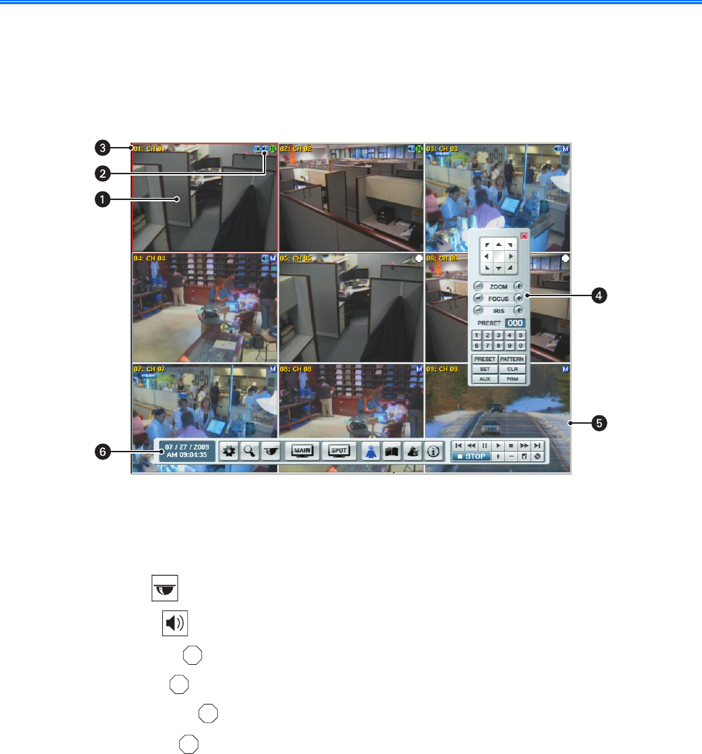
Figure 1. Application Window
ìView Panels: Displays live and playback video from attached cameras. The DVR supports up to 16 view panes.
î Status Icons: Displays the status of the camera’s current operating modes:
•PTZ icon : Indicates that the channel is configured for PTZ operation.
•Audio icon : Indicates that the channel is configured for audio operation.
•No record icon : Indicates that video is not being recorded.
•Normal icon : Indicates that the normal recording mode is active.
•Alarm record icon : Indicates that alarm event recording mode is active.
Motion record icon : Indicates that motion event recording mode is active.
ïChannel Label: Displays the input channel number (01–08 or 01–16) and the assigned channel name.
ñPTZ Control: Allows users with access rights to operate camera lens control features and to program PTZ presets, patterns,
auxiliary outputs, and tours.
óRed Border: Indicates the selected channel.
rToolbar: GUI toolbar through which the DVR is operated and configured.
C
N
A
M
C2674M-C (7/09) 13
GUI Toolbar
The DX4500/DX4600 GUI toolbar is used to access the setup menus, dialog boxes, and controls that allow you to operate and configure the DVR.
You can use the USB mouse to easily and quickly change settings and operate the system. You can also operate the DX4500/DX4600 from the
front panel and remote control to perform the same functions. A client software application running on a computer allows you to remotely
operate and perform administrative tasks on the DVR.
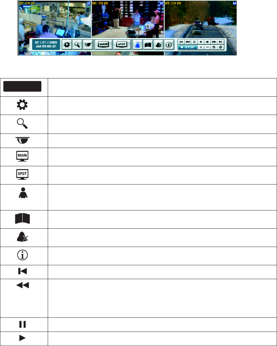
Figure 2. GUI Toolbar
Status: Shows the current date and time.
Setup: Opens the Setup window to access the following setup menus: camera, record, display, linking, network,
and system.
Search: Opens the Search window to select the following search criteria: media, date/time, event, bookmark, and
pixel search parameters.
PTZ: Opens the PTZ control to program the various PTZ features and control a PTZ camera.
MAIN: Opens the main monitor Select Starting Channel dialog box.
SPOT: Opens the spot monitor Select Starting Channel dialog box.
Login: Provides two functions:
•Login: Logs on the user. (The icon is black if no one is logged on to the DVR.)
•Logout: Logs off the user.
System Log: Displays the System Log List dialog box.
Alarm Off: Turns off the alarm.
Information: Displays the System Information dialog box.
Start: Starts playback for the selected date, beginning when data is first recorded.
Reverse: Provides two modes:
•Reverse playback: Plays back recorded video in the reverse direction at the normal speed. Repeatedly click
the icon to increase playback speed 2x, 3x, 4x, or 5x the normal speed.
•Step backward: Activates when playback is paused. Repeatedly click the icon to reverse playback,
frame-by-frame.
Pause: Pauses playback.
Play: Starts playing back video data.
06 / 07 / 2007
AM 10:18:56
14 C2674M-C (7/09)
Setup Menu
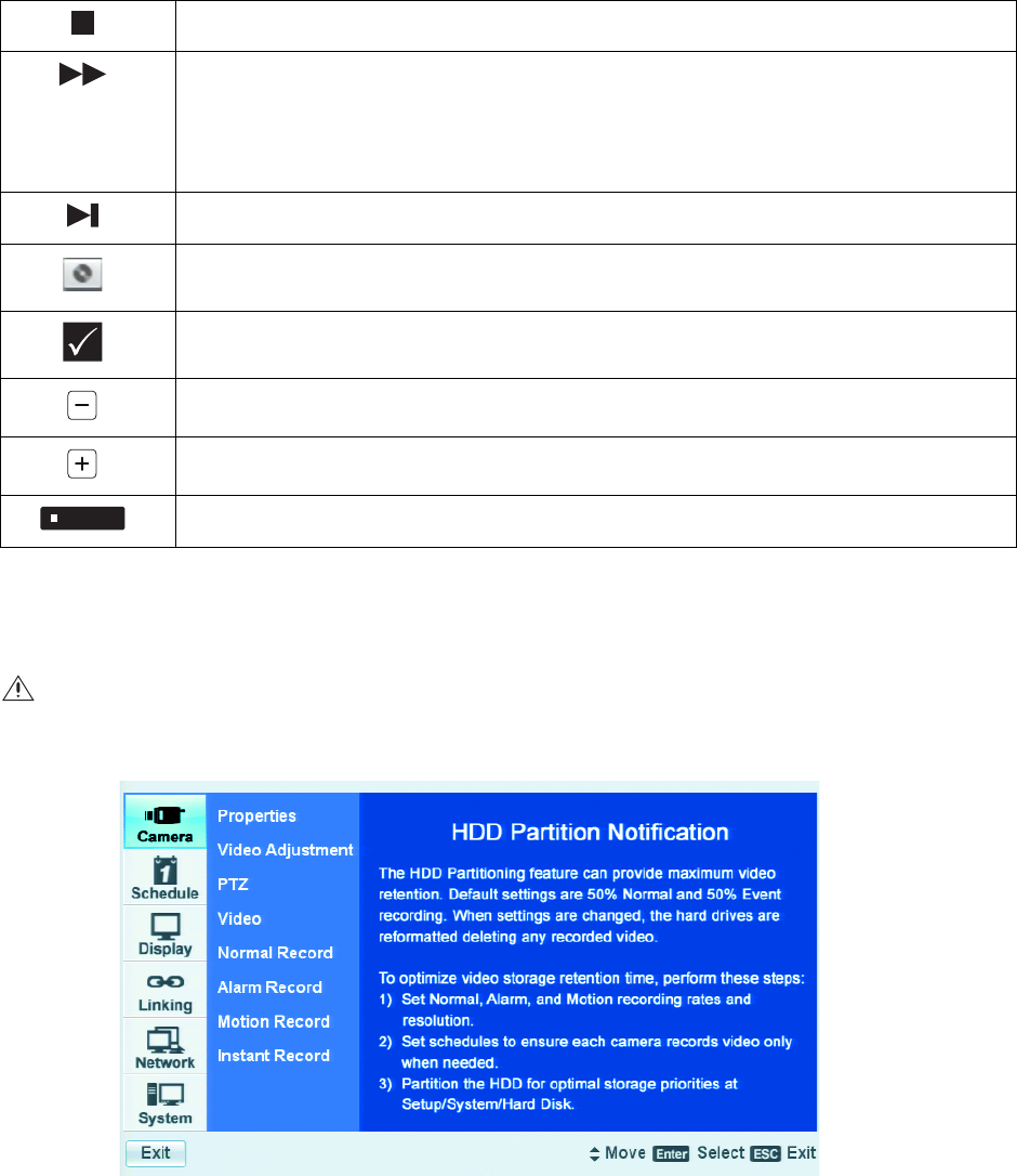
For information about using the Setup menu to configure the DX4500/DX4600, refer to Navigating the Setup Window on page 25.
Figure 3. Camera Menu HDD Partition Notification
Stop: Stops playback.
Forward: Provides two modes:
•Forward playback: Plays back recorded video in the forward direction at the normal speed. Repeatedly click
the icon to increase playback speed 2x, 3x, or 4x the normal speed.
•Step forward: Activates when playback is paused. Repeatedly click the icon to forward playback,
frame-by-frame.
End: Jumps to the last two minutes of the latest recorded data.
Copy/Export: Displays the Copy/Export dialog box.
Mark: Inserts a bookmark at the specified time during played back video.
Reduce: Reduces the size of the playback window.
Increase: Increases the size of the playback window.
Stop: Stops playback.
WARNING: Before you use the DX4500/DX4600 to record video, refer to Figure 3 and read the HDD Partition Notification.
STOP
C2674M-C (7/09) 15
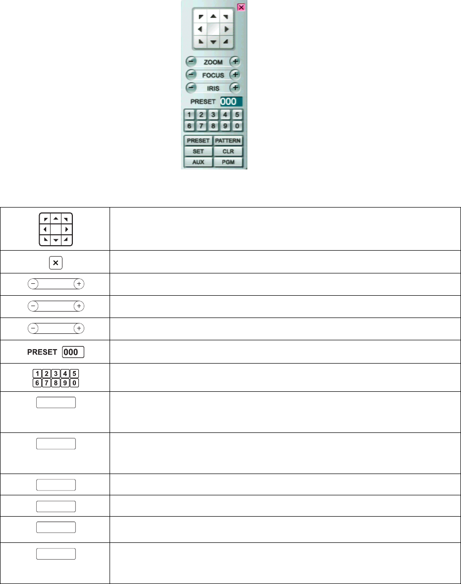
PTZ Control
The PTZ control is available for cameras that support PTZ functions using Pelco C, Pelco P, and D protocols. It is also available for supported third-
party dome cameras. In addition, the PTZ option must be enabled and a protocol must be assigned to the camera channel. For information about
configuring camera features, refer to Camera Menu Setup on page 27. For information using the KBD300A keyboard to operate PTZ devices, refer
to Activating Presets on page 100.
NOTE: When operating third-party cameras, the PTZ control supports the up, down, left, right, zoom in, and zoom out functions.
Figure 4. PTZ Control
Move: Pan and tilts the camera in the direction of the selected arrow.
Exit: Closes the PTZ control.
ZOOM: Zooms the camera in and out.
FOCUS: Adjusts the camera focus.
IRIS: Opens and closes the camera iris.
PRESET NUMBER: Displays the preset number.
Keypad: Enters presets or pattern numbers.
PRESET: Performs two functions:
•Preset programming mode: Stores the preset in the selected memory location.
•PTZ mode: Activates a preset.
PATTERN: Performs two functions:
•Pattern programming mode: Stores the pattern in the selected memory location.
•PTZ mode: Activates a pattern.
Clear: Deletes a programmed preset, pattern, or tour.
Program: Accesses the camera programming mode.
Auxiliary: Selects the auxiliary mode. Buttons 1–4 select the camera’s auxiliary outputs. Buttons 1–4
operate as a toggle (on/off) each time they are selected.
SET: Performs two functions:
• Enters PTZ programming mode.
• Exits PTZ programming mode.
ZOOM
FOCUS
IRIS
PRESET
PATTERN
CLR
PGM
AUX
SET
16 C2674M-C (7/09)
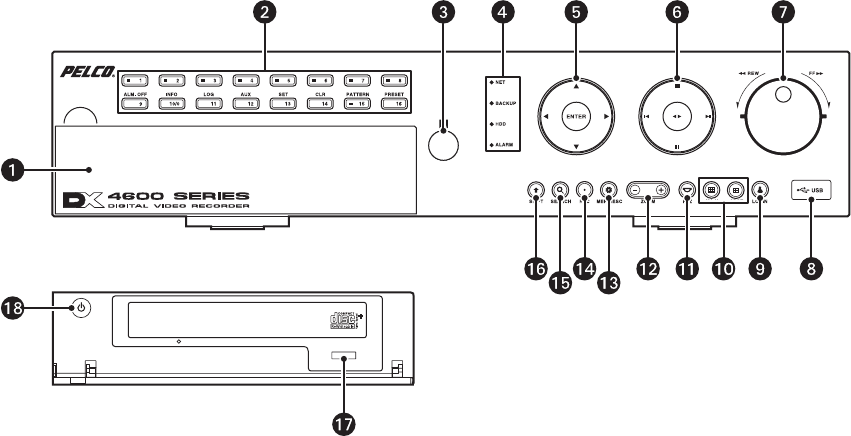
Front Panel
Figure 5. Front Panel
ìAccess Door: Provides access to the power switch and optical CD/DVD drive.
îChannel and Camera Control Buttons:
•Button [1]: Only selects camera 1.
•Buttons [2–8], Eight-Channel Unit or [2–16], Sixteen-Channel Unit: Selects the respective camera and its alternate
function. (Press the Shift button to access the alternate function).
[2] OSD: Toggles on and off the display of the toolbar.
[3] COPY: Copies recorded video data to the target media.
[4] MARK: Sets the beginning point from which to search recorded data.
[5] FOCUS-: Selects camera 5 or decreases camera focus.
[6] FOCUS+: Increases camera focus.
[7] IRIS-: Close camera iris.
[8] IRIS+: Opens camera iris.
[9] ALM OFF: Selects camera 9 or turns off active alarm state.
[10] INFO: Toggles on and off the display of system information.
[11] LOG: Toggles on and off the display of the log list.
[12] AUX: Sends an auxiliary command.
[13] SET: Starts the PTZ programming mode.
[14] CLR: Clears a programmed event.
[15] PATTERN: Assigns the recorded PTZ actions to the user-specified pattern number.
[16] PRESET: Assigns the position of the selected camera to a user-specified preset number.
ïRemote Sensor: Communicates between the DVR and remote control.
ñSystem Status Indicators:
•NET: Is lit when the network is connected.
•BACKUP: Is lit when the backup process is active.
•HDD: Blinks when the hard drive is accessed.
•ALARM: Is lit when the alarm out is in progress.
óSelection Control:
•Directional Arrows: (Up, down, left, and right) Navigate between the options of the Menu, Options, and Properties panes.
•Enter: Selects the highlighted option in the Menu, Option, and Properties panes.

C2674M-C (7/09) 17
rPlayback Controls:
Left Arrow: Provides two functions.
•Reverse: Searches recorded video at normal speed. Repeatedly press the button to search recorded video in the reverse
direction at 2x, 3x, or 4x the normal speed.
•Reverse Skip: Activates when playback is paused. Press the button to play back video frame-by-frame, or press the button
repeatedly to quickly skip through video in the reverse direction. Press and hold the button to go directly to the beginning of the
recorded video.
Right Arrow: Provides two functions.
•Forward: Searches recorded video at normal speed. Repeatedly press the button to search recorded video in the forward
direction at 2x, 3x, or 4x the normal speed.
•Forward Skip: Activates when playback is paused. Press the button to search video frame-by-frame, or press the button
repeatedly to quickly skip through video in the forward direction. Press and hold the button to go directly to the end of the
recorded video.
STOP: Stops playback.
PAUSE: Pauses playback.
Play: Provides an alternate playback function for viewing video. Press to start playback in forward direction; press again to play
back video in the reverse direction.
sJog Control (inner dial): Navigates through various mode options.
•Menu Mode: Increases (clockwise) or decreases (counter-clockwise) the selected option values.
•Date/Time Search Mode: Increases (clockwise) or decreases (counter-clockwise) to select the start time from which to begin
playback. Played back video is displayed in the picture-in-picture view. The picture-in-picture view is displayed in one or four
panes.
•Event Search Mode: During the initial video playback mode, the inner jog dial does not change the playback parameters.
Once the shuttle dial is used to pause played back video, the inner jog allows you to search forward (clockwise) or backward
(counter-clockwise) through each frame.
•Bookmark Search Mode: Once the shuttle dial is used to pause played back video, the jog dial allows you to search forward
(clockwise) or backward (counter-clockwise) through each frame.
•Pixel Search Mode: In the pixel search setup view, the jog dial navigates through the options. Once an option is selected,
the jog dial increases (clockwise) or decreases (counter-clockwise) the option’s value.
Shuttle Dial (outer ring):
•Quick Lift and Release Action (clockwise or counter-clockwise): For any of the above search modes, the initial quick
lift and release of the shuttle causes the played back video to pause. Subsequent quick lift and release actions searches the
played back video in the forward (clockwise) or reverse (counter-clockwise) direction, one frame at a time.
•Turn and Hold Action (clockwise or counter-clockwise): Turn the shuttle a little further to search the played back video
in the forward (clockwise) or reverse (counter-clockwise) direction faster, frame-by-frame. Turning the shuttle a full rotation in
either direction searches the playback at the fastest rate. The playback returns to pause when the shuttle is released.
tHigh-Speed USB 2.0 Ports: One port on the front and two on the back of the DVR.
uLOGIN: Displays the login dialog box if a user is not logged on to the system. If a user is already logged on, pressing this button logs
off the user. When a user is logged on, the button is lit blue; when a user is not logged on, the button is not lit. This button performs
the same function as the Login icon on the toolbar.

18 C2674M-C (7/09)
~í Monitor Selection:
• Main: Displays the Selecting Starting Channel dialog box, to select the window presentation as viewed on the VGA or main
analog monitor. Use in conjunction with buttons 1–8 or 1–16, to select which camera input is displayed first on the VGA or
main analog monitor. This button performs the same function as the MAIN icon on the GUI toolbar.
•VGA monitor selection: If the main video is displayed on the analog monitor, use the MAIN button to switch the display of
to the VGA monitor. Press the MAIN button for approximately 5 seconds until the system sounds a beep and restarts.
•SPOT: Displays the Selecting Starting Channel dialog box, to select the window presentation as viewed on a spot monitor.
Use in conjunction with buttons 1–8 or 1–16 to configure the first camera displayed. This button performs the same function
as the SPOT icon on the GUI toolbar.
•Analog Main BNC output: If the main video is displayed on the VGA monitor, use the SPOT button to switch the display to
the analog monitor connected to MAIN-OUT BNC.
~â PTZ: Displays the PTZ dialog box for a camera configured for PTZ control. This button performs the same function as the PTZ icon
on the GUI toolbar.
~ä ZOOM: Zooms a camera in and out.
~ã MENU/ESC:
• Displays the setup menu.
• Closes the setup menu.
~å REC: Manually starts and stops recording.
~ç SEARCH: Displays the Search window and is organized into the following categories:
•INTERNAL HDD: Selects the target media to search for data.
•Data/Time Search: Displays the date/time monthly calendar view. The search criteria is based on the date, time, and
camera/channel.
•Event Search: Displays the event type view and selections (ALARM, ALL, and MOTION). The event search criteria includes
date, time, camera/channel, and event type.
•Bookmark Search: Displays the bookmark search view to locate previously recorded bookmarks (data and channel/camera
number).
~é SHIFT: Switches the operation of the camera control buttons from the primary to secondary function.
~è DVD drive: Accepts DVD disks.
~ê Power switch: Turns on and off power to the unit.
C2674M-C (7/09) 19
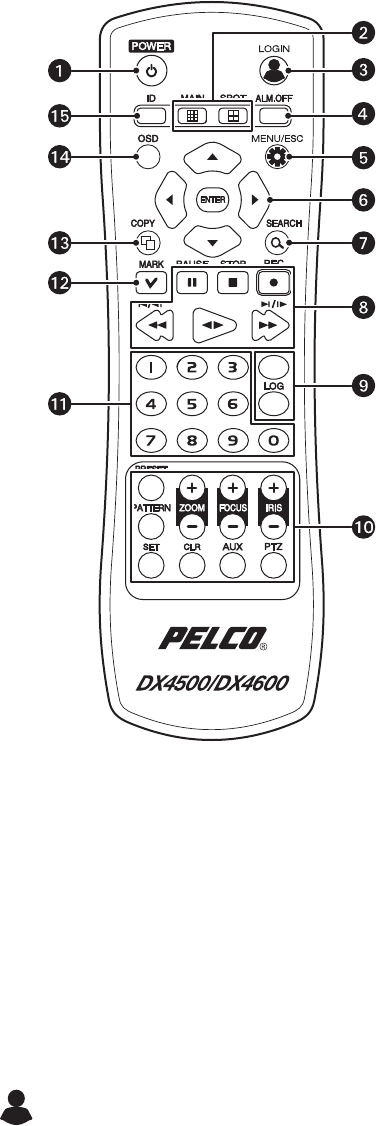
Remote Control
Figure 6. Remote Control
.
ìPOWER:
• Turns on the unit.
• If the DVR is turned on but a user is not logged on, the message “You have to login first” appears.
• If a user is already logged on, the message “Please enter the password” appears. If there is no activity for a period of time,
the dialog box disappears.
îChannel Selection:
•MAIN: Displays the Selecting Starting Channel dialog box, to select the window presentation as viewed on the VGA or
main analog monitor. Use in conjunction with buttons 1–8 or 1–16 to configure the first camera input displayed on the VGA
or main analog (MAIN-OUT BNC) monitor. This button performs the same function as the MAIN icon on the GUI toolbar.
•SPOT: Displays the Selecting Starting Channel dialog box, to select the window presentation as viewed on a spot monitor.
Use in conjunction with buttons 1–8 or 1–16 to configure the first camera input is displayed. This button performs the same
function as Login icon on the GUI toolbar.
ïLOGIN: Displays the login dialog box if a user is not logged on to the system. If a user is logged on, pressing this button logs the
user out. When a user is logged on, the button is lit blue; if a user is not logged on, the button is not lit. This button performs the
same function as the person icon on the GUI toolbar.
ñALM.OFF: Turns off an active alarm for the selected camera. Also cancels alarm activation and returns the system to the
condition before the alarm was activated.
óMENU/ESC: Toggles on and off the display of the setup menu.
20 C2674M-C (7/09)
rSelection Controls:
•Arrow Buttons: Selects menu options.
•ENTER: Selects the highlighted menu item.
sSEARCH: Displays the Search menu.
tPlayback Controls:
•PAUSE: Pauses playback.
•STOP: Stops playback.
•REC: Starts and stops recording.
•REVERSE: Searches recorded video in the reverse direction.
•FORWARD: Searches recorded video in the forward direction.
uSystem Buttons:
•System Information: Displays the System Information dialog box.
•System Log: Displays the System Log dialog box.
~í PTZ Controls:
•ZOOM +/-: Zooms in and out on the video image displayed in live and playback mode.
•FOCUS +/-: Adjusts the camera’s focus.
•IRIS +/-: Adjusts the camera’s iris.
•PTZ: Starts the PTZ mode for the selected device and displays the on-screen control.
•AUX: Sends an auxiliary command to the specified PTZ camera.
•CLR: Clears a programmed event.
•SET: Starts the PTZ programming mode.
•PATTERN: Assigns the recorded PTZ actions to the user-specified pattern number.
•PRESET: Assigns the position of the selected camera to a user-specified preset number.
~â Numbers 0 to 9: Used to assign the system ID, PTZ preset and pattern numbers, auxiliary command, and select the camera
channel in the search mode.
~ä MARK: Sets the starting location from which to conduct a search.
~ã COPY: Copies the specified recorded data to an external device.
~å OSD: Toggles on and off the display of the system toolbar.
~ç ID: Sets the appropriate DVR system ID through which to operate. Press the ID button, and then press the number button (within
two seconds) to select the system ID of the DVR. If you set the system ID to 0 (zero), you can control multiple DVRs at the
same time.
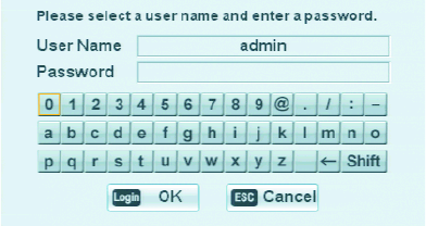
C2674M-C (7/09) 21
Virtual Keyboard
The DX4500/DX4600 provides a virtual on-screen keyboard to perform the following:
• Select a user name and type the a password to log on or off of the DVR.
• Create camera names.
• Create holiday schedule names.
• Assign TCP/IP settings (IP address, subnet mask, and so forth).
• Set up mail accounts.
• Assign emergency agent IP addresses.
• Create user accounts.
Figure 7 describes the Login Virtual Keyboard and its functions. All DX4500/DX4600 virtual keyboards operate similarly, but display different
fields depending on the task being performed.
Figure 7. Virtual Keyboard
ìData Field 1: The field for entering user data; in this example, the user name.
îData Field 2: The field for entering user data; in this example, the password.
ïVirtual Keyboard: The keys for entering the data in fields 1 and 2.
Space: (The blank key to the right of the Z) Inserts one space to the right of the previous character.
Backspace: (The back arrow) Deletes one character, beginning at the end of the text string.
Shift: Changes the case of the text and alternates between numbers and special characters.
•Uppercase: A to Z, numbers 0 to 9, and special characters.
•Lowercase: a to z, numbers 0 to 9, and special characters.
ñOK/Cancel: Accepts or cancels the performed action in fields 1 and 2.
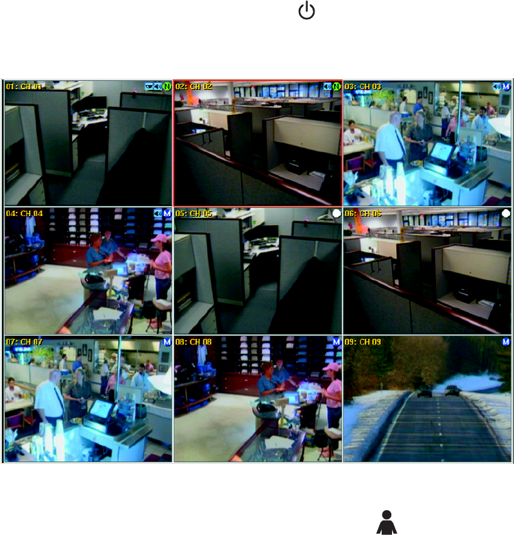
22 C2674M-C (7/09)
Turning On and Logging On to the DVR
You must log on to the DX4500/DX4600 with a valid user name (ID) and password to operate the DVR. User names and passwords are case
sensitive. By default, the DX4500/DX4600 comes with one login account; the user name is admin and the default password is admin.
NOTE: If you are logging on for the first time, the system does not prompt you to change the default (ADMINISTRATOR) password. If you keep
the default password, access to the DVR is easily accomplished by anyone who knows the user name (ID) and default password. Therefore, Pelco
strongly recommends that the system administrator change the password and keep it in a secured location. (The user name or access level,
which by default is Administrator, cannot be changed.)
1. On the front panel or remote control, press and hold the power button until your hear a beep, and then release the button. After a few
seconds, the DX4500/DX4600 startup screen is displayed.
2. Wait until the DVR displays the application window.
Figure 8. Application Window and GUI Toolbar
3. On the front panel or remote control, press Login. Using the mouse, click the Login icon . The Login dialog box opens. Use the virtual
keyboard to enter the password.
The password has the following guidelines:
• Characters: A to Z, a to z, numerals 0 to 9, and special characters.
• Name Length: From 4 to 8 characters long.
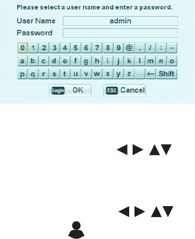
C2674M-C (7/09) 23
By default, the letters on the virtual keyboard are lowercase (a to z). It also uses numerals 0 to 9, and special characters.
Figure 9. Login Virtual Keyboard
4. To enter the default password, do one of the following:
• On the front panel or remote control, press the arrow buttons to select “a” from the virtual keyboard, and then press
ENTER. Repeat this process to select the remaining characters.
• Using the mouse, click each character of the password.
An asterisk appears in the Password entry box.
5. On the front panel or remote control, press any of the arrow buttons to select OK, and then press ENTER. Using the mouse,
click OK. The system logs you on and the Login icon changes color, indicating that you have successfully logged on to the DVR.
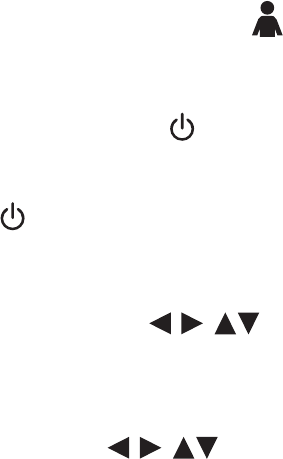
24 C2674M-C (7/09)
Logging Off and Turning Off the DVR
On the front panel or remote control, press LOGIN. Using the mouse, click the Login icon . The Login icon changes from blue to black,
indicating you are logged off.
You must be logged on to the DVR with administrator level permission to turn off the DX4500/DX4600.
1. On the front panel or remote control, press and hold the power switch until you hear a beep.
• If you are not logged on with administrator level permission, do the following:
(1) Log on at the administrator level.
(2) Press and hold the power switch until you hear a beep.
The Login virtual keyboard opens. You have approximately 25 seconds to enter the password before it closes.
2. To enter the password, do one of the following:
• On the front panel or remote control, press the arrow buttons to select the password character on the virtual
keyboard, and then press ENTER. Repeat this process until you have entered every character of the password.
• With the mouse click each password character on the virtual keyboard.
Asterisks representing each password character are displayed in the Password field.
3. On the front panel or remote control, press the arrow buttons to select OK, and then press ENTER. On the toolbar, click OK
with the mouse. The system turns off.
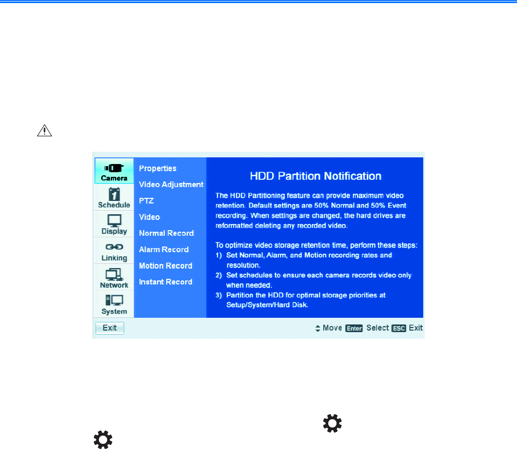
C2674M-C (7/09) 25
Set Up
Setup Window
The DX4500/DX4600 comes preconfigured with system defaults that allow you to immediately begin using the DVR to view live video. For a
description of all of the system defaults, refer to DX4500/DX4600 Factory Defaults on page 127.
The DX4500/DX4600 Setup window allows you to configure the DX4500/DX4600 operation for your particular security application. Only
administrator-level users have permission to access the Setup window and configure the DVR.
Figure 10. Camera Menu HDD Partition Notification
NAVIGATING THE SETUP WINDOW
1. Log on to the DVR at the administrator level. The DVR application window and toolbar are displayed.
2. On the front panel, press the MENU/ESC button or press the MENU/ESC button on the remote control. Using the mouse, click the
Setup icon . By default, the Setup window opens and the Camera menu is selected. Figure 11 describes how the Setup window is
organized and explains how to navigate the Menu, Option, and Properties panes to change settings.
WARNING: Before you use the DX4500/DX4600 to record video, refer to Figure 10 and read the HDD Partition Notification.
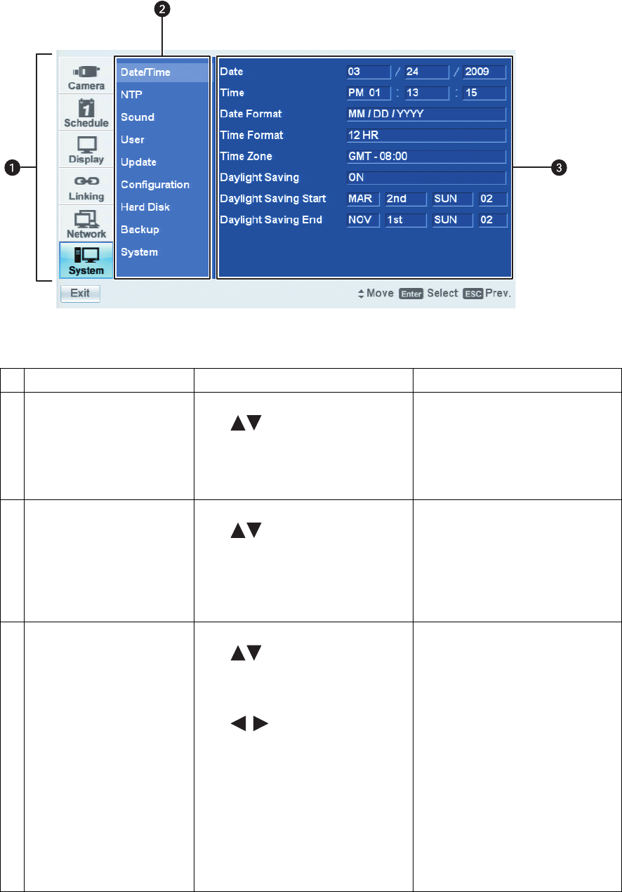
26 C2674M-C (7/09)
Figure 11. Setup Window Panes
Pane Front Panel/Remote Control Mouse
ìMenu: Displays the menu
commands.
• Press the up/down arrow buttons
to move to a menu command.
• Press ENTER to select a menu
command. When a menu command is
selected, the cursor moves to the Option
pane.
Click a menu command.
îOption: Displays the options for
the selected menu command.
• Press the up/down arrow buttons
to move to an option. Options
are displayed for each highlighted
option.
• Press ENTER to select an option. When
an option is selected, the cursor moves
to the Properties pane.
Left click a command, property, or option
to select it. Right- or left-click a selected
settings box to increase or decrease the
value.
ïProperties: Displays the
properties and settings available
for each option.
• Press the up/down arrow buttons
to move to a property. Properties
and related settings are displayed for
each highlighted option.
• Press the left/right arrow buttons
to navigate the Property
settings boxes. After an entry box is
selected, press ENTER to choose a
value. (Some property support settings
have multiple parts. For example, the
date property supports three settings: a
separate entry box for the month, day,
and year [MM/DD/YYYY]).
• Press ENTER to select a property or
settings box. The selected box changes
color.
Click a property or settings box. Right- or
left-click to choose a value.
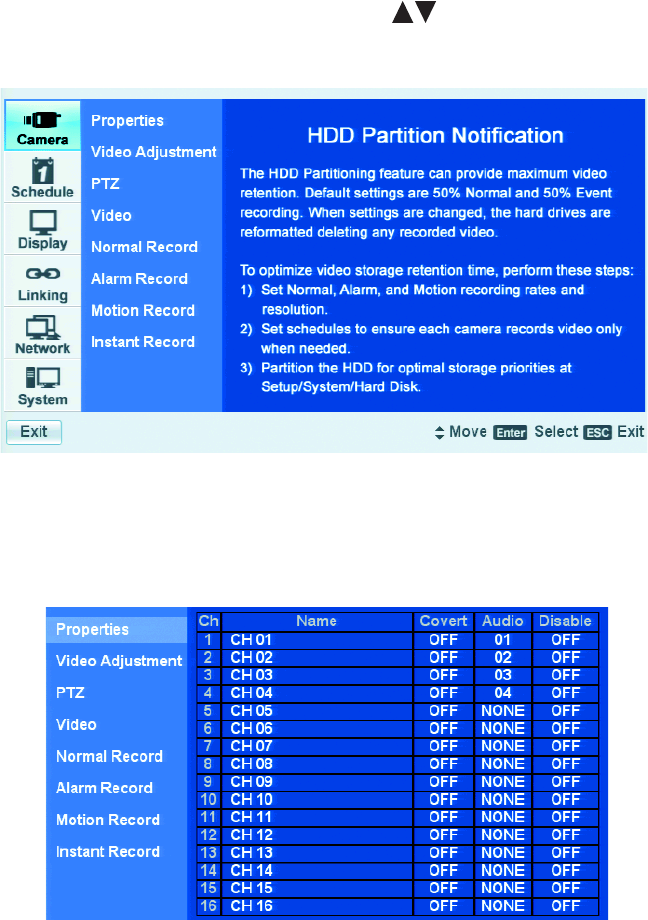
C2674M-C (7/09) 27
Camera Menu Setup
1. On the front panel or remote control, press the up/down arrow buttons to highlight the Camera menu. Using the mouse, click the
Camera menu. The camera options are displayed.
Figure 12. Camera Menu
2. On the front panel or remote control, press ENTER. Using the mouse, click the Properties menu. The Properties option is highlighted and the
property settings are displayed.
Figure 13. Properties Option Settings
•Name: Allows you to create a unique name for each camera. The camera name has the following guidelines:
–Characters: A to Z, a to z, numerals 0 to 9, and special characters.
–Name length: Up to 13 characters.
•Covert: Allows a camera to be configured, viewed, and operated by users who are logged on with administrator level permission. In the
covert mode, if a user is logged on with power or normal level permission, Video Loss is displayed in live view.
•Audio: Associates the audio input (1–4 [DX4516/DX4616] or 1–2 [DX4508/DX4608]) with a specified camera input.
•Disable: The camera can be enabled or disabled from displaying video.
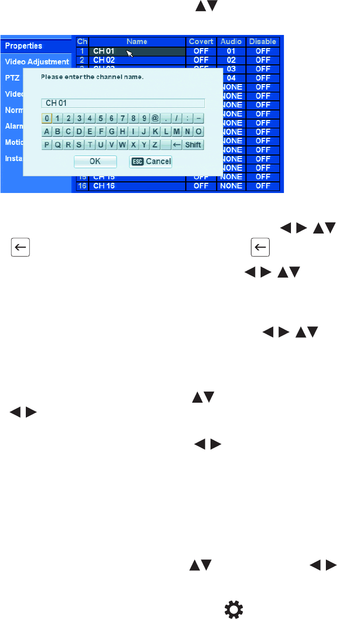
28 C2674M-C (7/09)
3. To create a camera name, do the following:
a. On the front panel or remote control, press ENTER. Using the mouse, click CH 01. The channel 01 name box is highlighted.
b. On the front panel or remote control, press the up/down arrow buttons to highlight a channel, and then press ENTER. Using
the mouse, click a channel name box. the “Please enter the channel name” virtual keyboard opens.
Figure 14. Channel Name Virtual Keyboard
c. To delete the existing name, on the front panel or remote control, press any of the arrow buttons to highlight the
backspace key , and then press ENTER. Using the mouse, click the backspace key until the name is deleted.
d. To type a name using the front panel or remote control, press any of the arrow buttons to highlight a character from
the virtual keyboard, and then press ENTER. Using the mouse, click a character. The selected character is displayed in the channel
name box.
e. Repeat step d until the camera name is typed in the channel name box.
f. To confirm the entry using the front panel or remote control, press any of the arrow buttons to highlight OK. Using
the mouse, click OK. The camera name is displayed in name box.
g. Repeat steps 2 and 3 to name other cameras.
4. To configure a camera for covert operation, perform steps 4a to 4d for each camera designated for covert operation.
a. On the front panel or remote control, press the up/down arrow buttons to highlight a channel number. Then press the left/right
arrow buttons to highlight the covert settings box and press ENTER. Using the mouse, click a settings box. The covert box
changes color.
b. On the front panel or remote control, press the left/right arrow buttons . Using the mouse, right- or left-click the settings box
to toggle the convert setting to ON.
c. On the front panel or remote control, press ENTER. Using the mouse click in another settings box. The covert box changes color.
d. Repeat steps 3a–3c to configure other cameras for covert operation.
e. When an administrator-level user is logged on to the unit, video from covert cameras displays on the spot monitor. If you do not want
video to display on the spot monitor, refer to Display Menu Setup on page 49 and perform the steps to configure the spot monitor for
covert operation.
5. To configure the audio and disable setting, do the following:
a. On the front panel or remote control, use the up/down arrow buttons , the left/right arrow buttons , and the ENTER
button to highlight and change the audio and disable setting for the respective channels.
6. To exit the properties settings and return to the Options pane, do the following:
a. On the front panel, press the MENU/ESC button or press the MENU/ESC button on the remote control. Using the mouse, click
Properties.
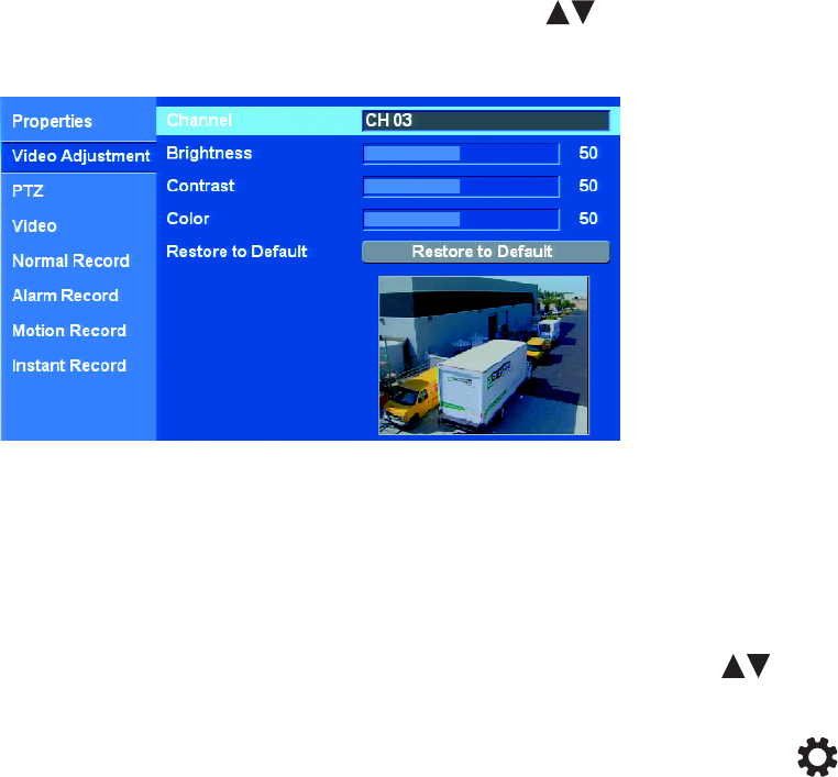
C2674M-C (7/09) 29
VIDEO ADJUSTMENT
The video adjustment option allows you to set the characteristics (brightness, contrast, and color) of displayed video, and how it is recorded and
stored for each camera.
1. From the options pane, on the front panel or remote control, press the up/down arrow buttons to highlight Video Adjustment. Using
the mouse, click Video Adjustment. The Video Adjustment option is highlighted and the property settings are displayed.
Figure 15. Video Adjustment Option Settings
2. On the front panel or remote control, press ENTER. Using the mouse, click Channel. The Channel 01 name box is highlighted.
3. Use the front panel, remote control, or mouse to select a channel. Adjust the brightness, contrast, and color of the display on the monitor.
Be sure to preview the video display in the preview window before finalizing your selection.
4. Repeat step 3 for each camera for which you want to adjust the video output display.
5. To reset the settings for the current channel using the front panel or remote control, press the up/down arrow buttons to highlight
“Restore to Default”, and then press ENTER. Using the mouse, click Restore to Default. The setting for the current channels are reset to the
factory defaults.
6. To accept the settings and exit Video Adjustment, press the MENU/ESC button on the front panel or press the MENU/ESC button on
the remote control. Using the mouse, click Video Adjustment. The Video Adjustment option is highlighted.
PTZ SETUP
PTZ devices are connected to the DX4500/DX4600 using the DATA 1 and DATA 2 RS-422/RS-485 ports located on the back of the unit. The
DX4508/DX4608 supports up to 8 serial PTZ cameras; the DX4516/DX4616 supports up to 16 serial PTZ cameras. Multiple PTZ cameras are
connected by daisy-chaining the camera connections. The DX4500/DX4600 allows you to address and control multiple PTZ cameras individually.
NOTE: You might experience operational issues when a camera device is not correctly terminated. When connecting camera devices, use a
normal load termination of 75 ohms. When looping through DVR inputs, ensure that the signal is terminated at the end device. For additional
information about terminating a specific camera device, refer to the device’s installation manual.
Before you perform the PTZ setup procedure, you will need the following information for each PTZ camera being configured:
• Channel to which the PTZ camera is attached
• Data port to which the camera is connected
• Pelco D and Pelco P address
• Camera protocol
• Communication settings: Baud rate, parity, data bits, and stop bits
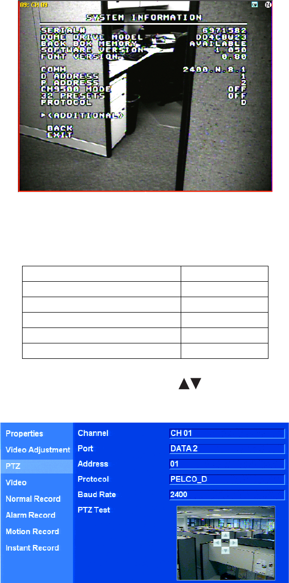
30 C2674M-C (7/09)
Figure 16. PTZ Camera Information
Table C lists the supported third-party devices and the protocol used by each device to operate the pan/tilt/zoom, focus, iris, and preset features.
1. On the front panel or remote control, press the up/down arrow buttons to highlight PTZ. Using the mouse, click PTZ. The PTZ option
is highlighted and the property settings are displayed.
Figure 17. PTZ Option Settings
Table C. Third-Party PTZ Compatibility
Third-Party PTZ Device Protocol
Bosch® AutoDome® Day/Night Bosch_AutoDome
Samsung™ SCC 641 Samsung_SCC
LG™ LPT-SD163HM LG_SD168
Baxall™ BPD1-RAS916 Pelco P
American Dynamics™ Speed Dome Ultra Vll Pelco P

C2674M-C (7/09) 31
2. To select a PTZ channel, do the following:
a. On the front panel or remote control, press ENTER. Using the mouse click Channel. The Channel property is highlighted.
b. On the front panel or remote control, press ENTER, or click in the settings box. The channel settings box changes color.
c. On the front panel or remote control, press the left/right arrow buttons . Using the mouse, right- or left-click the settings box
to display the channels.
d. When the channel you want to configure is displayed, do one of the following:
• On the front panel or remote control, press ENTER. The settings box changes color.
• Using the mouse, click Port. The channel settings box changes color and the Port property is highlighted.
3. To set the PTZ port for the current channel and camera, do the following:
a. On the front panel or remote control, press the left/right arrow buttons to highlight Port. If using the mouse and the Port
property is not highlighted, click Port. The Port option is highlighted.
b. On the front panel or remote control, press ENTER. Using the mouse, left-click the settings box. The port settings box changes color.
c. On the front panel or remote control, press the left/right arrow buttons . Using the mouse, right- or left-click the settings box
to display the port choices (NONE, DATA 1, DATA 2).
d. When the port you want is displayed, do one of the following:
• On the front panel or remote control, press ENTER. The settings box changes color.
• Using the mouse, click Address. The channel settings box changes color and the Address property is highlighted.
4. To set the camera address, do the following:
a. On the front panel or remote control, press the up/down arrow buttons to highlight Address. If using the mouse and the
Address property is not already highlighted, click Address.
b. On the front panel or remote control, press ENTER. Using the mouse, left-click the settings box. The settings box changes color.
c. On the front panel or remote control, press the left/right arrow buttons . Using the mouse, right- or left-click the settings box
to display the settings.
d. When the setting you want is displayed, do one of the following:
• On the front panel or remote control, press ENTER. The settings box changes color.
• Using the mouse, click Protocol. The address property settings box changes color and the Protocol property is highlighted.
5. To select the PTZ camera protocol, do the following:
a. On the front panel or remote control, press the up/down arrow buttons to highlight Protocol. Using the mouse and the Protocol
property is not already highlighted, click Protocol.
b. On the front panel or remote control, press ENTER. Using the mouse, left-click the settings box. The settings box changes color.
c. On the front panel or remote control, press the left/right arrow buttons . Using the mouse, right- or left-click the settings box
to display the settings.
d. When the protocol setting you want is displayed, do one of the following:
• On the front panel or remote control, press ENTER. The settings box changes color.
• Using the mouse, click Baud Rate. The protocol property settings box changes color and the Baud Rate property is highlighted.
6. To set the PTZ camera baud rate, do the following:
a. On the front panel or remote control, press the up/down arrow buttons to highlight Baud Rate. Using the mouse and the Baud
Rate property is not already highlighted, click Baud Rate.
b. On the front panel or remote control, press ENTER. Using the mouse, left-click the settings box. The settings box changes color.
c. On the front panel or remote control, press the left/right arrow buttons . Using the mouse, right- or left-click the settings box
to display the settings.
d. When the baud rate setting you want is displayed, do one of the following:
• On the front panel or remote control, press ENTER. The settings box changes color.
• Using the mouse, click PTZ Test. The baud rate property settings box changes color and the PTZ Test property is highlighted.
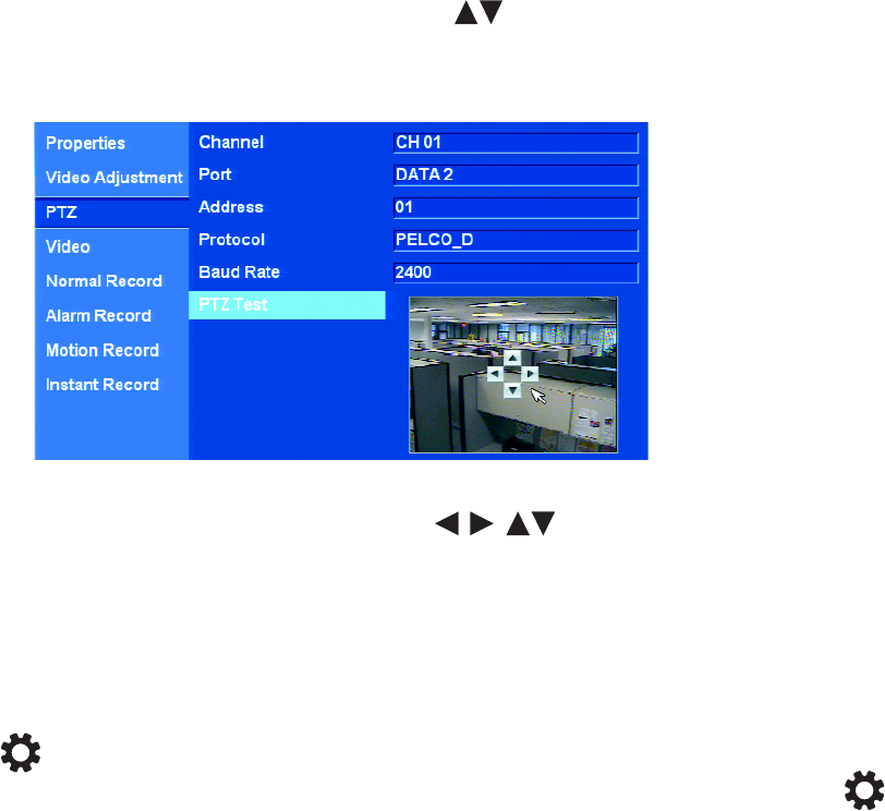
32 C2674M-C (7/09)
7. To conduct a PTZ test to verify communication with the camera, do the following:
a. On the front panel or remote control, press the up/down arrow buttons to highlight PTZ Test. If using the mouse and the PTZ
Test property is not already highlighted, click PTZ Test.
b. On the front panel or remote control, press ENTER. Using the mouse, left-click the window. The PTZ test controls are available. Refer
to Figure 18.
Figure 18. PTZ Test Controls
c. On the front panel or remote control, press any of the arrow buttons . Using the mouse, click any of the arrow
controls. The PTZ camera should respond.
d. When the baud rate setting you want is displayed, do one of the following:
• On the front panel or remote control, press ENTER. The settings box changes color.
• Using the mouse, click PTZ Test. The baud rate property settings box changes color and the PTZ Test property is highlighted.
8. To accept the settings and exit the PTZ Test mode, do one of the following:
•Remain in the PTZ setting pane/revisit a PTZ setting: On the front panel, press the MENU/ESC button or press the MENU/ESC
button on the remote control. The PTZ Test property is highlighted. If using the mouse, click the desired PTZ setting.
•Return to the Camera options pane: On the front panel, press the MENU/ESC button twice or press the MENU/ESC button
on the remote control twice. Using the mouse, click the desired option.
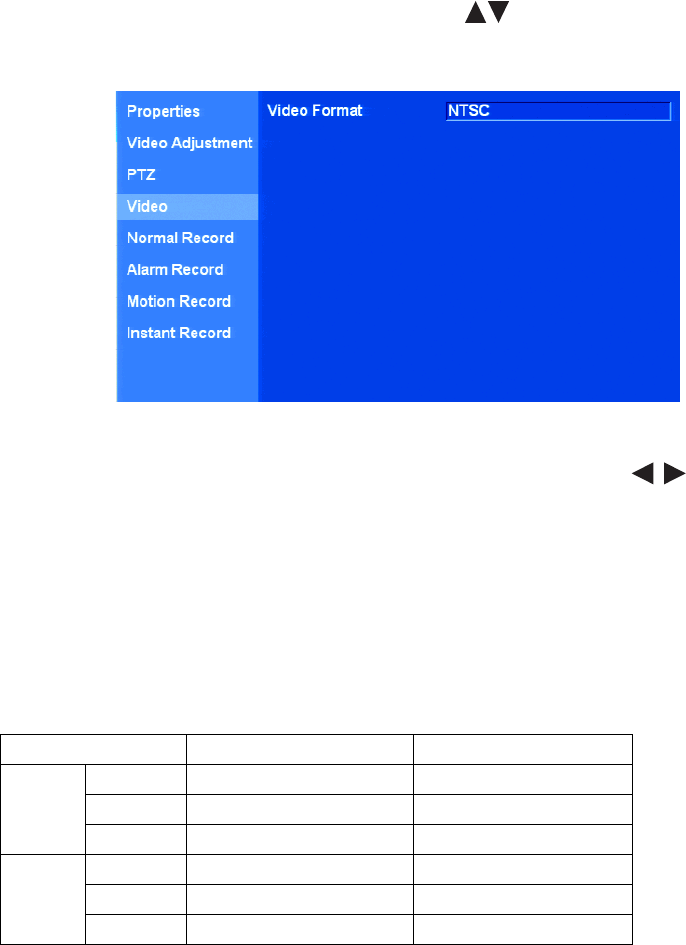
C2674M-C (7/09) 33
VIDEO SETUP
VIDEO FORMAT
1. On the front panel or remote control, press the up/down arrow buttons to highlight Video. Using the mouse, click Video. The Video
option is highlighted and the Video Format property setting is displayed.
Figure 19. Video Option Settings
2. On the front panel or remote control, press ENTER twice. Then press the up/down arrow buttons to select NTSC (default) or PAL
video format. Using the mouse, click the settings box to select NTSC or PAL.
3. On the front panel or remote control, press ENTER. Then press MENU/ESC. Using the mouse, click the Video option.
RECORDING SETUP
NOTE: The DX4500/DX4600 has unique MPEG-4 recording characteristics. Images recorded at frame rates less than 7 ips, when viewed using
the DX4500/DX4600 Client Application software, might not be evenly distributed over a one-second interval.
The DX4500/DX4600 allows you to configure the following record settings for each camera:
•Quality of recording picture: Lowest, low, standard, high, and highest.
•Pre-alarm recording time: OFF, 5, 10, 20, 30, 40, 50, and 60 seconds. Specifies the amount of time the DVR stores video recorded prior
to the beginning of an alarm or motion event.
•Post-alarm recording time: OFF, 10, 20, 30, 40, or 50 seconds or 1, 2, 3, 5, or 10 minutes. Specifies the amount of time that the DVR
continues to record video after the alarm or motion event ends.
Resolution DX4608/DX4616 Settings DX4508/DX4516 Settings
NTSC 352 x 240 1, 3, 5, 7.5, 15, 20, 30 1, 3, 5, 7.5, 15
704 x 240 1, 3, 5, 7.5, 15 1, 3, 5, 7.5
704 x 480 1, 3, 5, 7.5 1, 3
PAL 352 x 288 1, 3, 5, 6, 12.5, 20, 25 1, 3, 5, 6, 12.5
704 x 288 1, 3, 5, 6, 12.5 1, 3, 5
704 x 576 1, 3, 5, 6 1, 3
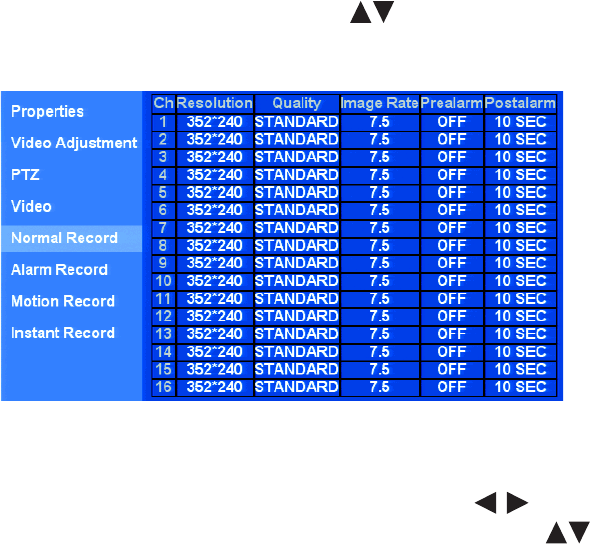
34 C2674M-C (7/09)
1. On the front panel or remote control, press the up/down arrow buttons to highlight Record. Using the mouse, click Record. The
Record option is highlighted and the property settings are displayed.
Figure 20. Record Option Settings
2. To configure a record setting, do the following:
a. On the front panel or remote control, press ENTER. Press the left/right arrow buttons to select the resolution, quality, image
rate, pre-alarm, and post-alarm fields, and press ENTER. Then press the up/down arrow buttons to set the settings for a
channel. Using the mouse, click the settings.
b. Repeat step 2a for additional channels.
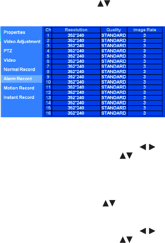
C2674M-C (7/09) 35
MULTI-EVENT RECORDING SETUP
NOTE: Only the DX4600 supports multi-event recording.
Multi-event recording includes any single event or combination of events associated with an instant, alarm, or motion recording. Instant record is
the highest priority recording event. The DX4600 allows you to schedule each camera to record in a single- or multiple-event mode across a
24-hour timeline. Users with administrator access can schedule video recording for one or more cameras. You can also configure each camera to
record at a specific resolution, quality, and image rate when an event is triggered.
•Setting up multi-event camera recording properties: Refer to the instant, alarm, and motion record instructions in this section.
•Setting up recording schedules: Use the Setup window Schedule menu to configure the recording schedule for each camera. For
information about the Schedule menu, refer to Schedule Menu Setup on page 37.
ALARM RECORD SETUP
1. On the front panel or remote control, press the up/down arrow buttons to highlight Alarm Record. Using the mouse, click Alarm Record.
The Alarm Record option is highlighted and the property settings appear.
Figure 21. Alarm Record Option Settings
2. To configure a channel’s record setting for an alarm event, do the following:
a. On the front panel or remote control, press ENTER. Press the left/right arrow buttons to select the resolution, quality, and
image rate fields, and press ENTER. Then press the up/down arrow buttons to set the settings for a channel. Using the mouse,
click the settings.
b. Repeat step 2a for additional channels.
MOTION RECORD SETUP
1. On the front panel or remote control, press the up/down arrow buttons to highlight Motion Record. Using the mouse, click Motion
Record. The Motion Record option is highlighted and the property settings appear.
2. To configure a channel’s record setting for a motion event, do the following:
a. On the front panel or remote control, press ENTER. Press the left/right arrow buttons to select the resolution, quality, and
image rate fields, and press ENTER. Then press the up/down arrow buttons to set the settings for a channel. Using the mouse,
click the settings.
b. Repeat step 2a for additional channels.

36 C2674M-C (7/09)
INSTANT RECORD SETUP
1. On the front panel or remote control, press the up/down arrow buttons to highlight Instant Record. Using the mouse, click Instant
Record. The Instant Record option is highlighted and the property settings appear.
2. To configure a channel’s record setting for a motion event, do the following:
a. On the front panel or remote control, press ENTER. Press the left/right arrow buttons to select the resolution, quality, and
image rate fields, and press ENTER. Then press the up/down arrow buttons to set the settings for a channel. Using the mouse,
click the settings.
b. Repeat step 2a for additional channels.
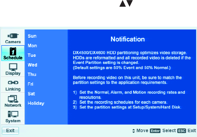
C2674M-C (7/09) 37
Schedule Menu Setup
The DX4500/DX4600 provides a flexible scheduling feature that allows you to create daily, weekly, and holiday schedules. Recording schedules
are easily created for each channel and changed without affecting the schedule of other channels. Up to 10 different holiday schedules can be
created. In this case, if a holiday schedule occurs on the same date as a weekday schedule, the holiday schedule will override the weekday
schedule. You can also initiate the manual record mode, which takes precedence over the current recording schedule. The DX4500/DX4600
supports copying schedules between channels, days, weekdays, and weekends.
The DX4500/DX4600 supports the five different color-coded scheduling modes:
•No record (white): The video is displayed, but does not record video.
•Normal (green): The DVR records video data continuously over a 24-hour period. This mode uses the most hard disk storage.
•Alarm (red): The DVR only records video if an alarm event is detected.
•Motion (blue): The DVR only records video if a motion event is detected.
•Multi-event recording: Only the DX4600 supports multi-event recording. For information about configuring DX4600 channels for
multi-event recording, refer to Multi-Event Recording Setup on page 35.
–Alarm or motion (yellow): The DVR only records video data if either an alarm or motion event is detected.
–Normal or Alarm (green and red): The DVR records normal video data until an alarm event is detected, and then switches to
recording alarm video data.
–Normal or motion (green and blue): The DVR records normal video data until a motion event is detected, and then switches to
recording motion video data.
–Normal, alarm, or motion (green and yellow): The DVR records normal video data until an alarm or motion event is detected, and
then switches to recording video for the detected event.
1. On the front panel or remote control, press the up/down arrow buttons to highlight the Schedule menu. Using the mouse, click the
Schedule menu. The schedule options are displayed.
Figure 22. Schedule Menu
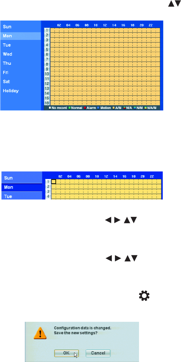
38 C2674M-C (7/09)
DAILY RECORDING SCHEDULE
1. To create a daily recording schedule, on the front panel or remote control, press the up/down arrow buttons to highlight a day of the
week. Using the mouse, click a day of the week. The option is highlighted and the schedule is displayed.
Figure 23. Daily Recording Schedule
2. To schedule channel 2 for normal recording between 0800 (8 a.m.) and 1600 (4:00 p.m.) and leave the default Alarm+Motion effective from
1600 to 2400, do the following:
a. On the front panel or remote control, press ENTER. Using the mouse, click a cell in the schedule grid. The first cell of channel 1 is
highlighted.
NOTE: The first cell of channel 1 is the default starting location for all channels.
Figure 24. Default Starting Location, Channel 1
b. On the front panel or remote control, press any of the arrow buttons to highlight cell 08 of channel 2, and then press
ENTER. Using the mouse click, cell 08 of channel 2. The starting time for channel 2 is marked at 08.
NOTE: Each time you select a cell in the schedule, the scheduling tool cycles through the recording modes beginning with “No record.”
c. Press ENTER or click the cell again. The marked cell for channel 2 at 08 turns green, as do the remaining cells in the row.
d. On the front panel or remote control, press any of the arrow buttons to move the cursor to cell 1600, and then press
ENTER. Using the mouse, click the cell until it turns yellow. The ending time for channel 2 is marked at 1600.
3. To save the normal recording schedule for channel 2, you must exit the Record mode and return to Live View.
a. To save the settings, do one of the following:
• On the front panel, press the MENU/ESC button or press the MENU/ESC button on the remote control until the
“Configuration data is changed. Save the new settings?” dialog box is displayed.
• Using the mouse, click Exit. The “Configuration data is changed. Save the new settings?” dialog box is displayed.
Figure 25. Saving the Recording Schedule
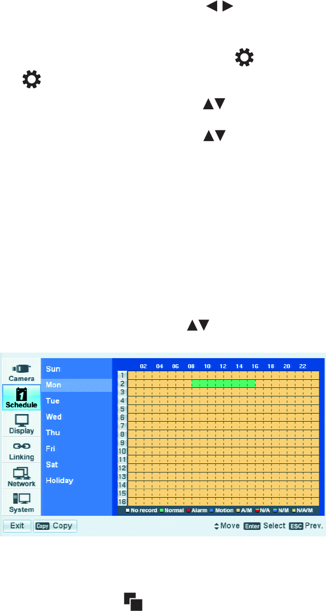
C2674M-C (7/09) 39
b. On the front panel or remote control, press the left/right arrow buttons to highlight OK, and then press ENTER. Using the
mouse, click OK. The settings are saved and the Live view mode is displayed.
4. To return to the Record mode, do the following:
a. On the front panel, press the MENU/ESC button or press the MENU/ESC button on the remote control. Using the mouse, click
the Setup icon . By default, the Setup window opens and the Camera menu is selected.
b. On the front panel or remote control, press the up/down arrow buttons to highlight Record. Using the mouse, click Record. The
Record option is highlighted and the property settings are displayed.
c. On the front panel or remote control, press the up/down arrow buttons to highlight another day of the week. Using the mouse,
click a day of the week. The option is highlighted and the schedule is displayed.
COPYING SCHEDULES
The DX4500/DX4600 supports four methods for copying schedules:
•Weekday (M–F): The schedule from the highlighted day is copied to the respective channels for every day of the week except Saturday
and Sunday.
•Weekend (Saturday and Sunday): The schedule from the highlighted day is only copied to the respective channels for Saturday and
Sunday. The schedule is not copied to the weekdays (Monday–Friday).
•Day (Sun–Sat): The schedule from the highlighted day is copied to the respective channels of the selected day.
•Channel-to-channel(s): The schedule from the selected channel is copied to the selected destination channel(s).
COPYING BY DAY, WEEKDAY, OR WEEKEND
1. On the front panel or remote control, press the up/down arrow buttons to highlight a day of the week. Using the mouse, click a day
of the week. The option is highlighted and the schedule is displayed.
Figure 26. Highlighting a Day’s Schedule
2. Do one of the following:
• On the front panel, press the SHIFT button, and then press the COPY button.
• On the remote control, press the COPY button or click copy.
• Using the mouse, click the Copy button.
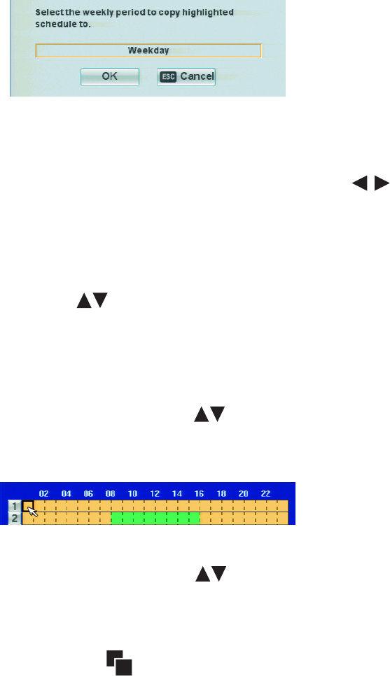
40 C2674M-C (7/09)
The “Select weekly period to copy highlighted schedule to” dialog box is displayed.
Figure 27. Weekly Period Dialog Box
3. To select the period to copy the schedule to, do the following:
a. On the front panel or remote control, press ENTER. Using the mouse, click the settings box. The settings box changes color.
b. To display the desired period, on the front panel or remote control, press the left/right arrow buttons . Using the mouse, click
the settings box to cycle through the available periods: Weekday, Weekend, Sunday, Monday, Tuesday, Wednesday, Thursday, Friday,
and Saturday.
4. When the desired period is displayed, do one of the following:
• On the front panel or remote control:
(1) Press ENTER. The setting is selected and the settings box changes color.
(2) Press the up/down arrow buttons to highlight OK, and then press ENTER.
• Using the mouse, click OK.
The schedule is copied to the destination period.
COPYING BETWEEN CHANNELS
1. On the front panel or remote control, press the up/down arrow buttons to highlight a day of the week. Using the mouse, click a day
of the week. The day option is highlighted and the schedule is displayed.
2. On the front panel or remote control, press ENTER. Using the mouse, click a cell in the schedule grid. The first cell of channel 1 is highlighted.
Figure 28. Initiating the Channel Copy Process
3. On the front panel or remote control, press the up/down arrow buttons to highlight a cell of the source channel. Using the mouse,
click a cell of the source channel.
4. Do one of the following:
• On the front panel, press the SHIFT button and then press the COPY button.
• On the remote control, press the COPY button .
• Using the mouse, click the copy button.
The “Select each destination channel that is to receive a copy of the recording schedule” dialog box is displayed. The source channel is
highlighted.
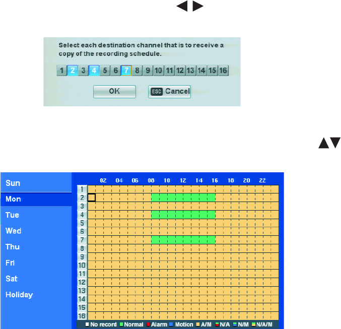
C2674M-C (7/09) 41
5. On the front panel or remote control, press the left/right arrow buttons to highlight each destination channel, and then press
ENTER. Using the mouse, click the channel(s). The channel button changes color.
Figure 29. Selecting Destination Channels
6. Once the destination channels are selected, on the front panel or remote control, press the up/down arrow buttons to highlight OK,
and then press ENTER. Using the mouse, click OK. The source channel’s schedule is copied to the destination channels.
Figure 30. Copying from a Source Channel
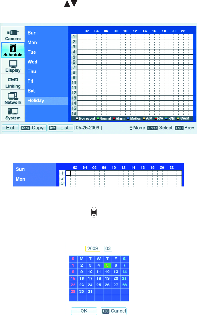
42 C2674M-C (7/09)
HOLIDAY SCHEDULES
The DX4500/DX4600 allows you to create up to 10 holiday schedules. If a holiday schedule occurs on the same date as a weekday schedule, the
holiday schedule will override the weekday schedule.
CREATING A HOLIDAY SCHEDULE
There are two ways to create a holiday schedule:
• Assign a date and name to the blank schedule
• Edit the blank schedule to configure the channel recording schedule
1. On the front panel or remote control, press to highlight Holiday, or with the mouse, click Holiday. The Holiday option is highlighted
and the schedule grid is displayed. By default, the Holiday schedule is set to no record.
Figure 31. Selecting the Holiday Option
2. On the front panel or remote control, press ENTER. Using the mouse click a cell in the schedule grid. The first cell of channel 1 is highlighted.
Figure 32. Initiating the Holiday Schedule Process
3. To assign the schedule to a date, do the following:
a. On the front panel or remote control, press ZOOM+ . Using the mouse, click Add. The monthly calendar is displayed. The current
day of the month is selected.
By default (when the calendar opens), the cursor highlights the year settings box.
Figure 33. Assigning a Date

C2674M-C (7/09) 43
b. On the front panel or remote control, press the left/right arrow buttons to highlight the month settings box, and then press
ENTER. Using the mouse, click the month settings box. The month settings box changes color.
c. On the front panel or remote control, press the left/right arrow buttons to select the desired month, and then press ENTER.
Using the mouse, right- or left-click the month settings box to select the month.
d. Press any of the arrow buttons to highlight the desired day of the month, and then press ENTER. Using the mouse,
click the day of the month. The month settings box changes color and the cursor moves to the selected date and changes color.
Figure 34. Selecting the Day of the Month
e. On the front panel or remote control, press any of the arrow buttons to highlight OK, and then press ENTER. Using
the mouse, click OK.
The “Please enter the name of the holiday” virtual keyboard opens. The holiday schedule name has the following guidelines:
•Characters: A to Z, a to z, numerals 0 to 9, and special characters.
•Name length: Up to 13 characters.
4. To create a name for the holiday schedule, do the following:
a. On the front panel or remote control, press any of the arrow buttons , and then press ENTER. Using the mouse, click
the keys to create the schedule name.
b. On the front panel or remote control, press any of the arrow buttons to highlight OK, and then press ENTER. Using
the mouse, click OK. The keyboard closes, the Holiday option is highlighted, and a blank holiday schedule is displayed.
5. Save the settings.
a. Do one of the following:
• On the front panel, press the MENU/ESC button or press the MENU/ESC button [INSERT GRAPHIC] on the remote control until
the “Configuration data is changed. Save the new settings message?” dialog box is displayed.
• Using the mouse, click Exit. The “Configuration data is changed. Save the new settings?” dialog box is displayed.
b. On the front panel or remote control, press the left/right arrow buttons to highlight OK, and then press ENTER. Using the
mouse, click OK. The settings are saved and the live view mode is displayed.
To configure the channel recording assignments to the newly created blank schedule:
6. To return to the holiday menu, press the MENU/ESC button on the front panel or press the MENU/ESC button [INSERT GRAPHIC] on the
remote control. Using the mouse, click the Setup icon [INSERT GRAPHIC]. By default, the Setup window opens and the Camera menu is
selected.
7. On the front panel or remote control, press the up/down arrow buttons to highlight Schedule, and then press ENTER. The schedule
options are displayed.
8. On the front panel or remote control, press the up/down arrow buttons to highlight Holiday. Using the mouse, click Holiday.
The blank holiday schedule is displayed.
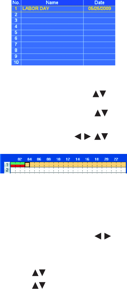
44 C2674M-C (7/09)
9. To open the blank schedule, do one of the following:
• On the front panel, press the SHIFT button, and then press the Info button.
• On the remote control, press the Info button.
• Using the mouse, click the Info button.
The Holiday List dialog box opens. The newly named schedule is displayed in the Holiday List table.
Figure 35. Holiday List Table
10. To edit the schedule to configure channel recording assignments, do the following:
a. On the front panel or remote control, press the up/down arrow buttons to highlight the schedule, and then press ENTER. Using
the mouse, click the schedule.
b. On the front panel or remote control, press the up/down arrow buttons to highlight Edit, and then press ENTER. Using the
mouse, click Edit. The selected schedule is displayed and the cursor is positioned in the first cell of channel 1.
11. On the front panel or remote control, use any of the arrow buttons to select the schedule grid, and then press ENTER.
Using the mouse, click the schedule grid to create a recording schedule for each channel required for the holiday schedule.
Figure 36. Channel Recording Assignments
12. Save the settings.
a. Do one of the following:
• On the front panel, press the MENU/ESC button or press the MENU/ESC button [INSERT GRAPHIC] on the remote control until
the “Configuration data is changed. Save the new settings message?” dialog box is displayed.
• Using the mouse, click Exit. The “Configuration data is changed. Save the new settings?” dialog box is displayed.
b. On the front panel or remote control, press the left/right arrow buttons to highlight OK, and then press ENTER. Using the
mouse, click OK. The settings are saved and the live view mode is displayed.
13. To view the newly created holiday schedule, do one of the following:
• On the front panel or remote control:
(1) Press the up/down arrow buttons to highlight Record, and then press ENTER.
(2) Press the up/down arrow buttons to highlight Holiday.
• Using the mouse, click Record, and then click Holiday.
By default, the system displays the first holiday schedule you created in the table. In this case, the newly created schedule is the first
holiday schedule you created.
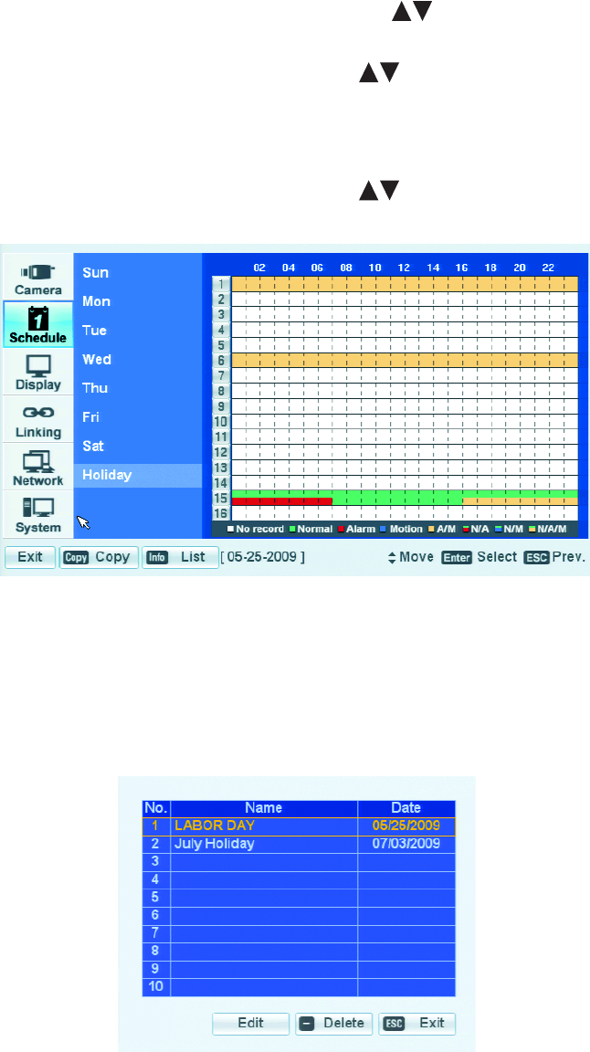
C2674M-C (7/09) 45
14. Alternatively, to view pre-existing holiday schedules, do one of the following:
• On the front panel, press the SHIFT button, and then press the INFO button.
• On the remote control, press the INFO button.
• Using the mouse, click Info.
The Holiday List dialog box opens.
a. On the front panel or remote control, press the up/down arrow buttons to highlight the desired schedule. Using the mouse,
click the schedule.
15. On the front panel or remote control, press the up/down arrow buttons to highlight Edit, and then press ENTER. Using the mouse,
click Edit. The selected schedule is displayed and the cursor is positioned in the first cell of channel 1.
EDITING A HOLIDAY SCHEDULE
1. On the front panel or remote control, press the up/down arrow buttons to highlight Holiday. Using the mouse, click Holiday. The
Holiday option is highlighted and the schedule grid is displayed.
Figure 37. Holiday Option Schedule Grid
2. To display the Holiday list, do one of the following:
• On the front panel, press the SHIFT button and then press the Info button.
• On the remote control, press the Info button.
• Using the mouse, click Info.
The Holiday List dialog box opens.
Figure 38. Holiday List Dialog Box
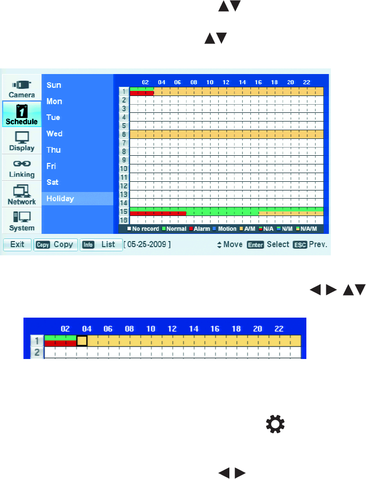
46 C2674M-C (7/09)
3. To edit a holiday schedule, do the following:
a. On the front panel or remote control, press the up/down arrow buttons to highlight a schedule. Using the mouse, click a
schedule.
b. On the front panel or remote control, press up/down arrow buttons to highlight Edit, and then press ENTER. Using the mouse,
click Edit. The selected schedule is displayed and the cursor is position at the first cell of channel 1.
Figure 39. Holiday Schedule
c. To edit the recording schedule on the front panel or remote control, press any of the arrow buttons and then press
ENTER to select the cells of the schedule grid. Using the mouse, click the cells of the schedule grid.
Figure 40. Editing a Holiday Schedule
4. Save the edited holiday schedule.
a. Do one of the following:
• On the front panel, press the MENU/ESC button or press the MENU/ESC button on the remote control until the
“Configuration data is changed. Save the new settings message?” dialog box is displayed.
• Using the mouse, click Exit. The “Configuration data is changed. Save the new settings?” dialog box is displayed.
b. On the front panel or remote control, press the left/right arrow buttons to highlight OK, and then press ENTER. Using the
mouse, click OK. The edited schedule is saved and the Live View mode is displayed.
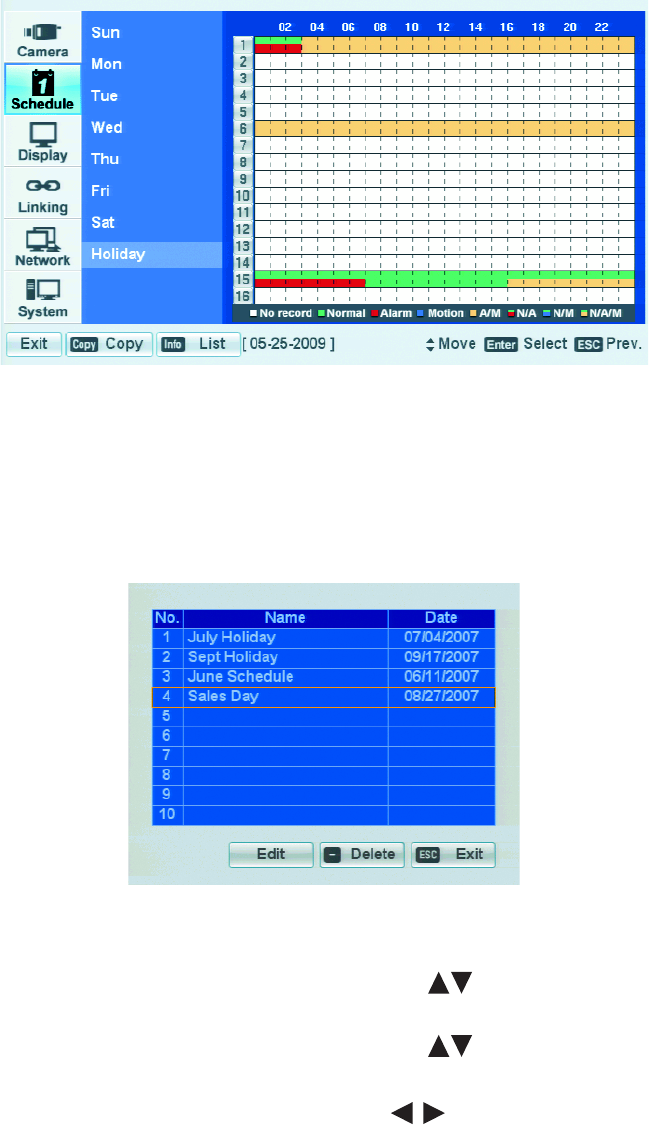
C2674M-C (7/09) 47
DELETING A HOLIDAY SCHEDULE
1. Select the Holiday option.
Figure 41. Holiday Option
2. To display the Holiday List dialog box and do one of the following:
• On the front panel, press the SHIFT button and then press the Info button.
• On the remote control, press the Info button.
• Using the mouse, click the Info button.
The Holiday List dialog box opens.
Figure 42. Holiday List Dialog Box
3. To delete a holiday schedule, do the following:
a. On the front panel or remote control, press the up/down arrow buttons to highlight a schedule. Using the mouse, click a
schedule.
b. On the front panel or remote control, press the up/down arrow buttons to highlight Delete, and then press ENTER. Using the
mouse, click Delete. The selected schedule is deleted from the list.
4. On the front panel or remote control, press the left/right arrow buttons to highlight Exit, and then press ENTER. Using the mouse,
click Exit. The List dialog box closes.

48 C2674M-C (7/09)
5. Save the revised Holiday list.
a. Do one of the following:
• On the front panel, press the MENU/ESC button or press the MENU/ESC button on the remote control until the
“Configuration data is changed. Save the new settings message?” dialog box is displayed.
• Using the mouse, click Exit. The “Configuration data is changed. Save the new settings?” dialog box is displayed.
b. On the front panel or remote control, press the left/right arrow buttons to highlight OK, and then press ENTER. Using the
mouse, click OK. The edited schedule is saved and the Live View mode is displayed.

C2674M-C (7/09) 49
Display Menu Setup
MAIN AND SPOT MONITORS
You can select the display language and configure the display settings to hide channel names and status information, specify the main and spot
monitor dwell time, and configure the spot monitor for covert operation. If a user is logged on with administrator-level permission and the Covert
Camera property is set to ON, video from cameras configured for covert operation is not displayed on the spot monitor. If the Covert Camera
property is set to OFF, video from cameras configured for covert operation is displayed on the spot monitor. Covert video is hidden from users
logged on with power- or normal-level permission, whether or not the spot monitor is configured for covert operation.
The DX4500/DX4600 supports 12 languages; English (United States) is the default language. You must log on with administrator level permission
to change the language. The following languages are supported:
• Chinese
• English (Default)
• French
•German
•Italian
• Japanese
• Korean
• Polish
• Portuguese
•Russian
• Spanish
•Turkish
1. On the front panel or remote control, press the up/down arrow buttons to select the Display menu option. Using the mouse, click
the Display menu option. The Display page opens, listing the available options.
Figure 43. Display Menu
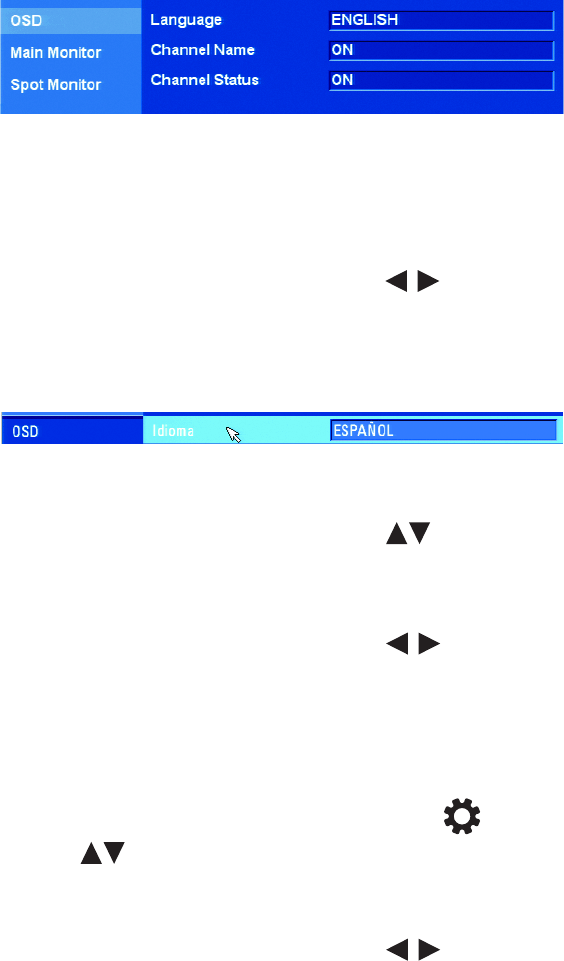
50 C2674M-C (7/09)
2. To change the language, on the front panel or remote control, press ENTER. Using the mouse, click the Display menu option. The OSD
property is highlighted, and its property settings are displayed. ENGLISH is the default language. The display language changes
immediately to reflect the language setting.
Figure 44. OSD Settings
3. To select a language, do the following:
a. On the front panel or remote control, press ENTER twice. Using the mouse, click the Language settings box.
The Language settings box is selected and the background changes color.
b. On the front panel or remote control, press the left/right arrow buttons . Using the mouse, right- or left-click in the entry box
to scroll through the languages.
c. Press ENTER on the front panel or remote control. Using the mouse, click the desired language from the list. The Language settings
box changes color again.
Figure 45. Changing the Language
4. To hide the channel name, do the following:
a. On the front panel or remote control, press the up/down arrow buttons to highlight Channel Name. Using the mouse, click
Channel Name.
b. On the front panel or remote control, press ENTER. Using the mouse, click the Channel Name settings box. The settings box changes
color.
c. On the front panel or remote control, press the left/right arrow buttons . Using the mouse, right- or left-click in the settings
box. The setting toggles to OFF.
d. On the front panel or remote control, press ENTER. Using the mouse, click Channel Name. The settings box changes color again.
5. Repeat step 4a through 4d to hide the channel status information.
6. To configure the main monitor dwell time, do the following:
a. On the front panel, press the MENU/ESC button or press the MENU/ESC button on the remote control, and then use the
up/down arrow buttons to highlight Main Monitor. Using the mouse, click Main Monitor. The Main Monitor option is
highlighted and the Dwell Time property is displayed.
b. Press ENTER on the front panel or remote control. Using the mouse, click Dwell Time. The settings box changes color.
c. On the front panel or remote control, press the left/right arrow buttons . Using the mouse, right- or left-click in the settings
box to display the dwell time you want.
d. Press ENTER on the front panel or remote control. Using the mouse, click Dwell Time. The settings box changes color again.
7. To configure the spot monitor dwell time, repeat steps 6a to 6d for the Spot Monitor.

C2674M-C (7/09) 51
8. To configure the spot monitor event pop-up setting, do the following:
a. On the front panel or remote control, use the up/down arrow buttons to highlight Event Popup. Using the mouse, click Event
Popup.
b. Press ENTER on the front panel or remote control. Using the mouse, click the Event Popup settings box. The settings box changes color.
c. To display the setting box on the front panel or remote control, press the left/right arrow buttons . Using the mouse, right- or
left-click in the settings box.
d. Press ENTER on the front panel or remote control. Using the mouse, click Event Popup. The settings box changes color again.
9. To configure the spot monitor for covert camera setting, do the following:
a. On the front panel or remote control, use the up/down arrow buttons to highlight Covert Camera. Using the mouse, click
Covert Camera.
b. Press ENTER on the front panel or remote control. Using the mouse, click the Covert Camera settings box. The settings box changes
color.
c. To display the setting box on the front panel or remote control, press the left/right arrow buttons . Using the mouse, right- or
left-click in the settings box.
d. Press ENTER on the front panel or remote control. Using the mouse, click Event Popup. The settings box changes color again.
10. Save the changes.
a. Do one of the following:
• On the front panel, press the MENU/ESC button or press the MENU/ESC button on the remote control until the
“Configuration data is changed. Save the new settings message?” dialog box is displayed.
• Using the mouse, click Exit. “The Configuration data is changed. Save the new settings?” dialog box is displayed.
b. On the front panel or remote control, press the left/right arrow buttons to highlight OK, and then press ENTER. Using the
mouse, click OK. The changes are saved and the Live View mode is displayed.
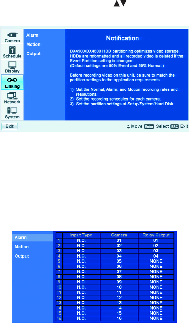
52 C2674M-C (7/09)
Linking Menu Setup
The pre- and post-event recording settings for alarms and motion are configured in the Record menu. For information about pre- and post-event
recording setup, refer to Schedule Menu Setup on page 37.
1. On the front panel or remote control, press the up/down arrow buttons to highlight the Linking menu option. Using the mouse, click
the Linking menu option. The linking options are displayed.
Figure 46. Linking Menu
ALARM INPUTS
The DX4508/DX4608/DX4608 support eight alarm inputs and two relay output; and the DX4516/DX4616 supports sixteen alarm inputs and four
relay outputs.
• One alarm input can be linked to one camera channel. One camera channel can be assigned to multiple alarm inputs.
• One alarm input can be linked to one relay output. One relay output can be assigned to multiple alarm inputs.
1. From the Linking menu, on the front panel or remote control, press ENTER. Using the mouse, click the Linking menu option. The Alarm
option is highlighted and the settings are displayed.
Figure 47. Property Option Settings
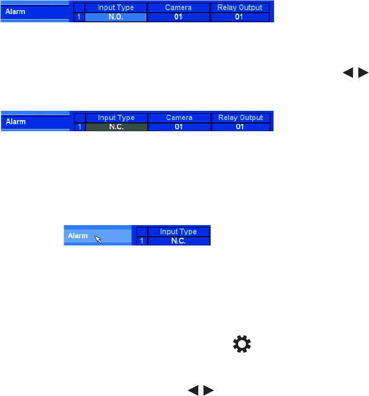
C2674M-C (7/09) 53
2. Change the Input Type.
a. Do one of the following:
• On the front panel or remote control, press ENTER. The Input Type settings box is highlighted.
Figure 48. Input Type Settings Box
• Using the mouse, click the Input Type, Camera, or Relay Output settings box. The settings box changes color.
b. On the front panel or remote control, press ENTER to select the settings box, and then press the left/right arrow buttons .
Using the mouse, click the settings box to display the desired setting.
Figure 49. Changing the Input Type
c. Do one of the following:
• On the front panel or remote control, press ENTER. The Input Type settings box changes color and the setting is selected.
• Using the mouse, click Alarm. The Input Type settings box changes color, the setting is selected, and the Alarm option is
highlighted.
Figure 50. Selecting the Input Type Settings Box
d. To configure more alarm inputs, repeat steps 2a to 2c.
e. Repeat the procedure in step 2 to configure the Camera settings and Relay Output settings.
3. Save the changes.
a. Do one of the following:
• On the front panel, press the MENU/ESC button or press the MENU/ESC button on the remote control until the
“Configuration data is changed. Save the new settings message?” dialog box is displayed.
• Using the mouse, click Exit. “The Configuration data is changed. Save the new settings?” dialog box is displayed.
b. On the front panel or remote control, press the left/right arrow buttons to highlight OK, and then press ENTER. Using the
mouse, click OK. The changes are saved and the Live View mode is displayed.
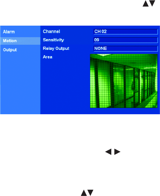
54 C2674M-C (7/09)
MOTION DETECTION
1. From the Setup widow, on the front panel or remote control, press the up/down arrow buttons to highlight Motion. Using the
mouse, click Motion. The Motion option is highlighted and the property settings are displayed.
Figure 51. Property Option Settings
2. To change a channel’s motion setting, do the following:
a. On the front panel and remote control, press ENTER. Using the mouse, click Channel. The Channel property is highlighted.
b. On the front panel or remote control use the left/right arrow buttons to navigate to a setting box, and then press ENTER.
Using the mouse, click the settings box to display the channel/camera name you want to configure. The settings box changes color
and the channels are displayed.
c. On the front panel or remote control, press ENTER. Using the mouse, click Channel. The Input Type settings box changes color and the
setting is selected.
3. To configure the sensitivity, press the up/down arrow buttons to highlight Sensitivity. Using the mouse, click Sensitivity and perform
the procedure in steps 2b and 2c.
The sensitivity settings are: OFF, 0 to 9, and HIGHEST. By default, the sensitivity is set to 5. The DVR provides a feature that gives a visual
indication that motion is being detected. The pixels on the screen change color where motion is detected. You can use this feature to
ensure that the optimal level of sensitivity is set for your application.
4. To configure the relay output, perform the procedure in step 3.
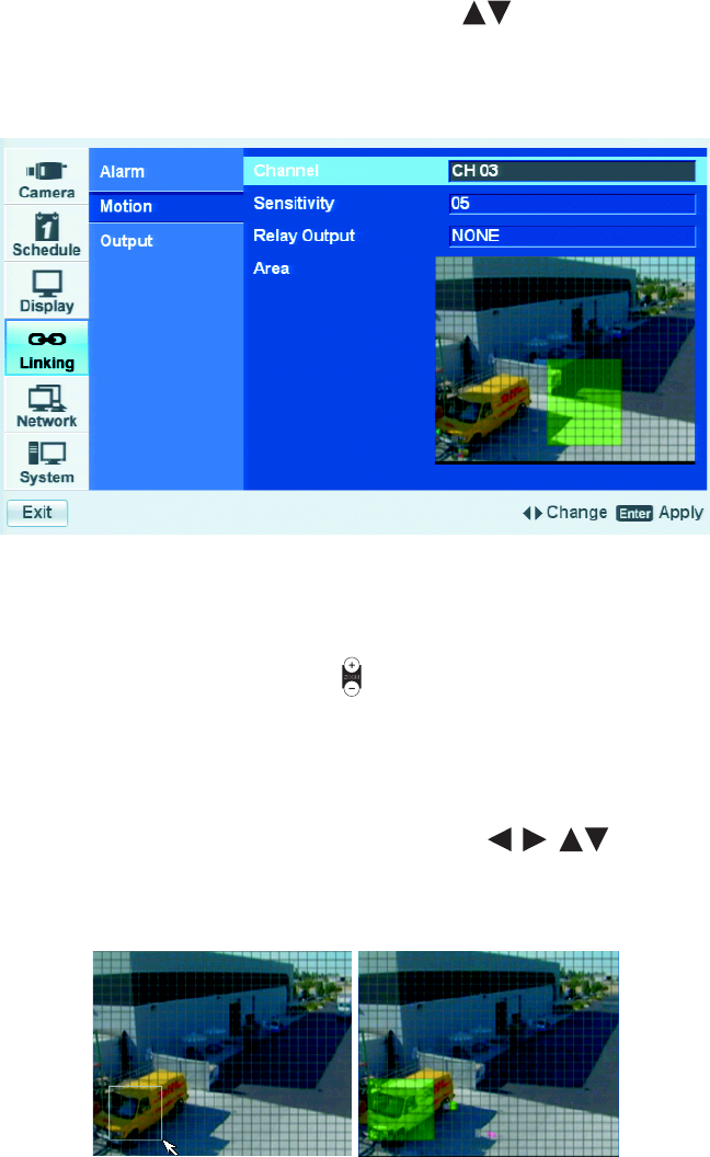
C2674M-C (7/09) 55
5. To configure the motion area, do the following:
a. On the front panel or remote control, press the up/down arrow buttons to highlight the Area option. Using the mouse, click the
Area option. The Area property is highlighted and motion detection can now be observed in the view window.
b. On the front panel or remote control, press ENTER. Using the mouse, click anywhere in the view window. The selection cursor is
placed in the first pixel of the view window.
Figure 52. Selecting the View Window
c. To clear the entire view window, do one of the following:
• On the front panel, press the SHIFT button and then press the ZOOM button.
• On the remote control, press the ZOOM- button .
• Using the mouse, click Clear All.
6. You can use the front panel or remote control to define the motion view area cell-by-cell, or you can use the mouse to click and drag to
define an area.
• To select a view area for motion detection, do one of the following:
– On the front panel or remote control, press any of the arrow buttons to highlight a cell in the motion detection
area, and then press ENTER. The selected cell turns green. Repeat this process until you have defined the motion detection area.
– If using the mouse, left-click and drag (diagonally up) an area, and then release the button. The area is selected and the cells turn
green.
Figure 53. Define and Select a Motion View Area
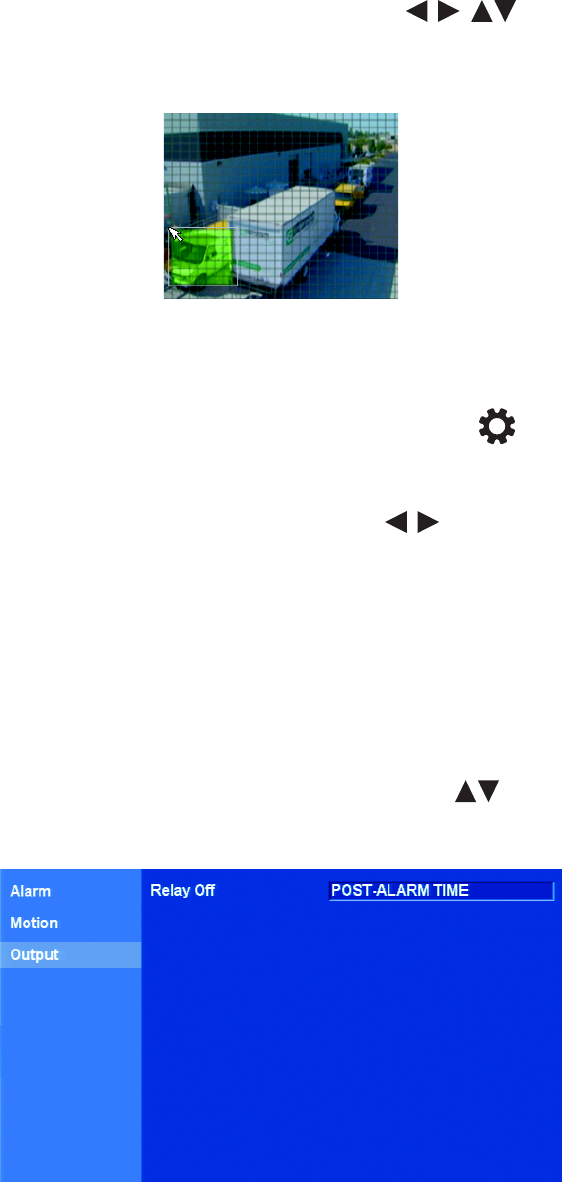
56 C2674M-C (7/09)
• To clear a selected view area, do one of the following:
– On the front panel or remote control, press any of the arrow buttons to highlight a selected cell in the motion
detection area, and then press ENTER. The cell is deselected. Repeat this process until you have deselected all of the cells.
– If using the mouse, left-click and drag (diagonally down) an area, and then release the button. The area is selected and the cells
turn green.
Figure 54. Define and Select a Motion View Area
7. Save the changes.
a. Do one of the following:
• On the front panel, press the MENU/ESC button or press the MENU/ESC button on the remote control until the
“Configuration data is changed. Save the new settings message?” dialog box is displayed.
• Using the mouse, click Exit. “The Configuration data is changed. Save the new settings?” dialog box is displayed.
b. On the front panel or remote control, press the left/right arrow buttons to highlight OK, and then press ENTER. Using the
mouse, click OK. The changes are saved and the Live View mode is displayed.
RELAY OUTPUTS
You can configure how the relay outputs are controlled: automatic or manual. The Relay Off setting applies globally for all relay outputs. The
Relay Off option does not control the actual alarm record function. Turning off the relay output does not terminate the alarm record mode.
•Automatic: Relay out is turned off when the post-alarm time expires. This setting is configured individually for each channel. For
information about configuring post-alarm time, refer to Schedule Menu Setup on page 37.
•Manual: Relay Output is turned off from the front panel, remote control, or GUI.
1. From the Setup widow, on the front panel or remote control, press the up/down arrows to highlight Output. Using the mouse, click
Output. The Output option is highlighted and the property setting is displayed.
Figure 55. Property Option Settings
2. To configure how the relay outputs respond when the alarm record mode stops, press ENTER on the front panel and remote control. Using
the mouse, click Channel. The Relay Off property is highlighted.

C2674M-C (7/09) 57
3. To display the setting you want to configure, on the front panel or remote control, use the left/right arrow buttons to navigate
to the settings box. Then press ENTER to select the desired settings. Press ENTER and use the left/right arrow buttons . Using
the mouse, click the settings box to display the setting you want to configure: POST-ALARM TIME (default) or ALARM
ACKNOWLEDGED. The settings box changes color.
4. On the front panel or remote control, press ENTER. Using the mouse, click Relay Off. The settings box changes color.
5. Save the changes.
a. Do one of the following:
• On the front panel, press the MENU/ESC button or press the MENU/ESC button on the remote control until the
“Configuration data is changed. Save the new settings message?” dialog box is displayed.
• Using the mouse, click Exit. “The Configuration data is changed. Save the new settings?” dialog box is displayed.
b. On the front panel or remote control, press the left/right arrow buttons to highlight OK, and then press ENTER. Using the
mouse, click OK. The changes are saved and the Live View mode is displayed.
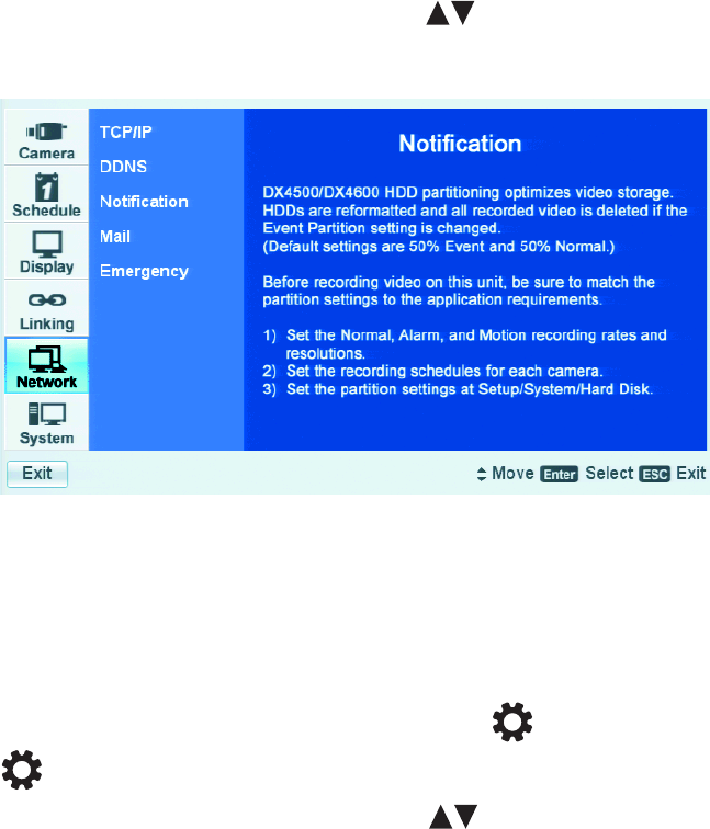
58 C2674M-C (7/09)
Network Menu Setup
If you are installing the DX4500/DX4600 in a network environment, you must configure the DVR network settings to use the following:
•Client software application: Allows you to log on to, operate, and administer up to sixteen DX4500/DX4600 server systems
simultaneously from a remote location. the DX4500/DX4600 server supports a total five simultaneous connections when using the client
and Web client applications. For more information about the remote client software application, refer to the DX4500/DX4600 Client
Operation and Programming manual.
•Web client applications: Allows you to view live video and operate pan, tilt, and zoom (PTZ) features of cameras attached to a DX4500/
DX4600. You can remotely monitor up to 16 cameras from the DX4500/DX4600. The DX4500/DX4600 supports a total five simultaneous
connections when using the client and Web client applications.
•Network Time Protocol (NTP): Allows you to use a public or private time server.
•Software update over the network: Allows you to update the server software over the network.
•Mail notification: Sends e-mail notification if an event occurs. For example, if an alarm or motion is detected, you will receive a
notification that the administrator level password has been changed and so forth.
•Emergency Agent: Installed as part of the Client application, this application works with DX4500/DX4600 servers. If a server unit detects
an event (alarm, motion, disk full, administrator password change, and so forth), an event message is sent to the Emergency Agent. The
message displays for 5 seconds in the lower-right area of the remote client PC screen.
The DX4500/DX4600 must be turned on, connected to a network, and you must be logged on at the administrator level to configure network
software settings. You must restart the DVR for the network configuration changes to take effect. Be sure you are not recording video that cannot
be interrupted before you change network settings.
1. On the front panel or remote control, press the up/down arrow buttons to highlight the Linking menu option. Using the mouse, click
the Linking menu option. The Camera options are displayed.
Figure 56. Network Menu
TCP/IP
To configure the TCP/IP network settings:
1. Log on to the DVR at the administrator level. The DVR application window opens.
2. On the front panel, press the MENU/ESC button or press the MENU/ESC button on the remote control. Using the mouse, click the
Setup icon . The Setup window opens to the Camera menu, displaying the options.
3. On the front panel or remote control, press the up/down arrow buttons to select the Network menu option. Using the mouse, click
the Network menu option. The Network page opens.
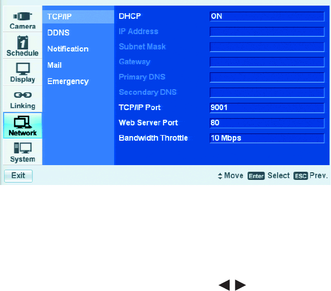
C2674M-C (7/09) 59
4. On the front panel or remote control, press ENTER. Using the mouse, click TCP/IP. The TCP/IP properties are displayed.
Figure 57. TCP/IP Properties
5. You can configure the TCP/IP settings to support your application.
a. On the front panel or remote control, press ENTER. Using the mouse, click DHCP. The settings for the selected property are
highlighted.
b. On the front panel or remote control, press ENTER. Using the mouse, click the property setting. The settings box changes color.
c. On the front panel or remote control, press the left/right arrow buttons . Using the mouse, right- or left-click in the settings
box to change the value.
d. On the front panel or remote control, press ENTER. Using the mouse, click the setting (for example, DHCP) to accept the change. The
settings box changes color.
e. Repeat steps 5a through 5d to configure any additional settings required for your network. If the TCP/IP DHCP setting is set to OFF, the
following settings are available:
•IP Address: Enter the static IP address (if used by your network).
•Subnet Mask: Enter the IP address of the subnet mask.
•Gateway: Enter the IP address for the Internet gateway server. On smaller systems, this will be the IP address of the DX4500/
DX4600. On larger systems, there might be a gateway server.
•Primary DNS Server: Verify the name of the dynamic domain name system (DDNS).
•Secondary DNS Server: Enter the IP address of the backup domain name system (DNS) server that the DX4500/DX4600 will
use to convert names to IP addresses. This server is used if the primary DNS server fails. If you intend to use the DDNS server,
you do not need to enter a DNS server.
•TCP/IP Port: The default port number is 9001.
•Web Server Port: Enter the port number that the Web client will use to communicate with the DX4500/DX4600 over the
Internet. The default port number is 80.
WARNING: If you use the Web client to access the DX4500/DX4600 and you change the port number, you must update the IP
address or the Web address to include the new port number. For example, the revised IP address would be
http://192.168.0.40:8080, where 8080 is the revised port number.
•Bandwidth Throttle: Select the network bandwidth throttle to limit the amount of network resources allocated to client
connections. The default bandwidth throttle is 10 Mbps.
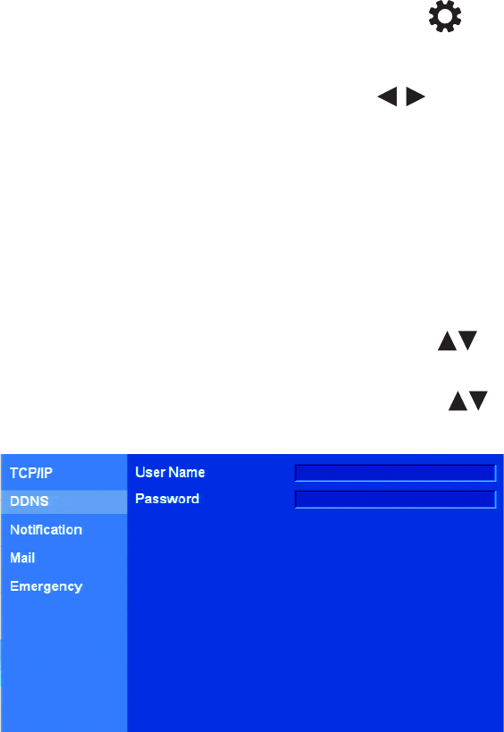
60 C2674M-C (7/09)
6. Save the changes.
a. Do one of the following:
• On the front panel, press the MENU/ESC button or press the MENU/ESC button on the remote control until the
“Configuration data is changed. Save the new settings message?” dialog box is displayed.
• Click Exit. “The Configuration data is changed. Save the new settings?” dialog box is displayed.
• On the front panel or remote control, press the left/right arrow buttons to highlight OK, and then press ENTER. Using
the mouse, click OK. The changes are saved and the Live View mode is displayed.
DDNS
The DX4500/DX4600 Dynamic DNS (DDNS) feature uses the services provided by No-IP™. Prior registration with No-IP is required before
configuring the DVR.
The DDNS feature uses port 8245 provided by No-IP (http://www.no-ip.com/). In this case, if the DVR is installed in a network that has a firewall,
port 8245 has to be opened to allow DDNS data to get through the firewall. For information about setting up the firewall, refer to your network
administrator or network service provider.
1. In the Setup window, on the front panel or remote control, press the up/down arrow buttons to select the Network menu option.
Using the mouse, click the Network menu option. The Network page opens.
2. On the front panel or remote control, press ENTER, and then press the up/down arrow buttons to select DDNS. Using the mouse,
click DDNS. The DDNS properties are displayed.
Figure 58. Configuring DDNS
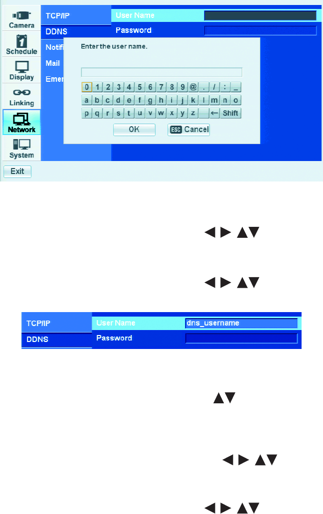
C2674M-C (7/09) 61
3. To enter the DDNS user name.
a. On the front panel or remote control, press ENTER. Using the mouse, click User Name. The settings for the selected property are
highlighted.
b. On the front panel or remote control, press ENTER. Using the mouse, click the property setting. The settings box changes color and the
virtual keyboard opens.
Figure 59. DDNS Virtual Keyboard
c. Enter the registered DDNS user name (use the Shift button on the virtual keyboard) to display uppercase and lowercase characters.
On the front panel or remote control, press any of the arrow buttons to move the cursor to a character, and press
ENTER. Using the mouse, click a character. The selected character appears in the text entry box.
d. Repeat step 4c to enter the remaining characters of the user name.
e. On the front panel or remote control, press any of the arrow buttons to highlight OK, and then press ENTER. Using
the mouse, click OK. The user name is displayed in the User Name settings box.
Figure 60. DDNS User Name
4. To enter the DDNS password.
a. On the front panel or remote control, press the up/down arrow buttons to highlight Password. Using the mouse, click
Password.
b. On the front panel or remote control, press ENTER. Using the mouse, click the settings box. The virtual keyboard opens.
c. To enter the DDNS password:
(1) On the front panel or remote control, press any of the arrow buttons to move the cursor to a character, and
then press ENTER. Using the mouse, click a character. An asterisk is displayed in the text entry box for each character entered.
(2) Repeat step 4c(1) to enter the remaining password characters.
d. On the front panel or remote control, press any of the arrow buttons to highlight OK, and then press ENTER. Using
the mouse, click OK. Asterisks are displayed in the Password settings box.
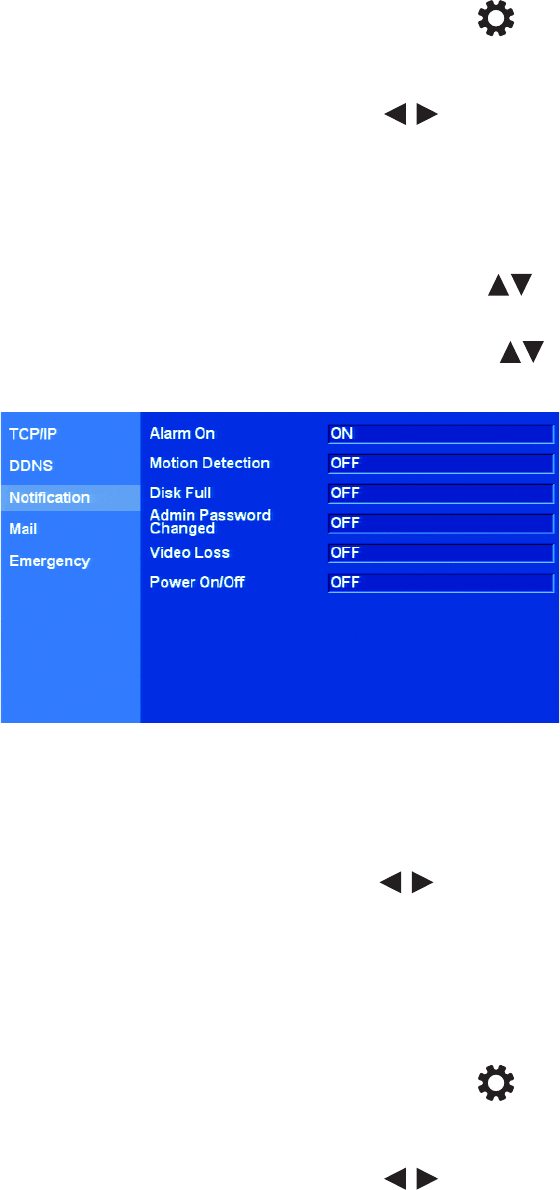
62 C2674M-C (7/09)
5. Save the changes.
a. Do one of the following:
• On the front panel, press the MENU/ESC button or press the MENU/ESC button on the remote control until the
“Configuration data is changed. Save the new settings message?” dialog box is displayed.
• Click Exit. “The Configuration data is changed. Save the new settings?” dialog box is displayed.
b. On the front panel or remote control, press the left/right arrow buttons to highlight OK, and then press ENTER. Using the
mouse, click OK. The changes are saved and the Live View mode is displayed.
NOTIFICATION
The DX4500/DX4600 notification feature allows you to specify the events that generate notification.
1. In the Setup window, on the front panel or remote control, press the up/down arrow buttons to select the Network menu option.
Using the mouse, click the Network menu option. The Network page opens.
2. On the front panel or remote control, press ENTER, and then press the up/down arrow buttons to select Notification. Using the
mouse, click Notification. The Notification properties are displayed.
Figure 61. Notification Option Settings
3. To enable alarm event notification:
a. On the front panel or remote control, press ENTER twice. Using the mouse, click the language settings box. The Alarm On settings box
changes color. By default, all events are set to OFF.
b. On the front panel or remote control, press the left/right arrow buttons . Using the mouse, right- or left-click the settings box.
The setting toggles to ON.
c. Press ENTER on the front panel or remote control. Using the mouse, click Alarm On. The settings box changes color again.
4. To enable other events for notification, perform the same to access the option’s settings box and select ON.
5. Save the changes.
a. Do one of the following:
• On the front panel, press the MENU/ESC button or press the MENU/ESC button on the remote control until the
“Configuration data is changed. Save the new settings message?” dialog box is displayed.
• Using the mouse, click Exit. The “Configuration data is changed. Save the new settings?” dialog box is displayed.
b. On the front panel or remote control, press the left/right arrow buttons to highlight OK, and then press ENTER. Using the
mouse, click OK. The changes are saved and the Live View mode is displayed.
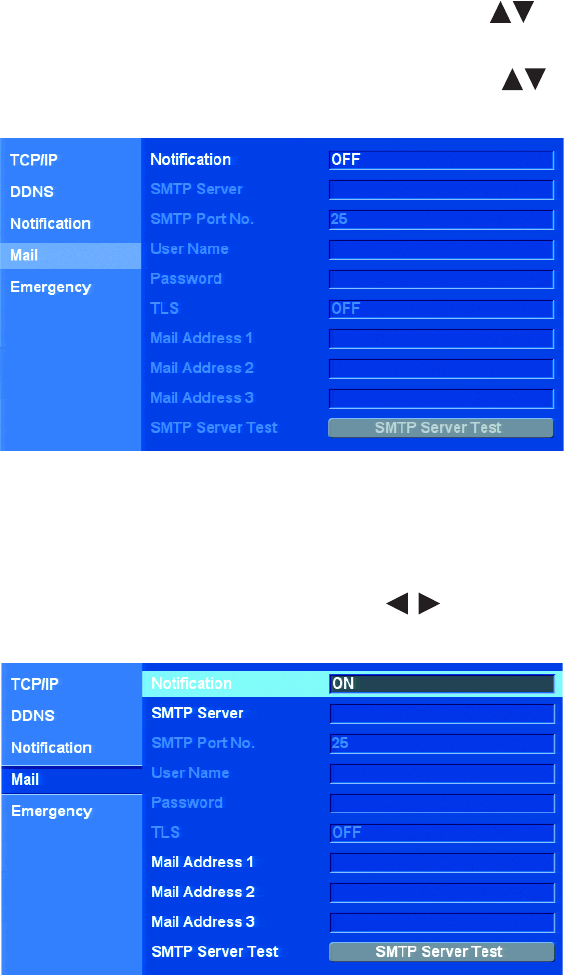
C2674M-C (7/09) 63
MAIL
The DX4500/DX4600 mail feature sends an e-mail notification to all designated users when an event is detected. (for example, an alarm or
motion event is detected and the ADMINISTRATOR password is changed) This event must be specified using the notification option. For
information about configuring the notification option, refer to Notification on page 62.
The mail feature is configured and operates independently of the emergency agent feature. For information about setting up the emergency
notification feature, refer to Emergency Notification on page 66.
1. In the Setup window, on the front panel or remote control, press the up/down arrow buttons to select the Network menu option.
Using the mouse, click the Network menu option. The Network page opens.
2. On the front panel or remote control, press ENTER, and then press the up/down arrow buttons to select Mail. Using the mouse,
click Mail. The Mail properties are displayed. By default, notification is set to OFF.
Figure 62. Mail Option Properties
3. To enable mail notification:
a. On the front panel or remote control, press ENTER twice. Using the mouse, click the language settings box. The notification settings
box changes color.
b. On the front panel or remote control, press the left/right arrow buttons. . Using the mouse, right- or left-click in the settings
box to toggle the setting to ON. The SMTP server and mail address settings boxes are available.
Figure 63. Setting Notification
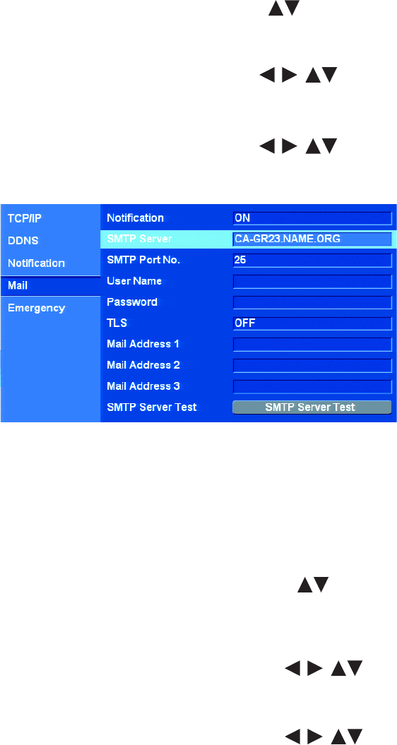
64 C2674M-C (7/09)
4. To configure the SMTP server settings.
a. On the front panel or remote control, press ENTER. Using the mouse, click Notification. The settings box changes color.
b. On the front panel or remote control, press the up/down arrow buttons to highlight SMTP Server and then press ENTER. Using
the mouse, click SMTP Server and then click the settings box. The virtual keyboard opens.
c. Enter the SMTP server name or IP address (use the Shift button on the virtual keyboard to display uppercase or lowercase characters.)
On the front panel or remote control, press any of the arrow buttons to move the cursor to a character, and press
ENTER. Using the mouse, click a character. The selected character appears in the text entry box.
d. Repeat step 4c to enter the remaining characters of the user name.
e. On the front panel or remote control, press any of the arrow buttons to highlight OK, and then press ENTER. Using
the mouse, click OK. The SMTP server name or IP address is displayed in the SMTP Server settings box and the SMTP Port No., User
Name, Password, and TLS properties are available.
Figure 64. Configuring the SMTP Server Name or IP Address
5. Enter the SMTP Port Number, User Name, Password, and TTL setting.
a. The default SMTP port number is 25. Valid SMTP port numbers are 25 or 1025 to 65535.
• To change the port number, go to step 5b.
• To accept the default setting, go to step 5c.
b. To enter a different port number, do the following:
(1) On the front panel or remote control, press the up/down arrow buttons to highlight SMTP Port Number. Using the
mouse, click SMTP Port Number.
(2) On the front panel or remote control, press ENTER. Using the mouse, click the settings box. The virtual keyboard opens. Valid
SMTP port numbers are 25 or 1025 to 65535.
(3) On the front panel or remote control, press any of the arrow buttons to move the cursor to a character, and
then press ENTER. Using the mouse, click a character.
(4) Repeat step 5b(3) to enter the remaining characters.
(5) On the front panel or remote control, press any of the arrow buttons to highlight OK, and then press ENTER.
Using the mouse, click OK. The new port number is displayed in the settings box.
c. To enter the SMTP server user name and the password, perform the procedure in step 5b for each respective field.
d. Transport Layer Security (TLS). By default, TLS is set to OFF. Use the front panel, remote control, or mouse to change the setting to ON.
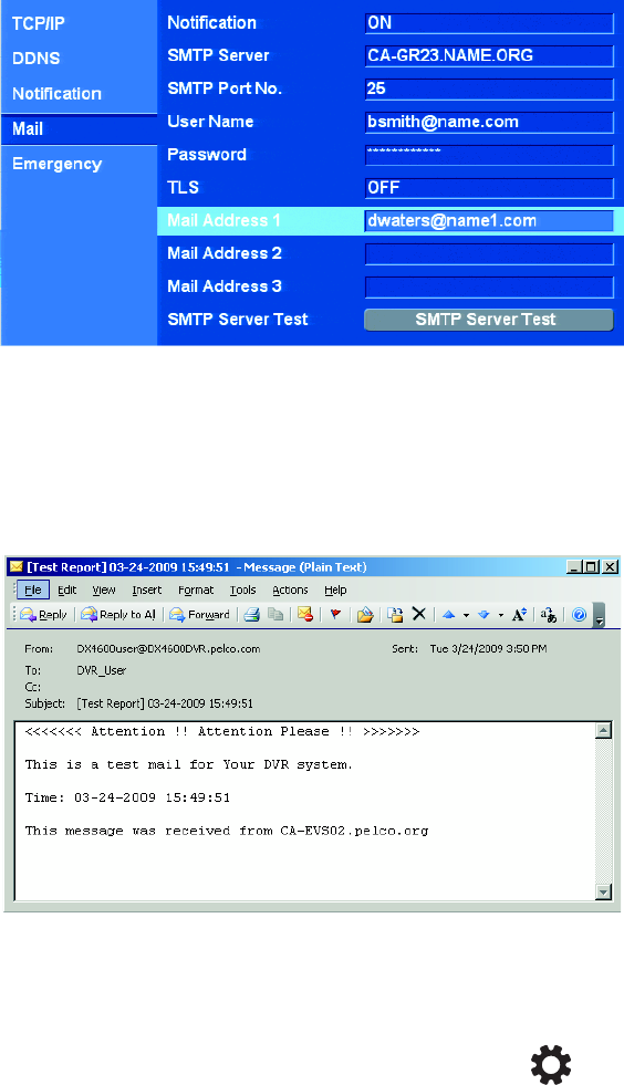
C2674M-C (7/09) 65
6. As many as three email addresses can be configured for mail notification. Perform the procedure in step 5b for entering the e-mail
addresses. Repeat the process for each subsequent e-mail address.
Figure 65. SMTP Configuration and E-mail Address
7. To verify the SMTP server connection, on the front panel or remote control, highlight E-mail Test. Then press ENTER. Using the mouse, click
E-mail Test, and then click the E-mail Test button.
The DVR displays a pass or fail message. The “Test email sent successfully” message indicates a successful SMTP server configuration. A
test e-mail message is also sent to each e-mail address. Verify with each user that a test e-mail message was received. Refer to Figure 66.
Figure 66. Test E-mail Message
8. Save the changes.
a. Do one of the following:
• On the front panel, press the MENU/ESC button or press the MENU/ESC button on the remote control until the
“Configuration data is changed. Save the new settings message?” dialog box is displayed.
• Using the mouse, click Exit. The “Configuration data is changed. Save the new settings?” dialog box is displayed.
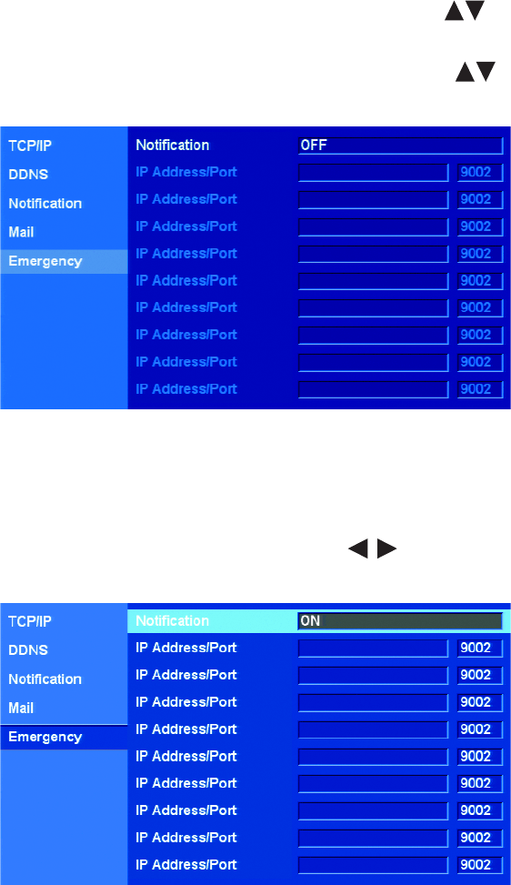
66 C2674M-C (7/09)
EMERGENCY NOTIFICATION
The DX4500/DX4600 emergency notification feature sends an emergency report to the designated computer on which the Emergency Agent
application is running (for example, alarm or motion event is detected and the ADMINISTRATOR password is changed). This event must be
specified using the notification option. For information about configuring the notification option, refer to Notification on page 62.
The emergency notification feature is configured and operates independently of the mail feature. The Emergency Agent application is installed
on the remote client computer and is used to display and administer emergency reports. In this case, the DVR can be configured to send
emergency reports but not mail. For information about setting up the mail feature, refer to Mail on page 63.
1. In the Setup window, on the front panel or remote control, press the up/down arrow buttons to select the Network menu option.
Using the mouse, click the Network menu option. The Network page opens.
2. On the front panel or remote control, press ENTER, and then press the up/down arrow buttons to select Emergency. Using the
mouse, click Emergency. The Emergency properties are displayed. By default, notification is set to OFF.
Figure 67. Emergency Option Properties
3. To enable emergency notification:
a. On the front panel or remote control, press ENTER twice. Using the mouse, click the Notification settings box. The settings box
changes color.
b. On the front panel or remote control, press the left/right arrow buttons . Using the mouse, right- or left-click the settings box
to toggle the setting to ON. The IP Address/Port boxes are available.
Figure 68. Enabling Emergency Notification
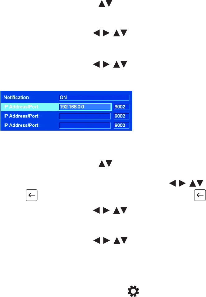
C2674M-C (7/09) 67
4. To configure a destination computer IP address.
a. On the front panel or remote control, press ENTER. Using the mouse, click Notification. The settings box changes color.
b. On the front panel or remote control, press the up/down arrow buttons to highlight IP Address/Port and press ENTER. Using
the mouse, click IP Address/Port, and then click the settings box. The virtual keyboard opens.
c. Enter the destination remote computer IP address.
On the front panel or remote control, press any of the arrow buttons to move the cursor to a character, and then
press ENTER. Using the mouse, click a character. The selected character appears in the text entry box.
d. Repeat step 4c to enter the remaining characters of the IP address.
e. On the front panel or remote control, press any of the arrow buttons to highlight OK, and then press ENTER. Using
the mouse, click OK. The remote computer IP address is displayed in the IP Address/Port settings box.
f. Repeat this procedure to configure additional IP addresses.
Figure 69. Configuring Remote Computer IP Address
5. The default emergency notification port number is 9002. To enter a different emergency notification port number, perform the following:
a. On the front panel or remote control, press the up/down arrow buttons to highlight IP Address/Port, and then press ENTER.
Using the mouse, click IP Address/Port. The virtual keyboard is displayed and the current port number is displayed in the entry box.
b. To delete the existing port number, on the front panel or remote control, press the up/down arrow buttons to move
the cursor to the backspace button , and press ENTER to delete the existing port number. Using the mouse, click .
c. On the front panel or remote control, press any of the arrow buttons to move the cursor to a character, and then
press ENTER. Using the mouse, click a character.
d. Repeat step 5b(3) to enter the remaining characters.
e. On the front panel or remote control, press and of the arrow buttons to highlight OK, and then press ENTER. Using
the mouse, click OK. The new port number is displayed in the settings box.
f. Repeat step 5b(1) through 5b(5) to change the port number for another IP Address/Port option.
6. Save the changes.
a. Do one of the following:
• On the front panel, press the MENU/ESC button or press the MENU/ESC button on the remote control until the
“Configuration data is changed. Save the new settings message?” dialog box is displayed.
• Using the mouse, click Exit. The “Configuration data is changed. Save the new settings?” dialog box is displayed.
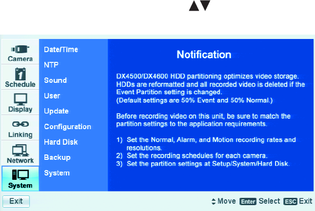
68 C2674M-C (7/09)
System Menu Setup
The DX4500/DX4600 system settings should be configured before the unit is put into service. Some of the settings affect how video data is
stored and backed up, and how the unit is operated and administered from a remote client application.
•Date/Time: Establishes the time frame for configuring recording schedules and automated backup. Also provides the time stamp for
recorded video, mail and emergency notification.
•Network Time Protocol (NTP): Allows you to use a public or private time server.
•User: Allows you to create user accounts for local and remote system operation and administration.
•Update: Supports updating DX4500/DX4600 software over the network.
•Backup: Schedules the automatic backup of recorded video.
The DX4500/DX4600 must be turned on, connected to a network, and you must be logged on at the administrator level to configure network
software settings. You must restart the DVR for any network configuration changes to take effect. Be sure you are not recording video that
cannot be interrupted before you change the network settings.
1. On the front panel or remote control, press the up/down arrow buttons to highlight the System menu option. Using the mouse, click
system menu options. The System options are displayed.
Figure 70. System Menu
DATE AND TIME
The System menu contains the Date/Time configuration option.
•Date: Sets the date and establishes the DVR’s internal calendar for all recorded video.
•Time: Sets the system time and establishes the time for all recorded video.
•Date Format: Selects the date format for the displayed date and establishes the saved video format as it is recorded. Choices are
MM/DD/YYYY, DD/MM/YYYY, and YYYY/MM/DD.
•Time Format: Sets the display time format and establishes the format that is saved video format as it is recorded. Choices are 12-and
24-hour time format.
•Time Zone: Selects the time zone in which the DX4500/DX4600 is located. Time zones are determined based on the number of hours by
which they are offset from the Greenwich Mean Time (GMT).
•Daylight Saving: Ensures that recorded video displays the correct time, reflecting the annual change to daylight saving time. Select this
setting if the DX4500/DX4600 is located in a state or country that observes daylight saving time.
You must configure daylight saving time on both the DX4500/DX4600 and the computer on which the remote client application is running.
Configure the time zone on the remote client system, using the System menu in the Setup window. For information about configuring the
time zone on the remote client PC, refer to the client operation manual.
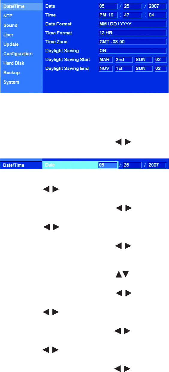
C2674M-C (7/09) 69
1. From the System menu, on the front panel or remote control, press ENTER. Using the mouse, click the Date/Time option. The Date/Time
settings are displayed; the default date format is MM/DD/YYYY.
Figure 71. Date/Time Settings
2. Select the date.
a. On the front panel or remote control, press ENTER twice. Using the mouse, click the month settings box. The month settings box
changes color.
b. On the front panel or remote control, press the left/right arrow buttons to display the desired month, and then press ENTER.
Using the mouse, click the settings box.
Figure 72. Date Settings Entry Box
c. Press the left/right arrow buttons to highlight the day settings box and press ENTER. Using the mouse, click the day settings
box. The day settings box changes color.
d. On the front panel or remote control, press the left/right arrow buttons to display the desired date, and then press ENTER.
Using the mouse, click the settings box.
e. Press the left/right arrow buttons to highlight the year settings box press ENTER. Using the mouse, click the year settings
box. The year settings box changes color.
f. On the front panel or remote control, press the left/right arrow buttons to display the year, and then press ENTER. Using the
mouse, click the settings box.
3. Select the time.
a. On the front panel or remote control, press the up/down arrow buttons to highlight the Time property, and then press ENTER.
Using the mouse, click the hour settings box. The settings box changes color.
b. On the front panel or remote control, press the left/right arrow buttons to display the desired hour, and then press ENTER.
Using the mouse, click the settings box.
c. Press the left/right arrow buttons to highlight the minutes settings box and press ENTER. Using the mouse, click the minutes
settings box. The minutes settings box changes color.
d. On the front panel or remote control, press the left/right arrow buttons to display the desired minute, and then press ENTER.
Using the mouse, click the settings box.
e. Press the left/right arrow buttons to highlight the seconds settings box and press ENTER. Using the mouse, click the seconds
settings box. The seconds settings box changes color.
f. On the front panel or remote control, press the left/right arrow buttons to display the desired second, and then press ENTER.
Using the mouse, click the settings box.

70 C2674M-C (7/09)
4. Set the date format.
a. On the front panel or remote control, press the up/down arrow buttons to highlight the Date Format property, and then press
ENTER. Using the mouse, click the Date Format settings box. The settings box changes color.
b. On the front panel or remote control, press the left/right arrow buttons to display the date format, and then press ENTER.
Using the mouse, click the settings box.
5. Set the time format.
a. On the front panel or remote control, press the up/down arrow buttons to highlight Time Format, and then press ENTER. Using
the mouse, click the Time Format settings box. The settings box changes color.
b. On the front panel or remote control, press the left/right arrow buttons to display the time format, and then press ENTER.
Using the mouse, click the settings box.
6. Set the time zone.
a. On the front panel or remote control, press the up/down arrow buttons to highlight Time Zone and then press ENTER. Using
the mouse, click the Time Zone settings box. The settings box changes color.
b. On the front panel or remote control, press the left/right arrow buttons to display the time zone, and then press ENTER.
Using the mouse, click the settings box.
7. Do one of the following:
• To configure DST, refer to Configuring Daylight Saving on page 71.
• If you do not want to configure DST, go to step 8.
8. Save the changes.
a. Do one of the following:
• On the front panel, press the MENU/ESC button or on the remote control press the MENU/ESC button until the
“Configuration data is changed. Save the new settings message?” dialog box is displayed.
• Using the mouse, click Exit. The “Configuration data is changed. Save the new settings?” dialog box is displayed.
b. On the front panel or remote control, press the left/right arrow buttons to highlight OK, and then press ENTER. Using the
mouse, click OK. The changes are saved and the live view mode is displayed.
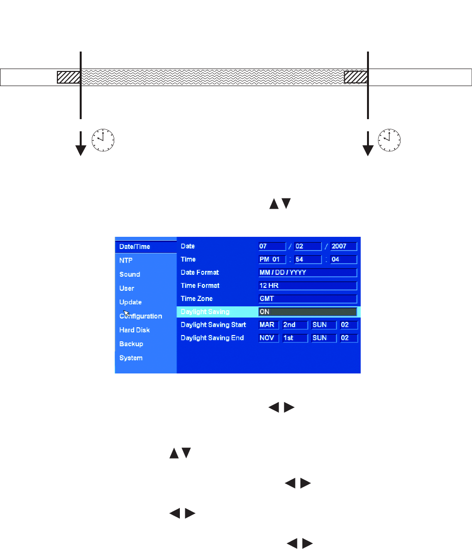
C2674M-C (7/09) 71
CONFIGURING DAYLIGHT SAVING
The DVR has the following conditions when the DST feature is used:
• Daylight Saving OFF: By default, the Daylight Saving feature is set to OFF. In this case, there is no change in the system time stamp for
recorded data throughout the year. The effective date is set using the Date, Time, Date Format, and Time Zone options.
• Daylight Saving OFF, but later changed to ON: For example, the DVR is installed in a location where DST is already in observance and the
DVR’s time is set to the local time. Sometime in the future, the Daylight Savings option is set to ON. In this case, there is no change in the
system time stamp for recorded data. When the Daylight Saving End date and time occur, the unit’s time goes back one hour.
Figure 73. DST Time Shift
1. On the front panel or remote control, press the up/down arrow buttons to highlight Daylight Saving, and then press ENTER. Using
the mouse, click the Daylight Saving settings box. The settings changes color.
Figure 74. Daylight Saving Settings
2. On the front panel or remote control, press the left/right arrow buttons to change the setting to ON, and then press ENTER. Using
the mouse, click the settings box.
3. To select the Daylight Saving Start date.
a. Press the up/down arrow buttons to highlight Daylight Saving Start, and then press ENTER. Using the mouse, click the
Daylight Saving Start settings box. The day settings box changes color.
b. On the front panel or remote control press the left/right arrow buttons to display the desired month, and then press ENTER.
Using the mouse, click the settings box.
c. Press the left/right arrow buttons to highlight the week settings box, and then press ENTER. Using the mouse, click the
settings box. The settings box changes color.
d. On the front panel or remote control, press the left/right arrow buttons to display the desired week, and then press ENTER.
Using the mouse, click the settings box.
DST (Daylight Saving Time) ON
1:00 am
1:59 am 1:59 am
3:00 am
Fall Season = DST PFF
November, 1st SundayMarch, 2nd Sunday
Example: Based on Pacific time zone (GMT-8)

72 C2674M-C (7/09)
e. Press the left/right arrow buttons to highlight the day settings box, and then press ENTER. Using the mouse, click the day
settings box. The settings box changes color.
f. On the front panel or remote control, press the left/right arrow buttons to display the desired name of the day, and then
press ENTER. Using the mouse, click the settings box.
g. Press the left/right arrow buttons to highlight the hour of the day settings box, and then press ENTER. Using the mouse, click
the day settings box. The settings box changes color.
h. On the front panel or remote control, press the left/right arrow buttons to display the desired hour of the day, and then press
ENTER. Using the mouse, click the settings box.
4. To select the Daylight Saving End date.
a. Press the up/down arrow buttons to highlight Daylight Saving End, and then press ENTER. Using the mouse, click the daylight
saving end settings box. The day settings box changes color.
b. On the front panel or remote control, press the left/right arrow buttons to display the desired month, and then press ENTER.
Using the mouse, click the settings box.
c. Press the left/right arrow buttons to highlight the week settings box, and then press ENTER. Using the mouse, click the
settings box. The settings box changes color.
d. On the front panel or remote control, press the left/right arrow buttons to display the desired week, and then press ENTER.
Using the mouse, click the settings box.
e. Press the left/right arrow buttons to highlight the day settings box, and then press ENTER. Using the mouse, click the day
settings box. The settings box changes color.
f. On the front panel or remote control, press the left/right arrow buttons to display the desired name of the day, and then
press ENTER. Using the mouse, click the settings box.
g. Press the left/right arrow buttons to highlight the hour of the day settings box, and then press ENTER. Using the mouse, click
the hour of the day settings box. The settings box changes color.
h. On the front panel or remote control, press the left/right arrow buttons to display the desired hour of the day, and then press
ENTER. Using the mouse, click the settings box.
i. Press ENTER on the front panel or remote control. If using the mouse, click Daylight Saving End. The settings box changes color.
5. To save the changes.
a. Do one of the following:
• On the front panel, press the MENU/ESC button or on the remote control press the MENU/ESC button until the
“Configuration data is changed. Save the new settings message?” dialog box is displayed.
• Using the mouse, click Exit. The “Configuration data is changed. Save the new settings?” dialog box is displayed.
b. On the front panel or remote control, press the left/right arrow buttons to highlight OK, and then press ENTER. Using the
mouse, click OK. The changes are saved and the live view mode is displayed.
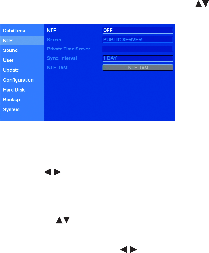
C2674M-C (7/09) 73
NTP
The internal time of the DX4500/DX4600 can be synchronized with an external time source using the NTP Date/Time configuration option.
•NTP: Sychronizes the DVR’s time. This feature must be enabled before the NTP server is selected.
NOTE: If the NTP option is set to ON, the Date/Time option is unavailable.
•Server: Allows you to select a public or private NTP server. The default setting is PUBLIC SERVER. In this case the DVR averages the time
of five public servers: rime.nist.gov, time-a.nist.gov, timeb. nist.gov, ntp.nasa.gov, and clock.isc.org.
•Private Time Server: Allows you to enter the IP address of a private NTP server. The server setting must be set to PRIVATE SERVER for
the field to be available.
•Time Sync. interval: Sychronizes the DVR with the NTP server based on the following intervals: every hour (1 HOUR), daily (1 DAY),
weekly (1 WEEK), monthly (1 MONTH). The default setting is 1 DAY.
•NTP Test: Verifies the system sychronization with the NTP server.
1. From the System menu, on the front panel or remote control, press ENTER. Then press the up/down arrow buttons to highlight NTP.
Using the mouse, click the NTP option. The NTP settings are displayed.
Figure 75. NTP Settings
2. Enable the NTP feature.
a. On the front panel or remote control, press ENTER twice. Using the mouse, click the NTP settings box. The NTP settings box changes
color.
b. Press the left/right arrow buttons on the front panel or remote control to display ON. Using the mouse, click the NTP settings
box.
3. Select the type of NTP server.
• On the front panel or remote control:
(1) Press ENTER.
(2) Press the up/down arrow buttons to highlight Server, and then press ENTER.
• Using the mouse, click the Server settings box.
The setting box changes color.
a. On the front panel or remote control, press the left/right arrow buttons to display the desired NPT server. Using the mouse,
click the settings box.
b. Press ENTER on the front panel or remote control. Using the mouse, click Server. The setting box changes color.

74 C2674M-C (7/09)
4. If you selected PRIVATE SERVER, perform steps 4a through 4c. If you selected PUBLIC SERVER, go to step 5.
a. On the front panel or remote control, press the up/down arrow buttons to highlight Private Time Server and press ENTER.
Using the mouse, click the settings box. The “Enter the private time server IP address.” virtual keyboard is displayed.
b. On the front panel or remote control, press any of the arrow buttons to highlight the first character of the private
time server IP address and press ENTER. Repeat this process to enter the remaining characters. Using the mouse, click each character.
c. On the front panel or remote control, press any of the arrow buttons to highlight OK and press ENTER. Using the
mouse, click OK. The IP address is displayed in the settings box.
5. Set the synchronization interval.
a. On the front panel or remote control, press the up/down arrow buttons to highlight Sync. Interval and press ENTER. Using the
mouse, click the settings box. The settings box changes color.
b. On the front panel or remote control, press the left/right arrow buttons to display a synchronization interval. Using the
mouse, click the settings box.
c. Press ENTER on the front panel or remote control. Using the mouse, click Sync. Interval. The setting box changes color.
6. Verify that the DVR is synchronized with the NTP.
a. On the front panel or remote control, press the up/down arrow buttons to highlight NTP Test and press ENTER. Using the
mouse, click the settings box. The “NTP server accessed successfully.” dialog box is displayed.
b. On the front panel or remote control, press ENTER. Using the mouse, click OK.
7. Save the changes.
a. Do one of the following:
• On the front panel, press the MENU/ESC button or press the MENU/ESC button on the remote control until the
“Configuration data is changed. Save the new settings message?” dialog box is displayed.
• Using the mouse, click Exit. “The Configuration data is changed. Save the new settings?” dialog box is displayed.
b. On the front panel or remote control, press the left/right arrow buttons to highlight OK, and then press ENTER. Using the
mouse, click OK. The changes are saved and the Live View mode is displayed.
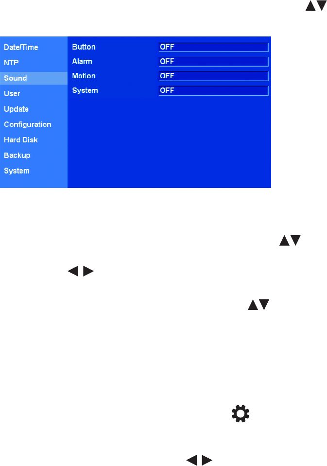
C2674M-C (7/09) 75
SOUND
The DX4500/DX4600 sound feature allows you to configure the DVR to issue an audible sound in response to the activation of a button, an event
(alarm or motion), and a system state. The sound feature has the following guidelines:
•Button: If set to ON, the system issues a single beep when a front panel or remote control button is pressed.
•Alarm: If set to ON, the system continues to beep approximately once per second until the alarm event is acknowledged.
•Motion: If set to ON, the system continues to beep approximately once per second until the alarm event is acknowledged.
•System: If set to ON, the system beeps when a system action occurs.
1. From the System menu, on the front panel or remote control, press ENTER. Then press the up/down arrow buttons to highlight
Sound. Using the mouse, click the Sound option. The Sound settings are displayed.
Figure 76. Sound Settings
2. Enable sound for any of the properties.
a. On the front panel or remote control, press ENTER twice, and then press the up/down arrow buttons to highlight a property.
Using the mouse, click the settings box of the desired property. The settings box changes color.
b. Press the left/right arrow buttons on the front panel or remote control to display ON. Using the mouse, click the settings box.
c. Do one of the following:
• On the front panel or remote control, press ENTER. Press the up/down arrow buttons to select another property, and
then press ENTER.
• Using the mouse, click another property.
The setting box changes color.
d. Repeat steps 2b and 2c to enable sound for the remaining properties.
3. Save the changes.
a. Do one of the following:
• On the front panel, press the MENU/ESC button or press the MENU/ESC button on the remote control until the
“Configuration data is changed. Save the new settings message?” dialog box is displayed.
• Using the mouse, click Exit. The Configuration data is changed. Save the new settings? dialog box is displayed.
b. On the front panel or remote control, press the left/right arrow buttons to highlight OK, and then press ENTER. Using the
mouse, click OK. The changes are saved and the Live View mode is displayed.

76 C2674M-C (7/09)
USER ACCOUNTS
User accounts are administered locally on the server or remotely over the network using the client application. A user account consists of three
items:
•ID: The user name is created by the system administrator. The default is ADMINISTRATOR ID.
The user name has the following guidelines:
–Characters: A to Z, a to z, numerals 0 to 9, and special characters.
–Name length: Up to 23 characters.
•Level: The three user levels are administrator, power, and normal; the user is assigned a level when the account is created. Table D
describes the user levels and permissions granted to each level.
•Password: Login user password created by the system administrator. The default administrator password is 000000, but it can be changed.
The password has the following guidelines:
–Characters: A to Z, a to z, numerals 0 to 9, and special characters.
–Password length: Must be between 4 to 8 characters long.
The DX4500/DX4600 supports 10 user accounts including the default administrator account.
Table D. User Levels and Permissions
DVR Operation User Level
Administrator Power Normal
Live View Yes Yes Yes
Search Yes Yes No
PTZ Yes Yes Yes
Alarm Off Yes Yes Yes
Instant Playback Yes Yes Yes
Instant Record Yes Yes Yes
Instant Backup Yes Yes No
Select Display Mode Yes Yes Yes
View System Log Yes Yes Yes
View System Information Yes Yes Yes
Setup Yes No No
Export Yes Yes No
Shut Down Yes No No
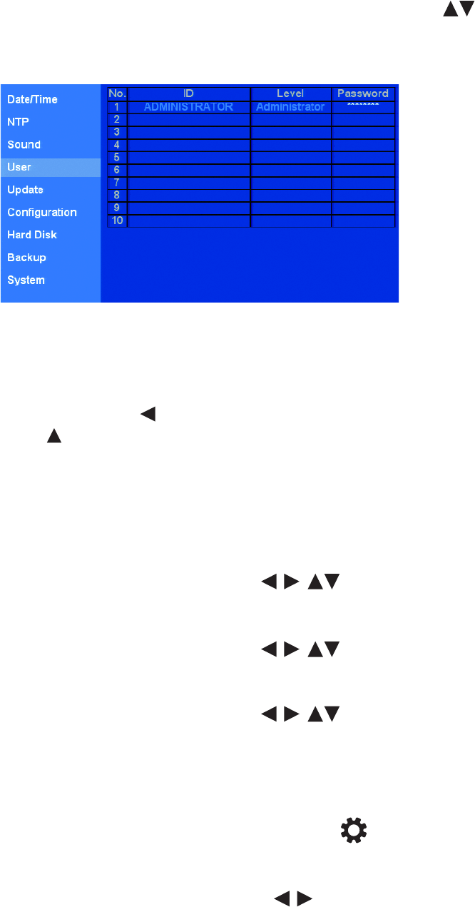
C2674M-C (7/09) 77
CHANGING THE ADMINISTRATOR DEFAULT PASSWORD
1. From the System menu, on the front panel or remote control, press ENTER. Then press the up/down arrow buttons to highlight User.
Using the mouse, click the User option. The User settings are displayed. By default, the DVR comes preconfigured with the user name set to
ADMINISTRATOR. The default password is 000000. As shown in Figure 77, the first user ID and level are unavailable. The password is
available and can be changed.
Figure 77. User Account Settings
2. To change the administrator password, do one of the following:
• On the front panel or remote control:
(1) Press ENTER. The cursor moves to row 2 of the ID column.
(2) In row 2, press the left arrow button to move the cursor immediately to the Password column settings box. Then press the
up arrow button to move the cursor to the ADMINISTRATOR password settings box. The settings box is highlighted.
(3) Press ENTER.
• Using the mouse, click the ADMINISTRATOR password settings box.
The “Please enter the current password” virtual keyboard is displayed. The cursor highlights 0 (zero).
3. Enter the current password (ADMINISTRATOR).
a. On the front panel or remote control, press ENTER. Using the mouse, click 0 (zero) six times.
b. On the front panel or remote control, press any of the arrow buttons to highlight OK and press ENTER. Using the
mouse, click OK. The “Enter the new password” virtual keyboard opens.
4. Enter the new password.
a. On the front panel or remote control, press any of the arrow buttons to move the cursor to a character and press
ENTER. Using the mouse, click a character. An asterisk is displayed in the text entry box for each character entered.
(1) Repeat step 4a to enter the remaining password characters.
b. On the front panel or remote control, press any of the arrow buttons to highlight OK and press ENTER. Using the
mouse, click OK. The “Confirm password” dialog box opens, prompting you to confirm the new password.
c. Repeat steps 4a and 4b to re-enter the password. Asterisks are displayed in the password settings box.
5. Save the changes.
a. Do one of the following:
• On the front panel, press the MENU/ESC button or press the MENU/ESC button on the remote control until the
“Configuration data is changed. Save the new settings message?” dialog box is displayed.
• Using the mouse, click Exit. The “Configuration data is changed. Save the new settings?” dialog box is displayed.
b. On the front panel or remote control, press the left/right arrow buttons to highlight OK and press ENTER. Using the mouse,
click OK. The changes are saved and the Live View mode is displayed.

78 C2674M-C (7/09)
ADDING A NEW USER
Up to nine additional users can be added to the user list. Only a user with administrator level permissions can add, modify, or delete users. For
information about user level permissions, refer to User Accounts on page 76.
1. From the System menu, on the front panel or remote control, press ENTER. Then press the up/down arrow buttons to highlight User.
Using the mouse, click the User option. The User settings are displayed.
2. Create a new user name.
a. Do one of the following:
• On the front panel or remote control, press ENTER. Press the up/down arrow buttons to select an empty roll, and then
press ENTER again.
• Using the mouse, click the ID settings box.
The “Enter the user name” virtual keyboard opens.
b. On the front panel or remote control, use any of the arrow buttons to enter the user name, and then press ENTER.
Using the mouse, click the characters.
c. On the front panel or remote control, press any of the arrow buttons to highlight OK, and then press ENTER. Using
the mouse, click OK. The user name is displayed in the ID column settings box.
3. Assign the permission level.
a. On the front panel or remote control, use any of the arrow buttons to move to the Level column setting box, and
then press ENTER. Using the mouse, left-click the Level column setting box. The settings box changes color.
b. On the front panel or remote control, press the left/right arrow buttons to select a permission level. Using the mouse, right-
or left-click the box to choose a level.
c. On the front panel or remote control, press the ENTER button. Using the mouse, click the Level setting box. The Level settings box
changes color.
4. Assign a password.
a. On the front panel or remote control, use any of the arrow buttons to move the cursor to the Password settings box,
and then press ENTER. Using the mouse, click the Password settings box.
The “Enter the new password” virtual keyboard is displayed. The cursor highlights 0 (zero).
5. Enter the new password.
a. On the front panel or remote control, press any of the arrow buttons to move the cursor to a character, and then
press ENTER. Using the mouse, click a character. An asterisk is displayed in the text entry box for each character entered.
b. Repeat step 4a to enter the remaining password characters.
c. On the front panel or remote control, press any of the arrow buttons to highlight OK, and then press ENTER. Using
the mouse, click OK. The “Confirm password” dialog box opens, prompting you to confirm the new password.
d. Repeat steps 4a and 4b to re-enter the password.
6. Save the changes.
a. Do one of the following:
• On the front panel, press the MENU/ESC button or press the MENU/ESC button on the remote control until the
“Configuration data is changed. Save the new settings message?” dialog box is displayed.
• Using the mouse, click Exit. The “Configuration data is changed. Save the new settings?” dialog box is displayed.
b. On the front panel or remote control, press the left/right arrow buttons to highlight OK, and then press ENTER. Using the
mouse click OK. The changes are saved and the Live View mode is displayed.
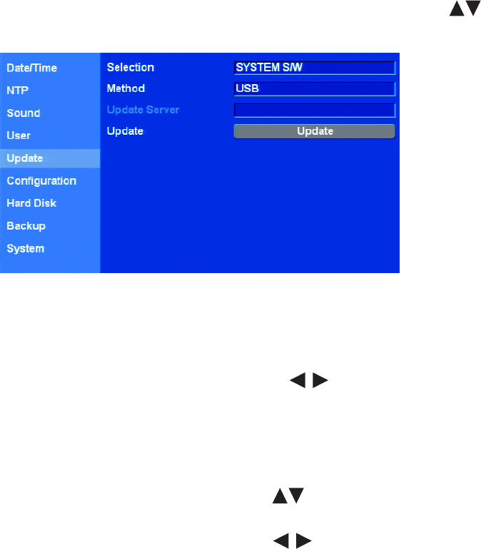
C2674M-C (7/09) 79
SOFTWARE UPDATE
The DX4500/DX4600 Update feature allows you to upgrade DVR software and add or upgrade PTZ protocols. The current DVR settings are not
deleted or replaced during the update process.
You can perform an update from either the USB drive or the network server.
• USB drive:
– All USB devices, except the USB device containing the update file, must be disconnected before you can use the USB drive.
– Format the USB drive using the DVR erase media utility before start the update process.
– If the system cannot find a valid update file, the “Cannot find valid update file.” message is displayed. In this case, ensure that there
are valid update files placed in the root directory of the USB drive and repeat the procedure.
NOTE: The upgrade file must be placed in the USB drive's root directory.
– If the system finds a valid update file, the “S/W update is in progress.” message is displayed.
• Network server:
– The DVR network settings must be configured. You must know the update server’s IP address to configure the settings.
– If the update server IP address is not configured, the “Change update server to Update Server for all entries.” message is displayed.
– If the incorrect update server IP address is configured or the system cannot located the update server, the “Update Server access failed”
message is displayed.
– If the system finds a valid update server and file, the “S/W update is in progress.” message is displayed.
1. From the System menu, on the front panel or remote control, press ENTER. Then press the up/down arrow buttons to highlight
Update. Using the mouse, click the Update option. The Update settings are displayed.
Figure 78. Update Settings
2. Update system software or PTZ protocols.
a. On the front panel or remote control, press ENTER twice. Using the mouse, click the Selection settings box. The settings box changes
color.
b. On the front panel or the remote control, press the left/right arrow buttons to display the desired settings. Using the mouse,
click the Selection settings box.
c. On the front panel or remote control, press ENTER. Using the mouse, click Selection. The settings box changes color.
3. Select the USB update method.
a. Connect or insert the USB device.
b. On the front panel or remote control, press the up/down arrow buttons to highlight Method, and then press ENTER. Using the
mouse, click the Method settings box. The settings box changes color.
c. On the front panel or remote control, press the left/right arrow buttons to display USB. Using the mouse, click the Selection
settings box.
d. On the front panel or remote control, press ENTER. Using the mouse, click Method. The settings box changes color.
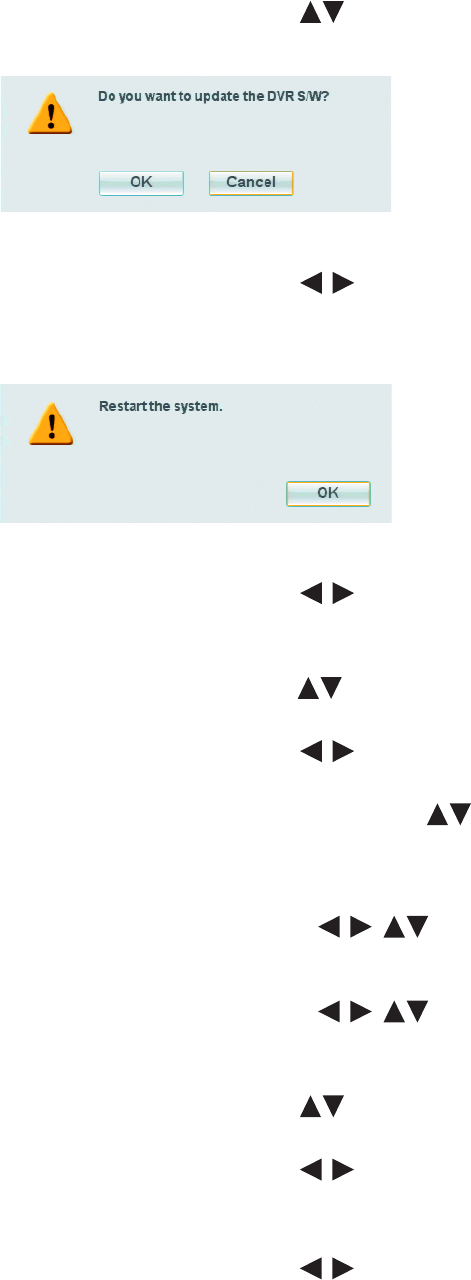
80 C2674M-C (7/09)
e. On the front panel or remote control, press the up/down arrow buttons to highlight Update, and then press ENTER. Using the
mouse, click Update. The “Do you want to update the DVR S/W?” dialog box opens.
Figure 79. DVR S/W Dialog Box
f. On the front panel or remote control, press the left/right arrow buttons to highlight OK, and then press ENTER. Using the
mouse, click OK. The system searches the media for the update file and starts the update process.
After the update process is complete, the “Restart the System” dialog box is displayed.
Figure 80. Restart the System Dialog Box
g. On the front panel or remote control, press the left/right arrow buttons to highlight OK, and then press ENTER. Using the
mouse, click OK. The system restarts.
4. Select the Network update method.
a. On the front panel or remote control, press the up/down arrow buttons to highlight Method, and then press ENTER. Using the
mouse, click the Method settings box. The settings box changes color.
b. On the front panel or remote control, press the left/right arrow buttons on the front panel or remote control to display
NETWORK. Using the mouse, click the Selection settings box.
c. On the front panel or remote control, press ENTER. Then press the up/down arrow buttons to highlight Update Server. Using
the mouse, click Update Server. The settings box changes color and the Update Server property is highlighted.
d. On the front panel or remote control, press ENTER. Using the mouse, click the Update Server settings box. The “Enter the Update
Server IP Address.” dialog box is displayed.
(1) On the front panel or remote control, press any of the arrow buttons to highlight the first character of the
update server IP address, and then press ENTER. Repeat this process to enter the remaining characters. Using the mouse, click
each character.
(2) On the front panel or remote control, press any of the arrow buttons to highlight OK, and then press ENTER.
Using the mouse, click OK. The IP address is displayed in the settings box.
5. Start the update process.
a. On the front panel or remote control, press the up/down arrow buttons to highlight Update, and then press ENTER. Using the
mouse, click Update. The “Do you want to update the DVR S/W?” dialog box opens.
b. On the front panel or remote control, press the left/right arrow buttons on the front panel or remote control to highlight OK,
and then press ENTER. Using the mouse, click OK. The system searches the media for the update file and starts the update process.
After the update process is complete, the “Restart the System” dialog box is displayed.
c. On the front panel or remote control, press the left/right arrow buttons on the front panel or remote control to highlight OK,
and then press ENTER. Using the mouse, click OK. The system restarts.
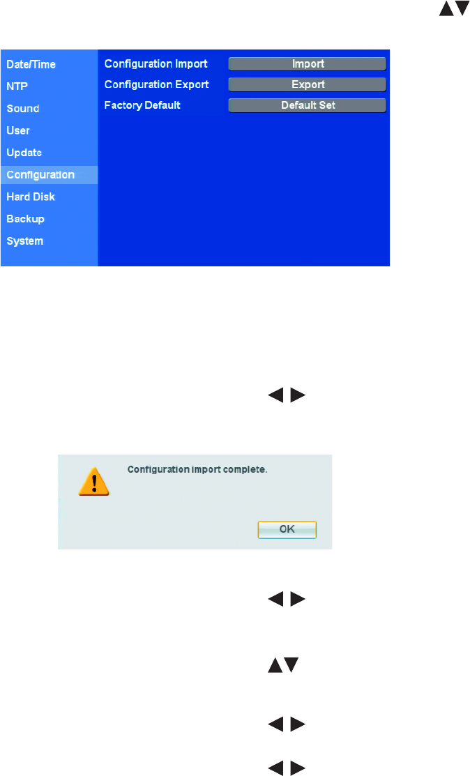
C2674M-C (7/09) 81
CONFIGURATION
IMPORTING, EXPORT, AND FACTORY DEFAULT SETTINGS
The DX4500/DX4600 Configuration option allows you to import and export the DVR configuration settings. Multiple DVRs can be configured
quickly from a USB drive. Factory defaults can be easily restored. For information about the factory default settings, refer to DX4500/DX4600
Factory Defaults on page 127.
1. From the System menu, on the front panel or remote control, press ENTER. Then press the up/down arrow buttons to highlight
Configuration. Using the mouse, click the Configuration option. The Configuration settings are displayed.
Figure 81. Configuration Settings
2. To import configuration settings:
a. Insert the USB device.
b. On the front panel or remote control, press ENTER twice. Using the mouse, click the Selection settings box. The “Would You Like to
Import the Configuration?” dialog box opens.
c. On the front panel or remote control, press the left/right arrow buttons to highlight OK, and then press ENTER. Using the
mouse, click OK. The import process starts. After the import process is complete, the “Configuration Import Complete” dialog box
opens.
Figure 82. Configuration Import Complete Dialog Box
d. On the front panel or remote control, press the left/right arrow buttons to highlight OK, and then press ENTER. Using the
mouse, click OK.
3. To export the DVR configuration settings:
a. On the front panel or remote control, press the up/down arrow buttons to highlight Configuration Export, and then press
ENTER. Using the mouse, click the Configuration Export settings box. The “Would You Like to Export the Configuration?” dialog box.
opens.
b. On the front panel or remote control, press the left/right arrow buttons to highlight OK, and then press ENTER. Using the
mouse, click OK. After export process is finished, the Configuration Export Complete dialog box opens.
c. On the front panel or remote control, press the left/right arrow buttons to highlight OK, and then press ENTER. Using the
mouse, click OK.
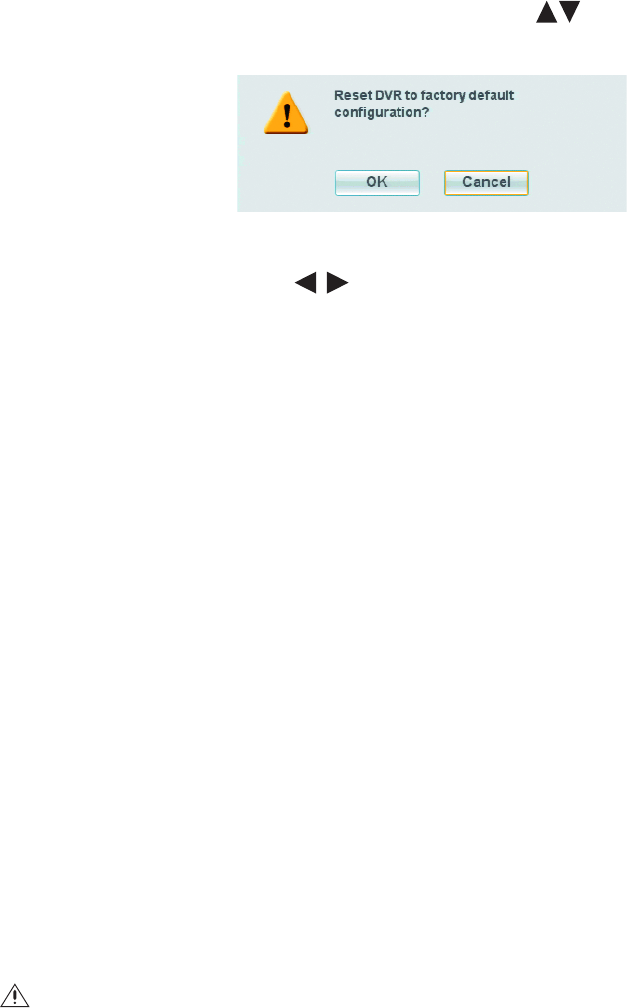
82 C2674M-C (7/09)
4. To reset the DVR to factory defaults:
NOTE: Setting the DVR to factory defaults deletes the customized settings. To save the customized settings, be sure to perform a
configuration export before resetting the DVR to the factory defaults.
a. On the front panel or remote control, press the up/down arrow buttons to highlight Factory Defaults, and then press ENTER.
Using the mouse, click the Configuration Export settings box. The “Reset DVR to factory default configuration?” dialog box opens.
Figure 83. Reset DVR Dialog Box
b. Press the left/right arrow buttons on the front panel or remote control to highlight OK, and then press ENTER. Using the
mouse, click OK. The DVR configuration is reset to factory defaults.
HARD DISK
The DX4500/DX4600 allows you to configure how the system administers hard disk storage.
The DVR combines the storage space of multiple HDDs into one large disk and creates two partitions: TEMP and DATA. The system allocates
6 GB of disk space to the TEMP partition; the remaining space is allocated to the DATA partition. When the HDDs are formatted, the system
creates two folders (Normal and Event) based on the Event Partition settings. A percentage of space is allocated to the Event folder (the default
setting is 50 percent); the remaining storage capacity is allocated to the Normal folder.
If the Event Partition setting is changed, the system forces a reformatting of all drives and re-allocates the space to the Normal and Event folder
based on the new event partition percentage.
NOTE: The terms normal partition and event partition are used when referencing the normal folder and the event folder.
•Format: Initializes all installed HDDs. The System Information dialog box lists the installed drives and their respective capacities. If a drive
is installed, the system prompts you to format the drive and all data on the drive(s) is erased.
• Overwrite:
–ALL: When the normal and event partitions are full, the system will begin overwriting. The oldest recorded data is overwritten first.
The default setting is ALL.
–NORMAL PARTITION: When the normal partition is full, the system will begin overwriting only the normal partition. The oldest
recorded data is overwritten first.
–EVENT PARTITION: When the event partition is full, the system will begin overwriting only the event partition. The oldest recorded
data is overwritten first.
–OFF: Blocks the overwriting of any partition.
•Full Warning: When the HDD has reached the configured percentage capacity, the system displays a warning message. The default
setting is OFF.
•Event Partition (size): Specifies the percentage of the total hard disk space allocated for storing event-related recorded video.
The remaining disk space is allocated for storing instant recorded video and continuous recorded video.
•Auto Delete: Allows you to configure when the DVR automatically deletes all data from the HDDs (OFF, 1 DAY, 2 DAYS, 5 DAYS,
10 DAYS, 20 DAYS, 30 DAYS, 40 DAYS, 50 DAYS, 60 DAYS). The default setting is OFF.
WARNING: If you change the event partition setting, the system will reformat all of the hard drives. All recorded video will be erased.
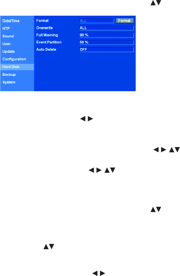
C2674M-C (7/09) 83
FORMATTING THE SYSTEM DRIVES
NOTE: The default setting is ALL. The settings box can be accessed, but it cannot be changed. If a new drive is installed, the system only
formats the newly installed drive; the current drives are not reformatted.
1. From the System menu, on the front panel or remote control, press ENTER. Then press the up/down arrow buttons to highlight Hard
Disk. Using the mouse, click the Hard Disk option. The hard drive settings are displayed.
Figure 84. Hard Disk Settings
2. Format all hard drives.
• On the front panel or remote control:
(1) Press ENTER, and then press the left/right arrow buttons to highlight the Format button.
(2) Press ENTER.
• Using the mouse, click the Format button.
The “Formatting the HDD will delete all existing data.” virtual keyboard opens.
a. Type yes to start the formatting process. On the front panel or remote control, press any of the arrow buttons to
highlight the first character of the word, and then press ENTER. Repeat this process to enter the remaining characters. Using the
mouse, click each character.
b. On the front panel or remote control, press any of the arrow buttons to highlight OK, and then press ENTER. Using
the mouse, click OK. After the hard drives are formatted, the “Restart the system.” dialog box is displayed.
c. On the front panel or remote control, press ENTER. Using the mouse, click OK. The system restarts.
WORKING WITH HARD DRIVES
1. From the System menu, on the front panel or remote control, press ENTER. Then press the up/down arrow buttons to highlight Hard
Disk. Using the mouse, click the Hard Disk option. The hard drive settings are displayed.
2. Configure the overwrite setting.
• On the front panel or remote control:
(1) Press ENTER. The format property is highlighted.
(2) Press the up/down arrow buttons to highlight Overwrite, and then press ENTER.
• Using the mouse, click the overwrite settings box.
The settings box changes color.
a. On the front panel or remote control, press the left/right arrow buttons to display the desired setting. Using the mouse, click
the settings box.
b. On the front panel or remote control, press ENTER. Using the mouse, click Overwrite. The settings box changes color.

84 C2674M-C (7/09)
3. Configure the full warning limit.
a. On the front panel or remote, press the up/down arrow buttons to highlight Full Warning, and then press ENTER. Using the
mouse, click the Full Warning settings box. The settings box changes color.
b. On the front panel or remote, press the left/right arrow buttons to display the desired setting. Using the mouse, click the
settings box.
c. On the front panel or remote control, press ENTER. Using the mouse, click Full Warning. The settings box changes color.
4. To configure the event partition size, repeat the procedure in step 3.
5. To configure the auto delete feature, repeat procedure in step 3.
BACKUP
The DX4500/DX4600 backup feature allows you to perform an instant backup of recorded data or configure the system to perform an automatic
backup of data on a scheduled basis. The administrator or power user has permissions for setting up and conducting backup procedures.
The DX4500/DX4600 backup feature allows you to schedule how the DVR backs up recorded video data.
•Partition Selection: Allows you to specify the type of data to be backed up: all (instant, normal, and event [alarm/motion]), normal
(instant and normal), or event (alarm and motion).
•Device: Indicates the destination backup media. The DVR determines what media is available and displays those media as options. If a
USB device is installed, the system displays the manufacturer’s name of the device. (for example, a ClipDrive or Flash Drive).Table E
describes the guidelines for backing up data to various media.
•Schedule: Specifies the backup period.
–OFF: Disables the backup feature.
–Daily: Schedules daily backups between the start and end time
–Weekly: Schedules weekly backups, allowing you to specify different start and end times for each day of the week.
–Instant: Allows you to manually backup data by specifying the date and the start and end time.
•Schedule Start: Specifies the day and time (in hours and minutes) the scheduled backup begins.
•Time Range Date: Defines the date the backup process begins.
•Time Range Start: Indicates the time the backup process begins.
•Time Range End: Indicates the time the backup process ends.
You cannot use the Estimate Size, Start Backup, or Erase Media options while the backup process is running.
The USB device should not be removed while the backup process is running. Doing so can disrupt the formatting of the USB drive. If the USB is
removed, it will have to be reformatted to work properly.
Table E. Guidelines for Backing Up to Media Devices
Guideline Media
CD±R CD±RW DVD±R DVD±RW USB
Media can be formatted. No Yes No Yes Yes
Media can be formatted on a PC using the FAT32 file system.
This media may or may not work in the DVR. Therefore, Pelco
recommends formatting the media on the DVR.
No Yes No Yes Yes
Media must be formatted on the DX4500/DX4600 before
backing up or exporting data to the device.
N/A Yes N/A Yes Yes
Device can be used for instant backup. Yes Yes Yes Yes Yes
Device can be used for daily or weekly backups. No No No No Yes
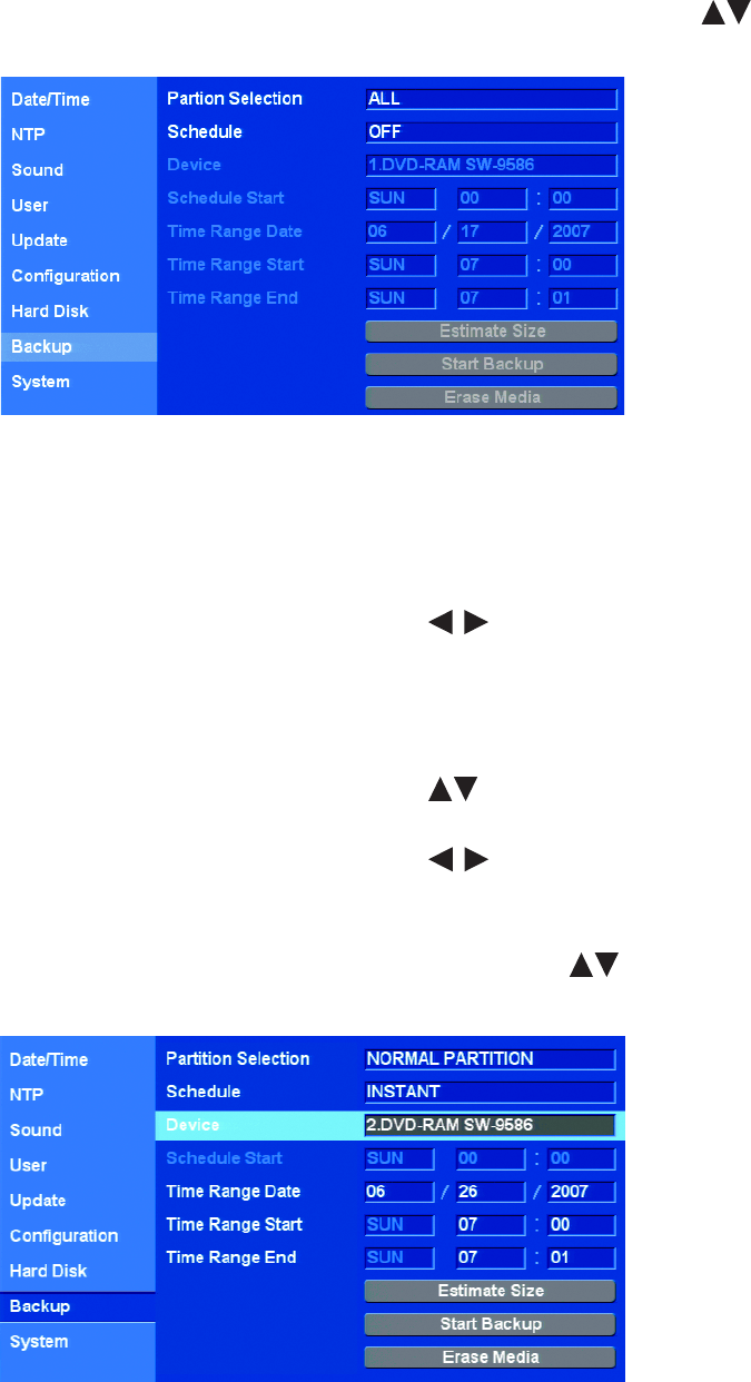
C2674M-C (7/09) 85
INSTANT BACKUP
1. From the System menu, on the front panel or remote control, press ENTER. Then press the up/down arrow buttons to highlight
Backup. Using the mouse, click the Backup option. The Backup settings are displayed.
Figure 85. Backup Settings
2. Connect or insert the backup media.
3. Select the partition.
a. On the front panel or remote control, press ENTER twice. Using the mouse, click the Partition Selection settings box. The settings box
changes color.
b. On the front panel or remote control, press the left/right arrow buttons on the front panel or on the remote control to select
a partition. Using the mouse, click the settings box.
c. On the front panel or remote control, press ENTER to select the setting. Using the mouse, click Partition Selection. The settings box
changes color.
4. Select the backup schedule.
a. On the front panel or remote control, press the up/down arrow buttons to highlight Schedule, and then press ENTER. Using
the mouse, click the settings box.
b. On the front panel or remote control, press the left/right arrow buttons to select the INSTANT backup schedule. Using the
mouse, click the schedule settings box.
5. Select a media.
a. On the front panel or remote control, press ENTER. Then press the up/down arrow buttons to move to Device. Using the
mouse, click Device.
Figure 86. Selecting the Backup Schedule
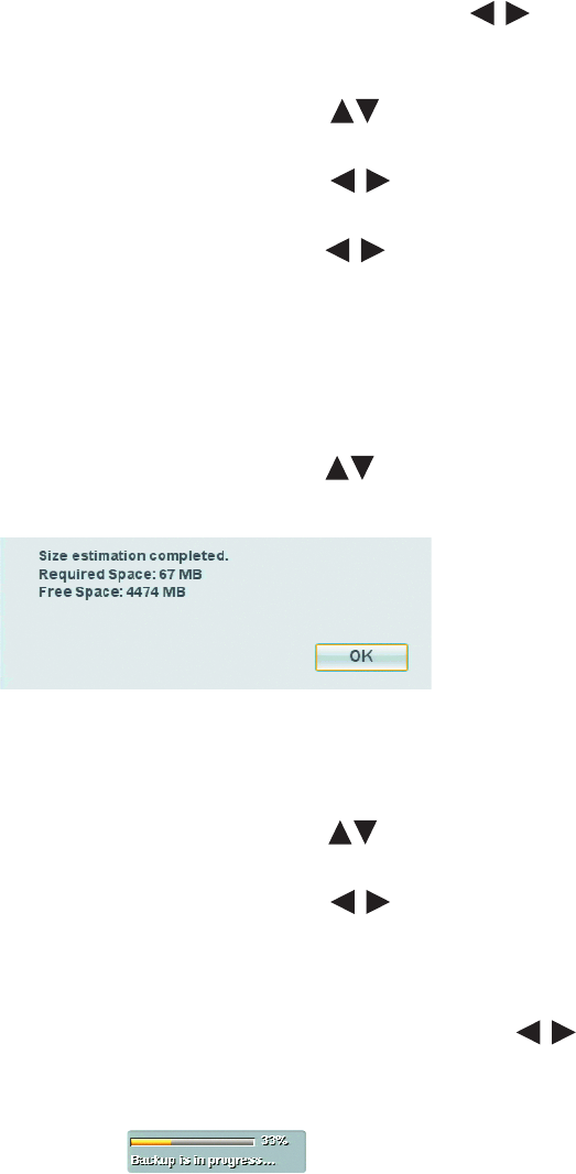
86 C2674M-C (7/09)
b. On the front panel or remote control, press ENTER. Then press the left/right arrow buttons to select a media. Using the
mouse, click the device settings box.
6. Select the time range date.
a. On the front panel or remote control, press the up/down arrow buttons to highlight Time Range Date, and then press ENTER.
Using the mouse, click a month settings box. The settings box changes color.
b. On the front panel or remote control, press the left/right arrow buttons to highlight a start date settings box: month, day, or
year, and then press ENTER. Using the mouse, click the settings box. The settings box changes color.
c. On the front panel or remote control, press the left/right arrow buttons to display the desired setting, and then press ENTER.
Using the mouse, right- or left-click the settings box. The settings box changes color.
d. If applicable, repeat steps 6b and 6c to select the remaining parts of the Time Range Start date.
7. Repeat the procedure in steps 6a through 6c to select the Time Range Start time.
8. Repeat the same procedure to select the Time Range End time. The Time Range End cannot be the same as the Time Range Start.
9. Verify the backup media has sufficient space.
a. On the front panel or remote control, press the up/down arrow buttons to highlight Estimate Size, and press ENTER. Using the
mouse, click Estimate Size. The system displays the size estimation dialog box.
Figure 87. Estimated Disk Storage
b. On the front panel or remote control press ENTER. Using the mouse, click OK.
10. Start the backup.
a. On the front panel or remote control, press the up/down arrow buttons to highlight Start Backup, and press ENTER. Using the
mouse, click Start Backup. The “Would you like to start backup dialog” box opens.
b. On the front panel or remote control, press the left/right arrow buttons to highlight OK, and then press ENTER. Using the
mouse, click OK. The backup process starts (no backup status information is displayed).
c. To view the backup status indicator, on the front panel or remote control, press MENU/ESC. Using the mouse, click Exit. If new
settings are made, the “Configuration data is changed.” dialog box is displayed. Otherwise, the system exits to the Live View mode.
d. If the “Configuration data is changed.” dialog box is displayed, press the left/right arrow buttons on the front panel or
remote control to highlight OK, and then press ENTER. Using the mouse, click OK. The system returns to the Live View mode.
The backup status indicator is displayed and two messages appear (refer to Figure 88).
Figure 88. Backup Status Indicators
After the backup process is complete, the system displays the “Backup completed.” dialog box.
e. On the front panel or remote control, press ENTER. Using the mouse, click OK.
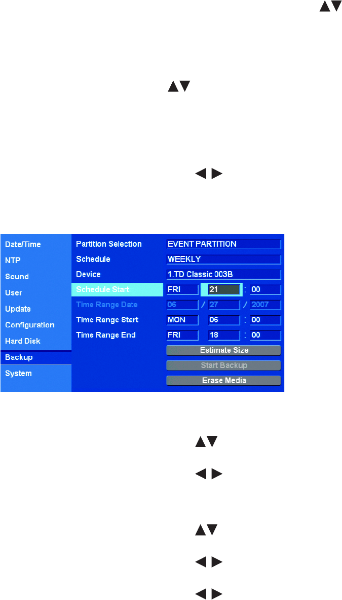
C2674M-C (7/09) 87
WEEKLY BACKUP SCHEDULE
The DX4500/DX4600 weekly backup feature allows you to perform an automatic backup of recorded data to a USB device; the DVR does not back
up data to CD/DVD media. Data can be backed up for one or more days, from one minute to 24 hours. And, the DVR can be configured to back up
all, normal (instant and normal recorded video), or event-initiated (alarm and motion) recorded video.
1. From the System menu, on the front panel or remote control, press ENTER. Then press the up/down arrow buttons to highlight the
Backup option. Using the mouse, click Backup. The Backup settings are displayed.
2. Connect or insert the backup media.
3. Highlight the schedule option.
• On the front panel or remote control:
(1) Press ENTER, and then press the up/down arrow buttons to highlight Schedule.
(2) Press ENTER.
• Using the mouse, click the schedule settings box.
The settings box changes color.
4. Select the schedule setting:
a. On the front panel or remote control, press the left/right arrow buttons to display WEEKLY. Using the mouse, click the
settings box.
b. On the front panel or remote control, press ENTER to select the setting. Using the mouse, click Schedule. The settings box changes
color.
Figure 89. Configuring a Weekly Backup Schedule
5. Select a media with sufficient capacity to store the backup data.
a. On the front panel or remote control, press the up/down arrow buttons to highlight Device, and then press ENTER. Using the
mouse, click Device settings box. The settings box changes color.
b. On the front panel or remote control, press the left/right arrow buttons to select a media, and then press ENTER. Using the
mouse, click the settings box.
6. Select the Schedule Start day and time. This setting configures the backup on a weekly basis, and specifies the day and time backup is
performed. This setting does not determine the length of the backup process.
a. On the front panel or remote control, press the up/down arrow buttons to highlight Schedule Start, and press ENTER. Using
the mouse, click the day settings box. The settings box changes color.
b. On the front panel or remote control, press the left/right arrow buttons to highlight the desired day, and then press ENTER.
Using the mouse, click the settings box. The settings box changes color.
c. On the front panel or remote control, press the left/right arrow buttons on the front panel or remote control to highlight the
hour settings box, and then press ENTER. Using the mouse, click the settings box. The settings box changes color.

88 C2674M-C (7/09)
d. On the front panel or remote control, press the left/right arrow buttons to highlight the desired hour, and then press ENTER.
Using the mouse, click the settings box.
e. Repeat the procedure in steps 6b and 6c to select the desired minutes.
7. Repeat the procedure in step 6 to select the Time Range Start day and time. This setting establishes the start day and time of the backup
procedure.
8. Repeat the procedure in step 6 to select the Time Range End day and time. This setting establishes the end day and time of the backup
procedure. The time range start and end days can be the same; however, the time range start and end times cannot be the same. The Time
Range End time must be at least one minute later than the Time Range Start time.
9. Verify the backup media has sufficient space.
a. On the front panel or remote control, press the up/down arrow buttons to highlight Estimate Size, and press ENTER. Using the
mouse, click Estimate Size. The system displays the estimated size dialog box.
b. On the front panel or remote control, press ENTER. Using the mouse, click OK.
10. Start the backup.
a. On the front panel or remote control, press the up/down arrow buttons to highlight Start Backup, and press ENTER. Using the
mouse, click Start Backup. The “Would you like to start backup” dialog box opens.
b. On the front panel or remote control, press the left/right arrow buttons to highlight OK, and then press ENTER. Using the
mouse, click OK. The backup process starts (no backup status information is displayed).
c. To view the backup status indicator, on the front panel or remote control, press MENU/ESC. Using the mouse, click Exit. If new
settings are made, the “Configuration data is changed.” dialog box is displayed. Otherwise, the system exits to the Live View mode.
d. If the “Configuration data is changed.” dialog box is displayed, press the left/right arrow buttons on the front panel or
remote control to highlight OK, and then press ENTER. Using the mouse, click OK. The system returns to the Live View mode.
The backup status indicator is displayed and two messages appear (refer to Figure 90).
Figure 90. Backup Status Indicators
After the backup process is complete, the system displays the “Backup completed.” dialog box.
e. On the front panel or remote control, press ENTER. Using the mouse, click OK.
DAILY BACKUP SCHEDULE
The DX4500/DX4600 daily backup feature allows you to perform a daily automatic backup of recorded data to a USB device; the DVR does not
back up data to CD/DVD media. You can configure the time when the backup process starts and ends. The start and end times can be specified,
and the DVR can be configured to backup all, normal (instant and normal recorded video), or event-initiated (alarm and motion) recorded video.
1. From the System menu, on the front panel or remote control, press ENTER. Then press the up/down arrow buttons to highlight the
Backup option. Using the mouse, click Backup. The Backup settings are displayed.
2. Connect or insert the backup media.
3. Highlight the schedule option.
• On the front panel or remote control:
(1) Press ENTER, and then press the up/down arrow buttons to highlight Schedule.
(2) Press ENTER.
• Using the mouse, click the Schedule settings box.
The settings box changes color.
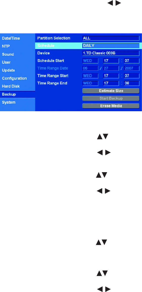
C2674M-C (7/09) 89
4. Select the Schedule setting:
a. On the front panel or on the remote control press the left/right arrow buttons to display DAILY. Using the mouse, click the
settings box.
b. On the front panel or on the remote control press ENTER to select the setting. Using the mouse, click Schedule. The settings box
changes color.
Figure 91. Configuring the Daily Backup Schedule
5. Select a media with sufficient capacity to store the backup data.
a. On the front panel or remote control, press the up/down arrow buttons to highlight Device, and then press ENTER. Using the
mouse, click Device settings box. The settings box changes color.
b. On the front panel or remote control, press the left/right arrow buttons to select a media, and then press ENTER. Using the
mouse, click the settings box.
6. Select the time range starting time.
a. On the front panel or remote control, press the up/down arrow buttons to highlight Time Range Start, and press ENTER. Using
the mouse, click the day settings box. The settings box changes color.
b. On the front panel or remote control, press the left/right arrow buttons to highlight the desired hour, and then press ENTER.
Using the mouse, click the settings box. The settings box changes color.
c. Repeat the procedure in steps 6b to select the desired minutes.
7. Repeat the procedure in step 6a to select the Time Range End day and time. The time range start and end day can be the same; however,
the time range start and end times cannot be the same. The Time Range End time must be at least one minute later than the Time Range
Start time.
8. Verify the backup media has sufficient space.
a. On the front panel or remote control, press the up/down arrow buttons to highlight Estimate Size, and press ENTER. Using the
mouse, click Estimate Size. The system displays the estimated size dialog box.
b. .On the front panel or remote control, press ENTER. Using the mouse, click OK.
9. Start the backup.
a. On the front panel or remote control, press the up/down arrow buttons to highlight Start Backup, and press ENTER. Using the
mouse, click Start Backup. The “Would you like to start backup” dialog box opens.
b. On the front panel or remote control, press the left/right arrow buttons to highlight OK, and then press ENTER. Using the
mouse, click OK. The backup process starts (no backup status information is displayed).
c. To view the backup status indicator, on the front panel or remote control, press MENU/ESC. Using the mouse, click Exit. If new
settings are made, the “Configuration data is changed.” dialog box is displayed. Otherwise, the system exits to the Live View mode.
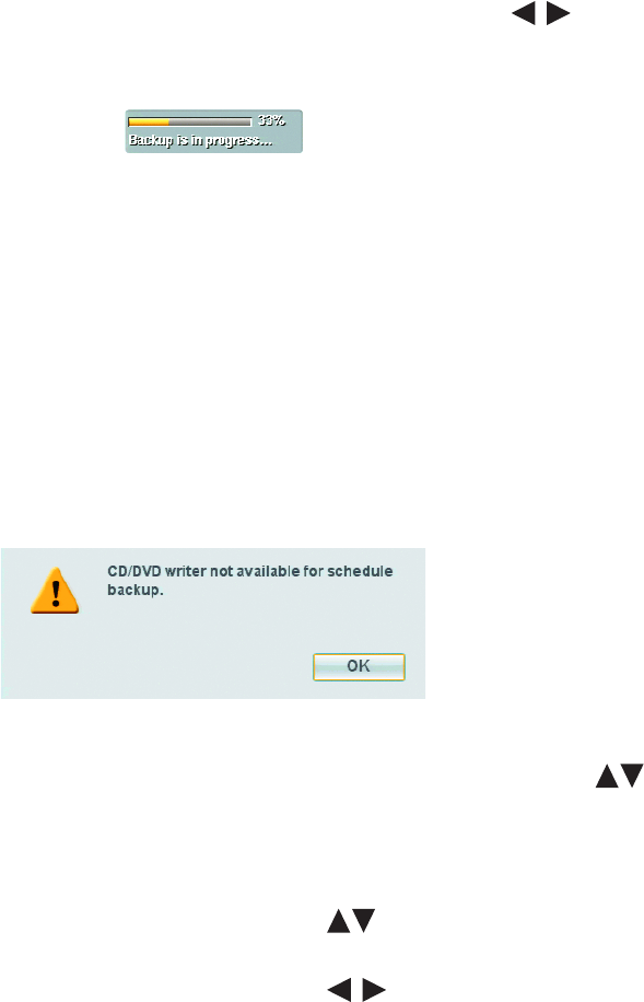
90 C2674M-C (7/09)
d. If the “Configuration data is changed.” dialog box is displayed, press the left/right arrow buttons on the front panel or
remote control to highlight OK, and then press ENTER. Using the mouse, click OK. The system returns to the Live View mode.
The backup status indicator is displayed and two messages appear (refer to Figure 92).
Figure 92. Backup Status Indicators
After the backup process is complete, the system displays the “Backup completed.” dialog box.
e. On the front panel or remote control, press ENTER. Using the mouse, click OK.
ERASING AND FORMATTING MEDIA
The DX4500/DX4600 erase and format features allow you to format media for use with the DVR. Although media can be formatted on a PC, Pelco
recommends that it be formatted on the DVR to guarantee functionality.
NOTE: Media not formatted with the DX4500/DX4600 may not work.
For information about media used with the DX4500/DX4600, refer to Table E on page 84. If the schedule option setting is weekly or daily, the
erase/format process stops and the “CD/DVD writer not available for schedule backup.” dialog box is displayed.
Figure 93. CD/DVD Writer Not Available Dialog Box
1. From the System menu, on the front panel or remote control, press ENTER. Then press the up/down arrow buttons to highlight the
Backup option. Using the mouse, click Backup. The Backup settings are displayed.
2. Connect or insert the backup media.
3. Select the schedule setting.
a. On the front panel or remote control, press the up/down arrow buttons to highlight Schedule, and then press ENTER. Using
the mouse, click the settings box. The settings box changes color.
b. On the front panel or remote control, press the left/right arrow buttons to display a schedule. Using the mouse, click the
settings box. The setting OFF disables the erase media function.
c. On the front panel or remote control, press ENTER to select the setting. Using the mouse, click Schedule. The settings box changes
color.
4. Repeat the procedure in step 2 to select the desired device.
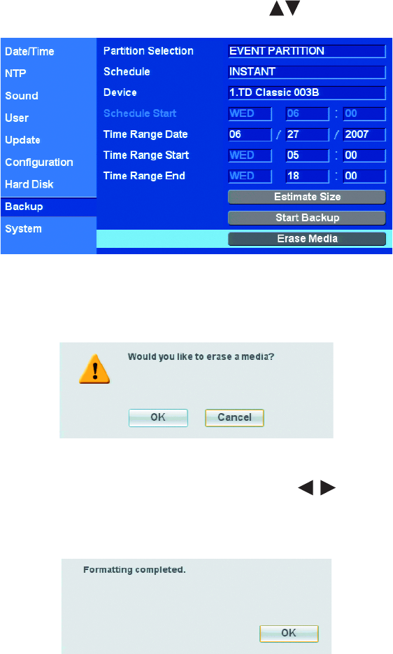
C2674M-C (7/09) 91
5. Start the formatting process.
a. On the front panel or remote control, press the up/down arrow buttons to highlight Erase Media.
Figure 94. Starting the Formatting Process
b. On the front panel or remote control, press ENTER. Using the mouse, click Erase Media. The “Would you like to erase a media?”
dialog box opens.
Figure 95. Would You Like to Erase a Media Dialog Box
c. On the front panel or on the remote control press the left/right arrow buttons to highlight OK, and then press ENTER. Using
the mouse, click OK. The “Media formatting is in progress” dialog box is displayed.
After the media is formatted, the system displays the “Formatting completed.” dialog box.
Figure 96. Formatting Completed Dialog Box
d. On the front panel or remote control, press ENTER. Using the mouse, click OK.
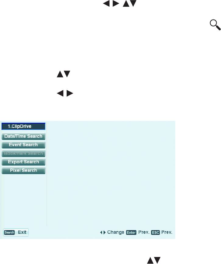
92 C2674M-C (7/09)
VIEWING BACKED UP VIDEO
The DX4500/DX4600 supports three different search modes when viewing backed up video: date/time, event, and pixel search.
NOTE: Video that is backed up on the DX4500/DX4600 server can only be played back on the server.
1. On the front panel or remote control, press any of the arrow buttons to select a camera pane. Using the mouse, click a
camera pane. A red border highlights the selected pane.
2. To display the search window, on the front panel or remote control, press SEARCH. Using the mouse, click the Search icon .
By default, the cursor moves to the Date/Time Search option. The current month’s calendar is displayed.
3. The default internal HDD is the search media. Select the media on which to conduct a search of the backed up video.
• On the front panel or remote control, do the following:
(1) Press MENU/ESC. The Date/Time Search option is highlighted.
(2) Press the up/down arrow buttons to move to the media settings box, and then press ENTER. The media settings box
changes color.
(3) Press the left/right arrow buttons to display a backup media, and then press ENTER. The media settings box changes
color.
• Using the mouse, click INTERNAL HDD, and then click the settings box.
Figure 97. Selecting USB Backup Media
4. To conduct a search, on the front panel or remote control, press the up/down arrow buttons to move to the Date/Time Search, Event
Search, or Pixel Search option, and then press ENTER. Using the mouse, click the search option. The search screen for the selected option
displays.
5. Use the selected search option’s features to search the backed up video. For information about the search feature, refer to Searching for
Video Events on page 113.
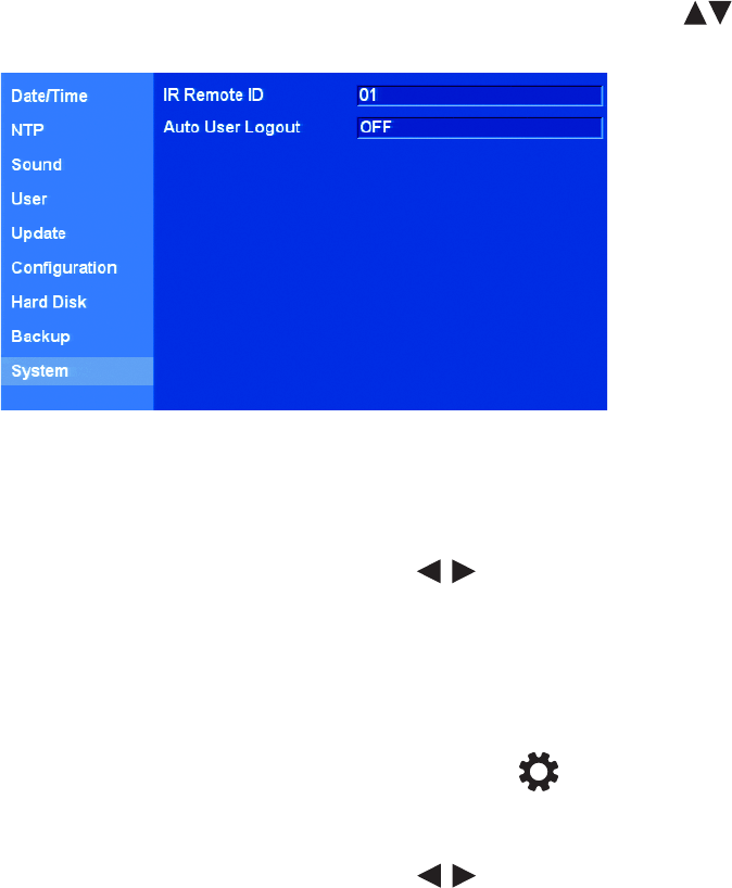
C2674M-C (7/09) 93
SYSTEM IR REMOTE ID AND USER LOGOUT
IR REMOTE ID
The DX4500/DX4600 infrared (IR) ID feature allows you to transmit a unique IR Remote ID (01–09) from the remote control to one or more DVRs.
Each DVR that is preconfigured with the transmitted ID is enabled to respond to and be operated by the remote control. All DVRs with a different
ID are disabled from responding to the remote control but are not disabled from normal operation.
NOTE: For proper operation and control, all IR receivers must be in the line of sight of the remote control (refer to the following examples).
• For example, you have two DVRs: Lobby and Front Entrance. Both are in the line of sight of the remote control. Lobby is preconfigured for IR
Remote ID 02 and Front Entrance is preconfigured for ID 03.
– If the remote control transmits ID 02, Lobby is enabled to respond to the remote control and Front Entrance is disabled from responding.
– If the remote control transmits ID 03 to both DVRs, Front Entrance is enabled to respond to the remote control and Lobby is disabled
from responding.
• For example, Front Entrance (which was previously enabled) is not in the line of sight of the remote control but Lobby is in its line of sight.
The remote control transmits ID 02.
– Front Entrance remains enabled because it did not receive the IR transmission. It continues to respond to remote control commands
intended for Lobby.
– Lobby is enabled and responds to the remote control.
1. From the System menu, on the front panel or remote control, press ENTER. Then press the up/down arrow buttons to highlight the
System option. Using the mouse, click System. The system settings are displayed.
Figure 98. System Settings
2. On the front panel or remote control, press ENTER twice. Using the mouse, click the IR Remote ID settings box. The settings box changes
color.
3. Change the DVR IR remote ID.
a. On the front panel or remote control, press the left/right arrow buttons to display the desired ID. Using the mouse, click the
settings box.
b. On the front panel or remote control, press ENTER to select the setting. Using the mouse, click IR Remote ID. The settings box
changes color.
4. Save the changes.
a. Do one of the following:
• On the front panel, press the MENU/ESC button or press the MENU/ESC button on the remote control until the
“Configuration data is changed. Save the new settings message?” dialog box is displayed.
• Using the mouse, click Exit. The “Configuration data is changed. Save the new settings?” dialog box is displayed.
b. On the front panel or remote control, press the left/right arrow buttons to highlight OK, and then press ENTER. Using the
mouse, click OK. The changes are saved and the Live View mode is displayed.
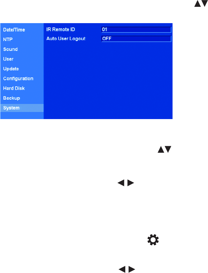
94 C2674M-C (7/09)
5. To transmit an IR Remote ID from the remote control to the DVRs, ensure that the units are in the line of sight of the remote control and do
the following:
NOTE: This step requires a quick response when programming the remote control.
a. On the remote control, press the ID button. Within two seconds, press a number representing the DVR’s IR remote ID. The system
beeps.
b. To verify the remote control is communicating with the selected DVR, press MENU/ESC. The Setup window is displayed.
AUTO USER LOGOUT
You can configure the DX4500/DX4600 to automatically log off users.
1. From the System menu, on the front panel or remote control, press ENTER. Then press the up/down arrow buttons to highlight the
System option. Using the mouse, click System. The System settings are displayed.
Figure 99. System Settings
2. To select the Auto User Logout setting.
• On the front panel or remote control, press ENTER. Then press the up/down arrow buttons to highlight Auto User Logout and
press ENTER.
• Using the mouse, click the Auto User Logout settings box.
The settings box changes color.
a. On the front panel or remote control, press the left/right arrow buttons to display the desired setting. Using the mouse, click
the settings box.
b. On the front panel or remote control, press ENTER to select the setting. Using the mouse, click Auto User Logout. The settings box
changes color.
3. Save the changes.
a. Do one of the following:
• On the front panel, press the MENU/ESC button or press the MENU/ESC button on the remote control until the
“Configuration data is changed. Save the new settings message?” dialog box is displayed.
• Using the mouse, click Exit. The “Configuration data is changed. Save the new settings?” dialog box is displayed.
b. On the front panel or remote control, press the left/right arrow buttons to highlight OK, and then press ENTER. Using the
mouse, click OK. The changes are saved and the Live View mode is displayed.

C2674M-C (7/09) 95
Recovering the Administrator Password
To recover the administrator user password, do the following:
1. On the left side of the unit, locate the manufacturer’s serial number.
2. Contact Pelco Product Support with the following information:
a. Manufacturer’s serial number.
b. Current date located on the toolbar.
c. Any additional information requested by Pelco Product Support.
3. To enter the password provided by Pelco Product Support:
a. On the toolbar, click the Login icon . The Login virtual keyboard opens.
b. Enter the password.
c. Click OK.
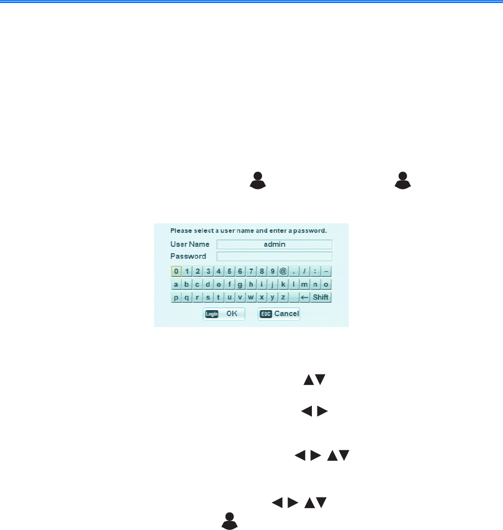
96 C2674M-C (7/09)
Operation
About Basic System Defaults
The DX4500/DX4600 comes preconfigured with system defaults that allow the DVR to be used to immediately view and record video. For a
description of all of the system defaults, refer to DX4500/DX4600 Factory Defaults on page 127.
Live Video
After the DX4500/DX4600 is installed and cameras are attached, the DVR starts and immediately begins displaying live video; the DVR is also
configured to record video immediately after starting. By default, the recording mode is configured for alarm and motion recording.
Log on to the system.
1. On the front panel or remote control, press the Login button . Using the mouse, click the Login icon . The virtual keyboard is
displayed. The default user name is admin. The cursor highlights the first character on the virtual keyboard.
Figure 100. Login Virtual Keyboard
2. Select your user name.
a. On the front panel or remote control, press the up/down arrow buttons to highlight the user name settings box. Using the
mouse, click the User Name settings box.
b. On the front panel or remote control, press the left/right arrow buttons to display your user name. Using the mouse, click the
settings box.
3. Enter your password.
• On the front panel or remote control, press any of the arrow buttons to select the first character of your password,
and then press ENTER. Repeat this process to select the remaining characters.
• Using the mouse, click each character of the password.
4. On the front panel or remote control, press any of the arrow buttons to select OK, and then press ENTER. Using the mouse,
click OK. The system logs you on and the Login icon changes color, indicating that you have successfully logged on to the DVR.

C2674M-C (7/09) 97
INSTANT RECORD AND PLAYBACK
The instant record feature allows you to start a manual recording session immediately from the live view mode. Initiate the instant record mode
for channels that are scheduled for normal, alarm, or motion record mode. Instant record is the highest priority recording event.
Observe the following instant record conditions:
• Instant (or normal) recording cannot start if the following conditions exist:
– Video loss is displayed for the channel.
– Overwrite is set to OFF and the hard disk normal partition storage space is full.
– The normal record mode is not available. If the event partition is set to 100 percent, the normal record mode is disabled because hard
disk space for storing normal record video is not available.
• The partition (folder) used by each recording mode:
–Normal partition: Video recorded in the instant and normal record mode is stored in the normal folder. If the normal folder is set to
0 (zero) percent (the event partition is 100 percent), the DVR will not operate in the instant or normal record mode.
–Event partition: Video recorded in the alarm and motion record mode is stored in the event partition. If the event partition is set to
0 (zero) percent, the DVR will not operate in the alarm or motion record mode.
For information about how hard drive storage is organized, refer to Playback Video on page 111.
• Instant, normal, alarm, and motion recording mode priority.
The instant playback feature allows you to simultaneously play back video and record live video.
STARTING AND STOPPING INSTANT RECORD
1. On the front panel or remote control, press REC and the channel number. Using the mouse, click the camera’s recording indicator .
The recording indicator immediately changes to the Instant Record indicator .
2. To stop instant record, on the front panel or remote control, press REC and the channel number. Using the mouse, click the Instant Record
indicator The recording indicator immediately changes to the scheduled recording mode.
INSTANT PLAYBACK
The DX4500/DX4600 supports two playback modes, instant playback and playback. Instant playback is accessed from the live view mode and
allows you to simultaneously play back and record video from the selected channel. Playback is displayed in picture-in-picture (PIP) presentation
in a separate pane. For information about the playback mode, refer to Playback Video on page 111.
Instant playback mode contains the following features:
•Playback: Video is only played back for one channel at a time, starting in the forward direction.
•Playback controls: All controls are available.
•Timing: Playback can be configured to begin two minutes prior to the start of an event.
Instant playback has the following conditions:
• Played back video is viewed separately from the live video being recorded. Use the zoom controls to adjust the size of the playback video
view pane (1x, 4x, and full size).
• The playback pane can be moved to another location in the application window.
1. On the front panel or remote control, press any of the arrow buttons to select a camera pane. Using the mouse, click a
camera pane. A red border highlights the selected pane.
2. To initiate instant playback, on the front panel or remote control, press the play button . Using the mouse, click the play button .
The DVR displays playback video.
3. To view the playback video and live video simultaneously, on the front panel or remote control, press any of the arrow buttons
to move the pane. Using the mouse, left-click and drag the pane.
The PIP pane relocates, and you can view playback and live video simultaneously.
N
I
I
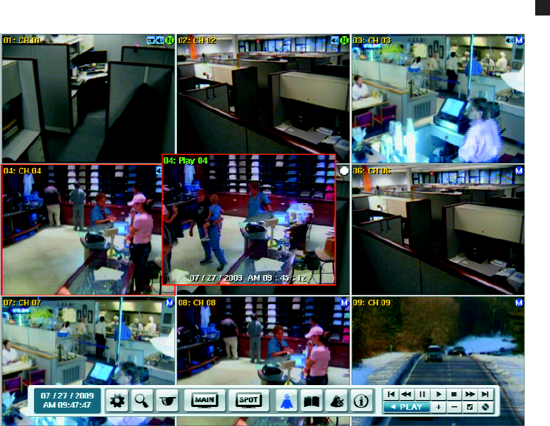
98 C2674M-C (7/09)
4. To return to the live view mode, on the front panel or remote control, press STOP. Using the mouse, click the stop button .
Figure 101. Viewing Playback and Live Video Simultaneously
PTZ IN LIVE VIEW
The DX4500/DX4600 displays a PTZ control for operating and administering cameras that support PTZ functions using Pelco C, Pelco P, and D
protocols. PTZ control is also available for supported third-party dome cameras. The PTZ option must be configured for each camera channel.
•Programming: To program or clear presets, preset tours, and patterns, the SET icon must be engaged. While in PTZ programming mode,
multiple presets can be programmed.
•Activating a PTZ feature: To activate presets, tours, and patterns, the SET icon must be disengaged. The PTZ option must be configured
for each camera channel before the PTZ control is used to operate the camera. You must have administrator level permissions to configure
DX4500/DX4600 features. For information about setting up PTZ options, refer to PTZ Setup on page 29.
• The PTZ feature is available to administrator, power, and normal level users.
• No other DVR operation, other than those initiated using the PTZ control, is available when the PTZ control is displayed.
• If someone is controlling a PTZ camera using the DVR, you cannot use the PTZ function and vice versa.
• The DVR will not perform instant record when the PTZ control is displayed.
• The PTZ control has a drag and drop feature.
• The PTZ control opens in the last location in which it was used.
You can also use the Pelco KBD300A keyboard to configure and operate PTZ devices. For information about configuring PTZ features, refer to PTZ
Presets on page 101. For information about working with the KBD300A keyboard, to configure and operate PTZ devices, refer to Working With
PTZ Devices Using the KBD300A Keyboard on page 99. For information about the PTZ control and a description of its buttons, refer to PTZ
Control on page 15.

C2674M-C (7/09) 99
WORKING WITH PTZ DEVICES USING THE KBD300A KEYBOARD
You can use the Pelco KBD300A keyboard to setup and operate PTZ devices. Refer to Table F for a list of supported KBD300A controls. For
information about the DX4500/DX4600 GUI PTZ Control, refer to PTZ Control on page 15. For information about connecting and operating the
KBD300A, refer to the KBD300USBKIT Installation manual.
Table F. Supported KBD300A Keyboard Features
Keyboard Function Corresponding DX4500/DX4600 Function
Joystick Pan/Tilt/Zoom:
•KBD300A SHIFT LED Off:
– Controls the camera’s PTZ operation.
– Twist the joystick clockwise to zoom in, counterclockwise to zoom out.
– Move the joystick to stop a pattern.
– Moves the cursor in the on-screen camera menu.
•KBD300A SHIFT LED On: Selects a camera pane.
• On-screen camera menu:
– Menu tree: Moves the cursor up and down through the on-screen camera menu.
– Parameter selection: Sequences through the parameter choices.
Lens Control KBD300A SHIFT LED Off:
• Viewing video in a camera pane:
– Near/Far: Press and hold to focus.
– Open/Close: Press and hold to lighten or darken video view.
• On-screen camera menu:
– Near/Far: Increments up and down through the camera menu.
– Open/Close: Open selects a menu item; Close moves the cursor to the Exit command.
Number + CAM • KBD300A SHIFT LED On: Assigns the selected camera to the first view pane. The remaining view
panes are positioned in numerical order. For example, if channel 06 is the first view pane, channel 07
is displayed in the second view pane, and so forth.
Number + PRESET (short) • KBD300A SHIFT LED Off: Moves camera to the programmed preset position. For information about
the number of presets supported by a given camera, refer to the camera documentation.
Number + PRESET (long) • KBD300A SHIFT LED Off:
– Programs the current camera position to the supported preset number.
– Preset 95 displays the camera menu.
Number + PATTERN (short) • KBD300A SHIFT LED Off: Runs selected programmed. The DX4500/DX4600 supports up to four
unique PTZ patterns. For information about the number of patterns supported by a given camera,
refer to the camera documentation.
Number + PATTERN (long) • KBD300A SHIFT LED Off: Starts the pattern record mode.
ACK • KBD300A SHIFT LED Off: Stops the pattern record mode.
Number + AUX ON/AUX OFF • KBD300A SHIFT LED Off: Turns the specified auxiliary output on/off.
F2, F3, ON, OFF KBD300A SHIFT LED On: Selects the division in which channels are displayed in the application window.
•F2/OFF: Single-division
•F3/MOM: 4-division
•AUX ON: 9-division
•AUX OFF: 16-division.
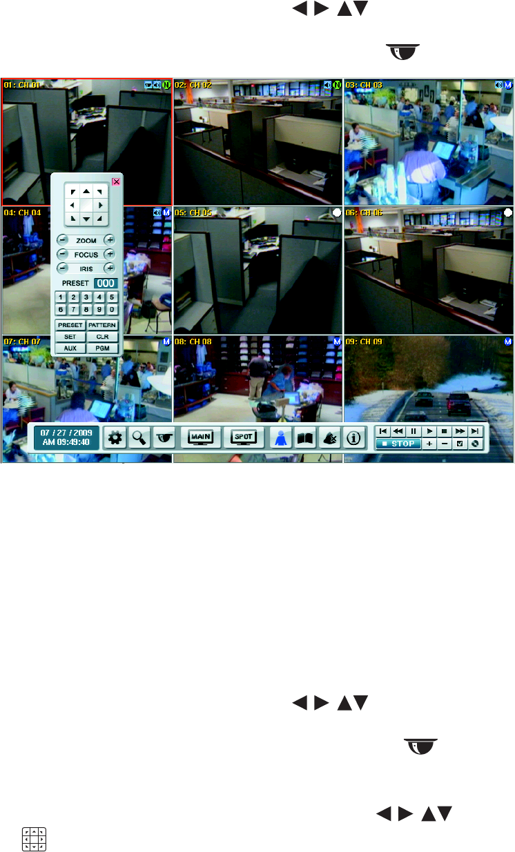
100 C2674M-C (7/09)
ACTIVATING PRESETS
1. On the front panel or remote control, press any of the arrow buttons to select a camera pane. Using the mouse, click a
camera pane. A red border highlights the selected pane.
2. Press PTZ on the front panel or the remote control. Using the mouse, click the PTZ button . The PTZ control is displayed.
Figure 102. PTZ Operation
3. On the front panel or remote control, press the preset number, and then press SHIFT + PRESET. Using the mouse, click the number pad on
the PTZ control, and then click PRESET. The camera moves to the preset location.
ACTIVATING PATTERNS
A pattern is a user-defined, viewable camera path with a specified beginning and end. Patterns are made up of a sequence of standard pan/tilt
and lens commands. Patterns are stored in the internal memory of the PTZ device, such as a Spectra® dome, connected to the DX4500/DX4600.
Spectra III™ supports one pattern and the Spectra III SE supports up to four unique PTZ patterns. Depending on the type and configuration of the
PTZ device, the DX4500/DX4600 can address up to four unique PTZ patterns. Once defined, a pattern can be activated with a series of on-screen
commands and will run continuously until it is deactivated.
To activate a pattern:
1. On the front panel or remote control, press any of the arrow buttons to select a camera pane. Using the mouse, click a
camera pane.
2. On the front panel or on the remote control, press PTZ. Using the mouse, click the PTZ button . The PTZ control is displayed.
3. On the front panel or remote control, press the pattern number, and then press SHIFT + PATTERN. Using the mouse, click the number pad on
the PTZ control, and then click PATTERN. The pattern runs.
4. To halt the pattern, on the front panel or remote control, press any of the arrow buttons . Using the mouse, click the move
buttons .

C2674M-C (7/09) 101
SENDING AUXILIARY COMMANDS TO A DEVICE
The DX4500/DX4600 auxiliary feature allows you to control external equipment connected to the auxiliary outputs of Spectra domes or Esprit®
positioning systems. The auxiliary function is implemented through Pelco D and Pelco P protocols.
The AUX key selects the auxiliary mode. Buttons 1–4 select the camera’s auxiliary outputs and operate as an on/off toggle.
For example, an Esprit equipped with a wiper uses Aux 1 to control the wiper. In this case, sending an AUX 1 command to the Esprit operates the
wiper. You must configure the camera to establish how the camera responds to an auxiliary command. For detailed information about how a
specific Spectra or Esprit camera system interprets auxiliary commands, refer to the documentation that accompanies the camera system.
To send an Aux 1 command to operate the wiper on an Esprit:
1. On the front panel or remote control, press any of the arrow buttons to select a PTZ camera. Using the mouse, click the
camera.
2. On the front panel or remote control press PTZ. Using the mouse, click the PTZ button . The PTZ control is displayed.
3. Enter the PTZ programming mode.
• On the front panel, press SHIFT + SET.
• On the remote control, press SET.
• Using the mouse, click SET.
4. Send an AUX 1 command.
• On the front panel, press SHIFT + AUX, and then press 1.
• On the remote control, press AUX, and then press 1.
• Using the mouse, click AUX, and then click 1.
The wiper operates one cycle.
PTZ PRESETS
A preset is a user-defined camera position using PTZ and focus commands (the camera’s auto focus option must be turned off). The DX4500/
DX4600 preset range is 0–255. For information about the number of presets supported by a given camera, refer to the documentation supplied
with the camera.
Programming a Preset
1. On the front panel or remote control, press any of the arrow buttons to select a PTZ camera pane. Using the mouse, click
a camera pane.
2. On the front panel or remote control, press PTZ. Using the mouse, click the PTZ button . The PTZ control is displayed.
3. Position, zoom, and focus the camera.
a. On the front panel or remote control, press any of the arrow buttons to move the camera. Using the mouse, click the
Move buttons .
b. On the front panel, press SHIFT + ZOOM or remote control, press ZOOM. Using the mouse, click ZOOM.
c. On the front panel, press SHIFT + FOCUS- or FOCUS+. On the remote control, press FOCUS. Using the mouse, click FOCUS.
4. Store the preset to a memory location.
a. On the front panel, press SHIFT + SET or remote control, press SET. Using the mouse, click SET. The camera is now in the programming
mode.
b. On the front panel or remote control, press a number representing the preset memory location. Using the mouse, click a number on the
keypad.
c. On the front panel, press SHIFT + PRESET. On the remote control, press PRESET. Using the mouse, click PRESET. The camera’s position,
zoom factor, and focus setting are stored to the memory location.
5. Do one of the following:
• To create multiple presets for the same camera, repeat steps 3 and 4.
• To exit the programming mode, on the front panel, press SHIFT + SET. On the remote control, press SET. Using the mouse, click SET.

102 C2674M-C (7/09)
6. Verify that you can activate the preset.
a. On the front panel or remote control, press any of the arrow buttons to move the camera to another location. Using
the mouse, click the Move buttons .
b. If you changed the camera’s zoom or focus, verify that the settings are different than the preset settings.
c. Do one of the following:
• On the front panel, press the preset number, and then press SHIFT + PRESET.
• On the remote control, press the preset number, and then press PRESET.
• Using the mouse, click the preset number, and then click PRESET.
The camera performs the programmed preset.
Preset Tours
A preset tour allows a camera to move through a programmed sequence of PTZ presets. The DX4500/DX4600 tour advances sequentially through
presets 1–16. There is approximately a four-second pause between the end of the current preset and the start of the next preset. If the presets
are programmed sequentially (1, 2, 3, 4, and so forth), the time period between presets is brief. If one or more of the presets are not programmed
sequentially, the time period between the end of the current preset and the start of the next can be longer, because the system still accounts for
the four-second interval for the non programmed preset memory location. For example, if presets 1 and 2 are programmed and presets 3–16 are
not programmed, the system waits approximately 54 seconds before starting preset 1.
A preset tour will operate continuously until another PTZ control action is performed. At least one PTZ preset must be set in order to create a
preset tour.
To activate a preset tour:
1. Click the PRESET button without entering a preset number. This activates a preset tour for all PTZ-enabled cameras.
Clearing a Preset
1. On the front panel, press SHIFT + SET. On the remote control, press SET. Using the mouse, click SET.
2. On the front panel, press SHIFT + PRESET. On the remote control, press PRESET. Using the mouse, click PRESET.
3. On the front panel or remote control, press a number representing the preset memory location. Using the mouse, click a number.
4. On the front panel, press SHIFT + CLR. On the remote control, press CLR. Using the mouse, click CLR. The preset is cleared from the
camera’s memory.
PTZ PATTERNS
Programming a Pattern
1. On the front panel, press SHIFT + SET or remote control, press SET. Using the mouse, click SET. The camera is now in the programming
mode.
2. On the front panel or remote control, press a number representing the pattern (1–4). Using the mouse, click a number.
3. On the front panel, press SHIFT + PATTERN. On the remote control, press PATTERN. Using the mouse, click PATTERN.
(Certain PTZ devices, such as Pelco’s Spectra series domes, will display an on-screen message with the amount of remaining memory
available for pattern programming.)
4. Move the camera through a series of movements using the on-screen PTZ and focus controls.
a. On the front panel or remote control, press any of the arrow buttons to move the camera. Using the mouse, click the
Move buttons .
b. On the front panel, press SHIFT + ZOOM or remote control, press ZOOM. Using the mouse, click ZOOM.
c. On the front panel, press SHIFT + FOCUS- or FOCUS+. On the remote control, press FOCUS. Using the mouse, click FOCUS.
5. Stop programming the pattern.
a. On the front panel, press SHIFT + PATTERN. On the remote control, press PATTERN. Using the mouse, click PATTERN.
b. On the front panel, press SHIFT + SET. On the remote control, press SET. Using the mouse, click SET.

C2674M-C (7/09) 103
6. Verify the pattern can be activated.
• On the front panel, press the pattern number, and then press SHIFT + PATTERN.
• On the remote control, press the patter number, and then press PATTERN.
• Using the mouse, click the pattern number, and then click PATTERN.
The pattern executes.
7. To stop the pattern, on the front panel or remote control, press any of the arrow buttons . Using the mouse, click the Move
buttons .
Clearing a Pattern
1. On the front panel, press SHIFT + SET. On the remote control, press SET. Using the mouse, click SET.
2. On the front panel or remote control, press a number representing the preset memory location. Using the mouse, click a number.
3. On the front panel, press SHIFT + PATTERN. On the remote control, press PATTERN. Using the mouse, click PATTERN.
4. On the front panel, press SHIFT + CLR. On the remote control, press CLR. Using the mouse, click CLR. The preset is cleared from the
camera’s memory.
ACCESSING PROGRAMMING FEATURES OF A REMOTE CAMERA
You can use the PTZ function to program features of cameras, such as Pelco’s Spectra or Esprit. Only cameras that support remote programming
through Pelco D, Pelco P, or supported third-party protocols can use this feature.
Access the camera programming menu for a PTZ camera.
1. On the front panel or remote control, press any of the arrow buttons to select a PTZ camera pane. Using the mouse, click
a camera pane.
2. On the front panel or remote control, press PTZ. Using the mouse, click the PTZ button . The PTZ control is displayed.
3. On the front panel or remote control, press MENU/ESC. Using the mouse, click PGM. The camera’s programming menu is displayed.
You can also display the camera setup menu by enter SET > 95 > PRESET.
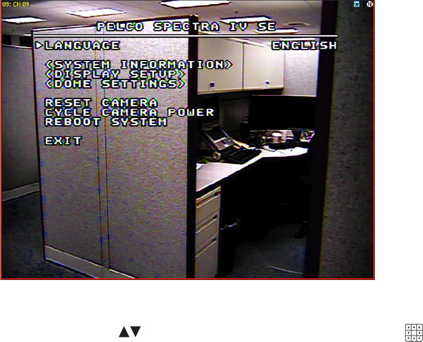
104 C2674M-C (7/09)
Figure 103. Camera Setup Menu
4. Move up and down through camera menu choices.
• Press the up/down arrow buttons on the front panel and remote control. Using the mouse, click the Move buttons .
• Press SHIFT + FOCUS+ on the front panel, and then press FOCUS+ or FOCUS-.
NOTE: After you press SHIFT, you can use the front panel FOCUS and IRIS buttons without having to press SHIFT again.
• On the remote control, press FOCUS+ and FOCUS-.
• Using the mouse, click FOCUS+ and FOCUS-.
5. Select an option from a menu item.
• Press IRIS+ on the front panel.
• On the remote control, press IRIS+.
• Using the mouse, click IRIS+.
6. Cancel an option or select the Exit command.
• Press IRIS- on the front panel.
• On the remote control, press IRIS-.
• Using the mouse, click IRIS-.

C2674M-C (7/09) 105
COPYING AND EXPORTING VIDEO
The DX4500/DX4600 allows you to copy and export recorded video from the hard drive to an external storage device (USB drive, CD, and
DVD±RW). For information about copying and exporting video, refer to Exporting Video on page 126.
ACKNOWLEDGING AN ALARM OR MOTION EVENT
The DX4500/DX4600 allows you to manually acknowledge an event state that has activated a relay output. By default, the DVR’s output relay is
turned off at a time commensurate with expiration of the post-alarm time. Acknowledging an alarm or motion event does not end the alarm or
motion event recording. The post-alarm time (configured under that Record menu) determines the time period for alarm recording. For information
about configuring the relay off setting, refer to Relay Outputs on page 56. For information about configuring the post-alarm time, refer to
Schedule Menu Setup on page 37.
The alarm acknowledged feature contains the following:
•Output: A relay associated with a channel and linked to an alarm input. If the relay is configured for alarm acknowledged, the relay output
is activated until it is manually deactivated.
•Sound alerts: The system menu includes the sound option that enables a sound alert in response to an unacknowledged event.
•Visible indicators The alarm and motion event displays an indicator in the camera pane. The indicator is visible for the length of time set
by the post-alarm time.
•Remote notification: Mail notification and emergency notification are used to alert the remote user that an event has occurred. When
viewing the remote client application, and event is not physically evidenced by the display of alarm or motion indicators.
To acknowledge an event, do one of the following:
• On the front panel, press SHIFT + ALM.OFF.
• On the remote control, press ALM.OFF.
• Using the mouse, click the Alarm OFF button .
The event is acknowledged and the relay output is deactivated. If sound is enabled, it is turned off.
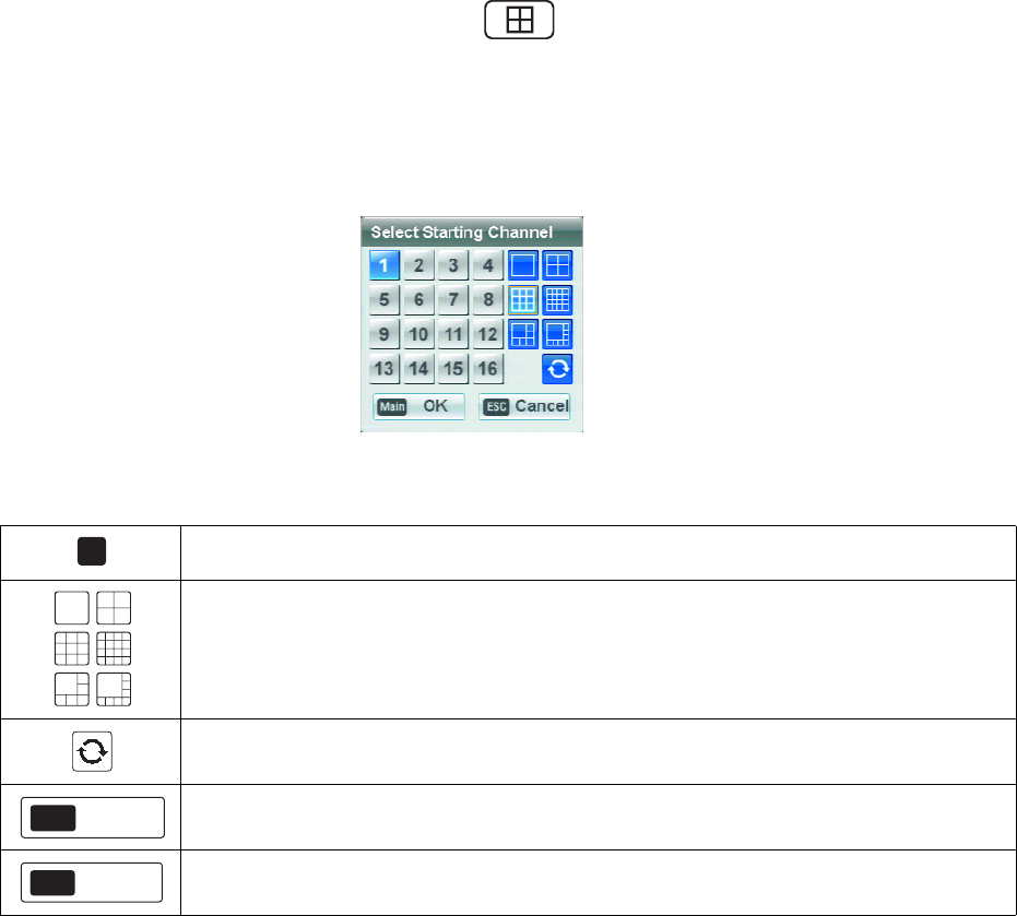
106 C2674M-C (7/09)
Main and Spot Monitors
MAIN MONITOR
1. On the front panel and remote control, press the MAIN button . Using the mouse, click the MAIN icon. The Select Starting
Channel dialog box opens.
2. Select a live view display format. The application window reorganizes the display format to the new setting.
3. On the front panel and remote control, press ENTER. Using the mouse, click OK to accept the setting.
4. To display a screen in full screen mode, double-click the desired channel.
Figure 104. Select Starting Channel, Main Monitor
Channel: Selects the main channel and is displayed in the upper left pane. The remaining channels are
sequentially numbered starting from the main channel.
Display: Selects the number of channels displayed in the application window. The main monitor output can be
adjusted to display one, four, nine, or sixteen cameras; or it can be adjusted for a one-plus-four or one-plus-seven
display.
Sequence: Displays each channel in sequence.
Accept: Accepts the change.
Cancel: Cancels the change.
1
OK
Main
Cancel
ESC
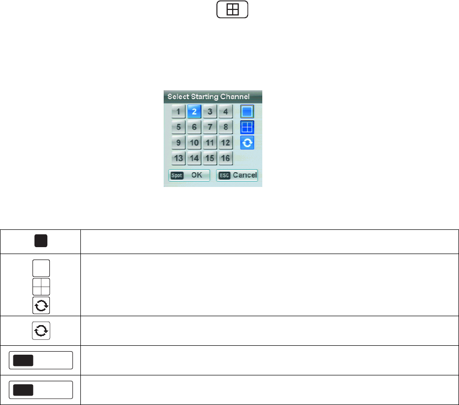
C2674M-C (7/09) 107
SPOT MONITOR
1. On the front panel and remote control, press the SPOT button , Using the mouse, click the SPOT icon on the toolbar. The spot
monitor Select Starting Channel dialog box opens.
2. Select a display format. On the front panel and remote control, press ENTER. Using the mouse, click OK to accept the setting. The
application window reorganizes the display format of the new setting.
3. To display the screen in full screen mode, double-click the desired channel.
Figure 105. Select Starting Channel, Spot Monitor
SELECTING THE MAIN VIDEO OUTPUT MONITORS
The main video output can be displayed on a VGA or analog monitor; video cannot be displayed on both monitors simultaneously. By default,
main video is displayed through the VGA connector. In this case, if a VGA monitor is connected to the VGA connector, video from the DVR is
displayed on the monitor.
The main or spot monitor can only be selected through the DX4500/DX4600 front panel.
DISPLAYING VIDEO ON THE ANALOG MONITOR
To change the video display from the VGA monitor to the analog monitor:
1. Connect the analog monitor to the MAIN-OUT BNC.
2. Turn on the analog monitor (the power source must be AC 100~240V, 50/60Hz).
3. On the front panel, press and hold the SPOT button. After approximately five seconds, the system will beep and restart.
4. Verify the main video display on the analog monitor.
Channel: Selects the spot channel, which is displayed in the upper left pane. The remaining channels are
sequentially numbered starting from the main channel.
Display: Selects the number of channels displayed in the application window. The spot monitor output can be
adjusted to display one or four cameras.
Sequence: Displays each channel in sequence.
Accept: the change.
Cancel: Cancels the change.
1
OK
Main
Cancel
ESC
108 C2674M-C (7/09)
DISPLAYING VIDEO ON THE VGA MONITOR
To change the video display from the analog monitor to the VGA monitor:
1. Connect the VGA monitor to the VGA connector.
2. Turn on the monitor.
3. On the front panel, press and hold the MAIN button. After approximately five seconds the system will beep and restart.
4. Verify the main video display on the VGA monitor.
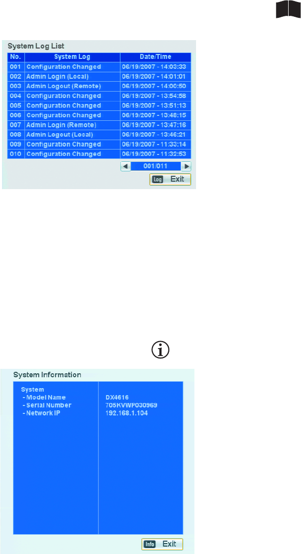
C2674M-C (7/09) 109
System Log and Information
LOG LIST
The system log provides a chronology of events by description, date, and time. You must log on to the system to view the system log.
1. On the front panel, press SHIFT + LOG. Press LOG on the remote control. Using the mouse, click the System Log icon . The System
Log List is displayed.
Figure 106. System Log List
INFORMATION
System Information contains both static and dynamic information. You can view the system’s model name, serial number, and network IP address
without logging on to the unit.
•Static information: Information that does not change including the model name and serial number. Pelco assigns a serial number to each
DVR. Use the Pelco serial number when corresponding with Pelco about your unit. The MAC address is an internal number.
•Dynamic information: Video format, TCP/IP settings, software version, and hard disk information.
1. To view system information, do one of the following:
•View the model, serial number, and IP address: Without logging on to the unit, on the front panel, press SHIFT + INFO. Press
INFO on the remote control. Using the mouse, click the Information icon . The System Information dialog box appears.
Figure 107. Short System Information Dialog Box
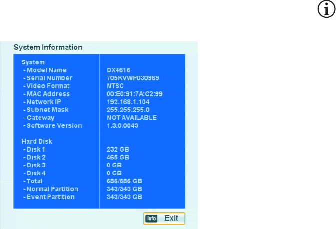
110 C2674M-C (7/09)
•View all system information: Any user can view system information.
(1) Log on to the unit.
(2) On the front panel, press SHIFT + INFO. Press INFO on the remote control. Using the mouse, click the Information icon .
The System Information dialog box appears.
Figure 108. Example: System Information
C2674M-C (7/09) 111
Playback Video
The DX4500/DX4600 supports two playback modes: playback and instant playback. The playback mode is accessed from the search window and
is used by the search feature to display video resulting from a search operation. Playback video is displayed in PIP presentation in the application
window. For information about the instant playback mode, refer to Instant Playback on page 97.
PLAYBACK VIEW AND CONTROLS
The playback mode has the following conditions:
•Playback: By default, playback video is displayed in PIP in the center of the application window. One, four, nine, or sixteen channels can
be simultaneously viewed in a custom display. One playback channel is displayed in a single pane, two to four playback channels are
displayed in four views, five to nine playback channels are displayed in nine views, and ten or more channels are displayed in sixteen panes
across the entire window. When sixteen channels are displayed simultaneously, the playback window cannot be moved and live video
cannot be viewed. However, the DVR continues to record video.
•Viewing video: The Client application plays back most, but not all, of the video frames received from the DVR server. Conversely, the DVR
server plays back video in it’s entirety. Therefore, video played back and viewed on the server, when played back and viewed on the Client,
does not include all video frames.
•Selecting playback panes: Multiple panes can be selected one at a time in the playback mode. A red border highlights the selected
pane.
•Playback controls: All playback channels are controlled simultaneously. An operation performed on one channel is automatically
performed on all playback channels.
•Supported search modes: With exception to the bookmark search feature, the playback mode is available for all other search modes.
The bookmark button is unavailable if an external backup device is selected.
•DVR operation: Recorded video can be viewed in the playback mode while simultaneously viewing and recording live video.
•Timing: Playback can be configured to begin two minutes prior to the start of an event.
In summary, to playback video:
1. Open the search window.
2. Search a channel for data.
3. From the search window, start playback. The playback video is displayed in PIP presentation.
4. Use the front panel, remote control buttons, or mouse to work with the PIP presentation.
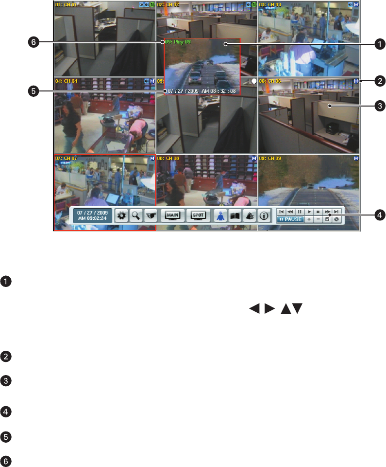
112 C2674M-C (7/09)
Figure 109. Playback Video
Playback Video Pane: Displays video in a picture-in-picture (PIP) presentation, which can overlap the source channel pane.
• Depending on the number of channels, PIP views can be displayed in 1, 4, 9, and 16 format.
• On the front panel and remote control, use any of the arrow buttons to move the playback video PIP pane to
another location. Using a mouse, right-click and drag the pane.
• Press the zoom buttons on the front panel or remote control to enlarge or reduce the PIP pane by 1x, 4x, or full screen.
Recording Indicator: Indicates motion recording mode.
Channel: Displays live video simultaneously and independently of the channel’s playback video being displayed in a separate
pane.
GUI Toolbar: For more information about playback controls, refer to the GUI Toolbar in Figure 2 on page 13.
Playback Date and Time: Playback video date and time stamp. Time period is displayed in the 24-hour format.
Playback Channel: Shows that the channel is in playback mode.
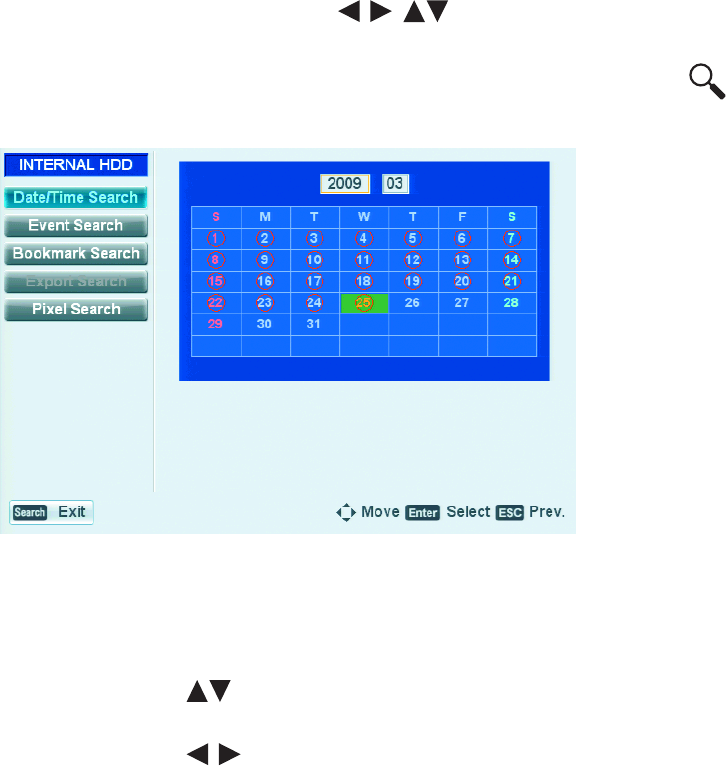
C2674M-C (7/09) 113
Searching for Video Events
SEARCH MEDIA
The DX4500/DX4600 supports five search modes: date/time, event, bookmark, export, and pixel search. The search feature can search for video
stored on the HDD, USB drive, and optical drives.
1. On the front panel or remote control, press any of the arrow buttons to select a camera pane. Using the mouse, click a
camera pane. A red border highlights the selected pane.
2. To display the search window, on the front panel or remote control, press SEARCH. Using the mouse, click the Search icon .
By default, the cursor moves to the Date/Time Search option. The current month’s calendar is displayed.
Figure 110. Search Window
3. The default internal HDD is the search media. Select the media on which to conduct the search.
• On the front panel or remote control, do the following:
(1) Press MENU/ESC. The Date/Time Search option is highlighted.
(2) Press the up/down arrow buttons to move to the media settings box, and then press ENTER. The media settings box
changes color.
(3) Press the left/right arrow buttons to display a media, and then press ENTER. The media settings box changes color.
• Using the mouse, click INTERNAL HDD, and then click the settings box.
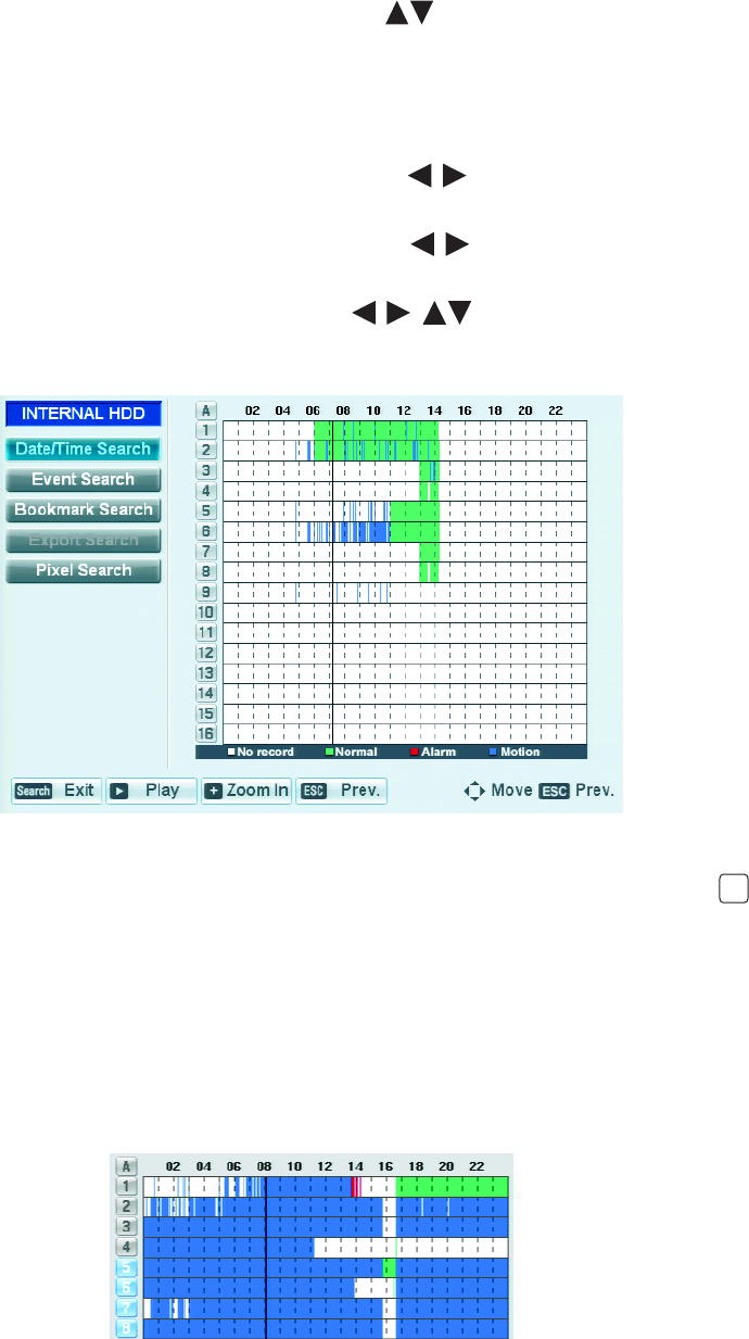
114 C2674M-C (7/09)
DATE/TIME SEARCH
To conduct a date and time search:
1. On the front panel or remote control, press the up/down arrow buttons to move to the Date/Time Search option, and then press
ENTER. Using the mouse, click the Date/Time Search option. The year settings box is highlighted in the current month’s calendar.
2. To select a date, do the following:
a. Accept or change the year entry in the settings box. To change the setting, on the front panel or remote control, press ENTER. Using
the mouse, click the settings box. The settings box changes color.
(1) On the front panel or remote, press the left/right arrow buttons to display the desired year, and then press ENTER. The
settings box changes color.
(2) On the front panel or remote, press the left/right arrow buttons to move to the month settings box, and then press
ENTER. Using the mouse, click the month’s setting box.
b. On the front panel or remote, press any of the arrow buttons to select the day of the month. Then press ENTER.
Using the mouse, click the day of the month. The Date/Time search results dialog box opens, displaying the search results for the
selected day. The cursor indicates the current time.
Figure 111. Date/Time Search Results
3. Select one or more channels from which to playback video. You can select channels individually or press the “A” button to select all of
the channels at once.
a. Do one of the following:
•DX4508/DX4608: On the front panel or remote control, press a number button for the channel.
•DX4516/DX4616: On the front panel or remote control, press a number button for the channel, and then press ENTER.
• Using the mouse, click the channel button.
The channel button changes color.
b. Repeat step 3a to select additional channels.
Figure 112. Selected Channels for Playback
A
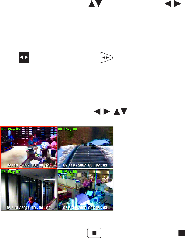
C2674M-C (7/09) 115
c. On the front panel or remote control, press the up/down arrow buttons or the left/right arrow buttons to move the
timeline to select the playback start time.
• The up/down arrow buttons move the timeline in 40-minute increments
• The left/right arrow buttons arrows move the timeline in 4-minute increments.
• Using the mouse, click the location.
d. To play back video from the selected channels, do the following:
• On the front panel, press Play . On the remote control, press Play .
• Using the mouse, click Play.
The playback window is displayed. (In this case, video playback is displayed in a four display view because four channels are
selected.)
• Use the playback controls to play back video. For example, you can pause, forward (frame-by-frame), reverse, zoom, and
bookmark played back video.
• On the front panel or remote control, press any of the arrow buttons to move the playback window. Using the
mouse, right-click and drag the window.
Figure 113. Date/Time Search Playback Video
4. To exit playback, on the front panel or remote control, press the Stop button . Using the mouse, click the Stop icon .
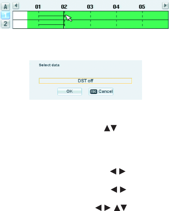
116 C2674M-C (7/09)
DST DATE/TIME SEARCH
If the DX4500/DX4600 is configured for DST, the DVR uses a different approach to store and display video. When DST is set to OFF, the DVR’s
internal time automatically adjusts backward one hour. Video is time-stamped and recorded one hour before and one hour after the time change.
When DST is set to ON, the DVR’s internal time automatically adjusts forward one hour and the unit records normally.
The Date/Time search feature allows you to view video recorded before and after a DST time change (refer to Figure 115). For example, the DVR
is configured for DST to end at 2:00 p.m. on November 4, 2007. The time period between column 01 and column 02 for channel 1 is partitioned
into two sections: the upper section represents video recorded when DST is set to ON, the bottom section represents video recorded when DST
is set to OFF.
Figure 114. Video Recorded Before and After DST Changed
When you initiate playback, the “Select data” dialog box prompts you to select a time period from which to display video: (“DST off” or “DST
on”).
Figure 115. Select Data Dialog Box
To conduct a DST date and time search:
1. On the front panel or remote control, press the up/down arrow buttons to move to the Date/Time Search option, and then press
ENTER. Using the mouse, click the Date/Time Search option. The year settings box is highlighted in the current month’s calendar.
2. To select the DST date, do the following:
a. Accept or change the year entry in the settings box. To change the setting, on the front panel or remote control, press ENTER. Using
the mouse, click the settings box. The settings box changes color.
(1) On the front panel or remote, press the left/right arrow buttons to display the desired year, and then press ENTER. The
settings box changes color.
(2) On the front panel or remote, press the left/right arrow buttons to move to the month settings box, and then press
ENTER. Using the mouse, click the month’s setting box.
b. On the front panel or remote, press any of the arrow buttons to select the day of the month. Then press ENTER.
Using the mouse, click the day of the month. The Date/Time search results dialog box opens, displaying the search results for the
selected day. The cursor indicates the current time.
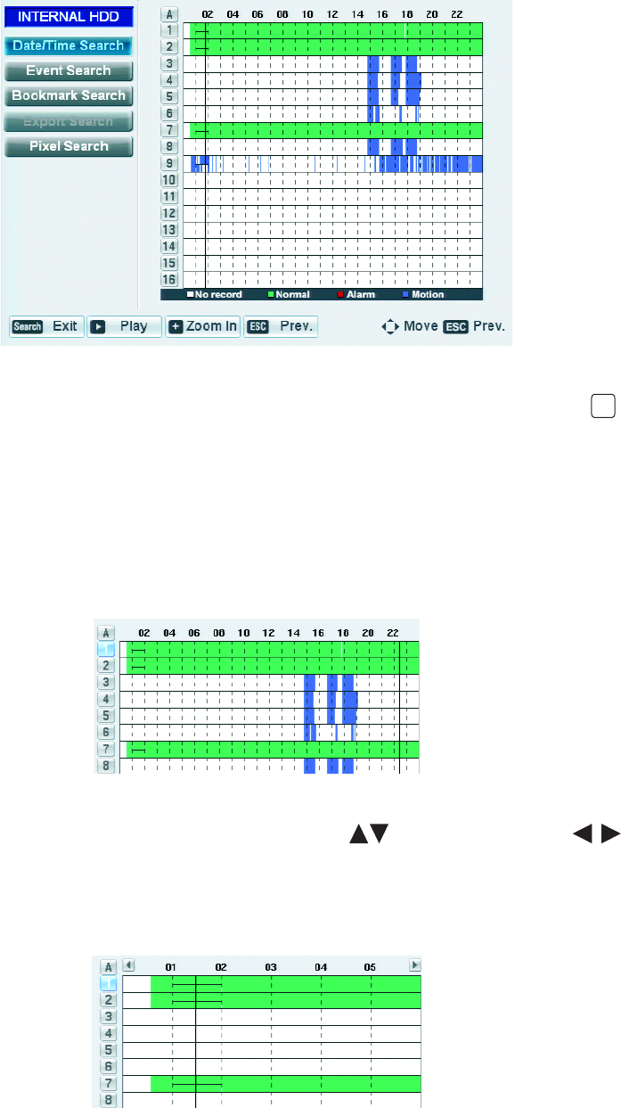
C2674M-C (7/09) 117
Figure 116. Date/Time Search Results
3. Select one or more channels from which to playback video. You can select channels individually or press the “A” button to select all of
the channels at once.
a. Do one of the following:
•DX4508/DX4608: On the front panel or remote control, press a number button for the channel.
•DX4516/DX4616: On the front panel or remote control, press a number button for the channel, and then press ENTER.
• Using the mouse, click the channel button.
The channel button changes color.
b. Repeat step 3a to select additional channels.
Figure 117. Selected Channels for DST Playback
c. On the front panel or remote control, press the up/down arrow buttons or the left/right arrow buttons to move the
timeline to select the DST time period to start playback.
• The up/down arrow buttons move the timeline in 40-minute increments
• The left/right arrow buttons arrows move the timeline in 4-minute increments.
• Using the mouse, click the location.
Figure 118. Timeline Position in DST Time Period
A
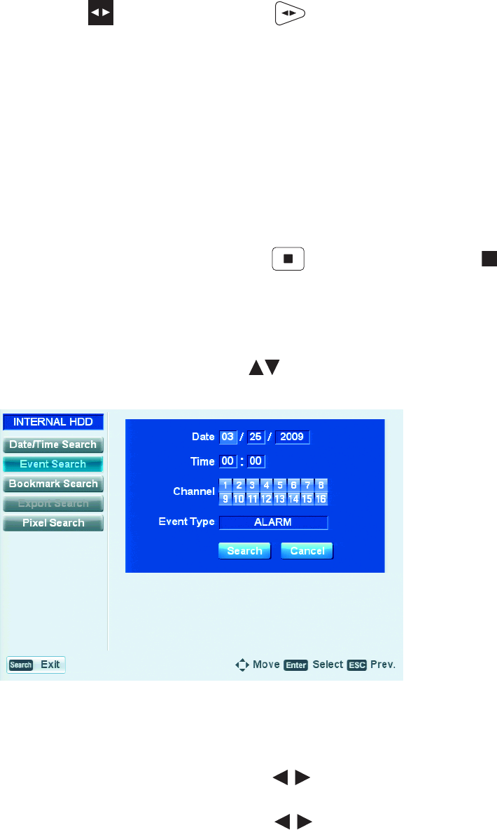
118 C2674M-C (7/09)
4. To play back video from the selected channels, do one of the following:
• On the front panel, press Play . On the remote control, press Play .
• Using the mouse, click Play.
The Select data dialog box opens.
• To play back video recorded with DST set to OFF, click OK.
• To play back video recorded with DST set to ON, double-click Select data settings box, and then click OK.
Played back video is displayed in the application window. When DST is set to OFF, the playback timeline data displays in green; when DST
is set to ON, it displays in white.
Use the playback controls to play back video. For example, you can pause, forward (frame-by-frame), reverse, zoom, and bookmark played
back video.
You can also adjust or move the playback window. On the front panel or remote control, press any of the arrow buttons (insert icons) to
move the window. Using the mouse, right-click and drag the window.
5. To exit playback, on the front panel or remote control, press the Stop button . Using the mouse, click the Stop icon .
EVENT SEARCH
Conduct an event search.
1. On the front panel or remote control, press the up/down arrow buttons to move to the Event Search option, and then press ENTER.
Using the mouse, click the Event Search option. The month settings box is highlighted.
Figure 119. Event Search
2. Change the month setting.
a. On the front panel or remote control, press ENTER. Using the mouse, click the settings box. The settings box changes color.
b. On the front panel or remote control, press the left/right arrow buttons to display a month, and then press ENTER. Using the
mouse, right- or left-click the settings box. The settings box changes color.
c. On the front panel or remote control, press the left/right arrow buttons to move to the day of the month. Repeat step 2b to
select the day.
d. Repeat step 2c to select the year.
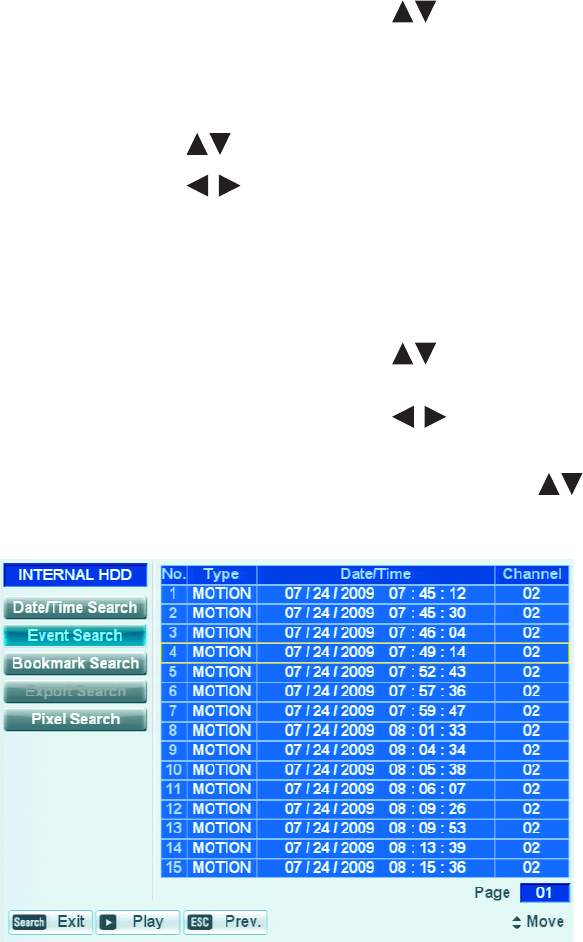
C2674M-C (7/09) 119
3. Select the time.
a. On the front panel or remote control, press the up/down arrow buttons to select the hours settings hour box.
b. Repeat the procedure to select the minutes.
4. Select the channels.
• On the front panel or remote control.
(1) Press the up/down arrow buttons to move to the channels settings box
(2) Press the left/right arrow buttons to select the channel, and then press ENTER. The channel number button changes
color.
(3) Repeat step 4(2) to select additional channels.
• Using the mouse, click a channel number.
5. Select the event type.
a. On the front panel or remote control, press the up/down arrow buttons to select the Event Type settings box, and then press
ENTER. Using the mouse, click the settings box. The settings box changes color.
b. On the front panel or remote control, press the left/right arrow buttons to display the Event Type, and then press ENTER.
Using the mouse, right- or left-click the settings box. The settings box changes color.
6. To initiate the event search, on the front panel or remote control, press the up/down arrow buttons to highlight the Event Search
button. Then press ENTER. Using the mouse, click Event Search. The playback window displays the recorded events for the specified search
criteria.
Figure 120. Event Search Results
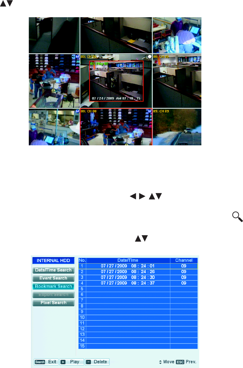
120 C2674M-C (7/09)
7. The cursor highlights the first entry in the list. To play back video, on the front panel or remote control, press the up/down arrow buttons
to highlight a search result in the list and then press PLAY. Using the mouse, click a search result. The PIP pane is displayed in the
center of the application window. Refer to Figure 121.
Figure 121. Event Playback Video in PIP Pane
BOOKMARK SEARCH
The bookmark search feature allows you to search for recorded video that has been previously bookmarked. This feature is not available for
searching backed up data.
1. On the front panel or remote control, press any of the arrow buttons to select a camera pane. Using the mouse, click a
camera pane. A red border highlights the selected pane.
2. To display the search window, on the front panel or remote control, press SEARCH. Using the mouse, click the Search icon .
The cursor moves to the Date/Time Search option.
3. On the front panel or remote control, press the up/down arrow buttons to move to the Bookmark Search option, and then press
ENTER. Using the mouse, click the Bookmark Search button. The bookmark table is displayed.
Figure 122. Bookmark Search
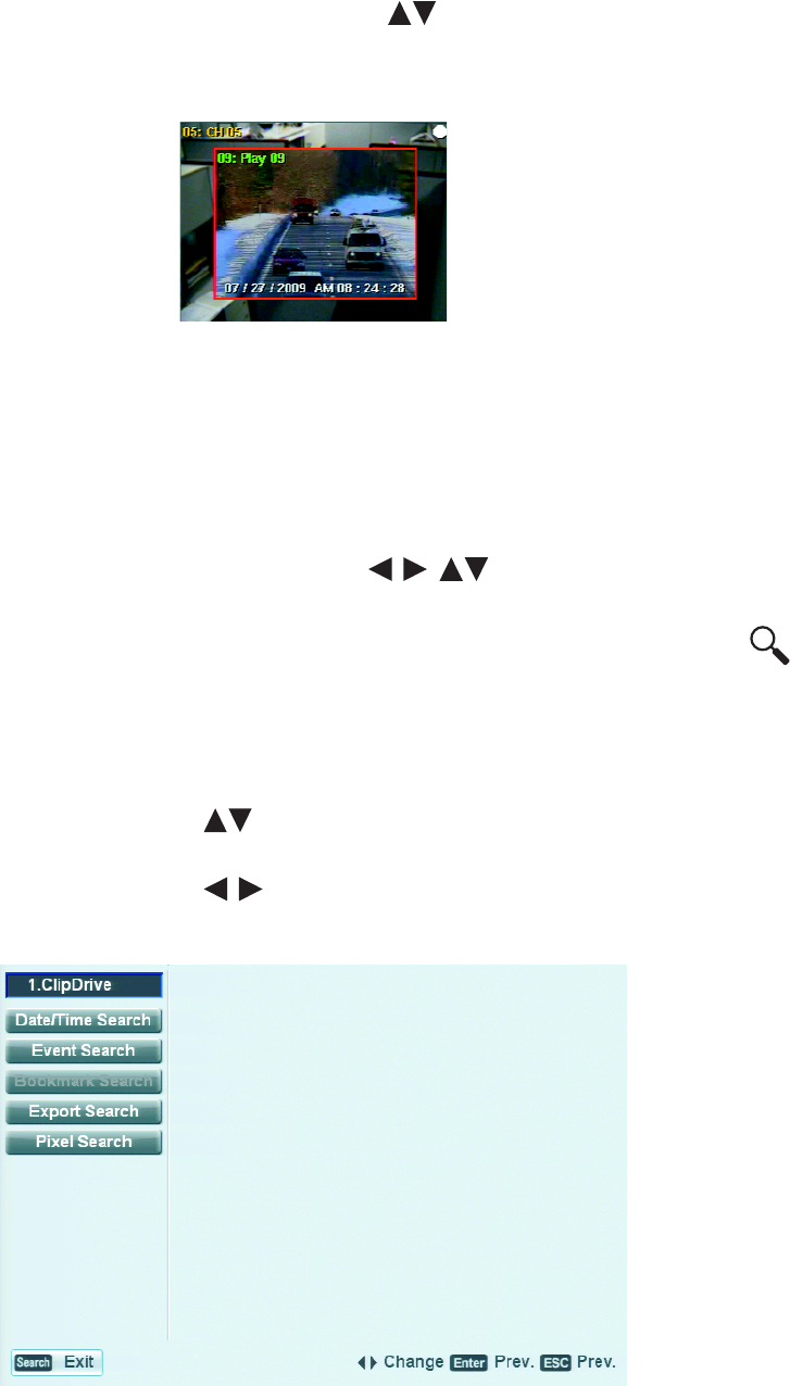
C2674M-C (7/09) 121
4. On the front panel or remote control, press the up/down arrow buttons to highlight a search result in the table. Using the mouse,
click the search result.
5. On the front panel or remote control, press PLAY. Using the mouse, click Play. The bookmarked video is played in the PIP pane.
Figure 123. Playback of Bookmarked Video
EXPORT SEARCH
The DX4500/DX4600 allows you to export data to CD/DVD or USB media. Use the export search feature to search a media for exported video.
Use the DX4500/DX4600 play, pause, and stop playback controls to preview exported video.
This feature is not available for searching backed up data. For information about exporting data, refer to Exporting Video on page 126.
1. On the front panel or remote control, press any of the arrow buttons to select a camera pane. Using the mouse, click a
camera pane. A red border highlights the selected pane.
2. To display the search window, on the front panel or remote control, press SEARCH. Using the mouse, click the Search icon .
The cursor moves to the Date/Time Search option.
3. The default internal HDD is the search media. Select the media on which to conduct the search.
• On the front panel or remote control, do the following:
(1) Press MENU/ESC. The Date/Time Search option is highlighted.
(2) Press the up/down arrow buttons to move to the media settings box, and then press ENTER. The media settings box
changes color.
(3) Press the left/right arrow buttons to display a media, and then press ENTER. The media settings box changes color.
• Using the mouse, click the media settings box to display a media.
Figure 124. Selecting a Media Type
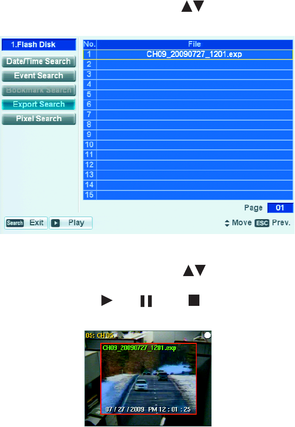
122 C2674M-C (7/09)
4. On the front panel or remote control, press the up/down arrow buttons to move to the Export Search option, and then press ENTER.
Using the mouse, click the Export Search option. The export table appears.
Figure 125. Export Search
5. On the front panel or remote control, press the up/down arrow buttons to highlight a search result in the table. Using the mouse,
click the search result. The exported video is played in the PIP pane.
NOTE: The DX4500/DX4600 supports the play , pause , and stop buttons when playing back exported video. The reverse start,
reverse, forward, end playback controls are not supported.
Figure 126. Playback of Exported Video
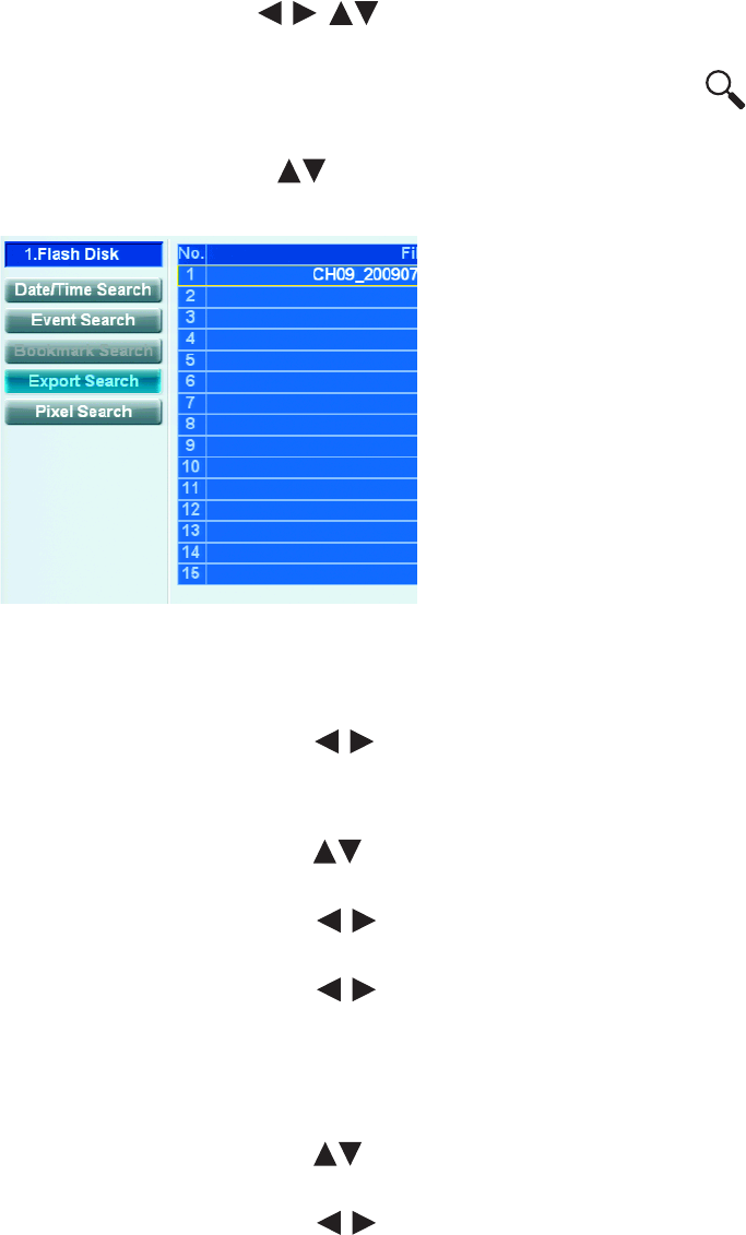
C2674M-C (7/09) 123
PIXEL SEARCH
1. On the front panel or remote control, press any of the arrow buttons to select a camera pane. Using the mouse, click a
camera pane. A red border highlights the selected pane.
2. To display the search window, on the front panel or remote control, and then press SEARCH. Using the mouse, click the Search icon
The cursor moves to the Date/Time Search option.
3. On the front panel or remote control, press the up/down arrow buttons to highlight Pixel Search, and then press ENTER. Using the
mouse, click the Pixel Search option. The pixel search calendar is displayed. The Channel option settings box is highlighted.
Figure 127. Pixel Search Calendar
4. Select the channel.
a. On the front panel or remote control, press ENTER. Using the mouse, click the settings box. The settings box changes color.
b. On the front panel or remote control, press the left/right arrow buttons to display the channel, and then press ENTER. Using
the mouse, right- or left-click the settings box.
5. Select the start date and time.
a. On the front panel or remote control, press the up/down arrow buttons to select the hour settings box, and then press ENTER.
Using the mouse, click the settings box. The settings box changes color.
b. On the front panel or remote control, press the left/right arrow buttons to display the month, and then press ENTER. Using
the mouse, right- or left-click the settings box. The settings box changes color.
c. On the front panel or remote control, press the left/right arrow buttons to select the day of the month.
d. Repeat step 5b to select the day and Step 5c to select the year.
6. Repeat the procedure in step 5 to set the end date and time.
7. Set the sensitivity.
a. On the front panel or remote control, press the up/down arrow buttons to highlight the Sensitivity settings hour box, and then
press ENTER. Using the mouse, click the settings box. The settings box changes color.
b. On the front panel or remote control, press the left/right arrow buttons to display the Sensitivity level, and then press
ENTER. Using the mouse, right- or left-click the settings box. The settings box changes color.
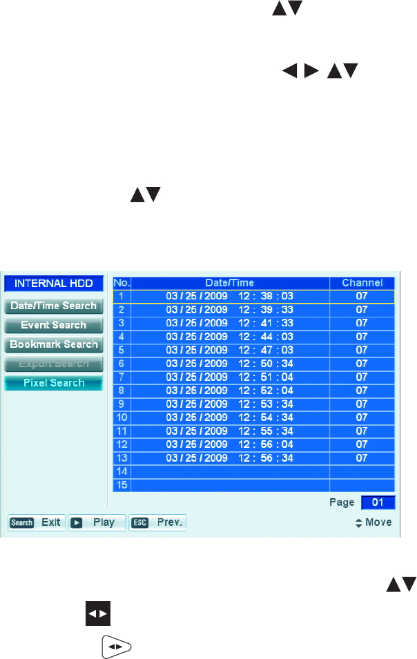
124 C2674M-C (7/09)
8. Set the area.
a. On the front panel or remote control, press the up/down arrow buttons to highlight the SET button, and then press ENTER.
Using the mouse, click the Set button. The pixel window is available and the selected camera’s video view is displayed.
b. Do one of the following:
• On the front panel or remote control, press any of the arrow buttons to move to a pixel in the search, and then
press ENTER. Repeat this process until you have defined the search area.
• Using the mouse, left-click and drag the selection box to define the search area. The pixels in the selected area change color.
9. Exit the pixel window and start the pixel search operation.
• On the front panel or remote control.
(1) Press MENU/ESC. The Set button is highlighted.
(2) Press the up/down arrow buttons to highlight the Pixel Search button, and press ENTER.
• Using the mouse, click the Pixel Search button.
The system searches for recorded video the matches the search area defined by the selected pixels. The search results are displayed.
Figure 128. Pixel Search Results
10. To view the pixel search video, on the front panel or remote control, press the up/down arrow buttons to highlight a row.
• On the front panel press Play .
• On the remote control press Play .
• Using the mouse, click a row, and then click Play.
The playback video is displayed in the PIP pane.

C2674M-C (7/09) 125
BOOKMARK PLAYBACK
The DX4500/DX4600 allows you to bookmark playback or instant playback video for quick retrieval or later use. Use the bookmark feature during
playback to mark import events. The bookmarks are retained with the recorded data until the bookmarks are deleted.
NOTE: The DX4500/DX4600 allows you to bookmark up to a maximum of 15 entries.
BOOKMARKING VIDEO
1. On the front panel or remote control, press any of the arrow buttons to select a camera pane. Using the mouse, click a
camera pane. A red border highlights the selected pane.
2. To display the search window, on the front panel or remote control, press SEARCH. Using the mouse, click the Search icon .
The cursor moves to the Date/Time Search option. For information about using the Search feature, refer to Searching for Video Events on
page 113.
3. On the front panel or remote control, press the up/down arrow buttons to move to a Search option and then press ENTER. Using the
mouse, click the Date/Time Search option. The Search calendar is displayed.
4. Use the DVR controls to enter the search criteria: date, time, channel, and so forth.
5. Start the search to locate the recorded video. The results are stored in a table.
6. Play back and review the searched video, do the following:
7. To bookmark a specific scene:
• On the front panel, press SHIFT + MARK.
• On the remote control, press MARK.
• Using the mouse, click the Copy/Export icon .
The bookmark is saved.
VIEWING BOOKMARKED VIDEO
1. On the front panel or remote control, press any of the arrow buttons to select a camera pane. Using the mouse, click a
camera pane. A red border highlights the selected pane.
2. To display the search window, on the front panel or remote control, press SEARCH. Using the mouse, click the Search Icon .
The cursor moves to the Date/Time Search option.
3. On the front panel or remote control, press the up/down arrow buttons to move to the Bookmark Search button, and then press
ENTER. The bookmark results are displayed in a table.
4. On the front panel or remote control, press the up/down arrow buttons to highlight a search result. Using the mouse, click a search
result.
5. On the front panel or remote control, press the up/down arrow buttons to highlight Play, and then press ENTER. Using the mouse,
click Play. Playback video is displayed in the application window.
CLEARING BOOKMARKS
1. To display the search window, on the front panel or remote control, press SEARCH. Using the mouse, click the Search Icon .
The cursor moves to the Date/Time Search option.
2. On the front panel or remote control, press the up/down arrow buttons to move to the Bookmark Search button, and then press
ENTER. The bookmark results are displayed in a table.
3. On the front panel or remote control, press the up/down arrow buttons to highlight a search result. Using the mouse, click a search
result.
4. To clear the bookmark, on the front panel or remote control, press ZOOM-. Using the mouse, click the search result, and then click Delete.
126 C2674M-C (7/09)
Exporting Video
The DX4500/DX4600 allows you to export data to CD/DVD or USB media and then preview that data. For information about previewing exported
video, refer to
NOTES:
• When exporting data, the start time must be set a minimum of two minutes earlier than the current time.
• The DX4500/DX4600 recorded video time stamp is affected by differing time zones. When video recorded on the DX4500/DX4600 server
located in one time zone (for example, GMT -8:00) is exported and played back on a computer located in a different time zone (for example,
GMT -5:00), the video's original recording time adjusts and displays based on the time zone of the playback computer. To play back exported
video so its original recording time displays correctly, the time zone setting of the playback computer must be identically configured to the
time zone of the DX4500/DX4600 server on which the video was recorded.
1. Do one of the following:
• On the front panel, press SHIFT + Copy.
• On the remote control, press the Copy button .
• Using the mouse, click the Copy/Export button .
The Copy/Export dialog box is displayed. The Target Device settings box is highlighted.
2. Define the export criteria.
a. On the front panel or remote control, press ENTER. Using the mouse, click the settings box. The settings box changes color.
b. Do one of the following:
• On the front panel or remote control, press the left/right arrow buttons to display the Target Device, and then press
ENTER.
• Using the mouse, right- or left-click the settings box, and then click the Channel 1 button.
The Target Device settings box changes color.
c. Do one of the following:
• On the front panel or remote control, press any of the arrow buttons to highlight the channel number from
which you want to export video, and then press ENTER.
• Using the mouse, click the channel button.
The channel button changes color.
d. Repeat step c to select additional channels.
3. Select the start date and time.
a. On the front panel or remote control, press the up/down arrow buttons to select the hour settings box, and then press ENTER.
Using the mouse, click the settings box. The settings box changes color.
b. On the front panel or remote control, press the left/right arrow buttons to display the month, and then press ENTER. Using
the mouse, right- or left-click the settings box. The settings box changes color.
c. On the front panel or remote control, press the left/right arrow buttons to move to the day of the month.
d. Repeat step 3b to select the day and repeat step 3c to select the year.
4. Repeat the procedure in step 3 to set the End Date/Time.
5. Do one of the following:
• On the front panel, press SHIFT + Copy.
• On the remote control, press the Copy button .
• Using the mouse, click Copy/Export.
If the export settings are correct, the system exports the data to the target device and then displays a message stating the export process is
complete. If the settings are not correct, the system displays a message stating the process is incomplete.
6. On the front panel or remote control, press ENTER. Using the mouse, click OK.

C2674M-C (7/09) 127
Appendix A
DX4500/DX4600 FACTORY DEFAULTS
Table G. Factory Default Settings (Sheet 1 of 4)
Menu Command Option Property Default Setting Factory
Default
Client
Application
Camera Properties Name DX4516/DX4616: CH01–16
DX4508/DX4608: CH 01–08
Yes Yes
Covert OFF Yes Yes
Audio DX4516/DX4616: 01–04, NONE
DX4508/DX4608: 01– 02, NONE
Yes Yes
Camera Disable OFF Yes Yes
Video Adjustment Channel CH01 Yes
Brightness 50 Yes No
Contrast 50 Yes No
Color 50 Yes No
Restore to Default Restore to Default Yes
PTZ Channel CH01 Yes
Port NONE Yes Yes
Address 00 Yes Yes
Protocol PELCO_D Yes Yes
Baud Rate 9600 Yes Yes
PTZ Test
Video Video Format NTSC Yes No
Normal Record Channel 1–8 or 1–16 Yes
Resolution 352 X 240 Yes Yes
Quality STANDARD Yes Yes
Image rate 7.5 Yes Yes
Prealarm OFF Yes Yes
Postalarm 10 SEC Yes Yes
Alarm Record Resolution 352 X 240 Yes Yes
Quality STANDARD Yes Yes
Image rate 7.5 Yes Yes
Motion Record Resolution 352 X 240 Yes Yes
Quality STANDARD Yes Yes
Image rate 7.5 Yes Yes

128 C2674M-C (7/09)
Instant Record Resolution 352 X 240 Yes Yes
Quality STANDARD Yes Yes
Image rate 3 Yes Yes
Schedule Sun to Sat 1–8 or 1–16 Alarm/Motion Yes Yes
Holiday 1–8 or 1–16 No record Yes Yes
Display OSD Language ENGLISH Yes Yes
Channel Name ON Yes Yes
Channel Status ON Yes Yes
Main Monitor Dwell Time 2 SEC Yes Yes
Spot Monitor Dwell Time 2 SEC Yes Yes
Event Popup ALL Yes Yes
Covert Camera OFF Yes Yes
Linking Alarm 1–8 or 1–16 No
Input Type N.O. Yes Yes
Camera 01–08 or 01–16 Yes Yes
Relay Output 01–02 or 01–04 Yes Yes
Motion Channel CH01 Yes
Sensitivity 05 Yes Yes
Relay Output NONE Yes Yes
Area All selected Yes Yes
Output Relay Off ALARM ACKNOWLEDGE Yes Yes
Network TCP/IP DHCP ON Yes No
IP Address Unavailable Yes No
Subnet Mask Unavailable Yes No
Gateway Unavailable Yes No
Primary DNS Unavailable Yes No
Secondary DNS Unavailable Yes No
TCP/IP Port 9001 Yes No
Web Server Port 80 Yes No
Bandwidth Throttle 100 Mbps Yes Yes
DDNS User Name Unavailable Yes No
Password Unavailable Yes No
Notification Alarm On OFF Yes Yes
Motion Detection OFF Yes Yes
Disk Full OFF Yes Yes
Table G. Factory Default Settings (Sheet 2 of 4)
Menu Command Option Property Default Setting Factory
Default
Client
Application

C2674M-C (7/09) 129
Admin Password Changed OFF Yes Yes
Video Loss ON Yes Yes
Power On/Off ON Yes Yes
Network
(Continued)
Mail Notification OFF Yes Yes
SMTP Server Unavailable Yes Yes
SMTP Port Number 25 (Unavailable) Yes Yes
User Name Unavailable Yes Yes
Password Unavailable Yes Yes
TLS OFF (Unavailable) Yes
Mail Address 1 Unavailable Yes Yes
Mail Address 2 Unavailable Yes Yes
Mail Address 3 Unavailable Yes Yes
SMTP Server Test SMTP Server Test (Unavailable) Yes
Emergency Notification OFF Yes Yes
IP Address/Port IP Unavailable, Port = 9002 Yes Yes
System Date/Time Date 06/09/2009 PST No No
Time PM 01:33:06 PST No No
Date Format MM/DD/YYYY Yes Yes
Time Format 12 HR Yes
Time Zone GMT (-08:00) Yes No
Daylight Saving ON Yes No
Daylight Saving Start MAR 2nd, SUN 02 Yes No
Daylight Saving End NOV 1st, SUN 02 Yes
NTP NTP OFF Yes Yes
Server PUBLIC SERVER Yes Yes
Private Time Server Unavailable Yes Yes
Sync. Interval 1 Day (Unavailable) Yes Yes
NTP Test NTP Test No
Sound Button OFF Yes Yes
Alarm OFF Yes Yes
Motion OFF Yes Yes
System OFF Yes Yes
User Number 1–10
ID admin (Unavailable) No Yes
Level Administrator (Unavailable) No
Table G. Factory Default Settings (Sheet 3 of 4)
Menu Command Option Property Default Setting Factory
Default
Client
Application

130 C2674M-C (7/09)
Password hidden Yes
Update Selection SYSTEM S/W Yes Yes
Method USB Yes Yes
Update Server Unavailable Yes Yes
Update Update No
Configuration Configuration Import Import Yes
Configuration Export Export Yes
Factory Default Default Set No
Hard Disk Format ALL Yes
Overwrite ALL Yes Yes
Full Warning 90% Yes Yes
Event Partition 50% Yes No
Auto Delete OFF Yes
Backup Partition Selection ALL Yes
Schedule OFF Yes No
Device 1.ClipDrive (Unavailable) Yes
Schedule Start SUN 00:00 (Unavailable) Yes No
Time Range Date 06/09/2009 (Unavailable) Yes No
Time Range Start SUN 00:00 (Unavailable) Yes No
Time Range End SUN 00:00 (Unavailable) Yes No
Estimate Size Unavailable Yes
Start Backup Unavailable Yes
Erase Media Unavailable Yes
System ID IR Remote ID 01 Yes No
Auto User Logout OFF Yes
Table G. Factory Default Settings (Sheet 4 of 4)
Menu Command Option Property Default Setting Factory
Default
Client
Application

C2674M-C (7/09) 131
Appendix B
TIME ZONE CONVERSION CHART
To determine your time, add the standard, daylight saving, or summer time to the Universal Time (UT).
Table H. Time Zone Conversion Chart
Time Zone Standard Time Daylight Saving and
Summer Time
International Date Line East (IDLE) +12 hours
New Zealand Standard Time (NZST) +12 hours
New Zealand Time (NZT) +10 hours
Guam Standard Time (GST) +10 hours
Australian Eastern Standard Time (AEST) (AEDT) +10 hours +11 hours
Australian Central Standard Time (ACST) (ACDT) +9.5 hours +10.5 hours
Japan Standard Time (JST) +9 hours
China Coast Time (CCT) +8 hours
Australian Western Standard Time (AWST) +8 hours
India Standard Time (IST) +5.5 hours
Russian Zone 3 +4 hours
Baghdad Time (BT) +3 hours
Russian Zone 2 +3 hours
Moscow Time (MSK) (MSD) +3 hours +4 hours
Eastern European Time (EET) (EEST) +2 hours +3 hours
Russian Zone 1 +2 hours
Central Europe Summer Time (CEST) +2 hours
Central European Time (CET) +1 hour
Middle European Time (MET) +1 hour
Swedish Winter Time (SWT) 0 hours
Greenwich Mean Time (GMT) 0 hours
Universal Time (UT) 0 hours
Western European Time (WET) (WEST) 0 hours +1 hour
British Summer Time (BST) +1 hour
Irish Summer Time (IST) +1 hour
West African Time (WAT) -1 hour
Newfoundland Standard Time (NST) (NDT) -3.5 hours -2.5 hours
Atlantic Standard Time (AST) (ADT) -4 hours -3 hours
Eastern Standard Time (EST) (EDT) -5 hours -4 hours
Central Standard Time (CST) (CDT) -6 hours -5 hours
Mountain Standard Time (MST) (MDT) -7 hours -6 hours
Pacific Standard Time (PST) (PDT) -8 hours -7 hours
Alaskan Standard Time (AKST) (AKDT) -9 hours -8 hours
Hawaiian Standard Time (HST) -10 hours
International Date Line West (IDLW) -12 hours

PRODUCT WARRANTY AND RETURN INFORMATION
WARRANTY
Pelco will repair or replace, without charge, any merchandise proved defective in
material or workmanship for a period of one year after the date of shipment.
Exceptions to this warranty are as noted below:
• Five years:
– Fiber optic products
– TW3000 Series unshielded twisted pair (UTP) transmission products
– CC3701H-2, CC3701H-2X, CC3751H-2, CC3651H-2X, MC3651H-2, and
MC3651H-2X camera models
• Three years:
– Pelco-branded fixed camera models (CCC1390H Series, C10DN Series,
C10CH Series, IP3701H Series, and IX Series)
– EH1500 Series enclosures
– Spectra® IV products (including Spectra IV IP)
– Camclosure® Series (IS, ICS, IP) integrated camera systems
– DX Series digital video recorders, DVR5100 Series digital video recorders,
Digital Sentry® Series hardware products, DVX Series digital video
recorders, and NVR300 Series network video recorders
– Endura® Series distributed network-based video products
– Genex® Series products (multiplexers, server, and keyboard)
– PMCL200/300/400 Series LCD monitors
• Two years:
– Standard varifocal, fixed focal, and motorized zoom lenses
– DF5/DF8 Series fixed dome products
– Legacy® Series integrated positioning systems
– Spectra III™, Spectra Mini, Spectra Mini IP, Esprit®, ExSite®, and PS20
scanners, including when used in continuous motion applications.
– Esprit Ti and TI2500 Series thermal imaging products
– Esprit and WW5700 Series window wiper (excluding wiper blades).
– CM6700/CM6800/CM9700 Series matrix
– Digital Light Processing (DLP®) displays (except lamp and color wheel). The
lamp and color wheel will be covered for a period of 90 days. The air filter is
not covered under warranty.
– Intelli-M® eIDC controllers
• One year:
– Video cassette recorders (VCRs), except video heads. Video heads will be
covered for a period of six months.
•Six months:
– All pan and tilts, scanners, or preset lenses used in continuous motion
applications (preset scan, tour, and auto scan modes).
Pelco will warrant all replacement parts and repairs for 90 days from the date of
Pelco shipment. All goods requiring warranty repair shall be sent freight prepaid
to a Pelco designated location. Repairs made necessary by reason of misuse,
alteration, normal wear, or accident are not covered under this warranty.
Pelco assumes no risk and shall be subject to no liability for damages or loss
resulting from the specific use or application made of the Products. Pelco’s liability
for any claim, whether based on breach of contract, negligence, infringement of
any rights of any party or product liability, relating to the Products shall not exceed
the price paid by the Dealer to Pelco for such Products. In no event will Pelco be
liable for any special, incidental, or consequential damages (including loss of use,
loss of profit, and claims of third parties) however caused, whether by the
negligence of Pelco or otherwise.
The above warranty provides the Dealer with specific legal rights. The Dealer may
also have additional rights, which are subject to variation from state to state.
If a warranty repair is required, the Dealer must contact Pelco at (800) 289-9100 or
(559) 292-1981 to obtain a Repair Authorization number (RA), and provide the
following information:
1. Model and serial number
2. Date of shipment, P.O. number, sales order number, or Pelco invoice number
3. Details of the defect or problem
If there is a dispute regarding the warranty of a product that does not fall under
the warranty conditions stated above, please include a written explanation with
the product when returned.
Method of return shipment shall be the same or equal to the method by which the
item was received by Pelco.
RETURNS
To expedite parts returned for repair or credit, please call Pelco at (800) 289-9100
or (559) 292-1981 to obtain an authorization number (CA number if returned for
credit, and RA number if returned for repair) and designated return location.
All merchandise returned for credit may be subject to a 20 percent restocking and
refurbishing charge.
Goods returned for repair or credit should be clearly identified with the assigned
CA or RA number and freight should be prepaid.
The materials used in the manufacture of this document and its components are compliant to the requirements of Directive 2002/95/EC.
This equipment contains electrical or electronic components that must be recycled properly to comply with Directive 2002/96/EC of the European Union
regarding the disposal of waste electrical and electronic equipment (WEEE). Contact your local dealer for procedures for recycling this equipment.
12-23-08
REVISION HISTORY
Manual # Date Comments
C2674M 8/07 Original version.
C2674M-A 1/08 Updated DST feature and PTZ information. Added an appendix section with Time Zone Conversion Chart.
C2674M-B 11/08 Updated the Emergency Agent description in the Network Menu Setup section and added information about working with the recorded video time stamp to the
Exporting Video section.
C2674M-C 7/09 Updated with new features: KBD300A support, playback of exported data on the server, Pelco C support, and multi-event recording.
Pelco, the Pelco logo, Camclosure, Digital Sentry, Endura, Esprit, ExSite, Genex, Intelli-M, Legacy, and Spectra are registered trademarks of Pelco, Inc. © Copyright 2009, Pelco, Inc. All rights reserved.
DLP is a registered trademark of Texas Instruments Incorporated.
All product names and services identified throughout this document are trademarks or registered trademarks of their respective companies.
The absence of a trademark or registered trademark from this document does not constitute a waiver of intellectual property rights.