Pelco PMCL500 Series HD Narrow Bezel LCD Monitor User Manual To The 1e200b0b Efa7 4079 82b9 8ca64c8328e4
User Manual: Pelco PMCL500 to the manual
Open the PDF directly: View PDF ![]() .
.
Page Count: 32
- PMCL500 Series FHD Narrow Bezel LCD Monitor
- Contents
- List of Illustrations
- List of Tables
- Important Notices
- Important Safety Instructions
- Description
- Installation
- Operation
- Troubleshooting
- Specifications
INSTALLATION/OPERATION
C2988M-A (6/11)
42-, 46-, and 55-Inch Models
PMCL500 Series
FHD Narrow Bezel
LCD Monitor

C2988M-A (6/11) 3
Contents
Important Notices . . . . . . . . . . . . . . . . . . . . . . . . . . . . . . . . . . . . . . . . . . . . . . . . . . . . . . . . . . . . . . . . . . . . . . . . . . . . . . . . . . . . . . . . . . . . . . . . . . . . . 6
Regulatory Notices . . . . . . . . . . . . . . . . . . . . . . . . . . . . . . . . . . . . . . . . . . . . . . . . . . . . . . . . . . . . . . . . . . . . . . . . . . . . . . . . . . . . . . . . . . . . . . . . 6
Important Safety Instructions . . . . . . . . . . . . . . . . . . . . . . . . . . . . . . . . . . . . . . . . . . . . . . . . . . . . . . . . . . . . . . . . . . . . . . . . . . . . . . . . . . . . . . . . . . . . 7
Description. . . . . . . . . . . . . . . . . . . . . . . . . . . . . . . . . . . . . . . . . . . . . . . . . . . . . . . . . . . . . . . . . . . . . . . . . . . . . . . . . . . . . . . . . . . . . . . . . . . . . . . . . . . 8
Models . . . . . . . . . . . . . . . . . . . . . . . . . . . . . . . . . . . . . . . . . . . . . . . . . . . . . . . . . . . . . . . . . . . . . . . . . . . . . . . . . . . . . . . . . . . . . . . . . . . . . . . . . 8
Recommended Mounts. . . . . . . . . . . . . . . . . . . . . . . . . . . . . . . . . . . . . . . . . . . . . . . . . . . . . . . . . . . . . . . . . . . . . . . . . . . . . . . . . . . . . . . . . . . . . 8
Package Contents . . . . . . . . . . . . . . . . . . . . . . . . . . . . . . . . . . . . . . . . . . . . . . . . . . . . . . . . . . . . . . . . . . . . . . . . . . . . . . . . . . . . . . . . . . . . . . . . . 9
User-Supplied Parts . . . . . . . . . . . . . . . . . . . . . . . . . . . . . . . . . . . . . . . . . . . . . . . . . . . . . . . . . . . . . . . . . . . . . . . . . . . . . . . . . . . . . . . . . . . . . . . 9
Indicator Lights, Controls, and Connections. . . . . . . . . . . . . . . . . . . . . . . . . . . . . . . . . . . . . . . . . . . . . . . . . . . . . . . . . . . . . . . . . . . . . . . . . . . . 10
Front Panel . . . . . . . . . . . . . . . . . . . . . . . . . . . . . . . . . . . . . . . . . . . . . . . . . . . . . . . . . . . . . . . . . . . . . . . . . . . . . . . . . . . . . . . . . . . . . . . . . 10
Control Panel . . . . . . . . . . . . . . . . . . . . . . . . . . . . . . . . . . . . . . . . . . . . . . . . . . . . . . . . . . . . . . . . . . . . . . . . . . . . . . . . . . . . . . . . . . . . . . . 10
On-Screen Display (OSD) Keypad Function List. . . . . . . . . . . . . . . . . . . . . . . . . . . . . . . . . . . . . . . . . . . . . . . . . . . . . . . . . . . . . . . . . . . . . 11
Connection Panel . . . . . . . . . . . . . . . . . . . . . . . . . . . . . . . . . . . . . . . . . . . . . . . . . . . . . . . . . . . . . . . . . . . . . . . . . . . . . . . . . . . . . . . . . . . 12
Installation . . . . . . . . . . . . . . . . . . . . . . . . . . . . . . . . . . . . . . . . . . . . . . . . . . . . . . . . . . . . . . . . . . . . . . . . . . . . . . . . . . . . . . . . . . . . . . . . . . . . . . . . . . 13
Setup. . . . . . . . . . . . . . . . . . . . . . . . . . . . . . . . . . . . . . . . . . . . . . . . . . . . . . . . . . . . . . . . . . . . . . . . . . . . . . . . . . . . . . . . . . . . . . . . . . . . . . . . . . 13
Unpacking . . . . . . . . . . . . . . . . . . . . . . . . . . . . . . . . . . . . . . . . . . . . . . . . . . . . . . . . . . . . . . . . . . . . . . . . . . . . . . . . . . . . . . . . . . . . . . . . . 13
Connecting Video Source Equipment . . . . . . . . . . . . . . . . . . . . . . . . . . . . . . . . . . . . . . . . . . . . . . . . . . . . . . . . . . . . . . . . . . . . . . . . . . . . 13
Connecting the Power Cord. . . . . . . . . . . . . . . . . . . . . . . . . . . . . . . . . . . . . . . . . . . . . . . . . . . . . . . . . . . . . . . . . . . . . . . . . . . . . . . . . . . . 13
Connecting the Infrared (IR) Extender . . . . . . . . . . . . . . . . . . . . . . . . . . . . . . . . . . . . . . . . . . . . . . . . . . . . . . . . . . . . . . . . . . . . . . . . . . . . 13
Connecting to Video Equipment . . . . . . . . . . . . . . . . . . . . . . . . . . . . . . . . . . . . . . . . . . . . . . . . . . . . . . . . . . . . . . . . . . . . . . . . . . . . . . . . 13
Connecting to Video Sources. . . . . . . . . . . . . . . . . . . . . . . . . . . . . . . . . . . . . . . . . . . . . . . . . . . . . . . . . . . . . . . . . . . . . . . . . . . . . . . . . . . 13
Connecting to a Computer . . . . . . . . . . . . . . . . . . . . . . . . . . . . . . . . . . . . . . . . . . . . . . . . . . . . . . . . . . . . . . . . . . . . . . . . . . . . . . . . . . . . . 13
Operation . . . . . . . . . . . . . . . . . . . . . . . . . . . . . . . . . . . . . . . . . . . . . . . . . . . . . . . . . . . . . . . . . . . . . . . . . . . . . . . . . . . . . . . . . . . . . . . . . . . . . . . . . . . 14
General Information . . . . . . . . . . . . . . . . . . . . . . . . . . . . . . . . . . . . . . . . . . . . . . . . . . . . . . . . . . . . . . . . . . . . . . . . . . . . . . . . . . . . . . . . . . . . . . 14
Connecting the Power Cable . . . . . . . . . . . . . . . . . . . . . . . . . . . . . . . . . . . . . . . . . . . . . . . . . . . . . . . . . . . . . . . . . . . . . . . . . . . . . . . . . . . 14
Turning Power On . . . . . . . . . . . . . . . . . . . . . . . . . . . . . . . . . . . . . . . . . . . . . . . . . . . . . . . . . . . . . . . . . . . . . . . . . . . . . . . . . . . . . . . . . . . 14
Selecting Input Source. . . . . . . . . . . . . . . . . . . . . . . . . . . . . . . . . . . . . . . . . . . . . . . . . . . . . . . . . . . . . . . . . . . . . . . . . . . . . . . . . . . . . . . . 14
Turning Power Off . . . . . . . . . . . . . . . . . . . . . . . . . . . . . . . . . . . . . . . . . . . . . . . . . . . . . . . . . . . . . . . . . . . . . . . . . . . . . . . . . . . . . . . . . . . 14
Using the Menu Screen . . . . . . . . . . . . . . . . . . . . . . . . . . . . . . . . . . . . . . . . . . . . . . . . . . . . . . . . . . . . . . . . . . . . . . . . . . . . . . . . . . . . . . . . . . . 15
Remote Control . . . . . . . . . . . . . . . . . . . . . . . . . . . . . . . . . . . . . . . . . . . . . . . . . . . . . . . . . . . . . . . . . . . . . . . . . . . . . . . . . . . . . . . . . . . . . 15
On-Screen Display (OSD) Menus . . . . . . . . . . . . . . . . . . . . . . . . . . . . . . . . . . . . . . . . . . . . . . . . . . . . . . . . . . . . . . . . . . . . . . . . . . . . . . . . . . . . 16
Image Settings . . . . . . . . . . . . . . . . . . . . . . . . . . . . . . . . . . . . . . . . . . . . . . . . . . . . . . . . . . . . . . . . . . . . . . . . . . . . . . . . . . . . . . . . . . . . . . . . . . 16
Display Settings . . . . . . . . . . . . . . . . . . . . . . . . . . . . . . . . . . . . . . . . . . . . . . . . . . . . . . . . . . . . . . . . . . . . . . . . . . . . . . . . . . . . . . . . . . . . . . . . . 17
Audio Settings . . . . . . . . . . . . . . . . . . . . . . . . . . . . . . . . . . . . . . . . . . . . . . . . . . . . . . . . . . . . . . . . . . . . . . . . . . . . . . . . . . . . . . . . . . . . . . . . . . 18
Basic Settings . . . . . . . . . . . . . . . . . . . . . . . . . . . . . . . . . . . . . . . . . . . . . . . . . . . . . . . . . . . . . . . . . . . . . . . . . . . . . . . . . . . . . . . . . . . . . . . . . . . 18
Real Time Clock . . . . . . . . . . . . . . . . . . . . . . . . . . . . . . . . . . . . . . . . . . . . . . . . . . . . . . . . . . . . . . . . . . . . . . . . . . . . . . . . . . . . . . . . . . . . . 18
Advanced Settings . . . . . . . . . . . . . . . . . . . . . . . . . . . . . . . . . . . . . . . . . . . . . . . . . . . . . . . . . . . . . . . . . . . . . . . . . . . . . . . . . . . . . . . . . . . . . . . 19
Video Wall . . . . . . . . . . . . . . . . . . . . . . . . . . . . . . . . . . . . . . . . . . . . . . . . . . . . . . . . . . . . . . . . . . . . . . . . . . . . . . . . . . . . . . . . . . . . . . . . . . . . . 19
Connection Types. . . . . . . . . . . . . . . . . . . . . . . . . . . . . . . . . . . . . . . . . . . . . . . . . . . . . . . . . . . . . . . . . . . . . . . . . . . . . . . . . . . . . . . . . . . . 19
Video Wall Parameters . . . . . . . . . . . . . . . . . . . . . . . . . . . . . . . . . . . . . . . . . . . . . . . . . . . . . . . . . . . . . . . . . . . . . . . . . . . . . . . . . . . . . . . 20
2 x 2 Video Wall Grid. . . . . . . . . . . . . . . . . . . . . . . . . . . . . . . . . . . . . . . . . . . . . . . . . . . . . . . . . . . . . . . . . . . . . . . . . . . . . . . . . . . . . . . . . 22
3 x 3 Video Wall Grid. . . . . . . . . . . . . . . . . . . . . . . . . . . . . . . . . . . . . . . . . . . . . . . . . . . . . . . . . . . . . . . . . . . . . . . . . . . . . . . . . . . . . . . . . 23
OSD Menu for Video Wall Setup. . . . . . . . . . . . . . . . . . . . . . . . . . . . . . . . . . . . . . . . . . . . . . . . . . . . . . . . . . . . . . . . . . . . . . . . . . . . . . . . 24
RS-232 Control. . . . . . . . . . . . . . . . . . . . . . . . . . . . . . . . . . . . . . . . . . . . . . . . . . . . . . . . . . . . . . . . . . . . . . . . . . . . . . . . . . . . . . . . . . . . . . 24
System Status Menu . . . . . . . . . . . . . . . . . . . . . . . . . . . . . . . . . . . . . . . . . . . . . . . . . . . . . . . . . . . . . . . . . . . . . . . . . . . . . . . . . . . . . . . . . . . . . 25
User Analog to Digital Converter (ADC) Calibration. . . . . . . . . . . . . . . . . . . . . . . . . . . . . . . . . . . . . . . . . . . . . . . . . . . . . . . . . . . . . . . . . . . . . . 25
Resolution Tables . . . . . . . . . . . . . . . . . . . . . . . . . . . . . . . . . . . . . . . . . . . . . . . . . . . . . . . . . . . . . . . . . . . . . . . . . . . . . . . . . . . . . . . . . . . . . . . . 26
Troubleshooting . . . . . . . . . . . . . . . . . . . . . . . . . . . . . . . . . . . . . . . . . . . . . . . . . . . . . . . . . . . . . . . . . . . . . . . . . . . . . . . . . . . . . . . . . . . . . . . . . . . . . . 27
Specifications . . . . . . . . . . . . . . . . . . . . . . . . . . . . . . . . . . . . . . . . . . . . . . . . . . . . . . . . . . . . . . . . . . . . . . . . . . . . . . . . . . . . . . . . . . . . . . . . . . . . . . . 28

4C2988M (6/11)
List of Illustrations
1 Package Contents . . . . . . . . . . . . . . . . . . . . . . . . . . . . . . . . . . . . . . . . . . . . . . . . . . . . . . . . . . . . . . . . . . . . . . . . . . . . . . . . . . . . . . . . . . . . . . . . . 9
2 Front Panel and Indicator Lights . . . . . . . . . . . . . . . . . . . . . . . . . . . . . . . . . . . . . . . . . . . . . . . . . . . . . . . . . . . . . . . . . . . . . . . . . . . . . . . . . . . . . 10
3 Control Panel and OSD Keypad . . . . . . . . . . . . . . . . . . . . . . . . . . . . . . . . . . . . . . . . . . . . . . . . . . . . . . . . . . . . . . . . . . . . . . . . . . . . . . . . . . . . . 10
4 OSD Keypad and Functions. . . . . . . . . . . . . . . . . . . . . . . . . . . . . . . . . . . . . . . . . . . . . . . . . . . . . . . . . . . . . . . . . . . . . . . . . . . . . . . . . . . . . . . . . 11
5 Connection Panel . . . . . . . . . . . . . . . . . . . . . . . . . . . . . . . . . . . . . . . . . . . . . . . . . . . . . . . . . . . . . . . . . . . . . . . . . . . . . . . . . . . . . . . . . . . . . . . . 12
6 Remote Control Functions. . . . . . . . . . . . . . . . . . . . . . . . . . . . . . . . . . . . . . . . . . . . . . . . . . . . . . . . . . . . . . . . . . . . . . . . . . . . . . . . . . . . . . . . . . 15
7 Video (BNC Type) Connection . . . . . . . . . . . . . . . . . . . . . . . . . . . . . . . . . . . . . . . . . . . . . . . . . . . . . . . . . . . . . . . . . . . . . . . . . . . . . . . . . . . . . . . 19
8 VGA Connection . . . . . . . . . . . . . . . . . . . . . . . . . . . . . . . . . . . . . . . . . . . . . . . . . . . . . . . . . . . . . . . . . . . . . . . . . . . . . . . . . . . . . . . . . . . . . . . . . 20
9 DVI Connection . . . . . . . . . . . . . . . . . . . . . . . . . . . . . . . . . . . . . . . . . . . . . . . . . . . . . . . . . . . . . . . . . . . . . . . . . . . . . . . . . . . . . . . . . . . . . . . . . . 20
10 Video Wall Display with Frame On. . . . . . . . . . . . . . . . . . . . . . . . . . . . . . . . . . . . . . . . . . . . . . . . . . . . . . . . . . . . . . . . . . . . . . . . . . . . . . . . . . . 21
11 Video Wall Display with Frame Off . . . . . . . . . . . . . . . . . . . . . . . . . . . . . . . . . . . . . . . . . . . . . . . . . . . . . . . . . . . . . . . . . . . . . . . . . . . . . . . . . . 21
12 2 x 2 Video Wall Grid . . . . . . . . . . . . . . . . . . . . . . . . . . . . . . . . . . . . . . . . . . . . . . . . . . . . . . . . . . . . . . . . . . . . . . . . . . . . . . . . . . . . . . . . . . . . . 22
13 3 x 3 Video Wall Grid . . . . . . . . . . . . . . . . . . . . . . . . . . . . . . . . . . . . . . . . . . . . . . . . . . . . . . . . . . . . . . . . . . . . . . . . . . . . . . . . . . . . . . . . . . . . . 23
14 RS-232 Connection . . . . . . . . . . . . . . . . . . . . . . . . . . . . . . . . . . . . . . . . . . . . . . . . . . . . . . . . . . . . . . . . . . . . . . . . . . . . . . . . . . . . . . . . . . . . . . . 24
15 User ADC Calibration . . . . . . . . . . . . . . . . . . . . . . . . . . . . . . . . . . . . . . . . . . . . . . . . . . . . . . . . . . . . . . . . . . . . . . . . . . . . . . . . . . . . . . . . . . . . . 25

C2988M (6/11) 5
List of Tables
A Light Indicators . . . . . . . . . . . . . . . . . . . . . . . . . . . . . . . . . . . . . . . . . . . . . . . . . . . . . . . . . . . . . . . . . . . . . . . . . . . . . . . . . . . . . . . . . . . . . . . . . . 10
B Connection Panel . . . . . . . . . . . . . . . . . . . . . . . . . . . . . . . . . . . . . . . . . . . . . . . . . . . . . . . . . . . . . . . . . . . . . . . . . . . . . . . . . . . . . . . . . . . . . . . . 12
C Image Settings . . . . . . . . . . . . . . . . . . . . . . . . . . . . . . . . . . . . . . . . . . . . . . . . . . . . . . . . . . . . . . . . . . . . . . . . . . . . . . . . . . . . . . . . . . . . . . . . . . 16
D Display Settings . . . . . . . . . . . . . . . . . . . . . . . . . . . . . . . . . . . . . . . . . . . . . . . . . . . . . . . . . . . . . . . . . . . . . . . . . . . . . . . . . . . . . . . . . . . . . . . . . 17
E Audio Settings . . . . . . . . . . . . . . . . . . . . . . . . . . . . . . . . . . . . . . . . . . . . . . . . . . . . . . . . . . . . . . . . . . . . . . . . . . . . . . . . . . . . . . . . . . . . . . . . . . 18
F Basic Settings . . . . . . . . . . . . . . . . . . . . . . . . . . . . . . . . . . . . . . . . . . . . . . . . . . . . . . . . . . . . . . . . . . . . . . . . . . . . . . . . . . . . . . . . . . . . . . . . . . . 18
G Real Time Clock Settings . . . . . . . . . . . . . . . . . . . . . . . . . . . . . . . . . . . . . . . . . . . . . . . . . . . . . . . . . . . . . . . . . . . . . . . . . . . . . . . . . . . . . . . . . . 18
H Advanced Settings . . . . . . . . . . . . . . . . . . . . . . . . . . . . . . . . . . . . . . . . . . . . . . . . . . . . . . . . . . . . . . . . . . . . . . . . . . . . . . . . . . . . . . . . . . . . . . . 19
I 2 x 2 Video Wall Parameters . . . . . . . . . . . . . . . . . . . . . . . . . . . . . . . . . . . . . . . . . . . . . . . . . . . . . . . . . . . . . . . . . . . . . . . . . . . . . . . . . . . . . . . 22
J 3 x 3 Video Wall Parameters . . . . . . . . . . . . . . . . . . . . . . . . . . . . . . . . . . . . . . . . . . . . . . . . . . . . . . . . . . . . . . . . . . . . . . . . . . . . . . . . . . . . . . . 23
K Composite/Component/S-Video Mode . . . . . . . . . . . . . . . . . . . . . . . . . . . . . . . . . . . . . . . . . . . . . . . . . . . . . . . . . . . . . . . . . . . . . . . . . . . . . . . 26
L DisplayPort/DVI/HDMI/VGA Mode . . . . . . . . . . . . . . . . . . . . . . . . . . . . . . . . . . . . . . . . . . . . . . . . . . . . . . . . . . . . . . . . . . . . . . . . . . . . . . . . . . 26
M Troubleshooting . . . . . . . . . . . . . . . . . . . . . . . . . . . . . . . . . . . . . . . . . . . . . . . . . . . . . . . . . . . . . . . . . . . . . . . . . . . . . . . . . . . . . . . . . . . . . . . . . 27
6C2988M-A (6/11)
Important Notices
REGULATORY NOTICES
This device complies with Part 15 of the FCC Rules. Operation is subject to the following two conditions: (1) this device may not cause
harmfulinterference, and (2) this device must accept any interference received, including interference that may cause undesired operation.
RADIO AND TELEVISION INTERFERENCE
This equipment has been tested and found to comply with the limits of a Class B digital device, pursuant to Part 15 of the FCC Rules. These limits
are designed to provide reasonable protection against harmful interference in a residential installation. This equipment generates, uses, and can
radiate radio frequency energy and, if not installed and used in accordance with the instructions, may cause harmful interference to radio
communications. However there is no guarantee that the interference will not occur in a particular installation. If this equipment does cause
harmful interference to radio or television reception, which can be determined by turning the equipment off and on, the user is encouraged to try
to correct the interference by one or more of the following measures:
• Reorient or relocate the receiving antenna.
• Increase the separation between the equipment and the receiver.
• Connect the equipment into an outlet on a circuit different from that to which the receiver is connected.
• Consult the dealer or an experienced radio/TV technician for help.
You may also find helpful the following booklet, prepared by the FCC: “How to Identify and Resolve Radio-TV Interference Problems.” This
booklet is available from the U.S. Government Printing Office, Washington D.C. 20402.
Changes and modifications not expressly approved by the manufacturer or registrant of this equipment can void your authority to operate this
equipment under Federal Communications Commission’s rules.
In order to maintain compliance with FCC regulations shielded cables must be used with this equipment. Operation with non-approved
equipment or unshielded cables is likely to result in interference to radio and television reception.
This Class B digital apparatus complies with Canadian ICES-003.
Cet appareil numérique de la classe B est conforme à la norme NMB-003 du Canada.
KOREAN CLASS B

C2988M-A (6/11) 7
Important Safety Instructions
This product is designed and manufactured to operate within defined design limits, and misuse may result in electric shock or fire. To prevent the
product from being damaged, the following rules should be observed for the installation, use and maintenance of the product. Read the following
safety instructions before operating the display. Keep these instructions in a safe place for future reference.
1. Read these instructions.
2. Keep these instructions.
3. Heed all warnings.
4. Follow all instructions.
5. Do not use this apparatus near water.
6. Clean only with dry cloth.
7. Do not block any ventilation openings. Install in accordance with the manufacturer’s instructions.
8. Do not install near any heat sources such as radiators, heat registers, stoves, or other apparatus (including amplifiers) that produce heat.
9. Do not defeat the safety purpose of the polarized or grounding-type plug. A polarized plug has two blades with one blade wider than the
other. A grounding plug has two blades and a third grounding prong. The wide blade or the third prong are provided for your safety. If the
provided plug does not fit into your outlet, consult an electrician for replacement of the obsolete outlet.
10. Protect the power cord from being walked on or pinched particularly at plugs, convenience receptacles, and the points where they exit from
the apparatus.
11. Only use attachments/accessories specified by the manufacturer.
12. Only use with the cart, stand, tripod, bracket, or table specified by the manufacturer, or sold with the apparatus. When a cart is used, use
caution when moving the cart/apparatus combination to avoid injury from tip-over.
13. Refer all servicing to qualified service personnel. Servicing is required when the apparatus has been damaged in any way, such as power-
supply cord or plug is damaged, liquid has been spilled or objects have fallen into the apparatus, the apparatus has been exposed to rain or
moisture, does not operate normally, or has been dropped.
14. Unplug the apparatus during lightning storms or when unused for long periods of time.
15. Apparatus shall not be exposed to dripping or splashing and no objects filled with liquids, such as vases shall be placed on the apparatus.
16. WARNING: To reduce the risk of fire or electric shock, do not expose this apparatus to rain or moisture.
17. Installation should be done only by qualified personnel and conform to all local codes.
18. Unless this unit is specifically marked as NEMA Type 3, 3R, 3S, 4, 4X, 6, or 6P enclosure, it is designed for indoor use only and it must not
be installed where exposed to rain and moisture.
19. Only use installation methods and materials capable of supporting four times the maximum specified load.
20. Only use replacement parts recommended by Pelco.
21. Avoid touching the screen directly with your fingers as the oils from your skin may be difficult to remove from the LCD.
22. Do not apply direct pressure on the screen.
23. Keep the monitor in a dust-free environment and away from strong electromagnetic fields.
24. Do not use attachments, such as mounts, that are not recommended by Pelco. They may be hazardous.
25. Do not place the monitor on an unstable stand, bracket, or mount. The unit may fall, causing serious damage to the unit or injury to a
person. Only use mounts recommended by Pelco.
26. A CCC-approved power cord must be used to power this equipment when used in China.
27. A still image displayed too long may cause permanent damage to the LCD panel. Watching the LCD in 4:3 format for a long time may leave
traces of borders displayed on the left, right and center of the screen caused by the difference of light emission on the screen. Using a
camera or a system may cause a similar effect to the screen. Damages caused by this effect are not covered by the warranty.
The product and/or manual may bear the following marks:
This symbol indicates that dangerous voltage constituting a risk of electric shock is present
within this unit.
This symbol indicates that there are important operating and maintenance instructions in
the literature accompanying this unit
CAUTION:
RISK OF ELECTRIC SHOCK.
DO NOT OPEN.

8C2988M-A (6/11)
Description
Pelco’s PMCL500 Series high-definition narrow bezel (NB) monitors deliver 1920 x 1080 resolution with high performance and the truest color
reproduction available. Multiple video streams can be arranged on a single monitor to reduce installation power requirements. These FHD
displays use low-power components to meet regulatory compliance while retaining compatibility with Pelco and third-party megapixel cameras.
When used with other lower resolution camera systems, Pelco FHD displays can seamlessly scale down to 720p, guaranteeing detailed images
from all cameras.
Standard monitor display parameters can be adjusted with on-screen menus and side panel controls.
MODELS
RECOMMENDED MOUNTS
PMCL542NB 42-inch LCD monitor (1,067 mm)
PMCL546NB 46-inch LCD monitor (1,168 mm)
PMCL555NB 55-inch LCD monitor (1,397 mm)
PMCLNBWMT Tilt wall mount
PMCLNBWMF Flat wall mount
PMCLNBWMS Swingout arm wall mount
C2988M-A (6/11) 9
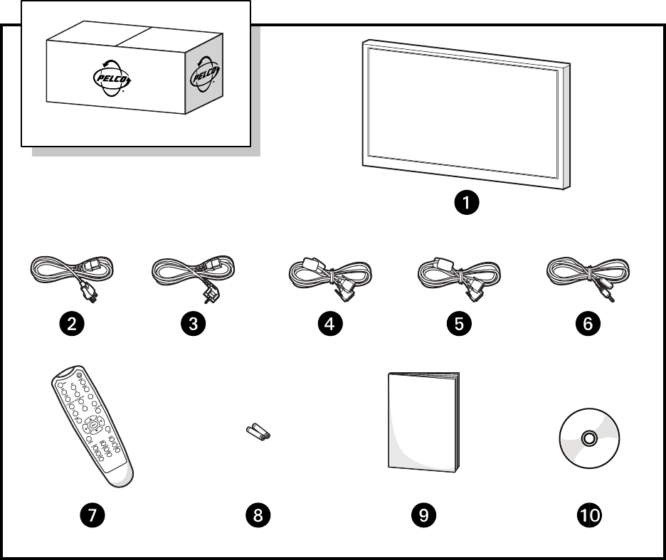
PACKAGE CONTENTS
Figure 1. Package Contents
USER-SUPPLIED PARTS
Only one DVI cable and one VGA cable is supplied by Pelco. Additional video (RS-232/RS-485), VGA, or DVI cables are required to configure video
walls using multiple monitors. Refer to Video Wall on page 19 to determine the needs for your particular installation.
ì42/46/55-inch FHD Monitor (1 ea.) rInfrared Extender (1 ea.)
îUSA Standard Power Cord (1 ea.) sRemote Control (1 ea.)
ïEuropean Standard Power Cord (1
ea.)
tAAA Batteries (2 ea.)
ñDVI Cable (1 ea.) uQuick Start Guide (1 ea.)
óVGA Cable with 15-pin D-Sub
Connection (1 ea.)
~í Resource Disc (1 ea.)
10 C2988M-A (6/11)
INDICATOR LIGHTS, CONTROLS, AND CONNECTIONS
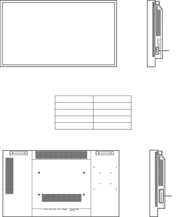
FRONT PANEL
Figure 2. Front Panel and Indicator Lights
CONTROL PANEL
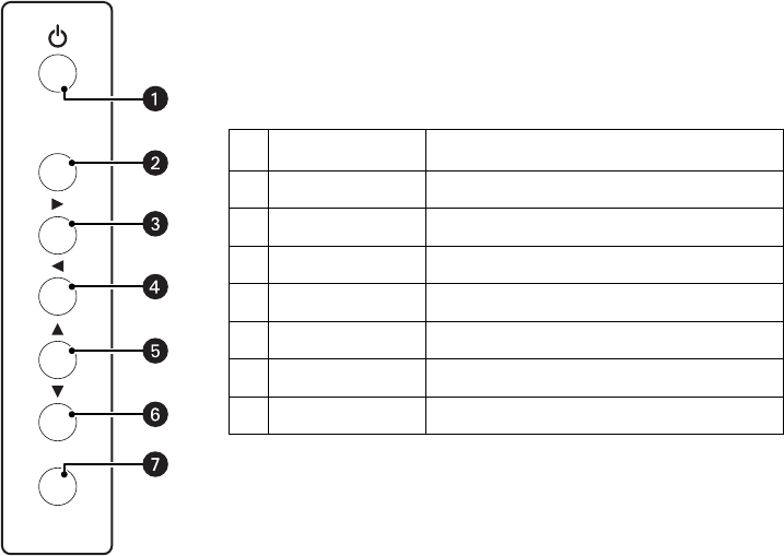
Figure 3. Control Panel and OSD Keypad
Table A. Light Indicators
Indicator Function
Green Normal operation
Blinking orange No signal
Orange Power saving mode
Not lit Power/AC off
INDICATOR
LIGHTS
OSD
KEYPAD
C2988M-A (6/11) 11
ON-SCREEN DISPLAY (OSD) KEYPAD FUNCTION LIST
Figure 4. OSD Keypad and Functions
MENU/EXIT
SOURCE
Key Description
ìPower Power Switch; power ON/OFF
îSource Source selection; activate selection
ïXMenu right/value increasing
ñWMenu left/value decreasing
óSMenu up
rTMenu down
sMenu/Exit OSD control menu button
12 C2988M-A (6/11)
CONNECTION PANEL
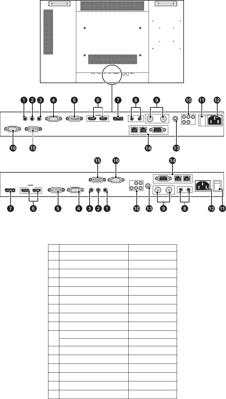
Figure 5. Connection Panel
Table B. Connection Panel
Name Connector
ìLine out Mini jack
îIR extender Mini jack
ïPC audio in Mini jack
ñVGA (PC) input 15-pin, D-sub
óDVI-D input 24 pin, D-sub
rHDMI input (input only)
sDisplayPort™(input only)
tAudio for S-Video/video input RCA W/R
uVideo input/output BNC
~í Y-Pb-Pr (Y-Cb-Cr) input RCA G/B/R
Audio for component input RCA W/R
~â Main power switch —
~ä Power cord input AC input
~ã S-Video input 4-pin, mini-DIN
~å RS-232C input 9-pin, D-sub/RJ-485
~ç DVI-D output 24-pin, D-sub
~é VGA (PC) output 15-pin, D-sub
HIGH-DEFINITION MULTIMEDIA INTERFACE
PMCL542NB
HIGH-DEFINITION MULTIMEDIA INTERFACE
PMCL546NB/PMCL555NB

C2988M-A (6/11) 13
Installation
SETUP
NOTES:
• Before connecting, turn off the monitor and any connected source equipment. After making all connections, turn on the monitor before
turning on other devices.
• When connecting a computer, be sure that the computer is the last device turned on, after all connections are made.
• Read the operation manuals of the video source equipment before making connections.
UNPACKING
The PMCL500 Series NB monitor is packed inside a box carton. Additional packing material has been placed within the carton to protect the
monitor during transport.
1. Before unpacking your monitor, prepare a stable, level, and clean surface near a wall outlet.
2. Set the monitor box in an upright position and pull out the white carton locks.
3. Lift up the top cover of the carton.
4. Remove the electrostatic discharge (ESD) bag before removing the display from the bottom tray carton.
CONNECTING VIDEO SOURCE EQUIPMENT
Video source equipment can be connected to any of the following interfaces:
• High Definition Multimedia Interface (HDMI)
• Component (Y, Pb, Pr)
•S-Video
• Composite (AV)
• HD-15 for VGA
•BNC
•DVI
• DisplayPort
CONNECTING THE POWER CORD
Connect the supplied power cord to the AC socket on the side of the monitor.
CONNECTING THE INFRARED (IR) EXTENDER
1. Connect the IR extender (supplied) to the IR extender jack.
2. Attach the extender to a bezel on the front of the monitor.
NOTE: The IR extender must be connected properly and affixed to one of the front bezels on the monitor for the remote control to operate effectively.
CONNECTING TO VIDEO EQUIPMENT
Use component (Y, Pb, Pr), S-Video, or composite (AV) cable when connecting to video equipment.
CONNECTING TO VIDEO SOURCES
It is recommended that you use HDMI cable when connecting to video sources that use HDMI output.
CONNECTING TO A COMPUTER
1. Connect the monitor to the computer using a high definition 15-pin VGA/DVI cable (supplied).
2. Secure the cable connectors by tightening the screws on both sides of the connector.

14 C2988M-A (6/11)
Operation
This section describes basic operating instructions for the PMCL500 Series NB monitors. Be sure that you have connected the required external
source equipment to the monitor before following these procedures.
GENERAL INFORMATION
The default language for the OSD is English. To change the OSD language, refer to the On-Screen Display (OSD) Menus on page 16.
CONNECTING THE POWER CABLE
1. Connect the power cord to the power cord connector on the side of the monitor.
2. Connect the power cord to an AC power source.
3. Press the main power switch on the bottom of the monitor to the (|) position.
4. Press the power switch on the control panel or on the remote control to turn on (|) or turn off (○) power to the monitor.
TURNING POWER ON
Once the power switch is set to the on position (refer to Connecting the Power Cable), press the power button located on the control panel or on
the remote control. It takes several seconds for the monitor to warm up after the power is turned on.
SELECTING INPUT SOURCE
To select the Input Source for the monitor, press the SOURCE button on the control panel or press the desired source key on the control panel or
on the remote control; pressing the AUTO key on the remote control will cycle to the next active source input.
TURNING POWER OFF
Press the power button located on the control panel or on the remote control.
C2988M-A (6/11) 15
USING THE MENU SCREEN
The image and display settings can be adjusted through the menu as listed on the control panel or by using the remote control.
REMOTE CONTROL
Locking and Unlocking the Remote Key and Keypad
Lock: Press Enter, Enter, Exit, Exit, Enter, and Exit on the controller by sequence and all keys (including remote and keypad) will be locked, except
Enter and Exit.
Unlock: Press Enter, Enter, Exit, Exit, Enter and Exit on the controller by sequence again and all keys will be unlocked.
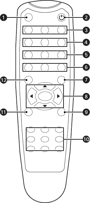
Figure 6. Remote Control Functions
ìINFO: Provides source and resolution information.
îPOWER: Turns the monitor on and off.
ïVGA: Selects the PC RGB source.
DVI: Selects the PC DVI source.
HDMI 1: Selects the HDMI source 1.
ñCOMP: Selects the component source.
AV (VIDEO): Selects the composite video source.
HDMI 2: Selects the HDMI source 2.
óP POSITION: Selects the PIP position.
DISPLAY PORT: Selects the DisplayPort source.
rPIP: Turns the PIP feature on and off.
S-V: Selects the S-Video source.
sP-SOURCE: Selects the secondary subsource.
tMENU: Displays the monitor’s on-screen menu system. When the menu
system is displayed, pressing this button will select the previous submenu.
S,W,X,T: Navigates through submenus and settings.
uEXIT: Closes the menu system.
~í SCALING: Toggles between different aspect ratios (Full Screen, Native, Letter
Box, and Pillar Box)
FREEZE: Freezes the current source image.
MUTE: Turns off the sound.
BRIGHT: Adjusts the brightness.
CONTRAST: Adjusts the contrast.
AUTO: Adjusts the VGA source automatically.
SOURCE: Allows selection of the different sources.
VOLUME-: Decreases the sound.
VOLUME+: Increases the sound.
~â ENTER: Selects highlighted menu choices.
~ä SWAP: Swaps the main source and subsource picture.
INFO
VGA DVI HDMI1
COMP
P-POSITION
PIP
SWAP P-SOURCE
MENU
ENTER
SCALING FREEZE MUTE
BRIGHT CONTRAST AUTO
SOURCE VOLUME- VOLUME+
EXIT
DISPLAYPORT
S-V
AV HDMI2

16 C2988M-A (6/11)
ON-SCREEN DISPLAY (OSD) MENUS
IMAGE SETTINGS
The following menus are used for making common image adjustments. To select the Image Settings menu options and ranges, press the right
and left arrows◀or ▶on the remote control or the control panel, and then press ENTER.
The following table lists the image settings, menu options/ranges, and the default settings.
Table C. Image Settings
Settings Menu Options/Ranges Default
Scheme User, Vivid, Cinema, Game, and Sport User
Brightness 0 to 100 50
Contrast 0 to 100 50
Sharpness 0 to 24 12
Saturation (Video Mode
only)
0 to 100 50
Hue (Video Mode only) 0 to 100 50
Backlight 0 to 100 80
Gamma Off or 2.2 2.2
Color Temperature User, 5000ºK, 6500ºK, 7500ºK, and 9300ºK 9300ºK
Red Gain* 128 to 384 256
Green Gain* 128 to 384 256
Blue Gain* 128 to 384 256
Red Offset* –50 to 50 0 (zero)
Green Offset* –50 to 50 0 (zero)
Blue Offset* –50 to 50 0 (zero)
*The color temperature must be set to “User” to adjust this setting.

C2988M-A (6/11) 17
DISPLAY SETTINGS
This menu is used for common source adjustments. To select the Display Settings menu options and ranges, press the right and left
arrows◀or ▶on the remote control or the control panel, and then press ENTER.
The following table lists the display settings, menu options/ranges, and the default settings.
NOTES:
• The maximum number of connecting devices for tiling mode is DVI = 9, VGA = 4, and Video = 4.
• The maximum cable length between displays for tiling mode is 3 meters.
Table D. Display Settings
MAIN
Settings Menu Options/Ranges Default
Aspect Ratio Full screen, Pillar Box, Letter Box, and
Native
Full Screen
Zoom 0 to 10 0
Auto Scan On, Off On
Select Source VGA, HDMI1, HDMI2, DVI, DisplayPort,
S-Video, Video, and Component
VGA
PIP
PIP Mode Off, Large PIP, Medium PIP, Small PIP, and
Side-by-Side
Off
PIP Position Bottom-Right, Top-Left, Top-Right, and
Bottom-Left
Bottom-Right
Aspect Ratio Full Screen, Pillar Box, and Letter Box Full Screen
Side-by-Side Scale Zoom In, Zoom Out, Main, PIP, Default,
and Return
—
Auto Scan On, Off On
Select Source HDMI1, HDMI2, DVI, DisplayPort,
Component, S-Video, and Video
VGA for Main, Video for PIP
18 C2988M-A (6/11)
AUDIO SETTINGS
This menu is used for adjusting volume settings. To select the Audio Settings menu options and ranges, press the right and left
arrows◀or ▶on the remote control or the control panel, and then press ENTER.
The following table lists the audio settings, menu options/ranges, and the default settings.
BASIC SETTINGS
This menu is used to make initial setup adjustments to the OSD menu and other on-screen messages. To select the Basic Settings menu options
and ranges, press the right and left arrows◀or ▶on the remote control or the control panel, and then press ENTER.
The following table lists the basic settings, menu options/ranges, and the default settings.
REAL TIME CLOCK
This submenu is used to make adjustments to the monitor’s internal clock. To select the Real Time Clock submenu options and ranges, press the
right and left arrows◀or ▶on the remote control or the control panel, and then press ENTER.
The following table lists the Real Time Clock settings, submenu options/ranges, and the default settings in Year/Month/Date/Hour:Minutes
format.
Refer to Resolution Tables on page 26 for more information.
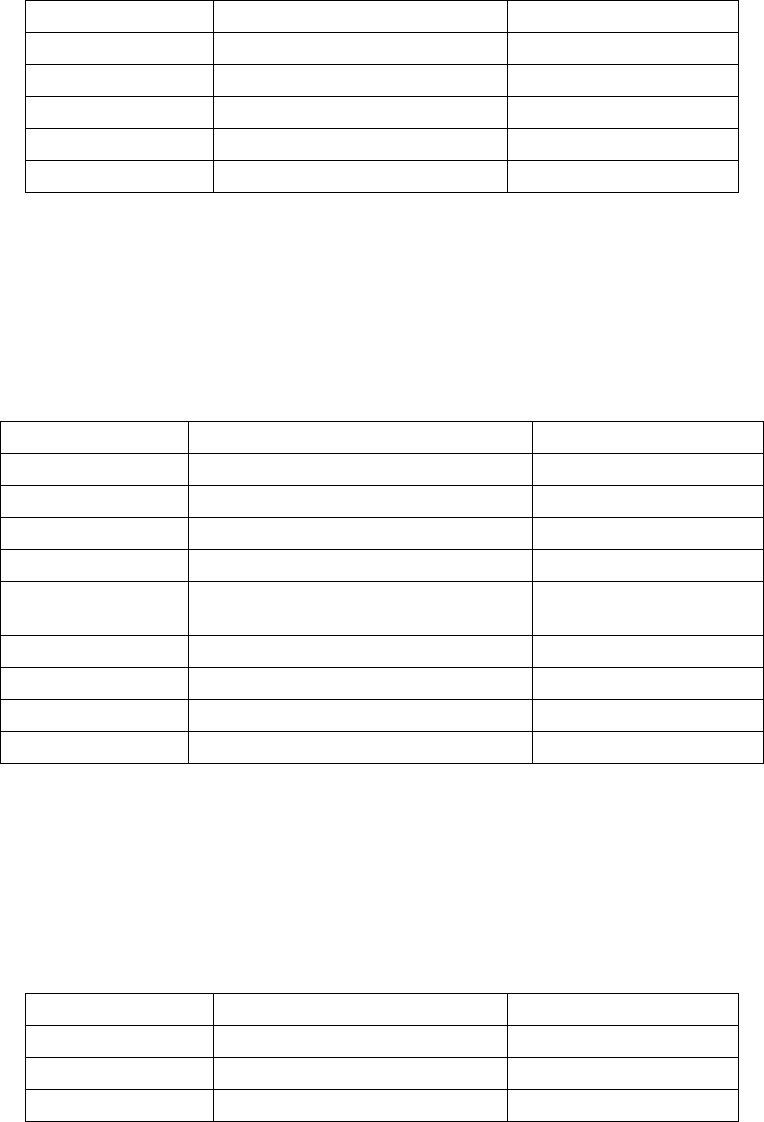
Table E. Audio Settings
Settings Menu Options/Ranges Default
Volume 0 to 100 50
Bass 0 to 20 10
Treble 0 to 20 10
Balance 0 to 20 10
HDMI Audio Input HDMI, PC HDMI
Table F. Basic Settings
Settings Menu Options/Ranges Default
OSD Transparent 0 to 100 0
OSD Location Up, Down, Left, and Right —
OSD Zoom On, Off Off
OSD Rotation Landscape, Portrait Landscape
OSD Language English, Simplified Chinese, French, German,
Italian, Portuguese, Russian, and Spanish
English
OSD Timeout 5 to 120 30
Sleep Timer Off, 15, 30, 60, 90, and 120 minutes Off
Power LED On, Off On
Real Time Clock (press X to display the Real Time Clock submenu) —
Table G. Real Time Clock Settings
Settings Menu Options/Ranges Default
Real Time (date and time) —
Alarm Power On Disable, Enable Disable
Alarm Power Off Disable, Enable Disable
C2988M-A (6/11) 19
ADVANCED SETTINGS
This menu is used to make advanced settings adjustments. To select the Advanced Settings menu options and ranges, press the right and left
arrows◀or ▶on the remote control or the control panel, and then press ENTER.
The following table lists the advanced settings, menu options/ranges, and the default settings for video wall configuration.
VIDEO WALL
This submenu is used to make adjustments to the video wall display. To select the Video Wall submenu options and ranges, press the right and
left arrows Wor X or the up and down arrows Sor T on the remote control or control panel, and then press ENTER.
CONNECTION TYPES
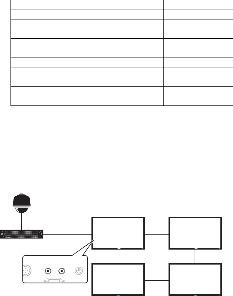
Video walls can be configured in a 2 x 2 grid or a 3 x 3 grid, using the following three connection types.
Video (BNC type): Supports a maximum video wall grid of 2 x 2 monitors.
Figure 7. Video (BNC Type) Connection
Table H. Advanced Settings
Settings Menu Options/Ranges Default
Auto Adjustment No, Yes No
Image Position Up, Down, Left, and Right —
Phase 0 to 63 (only VGA mode) —
Clocks 0 to 100 (only VGA mode) —
VGA ADC Settings Default, User Default
Flesh Tone Off, Low, Medium, and High (only video mode) Off
IRFM On, Off Off
Baud Rate 115200, 38400, 19200, and 9600 115200
Video Wall (press X to display the Video Wall submenu) —
Factory Reset No, Yes No
VIDEO
IN
VIDEO
OUT
VIDEO
VIDEO
(1,1) (2,1)
(1,2) (2,2)
VIDEO
DVR
CAMERA
VIDEO
20 C2988M-A (6/11)
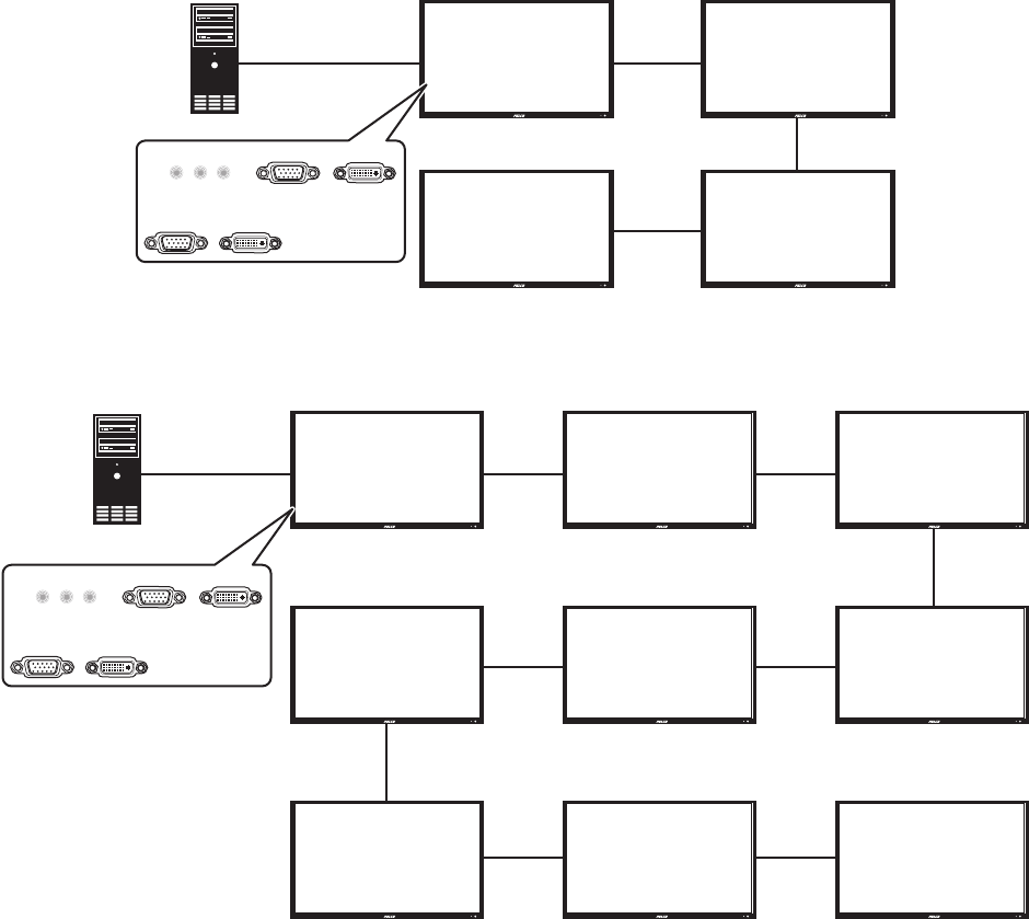
VGA: Supports a maximum video wall grid of 2 x 2 monitors.
Figure 8. VGA Connection
DVI: Supports a maximum video wall grid of 3 x 3 monitors.
Figure 9. DVI Connection
VIDEO WALL PARAMETERS
The following information describes the settings, and lists the submenu options/ranges and default settings for defining your video wall
parameters:
Monitor ID: Allows the user to set an individual monitor ID for each monitor. To control a monitor or multiple monitors that are daisy-chained by
RS-232, each monitor must have a unique monitor ID. Numbers 1 to 25 are available to be used as monitor IDs. It is recommended to number
each monitor in an RS-232 daisy chain sequentially starting with number 1.
NOTES:
• DVI input can support up to a 3 x 3 grid and loop through directly.
• VGA and video input can support up to a 2 x 2 grid and loop through directly.
Video Wall: Enables or disables the video wall. Select Yes to enable the video wall. The default setting is No, which disables the video wall
feature.
DVI Indemnity: Compensates manually for image degradation caused by daisy-chaining too many monitors using DVI cables. It is recommended
that you select the On option for the 7th, 8th, and 9th monitors in a DVI daisy-chain. For monitors 1 to 6, it is recommended that you select the
default Off option.
VGA
VGA
(1,1) (2,1)
(1,2) (2,2)
VGA
VGA
VGA IN DVI IN
VGA OUT DVI OUT
(1,1) (2,1) (3,1)
(1,2) (2,2) (3,2)
(1,3) (2,3) (3,3)
DVI DVI DVI
DVI DVI
DVI
DVI
DVI
DVI
VGA IN DVI IN
VGA OUT DVI OUT
C2988M-A (6/11) 21
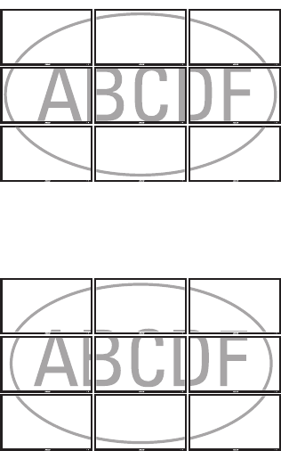
Frame: Turns on or off the frame compensation.
Select Yes to turn on frame compensation. Part of the signal will be hidden by the monitors’ bezels.
Figure 10. Video Wall Display with Frame On
Select the default No setting to turn off frame compensation. The entire signal will be displayed.
Figure 11. Video Wall Display with Frame Off
Matrix X: The number of monitors arranged horizontally. Matrix X can range from 1 to 3 monitors by connecting with a DVI source, or 1 to 2
monitors by connecting with a VGA or video source.
Matrix Y: The number of monitors arranged vertically. Matrix Y can range from 1 to 3 monitors by connecting with a DVI source, or 1 to 2
monitors by connecting with a VGA or video source.
Division X: Selects the horizontal position in each row for a specific monitor.
Division Y: Selects the vertical position in each column for a specific monitor.
22 C2988M-A (6/11)
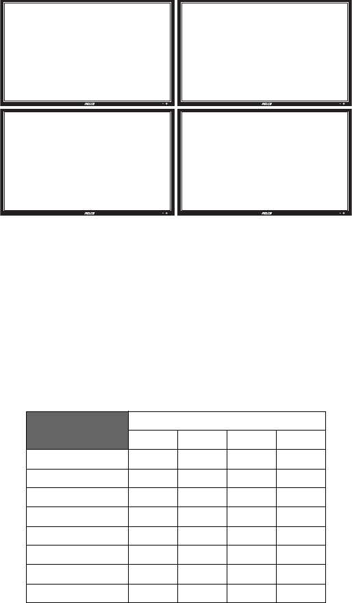
2 X 2 VIDEO WALL GRID
Four monitors are used to construct a 2 x 2 video wall grid.
Figure 12. 2 x 2 Video Wall Grid
To configure a 2 x 2 video wall grid:
1. Determine the input signal type and connect the video signal (refer to Connection Types on page 19).
2. Connect an RS-232 cable (not supplied) to the first monitor (1,1) to enable the remote control function.
3. Connect the remaining three monitors using RS-485 cables (not supplied). Refer to RS-232 Control on page 24 for more information.
4. Set up the video wall parameters according to the following information.
.
Table I. 2 x 2 Video Wall Parameters
Monitor Position
1,1 2,1 2,2 1,2
Monitor ID 1234
Video Wall Yes Yes Yes Yes
DVI Indemnity Off Off Off Off
Frame Yes Yes Yes Yes
Matrix X 2222
Matrix Y 2222
Division X 1221
Division Y 1122
(1,1) (2,1)
(1,2) (2,2)
C2988M-A (6/11) 23
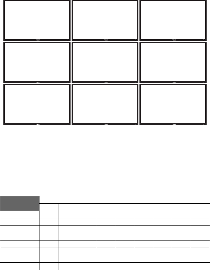
3 X 3 VIDEO WALL GRID
Nine monitors are used to construct a 3 x 3 video wall grid.
Figure 13. 3 x 3 Video Wall Grid
To configure a 3 x 3 video wall grid:
1. Connect all monitors using DVI cables. Refer to Connection Types on page 19 for the monitor connection sequence.
NOTE: Only one DVI cable is supplied by Pelco. Additional user-supplied cables are required to configure video walls using multiple
monitors.
2. Set up the video wall parameters according to the following information:
Table J. 3 x 3 Video Wall Parameters
Monitor Position
1,1 2,1 3,1 3,2 2,2 1,2 1,3 2,3 3,3
Monitor ID 123456789
Video Wall Yes Yes Yes Yes Yes Yes Yes Yes Yes
DVI Indemnity Off Off Off Off Off Off On On On
Frame Yes Yes Yes Yes Yes Yes Yes Yes Yes
Matrix X 333333333
Matrix Y 333333333
Division X 123321123
Division Y 111222333
(1,1) (2,1)
(1,2) (2,2)
(3,1)
(3,2)
(1,3) (2,3) (3,3)
24 C2988M-A (6/11)
OSD MENU FOR VIDEO WALL SETUP
1. Press Menu on the remote control or control panel.
2. Press Up or Down to navigate to the Advanced Settings screen.
3. Press Right to enter the Advanced Settings menu.
4. Press Up or Down to navigate to the Video Wall submenu.
5. Press Right to access the Video Wall settings menu; the default setting is No.
6. Navigate to the Video Wall option, and press Right to change the Video Wall setting from No to Yes. The video wall menu displays.
7. Configure the video wall. Refer to Video Wall Parameters on page 20 for more information.
8. Press Menu on the remote control or control panel to exit.
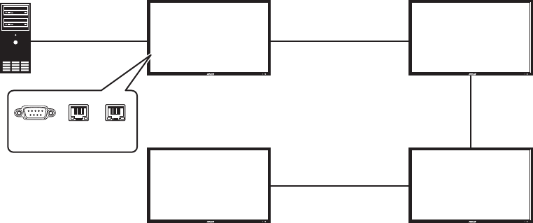
RS-232 CONTROL
Connect an RS-232 terminal or a personal computer to the video wall using an RS-232 cable (not supplied) from the controlling device to the first
monitor. Use three RS-485 cables (not supplied) to connect the remaining three monitors.
Figure 14. RS-232 Connection
NOTES:
• To function correctly, any monitors using an RS-485 OUT connection can only be connected to another monitor of the same series model.
• RS-232 connections only support 9-pin serial straight cables; crossover or null modem cables are not supported.
• RS-485 connections only support Cat5 straight cables; crossover cables are not supported.
For more information on creating a video wall, contact Pelco Product Support at 1-800-289-9100 (USA and Canada) or +1-559-292-1981
(international) for assistance. Be sure to have the serial number available when calling.
(1,1) (2,1)
(1,2) (2,2)
RS-485 IN RS-485 OUT
RS-485 OUT RS-485 IN
RS-232 IN
RS-485 OUT
RS-485 IN
RS-232 RS-485
IN
RS-485
OUT
C2988M-A (6/11) 25
SYSTEM STATUS MENU
This read-only menu provides information on the active sources and the latest firmware version.
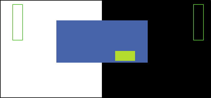
USER ANALOG TO DIGITAL CONVERTER (ADC) CALIBRATION
When using VGA as the signal source, you must choose your user ADC calibration.
1. Go to Advanced Settings in the OSD menu.
2. Select VGA ADC Settings, and then choose ADC Calibration.
The “Ready to run ADC Calibration” message appears to verify that the image is displaying properly before ADC calibration begins.
NOTES:
• The images in the green Region boxes (left and right) have to be white and black to run the calibration accurately. The black and white
images can be made using software such as Microsoft® PowerPoint®.
• The white in the left Region box has to be the brightest white; the black in the right Region box has to be the darkest black.
Figure 15. User ADC Calibration
3. After the proper image has been verified, click “Yes” to begin ADC calibration. The User ADC Calibration Wait message appears.
After the calibration is complete, a User ADC Calibration message will indicate if the process has successfully completed or failed.
REGION 2 (BLACK)REGION 1 (WHITE)
Important Note:
Ready to run ADC Calibration?
1. The “Region 1” must be all white.
2. The “Region 2” must be all black.
Yes No

26 C2988M-A (6/11)
RESOLUTION TABLES
Table K. Composite/Component/S-Video Mode
Mode Resolution Vertical Frequency (Hz)
SDTV 480i (NTSC)* 720 x 480 30
SDTV 576i (PAL)†720 x 576 25
EDTV 480p‡720 x 480 60
EDTV 576p‡720 x 576 50
HDTV 720p‡1280 x 720 50/60
HDTV 1080i‡1920 x 1080 50/60
HDTV 1080p‡1920 x 1080 50/60
*Supported 480i at 60 Hz (YPbPr)
†Supported 576i at 50 Hz (YPbPr)
‡Component only
Table L. DisplayPort/DVI/HDMI/VGA Mode
Mode Resolution Vertical Frequency (Hz)
VGA 640 x 480 60/72/75/85
SVGA 800 x 600 50/60/72/75/85
XGA 1024 x 768 60/70/75/85
WXGA 1280 x 768 60/85
WXGA 1280 x 800 60
SXGA 1280 x 1024 60/75/85
WXGA 1360 x 768 60
SXGA+ 1400 x 1050 60
WSXGA 1440 x 900 60
WSXGA+ 1680 x 1050 60
UXGA 1600 x 1200 60
EDTV 480P 720 x 480 60
EDTV 576P 720 x 576 50
HDTV 720P 1280 x 720 50/60/75
HDTV 1080i 1920 x 1080 50/60
HDTV 1080p 1920 x 1080 50/60
C2988M-A (6/11) 27
Troubleshooting
If the following instructions fail to solve your problem, contact Pelco Product Support at 1-800-289-9100 (USA and Canada) or +1-559-292-1981
(international) for assistance. Be sure to have the serial number available when calling.
Do not try to repair the unit yourself. Opening it immediately voids the warranty. Leave maintenance and repairs to qualified technical personnel
only. Refer to the Product Warranty and Return Information located on the inside back page of this document.
WARNING: To reduce the risk of electrical shock, do not remove the cover or back of the monitor. There are no user-serviceable parts
inside.
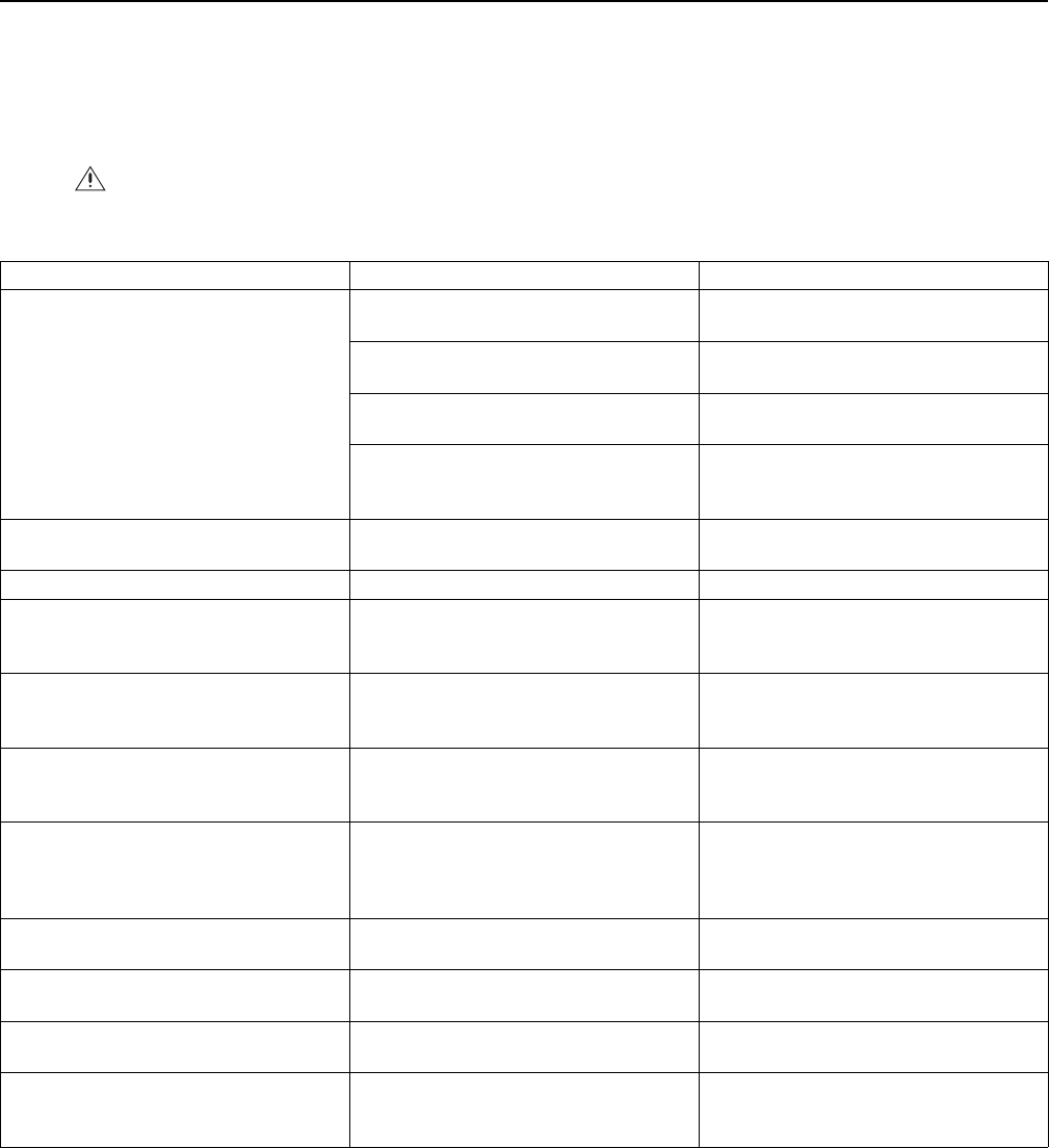
Table M. Troubleshooting
Problem Possible Cause Suggested Solution
No image appears. The power cord is not connected properly to the
power outlet.
Ensure that the power cord is connected properly
to the power outlet.
The main power switch is not in the “|” position. Ensure that the main power switch in the “|”
position.
Is the power indicator amber? If it is, the ON
button might not have been pressed.
Press the ON button on the remote control or
control panel.
The S-Video input and the AV2 input might be
connected at the same time.
Ensure that the S-Video input and the AV2 input
are not connected at the same time. If they are,
remove either the S-Video input or the AV2 input.
The screen color is unstable or monochrome. The the source cable might not be properly
connected.
Check the source cable connection to ensure a
proper fit.
There are black dots on the screen. The screen surface might not be clean. Wipe the screen surface with a clean, soft cloth.
The screen is partially blurred. Nearby objects might be generating magnetic
fields. Such objects include speakers, steel
structures, and high-voltage lines.
Remove any objects that might be generating
magnetic fields from the immediate vicinity and
use the OSD menu to adjust the screen.
The screen is flickering. Magnetic material might be interfering with the
image.
Move any highly magnetic material away from the
monitor, and then adjust the graphic interface (PC
Mode) within the allotted frequency parameters.
The image is dark. The backlight and brightness settings might not
be correct.
Adjust the backlight and brightness. It takes
several seconds for the monitor to warm up after
the power is turned on.
The image appears to be ghosting. The source equipment connection cables might be
too long.
Ensure the source equipment connection cables
are shorter than 15 meters (50 ft). If additional
length is required, contact your authorized dealer
for a signal amplifier (not supplied).
The image size is incorrect. The image format might not be set correctly. Adjust the image format to the desired image
size.
White does not look bright enough. The color temperature might need adjusting, or
the “User” settings might not be optimal.
Adjust the color temperature or change the
“User” settings to your preferred settings.
The image is not centered. The image format might need to be adjusted. Adjust the image format to your desired image
size.
The remote control does not work. The IR Extender might not be properly connected. Ensure that the IR Extender is properly connected
and attached to a bezel on the front of the
monitor.

28 C2988M-A (6/11)
Specifications
GENERAL
Viewing Area
PMCL542NB 950.2 x 523.3 mm
PMCL546NB 1018.1 x 572.7 mm
PMCL555NB 1209.6 x 684.0 mm
Number of Pixels 1920 (H) x 1080 (V)
Pixel Pitch
PMCL542NB 0.485 x 0.485 mm
PMCL546NB 0.530 x 0.530 mm
PMCL555NB 0.630 x 0.630 mm
Brightness 700 cd/m2 (typical)
Contrast Ratio
PMCL542NB 3500:1
PMCL546NB 3000:1
PMCL555NB 5000:1
Backlight Type CCFL
Refresh Rate 60 Hz
Viewing Angle (H/V) 178°/178°
Response Time* 8 ms
Native Resolution 1920 x 1080 at 60 Hz
Optimum Resolution (RGB Mode)
VGA 640 x 480 at 56/60/72/75/85 Hz
SVGA 800 x 600 at 60/70/75/85 Hz
XGA 1024 x 768 at 60/75/85 Hz
SXGA 1280 x 1024 at 60/75/85 Hz
WXGA 1360 x 768 at 60 Hz
UXGA 1600 x 1200 at 60 Hz
SDTV (480i/576i/480p/576p)†720 x 480 at 60 Hz
720 x 576 at 50 Hz
HDTV (720p/1080i/1080p) 1280 x 720 at 50/60 Hz
1920 x 1080p at 50/60 Hz
1920 x 1080i at 50/60 Hz
Panel Aspect Ratio 16:9
Video Formats 480p, 576p, 720p, 1080i, 1080p
Panel Life 50,000 plus hours
Display Colors
PMCL542NB 16.7 million
PMCL546NB, PMCL555NB 1.07 billion
PIP (Picture-In-Picture) Selectable, sizeable, swappable, moveable
Speakers 2, internal (10 W, 4 ohms x 2)
Front Panel Controls Menu, source, down/up, vol -/+, power
Indicators LED (power on/off)
*Response time is measured by one monitor with stable signal and without extra IR or keypad control.
†Supported 480i at 60 Hz (YPbPr); supported 576i at 50 Hz (YPbPr)
C2988M-A (6/11) 29
ELECTRICAL/VIDEO
Power Consumption
PMCL542NB 261 W
PMCL546NB 251 W
PCML555NB 356 W
Input Voltage 100 to 240 VAC, 50/60 Hz
Video Inputs 1 BNC, looping; 1 S-Video; 1 DisplayPort; 2 HDMI; 1 RGB in; 1 RGB out; 1 DVI in; 1 DVI out; 1 component
Horizontal Frequency 31 KHz to 91 KHz
Vertical Frequency 56 Hz to 85 Hz
Sync Format NTSC/PAL
AUDIO
Audio Inputs 2, audio, RCA jack; 1 PC Audio in; 1 Line out
Input Voltage 2.5 Vp-p
Channels 2
Input Impedance 40 kohms
Power Output 10 W
Distortion <10%
Bandwidth 380 to 20kHz
Adjustment Linear
ENVIRONMENTAL
Operating Temperature 0° to 40°C (32° to 104°F)
Storage Temperature –20° to 60°C (–4° to 140°F)
Operating Humidity 20% to 80%, noncondensing
Storage Humidity 10% to 90%, noncondensing
PHYSICAL
Dimensions (without stand)
PMCL542NB 12.6 x 95.9 x 55.0 cm
(4.9" D x 37.8" W x 21.7" H)
PMCL546NB 13.2 x 105.0 x 60.3 cm
(5.2" D x 41.7" W x 23.7" H)
PMCL555NB 13.7 x 124.8 x 71.9 cm
(5.4" D x 49.1" W x 28.3" H)
Unit Weight
PMCL542NB 27 kb (59 lb)
PMCL546NB 29 kg (64 lb)
PMCL555NB 45 kg (99 lb)
Wall Mount
PMCL542NB VESA® 400 x 200 mm (15.7" x 7.9")
PMCL546NB VESA 400 x 200 mm (15.7" x 7.9")
PMCL555NB VESA 600 x 400 mm (23.6" x 15.7")
The materials used in the manufacture of this document and its components are compliant to the requirements of Directive 2002/95/EC.
This equipment contains electrical or electronic components that must be recycled properly to comply with Directive 2002/96/EC of the European Union
regarding the disposal of waste electrical and electronic equipment (WEEE). Contact your local dealer for procedures for recycling this equipment.
PRODUCT WARRANTY AND RETURN INFORMATION
WARRANTY
Pelco will repair or replace, without charge, any merchandise proved defective in
material or workmanship for a period of one year after the date of shipment.
Exceptions to this warranty are as noted below:
• Five years:
– Fiber optic products
– Unshielded Twisted Pair (UTP) transmission products
– CC3701H-2, CC3701H-2X, CC3751H-2, CC3651H-2X, MC3651H-2, and
MC3651H-2X camera models
• Three years:
– Fixed network cameras and network dome cameras with Sarix® technology
– Sarix thermal imaging products (TI and ESTI Series)
– Fixed camera models (CCC1390H Series, C10DN Series, C10CH Series, and
IP3701H Series)
– EH1500 Series enclosures
– Spectra® IV products (including Spectra IV IP)
– Spectra HD dome products
– Camclosure® Series (IS, ICS, IP) integrated camera systems
– DX Series video recorders (except DX9000 Series which is covered for a
period of one year), DVR5100 Series digital video recorders, Digital Sentry®
Series hardware products, DVX Series digital video recorders, and NVR300
Series network video recorders
– Endura® Series distributed network-based video products
– Genex® Series products (multiplexers, server, and keyboard)
– PMCL200/300/400 Series LCD monitors
– PMCL5xxF Series and PMCL5xxNB Series LCD monitors
• Two years:
– Standard varifocal, fixed focal, and motorized zoom lenses
– DF5/DF8 Series fixed dome products
– Legacy® Series integrated positioning systems
– Spectra III™, Spectra Mini, Spectra Mini IP, Esprit®, ExSite®, ExSite IP, and
PS20 scanners, including when used in continuous motion applications
– Esprit Ti and TI2500 Series thermal imaging products
– Esprit and WW5700 Series window wiper (excluding wiper blades)
– CM6700/CM6800/CM9700 Series matrix
– Digital Light Processing (DLP®) displays (except lamp and color wheel). The
lamp and color wheel will be covered for a period of 90 days. The air filter is
not covered under warranty.
•Six months:
– All pan and tilts, scanners, or preset lenses used in continuous motion
applications (preset scan, tour, and auto scan modes)
Pelco will warrant all replacement parts and repairs for 90 days from the date of
Pelco shipment. All goods requiring warranty repair shall be sent freight prepaid
to a Pelco designated location. Repairs made necessary by reason of misuse,
alteration, normal wear, or accident are not covered under this warranty.
Pelco assumes no risk and shall be subject to no liability for damages or loss
resulting from the specific use or application made of the Products. Pelco’s liability
for any claim, whether based on breach of contract, negligence, infringement of
any rights of any party or product liability, relating to the Products shall not exceed
the price paid by the Dealer to Pelco for such Products. In no event will Pelco be
liable for any special, incidental, or consequential damages (including loss of use,
loss of profit, and claims of third parties) however caused, whether by the
negligence of Pelco or otherwise.
The above warranty provides the Dealer with specific legal rights. The Dealer may
also have additional rights, which are subject to variation from state to state.
If a warranty repair is required, the Dealer must contact Pelco at (800) 289-9100 or
(559) 292-1981 to obtain a Repair Authorization number (RA), and provide the
following information:
1. Model and serial number
2. Date of shipment, P.O. number, sales order number, or Pelco invoice number
3. Details of the defect or problem
If there is a dispute regarding the warranty of a product that does not fall under
the warranty conditions stated above, please include a written explanation with
the product when returned.
Method of return shipment shall be the same or equal to the method by which the
item was received by Pelco.
RETURNS
To expedite parts returned for repair or credit, please call Pelco at (800) 289-9100
or (559) 292-1981 to obtain an authorization number (CA number if returned for
credit, and RA number if returned for repair) and designated return location.
All merchandise returned for credit may be subject to a 20 percent restocking and
refurbishing charge.
Goods returned for repair or credit should be clearly identified with the assigned
CA or RA number and freight should be prepaid. Revised 5-6-11
REVISION HISTORY
Manual # Date Comments
C2988M 3/11 Original version.
C2988M-A 6/11 Added Video Wall section.
Pelco, the Pelco logo, and other trademarks associated with Pelco products referred to in this publication are trademarks of Pelco, Inc. or its affiliates. © Copyright 2011, Pelco, Inc.
All other product names and services are the property of their respective companies. All rights reserved.
Product specifications and availability are subject to change without notice.