Pelco Endura Nsm5200 Series Users Manual Pelco_NSM5200_Series_Network_Storage_Manager_manual
NSM5200 to the manual 3146de99-a1c1-4e13-b01f-2bf43f9c07ee
2015-02-02
: Pelco Pelco-Endura-Nsm5200-Series-Nsm5200-Users-Manual-440548 pelco-endura-nsm5200-series-nsm5200-users-manual-440548 pelco pdf
Open the PDF directly: View PDF ![]() .
.
Page Count: 32
INSTALLATION
C3683M (3/09)
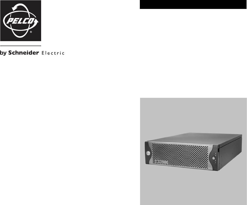
Network Storage Manager
Endura®
NSM5200 Series

C3683M (3/09) 3
Contents
Regulatory Notices . . . . . . . . . . . . . . . . . . . . . . . . . . . . . . . . . . . . . . . . . . . . . . . . . . . . . . . . . . . . . . . . . . . . . . . . . . . . . . . . . . . . . . . . . . . . . . . . . . . . 5
Video Quality Caution . . . . . . . . . . . . . . . . . . . . . . . . . . . . . . . . . . . . . . . . . . . . . . . . . . . . . . . . . . . . . . . . . . . . . . . . . . . . . . . . . . . . . . . . . . . . . . . . . . 5
Description. . . . . . . . . . . . . . . . . . . . . . . . . . . . . . . . . . . . . . . . . . . . . . . . . . . . . . . . . . . . . . . . . . . . . . . . . . . . . . . . . . . . . . . . . . . . . . . . . . . . . . . . . . . 6
Features . . . . . . . . . . . . . . . . . . . . . . . . . . . . . . . . . . . . . . . . . . . . . . . . . . . . . . . . . . . . . . . . . . . . . . . . . . . . . . . . . . . . . . . . . . . . . . . . . . . . . . . . 7
Models . . . . . . . . . . . . . . . . . . . . . . . . . . . . . . . . . . . . . . . . . . . . . . . . . . . . . . . . . . . . . . . . . . . . . . . . . . . . . . . . . . . . . . . . . . . . . . . . . . . . . . . . . 8
Optional Accessories . . . . . . . . . . . . . . . . . . . . . . . . . . . . . . . . . . . . . . . . . . . . . . . . . . . . . . . . . . . . . . . . . . . . . . . . . . . . . . . . . . . . . . . . . . . . . . 8
Before You Begin . . . . . . . . . . . . . . . . . . . . . . . . . . . . . . . . . . . . . . . . . . . . . . . . . . . . . . . . . . . . . . . . . . . . . . . . . . . . . . . . . . . . . . . . . . . . . . . . . . . . . . 9
Parts List . . . . . . . . . . . . . . . . . . . . . . . . . . . . . . . . . . . . . . . . . . . . . . . . . . . . . . . . . . . . . . . . . . . . . . . . . . . . . . . . . . . . . . . . . . . . . . . . . . . . . . . . 9
User-Supplied Parts . . . . . . . . . . . . . . . . . . . . . . . . . . . . . . . . . . . . . . . . . . . . . . . . . . . . . . . . . . . . . . . . . . . . . . . . . . . . . . . . . . . . . . . . . . . . . . 10
Package Contents . . . . . . . . . . . . . . . . . . . . . . . . . . . . . . . . . . . . . . . . . . . . . . . . . . . . . . . . . . . . . . . . . . . . . . . . . . . . . . . . . . . . . . . . . . . . . . . . 10
Product Serial Number Label Placement . . . . . . . . . . . . . . . . . . . . . . . . . . . . . . . . . . . . . . . . . . . . . . . . . . . . . . . . . . . . . . . . . . . . . . . . . . . . . . 12
Equipment Placement and Rack Mounting . . . . . . . . . . . . . . . . . . . . . . . . . . . . . . . . . . . . . . . . . . . . . . . . . . . . . . . . . . . . . . . . . . . . . . . . . . . . . . . . . 13
Desktop Installation . . . . . . . . . . . . . . . . . . . . . . . . . . . . . . . . . . . . . . . . . . . . . . . . . . . . . . . . . . . . . . . . . . . . . . . . . . . . . . . . . . . . . . . . . . . . . . 13
Rack Mounting . . . . . . . . . . . . . . . . . . . . . . . . . . . . . . . . . . . . . . . . . . . . . . . . . . . . . . . . . . . . . . . . . . . . . . . . . . . . . . . . . . . . . . . . . . . . . . . . . . 14
Hard Drive Array Installation . . . . . . . . . . . . . . . . . . . . . . . . . . . . . . . . . . . . . . . . . . . . . . . . . . . . . . . . . . . . . . . . . . . . . . . . . . . . . . . . . . . . . . . . . . . . 19
Installing Hard Drive Carriers . . . . . . . . . . . . . . . . . . . . . . . . . . . . . . . . . . . . . . . . . . . . . . . . . . . . . . . . . . . . . . . . . . . . . . . . . . . . . . . . . . . . . . . 19
Connections . . . . . . . . . . . . . . . . . . . . . . . . . . . . . . . . . . . . . . . . . . . . . . . . . . . . . . . . . . . . . . . . . . . . . . . . . . . . . . . . . . . . . . . . . . . . . . . . . . . . . . . . . 21
Connecting Power. . . . . . . . . . . . . . . . . . . . . . . . . . . . . . . . . . . . . . . . . . . . . . . . . . . . . . . . . . . . . . . . . . . . . . . . . . . . . . . . . . . . . . . . . . . . . . . . 21
Connecting to the Network. . . . . . . . . . . . . . . . . . . . . . . . . . . . . . . . . . . . . . . . . . . . . . . . . . . . . . . . . . . . . . . . . . . . . . . . . . . . . . . . . . . . . . . . . 22
Operation . . . . . . . . . . . . . . . . . . . . . . . . . . . . . . . . . . . . . . . . . . . . . . . . . . . . . . . . . . . . . . . . . . . . . . . . . . . . . . . . . . . . . . . . . . . . . . . . . . . . . . . . . . . 23
Front Panel Controls and Indicators . . . . . . . . . . . . . . . . . . . . . . . . . . . . . . . . . . . . . . . . . . . . . . . . . . . . . . . . . . . . . . . . . . . . . . . . . . . . . . . . . . 23
Unit Startup. . . . . . . . . . . . . . . . . . . . . . . . . . . . . . . . . . . . . . . . . . . . . . . . . . . . . . . . . . . . . . . . . . . . . . . . . . . . . . . . . . . . . . . . . . . . . . . . . . . . . 25
Unit Shutdown . . . . . . . . . . . . . . . . . . . . . . . . . . . . . . . . . . . . . . . . . . . . . . . . . . . . . . . . . . . . . . . . . . . . . . . . . . . . . . . . . . . . . . . . . . . . . . . . . . 25
Troubleshooting . . . . . . . . . . . . . . . . . . . . . . . . . . . . . . . . . . . . . . . . . . . . . . . . . . . . . . . . . . . . . . . . . . . . . . . . . . . . . . . . . . . . . . . . . . . . . . . . . . . . . . 26
NSM5200 . . . . . . . . . . . . . . . . . . . . . . . . . . . . . . . . . . . . . . . . . . . . . . . . . . . . . . . . . . . . . . . . . . . . . . . . . . . . . . . . . . . . . . . . . . . . . . . . . . . . . . 26
Power Supplies . . . . . . . . . . . . . . . . . . . . . . . . . . . . . . . . . . . . . . . . . . . . . . . . . . . . . . . . . . . . . . . . . . . . . . . . . . . . . . . . . . . . . . . . . . . . . . . . . . 26
Specifications . . . . . . . . . . . . . . . . . . . . . . . . . . . . . . . . . . . . . . . . . . . . . . . . . . . . . . . . . . . . . . . . . . . . . . . . . . . . . . . . . . . . . . . . . . . . . . . . . . . . . . . 27
Appendices . . . . . . . . . . . . . . . . . . . . . . . . . . . . . . . . . . . . . . . . . . . . . . . . . . . . . . . . . . . . . . . . . . . . . . . . . . . . . . . . . . . . . . . . . . . . . . . . . . . . . . . . . 29
Appendix A: Expanding Video Storage. . . . . . . . . . . . . . . . . . . . . . . . . . . . . . . . . . . . . . . . . . . . . . . . . . . . . . . . . . . . . . . . . . . . . . . . . . . . . . . . 29
Appendix B: Installing an Uninterruptible Power Supply (UPS) . . . . . . . . . . . . . . . . . . . . . . . . . . . . . . . . . . . . . . . . . . . . . . . . . . . . . . . . . . . . . 30

4C3683M (3/09)
List of Illustrations
1 Major Package Components. . . . . . . . . . . . . . . . . . . . . . . . . . . . . . . . . . . . . . . . . . . . . . . . . . . . . . . . . . . . . . . . . . . . . . . . . . . . . . . . . . . . . . . . 10
2 Accessory Pack . . . . . . . . . . . . . . . . . . . . . . . . . . . . . . . . . . . . . . . . . . . . . . . . . . . . . . . . . . . . . . . . . . . . . . . . . . . . . . . . . . . . . . . . . . . . . . . . . . 11
3 Rack Mount Kit . . . . . . . . . . . . . . . . . . . . . . . . . . . . . . . . . . . . . . . . . . . . . . . . . . . . . . . . . . . . . . . . . . . . . . . . . . . . . . . . . . . . . . . . . . . . . . . . . . 11
4 Product Serial Number Labels . . . . . . . . . . . . . . . . . . . . . . . . . . . . . . . . . . . . . . . . . . . . . . . . . . . . . . . . . . . . . . . . . . . . . . . . . . . . . . . . . . . . . . 12
5 Installing Rubber Feet and Removing Brackets . . . . . . . . . . . . . . . . . . . . . . . . . . . . . . . . . . . . . . . . . . . . . . . . . . . . . . . . . . . . . . . . . . . . . . . . . 13
6 Fastening Mounting Brackets to Chassis . . . . . . . . . . . . . . . . . . . . . . . . . . . . . . . . . . . . . . . . . . . . . . . . . . . . . . . . . . . . . . . . . . . . . . . . . . . . . . 14
7 Assembling a Support Rail . . . . . . . . . . . . . . . . . . . . . . . . . . . . . . . . . . . . . . . . . . . . . . . . . . . . . . . . . . . . . . . . . . . . . . . . . . . . . . . . . . . . . . . . . 15
8 Inserting Cage Nuts . . . . . . . . . . . . . . . . . . . . . . . . . . . . . . . . . . . . . . . . . . . . . . . . . . . . . . . . . . . . . . . . . . . . . . . . . . . . . . . . . . . . . . . . . . . . . . 15
9 Attaching Support Rails . . . . . . . . . . . . . . . . . . . . . . . . . . . . . . . . . . . . . . . . . . . . . . . . . . . . . . . . . . . . . . . . . . . . . . . . . . . . . . . . . . . . . . . . . . . 16
10 Attaching Rack Rail Spacers. . . . . . . . . . . . . . . . . . . . . . . . . . . . . . . . . . . . . . . . . . . . . . . . . . . . . . . . . . . . . . . . . . . . . . . . . . . . . . . . . . . . . . . . 17
11 Mounting the NSM5200 into the Rack. . . . . . . . . . . . . . . . . . . . . . . . . . . . . . . . . . . . . . . . . . . . . . . . . . . . . . . . . . . . . . . . . . . . . . . . . . . . . . . . 17
12 Tightening the Thumbscrews . . . . . . . . . . . . . . . . . . . . . . . . . . . . . . . . . . . . . . . . . . . . . . . . . . . . . . . . . . . . . . . . . . . . . . . . . . . . . . . . . . . . . . . 18
13 Installing the Cable Management Bracket. . . . . . . . . . . . . . . . . . . . . . . . . . . . . . . . . . . . . . . . . . . . . . . . . . . . . . . . . . . . . . . . . . . . . . . . . . . . . 18
14 Opening the Front Bezel . . . . . . . . . . . . . . . . . . . . . . . . . . . . . . . . . . . . . . . . . . . . . . . . . . . . . . . . . . . . . . . . . . . . . . . . . . . . . . . . . . . . . . . . . . . 19
15 Installing the Hard Drive Carrier. . . . . . . . . . . . . . . . . . . . . . . . . . . . . . . . . . . . . . . . . . . . . . . . . . . . . . . . . . . . . . . . . . . . . . . . . . . . . . . . . . . . . 20
16 Rear Panel Layout . . . . . . . . . . . . . . . . . . . . . . . . . . . . . . . . . . . . . . . . . . . . . . . . . . . . . . . . . . . . . . . . . . . . . . . . . . . . . . . . . . . . . . . . . . . . . . . . 21
17 Network Cable Connection. . . . . . . . . . . . . . . . . . . . . . . . . . . . . . . . . . . . . . . . . . . . . . . . . . . . . . . . . . . . . . . . . . . . . . . . . . . . . . . . . . . . . . . . . 22
18 Front Panel Layout . . . . . . . . . . . . . . . . . . . . . . . . . . . . . . . . . . . . . . . . . . . . . . . . . . . . . . . . . . . . . . . . . . . . . . . . . . . . . . . . . . . . . . . . . . . . . . . 23
19 Front Bezel Indicators . . . . . . . . . . . . . . . . . . . . . . . . . . . . . . . . . . . . . . . . . . . . . . . . . . . . . . . . . . . . . . . . . . . . . . . . . . . . . . . . . . . . . . . . . . . . . 23
20 Opening the Front Bezel . . . . . . . . . . . . . . . . . . . . . . . . . . . . . . . . . . . . . . . . . . . . . . . . . . . . . . . . . . . . . . . . . . . . . . . . . . . . . . . . . . . . . . . . . . . 25
21 DAS5200s Connected to an NSM5200 . . . . . . . . . . . . . . . . . . . . . . . . . . . . . . . . . . . . . . . . . . . . . . . . . . . . . . . . . . . . . . . . . . . . . . . . . . . . . . . 29
22 Connecting a UPS to an NSM5200. . . . . . . . . . . . . . . . . . . . . . . . . . . . . . . . . . . . . . . . . . . . . . . . . . . . . . . . . . . . . . . . . . . . . . . . . . . . . . . . . . . 30
List of Tables
A NSM5200 Model Numbers. . . . . . . . . . . . . . . . . . . . . . . . . . . . . . . . . . . . . . . . . . . . . . . . . . . . . . . . . . . . . . . . . . . . . . . . . . . . . . . . . . . . . . . . . . 8
B Troubleshooting . . . . . . . . . . . . . . . . . . . . . . . . . . . . . . . . . . . . . . . . . . . . . . . . . . . . . . . . . . . . . . . . . . . . . . . . . . . . . . . . . . . . . . . . . . . . . . . . . 26
C Status Indicators. . . . . . . . . . . . . . . . . . . . . . . . . . . . . . . . . . . . . . . . . . . . . . . . . . . . . . . . . . . . . . . . . . . . . . . . . . . . . . . . . . . . . . . . . . . . . . . . . 26

C3683M (3/09) 5
Regulatory Notices
This device complies with Part 15 of the FCC Rules. Operation is subject to the following two conditions: (1) this device may not cause harmful
interference, and (2) this device must accept any interference received, including interference that may cause undesired operation.
RADIO AND TELEVISION INTERFERENCE
This equipment has been tested and found to comply with the limits of a Class A digital device, pursuant to Part 15 of the FCC Rules. These limits
are designed to provide reasonable protection against harmful interference when the equipment is operated in a commercial environment. This
equipment generates, uses, and can radiate radio frequency energy and, if not installed and used in accordance with the instruction manual, may
cause harmful interference to radio communications. Operation of this equipment in a residential area is likely to cause harmful interference in
which case the user will be required to correct the interference at his own expense.
Changes and modifications not expressly approved by the manufacturer or registrant of this equipment can void your authority to operate this
equipment under Federal Communications Commission’s rules.
In order to maintain compliance with FCC regulations shielded cables must be used with this equipment. Operation with non-approved
equipment or unshielded cables is likely to result in interference to radio and television reception.
This Class A digital apparatus complies with Canadian ICES-003.
Cet appareil numérique de la classe A est conforme à la norme NMB-003 du Canada.
Video Quality Caution
FRAME RATE NOTICE REGARDING USER-SELECTED OPTIONS
Pelco systems are capable of providing high quality video for both live viewing and playback. However, the systems can be used in lower quality
modes, which can degrade picture quality, to allow for a slower rate of data transfer and to reduce the amount of video data stored. The picture
quality can be degraded by either lowering the resolution, reducing the picture rate, or both. A picture degraded by having a reduced resolution
may result in an image that is less clear or even indiscernible. A picture degraded by reducing the picture rate has fewer frames per second,
which can result in images that appear to jump or move more quickly than normal during playback. Lower frame rates may result in a key event
not being recorded by the system.
Judgment as to the suitability of the products for users’ purposes is solely the users’ responsibility. Users shall determine the suitability of the
products for their own intended application, picture rate and picture quality. In the event users intend to use the video for evidentiary purposes in
a judicial proceeding or otherwise, users should consult with their attorney regarding any particular requirements for such use.

6C3683M (3/09)
Description
The NSM5200 Series network storage manager (NSM) delivers industry leading performance and innovation for mission-critical storage needs.
The combination of high performance, scalable hardware design and advanced software capabilities enables the NSM5200 to meet the unique
storage needs of physical security and video surveillance applications.
Hardware Built for Performance, Reliability, and Scalability
The demands of real-time video and audio recording place unique strains on storage subsystems. Storage systems require the bandwidth and
capacity to keep up with incoming video streams. They must also simultaneously manage all other common disk and RAID functions as well as
video streams that need to be recorded and played back on a constant basis. In addition, physical security applications are almost always
mission critical. Any downtime, degraded performance for routine maintenance, or loss of recorded footage is extremely disruptive to the
organization's physical security mission.
The NSM5200 has been engineered to meet these unique performance and reliability demands. Custom hardware components, to eliminate
common performance choke points to a patented scheme for writing content to a disk drive, have been specifically designed to deliver sustained
high throughput for recording and playback. The NSM5200 is capable of a maximum of 250 Mbps of throughput for incoming streams while
delivering 32 simultaneous playback streams when failover is not implemented. This performance is maintained whether the system is operating
in normal conditions, dealing with disk drive errors, or rebuilding the RAID array.
The NSM5200 improves the total cost of ownership and energy efficiency by consolidating disparate components into a single chassis. The
250 Mbps throughput provides double the improvement over Pelco's first generation recorder, allowing users to service far more cameras in one
storage unit than previously possible. In addition, with the integration of a traditional network video recorder (NVR) server into the storage
chassis, cost and energy efficiency is optimized by eliminating the need for additional servers and the associated heating, ventilation, and
cooling costs. Finally, the use of lower power components and adaptive cooling inside the chassis manage power dissipation based on load
requirements. Reliability is enhanced through the use of redundancy at all common failure points. A CompactFlash (CF) card is used to host the
operating system for higher reliability than traditional hard disk drives. To mitigate any downtime resulting from CompactFlash errors, the
database is striped across the storage array. The RAID 6 storage configuration provides double parity protection of recorded data. The hard drive
bay is cooled through the use of high capacity, redundant fans to ensure that the drives are kept at an optimum operating temperature. Finally,
fully redundant power supplies guard against any power supply failure.
As with any other system, maintenance is an important and vital part of sustained operation. The NSM5200 incorporates various innovations to
make maintenance more efficient and to allow the system to continue operating at peak performance levels. Easy access to hard disk drives and
the CompactFlash card is available from the front panel. A unique rail system allows access to a failed fan should it need to be replaced.
Temperature sensors throughout the chassis detect possible airflow obstruction or clogged intake filters. The use of enterprise-class SAS®
technology provides advanced enclosure management and monitoring. Notifications of potential or actual issues are transmitted to the Endura®
user interfaces for action. Storage capacity is scaled using DAS5200 direct attached storage (DAS) units. Utilizing the high reliability of a SAS
backplane and connections, up to seven DAS5200s can be connected to a single NSM5200. With up to 12 TB of raw capacity in each storage
element, each NSM5200 can reach a maximum of 96 TB of raw capacity.
Software Built for Flexibility, Reliability, Cost Optimization
In addition to unique strains placed on hardware components, video surveillance applications also demand innovations in software. Recording
software must accommodate automatic failover should a catastrophic failure occur. Recording software must deal with file fragmentation
caused by overwrite, locking of video clips, and managing metadata associated with alarms and events. Finally, recording software must deal
with the escalating cost of storage by finding innovative ways to manage recorded content. This ensures that the user extracts the most value
from the cost of the storage subsystem.
The NSM5200 supports pooling of multiple recorders to provide for automatic load balancing and failover. A single storage pool can support up
to 512 cameras. One of the NSM5200s in the pool acts as the master and manages camera assignments, health monitoring, and redistribution of
the recording load. Should a unit fail, the given cameras are automatically redistributed to the remaining units in the storage pool. When the
failed unit is brought back on line, the recording load is distributed again such that the load on any given recorder is balanced. This capability
also allows users to dynamically add additional storage to a pool as their retention needs change.
The NSM5200 incorporates an improved version of Pelco's patented EnduraStor™ storage optimization technology. EnduraStor was developed to
manage the cost of storing high resolution, high frame rate video by leveraging the fact that the value of recorded video is typically higher
immediately following an incident. Organizations are capable of specifying a desired delay period during which all recorded video will be kept at
30 images per second (25 for PAL). As the age of video available on hard disk drives exceeds the delay period, it is automatically groomed to a
lower frame rate, thus freeing up storage capacity for new video. The NSM5200 incorporates advancements in the EnduraStor algorithm, which
gives administrators the option of classifying the priority level of alarm or event video to retain the full frame.
The NSM5200 is built upon the proven stability and robustness of its Linux®-based operating system. It utilizes an XFS file structure and
automated defragmentation routines to keep the database from becoming fragmented. XFS has been proven to be a more superior file format for
C3683M (3/09) 7
the rigors of video recording applications than an NTFS file system, which is standard with Windows®-based recorders. Although XFS is superior,
fragmentation can build up over prolonged periods of active use. To compensate, the software incorporates defragmentation routines that run in
the background. These routines mitigate the performance degradation and the potential for corruption that result from fragmentation errors.
The NSM5200 incorporates a number of diagnostic monitoring functions that serve vital roles in notifying operators of potential problems and
failures. Integrated diagnostics utilize on-board LED indicators to display warnings and failures on NSM5200 and DAS5200 units and reports
these failures to operators on Endura workstations and virtual console displays. The NSM5200 monitors and provides warning messages for
items such as retention time issues, accumulation of software errors, network errors that result in packet loss, and changes to network link
speeds. It also monitors and reports hardware diagnostics such as temperatures approaching established thresholds, hard disk drive failures, fan
failures, power supply failures, or when a camera or a NSM5200 is off line. Finally, the NSM5200 can communicate to an APC Smart-UPS® series
uninterruptible power supply to provide battery status information and initiate a graceful shutdown if the available charge falls below its
designated threshold.
FEATURES
• Fully Compatible with Endura
• Recording throughput up to 250 Mbps meets demanding performance requirements for real-time video, audio, and data applications
• Hardware designed to eliminate single points of failure including redundant fans, power supplies, and RAID 6 storage for optimum
reliability
• Pooled storage management provides distributed load balancing and automatic N+N failover across a storage pool to ensure continued
recording if catastrophic failures occur
• Built-in EnduraStor storage management increases storage efficiency by grooming video from Pelco video encoders and IP cameras based
on age and priority
• Expandable storage capacity using Pelco's DAS5200 SAS-based direct attached storage
•Capable of up to 32 simultaneous video/audio playback streams
• Performance levels maintained in normal and RAID error conditions
• Built-in diagnostic monitoring provides preventative maintenance and SNMP monitoring
• Reduced cost of ownership and increased energy efficiency through consolidation of multiple hardware components into a fully integrated
chassis

8C3683M (3/09)
MODELS
OPTIONAL ACCESSORIES
DAS5200 Series Each DAS5200 Series storage expansion box adds additional storage to each NSM5200. Up to seven units can be
connected to an NSM5200 through an external SAS connection for a maximum of 72.7 TB of available video storage.
When connected to an NSM5200, all DAS5200 models fully support diagnostics and monitoring.
NSM5200-PSU Replacement power supply for NSM5200 and DAS5200 Series units
NSM5200-FAN Replacement system fan (upper middle) for NSM5200 Series units
NSM5200-FANB Replacement CPU fan (rear panel) for NSM5200 Series units
HD5200-250 Replacement 250 GB hard drive and carrier for NSM5200 and DAS5200 Series units
HD5200-500 Replacement 500 GB hard drive and carrier for NSM5200 and DAS5200 Series units
HD5200-750 Replacement 750 GB hard drive and carrier for NSM5200 and DAS5200 Series units
HD5200-1TB Replacement 1 TB hard drive and carrier for NSM5200 and DAS5200 Series units
HD5200-2TB Replacement 2 TB drive and carrier for NSM5200 and DAS5200 Series units
Table A. NSM5200 Model Numbers
Model Storage* Country Code
NSM5200
3 TB US = North America
EU = Europe
UK = United Kingdom
CN - China
AU = Australia
AR = Argentina
6 TB
9 TB
12 TB
*NOTE: Storage capacities subject to change. Contact Pelco Product Support
for current capacity information.

C3683M (3/09) 9
Before You Begin
Endura is a network system that requires a continuous amount of bandwidth to transmit true, live video; therefore, always include your network
administrator when planning and installing Endura components.
You will need the following items:
• Pelco-approved Endura certification
• Access to an Endura network that is
– an active, Gigabit Ethernet network that supports the full Internet Protocol suite,
– configured with at least one Endura system manager, and
– configured with at least one Endura workstation
NOTES:
• For best results, make sure your installation meets the power, environmental, and networking guidelines described in the
Endura Installation Guidelines and Best Practices document.
• When using one or more network switches on the Endura network, enable autonegotiation on all switches.
• These network requirements represent the minimum standard for a small Endura-capable security network. Consult the Endura Network
Design Guide to make sure your network is properly configured. Your system might require additional hardware, software, and network
resources.
PARTS LIST
Qty Description
1NSM5200 Series network video recorder
2Hard drive packs (6 filled hard drive carriers each)
1Accessory pack:
5 Rubber feet with 8-32 x 0.375-inch, Phillips pan head screws (for desktop mounting, installed)
2 Power cords either 2 US (North American), 2 European standard, 2 UK standard, 2 Australian, or 2 Argentinian
NOTE: Units shipped to China do not include power cords.
2Front bezel keys
1 Disposable wrist strap for electrostatic discharge (ESD) protection
1Rack mount kit (included with accessory pack):
2 Chassis mounting brackets with handles and thumbscrews (installed)
12 Screws, 10-32 x 0.25-inch, Phillips pan head (six for each bracket, installed)
2 Adjustable support rail sets (each set includes one front-mounting rail and one rear-mounting rail)
8 Screws, 8-32 x 0.375-inch, Phillips truss head (four for each support rail)
8 Screws, 10-32 x 0.5-inch, Phillips flat head (two for each front rail, two for each rack rail spacer)
4 Screws, 10-32 x 0.75-inch, Phillips pan head (two for each rear rail)
1 Cable management bracket
2 Screws, 6-32 x 0.25-inch, Phillips pan head
2 Rack rail spacers
14 Cage nuts, 10-32
3Product serial number labels (attached to unit)
1NSM5200 Series Network Storage Manager Installation manual
1Web Configuration manual
1Safety instructions
10 C3683M (3/09)
USER-SUPPLIED PARTS
In addition to the standard tools and cables required for a video security installation, you will need to provide the following items:
Qty Description
1Cat5e (or better) cable and connectors for connecting the NSM5200 to the Endura network
1Power source (110/220 VAC)
1Small flat-tip screwdriver, if mounting the unit into a rack
1Small Phillips screwdriver, if mounting the unit into a rack
You also need to provide all network equipment, such as switches, for the Endura network.
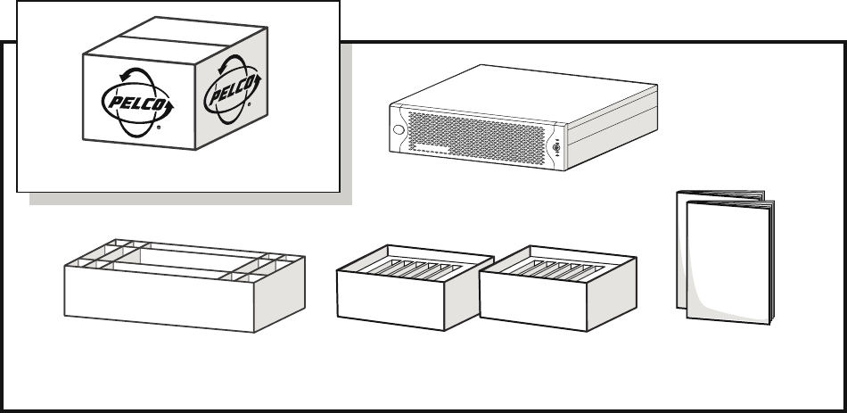
Figure 1. Major Package Components
PACKAGE CONTENTS
The following diagrams show the contents of the three boxes. When installing the NSM5200, refer to these diagrams.
ACCESSORY PACK HARD DRIVE PACK
(12 HARD DRIVES
IN CARRIERS)
NSM5200
SHIPPING BOX
SAFETY INSTRUCTIONS
INSTALLATION MANUAL
WEB CONFIGURATION MANUAL
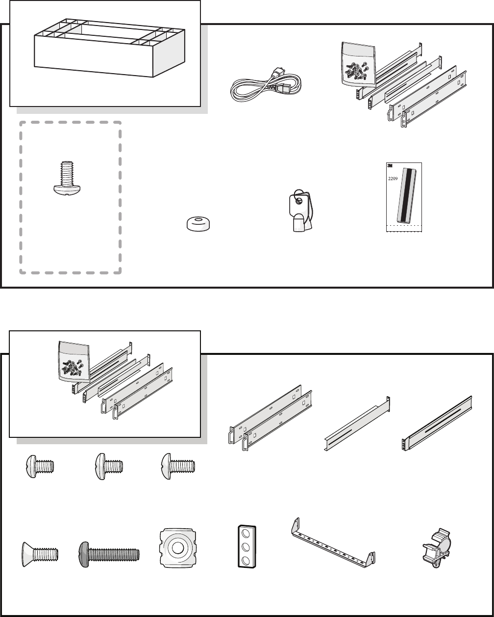
Figure 3. Rack Mount Kit
Figure 2. Accessory Pack
C3683M (3/09) 11
ACCESSORY PACK
PHILLIPS PAN
HEAD SCREW,
8-32 X 0. 375-INCH
5 EA.
(INSTALLED)
SHOWN ACTUAL SIZE
FRONT BEZEL KEY
2 EA.
RACK MOUNT KIT
ESD DISPOSABLE
WRIST STRAP
1 EA.
RUBBER FEET
5 EA.
(INSTALLED)
STANDARD
POWER CORD
2 EA.
RACK MOUNT KIT
CABLE MANAGEMENT
CLIP
3 EA.
CABLE MANAGEMENT
BRACKET
1 EA.
RACK RAIL
SPACER
2 EA.
CAGE NUT,
10-32
14 EA.
PHILLIPS PAN
HEAD SCREW,
10-32 X 0.75-INCH
4 EA.
PHILLIPS FLAT
HEAD SCREW,
10-32 X 0.5-INCH
8 EA.
FRONT MOUNT
RAIL
2 EA.
REAR MOUNT
RAIL
2 EA.
CHASSIS MOUNTING
BRACKETS
PHILLIPS TRUSS
HEAD SCREW,
8-32 X 0.375-INCH
8 EA.
PHILLIPS PAN
HEAD SCREW,
10-32 X 0.25- INCH
12 EA. (INSTALLED)
PHILLIPS PAN
HEAD SCREW,
6-32 X 0.25- INCH
2 EA.
12 C3683M (3/09)
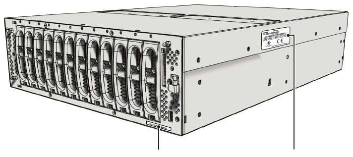
PRODUCT SERIAL NUMBER LABEL PLACEMENT
Product serial number labels help identify your system and its factory configuration in the event that your NSM5200 or its components require
service.
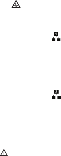
Three labels citing your product’s serial number are attached to the unit. One large label is attached to the right side panel of the unit. A smaller
label is attached to the unit’s front panel on the lower-left side, behind the front bezel.
Because rack mounting and other installation options may obscure the factory-applied labels, a third label is provided for you to attach to your
product documentation or other product location that will not be obscured by installation.
To use this label:
1. Locate the small label on the front bezel of your NSM5200, attached with a yellow sticker that reads, “Extra serial number labels: remove
prior to installation.”
2. Remove the yellow sticker.
Figure 4. Product Serial Number Labels
3. Peel away the backing of the small label and attach it to this installation manual, other product documentation, or an unobscured product
location.
03267-39-0020
SN
SERIAL NUMBER PRODUCT LABEL
C3683M (3/09) 13
Equipment Placement and Rack Mounting
The NSM5200 can be placed on a flat surface, such as a desktop, or mounted in an equipment rack.
DESKTOP INSTALLATION
To install the NSM5200 on a desktop:
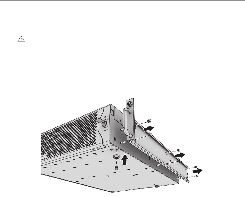
1. Make sure the rubber feet are installed to prevent surface damage. If not, secure each rubber foot to the bottom panel of the unit (refer to
Figure 5). Use the five 8-32 x 0.375-inch Phillips pan head screws (supplied).
2. Remove the two chassis brackets from the sides of the unit, if they are attached. Remove the 10-32 x 0.25-inch Phillips pan head screws
(six per bracket). Save the brackets and screws for possible future use.
Figure 5. Installing Rubber Feet and Removing Brackets
3. Position the unit to allow for cable and power cord clearance at the rear of the unit.
WARNING: Do not place the NSM5200 on its side; in this position, the unit is likely to fall over and may cause equipment damage or
personal injury.
M
5200
REMOVE BRACKETS
AND SCREWS

14 C3683M (3/09)
RACK MOUNTING
The NSM5200 mounts into an industry-standard 19-inch (48 cm) equipment rack. The NSM5200 occupies three rack units (5.25 in. or 13.3 cm) of
vertical rack space. The hardware necessary to mount the NSM5200 into a rack is supplied with the unit.
The rack must meet the following requirements:
• 19-inch (48 cm) EIA-310-D compliant (rear column required)
• Rack column depth: 24 to 30 inches (61 to 76 cm)
• Column mounting hole provisions: 10-32 UNF-2B threaded holes or square window holes on front and rear columns
• Door systems are acceptable. Front doors must have at least 2 inches (5.1 cm) between the NSM5200 front bezel and the inside of the door.
Rear doors may only be used on rack columns that are more than 26 inches (66 cm) deep.
To install the NSM5200 in a rack:
NOTE: Figure 3 on page 11 identifies each piece of hardware for this procedure.
Figure 6. Fastening Mounting Brackets to Chassis
1. If chassis mounting brackets are not attached: Attach one mounting bracket to each side of the NSM5200. Use six 10-32 x 0.25-inch Phillips
pan head screws for each bracket. Attach the brackets so that the tapered ends are positioned toward the rear of the unit.
2. Remove the rubber feet from the underside of the unit if they are attached.
WARNINGS:
• Secure the front and rear screws to the support rails.
• Make sure the NSM5200 is level.
• Slots and openings in the cabinet provide ventilation to prevent the unit from overheating. Do not block these openings. Never place
the unit near or over a radiator or heat register. When placing the unit in a rack, be sure to provide proper ventilation.
• Four of the six redundant fans are located in the upper-middle portion of the unit. If the unit must be pulled out to replace a fan, make
sure that all cables connected to the unit have sufficient length to avoid being disconnected.
M
5200
ATTACH BRACKETS
(6) SCREWS
10-32 X 0.25-INCH
PHILLIPS PAN HEAD
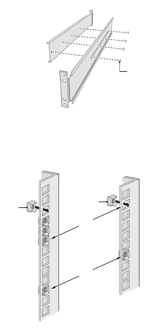
Figure 7. Assembling a Support Rail
C3683M (3/09) 15
3. Attach one front-mount rail to one rear-mount rail. Make sure the rails are mounted back to back, as shown in Figure 7. Depending on rack
depth, use either three or four 8-32 x 0.375-inch Phillips truss head screws for each rail set. Leave the screws loose until step 10.
4. Repeat step 3 for the other rail set.
Figure 8. Inserting Cage Nuts
5. If you are installing the unit into a square-hole rack: Insert 14 cage nuts into the square-hole rack as shown in Figure 8. Align the bottom
cage nuts on the front racks with the bottom cage nuts on the rear racks. Then align the top cage nuts with the front racks (refer to
Figure 8).
(4) SCREWS 8-32 X 0.375
PHILLIPS TRUSS HEAD
FRONT-MOUNT RACK REAR-MOUNT RACK
ALIGN
ALIGN
CAGE NUT
CAGE NUT
16 C3683M (3/09)
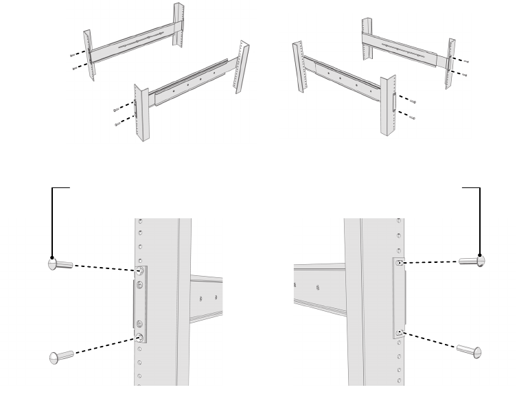
6. Attach one support rail assembly to the equipment rack in the desired location (refer to Figure 9):
NOTE: The support rail assemblies are identical and may be used on either the right or left side of the rack.
a. Position the ear of the front-mount rail against the front of the equipment rack. Align the top and bottom holes in the ear of the rail
with the threaded holes (or cage nuts) in the rack.
b. Using two 10-32 x 0.5-inch Phillips flat head screws, attach the ear of the rail to the front of the rack. Insert the screws from the
outside of the rack, pointing toward the back of the rack.
c. Adjust the rails to the correct depth of the equipment rack by sliding the rear-mount rail to the back of the equipment rack.
d. Position the ear of the rear-mount rail against the rear exterior of the equipment rack. Align the top and bottom holes in the ear of the
rail section with the threaded holes (or cage nuts) in the equipment rack.
e. Using two 10-32 x 0.75-inch Phillips pan head screws, attach the ear of the rail to the rear of the rack. Insert the screws from the
outside of the rack, pointing toward the front of the rack.
Figure 9. Attaching Support Rails
7. Repeat step 6 for the second support rail assembly (refer to Figure 9).
8. Attach one rack rail spacer to the front of the equipment rack (refer to Figure 10 on page 17):
a. Position the bottom hole of the spacer above the ear of the front-mount rail.
b. Insert two 10-32 x 0.5-inch Phillips flat head screws into the spacer, one in the top hole and one in the bottom hole. Leave the middle
hole empty; the top thumbscrew on the NSM5200 will use it.
(4) SCREWS
10-32 X 0.75-INCH
PHILLIPS PAN HEAD
(4) SCREWS
10-32 X 0.5-INCH
PHILLIPS FLAT HEAD
REAR-MOUNT RAILFRONT-MOUNT RAIL
RACK FRONT RACK REAR

Figure 10. Attaching Rack Rail Spacers
C3683M (3/09) 17
c. Tighten the two screws to secure the spacer to the rack.
9. Repeat step 8 for the second spacer.
10. Tighten the 8-32 x 0.375-inch Phillips truss head screws that were attached to the front- and rear-mount rails in steps 3 and 4.
Figure 11. Mounting the NSM5200 into the Rack
11. Place the unit onto the mount rails by sliding the chassis brackets onto the rails. This step may require two people to lift and slide the unit
into place. The unit should slide in and out of the rack easily.
NOTE: The NSM5200 stops mid-way in the rack to facilitate system fan replacement. To pull the NSM5200 completely out of the rack,
press the clips on either side of the rack to release the unit.
WARNING: When sliding out the NSM5200, be careful not to let the unit fall out of the rack or equipment damage or personal injury
could result.
10-32 X 0.5
PHILLIPS
FLATHEAD
SPACER
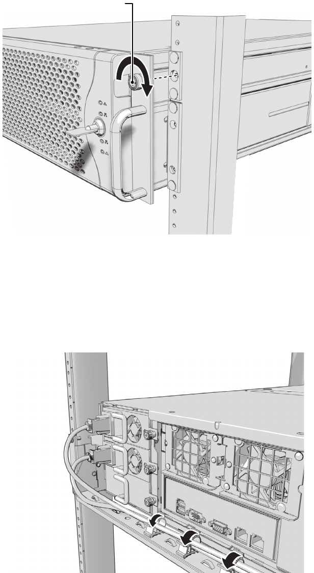
Figure 12. Tightening the Thumbscrews
Figure 13. Installing the Cable Management Bracket
18 C3683M (3/09)
12. After the unit is in place, tighten the two thumbscrews to secure the unit to the rack.
13. Install the cable management bracket on the rear panel as follows (refer to Figure 13):
a. Position the bracket so that the screw holes on the unit and bracket are aligned.
b. Insert two 6-32 x 0.25-inch Phillips pan head screws (supplied) into the screw holes located on each side of the unit.
c. Tighten the two screws.
d. Attach the three cable clips (supplied) to the cable management bracket.
14. Position the NSM5200 power supply cords along the cable management bracket, and then close the cable clips. You can also use cable ties
(not supplied) to bundle the power supply cords.
THUMBSCREW
C3683M (3/09) 19
Hard Drive Array Installation
The NSM5200 stores data using RAID (Redundant Array of Independent Disks) technology. All NSM5200 Series recorders operate in a RAID 6
configuration to maximize fault tolerance and enhance disk-access performance.
The NSM5200 has a single RAID controller that manages a single array of 12 drives. The RAID 6 configuration allows any 2 out of the 12 drives
to fail without any data loss. On any drive failure, the user is notified of the failure and the unit continues to operate.
INSTALLING HARD DRIVE CARRIERS
After you have securely mounted the NSM5200, install the 12 hard drives in the front of the chassis. Each hard drive is already mounted in its
own drive carrier so you can easily install and remove a hard drive, even while the unit is operating.
NOTE: You must install all 12 hard drive carriers before you apply power to the NSM5200. The hard drive bays are numbered 1 through 12
(starting from the left side). The hard drives are not preconfigured and can be placed in any empty hard drive bay.
To install the hard drive carriers:
1. Review all instructions in this section before proceeding.
2. Make sure you protect the unit and its components, which are susceptible to damage from improper handling and ESD. Refer to the Safe
Handling of Hard Drives document for more information.
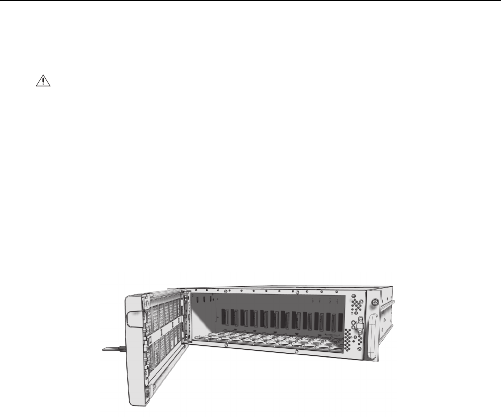
Figure 14. Opening the Front Bezel
3. Unlock and open the front bezel.
WARNING: If a third drive in the same array fails before either of the first two drives have been replaced, and have completed the rebuild
process, the array will go off line and data loss will occur.
123 4 5 6 7 8 910 11 12

Figure 15. Installing the Hard Drive Carrier
20 C3683M (3/09)
4. Install each hard drive carrier as follows:
a. Open the hard drive latch (press down and pull the spring latch).
b. With the hard drive latch open, slide the hard drive carrier gently into an open hard drive bay (refer to Figure 15).
c. Close the hard drive latch; make sure the hard drive carrier locks into place.
5. After all 12 hard drive carriers are inserted, close and lock the front bezel.
NOTE: During operation, monitor the unit status indicator lights to make sure that all drives are operating properly. If failure occurs, system
alarms and error messages will also display on Endura workstations and VCD5000 video console displays.
C3683M (3/09) 21
Connections
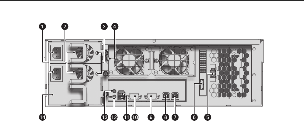
Figure 16. Rear Panel Layout
Familiarize yourself with the NSM5200 rear panel before connecting any equipment to the unit.
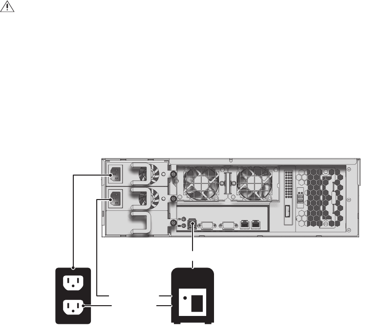
CONNECTING POWER
The NSM5200 is equipped with two hot-swappable power supplies. These autoranging power supplies adapt automatically to voltages from
100 to 240 VAC (50/60 Hz). You should also install an uninterruptible power supply (UPS), which is not supplied. UPS devices maintain a limited
amount of backup battery power if the main power fails. Refer to Appendix B: Installing an Uninterruptible Power Supply (UPS) on page 30 for
more information.
NOTE: Connect each power supply to a different branch circuit. This ensures optimal performance, reduces possible video loss, and reduces
power leakage to a safe level.
To connect the power supplies:
1. Connect each power cord to a power supply connector.
2. Connect the other end of each power cord to the appropriate power source.
When connected, the power supply status indicators glow solid red. As soon as the unit starts, the indicators glow solid green. During operation,
if either indicator is not lit or glows red, there is a problem with a power supply.
ì Power Supply Connectors (hot-swappable) t Ethernet Port 1
î Power Supplies (hot-swappable) u VGA Port
ï Power Supply LEDs (status) ~í Serial Port
ñ Mute button ~â USB 2.0 Ports (2)
ó Fibre Channel Connector ~ä Connector for Keyboard (purple)
r Mini-SAS Connector ~ã Connector for Mouse (green)
s Ethernet Port 2 (reserved for future use) ~å Power Supply (reserved for future use)
22 C3683M (3/09)
CONNECTING TO THE NETWORK
The NSM5200 supports remote administration from an Endura workstation. The NSM5200 is compatible with the entire family of Endura-ready
devices using TCP/IP and UPnP protocols. Consult your network administrator before installing the NSM5200 to avoid possible network conflicts.
Use the left Gigabit Ethernet adapter port to connect the NSM5200 to the Endura network. This is required for Endura operation.
NOTES: For best results, you should only implement an Endura system on a 1000Base-T network. Unless the Endura installation is very small
with a dedicated Endura network, a 100Base-T network will not support the necessary data throughput requirements.
To connect the NSM5200 to the Endura network using a switched Gigabit Ethernet network:
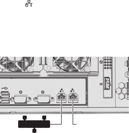
Figure 17. Network Cable Connection
1. Connect one end of the unshielded twisted pair (UTP) cable to the left network connector on the NSM5200 rear panel. Use standard Cat5e
or better UTP cable with RJ-45 connectors.
2. Connect the other end of the UTP cable to an available port on a Pelco-approved Gigabit Ethernet switch. Contact Pelco Product Support at
1-800-289-9100 (USA and Canada) or +1-559-292-1981 (international) for a list of approved Gigabit Ethernet switches.
There are two indicators on the network connector on the rear panel. The right indicator glows orange when there is a good connection
between the NSM5200 and a Gigabit Ethernet switch that is powered up. If the indicator does not glow, check the cable and the switch.
Disregard the left indicator, which shows network activity.
NSM5200
RESERVED
ENDURA NETWORK
ENDURA NETWORK
C3683M (3/09) 23
Operation
Refer to the Web Browser manual that was shipped with the unit for details on how to access and configure the NSM5200.
NOTE: To make sure that all diagnostic messages will appear to a system operator, leave at least one Endura workstation or VCD5000 running
at all times.
During operation, monitor the unit status and power supply indicator lights to make sure that all drives are operating properly. If failure occurs,
system alarms and error messages will also display on Endura workstations and VCD5000 video console displays.
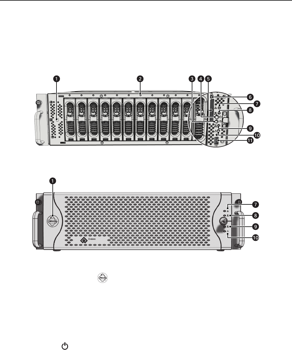
Figure 19. Front Bezel Indicators
Figure 18. Front Panel Layout
FRONT PANEL CONTROLS AND INDICATORS
ìPelco Badge (power indicator)
The Pelco badge glows blue when the unit has power. If the front bezel is open, this indicator glows white.
îDrive Status
The drive status indicator reports the operating status of each individual hard drive as follows:
•Solid Green: The read or write operation on a specific hard drive.
•Solid Red: A problem exists with the hard drive.
•Flashing Red: The unit is initializing the hard drive.
ïMute Button
Press the mute button to silence an alarm. The user must press the mute button for each alarm event.
ñPower Button
Use the power button to turn the unit on and off (refer to Unit Startup on page 25 and Unit Shutdown on page 25).
óCompact Flash Drive
Contains the Web configuration software
rCompact Flash Eject Button: Use this button to remove the CompactFlash drive.
1 2 3 4 5 6 7 8 9 10 11 12
NSM5200
24 C3683M (3/09)
sSoftware Status
•Green: The software is operating normally.
•Amber: A minor software malfunction is detected (for example, an excessive network packet loss).
•Red: A fatal software error has occurred: for example, ceasing to record.
tNetwork Port 1 Speed and Activity
Network status (connection and speed) is indicated by one of the following conditions:
•Off: The unit is not connected to the network.
•Solid Green: The unit is connected to the network using the 1000Base-T standard.
•Solid Amber: The unit is connected to the network using the 100Base-T standard.
•Solid Red: The unit is connected to the network using the 10Base-T standard.
NOTE: For proper operation, you must use the 1000Base-T standard.
uNetwork Port 2 Speed and Activity
Network status (connection and speed) is indicated by one of the following conditions:
•Off: The unit is not connected to the network.
•Solid Green: The unit is connected to the network using the 1000Base-T standard.
•Solid Amber: The unit is connected to the network using the 100Base-T standard.
•Solid Red: The unit is connected to the network using the 10Base-T standard.
NOTE: For proper operation, you must use the 1000Base-T standard.
~í Unit Status
Unit status is indicated by one of the following three colors:
•Green: The unit is functioning normally.
•Amber: The unit is in configuration mode.
•Red: The unit is in an error condition (refer to Troubleshooting on page 26).
~â USB 2.0 Port: One USB 2.0 port on the front panel.
C3683M (3/09) 25
UNIT STARTUP
To start the unit:
1. Unlock and open the front bezel.
2. Press the power button. The power indicator glows white.
Figure 20. Opening the Front Bezel
3. Close and lock the front bezel. The Pelco badge now glows blue.
UNIT SHUTDOWN
You can shut down the NSM5200 by performing one of the following options:
• An orderly shutdown lets the unit close its files and shut down without affecting the data files. Use the orderly shutdown in most cases.
• An immediate shutdown is the same as disconnecting power and can result in corrupted data files. Only use the immediate shutdown in an
emergency or when there is not enough time for an orderly shutdown.
To shut down the unit:
1. Unlock and open the front bezel.
2. Select one of the following options:
• For an orderly shutdown, press and release the power button quickly.
• For an immediate shutdown, press and hold the power button until the unit shuts down.
3. Close and lock the front bezel.
123 4 5 6 7 8 910 11 12
POWER BUTTON

26 C3683M (3/09)
Troubleshooting
If the following instructions fail to solve your problem, contact Pelco’s Product Support at 1-800-289-9100 (USA and Canada) or +1-559-292-1981
(international) for assistance.
Access the properties dialog boxes for the NSM5200 on the Endura workstation. Refer to the Endura WS5000 Software Operation manual, and
then note the following items before contacting Pelco:
•Unit serial number: Located in the Properties window and on the product label
•Software version: Located in the Advanced Properties dialog box
NOTE: Do not try to repair the unit yourself. Opening it immediately voids any warranty. Leave maintenance and repairs to qualified technical
personnel. Exchange the defective unit and return it for repair.
NSM5200
POWER SUPPLIES
The two power supplies are equipped with status indicators. Replace the appropriate power supply if a failure should occur. Table C describes
the status by color and indicator.
Table B. Troubleshooting
Problem Possible Causes Suggested Remedy
Unit not ready. Power turned off. Check that the power indicator is lit.
Faulty cable connections. Check all leads, plugs, contacts, and connections.
Defective encoder. Check the camera on a different encoder.
Network connectivity issues. Contact your network administrator.
The unit is not ready for operation
after firmware upload.
Voltage failure during programming
of update file.
Replace the NSM5200 and have it checked by Pelco.
Unit status indicator is red. Unit fan failure. Replace the failed fan.
Power supply failure.
Temperature exceeds specifications
(internal or external).
Check power supplies.
Check all fans; check the external temperature.
Unit status indicator is red and
the power supply alarm sounds.
Power loss to either power supply. Check each power supply, line voltage, and the UPS.
Power supply module failure. Replace the failed power supply.
Unit status and hard drive
indicators are red and the unit
alarm sounds.
Hard drive failure. Replace the failed hard drive.
Table C. Status Indicators
Power Supply Status Power Supply Indicator Front Panel Status Indicator Power Supply Audible Alarm
Normal Solid green Solid green Silent
Power problem Solid red Solid red Alarm sounds
Power supply failure Not lit or solid red Solid red Alarm sounds

C3683M (3/09) 27
Specifications
SYSTEM
Operating System Linux
RAID Level CompactFlash system drive, RAID 6 for storage drives
Effective Capacity Up to 9.082 TB, expandable with DAS5200s
Drive Interface SAS/SATA II
User Interface Remote operation from Endura workstation or VCD5000
Minimum Requirements Microsoft® Internet Explorer® 6.x or higher with Adobe® Flash® Player 10 or later
NETWORK
Interface 2, 1 Gbps Ethernet RJ-45 ports (1000Base-T)
Auxiliary Interfaces
USB 2.0 3 ports: 2 ports on rear panel, 1 port on front panel
FRONT PANEL INDICATORS
Power Blue Pelco badge
Software Status Green, Amber, Red (based on diagnostics)
Ethernet Port 1 Green, Amber, Red
Ethernet Port 2 Reserved
Hardware Status Green, Amber, Red
Hard Drive Status Green, Red
POWER
Power Input 100 to 240 VAC, 50/60 Hz, autoranging
Power Supply Internal, dual-redundant, hot-swappable
Power Consumption Operating Average
262 W, 2.65 A, 895 BTU/H
263 W, 2.31 A, 895 BTU/H
254 W, 1.25 A, 868 BTU/H
Power Cord 1, USA standard (117 VAC, 3 prongs, molded connector, 6 ft or 1.8 m) or
1, European standard (220 VAC, 3 prongs, molded connector, 6 ft or 1.8 m) or
1, UK standard (250 VAC, 3 prongs, molded connector, 6 ft or 1.8 m) or
2, Australian (250 VAC, 3 prongs, molded connector, 6 ft or 1.8 m) or
2, Argentinian (250 VAC, 3 prongs, molded connector, 8 ft or 2.4 m)
NOTE: Units shipped to China do not include power cords.
ENVIRONMENTAL
Operating Temperature 50° to 95°F (10° to 35°C) at unit air intake
Storage Temperature -40° to 149°F (-40° to 65°C)
Operating Humidity 20% to 80%, noncondensing
Maximum Humidity Gradient 10% per hour
Operating Altitude -50 to 10,000 ft (-16 to 3,048 m)
Operating Vibration 0.25 G at 3 Hz to 200 Hz at a sweep rate of 0.5 octave/minute
NOTE: The temperature at the unit air intake can be significantly higher than room temperature. Temperature is affected by rack configuration,
floor layout, air conditioning strategy, and other issues. To prevent performance failure and unit damage, make sure the temperature at the unit is
continuously within the operating temperature range.
28 C3683M (3/09)
PHYSICAL
Construction Steel cabinet
Finish
Front bezel Gray metallic with black end caps
Chassis Black matte finish
Dimensions 24.3" D x 17.0" W x 5.2" H
(61.8 x 43.2 x 13.2 cm)
Mounting Desktop (feet)
Rack, 3 RU per unit
(Rack rails and hardware provided)
STANDARDS/ORGANIZATIONS
• Pelco is a member of the MPEG-4 Industry Forum
• Pelco is a member of the Universal Plug and Play (UPnP) Forum
• Pelco is a member of the Universal Serial Bus (USB) Implementers Forum
• Pelco is a contributor to the International Standards for Organization/Electrotechnical Commission (ISO/IEC) Joint Technical Committee
1 (JTC1), “Information Technology,” Subcommittee 29, Working Group 11
• Compliance, ISO/IEC 14496 standard (also known as MPEG-4)
• Compliant with International Telecommunication Union (ITU) Recommendation G.711, “Pulse Code Modulation (PCM) of Voice Frequencies”
(Design and product specifications subject to change without notice.)
C3683M (3/09) 29
Appendices
APPENDIX A: EXPANDING VIDEO STORAGE
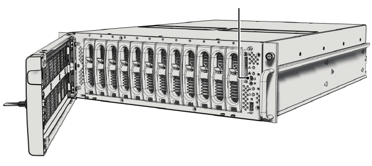
You can increase the video storage capacity of the NSM5200 by adding one or more DAS5200 direct attached storage (DAS). Each DAS5200 adds
up to 12.0 TB of total capacity (up to 9.08 TB of video storage). You can add up to seven DAS5200 units to expand the total capacity for each
NSM5200 up to 81 TB of total capacity (up to 72.6 TB of video storage).
NOTES:
• You do not have to shut down the NSM5200 to add a DAS5200.
• The NSM5200 has one mini-SAS connector on the rear panel; the DAS5200 has two mini-SAS connectors on the rear panel.
• A maximum of seven DAS5200s can be connected (daisy-chained) to a single NSM5200.
To connect one or more DAS5200s to an NSM5200:
NOTE: A rack setup is used in the following configuration.
1. Install the NSM5200 and the DAS5200 (one or more) into a rack system.
2. Connect a mini-SAS cable to the SAS connector on the rear panel of the NSM5200.
3. Connect the other end of the mini-SAS cable to the top SAS connector (IN) on the rear panel of the DAS5200.
4. For each additional DAS5200:
a. Connect the mini-SAS cable to the bottom SAS connector (OUT) on the rear panel of the DAS5200.
b. Connect the other end of the mini-SAS cable to the top SAS connector (IN) on the rear panel of the next DAS5200.
Figure 21. DAS5200s Connected to an NSM5200
Figure 21 displays an NSM5200 with three DAS5200s connected. The configuration is a daisy-chain setup.
5. Power up the DAS5200, if necessary. Refer to the DAS5200 Series Installation manual for more information.
6. Power up the NSM5200, if necessary (refer to Unit Startup on page 25).
The NSM5200 automatically recognizes the new DAS5200 unit within five minutes, and then puts it into service.
MINI-SAS CABLE
MINI-SAS CABLE
MINI-SAS CABLE
DAS5200
DAS5200
DAS5200
NSM5200
ENDURA NETWORK
ENDURA NETWORK
30 C3683M (3/09)
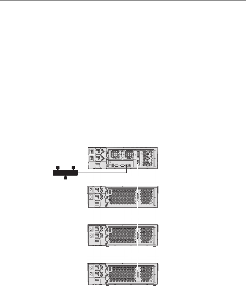
APPENDIX B: INSTALLING AN UNINTERRUPTIBLE POWER SUPPLY (UPS)
You should connect each NSM5200 to a UPS (not supplied). UPS devices maintain a limited amount of backup battery power if the main power fails.
To connect communication and power from the UPS to the NSM5200 (refer to Figure 22):
1. Connect a power cord from one of the NSM5200 power supplies to a standard wall socket.
2. Connect a power cord from the UPS to a standard wall socket or other power source.
3. Connect a power cord from the UPS to the other NSM5200 power supply. In this configuration, the unit will not lose power if either the
power source or the UPS fails.
4. Power up the UPS device.
Figure 22. Connecting a UPS to an NSM5200
5. Power up the NSM5200, if necessary (refer to Unit Startup on page 25).
WARNING: Most UPS devices can be used to supply backup battery power. However, the NSM5200 does not support intelligent UPS
devices since they usually include power management software. If you install an intelligent UPS device, do not install the power
management software on the NSM5200.
UPS
POWER SOURCE
INPUT POWER
USB
OUTPUT POWER

PRODUCT WARRANTY AND RETURN INFORMATION
WARRANTY
Pelco will repair or replace, without charge, any merchandise proved defective in
material or workmanship for a period of one year after the date of shipment.
Exceptions to this warranty are as noted below:
• Five years:
– Fiber optic products
– TW3000 Series unshielded twisted pair (UTP) transmission products
– CC3701H-2, CC3701H-2X, CC3751H-2, CC3651H-2X, MC3651H-2, and
MC3651H-2X camera models
• Three years:
– Pelco-branded fixed camera models (CCC1390H Series, C10DN Series,
C10CH Series, IP3701H Series, and IX Series)
– EH1500 Series enclosures
– Spectra® IV products (including Spectra IV IP)
– Camclosure® Series (IS, ICS, IP) integrated camera systems
– DX Series digital video recorders, DVR5100 Series digital video recorders,
Digital Sentry® Series hardware products, DVX Series digital video
recorders, and NVR300 Series network video recorders
– Endura® Series distributed network-based video products
– Genex® Series products (multiplexers, server, and keyboard)
– PMCL200/300/400 Series LCD monitors
• Two years:
– Standard varifocal, fixed focal, and motorized zoom lenses
– DF5/DF8 Series fixed dome products
– Legacy® Series integrated positioning systems
– Spectra III™, Spectra Mini, Spectra Mini IP, Esprit®, ExSite®, and PS20
scanners, including when used in continuous motion applications.
– Esprit Ti and TI2500 Series thermal imaging products
– Esprit and WW5700 Series window wiper (excluding wiper blades).
– CM6700/CM6800/CM9700 Series matrix
– Digital Light Processing (DLP®) displays (except lamp and color wheel). The
lamp and color wheel will be covered for a period of 90 days. The air filter is
not covered under warranty.
– Intelli-M® eIDC controllers
• One year:
– Video cassette recorders (VCRs), except video heads. Video heads will be
covered for a period of six months.
•Six months:
– All pan and tilts, scanners, or preset lenses used in continuous motion
applications (preset scan, tour, and auto scan modes).
Pelco will warrant all replacement parts and repairs for 90 days from the date of
Pelco shipment. All goods requiring warranty repair shall be sent freight prepaid
to a Pelco designated location. Repairs made necessary by reason of misuse,
alteration, normal wear, or accident are not covered under this warranty.
Pelco assumes no risk and shall be subject to no liability for damages or loss
resulting from the specific use or application made of the Products. Pelco’s liability
for any claim, whether based on breach of contract, negligence, infringement of
any rights of any party or product liability, relating to the Products shall not exceed
the price paid by the Dealer to Pelco for such Products. In no event will Pelco be
liable for any special, incidental, or consequential damages (including loss of use,
loss of profit, and claims of third parties) however caused, whether by the
negligence of Pelco or otherwise.
The above warranty provides the Dealer with specific legal rights. The Dealer may
also have additional rights, which are subject to variation from state to state.
If a warranty repair is required, the Dealer must contact Pelco at (800) 289-9100 or
(559) 292-1981 to obtain a Repair Authorization number (RA), and provide the
following information:
1. Model and serial number
2. Date of shipment, P.O. number, sales order number, or Pelco invoice number
3. Details of the defect or problem
If there is a dispute regarding the warranty of a product that does not fall under
the warranty conditions stated above, please include a written explanation with
the product when returned.
Method of return shipment shall be the same or equal to the method by which the
item was received by Pelco.
RETURNS
To expedite parts returned for repair or credit, please call Pelco at (800) 289-9100
or (559) 292-1981 to obtain an authorization number (CA number if returned for
credit, and RA number if returned for repair) and designated return location.
All merchandise returned for credit may be subject to a 20 percent restocking and
refurbishing charge.
Goods returned for repair or credit should be clearly identified with the assigned
CA or RA number and freight should be prepaid.
The materials used in the manufacture of this document and its components are compliant to the requirements of Directive 2002/95/EC.
This equipment contains electrical or electronic components that must be recycled properly to comply with Directive 2002/96/EC of the European Union
regarding the disposal of waste electrical and electronic equipment (WEEE). Contact your local dealer for procedures for recycling this equipment.
12-23-08
REVISION HISTORY
Manual # Date Comments
C3683M 3/09 Original version.
Pelco, the Pelco logo, Camclosure, Digital Sentry, Endura, Esprit, ExSite, Genex, Intelli-M, Legacy, and Spectra are registered trademarks of Pelco, Inc. © Copyright 2009, Pelco, Inc. All rights reserved.
Spectra III is a trademark of Pelco, Inc.
All product names and services identified throughout this document are trademarks or registered trademarks of their respective companies.
The absence of a trademark or registered trademark from this document does not constitute a waiver of intellectual property rights.