Pelco Kbd300V Users Manual C526M D
kbd300v 46de1727-016d-410c-8c8d-29510c103b71 Pelco Video Game Keyboard KBD300V User Guide |
2015-02-02
: Pelco Pelco-Kbd300V-Users-Manual-441693 pelco-kbd300v-users-manual-441693 pelco pdf
Open the PDF directly: View PDF ![]() .
.
Page Count: 16
- CONTENTS
- IMPORTANT SAFEGUARDS AND WARNINGS
- Regulatory Notices
- DESCRIPTION
- Models
- INSTALLATION - CM6700 MODE
- INSTALLATION - DIRECT MODE
- SWITCH SETTINGS
- PROGRAMMING AND OPERATION
- Scanning Functions
- Programming Limit Stops
- Zones
- SPECIFICATIONS
- INDEX
- Acknowledge
- Auxiliaries
- Clear
- DIP switch
- Firmware version
- Genex multiplexer
- Installation
- CM6700 Mode
- Direct Mode
- Keyboard addresses
- LED
- Lens Control
- Limit stops
- Macro sequence
- Multiplexer displays
- Operation
- Operational features
- Pan/Tilt
- Patterns
- Presets
- Program
- Programming
- Regulatory notices
- Relays
- Returns
- Safeguards
- Scanning
- Select camera
- Select monitor
- Sequence
- Specifications
- Switch settings
- Warranty
- Zoom
- WARRANTY AND RETURN INFORMATION
- List of Illustrations
- List of Tables
Pelco • 3500 Pelco Way • Clovis, CA 93612-5699 USA • Pelco Online @ http://www.pelco.com
In North America and Canada: Tel (800) 289-9100 or FAX (800) 289-9150 • DataFAX (800) 289-9108
International Customers: Tel +1 (559) 292-1981 or FAX +1 (559) 348-1120 • DataFAX +1 (559) 292-0435
PelcoEurope BV • Dillenburg Center, Dillenburgstraat 5F • 5652 AM Eindhoven • The Netherlands
Tel +31(40) 251-9870 • FAX +31(40) 251-9835
®
Installation/Operation
KBD300V
Universal Keyboard
C519M-D (7/00)
SHIFT
SEQUENCE
F1F2F3F4F5
MONACK PREVNEXTHOLDPATTE RN PRESETMACROPGM
123
456
789
0CLEAR
CAM
KBD300
MADE IN USA.

[ 2 ] Pelco Manual C519M-D (7/00)
IMPORTANT SAFEGUARDS AND WARNINGS
Prior to installation and use of this product, the following WARNINGS should be observed.
1. Installation and servicing should only be done by qualified service personnel and conform to all local
codes.
2. This unit is designed for indoor use only, and it must not be installed where exposed to rain and
moisture.
3. Only use replacement parts recommended by Pelco.
4. After replacement/repair of this unit’s electrical components, conduct a resistance measurement be-
tween line and exposed parts to verify the exposed parts have not been connected to line circuitry.
Please thoroughly familiarize yourself with the information in this manual prior to installation and operation.
Regulatory Notices
NOTE: This equipment has been tested and found to comply with the limits of a Class A digital device,
pursuant to part 15 of the FCC rules. These limits are designed to provide reasonable protection against
harmful interference when the equipment is operated in a commercial environment. This equipment gen-
erates, uses, and can radiate radio frequency energy and, if not installed and used in accordance with the
instruction manual, may cause harmful interference to radio communications. Operation of this equipment
in a residential area is likely to cause harmful interference in which case the user will be required to cor-
rect the interference at his own expense.
CONTENTS
Section Page
IMPORTANT SAFEGUARDS AND WARNINGS ........................................................................................2
Regulatory Notices ............................................................................................................................2
DESCRIPTION ...........................................................................................................................................3
Models ..............................................................................................................................................3
INSTALLATION - CM6700 MODE ..............................................................................................................4
INSTALLATION - DIRECT MODE...............................................................................................................6
SWITCH SETTINGS ...................................................................................................................................8
PROGRAMMING AND OPERATION ..........................................................................................................9
Scanning Functions.........................................................................................................................12
Programming Limit Stops................................................................................................................12
Zones ..............................................................................................................................................13
SPECIFICATIONS ....................................................................................................................................14
INDEX .......................................................................................................................................................15
WARRANTY AND RETURN INFORMATION ...........................................................................................16
Pelco Manual C519M-D (7/00) [ 3 ]
DESCRIPTION
The KBD300V Universal Keyboard can be used in two operational modes. The KBD300V includes a
5-inch (12.7 cm) diagonal color monitor to make a complete, stand-alone viewing and control package.
CM6700 Mode: Program and operate the CM6700 Matrix Switcher/Controller Unit (SCU). Also control a
Genex® multiplexer from a CM6700 SCU. Multiple keyboards can be used in this mode. (The KBD300V
cannot be connected to the local keyboard port.)
Direct Mode: Control up to 16 receivers connected directly to the keyboard. Only one keyboard can be
used in this mode. A separate system, such as an MS500 or VA6100 Switcher, is needed to route video
to the monitor.
Models
KBD300V Keyboard with monitor, 120 VAC, 60 Hz, NTSC (CE, FCC)
KBD300V-X Keyboard with monitor, 230 VAC, 50 Hz, PAL (CE)
Figure 1. KBD300V Applications
Table A. KBD300V Operational Features
Function CM6700 Mode Direct Mode
Select cameras Yes Yes
Select monitors Yes No
Control lenses Yes Yes
Set and call presets/patterns Yes Yes
Control latching receiver auxiliaries Yes Yes
Control momentary receiver auxiliaries Yes Yes
Control multiplexer Yes No
Control CM6700 Matrix Switcher Yes No
Program CM6700 Matrix Switcher Yes No
Sequencing Yes No
Operate frame, auto, and random scans Yes Yes
Program and operate patterns* Yes Yes
* Firmware version 4.0 and higher
MULTIPLEXER
(OPTIONAL)
CM6700
CAMERA CONTROL
FROM CAMERAS
TO
MONITORS
REMOTE
KEYBOARDS
REMOTE
PORT
LOCAL
PORT
CM6700 MODE DIRECT MODE
SWITCH
RECEIVER
CAMERA
RECEIVER RECEIVERRECEIVER
CAMERA CAMERA CAMERA
1 TO 16
TO MONITORS
FROM
CAMERAS
CONTROL DATA
VIDEO
KBD200
KBD300V
KBD300V
KBD300V
LOOPED
CAMERA
INPUT
KBD300VMONITOR

[ 4 ] Pelco Manual C519M-D (7/00)
INSTALLATION - CM6700 MODE
NOTE:
There are two keyboard ports on the CM6700 SCU. The LOCAL KEYBOARD port cannot be
used for the KBD300V.
To install KBD300V keyboards at the REMOTE KEYBOARD(S) port:
Refer to Figure 2. A KBD300V Interface is used to connect the KBD300V keyboard to the Remote
Keyboard port on the back of the SCU or to another KBD300V Interface in a daisy-chain hookup. It can
also connect to a wall block on either its input side or on its output side. You can have as many KBD300V
keyboards as you have monitor outputs on your SCU.
1Select a suitable location for the keyboard and interface. The interface must be within 6 feet (1.8 m)
of a suitable electrical outlet and within 6 feet (1.8 m) of the keyboard. Attach the interface to the wall
or other surface with the screws that are provided. Remove the cover if necessary, and replace when
finished.
2Connect a five-conductor (or larger) cable (user-supplied) from the SCU (or from a wall block or an-
other interface) to the interface. Connect wires at the COM IN terminals. If additional keyboards follow
the KBD300V, connect a cable from the interface output terminals to the next wall block or interface.
3Connect a video cable from a monitor output on the SCU to the VIDEO IN jack on the interface.
4Set the keyboard address switches for each keyboard according to the instructions on page 8.
5Connect the keyboard data cable between the interface and the keyboard.
6Connect the power supply to the interface and plug the transformer end into a suitable outlet.
7Turn on the power switch on the back of the keyboard and apply power to the SCU (if not already
powered.
8To initialize the keyboard, wait five seconds after power up, enter the number for the monitor you are
viewing (1-4), and press MON. The LED display shows the number entered.
NOTE:
You must re-initialize whenever power is cycled.
9Go to the
Programming and Operation
section and program and test for proper operation.
Pelco Manual C519M-D (7/00) [ 5 ]
Figure 2. Wiring Diagram for Remote Keyboards
LOCAL
KBD300V
INTERFACE
SCU
R+
R-
T-
T+
R+
R-
T-
T+
VIDEO
OUTPUTS
1
47
5
6
3
2
POWER SUPPLY
RX+
RX-
GND
TX-
TX+
TO ADDITIONAL KBD300V
INTERFACES OR TO WALL
BLOCKS (NON-KBD300V
KEYBOARDS)
RX+
RX-
GND
TX-
TX+
TO SCU OR PREVIOUS
KBD300V INTERFACE
OR TO WALL BLOCKS
(NON-KBD300V
KEYBOARDS)
R+R-T-T+
EACH KBD300V
REQUIRES A VIDEO
CONNECTION TO A
MONITOR OUTPUT
ON THE SCU.
INTERFACE CABLE (CARRIES CONTROL SIGNALS AND VIDEO)

[ 6 ] Pelco Manual C519M-D (7/00)
10 Turn on the power switch on the back of the keyboard. The monitor comes on.
11 Go to the
Programming and Operation
section and program and test for proper operation.
INSTALLATION - DIRECT MODE
Direct Mode is for a single-keyboard installation only. The keyboard is wired directly to a maximum of 16
receivers. Direct Mode installation/operation is not the same as CM6700 Mode installation/operation. A
separate system, such as an MS500 or VA6100 switcher, is required for routing video to the monitor(s).
To connect the keyboard (refer to Figure 3).
1Make sure all receivers are configured to communicate using Pelco P protocol at 4800 baud and that
each receiver has a unique address. Refer to your receiver manual for switch settings.
2Decide on a suitable location for the keyboard and interface module. The interface module must be
within 6 feet (1.8 m) of the keyboard and of the nearest suitable electrical outlet.
3Attach the KBD300V Interface module to the wall with the provided screws. Remove the cover, if nec-
essary, and replace when finished.
4Receiver wiring should be in place before installing the keyboard. You can control up to 16 receivers
from the keyboard.
Communication to the keyboards is RS-485. Maximum cable distance for RS-485 communication
over 24-gauge wire is 4,000 feet (1,219 m). Pelco recommends using shielded twisted pairs cable
that meets or exceeds the basic requirements for EIA RS-485 applications.
5Refer to Figure 3. Make receiver cable connections to the COM OUT terminals on the interface module.
• Connect the TX+ terminal from COM OUT on the interface module to RX+ on the receiver.
• Connect the TX- terminal from COM OUT on the interface module to RX- on the receiver.
• Connect the ground terminal to the ground terminal on the receiver. (A ground connection
may not be necessary if another ground path already exists).
6Connect a video coaxial cable from the video out jack on a video switcher to the VIDEO IN jack on
the interface module.
7Set the keyboard DIP switches for Direct Mode according to the instructions on page 8.
8Connect the keyboard data cable between the interface and the keyboard.
9Connect the power supply to the interface and plug the transformer end into a suitable outlet. The
LED display shows number 1, which is the default camera number.
Pelco Manual C519M-D (7/00) [ 7 ]
Figure 3. Keyboard Cabling Diagram
VIDEO POWER
ON
OFF
INTERFACE
CABLE
POWER SUPPLY
KBD300V
VIDEO COAX
CABLE INPUT
COMMUNICATION
CABLE
TO RECEIVER
C
O
M
I
N
C
O
M
O
U
T
R+
R–
T–
T+
R+
R–
T–
T+
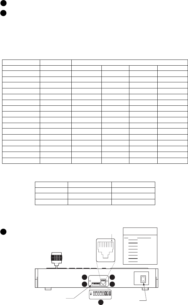
[ 8 ] Pelco Manual C519M-D (7/00)
Figure 4. Keyboard Rear Panel
SWITCH SETTINGS
To set the switches on the keyboard (refer to Figure 4):
1 Remove the two screws and the DIP switch cover plate from the rear of the keyboard.
2 Set the switches:
• Address (Switches 1-4)
Position the switches according to Table B. Each keyboard in the system must have a
different address, including the local keyboard. To make programming easier, address
keyboards in ascending order.
NOTE:
CM6700 accepts only eight addresses.
Table B. Keyboard Addresses
Keyboard Address Switch Settings
1234
1 0 OFF OFF OFF OFF
2 1 ON OFF OFF OFF
3 2 OFF ON OFF OFF
4 3 ON ON OFF OFF
5 4 OFF OFF ON OFF
6 5 ON OFF ON OFF
7 6 OFF ON ON OFF
8 7 ON ON ON OFF
9 8 OFF OFF OFF ON
10 9 ON OFF OFF ON
11 10 OFF ON OFF ON
12 11 ON ON OFF ON
13 12 OFF OFF ON ON
14 13 ON OFF ON ON
15 14 OFF ON ON ON
16 15 ON ON ON ON
• Mode (Switches 5, 6, 8)
Table C. Keyboard Modes
CM6700 Direct
Switch 5 OFF ON
Switch 6* ON or OFF* ON or OFF*
Switch 8 OFF OFF
* Switch 6 enables/disables turbo pan. (Can be switched while keyboard is on.)
• Not Used (Switch 7)
3Replace the cover plate.
RJ-45 JACK
PIN FUNCTIONS TABLE
PIN FUNCTION
1 Tx+
2 Tx-
3 +12 VDC
4 DC COMMON
5 GROUND
6 COMP. VIDEO
7 Rx-
8 Rx+
PIN 1
VIDEO POWER
ON
OFF
ON
1 2 3 4 5 6 7 8
ON
1 2 3 4 5 6 7 8
MONITOR ON/OFF
SWITCH
KEYBOARD
DIP SWITCH
(BENEATH COVER)
3
1
3
1
2
Pelco Manual C519M-D (7/00) [ 9 ]
PROGRAMMING AND OPERATION
Table D. Keyboard Functions
Circled numbers refer to Figure 5.
Function Procedure
Select Monitor* LED display 1 shows monitor number in run mode.
Enter monitor number (1-4) 15 and press MON 17 to select.
NOTE: To view and control cameras on a monitor other than the one on the
keyboard, enter the number of that monitor.
Select Camera Enter camera number (1-16) 15 and press CAM 14 to select.
NOTE: The CM6700 can be programmed to restrict some monitors from view-
ing certain cameras. To display a camera’s view on your monitor, be sure that
your keyboard shows the number of the monitor you are viewing and be sure
that the CM6700 has not been programmed to restrict viewing of that camera.
Pan/Tilt/Zoom Move the joystick 12 until the camera reaches the desired position. To in-
crease the speed of movement, move the joystick further from center. Twist
the joystick clockwise to zoom in, counterclockwise to zoom out.
Lens Control Focus, iris - Press and hold the appropriate lens control key 11 until the de-
sired effect is seen.
Presets Enter preset number (1-66) 15 and press PRESET 9 to put camera in
preset position.
To program, position camera, enter desired preset number (1-66) 15 , and
hold down PRESET 9 for two seconds.
In CM6700 mode, a label appears on the monitor. Use F1 and F2 5 to edit
the label, then select SET and press ACK 16 .
Patterns Programming and operation varies with the receiver type.
Spectra® domes (before version 3.0) can use one long (1 minute) or two
short (0.5 minute) patterns. Spectra domes (version 3.0), Spectra II™
domes and Esprit™ Integrated Positioning Systems can use one long
(1.5, 3 or 6 minutes) or two short (0.75, 1.5 or 3 minutes) patterns. (Select
pattern lengths at the positioning system’s menu.)
To program Spectra and Esprit, select a camera (1-16) 15 , select a long
pattern by holding down PATTERN 10 for two seconds, or select short pat-
tern 1 or 2 by entering 1 or 2 15 and holding down PATTERN 10 for two
seconds. The monitor will indicate the programming function is active. Move
the camera position 12 as desired for the pattern and press ACK 16 to
close the programming function.
To run a long pattern, press PATTERN 10 . To run a short pattern, enter 1 or
2 15 and press PATTERN 10 . Move the joystick 12 or call a preset 9
to stop.
Direct Mode is the same as above, except:
Do not program a pattern with turbo pan on (switch 6).
*This function is not used in Direct Mode.
Continued on next page
[ 10 ] Pelco Manual C519M-D (7/00)
Table D. Keyboard Functions (continued)
Function Procedure
Sequence* Sequence steps through all 16 cameras. Camera number, camera title,
sequence status, and time/date are shown on the monitor.
Press PREV 4A to step back one camera. Hold for two seconds for a back-
ward sequence. Monitor shows B. Press during sequence to speed up. Press
during a forward sequence to reverse.
Press NEXT 4B to step forward one camera. Hold for two seconds for a for-
ward sequence. Monitor shows F. Press during sequence to speed up. Press
during a backward sequence to go forward.
Press HOLD 4C to hold a sequence. Monitor shows H. Press PREV or
NEXT to resume.
Manually select a camera or press CAM 14 to turn off a sequence. Monitor
shows O.
Macro Sequence* Enter 1 or 2 15 and press MACRO 8 to start a group camera sequence. Moni-
tor shows M. Refer to the CM6700 manual for macro/sequence programming.
Multiplexer Press SHIFT 2 . Shift key LED 3 lights. The function keys F1 through F5
Displays* can now be used to display the images from multiple cameras on the monitor.
F1: Zoom
F2: PIP display
F3: Quad display
F4: 9-screen display
F5: 16-screen display
Auxiliaries/ F1 – F3 5 control only the auxiliaries built into the CM6700 SCU.
Relays These outputs can be programmed for momentary, keyed, latched, or alarm
operation. Refer to the CM6700 manual for programming instructions.
F1: Activate/deactivate auxiliary 1 relay.*
F2: Activate/deactivate switcher auxiliary 2 TTL output.*
F3: Activate/deactivate switcher auxiliary 3 TTL output.*
F4 and F5 control the auxiliaries in receivers.
Enter the auxiliary number and press F4 to turn on. Hold, then release for
momentary functions.
Enter the auxiliary number and press F5 to turn off.
In Direct Mode, F1- F3 5 have no function. LED 1 shows auxiliary num-
ber for two seconds after F4 or F5 5 is pressed.
Acknowledge Press ACK 16 to acknowledge an alarm. Refer to the CM6700 manual for
Alarm* further information on alarms.
Program To program the CM6700 switcher, press PGM 7 .
(CM6700) Follow the programming procedure in the CM6700 manual. LED display 1
shows P in program mode. Press ACK 16 to exit.
LED LED 1 shows monitor number (in CM6700 Mode) or camera/receiver number
(in Direct Mode) and P (in Program Mode).
Firmware Version LED 1 flashes for a few seconds to show firmware version on power up
(not functional on versions prior to 4.0).
Clear Press CLEAR 13 to cancel a number that has been entered.
*This function is not used in Direct Mode.
Pelco Manual C519M-D (7/00) [ 11 ]
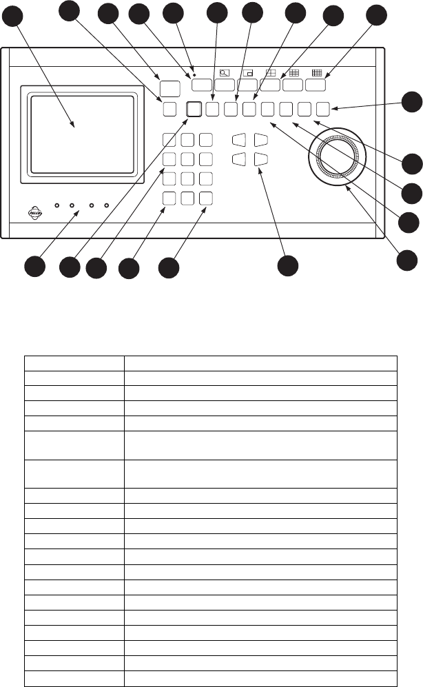
Figure 5. Keyboard Functions
Table E. KBD300V Button Functions
Reference Number Description
1 LED display
2 Shift key
3 Shift key LED
4A-C Sequence keys: Previous, Next, Hold
5Function keys F1, F2, F3 control auxiliaries. With Shift on
they control multiplexer display.
6Functions keys F4, F5 control receiver auxiliaries. With Shift
on they control multiplexer display.
7 Program key
8 Macro sequence key
9 Preset key
10 Pattern key
11 Focus and iris keys
12 Joystick
13 Clear key
14 Camera selection key
15 Keypad (numbers 1 through 0)
16 Acknowledge key
17 Monitor selection key
18 Monitor screen
19 Screen controls for color and brightness
KBD300V
SHIFT
F1 F2 F3 F4 F5
MON ACK PREV NEXT HOLD PATTERN PRESET MACRO PGM
123
456
789
CAM 0 CLEAR
NEAR FAR
OPEN CLOSE
MADE IN U.S.A.
COLOR BRIGHTNESS
-+ -+
18 17 1234
A
4
B
4
C
56
7
8
9
10
12
11
13
1415
16
19

[ 12 ] Pelco Manual C519M-D (7/00)
Table F. Operating Scan Functions with Various Receivers
Function
Receiver Controlling Auto Random Frame Preset Stop
Model Protocol Scan Scan Scan Scan
All 15-bit 97 97 96
Pelco (standard) Preset Preset N/A (2) Preset
Coaxitron®(1) (3) (1)
98 Preset
IRD2024 Extended or 97 N/A N/A 96
ERD2200 Coaxitron 99 Preset Preset Preset
(3)
All Spectra Ext. Coax., 99 97 98 96
All Esprit Serial Pelco Preset Preset Preset N/A Preset
P or D or PTZ
LRD41C Ext. Coax., 99 99 96
(before Serial Pelco Preset Preset N/A N/A Preset
ver. 2.98) P or D (1) (3) (1)
LRD41C Ext. Coax., 99 97 96
(ver 2.98 Serial Pelco Preset Preset N/A N/A Preset
and later) P or D (3)
ERD97P21-U Serial Pelco P N/A 97 Preset 98 Preset N/A 96 Preset
(1) First entry starts random scan, next entry changes to auto scan, etc.
(2) Enter dwell time (5-64 sec.) and press IRIS CLOSE.
(3) Changes to random scan after 30 minutes.
Scanning Functions
Operation of the scanning functions depends on the kind of receiver or pan/tilt mechanism you have and
the operating mode of your keyboard (CM6700 or Direct Mode).
There are four types of scanning functions: auto (moves camera back and forth between stops), random
(moves camera in a random pattern), frame (moves camera back and forth in 10 degree steps), and preset
(sequences camera through all programmed presets, pausing between each).
Operate scans according to Table F.
Programming Limit Stops
Spectra and Esprit can be programmed for scan and manual limit stops.
Program left limit before programming right limit. Locate camera at desired limit. Enter the set code from
Table G. Hold the PRESET key for two seconds. In CM6700 Mode, a label appears on the monitor. Use
F1 and F2 to edit the label, then select SET and press ACK.
To cancel all limit stops, enter 95. Hold the preset key for two seconds. Use the up down tilt keys to move
the pointer to Other. Press IRIS OPEN. Move the pointer to Limit Stops. Press IRIS OPEN. Use the tilt
keys to change limit stops to off. Press IRIS OPEN. Move the pointer to EXIT. Press IRIS OPEN. Move
pointer to exit. Press IRIS OPEN.
Table G. Limit Set Codes
Direction Scan Limit Manual Limit
Left Limit 92 90
Right Limit 93 91

Pelco Manual C519M-D (7/00) [ 13 ]
Zones
The Zone function is available on Esprit and Spectra positioning systems. This function puts a label on
the screen to identify the viewing area. Zones can also be blanked* to prevent viewing while the camera
is positioned in the zone.
Up to eight pan (horizontal) zones can be defined (zones are not affected by tilt or zoom). Higher num-
bered zones take precedence so that if zones overlap, the one with the higher number is in effect. Zone
programming is outlined in Table H.
Table H. Zone Programming Procedure
Step Procedure
1. Set left zone limit. a. Use the joystick to position the camera at the start (left limit) of the
zone.
2. Access zone a. Press 8, followed by the zone number N (N = 1 through 8), and then
programming. F4 to display the zone menu.
3. Define a label. a. Use F1 and F2 to find the characters for each position in the label
HINT: To ease (26 upper case letters, 26 lower case letters and 10 numbers).
future title editing, b. Pan left/right to move between character positions. Continue
start each title with selecting characters until the title is completed (up to 20 characters).
Z(N), where c. Move down to the SET field and press ACK.
N = zone number.
4. Set right zone limit. a. Position camera at the right limit of the zone.
b. Press 8, followed by the zone number, and then F5.
c. To view zone titles go to step 6.
5. Clear zones. a. Press 8, followed by the zone number, and then F4.
b. Move down to the SET field and Press ACK.
NOTE: DO NOT pan right.
c. Press 8, followed by the zone number, and then F5.
6. Tun on zones. a. Press 8, 8, Preset.
7. Blank zones.* a. Press 9, 5 and hold Preset for about 2 seconds to display the Edit
Preset 95 menu.
b. Move down to the SET field and press ACK to display the Camera
menu.
c. Move down to the <Alarms, Zone Blank> field and press Iris Open
to display the Alarms, Zone Blank menu.
d. Move down to the <Zone Blank> field and press Iris Open to display
the Zone Blank menu.
e. Move down to the zone number you wish to blank and press Iris
Open to move the cursor arrow to the zone blanking status value.
f. Pan up to turn blanking on, pan down to turn blanking off.
g. Press Iris Open to accept new status; press Iris Close to cancel.
h. Repeat steps 7e through 7g for each zone you wish to change, then
go to step 7i.
i. Move down to Exit and press Iris Open repeatedly to move up
through the menus and return to the normal display.
* Not available in Esprit systems.

[ 14 ] Pelco Manual C519M-D (7/00)
SPECIFICATIONS
GENERAL
Keyboard Keypad: Mechanical
Display: Red LED, 7-segment, 2 cells
Joystick: 3-axis, vector-solving, with twisting, return-to-center head
Shift Mode Indicator: Green LED
Storage Temperature: -4° to 140°F (-20° to 60°C)
Ambient Operating
Temperature: 14° to 140°F (-10° to 60°C)
Humidity: 10–90% non-condensing
Dimensions: 14.63 (W) x 7.125 (D) x 2.25 (H) inches (37.2 x 18.1 x 5.72 cm)
Weight: 4.3 lb (1.95 kg)
LCD MONITOR
Display Size: 5-inch diagonal (12.7 cm)
Display Method: TFT Active Matrix System
Input Signal: NTSC/PAL
Input Signal Level: 1.0 Vp-p, 75 ohms
Backlight: CCFT Backlight
Power Supply: +12 VDC, 500 mA
Screen Controls: Brightness and color
ELECTRICAL
Input Voltage: +12 VDC @ 1 Amp
Power Consumption: 8 watt
Connector Type: RJ-45, 8-pin, modular (female)
Keyboard Communication, 6700 Mode
Interface: RS-485
Protocol: Pelco ASCII
Baud: 9600
Communication
Parameters: 8 data bits, odd parity, 1 stop bit
Keyboard Communication, Direct Mode
Interface: RS-422
Protocol: Pelco P
Baud: 4800
Communication
Parameters: 8 data bits, no parity, 1 stop bit
MECHANICAL
Tilt Stand: Adds additional 20° viewing angle
(Design and product specifications subject to change without notice.)
Pelco Manual C519M-D (7/00) [ 15 ]
INDEX
A
Acknowledge 10
Auxiliaries 10
C
Clear 10
D
DIP switch 8
F
Firmware version 10
G
Genex multiplexer 3
I
Installation
CM6700 Mode 4
Direct Mode 6
K
Keyboard addresses 8
L
LED 10
Lens Control 9
Limit stops 12
M
Macro sequence 10
Multiplexer displays 10
O
Operation 9
Operational features 3
P
Pan/Tilt 9
Patterns 9
Presets 9
Program 10
Programming 9
R
Regulatory notices 2
Relays 10
Returns 16
S
Safeguards 2
Scanning 12
Select camera 9
Select monitor 9
Sequence 10
Specifications 14
Switch settings 8
W
Warranty 16
Z
Zoom 9
[ 16 ] Pelco Manual C519M-D (7/00)
® Pelco, the Pelco logo, Spectra, Genex, Legacy, Coaxitron, and PelcoVision are registered trademarks of Pelco.
™ Esprit, Spectra II, and Camclosure are trademarks of Pelco. © Copyright 2000, Pelco. All rights reserved.
U.S. Patent No. 411, 530.
WARRANTY AND RETURN INFORMATION
WARRANTY
Pelco will repair or replace, without charge, any merchandise proved defective in material or workmanship for a period of one year after the date
of shipment. Exceptions to this warranty are as noted below:
• Three years on Genex® Series (multiplexers, server, and keyboard).
• Two years on cameras and all standard motorized or fixed focal length lenses.
• Two years on Legacy®, Camclosure™ Camera Systems, CM6700/CM8500/CM9500/CM9750/CM9760 Matrix, PelcoVision®, DF5 Series
and DF8 Fixed Dome products.
• Two years on Spectra® and Esprit™, including when used in continuous motion applications.
• Two years on WW5700 series window wiper (excluding wiper blades).
• Six months on all pan and tilts, scanners or preset lenses used in continuous motion applications (that is, preset scan, tour and auto scan
modes).
Pelco will warrant all replacement parts and repairs for 90 days from the date of Pelco shipment. All goods requiring warranty repair shall be
sent freight prepaid to Pelco, Clovis, California. Repairs made necessary by reason of misuse, alteration, normal wear, or accident are not
covered under this warranty.
Pelco assumes no risk and shall be subject to no liability for damages or loss resulting from the specific use or application made of the Products.
Pelco’s liability for any claim, whether based on breach of contract, negligence, infringement of any rights of any party or product liability,
relating to the Products shall not exceed the price paid by the Dealer to Pelco for such Products. In no event will Pelco be liable for any special,
incidental or consequential damages (including loss of use, loss of profit and claims of third parties) however caused, whether by the negligence
of Pelco or otherwise.
The above warranty provides the Dealer with specific legal rights. The Dealer may also have additional rights, which are subject to variation
from state to state.
If a warranty repair is required, the Dealer must contact Pelco at (800) 289-9100 or (559) 292-1981 to obtain a Repair Authorization number
(RA), and provide the following information:
1. Model and serial number
2. Date of shipment, P.O. number, Sales Order number, or Pelco invoice number
3. Details of the defect or problem
If there is a dispute regarding the warranty of a product which does not fall under the warranty conditions stated above, please include a written
explanation with the product when returned.
Method of return shipment shall be the same or equal to the method by which the item was received by Pelco.
RETURNS
In order to expedite parts returned to the factory for repair or credit, please call the factory at (800) 289-9100 or (559) 292-1981 to obtain an
authorization number (CA number if returned for credit, and RA number if returned for repair). Goods returned for repair or credit should be
clearly identified with the assigned CA/RA number and freight should be prepaid. All merchandise returned for credit may be subject to a 20%
restocking and refurbishing charge.
Ship freight prepaid to: Pelco
3500 Pelco Way
Clovis, CA 93612-5699
REVISION HISTORY
Manual # Date Comments
C519M 12/97 Original version.
C519M-A 1/98 Added installation and operation instructions for Direct Mode. Added operation instructions for
CM6700 Mode.
C519M-B 9/98 Revised manual to show new DIP switch and switch settings.
C519M-C 3/99 Revised manual to show changes to keyboard’s screen, screen display controls, and how the
keyboard is wired for use. Revised, added, and deleted figures throughout the manual. Changed
manual to new format.
6/99 Revised the sequence key definitions. Added paragraphs on how to turn off Spectra scan and
manual limit stops. Added material on programming Spectra features to the Direct Mode
Operation section.
9/99 Corrected step 3 and Figure 9 of Direct Mode Keyboard Installation section. Added patent number.
C519M-D 7/00 Revised format.
