Pelco SM5200 Endura® System Manager User Manual To The F1661102 63ec 4543 8202 Eba497da6ed3
User Manual: Pelco SM5200 to the manual
Open the PDF directly: View PDF ![]() .
.
Page Count: 24
- Endura® SM5200 System Manager
- About the Web Configuration Application
- Logging On to the SM5200
- System Status
- IP Settings
- System Manager Failover Cluster
- System Settings
- DHCP Setup
- LDAP Setup
- Updating the SM5200
CONFIGURATION
C5619M (8/12)
Endura® SM5200
System Manager

2C5619M (8/12)
Contents
About the Web Configuration Application . . . . . . . . . . . . . . . . . . . . . . . . . . . . . . . . . . . . . . . . . . . . . . . . . . . . . . . . . . . . . . . . . . . . . . . . . . . . . . . . . . 4
Endura Application Compatibility . . . . . . . . . . . . . . . . . . . . . . . . . . . . . . . . . . . . . . . . . . . . . . . . . . . . . . . . . . . . . . . . . . . . . . . . . . . . . . . . . . . . . 4
Navigating the Web Interface . . . . . . . . . . . . . . . . . . . . . . . . . . . . . . . . . . . . . . . . . . . . . . . . . . . . . . . . . . . . . . . . . . . . . . . . . . . . . . . . . . . . . . . 4
Saving Configuration Settings . . . . . . . . . . . . . . . . . . . . . . . . . . . . . . . . . . . . . . . . . . . . . . . . . . . . . . . . . . . . . . . . . . . . . . . . . . . . . . . . . . . . . . . 5
System Tools. . . . . . . . . . . . . . . . . . . . . . . . . . . . . . . . . . . . . . . . . . . . . . . . . . . . . . . . . . . . . . . . . . . . . . . . . . . . . . . . . . . . . . . . . . . . . . . . . . . . . 5
Restarting the System . . . . . . . . . . . . . . . . . . . . . . . . . . . . . . . . . . . . . . . . . . . . . . . . . . . . . . . . . . . . . . . . . . . . . . . . . . . . . . . . . . . . . . . . . 5
Restoring Factory Defaults . . . . . . . . . . . . . . . . . . . . . . . . . . . . . . . . . . . . . . . . . . . . . . . . . . . . . . . . . . . . . . . . . . . . . . . . . . . . . . . . . . . . . 5
Logging On to the SM5200 . . . . . . . . . . . . . . . . . . . . . . . . . . . . . . . . . . . . . . . . . . . . . . . . . . . . . . . . . . . . . . . . . . . . . . . . . . . . . . . . . . . . . . . . . . . . . . 6
Changing Your Password . . . . . . . . . . . . . . . . . . . . . . . . . . . . . . . . . . . . . . . . . . . . . . . . . . . . . . . . . . . . . . . . . . . . . . . . . . . . . . . . . . . . . . . . . . . 6
Expiring Passwords . . . . . . . . . . . . . . . . . . . . . . . . . . . . . . . . . . . . . . . . . . . . . . . . . . . . . . . . . . . . . . . . . . . . . . . . . . . . . . . . . . . . . . . . . . . 6
System Status . . . . . . . . . . . . . . . . . . . . . . . . . . . . . . . . . . . . . . . . . . . . . . . . . . . . . . . . . . . . . . . . . . . . . . . . . . . . . . . . . . . . . . . . . . . . . . . . . . . . . . . . 7
Temperature Status . . . . . . . . . . . . . . . . . . . . . . . . . . . . . . . . . . . . . . . . . . . . . . . . . . . . . . . . . . . . . . . . . . . . . . . . . . . . . . . . . . . . . . . . . . . . . . . 7
Video Storage . . . . . . . . . . . . . . . . . . . . . . . . . . . . . . . . . . . . . . . . . . . . . . . . . . . . . . . . . . . . . . . . . . . . . . . . . . . . . . . . . . . . . . . . . . . . . . . . . . . . 8
Fan Status . . . . . . . . . . . . . . . . . . . . . . . . . . . . . . . . . . . . . . . . . . . . . . . . . . . . . . . . . . . . . . . . . . . . . . . . . . . . . . . . . . . . . . . . . . . . . . . . . . . . . . . 8
Disk Status . . . . . . . . . . . . . . . . . . . . . . . . . . . . . . . . . . . . . . . . . . . . . . . . . . . . . . . . . . . . . . . . . . . . . . . . . . . . . . . . . . . . . . . . . . . . . . . . . . . . . . 8
Power Status. . . . . . . . . . . . . . . . . . . . . . . . . . . . . . . . . . . . . . . . . . . . . . . . . . . . . . . . . . . . . . . . . . . . . . . . . . . . . . . . . . . . . . . . . . . . . . . . . . . . . 8
IP Settings . . . . . . . . . . . . . . . . . . . . . . . . . . . . . . . . . . . . . . . . . . . . . . . . . . . . . . . . . . . . . . . . . . . . . . . . . . . . . . . . . . . . . . . . . . . . . . . . . . . . . . . . . . . 9
Configuring the Primary Network Interface . . . . . . . . . . . . . . . . . . . . . . . . . . . . . . . . . . . . . . . . . . . . . . . . . . . . . . . . . . . . . . . . . . . . . . . . . . . . . 9
Configuring the Secondary Network Interface. . . . . . . . . . . . . . . . . . . . . . . . . . . . . . . . . . . . . . . . . . . . . . . . . . . . . . . . . . . . . . . . . . . . . . . . . . 10
System Manager Failover Cluster . . . . . . . . . . . . . . . . . . . . . . . . . . . . . . . . . . . . . . . . . . . . . . . . . . . . . . . . . . . . . . . . . . . . . . . . . . . . . . . . . . . . . . . . 11
Configuring the Failover Cluster IP Address. . . . . . . . . . . . . . . . . . . . . . . . . . . . . . . . . . . . . . . . . . . . . . . . . . . . . . . . . . . . . . . . . . . . . . . . . . . . 11
System Settings. . . . . . . . . . . . . . . . . . . . . . . . . . . . . . . . . . . . . . . . . . . . . . . . . . . . . . . . . . . . . . . . . . . . . . . . . . . . . . . . . . . . . . . . . . . . . . . . . . . . . . 12
Date and Time Configuration . . . . . . . . . . . . . . . . . . . . . . . . . . . . . . . . . . . . . . . . . . . . . . . . . . . . . . . . . . . . . . . . . . . . . . . . . . . . . . . . . . . . . . . 12
Using the System Manager as an Independent Time Server . . . . . . . . . . . . . . . . . . . . . . . . . . . . . . . . . . . . . . . . . . . . . . . . . . . . . . . . . . 13
Synchronizing with an External Time Server. . . . . . . . . . . . . . . . . . . . . . . . . . . . . . . . . . . . . . . . . . . . . . . . . . . . . . . . . . . . . . . . . . . . . . . 13
About Overriding Default DST Settings. . . . . . . . . . . . . . . . . . . . . . . . . . . . . . . . . . . . . . . . . . . . . . . . . . . . . . . . . . . . . . . . . . . . . . . . . . . 13
Pelco Web Viewer Configuration . . . . . . . . . . . . . . . . . . . . . . . . . . . . . . . . . . . . . . . . . . . . . . . . . . . . . . . . . . . . . . . . . . . . . . . . . . . . . . . . . . . . 14
Configuring the Pelco Web Viewer . . . . . . . . . . . . . . . . . . . . . . . . . . . . . . . . . . . . . . . . . . . . . . . . . . . . . . . . . . . . . . . . . . . . . . . . . . . . . . 14
User Permissions for Accessing the Pelco Web Viewer . . . . . . . . . . . . . . . . . . . . . . . . . . . . . . . . . . . . . . . . . . . . . . . . . . . . . . . . . . . . . . 14
Web Server Port Configuration. . . . . . . . . . . . . . . . . . . . . . . . . . . . . . . . . . . . . . . . . . . . . . . . . . . . . . . . . . . . . . . . . . . . . . . . . . . . . . . . . . . . . . 15
Changing the HTTPS Port. . . . . . . . . . . . . . . . . . . . . . . . . . . . . . . . . . . . . . . . . . . . . . . . . . . . . . . . . . . . . . . . . . . . . . . . . . . . . . . . . . . . . . 15
SNMP Configuration. . . . . . . . . . . . . . . . . . . . . . . . . . . . . . . . . . . . . . . . . . . . . . . . . . . . . . . . . . . . . . . . . . . . . . . . . . . . . . . . . . . . . . . . . . . . . . 16
Configuring SNMP v2c. . . . . . . . . . . . . . . . . . . . . . . . . . . . . . . . . . . . . . . . . . . . . . . . . . . . . . . . . . . . . . . . . . . . . . . . . . . . . . . . . . . . . . . . 16
configuring SNMP v3. . . . . . . . . . . . . . . . . . . . . . . . . . . . . . . . . . . . . . . . . . . . . . . . . . . . . . . . . . . . . . . . . . . . . . . . . . . . . . . . . . . . . . . . . 16
DHCP Setup . . . . . . . . . . . . . . . . . . . . . . . . . . . . . . . . . . . . . . . . . . . . . . . . . . . . . . . . . . . . . . . . . . . . . . . . . . . . . . . . . . . . . . . . . . . . . . . . . . . . . . . . . 17
Configuring DHCP Scopes. . . . . . . . . . . . . . . . . . . . . . . . . . . . . . . . . . . . . . . . . . . . . . . . . . . . . . . . . . . . . . . . . . . . . . . . . . . . . . . . . . . . . . . . . . 18
Managing Leases . . . . . . . . . . . . . . . . . . . . . . . . . . . . . . . . . . . . . . . . . . . . . . . . . . . . . . . . . . . . . . . . . . . . . . . . . . . . . . . . . . . . . . . . . . . . . . . . 18
Setting MAC Address Reservations . . . . . . . . . . . . . . . . . . . . . . . . . . . . . . . . . . . . . . . . . . . . . . . . . . . . . . . . . . . . . . . . . . . . . . . . . . . . . . . . . . 18
Deleting MAC Address Reservations . . . . . . . . . . . . . . . . . . . . . . . . . . . . . . . . . . . . . . . . . . . . . . . . . . . . . . . . . . . . . . . . . . . . . . . . . . . . 19
LDAP Setup . . . . . . . . . . . . . . . . . . . . . . . . . . . . . . . . . . . . . . . . . . . . . . . . . . . . . . . . . . . . . . . . . . . . . . . . . . . . . . . . . . . . . . . . . . . . . . . . . . . . . . . . . 20
Disabling Password Expiration . . . . . . . . . . . . . . . . . . . . . . . . . . . . . . . . . . . . . . . . . . . . . . . . . . . . . . . . . . . . . . . . . . . . . . . . . . . . . . . . . . . . . . 21
Configuring LDAP Authentication. . . . . . . . . . . . . . . . . . . . . . . . . . . . . . . . . . . . . . . . . . . . . . . . . . . . . . . . . . . . . . . . . . . . . . . . . . . . . . . . . . . . 21
Configuring Search Settings for Simple LDAP Authentication . . . . . . . . . . . . . . . . . . . . . . . . . . . . . . . . . . . . . . . . . . . . . . . . . . . . . . . . . 21
Configuring Search Settings for Two Stage LDAP Authentication. . . . . . . . . . . . . . . . . . . . . . . . . . . . . . . . . . . . . . . . . . . . . . . . . . . . . . 21
Testing LDAP Search Settings . . . . . . . . . . . . . . . . . . . . . . . . . . . . . . . . . . . . . . . . . . . . . . . . . . . . . . . . . . . . . . . . . . . . . . . . . . . . . . . . . . . . . . 21
Updating the SM5200 . . . . . . . . . . . . . . . . . . . . . . . . . . . . . . . . . . . . . . . . . . . . . . . . . . . . . . . . . . . . . . . . . . . . . . . . . . . . . . . . . . . . . . . . . . . . . . . . . 22

C5619M (8/12) 3
List of Illustrations
1 SM5200 Web Interface . . . . . . . . . . . . . . . . . . . . . . . . . . . . . . . . . . . . . . . . . . . . . . . . . . . . . . . . . . . . . . . . . . . . . . . . . . . . . . . . . . . . . . . . . . . . 4
2 System Tools. . . . . . . . . . . . . . . . . . . . . . . . . . . . . . . . . . . . . . . . . . . . . . . . . . . . . . . . . . . . . . . . . . . . . . . . . . . . . . . . . . . . . . . . . . . . . . . . . . . . . 5
3 System Manager Logon . . . . . . . . . . . . . . . . . . . . . . . . . . . . . . . . . . . . . . . . . . . . . . . . . . . . . . . . . . . . . . . . . . . . . . . . . . . . . . . . . . . . . . . . . . . . 6
4 System Manager Status page . . . . . . . . . . . . . . . . . . . . . . . . . . . . . . . . . . . . . . . . . . . . . . . . . . . . . . . . . . . . . . . . . . . . . . . . . . . . . . . . . . . . . . . 7
5 IP Settings Page . . . . . . . . . . . . . . . . . . . . . . . . . . . . . . . . . . . . . . . . . . . . . . . . . . . . . . . . . . . . . . . . . . . . . . . . . . . . . . . . . . . . . . . . . . . . . . . . . . 9
6 System Page . . . . . . . . . . . . . . . . . . . . . . . . . . . . . . . . . . . . . . . . . . . . . . . . . . . . . . . . . . . . . . . . . . . . . . . . . . . . . . . . . . . . . . . . . . . . . . . . . . . . 12
7 Select System Permissions. . . . . . . . . . . . . . . . . . . . . . . . . . . . . . . . . . . . . . . . . . . . . . . . . . . . . . . . . . . . . . . . . . . . . . . . . . . . . . . . . . . . . . . . . 15
8 DHCP Page . . . . . . . . . . . . . . . . . . . . . . . . . . . . . . . . . . . . . . . . . . . . . . . . . . . . . . . . . . . . . . . . . . . . . . . . . . . . . . . . . . . . . . . . . . . . . . . . . . . . . 17
9 MAC Address Reservations Dialog . . . . . . . . . . . . . . . . . . . . . . . . . . . . . . . . . . . . . . . . . . . . . . . . . . . . . . . . . . . . . . . . . . . . . . . . . . . . . . . . . . 18
10 LDAP Settings Tab . . . . . . . . . . . . . . . . . . . . . . . . . . . . . . . . . . . . . . . . . . . . . . . . . . . . . . . . . . . . . . . . . . . . . . . . . . . . . . . . . . . . . . . . . . . . . . . 20
4C5619M (8/12)
About the Web Configuration Application
The SM5200 is a network appliance that serves as the system management component of the Endura® IP video management system. The
SM5200 Web Configuration Application allows users to quickly and easily configure the SM5200 without installing additional software.
This guide is designed to assist Pelco-certified system administrators with the configuration of the SM5200.
ENDURA APPLICATION COMPATIBILITY
It is recommended that you note the minimum software version requirements for Endura applications comparable with the SM5200. Using
software versions earlier than those listed below may result in unexpected system manager behavior.
•WS5200/WS5070: Version 2.5.3.10286 or later is required to configure operator access to the Pelco Web Viewer.
•Endura Mapping: Version 2.4.0.4959.
•Endura Utilities: Version 2.3.10.3.
NAVIGATING THE WEB INTERFACE
Settings in the SM5200 configuration interface are organized across five pages. Click any of the tabs to navigate pages in the interface.
Additional information and settings are found in the page header, System Information, and System Tools areas of the Web interface.
NOTE: You can click Pelco Web Viewer to exit the configuration application and search, view, or download video clips.
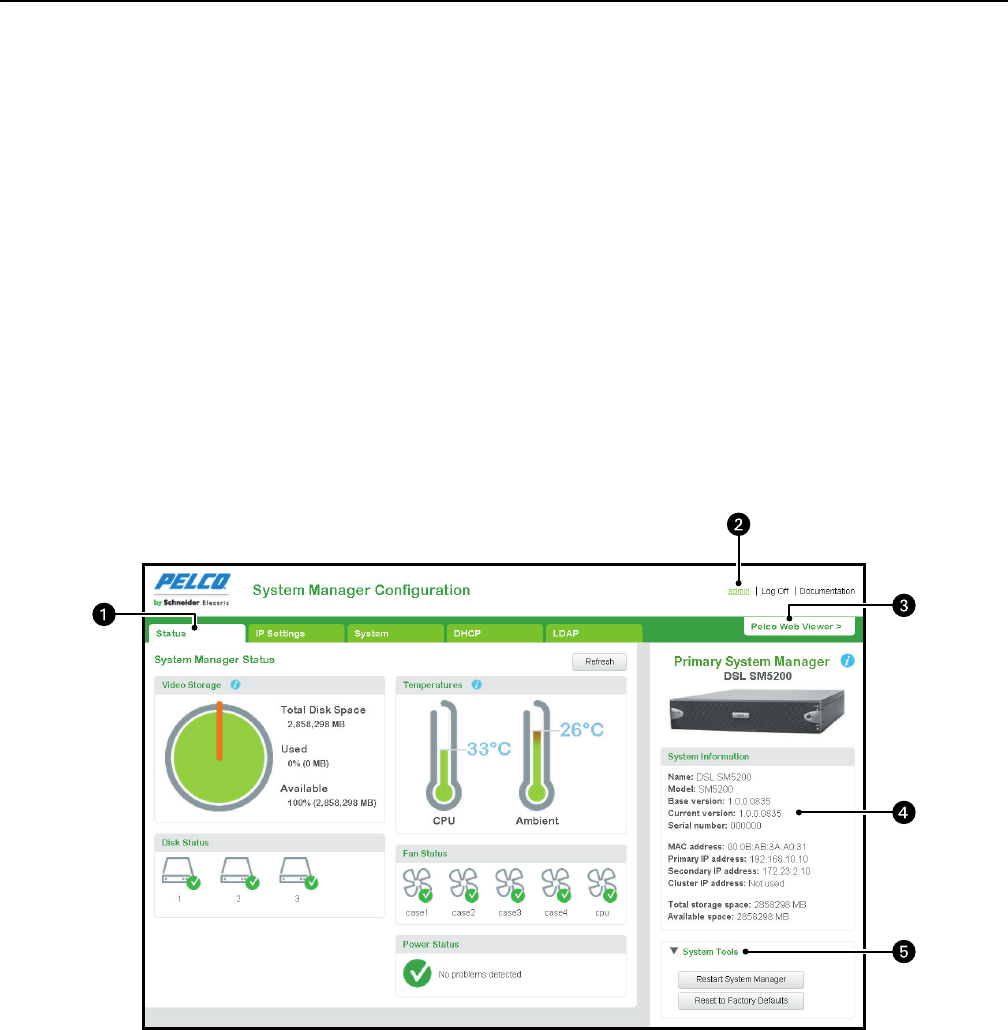
Figure 1. SM5200 Web Interface
ìPage: The SM5200 configuration interface consists of five pages. Click any of the tabs to access a different page.
îSystem Name and Links: This area displays the system name, your User Name, and links to log off or access SM5200 documentation.
ïPelco Web Viewer: Click to exit the configuration interface and view live and recorded video.
ñSystem Information: Displays information about the system manager.
óSystem Tools: Click to reveal maintenance options for the SM5200.
C5619M (8/12) 5
Icons throughout the Web interface will provide you with information about the status of the unit and the validity of your settings.
SAVING CONFIGURATION SETTINGS
Click Save in the lower-right corner of any page to commit your settings to the SM5200. You must click Save before navigating to another page
within the Web interface or you will lose your changes.
Clicking the Cancel button in the lower-right corner will revert all settings on any page to their previously saved values.
NOTE: Some changes to configuration settings cause the system to restart.
SYSTEM TOOLS
The System Tools section of the Web interface contains options for system maintenance. Using any option under System Tools will take the
system manager off line, potentially disrupting your Endura network. Do not use System Tools unless you have configured a failover cluster or
have scheduled maintenance.
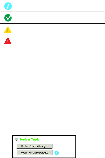
Figure 2. System Tools
RESTARTING THE SYSTEM
NOTES:
• The unit may require a restart following changes to certain system settings. If the unit must restart, the user will receive a prompt to restart
the unit without following the steps below.
• If you have configured a failover cluster, restarting the primary system manager will cause the secondary system manager to take over the
Endura network.
1. Click System Tools.
2. Click Restart System Manager.
3. Confirm your selection.
RESTORING FACTORY DEFAULTS
NOTE: Restoring factory defaults will revert your system manager to an unconfigured state. If you do not have a failover unit configured, your
Endura network will fall off line.
1. Click System Tools.
2. Click Reset to Factory Defaults.
3. Click Reset Configuration to confirm your selection.
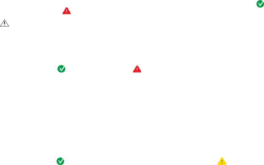
Tooltip: place your mouse pointer over this icon to view
additional information about items within the interface
Indicates a valid setting or a component operating within
a normal, safe range.
Indicates incomplete settings or a component in danger
of failing; monitor closely
Indicates an invalid setting or a system manager
component that has failed; requires immediate attention.
6C5619M (8/12)
Logging On to the SM5200
NOTES:
• The SM5200 Web Configuration Application is compatible with Microsoft® Internet Explorer® versions 9 and later, Mozilla® Firefox®
versions 8 and later, and Google Chrome™ versions 16 and later.
•Only the admin user can access the SM5200 configuration and video viewing pages. All other users only have access to the Pelco
Web Viewer. If you have migrated from an SM5000 environment in which the admin user had been deleted or renamed, you must recreate
the admin user and assign the user the administrative role to access the SM5200 Web configuration interface.
• You might receive a security certificate warning when accessing the system manager from a computer you have not used to access the
system manager before. If this is the case, add an exception in your browser to allow unobstructed access to the system manager. The
process for adding an exception depends on the browser you use to access the system manager.
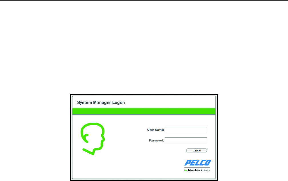
1. Open a Web browser on a computer with network access to the system manager.
2. Type the IP address or hostname of your SM5200 in the navigation bar and press Enter. The default IP address is 192.168.5.10.
Figure 3. System Manager Logon
3. Type your User name and Password in the appropriate boxes.
• The User Name is admin; this is the only user that can access the configuration interface.
• The default Password is admin; if you have migrated from an SM5000 environment with an existing admin user, you will log on using
the password associated with your admin account.
4. Click Log On.
CHANGING YOUR PASSWORD
1. Click your user name in the upper-right corner of the interface. The password change prompt appears.
2. Type your current password in the Old password text box.
3. Type your new password in the New password box.
4. Confirm your new password in the final box.
5. Click Save Password.
NOTE: Users and passwords can be managed from the WS5200 application unless LDAP is enabled.
EXPIRING PASSWORDS
User passwords for the Endura network expire at a rate determined by settings in the WS5200 application. Users receive a password change
reminder upon successful log on attempts within a number days of their password’s expiration date, which is also determined within the
WS5200 application. Clicking Change Password or waiting until the password expires displays the Change Password prompt.
NOTE: If employing an LDAP server for user authentication, you must disable password expiration settings through the WS5200 application
before enabling LDAP.
C5619M (8/12) 7
System Status
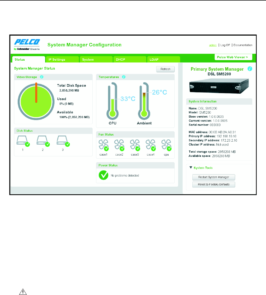
Logging on to the SM5200 as an administrator or clicking the Status tab displays a page detailing the status of the system manager and its
components.
The SM5200’s status does not update in real time. Click Refresh to gather current status information for your system manager.
Figure 4. System Manager Status page
TEMPERATURE STATUS
The two thermometer icons under Temperature display the core CPU temperature and ambient system temperature of the system manager. By
default, temperatures appear in Celsius. Click a thermometer icon to switch between Celsius and Fahrenheit readings.
The thermometers fill in and change color from green to red as the temperature nears the alarm threshold. Alarm thresholds are as follows:
• 72°C (161.6°F) for the CPU
• 35°C (95°F) for ambient temperature
If either temperature reading nears the alarm threshold and the thermometer begins to turn red, take action to determine the cause and alleviate
the problem: improve the rack cooling strategy; check and clean the air filter; or relocate the unit to an environment where an ambient
temperature of 35°C (95°F) or lower can be guaranteed.
WARNING: If either temperature reading crosses the temperature alarm threshold, take action immediately to prevent hardware failure
and potential data loss.
8C5619M (8/12)
VIDEO STORAGE
From the Pelco Web Viewer, users export recorded footage onto the system manager’s integrated storage array for safekeeping and future
access. The SM5200 supports up to 12 TB of video storage.
The video storage pie chart displays the percentages of used and available video storage.
NOTE: Users may free Video Storage by deleting videos from the Export Manager tab in the Pelco Web Viewer.
FAN STATUS
The SM5200 contains five fans. Each fan’s status appears under Fan Status. Fans that are working properly display a green check ; fans that
have failed display a red alarm .
DISK STATUS
The SM5200 contains up to six hard disk drives depending on model. Disk Status displays the status of your system manager’s drives; functioning
drives display a green check ; failed drives display a red alarm .
Disks 1 and 2 are SSDs (Solid State Drives) containing the operating system in a RAID 1 configuration. Replace failed disks in drive bays 1 or 2
with Pelco-provided SSDs immediately to prevent a potential loss of system integrity. After replacing a failed drive, the new drive begins
rebuilding automatically to re-establish RAID 1 parity.
Disks 3 through 6 are HDDs (Hard Disk Drives) used for video storage in JBOD or RAID 5 format, depending on your configuration. RAID 5 ensures
data integrity with one disk failure. Replace failed disks before a second drive fails to prevent data loss.
For more information about the system manager’s drive array, refer to your installation manual.
POWER STATUS
Power Status shows whether the unit is drawing power from a primary AC source or, in the event of a power failure, an uninterruptable power
supply (UPS). A green check indicates that the unit is drawing primary power; a yellow exclamation point indicates that primary power
has failed and the unit is drawing power from an UPS.
It is recommended that you connect your SM5200 to the APC SmartUPS unit to prevent system failures or data loss due to power outages.
WARNING: Fan failures will cause the unit’s internal temperature to rise, which can potentially result in hardware damage. Contact your
Endura system administrator or Pelco Product Support if any of your fans fail.
C5619M (8/12) 9
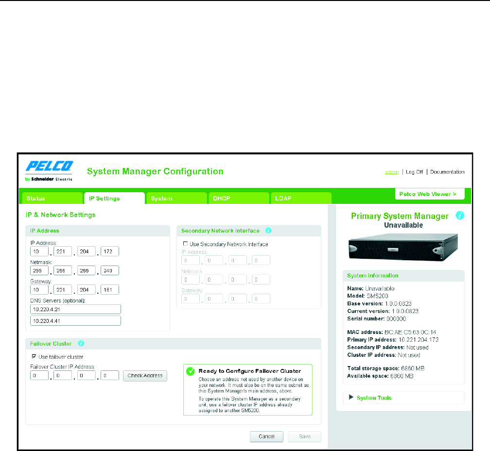
IP Settings
Clicking the IP Settings tab displays settings relating to the configuration of your unit’s network interfaces and the failover cluster. The SM5200
comes equipped with two network interfaces, allowing the unit to act as a gateway to the Endura network.
The Primary network interface: Connects to your private Endura network. This is the interface over which most optional system manager
services operate. You must configure the primary network interface.
The Secondary network interface connects to an alternate network, providing access to Endura from outside the private network. Before
proceeding, ensure that your IT department has reserved and issued the appropriate IP address range for the Endura system.
NOTES:
• Saving changes on the IP Settings page will cause the unit to restart.
• System manager services that normally operate out of the primary network interface (LDAP, NTP, SNMP) can also communicate with
servers over the secondary network interface if the server resides on the same subnet as the secondary network interface.
Figure 5. IP Settings Page
CONFIGURING THE PRIMARY NETWORK INTERFACE
1. Navigate to the IP Settings page.
2. Type the IP address, netmask, and gateway in the appropriate fields.
3. If using DNS servers, type the address or addresses in the DNS Servers (optional) fields.
4. Click Save.
10 C5619M (8/12)
CONFIGURING THE SECONDARY NETWORK INTERFACE
1. Navigate to the IP Settings page.
2. Click the box labeled Use Secondary Network Interface
3. Type the IP address, netmask, and gateway in the appropriate fields.
4. Click Save.

C5619M (8/12) 11
System Manager Failover Cluster
The Failover Cluster option allows a user to designate a redundant, secondary SM5200 to take over Endura system management duties if the
primary SM5200 fails.
The secondary SM5200 duplicates data and settings on the primary unit. When the primary unit fails, the secondary immediately takes over
system manager duties becoming the new primary system manager, which prevents any interruptions in camera accessibility and recorded
footage.
NOTE: The unit in control of the Endura network will act as the primary system manager until it fails or is taken off line and another unit takes
over system management duties.
To configure a secondary SM5200, you must set the failover cluster IP address on two SM5200 units. The failover cluster IP address is a virtual IP
address used for logging on to the SM5200 without needing to be aware as to which SM5200 is currently the primary system manager.
The first system manager to which you assign the failover cluster IP address becomes the primary unit; the second system manager to which you
assign the failover cluster IP address becomes the secondary unit. When connecting system managers to the network in a failover configuration,
bring the primary unit on line first.
CONFIGURING THE FAILOVER CLUSTER IP ADDRESS
1. Log on to the primary system manager. as the admin user
2. Navigate to the IP Settings page.
3. Click the check box marked Use failover cluster.
4. Type the failover cluster IP address; the address must be on the same subnet as the primary network interface.
5. Click Check Address. If you have entered an invalid network address, repeat step 2.
6. Click Save.
7. Log on to the secondary system manager as the admin user:
8. Navigate to the IP Settings page.
9. Click the check box marked Use failover cluster.
10. Type the same IP address entered on the primary system manager in the Failover Cluster IP Address text box.
11. Click Save.
NOTE: If you configure your failover cluster off line, you must bring the primary system manager on line before the secondary system manager
when placing the units on the network.
12 C5619M (8/12)
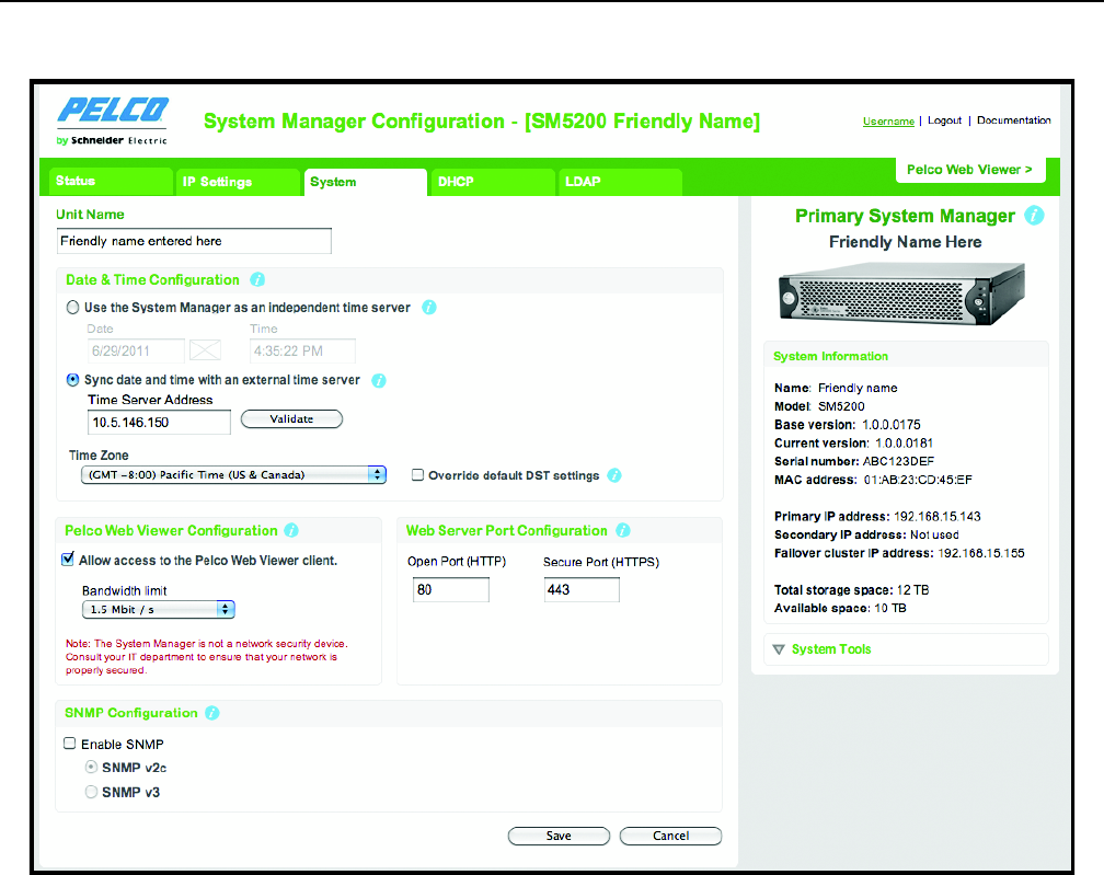
System Settings
Click the System tab to display settings governing date, time, access to the Pelco Web Viewer, and SNMP operation.
Figure 6. System Page
DATE AND TIME CONFIGURATION
The SM5200 acts as a Network Time server (NTP) for the private Endura network. Date and Time Configuration contains date and time settings
affecting both the system manager and all devices on the Endura network.
The system manager provides two options for determining the date and time of your system manager and other Endura devices.
Use the system manager as an independent time server: The system manager applies a manually entered date and time to all Endura
devices.
Sync date and time with an external time server: The system manager applies the date and time determined by an external network time
server to all endura devices. It is recommended that you use an external time server.
NOTES:
• Saving revised date and time settings will cause the unit to restart.
• The SM5200 is built upon standard server hardware and will eventually exhibit time drift. If accurate time is essential, select the “Sync
date and time with an external time server option” and sync the date and time with a calibrated, external time source such as a GPS clock.
C5619M (8/12) 13
USING THE SYSTEM MANAGER AS AN INDEPENDENT TIME SERVER
1. Navigate to the System page
2. Select the “Use the System Manager as an independent time server” option.
3. Enter the current date.
4. Enter the current time.
5. Select your Time zone from the drop down menu.
6. Click Save.
SYNCHRONIZING WITH AN EXTERNAL TIME SERVER
1. Navigate to the System page.
2. Select the “Sync date and time with an external time server” option.
3. Type the IP address or hostname of the external time server in the Time Server Address box.
4. (Optional) Click Validate to test the Time server address. If the address is invalid, check the address of the time server and try again.
NOTE: The system manager can connect to the external time server over the primary network interface or the secondary network interface
if the external time server resides on the same subnet as the secondary network interface.
5. Select your Time Zone from the drop down menu.
6. Click Save.
ABOUT OVERRIDING DEFAULT DST SETTINGS
The system manager automatically applies daylight saving time (DST) settings for your chosen time zone. Only click Override default DST if you
want to alter your time zone’s default DST parameters.
The SM5200 restarts following changes to DST settings. If you have set an invalid DST override setting (for example, a start or end time that
cannot exist due to the time shift), the system manager will not implement the setting after restarting. Check your DST settings following a
restart to ensure that your settings are valid.
OVERRIDING DEFAULT DST SETTINGS
NOTE: Overriding default DST settings will cause the unit to restart.
1. Navigate to the System page.
2. Click the Override default DST settings box
3. Enter the date when daylight savings settings take effect in the Start Date field.
4. Enter the time when daylight savings settings take effect in the Start Time field.
5. Enter the date when daylight savings settings end in the End Date field.
6. Enter the time when daylight savings settings end in the End Date field.
7. Determine the DST Offset.
a. Use the drop-down box to determine whether to add or subtract time during daylight savings time.
b. Enter the number of minutes to offset the time in the Minutes box.
8. Click Save

14 C5619M (8/12)
PELCO WEB VIEWER CONFIGURATION
The Pelco Web Viewer enables users with appropriate permissions to view, search, save, and download video clips from cameras on the Endura
network without installing software. Users can simultaneously access up to 16 live video feeds, at or below the bandwidth limit established by
settings under Pelco Web Viewer Configuration.
NOTES:
• If the “Allow access to the Pelco Web Viewer client” is not checked, the admin user can reach the Pelco Web Viewer over the primary
network interface.
• If “Allow access to the Pelco Web Viewer client” is checked, a user must possess the Remote Access permission to access the Pelco Web
Viewer. The Remote Access permission is enabled for the role belonging to a user or users through the WS5200 application. By default, the
admin user has the Remote Access permission enabled.
CONFIGURING THE PELCO WEB VIEWER
1. Navigate to the System page.
2. Click the “Allow access to the Pelco Web Viewer client” check box.
3. Use the drop-down box to set a bandwidth limit for the Pelco Web Viewer; this bandwidth limit is shared by all users simultaneously
accessing the Pelco Web Viewer.
4. Click Save.
NOTE: In addition to the bandwidth limit, the Pelco Web Viewer is also subject to CPU usage limitations. Attempting to access streams
exceeding available bandwidth or CPU limitations will prevent the streams from displaying.
USER PERMISSIONS FOR ACCESSING THE PELCO WEB VIEWER
By default, only the admin user has access to the Pelco Web Viewer application. To allow another user to access the Pelco Web Viewer, you must
enable the Remote Access permission for a role assigned to that user within the WS5200 application. The Remote Access permission allows a
user access to all the features of the Pelco Web Viewer.
NOTE: Enabling the Remote Access permission for the Pelco Web Viewer requires WS5200 version 2.5.3.10275 or later.
ENABLING USER ACCESS TO THE PELCO WEB VIEWER
1. Open the WS5200 application and log on as an administrator.
2. Click the Setup icon .
3. Click the Roles tab .
4. Select the role belonging to the user or users to whom you want to provide access to the Pelco Web Viewer.
5. Click the System tab, located under Permissions, if it is not already selected.
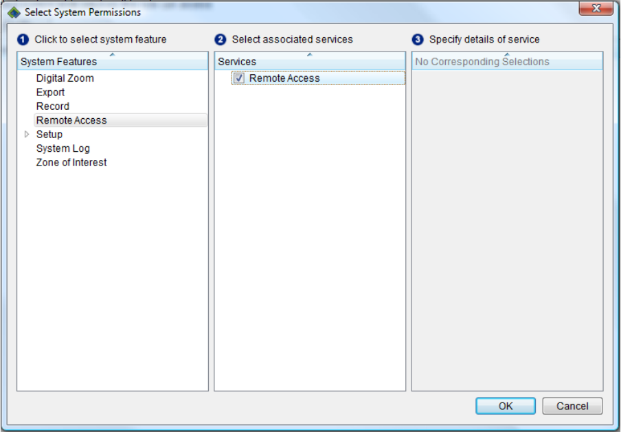
6. Click Modify. The Select System Permissions window appears.
7. Click Remote Access under System Features.
C5619M (8/12) 15
8. Select Remote Access under Services
.
Figure 7. Select System Permissions
9. Click OK.
Users assigned this role can now log on to the Pelco Web Viewer.
WEB SERVER PORT CONFIGURATION
The SM5200’s Web services only accept connections over HTTPS. For added security, administrators can determine the port on which users can
establish a secure communication with the SM5200’s Web interface.
Saving changes to the HTTPS port setting will log the user off of the system manager and redirect the user to the system manager log on page on
the new port. Ensure that any other changes to system manager settings have been saved before changing the HTTPS port, or they will be lost
when the user is logged off and redirected to the system manager log on page.
Do not set the HTTPS port to a port number that is already in use by the system manager. Doing so will cause the Web Configuration Application
to attempt to redirect the user to the log on page on the new port indefinitely. If this occurs, refresh the page to return the configuration
application to normal. For a list of default port numbers used by the SM5200, refer to the Endura Network Design Guide.
CHANGING THE HTTPS PORT
1. Navigate to the System page.
2. Click Edit under Secure Port (HTTPS). The Edit Webviewer Secure Port prompt appears.
3. Type the desired port number for HTTPS communications to the system manager in the Secure Port (HTTPS) field.
4. Click Save.
16 C5619M (8/12)
SNMP CONFIGURATION
The SM5200 supports SNMP v2c and v3 communications. You can gather status information about your system manager by issuing GET requests
or configuring the unit to send traps to a trap manager.
CONFIGURING SNMP V2C
1. Navigate to the System page.
2. Select Enable SNMP
3. Select SNMP v2c.
4. Type the community string used to issue GET requests to the system manager in the Community String field.
5. Type the IP Address or hostname of the trap manager in the Address field under Trap Manager.
NOTE: The system manager must be able to connect to the trap manager over the primary network interface.
6. Type the community string used by the trap manager in the Community String field, under Trap Manager.
7. Click Save.
CONFIGURING SNMP V3
1. Navigate to the System page.
2. Select Enable SNMP.
3. Select SNMP v3.
4. Type the SNMP v3 user name in the SNMP user box.
5. Select the encryption algorithm for authentication from the Authentication drop-down menu. If you choose an authentication method other
than None, type your password in the text box below the selected Authentication algorithm.
6. Select the privacy encryption algorithm from the Privacy drop-down menu. If you choose a privacy method other than None, type a
password in the text box below the selected Privacy encryption method.
7. Type the IP address or hostname of the trap manager in the Trap Manager Address box.
NOTE: The system manager must be able to connect to the trap manager over the primary network interface.
8. Click Save.
C5619M (8/12) 17
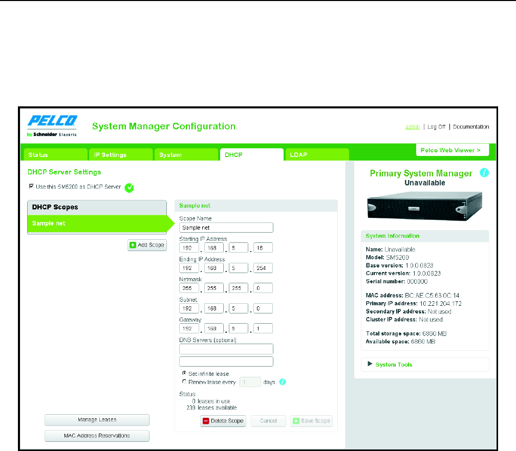
DHCP Setup
In the DHCP tab, you can configure your system manager as a DHCP server for the Endura network. Click the DHCP tab to manage the unit’s DHCP
settings.
NOTES:
• The system manager will only act as a DHCP server on the primary network interface.
• Each DHCP scope must have its own unique name. If you have migrated settings from an SM5000, any DHCP scopes with no name or the
same name as another scope are automatically renamed the GUID of the scope.
Figure 8. DHCP Page
18 C5619M (8/12)
CONFIGURING DHCP SCOPES
1. Navigate to the DHCP page.
2. Select the scope you want to edit. If you need to create a new DHCP scope, click Add Scope.
3. Type a label for the scope in the Scope Name box.
4. Type the scope’s initial IP address in the Starting IP Address field. The Starting IP Address is included in the scope.
5. Type the scope’s final IP address in the Ending IP Address field. The Ending IP Address is included in the scope.
6. Type the netmask, subnet, and gateway in the appropriate boxes.
7. If applicable, type the addresses of up to two DNS servers in the in the DNS server field.
8. Determine the lease length for address assignments.
NOTE: It is recommended that you set an infinite lease; expiring leases will cause gaps in video as addresses are released and renewed.
9. Click Save Scope.
MANAGING LEASES
On the DHCP page, click Manage Leases to display a list of current IP Address assignments.
You can manually release an address by selecting it and clicking Delete Selected.
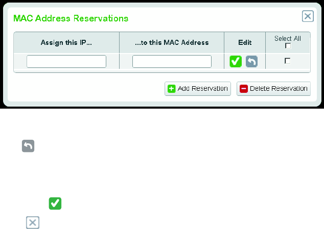
SETTING MAC ADDRESS RESERVATIONS
MAC Address Reservations allow administrators to assign permanent IP addresses to network components requiring a static IP address.
1. Navigate to the DHCP page.
2. Select the scope on which you want to reserve IP addresses.
3. Click MAC Address Reservations.
Figure 9. MAC Address Reservations Dialog
4. Click the Edit Icon to edit an existing reservation or Add Reservation to add an entry to the reservations list.
5. Type the IP Address you want to assign in the “Assign this IP...” field.
6. Type the MAC Address of the device to which the IP address will be assigned in the IP address in the “...to this MAC Address” field.
7. Click the green check icon in the Edit field to save your changes.
8. Click the close icon to return to DHCP Settings when you have finished setting MAC Address Reservations.
C5619M (8/12) 19
DELETING MAC ADDRESS RESERVATIONS
1. Navigate to the DHCP page.
2. Select the scope on which you want to delete MAC address reservations.
3. Click MAC Address Reservations.
4. Select the address or addresses you want to delete. If you want to delete all MAC address reservations, click Select All.
5. Click Delete Reservation.
20 C5619M (8/12)
LDAP Setup
The system manager can connect to and validate user credentials from an Lightweight Directory Access Protocol (LDAP) server allowing for the
integration of the Endura network with single sign-on services. The system manager supports LDAP for Microsoft Active Directory.
The system manager supports the two most common methods for LDAP authentication: simple (single bind) and two-stage bind with a
service account.
Simple (single-bind) authentication associates a user name and password with a distinguished name (DN) to validate user credentials.
The two-stage bind authentication method uses a service DN and a service DN password to establish the initial bind with the LDAP server. Upon
a successful initial bind, a search is performed using the base DN, the first key from the Search Attributes field, and the user name. If the user’s
information is found, the second bind is performed using the DN to authenticate user credentials.
NOTES:
• The system manager can connect to the LDAP server over the primary network interface or the secondary network interface if the LDAP
server resides on the same subnet as the secondary network interface.
• You must disable password expiration from the WS5200 application before enabling LDAP.
• If LDAP is enabled and you need to change the password for the admin user, you must do so through the Web Configuration Application.
• A User Name must exist in both the LDAP directory and Endura users list for successful user validation; in an LDAP validated system, user
permissions are still managed from the Endura network. Refer to your WS5200 software manual for more information about configuring
users, roles, and permissions.
• This guide provides instructions for configuring simple or two-stage bind LDAP authentication schemes; however, the system manager may
support additional LDAP authentication schemes.
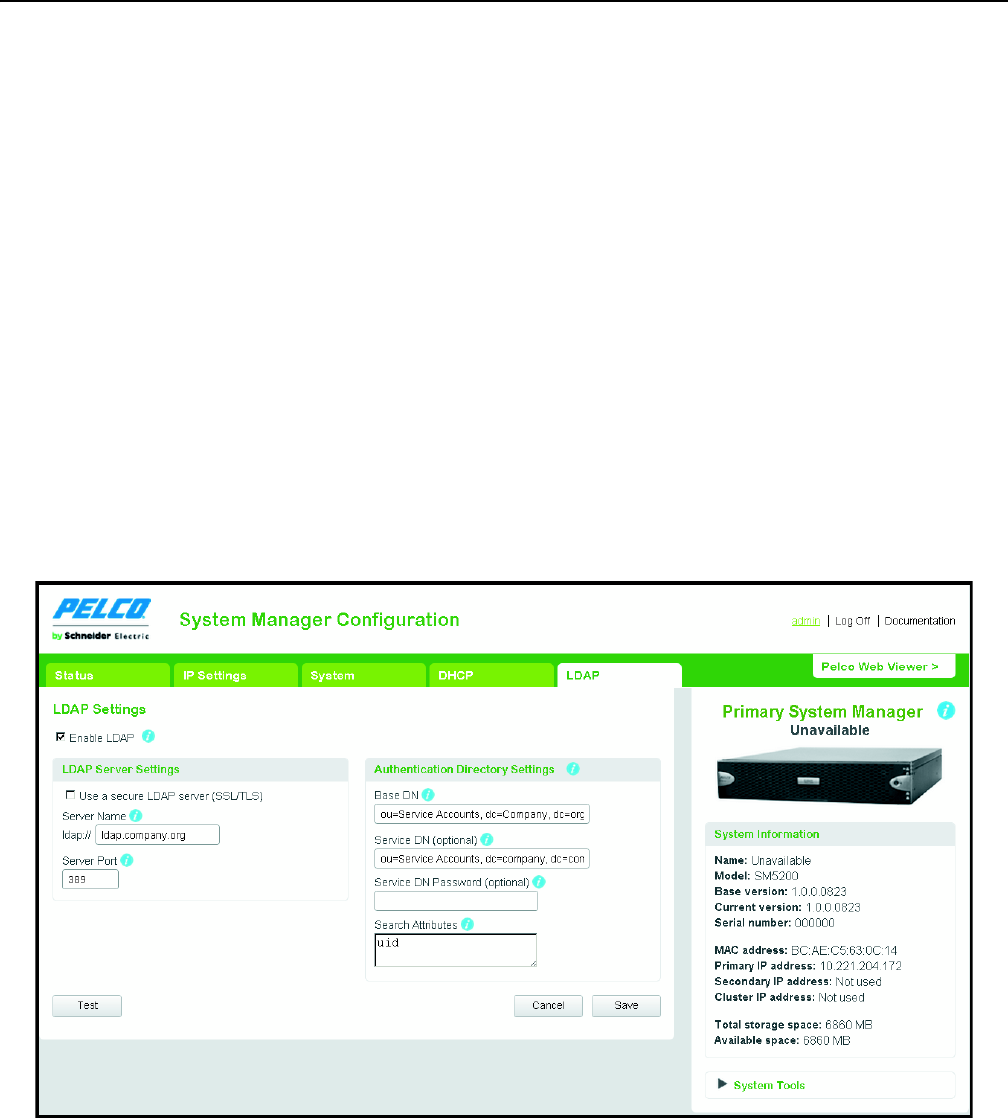
Click the LDAP tab to access your system manager’s LDAP settings.
Figure 10. LDAP Settings Tab
C5619M (8/12) 21
DISABLING PASSWORD EXPIRATION
You must disable password expiration before enabling LDAP to prevent user management conflicts between the system manager and the
LDAP server.
1. Log on to the WS5200 application as an administrator.
2. Click the System Configuration tab if it is not already selected.
3. Scroll down to Password Settings, and click Off.
4. Click Apply.
You can now configure LDAP authentication.
CONFIGURING LDAP AUTHENTICATION
1. Navigate to the LDAP page.
2. Select Enable LDAP
3. Type the hostname or IP address of the LDAP server in the Server name field.
4. Edit the Server port field if the LDAP server is not on the default port (389).
5. Configure Search Settings for your LDAP server.
6. Click Save.
CONFIGURING SEARCH SETTINGS FOR SIMPLE LDAP AUTHENTICATION
Configuring search settings for simple LDAP authentication only requires the Base DN and the Search Attributes fields. Leave other fields blank.
When inputting multiple entries in a field, separate entries with commas.
1. Type a distinguished name (DN) that will be combined with a user attribute key and value pair in the Base DN field.
2. Type an attribute key name that is combined with the User Name attribute in the Search Attributes field.
CONFIGURING SEARCH SETTINGS FOR TWO STAGE LDAP AUTHENTICATION
Configuring search settings for two-stage LDAP authentication requires all fields. When typing multiple entries in a field, separate entries with
commas.
1. Type the distinguished name (DN) that acts as the basis for user searches by User Name in the Base DN field.
2. Type a fully qualified DN associated with a service account that will bind with the LDAP server and perform user searches in the Service DN
field.
3. Type the password that allows the service DN to bind with the LDAP server in the Service DN Password field.
4. Type the two attribute keys that are combined with the User Name attribute; separate the two keys with a comma.
• The first key identifies the attribute containing the user name.
• The second key identifies the fully qualified DN used for the second bind and credential validation.
TESTING LDAP SEARCH SETTINGS
1. Navigate to the LDAP page.
2. Click Test.
3. Input the User Name and Password for a valid user in the LDAP database.
4. Click Test Connection.
If the connection passes, your LDAP configuration is valid. If the connection fails, verify your LDAP Server Settings and Search Settings and
try again.

22 C5619M (8/12)
Updating the SM5200
Updates for the SM5200 are applied through the WS5200 application or Endura Utilities; you cannot apply an update using the Web
configuration application.
NOTE: Applying a software update will cause the unit to restart. Do not update the system manager unless you have planned or scheduled
system maintenance.
If you have two SM5200 units in a failover configuration, the update process automatically accounts for both primary and secondary system
managers. The update is first applied to the secondary system manager, and then to the primary system manager. Because the update process
requires a restart, a failover occurs when the primary unit restarts to apply the update.
1. Locate the software update on productsupport.pelco.com.
2. Download the software update to C:\Program Files\Pelco\Endura\GUI\Update.
3. Open the WS5200 application.
4. Click the setup icon .
5. Click the Update Software tab .
6. Select the SM5200. You may wish to use the filters at the top of the device list to find the unit.
7. Click the “Select software package” option. A selection dialog box appears.
8. Select the file containing the updated software in the C:\Program Files\Pelco\Endura\GUI\Update directory.
9. Click Update.
The progress bar at the bottom of the screen tracks the update procedure. When the update is complete, a dialog appears informing you of the
success or failure of the update.

PRODUCT WARRANTY AND RETURN INFORMATION
WARRANTY
Pelco will repair or replace, without charge, any merchandise proved defective in
material or workmanship for a period of one year after the date of shipment.
Exceptions to this warranty are as noted below:
• Five years:
– Fiber optic products
– Unshielded Twisted Pair (UTP) transmission products
– CC3701H-2, CC3701H-2X, CC3751H-2, CC3651H-2X, MC3651H-2, and
MC3651H-2X camera models
• Three years:
– FD Series and BU Series analog camera models
– Fixed network cameras and network dome cameras with Sarix® technology
– Sarix thermal imaging products (TI and ESTI Series)
– Fixed analog camera models (C20 Series, CCC1390H Series, C10DN Series,
and C10CH Series)
– EH1500 Series enclosures
– Spectra® IV products (including Spectra IV IP)
– Spectra HD dome products
– Camclosure® IS Series integrated camera systems
– DX Series video recorders (except DX9000 Series which is covered for a
period of one year), DVR5100 Series digital video recorders, Digital Sentry®
Series hardware products, DVX Series digital video recorders, and NVR300
Series network video recorders
– Endura® Series distributed network-based video products
– Genex® Series products (multiplexers, server, and keyboard)
– PMCL200/300/400 Series LCD monitors
– PMCL5xxF Series and PMCL5xxNB Series LCD monitors
• Two years:
– Standard varifocal, fixed focal, and motorized zoom lenses
– DF5/DF8 Series fixed dome products
– Legacy® Series integrated positioning systems
– Spectra III™, Spectra Mini, Spectra Mini IP, Esprit®, ExSite®, ExSite IP, and
PS20 scanners, including when used in continuous motion applications
– Esprit Ti and TI2500 Series thermal imaging products
– Esprit and WW5700 Series window wiper (excluding wiper blades)
– CM6700/CM6800/CM9700 Series matrix
– Digital Light Processing (DLP®) displays (except lamp and color wheel). The
lamp and color wheel will be covered for a period of 90 days. The air filter is
not covered under warranty.
•Six months:
– All pan and tilts, scanners, or preset lenses used in continuous motion
applications (preset scan, tour, and auto scan modes)
Pelco will warrant all replacement parts and repairs for 90 days from the date of
Pelco shipment. All goods requiring warranty repair shall be sent freight prepaid
to a Pelco designated location. Repairs made necessary by reason of misuse,
alteration, normal wear, or accident are not covered under this warranty.
Pelco assumes no risk and shall be subject to no liability for damages or loss
resulting from the specific use or application made of the Products. Pelco’s liability
for any claim, whether based on breach of contract, negligence, infringement of
any rights of any party or product liability, relating to the Products shall not exceed
the price paid by the Dealer to Pelco for such Products. In no event will Pelco be
liable for any special, incidental, or consequential damages (including loss of use,
loss of profit, and claims of third parties) however caused, whether by the
negligence of Pelco or otherwise.
The above warranty provides the Dealer with specific legal rights. The Dealer may
also have additional rights, which are subject to variation from state to state.
If a warranty repair is required, the Dealer must contact Pelco at (800) 289-9100 or
(559) 292-1981 to obtain a Repair Authorization number (RA), and provide the
following information:
1. Model and serial number
2. Date of shipment, P.O. number, sales order number, or Pelco invoice number
3. Details of the defect or problem
If there is a dispute regarding the warranty of a product that does not fall under
the warranty conditions stated above, please include a written explanation with
the product when returned.
Method of return shipment shall be the same or equal to the method by which the
item was received by Pelco.
RETURNS
To expedite parts returned for repair or credit, please call Pelco at (800) 289-9100
or (559) 292-1981 to obtain an authorization number (CA number if returned for
credit, and RA number if returned for repair) and designated return location.
All merchandise returned for credit may be subject to a 20 percent restocking and
refurbishing charge.
Goods returned for repair or credit should be clearly identified with the assigned
CA or RA number and freight should be prepaid.
The materials used in the manufacture of this document and its components are compliant to the requirements of Directive 2002/95/EC.
This equipment contains electrical or electronic components that must be recycled properly to comply with Directive 2002/96/EC of the European Union
regarding the disposal of waste electrical and electronic equipment (WEEE). Contact your local dealer for procedures for recycling this equipment.
Revised 1-12-12
REVISION HISTORY
Manual # Date Comments
C5619M 8/12 Original version.
Pelco, the Pelco logo, and other trademarks associated with Pelco products referred to in this publication are trademarks of Pelco, Inc. or its affiliates. © Copyright 2012, Pelco, Inc.
ONVIF and the ONVIF logo are trademarks of ONVIF Inc. All other product names and services are the property of their respective companies. All rights reserved.
Product specifications and availability are subject to change without notice.