Pentair Aquatic Systems EASYTOUCH2A EasyTouch Wireless 2 Handheld User Manual 520688 Rev E 10 04 11
Pentair Aquatic Systems EasyTouch Wireless 2 Handheld 520688 Rev E 10 04 11
User Manual
EasyTouch® Pool and Spa
Control System
Wireless Control Panel
IMPORTANT SAFETY INSTRUCTIONS
READ AND FOLLOW ALL INSTRUCTIONS
SAVE THESE INSTRUCTIONS
Installation and
User’s Guide

© 2012 Pentair Water Pool and Spa, Inc. All rights reserved
This document is subject to change without notice
1620 Hawkins Ave., Sanford, NC 27330 • (800) 831-7133 • (919) 566-8000
10951 West Los Angeles Ave., Moorpark, CA 93021 • (800) 831-7133 • (805) 553-5000
EasyTouch®, IntelliChlor®, IntelliChem™, IntelliFlo®, QuickTouch®, MagicStream®, IntelliBrite®,
SAm®, SAL®, FIBER
works®,
ThermalFlo® and Pentair Water Pool and Spa® are trademarks and/or
registered trademarks of Pentair Water Pool and Spa, Inc. and/or its affiliated companies in the United
States and/or other countries. Unless noted, names and brands of others that may be used in this
document are not used to indicate an affiliation or endorsement between the proprietors of these names
and brands and Pentair Water Pool and Spa, Inc. Those names and brands may be the trademarks or
registered trademarks of those parties or others.
P/N 520688 Rev & - 0//1
Download a PDF version of this manual to your computer from:
http://www.pentairpool.com/pdfs/EasyTouchWirelessControlUG.pdf
i
EasyTouch Wireless Control Panel Installation and User’s Guide
Contents
IMPORTANT WARNING AND SAFETY INSTRUCTIONS .................................................................. iii
EasyTouch Wireless Control Panel Kit Contents .............................................................................. v
Related Manuals .............................................................................................................................. v
EasyTouch Accessories ................................................................................................................... v
Technical Support ............................................................................................................................. vi
Section 1: EasyTouch Wireless Control Panel Overview ........................................................... 1
Introduction ...................................................................................................................................... 1
Operating EasyTouch ....................................................................................................................... 1
EasyTouch Systems ........................................................................................................................ 1
EasyTouch Wireless Control Panel Overview .................................................................................... 2
EasyTouch Wireless Control Panel Buttons ..................................................................................... 3
EasyTouch Wireless Control Panel Display ...................................................................................... 5
Battery Overview ............................................................................................................................... 6
Checking the battery charge ........................................................................................................ 6
Power Save Options ..................................................................................................................... 7
Backlight Options ........................................................................................................................ 7
Installing Batteries ....................................................................................................................... 7
Quick Start - Pool and Spa Operations (Shared Equipment) ............................................................. 9
Heating the Spa/Pool ................................................................................................................... 9
Schedule start and stop times for equipment ............................................................................... 10
Controlling Lights ......................................................................................................................... 10
Setting up the EasyTouch wireless control panel .............................................................................. 11
EasyTouch Menus ............................................................................................................................ 12
Section 2 - Setting up the EasyTouch System ............................................................................. 13
EasyTouch Menus (Continued) ......................................................................................................... 14
Main Screen ..................................................................................................................................... 14
Feature Circuits Menu ...................................................................................................................... 15
Lights Menu ..................................................................................................................................... 16
The Color Swim and Color Set Lighting Features.......................................................................... 16
Setting up Lights .............................................................................................................................. 17
Assign the Circuit Name and Function ........................................................................................ 17
Setting up IntelliBrite Light Circuits .............................................................................................. 18
Lights Menu ..................................................................................................................................... 18
Modes (IntelliBrite Color light shows, Color Swim, Color Set) ....................................................... 18
Modes (Color Swim) ..................................................................................................................... 18
Modes (Color Set) ........................................................................................................................ 19
Colors .......................................................................................................................................... 19
Hold/Recall .................................................................................................................................. 19
All On / All Off (Lights Menu) ........................................................................................................ 19
Sync ............................................................................................................................................. 19
Config ........................................................................................................................................... 20
Setting up SAM, SAL, PG2000, Color Wheel Lights ........................................................................ 20
Setting up MagicStream Laminars .................................................................................................... 21
Using the MagicStream Laminars Features ...................................................................................... 22
Heat Menu ....................................................................................................................................... 23
Pool Temp/Src ............................................................................................................................. 23
Spa Temp/Src .............................................................................................................................. 23
Delay Cancel Menu .......................................................................................................................... 24
Schedules Menu .............................................................................................................................. 25
Schedule your spa/pool to turn on ................................................................................................ 26
Using the Once Only feature ........................................................................................................ 27
Using the Egg Timer (countdown) Feature .................................................................................... 28
Settings Menu: Clock ....................................................................................................................... 29
Settings Menu: IntelliFlo ................................................................................................................... 29
ii
EasyTouch Wireless Control Panel Installation and User’s Guide
Contents
Settings Menu: IntelliFlo (VS and VSF +SVRS) ............................................................................... 30
Settings Menu: IntelliFlo (VF) ........................................................................................................... 32
Settings Menu: IntelliChlor ................................................................................................................ 33
Settings Menu: IntelliChem .............................................................................................................. 36
Settings Menu: Heat Pump COM (UltraTemp) .................................................................................. 38
Settings Menu: Circuit Names .......................................................................................................... 39
Hi-Temp/Lo-Temp Controls for Single Body System...................................................................... 39
EasyTouch Circuit Names (Complete List) ....................................................................................... 40
Settings Menu: Circuit Functions ..................................................................................................... 41
Freeze Protection ........................................................................................................................ 41
Preset Circuit Function Names (Complete List) ............................................................................ 42
Settings Menu: Custom Names........................................................................................................ 43
Settings Menu: Valves ...................................................................................................................... 43
Settings Menu: 2-Speed Pump ......................................................................................................... 44
Settings Menu: Solar ........................................................................................................................ 44
Settings Menu: Delays ..................................................................................................................... 45
Settings Menu: F° / C° (Fahrenheit/Celsius) .....................................................................................46
Settings Menu: iS4 Spa-Side Remote Controller ............................................................................... 46
Settings Menu: iS10 Spa-Side Remote Controller ............................................................................. 47
Settings Menu: iSx Pump Crtl .......................................................................................................... 48
Settings Menu: QuickTouch (QT4) Wireless Remote ........................................................................ 49
Settings Menu: Man Heat (Off/On).................................................................................................... 50
Settings Menu: Calibration ............................................................................................................... 50
Settings Menu: Erase EEPROM (Erase System Memory) ............................................................... 51
Settings Menu: Set Password .......................................................................................................... 51
Settings Menu: Backlight ................................................................................................................. 52
Settings Menu: Power Save ............................................................................................................. 52
Settings Menu: Wireless Addr .......................................................................................................... 53
Spa Side [Off/On] ............................................................................................................................. 54
Diagnostics Menu: Software Rev ...................................................................................................... 54
Diagnostics Menu: Bootloader Rev ................................................................................................... 55
Diagnostics Menu: Self Test ............................................................................................................. 55
Diagnostics Menu: Chlorinator .......................................................................................................... 55
Diagnostics Menu: Water Temp ........................................................................................................ 55
Diagnostics Menu: Solar Temp ......................................................................................................... 55
Diagnostics Menu: Air Temp ............................................................................................................. 56
Diagnostics Menu: Cir Name: [Off/On] .............................................................................................. 56
Diagnostics Menu: Reset System .................................................................................................... 56
Diagnostics Menu: Flash Update ...................................................................................................... 56
Section 3 - Troubleshooting .......................................................................................................... 57
Frequently Asked Questions (FAQ) .............................................................................................. 57
EasyTouch Error Messages ......................................................................................................... 58
Self Test Error Codes ............................................................................................................... 58
Error Code Table ...................................................................................................................... 58
Maximum Programs Exceeded ................................................................................................ 59
IntelliChlor Error Messages .......................................................................................................... 59
System Problem Diagnosis .......................................................................................................... 60
EasyTouch System Wiring Diagram .............................................................................................62
First Time System Start-Up .......................................................................................................... 63
Wiring a ThermalFlo Heat Pump to an EasyTouch Control System .................................................. 64
Section 4 - EasyTouch Transceiver Installation ........................................................................... 65
Glossary .......................................................................................................................................... 69
iii
EasyTouch Wireless Control Panel Installation and User’s Guide
IMPORTANT WARNING AND SAFETY INSTRUCTIONS
II
Important Notice:
Attention Installer: This manual contains important information about the installation, operation
and safe use of this product. This information should be given to the owner and/or operator of this equipment.
WARNING - Before installing this product, read and follow all warning notices and instructions which are
included. Failure to follow safety warnings and instructions can result in severe injury, death, or property
damage. Call (800) 831-7133 for additional free copies of these instructions.
WARNING - Water temperature in excess of 100 degrees Fahrenheit may be hazardous to your health.
Prolonged immersion in hot water may induce hyperthermia. Hyperthermia occurs when the internal temperature
of the body reaches a level several degrees above normal body temperature of 98.6° F (37° C). The symptoms
of hyperthermia include drowsiness, lethargy, dizziness, fainting, and an increase in the internal temperature of
the body.
The effects of hyperthermia include: 1) Unawareness of impending danger. 2) Failure to perceive heat. 3) Failure
to recognize the need to leave the spa. 4) Physical inability to exit the spa. 5) Fetal damage in pregnant women.
6) Unconsciousness resulting in danger of drowning.
WARNING - To reduce the risk of injury, do not permit children to use this product unless they are closely
supervised at all times.
WARNING - The use of alcohol, drugs, or medication can greatly increase the risk of fatal
hyperthermia in hot tubs and spas.
WARNING - Control System is intended to control heaters with built-in high limit circuits ONLY. Failure to do
so may cause property damage or personal injury.
WARNING - Do not use this product to control an automatic pool cover. Swimmers may become entrapped
underneath the cover.
WARNING - For units intended for use in other than single-family dwellings, a clearly labeled emergency
switch shall be provided as part of the installation. The switch shall be readily accessible to the occupants and
shall be installed at least 10 feet (3.05 m) away, adjacent to, and within sight of, the unit.
CAUTION - Except for listed spa-side remote controls, install a minimum of five (5) feet from the inside wall
of the pool and spa.
Head
Body
Upper
Arm
Upper
Arm
Leg Joint
Leg Joint
Leg Joint
Leg Joint
Head
Body
Upper
Arm
Leg Joint
Leg Joint
Leg Joint
Leg Joint
Two Speed Pump Controls Notice (Title 20 Compliance)
Please read the following important Safety Instructions (See page 44 for pump speed setup)
When using two-speed pumps manufactured on or after January 1, 2008, the pump’s default
circulation speed MUST be set to the LOWEST SPEED, with a high speed override capability being
for a temporary period not to exceed one normal cycle, or two hours, whichever is less.
iv
EasyTouch Wireless Control Panel Installation and User’s Guide
IMPORTANT WARNING AND SAFETY INSTRUCTIONS
General Installation Information
1. All work must be performed by a licensed electrician, and must conform to all national, state, and local
codes.
2. Install to provide drainage of compartment for electrical components.
3. If this system is used to control underwater lighting fixtures, a ground-fault circuit interrupter (GFCI)
must be provided for these fixtures. Conductors on the load side of the ground-fault circuit-interrupter
shall not occupy conduit, junction boxes or enclosures containing other conductors unless such
conductors are also protected by a ground-fault circuit-interrupter. Refer to local codes for details.
4. A terminal bar stamped is located inside the supply terminal box. To reduce the risk of electric
shock, this terminal must be connected to the grounding means provided in the electric supply service
panel with a continuous copper wire equivalent in size to the circuit conductors supplying this
equipment (no smaller than 12 AWG or 3.3 mm). The bonding lug(s) provided on this unit are intended
to connect a minimum of one No. 8 AWG for US installation and two No. 6 AWG for Canadian
installations solid copper conductor between this unit and any metal equipment, metal enclosures or
electrical equipment, metal water pipe, or conduit within 5 feet (1.5 m) of the unit.
5. The electrical supply for this product must include a suitably rated switch or circuit breaker to open all
ungrounded supply conductors to comply with Section 422-20 of the National Electrical Code, ANSI/
NFPA 70.1987. The disconnecting means must be readily accessible to the tub occupant but installed
at least 10 ft. (3.05 m) from the inside wall of the pool.
6. Supply conductor must be sized to support all loads. Maximum supply conductor current must be 125
Amps at 125 VAC.
RF Exposure Requirements: The antenna(s) used for this device must be installed to provide a separation
distance of at least 7.0 inches (20 cm) from all persons and must not be co-located or operating in conjunction with
any other antenna or transmitter.
L'antenne (s) utilisé pour cet appareil doit être installé pour fournir une distance de séparation d'au moins (20 cm) à
partir de toutes les personnes et ne doit pas être co-localisés ou fonctionner en conjonction avec une autre antenne
ou un autre émetteur.

v
EasyTouch Wireless Control Panel Installation and User’s Guide
IMPORTANT WARNING AND SAFETY INSTRUCTIONS
FCC Standard - 47 CFR Part 15, Subpart C (Section 15.247). This version is limited to chapter 1 to chapter 11 by
specified firmware controlled in the U.S.A.
Instruction to user - This equipment has been tested and found to comply with the limits for a Class B digital device,
pursuant to Part 15 of the FCC Rules. These limits are designed to provide reasonable protection against harmful
interference in a residential installation. This equipment generates, uses and can radiate radio frequency energy
and, if not installed and used in accordance with the instructions, may cause harmful interference to radio
communications. However, there is no guarantee that interference will not occur in a particular installation. If this
equipment does cause harmful interference to radio or television reception, which can be determined by turning the
equipment off and on, the user is encouraged to try to correct the interference by one or more of the following
measures:
• Reorient or relocate the receiving antenna.
• Increase the separation between the equipment and receiver.
• Connect the equipment into an outlet on a circuit different from that to which the receiver is connected.
• Consult the dealer or an experienced radio/TV technician for help.
Note: In order to maintain compliance with FCC regulations, shielded cables must be used with this equipment.
Operation with non-approved equipment or unshielded cables is likely to result in interference to radio and TV
reception. The user is cautioned that changes and modifications made to the equipment without the approval of the
manufacturer could void the user’s authority to operate this equipment.
Canada - Industry Canada (IC) Regulatory Notice: - This device complies with RSS210 of Industry Canada. (1999).
Under Industry Canada regulations, this radio transmitter may only operate using an antenna of a type and
maximum (or lesser) gain approved for the transmitter by Industry Canada. To reduce potential radio interference to
other users, the antenna type and its gain should be so chosen that the equivalent isotropically radiated power
(e.i.r.p.) is not more than that necessary for successful communication. This device complies with Industry Canada
licence-exempt RSS standard(s). Operation is subject to the following two conditions: (1) this device may not cause
interference, and (2) this device must accept any interference, including interference that may cause undesired
operation of the device.
Conformément à la réglementation d'Industrie Canada, le présent émetteur radio peut fonctionner avec une
antenne d'un type et d'un gain maximal (ou inférieur) approuvé pour l'émetteur par Industrie Canada. Dans le but de
réduire les risques de brouillage radioélectrique à l'intention des autres utilisateurs, il faut choisir le type d'antenne
et son gain de sorte que la puissance isotrope rayonnée équivalente (p.i.r.e.) ne dépasse pas l'intensité nécessaire
à l'établissement d'une communication satisfaisante. Le présent appareil est conforme aux CNR d'Industrie Canada
applicables aux appareils radio exempts de licence. L'exploitation est autorisée aux deux conditions suivantes : (1)
l'appareil ne doit pas produire de brouillage, et (2) l'utilisateur de l'appareil doit accepter tout brouillage
radioélectrique subi, même si le brouillage est susceptible d'en compromettre le fonctionnement.
vi
EasyTouch Wireless Control Panel Installation and User’s Guide
EasyTouch Wireless Control Panel Kit Contents
The following items are included in the EasyTouch wireless control panel kit. If any items are missing please
contact Pentair Technical Support (see page vi).
• EasyTouch wireless control panel
• Four AA-size alkaline batteries
• EasyTouch transceiver module (with four plastic anchors and mounting screws)
• EasyTouch Wireless Control Panel User’s and Installation Guide (this manual)
Related Manuals
• EasyTouch 8 and 4 Pool and Spa Control System User’s Guide (P/N 520584)
• EasyTouch Indoor Control Panel User’s and Installation (P/N 520617)
• EasyTouch 8 and 4 Installation Guide (P/N 520583)
EasyTouch Accessories
EasyTouch Indoor Control Panel, 4 Circuits (P/N 520548)
EasyTouch Indoor Control Panel, 8 Circuits (P/N 520549)
EasyTouch Wireless Control Panel, 4 circuits (P/N 520546)
EasyTouch Wireless Control Panel, 8 circuits (P/N 520547)
iS4 Four-Function Spa-Side remote, 150 ft. cable (P/N 520094)
iS10 Ten-Function Spa-Side remote, 150 ft. cable (P/N 520149)
QuickTouch four-function wireless remote kit with transceiver assembly (P/N 520148)
IntelliChlor Acid Cleaning Kit (P/N 520670)
IntelliChlor Spacer pass-through cell for new pool start-up (P/N 520588)
IntelliChem: (P/N 521357)
(no pump)
(P/N 521356)
(one pump)
(P/N 521355)
(two pump)
Technical Support
Contact Technical Support at:
Sanford, North Carolina (8 A.M. to 5 P.M.)
Phone: (800) 831-7133
Fax: (919) 566-8920
Moorpark, California (8 A.M. to 5 P.M.)
Phone: (800) 831-7133 (Ext. 6312)
Fax: (805) 553-5515
Web sites: visit www.pentairpool.com and www.staritepool.com
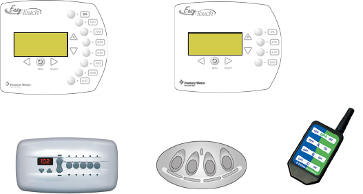
iS4 Spa-Side QuickTouch® wireless
EasyTouch 4
EasyTouch 8
iS10 Spa-Side
1
EasyTouch Wireless Control Panel Installation and User’s Guide
Section 1
EasyTouch® Wireless Control Panel Overview
Introduction
The EasyTouch wireless control panel gives you the freedom to control your pool and spa daily operations
from around your pool and spa area. The wireless device can operate up to 300 feet from the EasyTouch
transceiver module which is typically located near the EasyTouch load center. There is enough battery power
to operate the whole summer season without changing batteries, Using the power saving menu options you can
also reduce power consumption and extend battery life. The EasyTouch wireless control panel is water
resistent, however, it’s not intended to be submersible.
Operating EasyTouch
The EasyTouch system is designed to automatically control your pool and spa equipment, lights and other
optional equipment. However, you can also manually control all EasyTouch system operations from the outdoor
control panel. Using the “Mode” button, the system can be switched from “Auto” mode (normal operating
mode) to “Service” mode for manual operation and service purposes. Using the outdoor control panel buttons
you can manually override any automatic settings. If required, the EasyTouch wireless control panel can be
password protected. To access a password protected control panel, simply enter the correct four digit assigned
password (see page 51).
EasyTouch Systems
There are two EasyTouch system configurations available; EasyTouch 8 (auxiliary circuits) and EasyTouch 4
(auxiliary circuits). The EasyTouch system is factory configured to operate with a “shared” equipment system
or with a “single body” system. For EasyTouch 4 and EasyTouch 8 menus, see page 13.
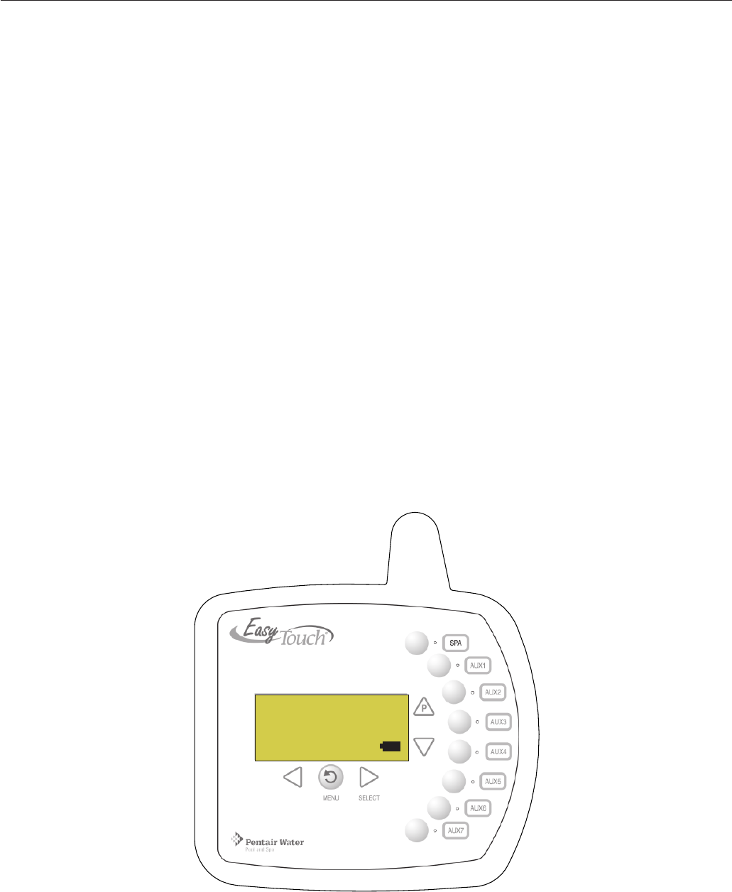
AUTO HEATER
SPA 85°F/ 95°F
AIR 70°F FRZ
MON 09:30 AM
POWER ON
EasyTouch Wireless Control Panel (Eight auxiliary circuits)
2
EasyTouch Wireless Control Panel Installation and User’s Guide
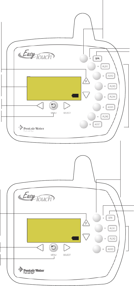
EasyTouch Wireless Control Panel Overview
The EasyTouch Wireless Control Panel makes it easy for you to control your pool and spa daily operations
from inside your home. Using the “Pool” and “Spa” buttons allows one touch control to heat and filter your spa
and pool. EasyTouch automatic system operations can be performed either at the Wireless Control Panel or
from the outdoor control panel. The Wireless Control Panel connects to the motherboard in the EasyTouch
load center.
For details about the
control panel LCD
status messages, see
page 5.
AUTO HEATER
SPA 100°F / 95°F
AIR 70°F FRZ
MON 09:30 AM
AUTO HEATER
SPA 100°F / 95°F
AIR 70°F FRZ
MON 09:30 AM
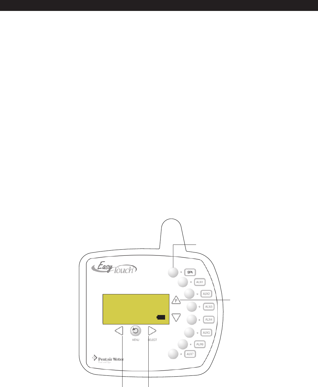
Circuit LED.
Circuit name
label.
Spa (Hi-Temp) Button: Switches the
filter pump on, rotates valve actuator
(to isolate spa water from pool
water), and switches the heater on.
Hi-Temp (EasyTouch single body
system) sets the high temperature
settings for the spa, see page 39.
Circuit LED.
Circuit name label.
Spa (Hi-Temp) Button:
Switches the filter pump on,
rotates valve actuator (to
isolate spa water from pool
water), and switches the
heater on. Hi-Temp
(EasyTouch single body
system), Can be assigned for
high temperature settings,
see page 39.
Pool (Lo-Temp) Button:
Switches the filter pump on,
rotates valve actuator (to isolate
pool water from spa water), and
switches heater on.
Lo-Temp (EasyTouch single body
system) sets the low tempera-
ture settings for the pool, see
page 39.
Pool (Lo-Temp) Button:
Switches the filter pump on,
rotates valve actuator (to
isolate pool water from spa
water), and switches heater
on.
Lo-Temp (EasyTouch single
body system), can be as-
signed for low temperature
setting, see page 39.
Wireless Control Panel (EasyTouch 8) - (P/N 520547)
Wireless Control Panel (EasyTouch 4) - (P/N 520546)
Seven user defined
auxiliary circuits.
Buttons switch the
assigned circuit
function on/off (12
hour time-out). If solar
equipment is not being
used, use the AUX
EXTRA (Down arrow
button) for an
additional circuit (see
page 4 for details).
Three auxiliary buttons
switch the assigned
circuit function on/off
(12 hour time-out). If
solar equipment is not
being used, use the
AUX EXTRA (Down
arrow button) for an
additional circuit (see
page 4)
Power ON, Menu/Back button,
see page 4.
Set Temperature buttons,
see page 4.
Set Temperature buttons,
see page 4.
Power ON, Menu/Back
button,
see page 4.
3
EasyTouch Wireless Control Panel Installation and User’s Guide
EasyTouch Wireless Control Panel Buttons
Spa button/LED: For spa operations. Press the Spa button to activate the filter pump, rotate the
pool/spa valve actuators and circulate the spa water (LED on). Press the button again to switch the
filter pump off (LED off). While the valves are rotating into position the filter pump will switch off.
For service or testing purposes, if the heater is enabled in the Heat menu, pressing this button will
also activate the heater. For normal spa operations the heater is automatically switched on with the
filter pump (see Man Heat page 38) regardless of the Heat menu setting. When this button is
pressed the circuit is activated, the LED is on and “SPA” is displayed on the screen with the current
and set point water temperatures. Once the filter pump is switched on it will run for 12 hours unless
it is switched off. When this button is pressed, the LEDs on the outdoor control panel Filter Pump
(F) button, Valves (V) button, and Heater button (if enabled in the Heat menu) will be on. If this
display line is blank, it indicates no spa or pool function is currently active.
Pool Button: For pool operations. Press the Pool (P) button to activate the filter pump, rotate the
pool/spa valve actuators and circulate the pool water and switch on the heater (if enabled in the
Heat menu). Press the button again to switch the filter pump off. While the valves are rotating into
position the filter pump will switch off. When this button is pressed the circuit is activated and
“POOL” is displayed on the screen with actual and set point water temperatures. When the filter
pump is switched on it will run for 12 hours unless it is switched off. When this button is pressed, the
LEDs on the outdoor control panel Filter Pump (F) button, Valves (V) button, and Heater button (if
enabled in the Heat menu) will be on. If this display line is blank, it indicates no pool or spa function
is currently active.
➀
➁
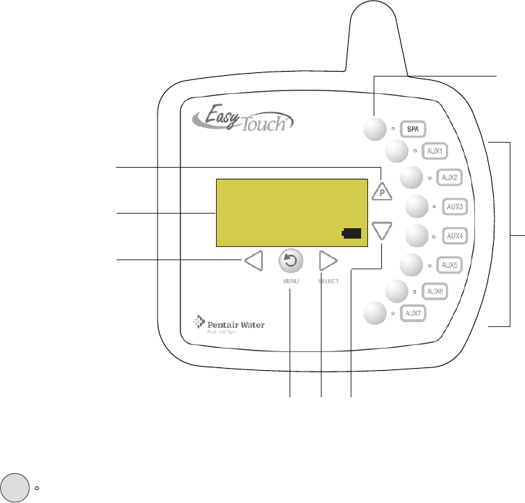
EasyTouch Wireless Control Panel Buttons
You can fully automate your pool, spa, and lighting operations from the EasyTouch Wireless Control Panel or
from the EasyTouch outdoor control panel located at the pool equipment pad. The EasyTouch menu features
let you create customized schedules for your pool and spa equipment, heat temperatures, and chlorination
P
EasyTouch Wireless Control Panel
➁
➅➆
➇
➀
AUTO HEATER
SPA 100°F / 95°F
AIR 70°F FRZ
MON 09:30 AM
➃
➂
➄

4
EasyTouch Wireless Control Panel Installation and User’s Guide
Controls and buttons (Continued)
Pool button (Continued)
•Single-Speed Filter Pump: If the pump is currently off, press the Pool button to switch the pump
on. Press the Pool button again to switch the pump off. However, if the heater is operating, and a
delay is enabled for valves, this allows the heater to cool down (heater cool-down), then when you
press the Pool button to switch off the pump, only the heater will turn off, then the filter pump will
automatically switch off after 10 minutes to allow the heater to cool down. Pentair Water Pool and
Spa® heaters do not require a cool down time. To override the “heater cool-down,” press the Pool
button again to switch off the pump.
•Two-Speed Filter Pump: Press the Pool button to switch the two-speed pump on in high speed.
Press the Pool button again to run the pump in low speed. In order to use the “2-Speed Pump” menu
assignments (see page 44), the 2-Speed relay option must be installed in the EasyTouch Load
Center.
Notes about Freeze Protection: This function protects the pool, plumbing, and equipment against
freeze damage. If the outside air temperature sensor falls below 36° F (2° C), “Freeze Protection” is
activated and the Filter Pump relay is switched on to circulate the pool water. To enable freeze
protection for a circuit, see “Settings Menu: Circuit Functions, ” on page 41.
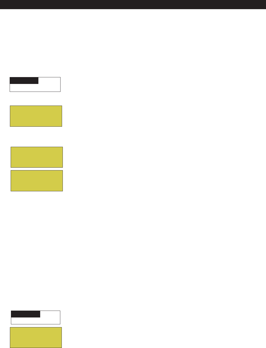
Liquid Crystal Display (LCD): The main system display consists of a 16 x 4 alphanumeric character
LCD with EL backlighting for easy viewing of the menu items, and status messages. Press the
Menu button twice to refresh the display. For main screen status information, see page 5.
Left button: When in pool or spa mode, press the Left button to lower the set point water
temperature. Press the Spa or Pool (Up arrow P) button (page 3) to display the current water
temperature. While in the main menu, press the Left button to scroll through sub-menu selections,
setting and values. While editing settings, press and hold the Left button to fast reverse through
settings and values.
Power ON, Menu/Back button: Use this button to power on the EasyTouch wireless control panel if
there has been no button activity for 60 seconds (see page 48). The Menu/Back button to access,
save and exit the EasyTouch system menu settings. Use this button to exit from main menu or sub-
menu items. Pressing the Menu/Back button while in a menu item will return to the main status
screen. If no menu activity is detected after five minutes, the main screen is displayed. All menu
settings are permanently saved and retained in the control panel even after power is removed from
the control panel. Control panel buttons are disabled while in “menu” mode.
Right button: When in pool or spa mode, press the Right button to raise the set point water
temperature. Press the Spa or Pool (Up arrow P) button (page 3) to display the current water
temperature. Press the Right button to select a sub-menu item for editing. After pressing the Menu
button to access the main menu items, press the Right button to select the menu item and access the
sub-menu items for adjustment. While editing a settings, press and hold the Right button to fast
forward through settings and values.
Up/Down buttons: Press the Up and Down buttons to scroll through the main menu items and to
adjust or change settings. Use these buttons after pressing the Menu button to access the main menu
items. While editing settings, press and hold the Up or Down button to fast forward or fast reverse
through settings and values.
Down arrow button (Aux Extra): This button switches the assigned circuit on or off. This “extra”
auxiliary circuit shares the solar circuit and is only available if the solar output plug (J17) on the
motherboard is not being used for solar equipment. Refer to the EasyTouch User’s Guide
(P/N 520584) for more information.
➄
➅
➃
➆
MENU
SELECT
➂
5
EasyTouch Wireless Control Panel Installation and User’s Guide
➇
Controls and buttons (Continued)
AUX buttons/LEDs: The auxiliary output circuit buttons operate the pool and spa system valve
actuators, lights and other equipment. The auxiliary (AUX) relay circuits are assigned in the “Circuit
Functions” menu, see page 41 for details. There are three auxiliary circuits (AUX 1- 3) on the
EasyTouch 4 Wireless Control Panel and seven auxiliary circuits (AUX 1- 7) on the EasyTouch 8
Wireless Control Panel. The Down arrow button can also be used as an “extra” auxiliary circuit if
solar equipment is not being used. Refer to “Down arrow button” on page 4 for more information.
Labels can be affixed next to each auxiliary button to identify the circuit function. When an auxiliary
circuit is activated or the button is pressed, the LED is on. Pressing an auxiliary circuit button will
activate the corresponding circuit in either “Auto” or “Service” mode. When a circuit relay is
switched on manually, it remains on until either you switch it off manually, or the next time the relay
is scheduled to be switched off. For example, if the filter pump is scheduled to automatically run
from 9:00 AM to 5:00 PM daily then the filter pump is switched on manually at 9:00 PM, it will run
continuously until the next day at 5:00 PM then switch off. The schedule will then continue from then
on. AUX buttons are disabled while in the main menu.
EasyTouch Wireless Control Panel Display
The Wireless Control Panel screen displays when the system is in automatic mode (AUTO) or in service
mode (SERVICE). Service mode is enabled from EasyTouch outdoor control panel at the pool equipment pad.
The following describes the main status screen. HEATER: Heater is switched on. Displays when the Pool (P) or
Spa button is pressed. For pool operations the heat source must
be enabled in the Heat menu (see page 23). Displays “Solar” or
“Solar Prf” if solar is enabled. The heater is active when the set
temperature is higher than the water temperature. The heater will
switch off when the water temperature rises above the set
temperature.
SPA (Hi-T) or POOL (LO-T) : Displays when the Spa/HI-T or
Pool/LO-T button is pressed to rotate valve actuators and
activate the filter pump and heater. This line on the screen is
blank when no spa or pool function is active. Note: Depending on
the EasyTouch system, the screen displays SPA (shared
equipment), HI-T (single body of water system), POOL (shared
equipment), LO-T (single body of water system).
95° F / 100° F: Displays the actual spa or pool water temperature
(95° F) and the set point temperature (100° F) as set in the
Heater menu. Degree units are displayed in either Fahrenheit or
Celsius.
AIR: Displays the actual outside air temperature (70° F) as read
by the air sensor located near the EasyTouch Load Center.
Degree units are displayed in either Fahrenheit or Celsius (see
page 46).
FRZ: Displays when freeze protection is active. To protect pool
system equipment, freeze protection must be enabled for the
filter pump circuit. If the outside air temperature sensor detects
the temperature is getting close to freezing point (below 36° F
(2° C)), the freeze protection feature switches on the filter pump
circuit to circulate water through the system. For more informa-
tion, see page 41.
DEL: Displays when “Delay Cancel” is active. For more informa-
tion, see page 24.
Date and Time: Displays the EasyTouch system day and time
as specified in the “Clock” menu setting (see page 29).
Battery icon: Displays the available battery power usage
for the device. See page 6 for details.
AUTO HEATER
SPA 95°F / 100°F
AIR 36°F FRZ
MON 09:30 AM
Lower set
temperature
Raise set
temperature
AUTO (Automatic): The system is in
normal operating mode.
Scheduled programs will run automatically.
SERVICE or TIMEOUT mode are displayed
when the system is being serviced. These
modes are activated from the EasyTouch
Outdoor Control Panel.

6
EasyTouch Wireless Control Panel Installation and User’s Guide
Battery Overview
The average battery life for the EasyTouch wireless control panel can last the summer season with normal
use. Battery life varies depending on the type of batteries used and the amount of usage. The following battery
types are compatible with the EasyTouch wireless control panel:
•AA-size alkaline battery (four provided in the kit)
•AA-size Ni-MH rechargeable battery (four purchased separately)
Safety Precautions when using batteries
Read the following important information before installing batteries into the EasyTouch wireless control panel.
• Never use batteries with split or peeling outer casings
• Never use combinations of different types of batteries or new and used batteries together
• Do not use manganese or Ni-Cd batteries
• Ensure that batteries poles are clean. Dirty poles can shorten battery life
• The time for which AA-size alkaline batteries can be used vary depending on the brand. Some brands
may provide less power than others. Note that the time Alkaline batteries can be used decreases in
cold conditions (0° C to 10° C (32° F to 50° F)). Therefore, it is recommended to use AA-size
Ni-MH batteries in the unit.
• When first purchased, or if left unused for a long period, the amount of time that the AA-size alkaline,
Ni-MH, or rechargeable batteries can be used, may be shortened.
Checking the battery charge
A check battery status icon displays on the main screen of the EasyTouch wireless control panel. The check
battery icon is located in the lower right corner of the main screen.
Check battery icons
Ample battery charge.
Sufficient charge left in the batteries to operate the unit. The unit’s estimated battery life varies
greatly depending on use and backlight display time (see page 7).
Batteries are depleted. Before the batteries are completely depleted this icon will start flashing,
indicating that the LCD will shortly go blank and the EasyTouch wireless will stop working.
Replace or recharge the batteries. Depending on the type of batteries installed, this icon may
display more quickly.
AUTO HEATER
SPA 95°F / 100°F
AIR 70°F
MON 09:30 AM
7
EasyTouch Wireless Control Panel Installation and User’s Guide
Power Save Options
Use the power save function to reduce power consumption and extend battery life. The power save options
are:
•Idle Time: If there is no control panel activity, the idle time can be set to 60 seconds (default), 30
seconds, or five minutes before it shuts down. The default time is 60 seconds. For information about
accessing the idle time options menu, see page 48.
Note: If the unit is not used for 60 seconds the power save function switches off the unit. To switch the
unit on, press the POWER ON button (see page 4).
Backlight Options
Use the backlight on time power save options to reduce power consumption and extend battery life. To access
the Backlight options menu, see page 48. The backlight options are:
•On Time: Backlight is on for 60 seconds, 30 seconds, five minutes, or off. The default setting is 30
seconds.
•Brightness: Backlight brightness can be set to low, medium or high. The default setting is medium.
Installing Batteries
The EasyTouch wireless control panel is shipped with four AA-size alkaline batteries. Before using the unit
install the batteries.
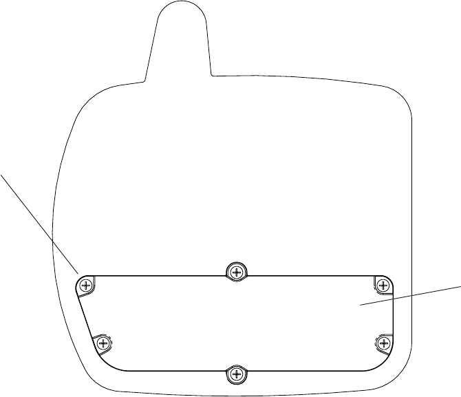
To install batteries:
1. Place the EasyTouch control panel face down on a flat clean surface. Remove the six screws
securing the battery cover. Set the cover aside.
Screw (6x)
Easy Touch Control Panel (rear view)
Battery cover
8
EasyTouch Wireless Control Panel Installation and User’s Guide
Installing batteries (Continued)
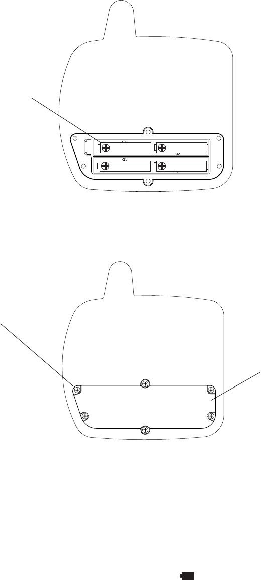
2. Load the four batteries into the battery compartment. Orient the positive polarity end of each battery
as shown below.
3. Install the battery cover and secure with the six screws. Make sure that the battery cover is secure
and that all the screws are hand tightened. CAUTION - DO NOT OVER TIGHTEN THE SCREWS.
OVER TIGHTENING THE SCREWS CAN DAMAGE THE UNIT.
4. Power up the unit: To switch the unit on, press the Power On button located on the front of the
unit.
5. Display messages after replacing batteries: After replacing depleted batteries a check battery
message is displayed on the screen. Press the MENU button to continue.
6. The screen will then display a second message to check the battery cover. After checking that the
battery cover is secure and that all screws are tightened, press the MENU button.
The battery icon should display the fully charged icon ( ). The unit is ready for use.
(+) positive polarity
Secure battery
cover with the six
screws
Easy Touch Control Panel
(rear view)
Battery cover
9
EasyTouch Wireless Control Panel Installation and User’s Guide
Quick Start - Pool and Spa Operations (Shared Equipment)
The following describes how to adjust heat temperature for the spa and pool water, schedule a daily run time
for the pool/spa filter pump and control lights for shared equipment.
Heating the Spa
Heating the spa water on demand is easy, just press the SPA button to switch the heater on and display the
current temperature settings on the EasyTouch Wireless Control Panel. “Heater” will be displayed on the screen
when the heater is active. The heater is active when the set temperature is higher than the water temperature.
The heater will switch off when the water temperature rises above the set temperature. For more information
about the spa manual heating “MAN HEAT” feature, see page 38. Pressing the Spa button will switch the filter
pump on and rotate the spa valve actuator to isolate and circulate the spa water from the pool water.
Heating the Pool
Heating the pool water is normally part of the daily scheduled program (see page 25). However, if you need to
adjust the pool water temperature, press the Pool (P) button to display the current temperature settings on the
EasyTouch Wireless Control Panel. “Heater” will be displayed on the screen when the heater is active and a
heat source has been selected in the Heat menu. The heater is active when the set temperature, as specified in
the Heat menu, is higher than the water temperature. For more information about selecting a heat source and
setting the pool water temperature setting, see page 23. Pressing the Pool button will switch the filter pump on
and rotate the pool valve actuator to isolate and circulate the pool water from the spa water.
Adjusting the water temperature setting
To adjust the set temperature setting for the pool or spa water, either use the Left arrow button to lower the
temperature setting or the Right arrow button to higher the temperature setting.
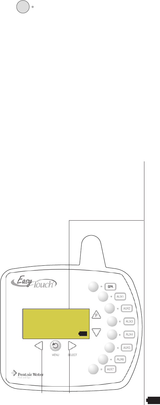
POOL button
EasyTouch Wireless Control Panel
AUTO HEATER
SPA 85°F / 100°F
AIR 70°F
MON 09:30 AM
RIGHT arrow button
Raise water set point temperature
LEFT arrow button
Lower water set point temperature
SPA button
10
EasyTouch Wireless Control Panel Installation and User’s Guide
Quick Start - (Pool and Spa Operations (Shared Equipment) Continued
Schedule start and stop times for equipment
From the Schedules menu you can set the a start and stop time to automatically run pool and spa equipment
and control underwater and backyard lights. For example, the filter pump relay circuit can be scheduled to run
the daily pool and spa filtration at a specific time and day(s) of the week. Up to 12 total program schedules
may be created for all relay circuits combined. The pool and spa circuits can also be scheduled to switch on
the heater to heat the pool or spa water up to the set point temperature as set in the “Heat” menu (see page
23). If the pool has a separate jet pump or blower controlled by AUX 1 and/or AUX 2 , these need to be
scheduled separately.
Schedules
To create a schedule to heat the spa:
Right button: Select the Spa circuit. The standard generic circuit names are: Spa,
Pool, Aux 1-7, Feature 1-8 (EasyTouch 8), Aux 1-3, Feature 1-4 (EasyTouch 4), and
Aux Extra “Aux Extra” is only available if the Solar output (J17) plug on the
EasyTouch motherboard is not being used for solar equipment.
Right button: Select Mode if there are existing programs. Skip this step to create a
new program.
Up/Down button: Select New to create a new program.
Right button: To create a new program and enter the Mode settings.
Up/Down button: 1/1 indicates that this circuit has one program. If there are existing
programs assigned to this circuit, use these buttons to view and select the existing
program settings.
Right button: To select the Schedule settings. Right button: Move to start and stop
time settings.
Up/Down and Right buttons: Set start and stop hour (A/P), minutes.
The A (AM) and P (PM) time is set when setting the start and stop hour (6:00 PM to
8:00 PM).
Right button: Move to days of the week to run the program.
Right and Up/Down buttons: By default the program is set to run all the days of
the week. If you wish to edit which days to run the program, select the day of the
week, then press the Up/Down button to remove the bar from the top of the letter. A
bar on top of the letter indicates the day selected to run the program. In this example
Sunday and Tuesday are scheduled.
Press the Menu button to save the settings and to return to the Schedules menu
options. Press the button again to return to the main menu options or press again to
return to the Main screen.
SPA 1/1
Mode: Schedule
06:00P - 08:00P
smtwtfs
_ _
SPA 0/0
Mode: New
SPA 0
POOL 0
AUX 1 0
AUX 2 0
Controlling Lights
From the Lights screen you can manually switch all lights on or off, configure and synchronize colored lights.
For more information about setting up IntelliBrite colored show modes, fixed colored lights, SAm and SAL
Color Swim and Color Set modes, refer to the Lights Menu on page 16.
To manually switch on or off all lights:
Up/Down button: Select: All Off or All On.
Press the Menu button save the settings and to return to the main menu items or
press the button again to return to the Main screen.
Modes
Colors
All On
All Off
Getting There
MENU LIGHTS LIGHTS
▲
▲
Getting There
MENU ▼ SCHEDULES SPA
▲

11
EasyTouch Wireless Control Panel Installation and User’s Guide
Setting up the EasyTouch wireless control panel
In order for the EasyTouch wireless control panel to communicate with the EasyTouch system outdoor control
panel, the first time the wireless device is powered up it must first be assigned a unique communication
address. For this process you need to access the menu for each control panel. For conveniens it’s easier to
setup the wireless device at the outdoor control panel.
Note: Before you start verify that the transceiver antenna is connected to the EasyTouch load center.
For installation instructions, refer to “EasyTouch Transceiver Installation,” on page 65.
From the EasyTouch load center outdoor control panel
1. Switch power on to the EasyTouch load center.
2. Press Menu button, and select Settings > Address and press the Right arrow button.
The EasyTouch outdoor control panel will display "Scanning..." for about five seconds while it
searches for the EasyTouch wireless device within range of the transceiver antenna. After the
scanning process has finished, "Sending Address" is displayed. The system is now waiting to lock on
to the EasyTouch wireless control panel. Proceed to step 3.
From the EasyTouch wireless control panel
3. Press the Power On button located on the front of the wireless device.
Note: After replacing depleted batteries a check battery message is displayed on the screen. Press
the MENU button twice to continue.
4. Press Menu button, and select Settings > Address and press the Right arrow button.
5. Select “Address” and press the Right arrow button to lock on to the unique address that is being
transmitted from the outdoor control panel.
Note: If you choose "Abort," the device can continue to operate using the factory default
address. If the outdoor control panel has been previously addressed, the wireless may not
operate the system. Each time the device is switched on the “NO ADDRESS” will be displayed.
This mode is not recommended for permanent use.
6. After selecting “Address” the wireless device unit will lock on to a unique address and display
"Found ADDRESSED." Press the Menu button to save and exit this mode. The device is ready for
operation. If “Unit Mismatch” displays
7. On the outdoor control panel: Press the outdoor control panel Menu button three times to exit the
"Sending Address" mode and return to the main screen. The system will continue to transmit an
address until the Menu is button is pressed to stop the process.
Note: To readdress the EasyTouch wireless device, repeat steps 2 through 7 on the wireless
device to restart the address process.
Setting up the EasyTouch wireless control panel for the first time
Address Lock
Found
ADDRESSED
<MENU>
Address Wireless
Sending Address..
<MENU>
Address Wireless
Scanning ...
NO ADDRESS
Address
Abort
Unit Mismatch
Download from
Outdoor
Note: “Unit Mismatch” displays if the
outdoor control panel has an existing
system image. See page 12 for details.
12
EasyTouch Wireless Control Panel Installation and User’s Guide
Synchronizing control panels
If the EasyTouch outdoor has been previously setup with specific pool and spa information and you install the
EasyTouch wireless control panel with factory default information, the outdoor control panel will automatically
download the existing system information to the wireless control panel. If the wireless control panel has a
different firmware revision level than the outdoor control panel or it contains previous setup information, you
can choose which system image to upload or download. Synchronizing the control panels is initiated from the
wireless control panel. The following describes how to synchronize the wireless control panel with the outdoor
control panel.
Download from outdoor to wireless control panel
•Press the Menu button to download the system image from the EasyTouch
outdoor control panel to the wireless control panel.
Upload to outdoor from wireless control panel
1. Press the Up/Down button to access the “Upload” screen.
2. Press the Menu button to upload the system image from the wireless control
panel to the EasyTouch outdoor control panel.
Note: To erase existing control panel system information, use the “Erase EEPROM” feature.
Refer to “Erase EEPROM” on page 51 for more information.
EasyTouch Menus
Unit Mismatch
Upload to
Outdoor
Unit Mismatch
Download from
Outdoor
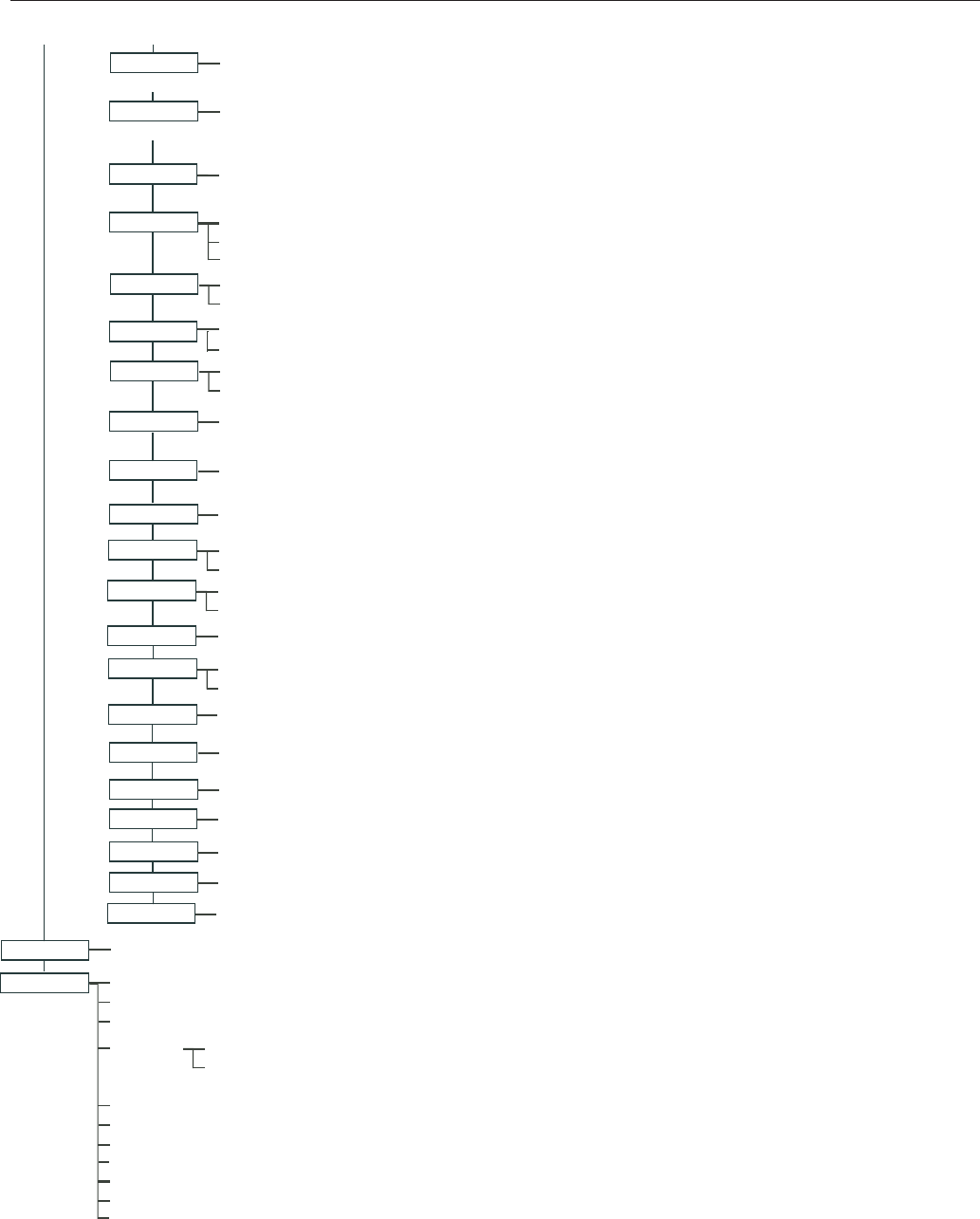
MAIN SCREEN
LIGHTS
HEAT POOL TEMP/SRC TEMP (40˚ F - 106˚ F) OR (4˚ C - 41˚ C)
HEAT (OFF/HEATER/SOLAR/SOLAR PRF) - SOLAR/SOLAR PRF MUST BE ENABLED IN "SOLAR" MENU TO DISPLAY.
SPA TEMP/SRC TEMP (40˚ F - 106˚ F) OR (4˚ C - 41˚ C)
HEAT (OFF/HEATER/SOLAR/SOLAR PRF) - "SOLAR/SOLAR PRF" MUST BE ENABLED IN "SOLAR" MENU TO DISPLAY.
DELAY CANCEL
MODE: SCHEDULE
08:00A -- 05:00P (12:00 AM - 11:59 PM -12 HOURS)
S M T W T F S (DAYS OF THE WEEK)
SCHEDULES
SPA 0
AUX 2 0
AUX 4 0
AUX 3 0
MODE: EGG TIMER
TIME: 12:00 (00:00 - 23:59) / DON'T STOP
SETTINGS
INTELLICHLOR INTELLICHLOR 1/2 - ENABLE (YES/NO), POOL MODE: 0 - 100 % (50% default) SPA MODE: 0% (2% default)
INTELLICHLOR 2/2 - SUPER CHLR (ON/OFF), RUN HOURS (0 -72)
(OPTIONAL)
CIRCUIT NAMES CIRCUIT NAMES (1/18) - [SPA, POOL, AUX 1-7 (ET8), AUX 1-3 (ET4), FEATURE 1-8, AUX EXTRA
CLOCK DATE & TIME 1/2 - (MONTH/DAY/YEAR) - (DAY/HOUR/MINUTES/AM/PM)
DATE & TIMER 2/2 - DAYLIGHT SAVING: (AUTO/MANUAL)
CLOCK ADJUST 00:00 (0 TO 300) - (-300 TO -5) IN 5 SCEOND INCREMENTS
(DELAYED CANCELLED) PRESS RIGHT BUTTON TO ACTIVATE
POOL 0
AUX 1 0
AUX 5 0
AUX 6 0
AUX 7 0
EASYTOUCH 4
EASYTOUCH 8
MODE: ONCE ONLY
08:00A (12:00 AM - 11:59 PM -12 HOURS)
S M T W T F S (SELECT DAY OF THE WEEK TO RUN PROGRAM)
MODE: NEW / DELETE / NONE
HI-TEMP (SPA) / LO-TEMP (POOL) FOR SINGLE BODY SYSTEM (SEE SETTINGS MENU: CIRCUIT NAMES)
INTELLIFLO
(OPTIONAL)
FEATURE 1-8 0
AUX EXTRA: AUXILIARY OUTPUT (USE DOWN ARROW BUTTON TO SWITCH ON/OFF). ONLY AVAILABLE IF
SOLAR PLUG (J17) IF NOT BEING USED FOR SOLAR EQUIPMENT.
MODES [6 LIGHT SHOWS, HOLD, RECALL, COLOR SWIM, COLOR SET]
COLORS [5 FIXED COLORS, HOLD, RECALL, COLOR SWIM, COLOR SET]
ALL ON (SWITCH ALL LIGHTS ON)
ALL OFF (SWITCH ALL LIGHTS OFF)
SYNC (SYNCHRONIZE COLORED LIGHTS)
MAGICSTREAM [TOGGLE THUMPER, HOLD, RESET, CHANGE MODE]
CONFIG (SETUP EIGHT LIGHT POSITIONS)
FEATURE CIR
FEATURE 1-8 [OFF]
AUX EXTRA 0
FEATURE 1 - 8
MANUALLY TURN A FEATURE CIRCUIT ON/OFF.
USE FEATURE CIRCUITS TO CONTROL PUMP SPEEDS AND VALVES.
PUMP #1 - PUMP TYPE [VF, VS, VSF, NONE] - VF: FILTR. CIRCUIT, FLOW (GPM), FILTERING, PRIMING, BACKWASH, VAC
PUMP #2 - PUMP TYPE [VF, VS, VSF, NONE] - VS: SPEEDS (RPM), PRIMING, STATUS - VSF: FLOW/SPEEDS (RPM/GPM),
HEAT PUMP COM SETTINGS: ENABLE, DISABLE (NO/YES) - [HEATING, COOLING] - STATUS
(OPTIONAL)
INTELLICHEM PH/OPR Values (pH VAL, SET - OPR VAL, SET) - Status (pH/OPR level) - Saturation Index (CH,TDS,TA,SI)
(OPTIONAL)
13
EasyTouch Wireless Control Panel Installation and User’s Guide
Section 2
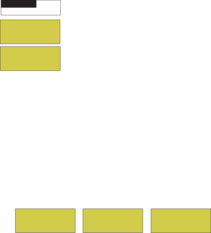
EasyTouch Menus (Continued)
CIRCUIT NAMES CIRCUIT NAMES (1/18) - [SPA, POOL, AUX 1-7 (ET8), AUX 1-3 (ET4), FEATURE 1-8, AUX EXTRA
CIRCUIT FUNC. CIRCUIT: (SPA [MASTER SPA], POOL [MASTER POOL], AUX 1-7 (AUX 1-3), FEATURE 1-8, AUX EXTRA - FUNCTIONS: GENERIC, MASTER SPA, MASTER POOL,
FREEZE: NO/YES
CUSTOM NAMES CSTM NAME 1/10 (ASSIGN UP TO 10 CUSTOM NAMES)
[USERNAME-01...10] (UP TO 11 ALPHANUMERIC CHARACTERS)
2-SPEED PUMP
CIRCUIT (NONE, SPA, POOL, AUX 1 - 3 (ET 4) - SPA, POOL, AUX 1 - 7 (ET 8), FEATURE 1-8, AUX EXTRA, SOLAR, HEATER, POOL HEATER, SPA HEATER, FREEZE)
2-SPEED PMP 1/4 (ASSIGN UP TO 4 CIRCUITS)
SOLAR
DELAYS COOL DOWN (YES/NO) - VALVES (YES/NO)
SOLAR 1/2 - ENABLE (YES/NO) - HEAT PUMP (YES/NO) - SOLAR 2/3 - FREEZE, NIGHT COOL (YES/NO)
SOLAR 3/3 (TEMPREATURE DIFFERENCE) - START (3˚-9˚ (6˚ default)) - RUN (2˚-5˚ (3˚ default))
VALVES
F˚ / C˚
iS4
FAHRENHEIT / CELCIUS
CIRCUIT - (NONE, SPA, POOL, AUX 1 - 7 (ET 8), AUX 1 - 3 (ET 4), FEATURE 1-8, AUX EXTRA, HEAT BOOST, HEAT ENABLE, PUMP INCRS, PUMP DECRS)
ASSIGN CIRCUITS 1/4
A: [NONE, SPA, POOL, AUX 1 - 3 (ET 4) - SPA, POOL, AUX 1 - 7 (ET 8), FEATURE 1-8, AUX EXTRA, HEATER] - (USED SOLAR IF SOLAR IS ENABLED)
B: [NONE, SPA, POOL, AUX 1 - 3 (ET 4) - SPA, POOL, AUX 1 - 7 (ET 8), FEATURE 1-8, AUX EXTRA, HEATER]
MSTR CLEANER, LIGHT, SAM LIGHT, SAL LIGHT, PHOTON GENERATOR, COLOR WHEEL, SPILLWAY, FLOOR CLEANER, INTELLIBRITE, MAGICSTREAM
DIAGNOSTICS SOFTWARE REV (REVISION LEVEL FOR THE OUTDOOR AND INDOOR CONTROL PANEL)
BOOTLOADER REV (REVISION LEVEL FOR THE OUTDOOR AND INDOOR CONTROL PANEL)
SELF TEST (STATUS: TESTING (FOLLOW ON-SCREEN PROMPTS TO TEST LCD AND BUTTONS) - CODE: 0 - SEE "TROUBLESHOOTING" SECTION FOR ERROR CODES)
WATER TEMP (FAHRENHEIT/CELCIUS - STATUS DISPLAY ONLY)
SOLAR TEMP (FAHRENHEIT/CELCIUS - STATUS DISPLAY ONLY) - (DISPLAYS IF SOLAR IS ENABLED IN HEAT MENU)
AIR TEMP (FAHRENHEIT/CELCIUS - STATUS DISPLAY ONLY)
DISP OP CODES - DISPLAY? NO/YES (DISPLAYS TRANSMIT/RECEIVE PACKETS NUMBERS ON SCREEN)
SPA SIDE [OFF/ON] ENABLE/DISABLE IS4 SPA-SIDE REMOTE
CIR NAMES [ON/OFF] VIEW DEFAULT CIRCUIT NAMES BEFORE MODIFICATION.
CHLORINATOR SALT LEVEL: DISPLAYS CURRENT SALT LEVEL (XXXX) PPM
STATUS: OK - NO ERRORS (SUPER CHLORINATE, COM LINK ERROR, CHECK FLOW / PCB,
LOW SALT, VERY LOW SALT, HIGH CURRENT, CLEAN CELL!!, LOW VOLTAGE)
RESET SYSTEM (REINITIALIZE INDOOR CONTROL PANEL - USE RIGHT BUTTON)
FLASH UPDATE (USED FOR FIRMWARE UPDATES VIA PC - PRESS MENU TO ABORT)
HEAT PUMP COM SETTINGS: ENABLE, DISABLE (NO/YES) - [HEATING, COOLING] - STATUS
(OPTIONAL)
10 BUTN SPA SD
ASSIGN CIRCUITS 1/5 (NONE, SPA, POOL, AUX 1 - AUX 7 (ET 8), AUX 1 - AUX 3 (ET 4), FEATURE 1-8, AUX EXTRA, HEAT BOOST, HEAT ENABLE, PUMP INCRS, PUMP DECRS))
TOP ROW (1/5), BOTTOM ROW (1/5)
QUICK TOUCH ASSIGN QT4 1/4 (ASSIGN UP TO 4 CIRCUITS)
CIRCUIT - (NONE, SPA, POOL, AUX 1 - AUX 7 (ET 8), AUX 1 - AUX 3 (ET 4), FEATURE 1-8, AUX EXTRA, HEAT BOOST, HEAT ENABLE)
ERASE EEPROM ERASE ALL (YES /NO) - ARE YOU SURE? (YES/NO)
CALIBRATION WATER (FAHRENHEIT/CELCIUS) - AIR (FAHRENHEIT/CELCIUS) - SOLAR (FAHRENHEIT/CELCIUS) - SOLAR MUST BE ENABLED IN "HEAT" MENU TO DISPLAY
SWITCH MANUAL HEAT ON OR OFF WHEN SPA IS MANUALLY SWITCHED ON (USE RIGHT BUTTON SELECT ON/OFF)
MAN HEAT [OFF/ON]
SET PASSWORD SET PASSWORD: {XXXX} 4 DIGITS - ENABLE / DISABLE [NO/YES]
10B PUMP CTRL ASSIGN IS10 and IS4 PUMP CONTROLS [PUMP NUMBER 1/2, STEP RPM: 10-250, GPM: 1-10]
INTELLICHEM PH/OPR Values (pH VAL, SET - OPR VAL, SET) - Status (pH/OPR level) - Saturation Index (CH,TDS,TA,SI)
(OPTIONAL)
WIRELESS ADDR SET AN ADDRESS FOR EASYTOUCH WIRELESS CONTROL PANEL
BACKLIGHT ON TIME: 5 S, 15 S, 30 S, 60 S, 5 M, OFF [BRIGHTNESS: LOW, MED HI]
POWER SAVE IDLE TIME: 15 S, 30 S, 60 S, 5 ME

14
EasyTouch Wireless Control Panel Installation and User’s Guide
EasyTouch Menus
From the EasyTouch control panel menus you can schedule everyday pool/spa, heating, filtration and cleaning.
Lights and laminars can also be scheduled to switch on and off at specific times. The “Settings” and
“Schedule” menus are typically used most often for daily spa and pool operations. The “Settings” menu is used
by the pool installer to setup installed equipment which is connected to each output relay (filter pump, auxiliary
relays, heater, valves, lights, etc.). For EasyTouch equipment installation instructions, see the EasyTouch
Installation Guide (P/N 520584).
Main Screen
The EasyTouch main screen displays the current mode of operation
(AUTO/SERVICE/TIMEOUT), heat source being used, spa (or pool) actual water
temperature (95° F), current heater set point temperature (100° F) and the current
ambient air temperature (air sensor). Degree units can be displayed in either
Fahrenheit (default) or Celsius (see page 42). If the second display line is blank and
the heat source is not displayed, there is no spa or pool function currently active. The
main screen is automatically displayed if there is no control panel menu activity for
five minutes. If there is an IntelliChlor® salt chlorinator generator being used, pool and
spa sanitizer settings, and salt levels can be viewed in the Diagnostics, “Chlorinator,”
settings (see page 55).
Main Screen Description
AUTO: EasyTouch is in normal (automatic) operating mode. For information about “Service” and “Timeout”
operating modes, see page 4.
HEATER: The selected heat source as selected in the “Heat” menu (see page 23). The heat options are:
•OFF - No heating even though pump and other circuits may be operating.
•HEATER - Gas heater only.
•SOLAR ONLY - Solar heating system to be the only heat source. In order to display “Solar Pref.” on
the main screen, you must first enable solar in the “Solar” menu (see page 40).
•SOLAR PREF. - (Solar Preferred) - For when solar and gas heating are combined, and you want to
use solar heating only when it is most effective. In order to display “Solar Pref.” on the main screen,
you must first enable solar in the “Solar” menu.
SPA: “SPA” is displayed after the Valves (V) button is pressed to set in “spa” mode then the Filter (F)
button is pressed to switch the filter pump on, rotate the valve actuator (to isolate spa water from pool water),
and switch the heater on (if enabled in the “Heat” menu). Pressing the Valves (V) button alternates between
“Pool” and “Spa” mode. The temperature unit displayed on the left side is the actual water temperature (95°
F) and the set point temperature (100° F) as set in the “Heat” menu is displayed on the right side. If this
display line is blank, it indicates no spa or pool function is currently active. For Hi-Temp controls (EasyTouch
single body system), see page 39.
POOL: “POOL” is displayed after the Filter (F) button is pressed to switch the filter pump on, rotate the
valve actuator to isolate the pool water from the spa water, and switch the heater on (if enabled in the “Heat”
menu). Pressing the Valves (V) button alternates between “Pool” and “Spa” mode. The temperature unit
displayed on the left side is the actual water temperature (95° F) and the set point temperature (100° F) as set
in the “Heat” menu is displayed on the right side. If this display line is blank, it indicates no spa or pool function
is currently active. For Lo-Temp controls (EasyTouch single body system), see page 39.
AIR: Displays the actual outside ambient air temperature (70° F) as recorded by the air sensor located near
the EasyTouch load center.
DAY and TIME: The current system day and time (AM/PM). See the “Clock” menu to set the system day and
time (page 29).
AUTO HEATER
SPA 95°F / 100°F
AIR 70°F
MON 09:30 AM
AUTO
AIR 70°F
MON 11:30 AM
AUTO HEATER
POOL 85°F / 95°F
AIR 70°F
MON 10:30 AM

15
EasyTouch Wireless Control Panel Installation and User’s Guide
Feature Circuits Menu
There are eight (8) “Feature Circuits” that can be used to control IntelliFlo® pump speeds or valves actuators
for a spa spillway. Unlike an auxiliary relay circuit, a “Feature” circuit does not connect directly to a relay.
“Feature” are turned on and off from the control panel “Feature” circuit menu.
Feature Circuits
To switch a feature circuit ON or OFF:
Right button: Select the feature circuit to turn ON or OFF..
Up/Down buttons: Choose assigned feature circuit: FEATURE 1 - 8.
Right button: Switch the selected feature circuits ON or OFF.
When finished, press the Menu button twice to return to the main screen.
Getting There
Menu F. Circuits
▲
F. Circuits
Lights
Heat
Delay Cancel
FEATURE 1 [ON]
FEATURE 2 [OFF]
FEATURE 3 [OFF]
FEATURE 4 [OFF]
FEATURE 5 [ON]
FEATURE 6 [OFF]
FEATURE 7 [OFF]
FEATURE 8 [OFF]
16
EasyTouch Wireless Control Panel Installation and User’s Guide
Lights Menu
From the Lights screen you can manually switch all lights on or off, and synchronize colored lights. Up to
eight (8) lights (EasyTouch 8) or 4 lights (EasyTouch 4) can be independently controlled from the Lights
screen. Each light requires a separate auxiliary relay circuit. Up to four lights can be assigned on each
auxiliary circuit. A circuit name must be assigned to the AUX relay circuits which controls the light. Verify that
IntelliBrite, SAm and/or SAL, and/or FIBERworks have been selected in Circuit Function. If FIBERworks
lighting is being used, it also has to be set up as a Photon Generator® (PHOTON GENERATOR) for the
circuit controlling the light bulb, and COLOR WHEEL for the circuit controlling the color wheel. For more
information about setting up lights, see “Settings Menu: Circuit Function,” on page 41.
The Color Swim and Color Set Lighting Features
The Color Swim and Color Set lighting features is selected from the LIGHTS > MODES and (COLORS)
menu. At least two (2) Pentair Water Pool and Spa® IntelliBrite®, SAm®, SAL® and/or FIBERworks® lighting
systems are required to use the lighting features.
• Color Swim - Select the Color Swim feature in the MODES and COLORS menus to start lights to
transition through colors in sequence to give the appearance of colors dancing through the water. You
can adjust the delay of each light to make the colors move at different speeds using the LIGHTS >
CONFIG option. This lighting feature requires a separate relay for each light. To switch off the Color
Swim feature, select the AUX button assigned to the light circuit or select ALL OFF in the Lights
menu.
• Color Set - Select the Color Set feature in the MODES and COLORS menus to switch the light on
using specific color as selected in the COLORS menu. This feature requires a separate relay for
each light. To switch off the Color Swim feature, select the AUX button assigned to the light circuit
or select ALL OFF in the Lights menu.
• Configure - Select “Configure” to setup the positions of the lights the pool. Up to eight (8) lights can
be assigned a position. For more information see page 20.
• Sync - Select the Sync feature in the LIGHTS menu to switch on all IntelliBrite, SAm, SAL, or
FIBERworks color changing lights and synchronize their colors.
• Smart Start (SS: Yes/No) - Select Smart Start in the Schedules menu (see page 25). The Smart Start
feature automatically starts changing colors when the lights are programmed to switch on. Smart
Start is used when Color Swim and IntelliBrite show modes are being used.
Getting There
MENU LIGHTS LIGHTS
▲
▲
All On
All Off
Sync
Configure
1- [NONE ]
2- [NONE ]
3- [NONE ]
4- [NONE ]
1- [AUX 1 ]
2- [LT.GREEN ]
3- [1ST POSITION ]
4. [DELAY 5 SECS]
Modes
Colors
All On
All Off
Hold
Recall
Color Swim
Color Set

17
EasyTouch Wireless Control Panel Installation and User’s Guide
Setting up Lights
The following section describes how to assign a light circuit name and function to control Pentair Water Pool and
Spa IntelliBrite, SAm and/or SAL, and/or FIBERworks lights.
Assign the Light Circuit Name and Function
The first step in setting up a light circuit is to assign a name to the relay circuit (example; AUX 3, as “Pool Light”),
then assign the name “Pool Light” circuit in the Circuit Func. menu as a “light” circuit (IntelliBrite, SAM, SAL..).
The light circuit functions are: Light, SAM, SAL, Photon Generator, Color Wheel, Spillway, MagicStream and
IntelliBrite (see page 42). After assigning the circuit name and function, the light circuit name “Pool Light” can be
setup in the CONFIG menu for light position, color etc.
To assign a circuit function:
Up/Down buttons: Select the circuit number 1/18. Press the Up button two times
to select AUX 1 to choose this circuit for a light circuit On/Off button. The generic
circuits names are: Spa, Pool, Aux 1-7 (EasyTouch 8), Aux 1-3 (EasyTouch 4),
FEATURE 1-8 (Ft. 1-8), AuxX (Aux Extra). The circuit number (1/18) corresponds
to its assigned circuit name.
Right button: Select the EasyTouch preset circuit names and user defined custom
circuit names.
Up/Down buttons: Scroll through the list of preset names (see page 36 for a
complete list of circuit names). Select a name that describes where the light is located
or that suits the function, such as “Pool Light.” AUX 1 has now been assigned the
circuit name “Pool Light.” If you cannot find a name to match your circuit, you can
create your own custom name (see page 36). Repeat this step for all the circuit
buttons that you wish to assign names to. “Aux Extra” is only available if the Solar
output (J17) plug on the EasyTouch motherboard is not being used for solar
equipment. The Down arrow button is used to turn the “extra” circuit on and off.
Press the Menu button to return to the Settings menu. Press the Down button to and
select “Circuit Func.” Press the Right button to access the Circuit Func. menu.
Up/Down buttons: Select the already assigned circuit name “Pool Light.”
Right button: View “Circuit Functions” to assign to light circuit “Pool Light.”
Up/Down buttons: Select the type of light circuit function to use. The circuit
function names are: LIGHT, SAM LIGHT, SAL LIGHT, PHOTON GEN, COLOR
WHEEL, VALVE, SPILLWAY, FLOOR CLEANER, INITELLIBRITE,
MAGICSTREAM, GENERIC, and MSTR CLEANER. For a complete list of preset
circuit functions, see “Preset Circuit Functions” on page 42.
Note: To use the “Color Swim” or “Color Set” feature, select IntelliBrite, SAM, SAL,
Photon Generator or Color Wheel. Select “MagicStream” for MagicStream laminars.
Press the Menu button three times to return to the main screen.
Circuit Names
Circuit #: 1/18
Circuit : AUX 1
[POOL LIGHT ]
Circuit / Func. :
[POOL LIGHT ]
[INTELLIBRITE ]
Freeze: No
IntelliFlo
IntelliChlor
Circuit Names
Circuit Func.
MENU ▼ SETTINGS ▼ CIRCUIT FUNC.
▲
Getting There
MENU ▼ SETTINGS ▼ CIRCUIT NAMES
▲
Getting There

18
EasyTouch Wireless Control Panel Installation and User’s Guide
Setting up lights
From the Lights screen you can manually switch all lights on or off, synchronize colored lights, and activate
color light shows. Up to eight (EasyTouch 8) or four (EasyTouch 4) light circuits can be configured from the
“Config” light menu. Each light must have its own relay and separate circuit.
Setting up IntelliBrite Light Circuits
Before configuring the lights, be sure the auxiliary (AUX) circuits that control the IntelliBrite lights have been
assigned as an “IntelliBrite” light. For more information about “Circuit Functions” (page 37) and “Circuit
Names,” (page 40).
Lights Menu
To access the Lights menu screen, press Menu > Lights. The Lights menu settings are: MODES, COLORS,
ALL ON, ALL OFF, SYNC, MAGICSTREAM, CONFIG:
Modes (IntelliBrite Color light shows, Color Swim, Color Set)
To access the Modes menu, press Menu > Lights > Modes. There are six pre-programmed color light
shows to choose from. From the “Modes” screen you can select various preset show color lighting effects,
such as “American mode” and “Sunset mode”, “Color Swim” or “Color Set.” Using the “Hold” and “Recall”
feature (see page 19) you can also capture and save a unique color light show effect to recall at a later time.
The IntelliBrite color “Mode” settings light shows are:
•Party: Rapid color changing building the energy and excitement
•Romance: Slow color transitions creating a mesmerizing and calming effect
•Caribbean: Transitions between a variety of blues and greens
•American: Patriotic red, white and blue transition
•Sunset: Dramatic transitions of orange, red and magenta tones
•Royalty: Richer, deeper, color tones
IntelliBrite Light: If the IntelliBrite light was not previously on, after selecting a color show mode, no
illumination will occur for up to ten (10) seconds (depending on the selection), then a white light will
momentarily illuminate, followed by the color show mode selection. If the light was previously on,
selecting the a color show mode button will momentarily illuminate the previously selected color before
changing to the selected color show.
Modes (Color Swim)
The Color Swim feature cycles through white, magenta, blue and green colors. Using IntelliBrite lights, Color
Swim emulates the Pentair Water Pool and Spa SAM and SAL Color Swim feature.
IntelliBrite Light Color Swim/Color Set: If the light was not previously on, after selecting Color Swim,
no illumination will occur for approximately six (6) seconds followed by the selection. If the light was
previously on, after selecting the Color Swim feature, the previously selected color will momentarily
illuminate, no illumination will occur for approximately six (6) seconds followed by the selection.
Getting There
MENU LIGHTS LIGHTS
▲
▲
19
EasyTouch Wireless Control Panel Installation and User’s Guide
Setting up lights (Continued)
Modes (Color Set)
The “Color Set” feature allows any combination of up to eight (EasyTouch 8) or four (EasyTouch 4)
IntelliBrite lights, and Pentair SAm, SAL and or Fiberworks lighting to be preset to specific colors. Fixed light
colors are selected and activated from the Colors screen.
IntelliBrite Light: If the light was not previously on, after selecting the fixed colored light, no
illumination will occur for approximately six (6) seconds followed by the selection. If the light was
previously on, after selecting the colored light, the previously selected color will momentarily illuminate,
no illumination will occur for approximately six (6) seconds followed by the selection.
Colors
Choose any one of the five fixed colors to create a spectacular underwater lighting effect. The fixed colors
are: Blue, Green, Red, White and Magenta. You can switch each fixed colored light on or off from the
Colors screen.
IntelliBrite Light: If the light was not previously on, after selecting a fixed colored light, no illumination
will occur for up to ten (10) seconds (depending on the selection), then a white light will momentarily
illuminate, followed by the color selection. If the light was previously on, selecting the a color button
will momentarily illuminate the previously selected color before changing to the selected color.
To select a fixed color press: Menu > Lights > Modes > Colors:
Up/Down buttons: Choose a color for the light.
Right button: Switch the selected colored light ON. To switch the light off, go to
the main Lights menu and select All Off, or press the AUX button assigned to the
light. The AUX button will also switch the light on.
Press the Menu button three times to return main menu.
Hold/Recall
Select Hold and Recall from the “Modes” or “Color” screen to capture and save a unique color effect and
recall it at a later time. For example, while a light show (Romance Mode) is active, select “Hold” to save the
exact colors that are being displayed, then later, to recall the exact color effect, select “Recall.”
Note: After selecting Hold or Recall, no illumination will occur for up to 10 seconds, then a white light
will momentarily illuminate, followed by the saved color.
All On / All Off (Lights Menu)
Select All On or All Off from the Lights screen to manually switch all lights on or off, including any
MagicStream laminar circuits. Press the control panel auxiliary button (AuxX) assigned to a light circuit will
also switch a light on or off.
Sync
Select Sync from the “Lights” screen to synchronize colors for all IntelliBrite, SAm, SAL, and FIBERworks
color changing lights.
WARNING - IntelliBrite Lights: During the off/on switching process, before
the selected color is displayed, no illumination will occur. This operating mode is
normal during the switching process. During this period the pool and spa will be
dark and precautions should be taken to avoid unforeseen accidents. Failure to
observe this warning may result in serious injury or death to pool and spa users.
Blue
Green
Red
White
Green
Red
White
Magenta
Magenta

20
EasyTouch Wireless Control Panel Installation and User’s Guide
Setting up lights (Continued)
Config
From the “Config” screen you can setup the IntelliBrite light position, and specify the color of each pool and
spa light. Any combination of up to eight (EasyTouch 8) or four (EasyTouch 4) IntelliBrite lights, Pentair SAM,
SAL and or Fiberworks lights can be preset for specific colors and position when using the “Color Swim” and
“Color Set” feature. Fixed light color are selected and activated from the Colors screen. Note: The “Config”
menu settings do not apply to the MagicStream laminars.
To select configure a light position and color: Menu > Lights > Config:
Up/Down buttons: Choose the light circuit (1-8) to configure. Select an available
auxiliary circuit (NONE). For more about assigning an auxiliary circuit to a light,
see “Circuit Functions (page 41) and “Circuit Names” (page 43). EasyTouch 8
supports up to eight (8) auxiliary circuits, EasyTouch 4 supports up to four (4)
auxiliary circuits.
Right button: Select the light to setup.
Up/Down buttons: Select the light circuit.
Right button: Move to the light color selection.
Up/Down buttons: Select the light color (Blue, Cyan, Green, Lt. Green,
White, Lt. Magenta, Magenta, Lavender).
Right button: Move to the light position selection.
Up/Down buttons: Select the light position. A light can be assigned to any
position from 1 through 12. To ensure that the “Color Swim” and “Color Set”
lighting feature color effects are correct, set the position of the light according to
where it’s located in the pool or spa. Position 1 will lead all the other lights in the
color changing sequence. Position 2 follows Position 1 and so on. There are 12
position to choose from. More than one light may be assigned to the same position
number so that their colors may be synchronized. For example, to make the colors
swim right to left, make your right most light Position 1. You may need to go
back to and scroll through your lights to find the right most light, and set it as
Position 1.
Right button: Move to the light delay selection. The Delay time between two or
more lights can be set from 0 to 60 seconds. Use a higher delay time for lights
spread further apart. Try five seconds for all lights and observe the effect. Use
different time settings to achieve unique lighting moods and effects.
Press the Menu button to setup other lights or press Menu button four times
to return main screen.
Setting up SAM, SAL, PG2000, Color Wheel Lights
Before using the lighting feature “Color Swim” or “Color Set” with Pentair SAM or SAL lights, make sure the
AUX relay circuits which control the lights have been assigned as “light” circuit and that the name (AUX 1,
AUX 2) has been changed to best fit the light being used. Verify that SAm and/or SAL, and/or FIBERworks
have been assigned in “Circuit Functions” as SAM or SAL light. If FIBERworks lighting is incorporated, it
also has to be set up as a “PHOTON GENERATOR” light for the circuit controlling the light bulb, and
COLOR WHEEL for the circuit controlling the color wheel it self. The circuit light “functions” are: Light,
SAM, SAL, Photon Generator, Color Wheel, and IntelliBrite, see page 42 for a more information.
1- [POOL ]
2- [SPA ]
3- [BACK YARD ]
4- [AUX 4 ]
5- [NONE ]
6- [NONE ]
7- [NONE ]
8- [NONE ]
[ AUX 4 ]
[ LAVENDER ]
[ 1ST POSITION ]
[ DELAY 5 SECS ]

21
EasyTouch Wireless Control Panel Installation and User’s Guide
Setting up MagicStream Laminars
The MagicStream® Laminar provide a clear, turbulence-free stream of water that is lit with a fiber optic cable,
or an LED light for a dazzling nighttime effect. The 12 VAC powered LED light can generate a series of
multicolored light shows, or can be set to display a continuous, single color. If desired, the built-in solenoid
“thumper” can create a random “wrinkle,” in the Laminar’s stream, causing it to display a brilliant spot of light
that moves along the stream’s arc. The light enhancer can be adjusted to maximize the light in the arc.
Up to twelve (12) MagicStream Laminar circuits can be displayed on the main Lights screen, assuming each
laminar has its own relay and separate circuit.. From the Lights screen you can activate the MagicStream
laminars (changing color modes, turn Thumper on/off, Hold and Reset). For more information, see the
MagicStream Installation Guide, P/N 520969.
Setting up MagicStream Laminar LED Lights
To setup MagicStream laminar circuits, first assign each laminar auxiliary relay circuit a circuit name (see
“Circuit Names” page 40, then assigned the laminar relay circuit name to “MAGICSTREAM” in the circuit
functions menu (Circuit Func.).
To setup the MagicStream laminar circuit names and function:
Up/Down buttons: Select the circuit number 1/18. Press the Up button two times
to select AUX 1 to choose this circuit for the MagicStream circuit On/Off button. The
generic circuits names are: Spa, Pool, Aux 1-7 (EasyTouch 8), Aux 1-3
(EasyTouch 4), FEATURE 1-8 (Ft. 1-8), AuxX (Aux Extra).
The circuit number (1/18) corresponds to its assigned circuit name.
Right button: Select the EasyTouch preset circuit names and user defined custom
circuit names.
Up/Down buttons: Scroll through the list of preset names (see page 36 for a
complete list of circuit names). Select a name that describes where the MagicStream
laminar is located or that suits the function, such as “Stream.” AUX 1 has now been
assigned the circuit name “Stream.” for the first MagicStream laminar. Repeat this
step for the next laminar circuit. If you cannot find a name to match your circuit, you
can create your own custom name (see page 40). “Aux Extra” is only available if the
Solar output (J17) plug on the EasyTouch motherboard is not being used for solar
equipment. The Down arrow button is used to turn the “extra” circuit on and off.
Press the Menu button to return to the Settings menu. Press the Down button to and
select “Circuit Func.” Press the Right button to access the Circuit Func. menu.
Up/Down buttons: Select the already assigned circuit name “Stream.”
Right button: View the “Circuit Functions” to assign to laminar circuit “Stream.”
Up/Down buttons: Select the type of circuit function to use, in this case select
“MAGICSTREAM.” The circuit function names are: LIGHT, SAM LIGHT, SAL
LIGHT, PHOTON GEN, COLOR WHEEL, VALVE, SPILLWAY, FLOOR
CLEANER, INITELLIBRITE, MAGICSTREAM, GENERIC, and MSTR
CLEANER. For a complete list of preset circuit functions, see “Preset Circuit
Functions” on page 42.
Right button/ Up Button: Turn “Freeze” protection ON.
Press the Menu button three times to return to the main screen.
Continue on next page...
Circuit Names
Circuit #: 1/18
Circuit : AUX 1
[STREAM ]
Circuit / Func. :
[STREAM ]
[MAGICSTREAM ]
Freeze: Yes
IntelliFlo
IntelliChlor
Circuit Names
Circuit Func.
MENU ▼ SETTINGS ▼ CIRCUIT FUNC.
▲
Getting There
MENU ▼ SETTINGS ▼ CIRCUIT NAMES
▲
Getting There

22
EasyTouch Wireless Control Panel Installation and User’s Guide
Using the MagicStream Laminar Features
The MagicStream laminar features are displayed in the MagicStream menu. Each time a MagicStream feature
is activated, MagicStream resumes with the same features in operation as when last switched off. The
MagicStream features are as follows:
Toggle Thumper - Pressing this button creates a "wrinkle" in the laminar stream, producing a brilliant spot
of light in the laminar arc.
Hold - Select Hold to capture the current color effect while colors are changing. The colors will stop
changing. Selecting Hold again will resume the color changing mode.
Reset - Pressing this button reverts to the Random color changing mode with the Thumper ON.
Change Mode - Pressing this button (each successive OFF/ON combination) will cycle through Sync,
Random and Party. Color changing mode - The color of the light changes automatically, according to one
the following three programs:
Sync - Colors will change at ten second intervals. In this mode, multiple laminars will synchronize
colors together. Note: To sync multiple laminars (two or more AUX circuits), be sure to define the
“MagicStream” circuits in the “Circuit Functions” menu.
Random - Colors will change at ten (10) second intervals in a random sequence. In this mode,
multiple laminars will NOT synchronize colors together.
Party - Colors will change randomly and slowly at first, then speed up, until the sequence ends
with quick flashes and strobes. The sequence then repeats, beginning with the slow changes. In
this mode, multiple Laminars will NOT synchronize colors together.
To access the MagicStream laminar features:
Down button: Choose MagicStream.
Right button: Select MagicStream.
Up/Down button: Select the desired MagicStream features.
Right button: Use this button to activate the selected MagicStream feature. After
the button is pressed, the following screen displays the name of the selected feature
(indicating that the MagicStream feature has been activated) then returns to the
MagicStream feature menu.
Press the Menu button three times to return to the main screen.
Getting There
MENU LIGHTS LIGHTS
▲
▲
All On
All Off
Sync
MagicStream
Toggle Thumper
Hold
Reset
Change Mode
Change Mode

23
EasyTouch Wireless Control Panel Installation and User’s Guide
Heat Menu
Use the heat menu settings to specify the set point temperature and select the heat source for the pool and spa
water. The water will begin to heat whenever the heater is manually switched on, (by pressing the Valves (V)
button (on the Outdoor Control Panel) or the “Pool” or “Spa” button on the Indoor Control Panel), even if the
heater is set to off. The spa will also begin to heat when switched on by the optional iS4/iS10/SpaCommand
Spa-Side remote, or EasyTouch wireless remote. The EasyTouch system allows for solar and conventional
heaters. The EasyTouch will use the heating source that is selected. The heat source selections are:
•OFF - No heating even though pump and other circuits may be operating.
•HEATER - Gas heater only. Use the Heater button to automatically switch the heater on which
controls the output between a “forced off” state and a normal, automatic thermostatic control
operating state. The heater will continue heating the water until the heater’s current highest set point
temperature triggers the heater sensor (approximately 104° F (40° C). Note that the Heater button on
the control panel does not activate the pump. Do not activate the heater without running the pump.
The heater will not run if water flow is not detected.
•SOLAR ONLY - Solar heating system to be the only heat source. In order to display “Solar Pref.” on
the main screen, you must first enable solar in the “Solar” menu (see page 44).
•SOLAR PREF. (Solar Preferred) - Solar and gas heating systems are installed, and you want to use
solar heating only when it is most effective. In order to display “Solar Pref.” on the main screen, you
must first enable solar in the “Solar” menu. To set the spa temperature and select the heat source:
Pool Temp/Src
To set the pool temperature and select the heat source:
Right button: Select pool temperature and heater options.
Up/Down button: Set the pool temperature from 40° F to 104° F (4° C - 40° C).
Right or Left button: Move to Heater option.
Up/Down: Set Heater option: Off, Heater, Solar, or Solar Preferred.
Press the Menu button to save the settings and to return to the previous menu or
press the button again to return to the main screen.
Spa Temp/Src
To set the spa temperature and select the heat source:
Right button: Select spa temperature and heater options.
Up/Down button: Set the spa temperature from 40° F to 104° F (4° C to 40° C).
Right or Left button: Move to Heater option.
Up/Down: Set Heater option: Off, Heater, Solar, or Solar Preferred.
Press the Menu button to save the settings and to return to the Heat menu or press
the button again to return to the main screen.
SPA
Temp: 85° F
Heat: Off
POOL
Temp: 72° F
Heat: Off
POOL Temp/Src
SPA Temp/Src
POOL Temp/Src
SPA Temp/Src
Getting There
MENU HEAT
▲
Note: For an EasyTouch single body system, “Pool” and “Spa” modes are Lo- Temp (Pool) and
Hi-Temp (Spa) temperature controls. For more information, see “Hi-Temp/Lo-Temp Controls for Single
Body Systems,” on page 39.

24
EasyTouch Wireless Control Panel Installation and User’s Guide
Delay Cancel Menu
Use the Delay Cancel feature for service or testing purposes. For convenience, on a onetime basis, the Delay
Cancel feature will cancel the following safety delays. Please note, generally there is no need to cancel any of
the following delays except for servicing or testing the system.
•Heater Cool-Down Delay Cancel: Shuts Filter Pump off immediately.
•2-Speed Filter Pump five-minute START on HIGH SPEED Delay Cancel: Shifts pump to low
speed.
•Automatic Pool Cleaner START Delay: Starts Cleaner Pump immediately, without normal delay in
which the filter pump first runs for 5 minutes.
•Automatic Pool Cleaner SOLAR Delay: Allows Cleaner Pump to run even though solar delay has
shut it off for 5 minutes.
Some heaters require a cool-down cycle before being switched off. This can be setup in the menu to run the
filter pump an additional ten minutes to dissipate residual heat built up inside the heater combustion chamber.
The Delay Cancel feature is mainly for use by service technicians when it’s necessary to shut the filter pump
off immediately, and know the heater has not been running. Heaters manufactured by Pentair Water Pool and
Spa do not require this cool-down period and do not need the delay to be set up.
Note: For Information about assigning delays to the pool and spa valves, refer to “Settings Menu:
Delays” on page 45.
Delay Cancel
To activate Delay Cancel:
Up/Down button: Select Delay Cancel.
Right button: Use this button activate Delay Cancel for one time only. “Delay
Cancelled” is displayed after pressing the Right button.
Press the Menu button to return to the main screen.
Getting There
MENU ▼ DELAY CANCEL
▲
F. Circuits
Lights
Heat
Delay Cancel

25
EasyTouch Wireless Control Panel Installation and User’s Guide
Schedules Menu
Use the Schedules menu to create programs to schedule start and stop times to automatically run equipment,
such as pumps and lights. Any circuit can be programmed to switch on and off at a specific time on every or
any specific day of the week. The number of programs that can be created for circuits are as follows:
• Up to 12 total programs can be created for all circuits combined.
• One circuit can have up to a maximum of 9 programs (9/9), which leaves 3 programs that can be
used by one circuit or three separate circuits for a total of 12 programs.
Using the Schedules menu
Use the Schedules menu features to program operating schedules for the pool, spa and auxiliary circuits:
Choose the circuit to program
Up/Down button: Select the generic circuit name to program: Spa, Pool, Aux 1-7,
Feature 1- 8, Aux 1-3 and Aux Extra. Aux Extra is only available if the Solar output is
not being used. See Solar button on page 5 for details.
The current number of programs for each circuit is displayed opposite the circuit
name. A circuit can have up to 9 programs (9/9). Three additional programs can be
assigned to another circuit or three separate circuits for a maximum of 12 programs.
Create a new program
The current number of programs for each circuit is indicated opposite to the circuit
name. 0/0 indicates no programs assigned to this circuit.
Right button: To move to the “Mode” selection.
Up/Down button: Select New to create a new program. Use “None” when a circuit
has existing programs and you wish to exit the “Mode” selections without modifying
the existing programs.
Choose the type (Mode) of program to run
After selecting “New” the current program number (1/1) for this circuit is displayed.
Right button: To move to the “Mode” selections.
Up/Down button: Choose the program to run: Schedule, Egg Timer, Once Only,
New, Delete, and None. If there are existing programs assigned to this circuit, use
these buttons to view and select the existing program settings.
Mode Selection:
Schedule: Set start, stop times and the day(s) of the week to automatically switch
pool/spa circuits on or off. Default run time for the “Schedule” feature is 8:00 AM to
5:00 PM. If you program the start and stop times the same the schedule is will run for
24 hours. Note: SS: N (Smart Start) is displayed if a light circuit is being
scheduled (see page 16).
Egg Timer: A one time program that switches on a function at a specific time, and
counts down the preset time to the switch off the function. After the “Egg Timer”
schedule has finished, the system can be operated in manual mode. The “DON'T
STOP” option allows a circuit to run continuously until its switched off manually.
Once Only: Schedule a circuit to switch on at a particular time on a onetime basis.
New: press the Right button to create a new program.
Delete: Select the program and press the Right button to delete it.
None: Press the Right button to exit the “Mode” selections without modifying the
program.
SPA 0/0
Mode: None
SPA 0
POOL 0
AUX 1 0
AUX 2 0
SPA 1/1
Mode: Egg Timer
Timer: 12:00
SPA 1/1
Mode: Once Only
08:00A
smtwtfs
_ _ _
SPA 1/1
Mode: Delete
SPA 1/1
Mode: None
SPA 0/0
Mode: New
Getting There
MENU ▼ SCHEDULES SPA
▲
SPA 1/1
Mode: New
SPA 1/1
Mode: Schedule
08:00A - 05:00P
smtwtfs SS: N
_

26
EasyTouch Wireless Control Panel Installation and User’s Guide
Schedules Menu (Continued)
Schedule your spa/pool pump to turn on
Use the Schedule feature to set the time and day(s) when to switch the filter pump on and rotate the pool or
spa valves into the “Spa” or “Pool” position. The heater will automatically heat the spa or pool water up to the
set point temperature as set in the “Heat” menu (see page 23). If the pool has a separate jet pump or blower
controlled by AUX 1 and/or AUX 2 , these need to be scheduled separately.
Schedule Example
When a circuit relay is switched on manually, it remains on until you either switch it off manually, or the next
time the relay is scheduled to be switched off. For example, if the filter pump or any circuit is scheduled to run
from 9AM to 4 PM and the programmed schedule is turned OFF at 1:00 PM and then turned on at 1:10 PM,
the circuit will turn OFF at its programmed OFF time of 4:00 PM. But if the circuit is turned on after 4:00 PM,
the factory set Egg Timer of 12 hours is now engaged. So if the circuit was turned on at 6:00 PM that circuit
will turn off at 6:00 AM (12 hours later). If the circuit was turned ON at 5:00 PM and because a programmed
OFF time had been set to turn off at 4:00 PM, the circuit would operate for 11 hours. A spa or pool program
can be overridden using the Spa button or Pool button to switch the circuit on. If you program the start and
stop times the same, the schedule will run for 24 hours if scheduled to run for one day. In “Service” mode, a
pool or spa program can be overridden using the Filter (F) button and pool/spa Valves (V) button on the
outdoor control panel in the EasyTouch load center. Note: The following example describes how to use the
“Schedule” feature to program the spa circuit to switch the filter pump on and rotate the valves into the
“Spa” position and switch the heater on. This example can also be used to program when to filter and
heat your pool, and switch light or auxiliary circuits on or off.
To create a schedule for your spa or pool pump to turn on:
Right button: Select the SPA or POOL circuit. The available generic circuit names
are: Spa, Pool, Aux 1-7 (EasyTouch 8), Aux 1-3 (EasyTouch 4), Feature Circuit 1-8
and Aux Extra. Aux Extra is only available if the Solar output (J17) plug on the
EasyTouch motherboard is not being used for solar equipment. Use the Solar button to
switch the “extra” circuit on and off (see page 4).
Right button: Select Mode if there are existing programs. Skip this step to create a
new program.
Up/Down button: Select New to create a new program.
Right button: To create a new program and enter the “Mode” settings.
Up/Down button: 1/1 indicates that this circuit has one program. If there are existing
programs assigned to this circuit, use these buttons to view and select the existing
program settings.
Right button: To select the “Schedule” settings.
Right button: Move to start and stop time settings.
Up/Down and Right buttons: Set start and stop hour (A/P), minutes.
The A (AM) and P (PM) time is set when setting the start and stop hour.
Right button: Move to days of the week to run the program.
Right and Up/Down buttons: By default the program is set to run all the days of
the week. If you wish to edit which days to run the program, select the day of the
week, then press the Up/Down button to remove the bar from the top of the letter. A
bar on top of the letter indicates the day selected to run the program.
Press the Menu button to save the settings and to return to the Schedules menu
options. Press the button again to return to the main menu options or press again to
return to the main screen.
Getting There
MENU ▼ SCHEDULES SPA
▲
SPA 0/0
Mode: None (New)
SPA 0
POOL 0
AUX 1 0
AUX2 0
SPA 1/1
Mode: Schedule
08:00A - 05:00P
SMTWTFS
_ _

27
EasyTouch Wireless Control Panel Installation and User’s Guide
Using the Once Only feature
The “Once Only” feature allows you to program a circuit to switch on at a particular time and day on a
onetime basis. A typical use for this feature is to have the spa and heater switch on before you get home from
work for one evening. Unlike the regular “Schedule” timer, this feature does not repeat. After this event has
finished, the program is automatically erased. The circuit must be switched off manually or wait for the 12
hour automatic shut off. If you wish to override the 12 hour default shut-off time you can extend the time by
using the “Egg Timer” countdown feature (page 28).
Note: The following example describes how use the “Once Only” feature to program the spa circuit to
switch the filter pump on and rotate the valves into the “Spa” position and switch the heater on for one
time only. This example can also be used if you wanted to program when to filter and heat your pool,
and switch light or auxiliary circuits on.
The set a “Once Only Timer” program for the spa:
Right button: Select the Spa circuit. The generic circuit names are: Spa, Pool,
Aux 1-7 (EasyTouch 8), Aux 1-3 (EasyTouch 4), Feature Circuit 1-8, and Aux Extra.
Aux Extra is only available if the Solar output (J17) plug on the EasyTouch
motherboard is not being used for solar equipment. Use the Solar button to switch the
“extra” auxiliary circuit on and off (see page 4).
Right button: Select Mode if there are existing programs. Skip this step to create a
new program.
Up/Down button: Select New to create a new program.
Right button: To create a new program and enter the “Mode” settings.
Up/Down button: 1/1 indicates that this circuit has one program. If there are existing
programs assigned to this circuit, use these buttons to view and select the existing
program settings.
Right button: To select the “Once Only” settings.
Right button: Move to start time settings.
Up/Down and Right buttons: Set the start hour (A/P) and minutes. A (AM) and P
(PM) time is set when setting the start hour. Note: if the Start Time is set to an hour
which has already passed, then the program will be executed the following day.
Another day of the week may also be chosen. The stop time will be 12 hours later, or
can be turned off manually. The 12-hour shut off can be changed to any length of
time by entering another program using the “Egg Timer” program (page 28).
Right button: Move to day of the week to run the program.
Right button: Select which day to run the program then press the Up/Down button
to enable the bar on top of the letter. A bar on top of the letter indicates the day
selected to run the program.
Press the Menu button to save the settings and to return to the Schedules menu
options. Press the button again to return to the main menu options or press again to
return to the main screen.
Getting There
MENU ▼ SCHEDULES SPA
▲
SPA 0/0
Mode: None (New)
SPA 0
POOL 0
AUX1 0
AUX2 0
SPA 1/1
Mode: Once Only
08:00A
SMTWTFS
_

28
EasyTouch Wireless Control Panel Installation and User’s Guide
Using the Egg Timer (countdown) Feature
The “Egg Timer” feature allows you switch off a circuit automatically after a specified time. The time period
is from one minute to 24 hours or run continuously. The “Egg Timer” (countdown) feature is useful for
switching off lighting and spa therapy jets. For example, a jet pump can be setup to switch off in 15 minutes,
even if you switch it on using the iS4 or iS10 Spa-Side remote control or whenever you switch your spa on,
you would like it to automatically switch it off in two hours. All Egg Timer programs are factory set to switch
off after 12 hours. You also have the option to use the “Don’t Stop” feature to run a circuit continuously until
manually switched off.
In the event of a power failure, the “Egg Timer” feature will not switch the circuit back on. Use the “Service”
Mode button on the EasyTouch outdoor control panel to turn the equipment back on. For running the filter
pump continuously during new pool start up, it is recommended to use the “Service” mode, which will
automatically restart the filter pump in the event of a power failure.
The following example describes how use the “Once Only” feature to program the spa circuit to switch the
filter pump on and rotate the valves into the “Spa” position and switch the heater on for one time only. This
example can also be used if you wanted to program when to filter and heat your pool, and switch light or
auxiliary circuits on.
To set the Egg Timer feature:
Right button: Select the Spa circuit. The generic circuit names are: Spa, Pool,
Aux 1-7, (EasyTouch 8), Aux 1-3, (EasyTouch 4), Feature Circuit 1-8 and Aux Extra.
Aux Extra is only available if the Solar output (J17) plug on the EasyTouch
motherboard is not being used for solar equipment. Use the Solar button to switch the
“extra” auxiliary circuit on and off (see page 4).
Right button: Select Mode if there are existing programs. Skip this step to create a
new program.
Up/Down button: Select New to create a new program.
Right button: To create a new program and enter the “Mode” settings.
Up/Down button: 1/1 indicates that this circuit has one program. If there are existing
programs assigned to this circuit, use these buttons to view and select the existing
program settings.
Right button: To select the “Egg Timer” settings.
Right button: Move to the time settings.
Up/Down and Right buttons: Set the hour and minutes for the program to run. The
count down time can be set from 00:01 to 23:59 and Don’t Stop. The “Don’t Stop”
feature allows the circuit to run continuously until manually switched off.
Press the Menu button to save the settings and to return to the Schedules menu
options. Press the button again to return to the main menu options or press again to
return to the main screen.
Getting There
MENU ▼ SCHEDULES SPA
▲
SPA 1/1
Mode: Egg Timer
Time: 05:00
SPA 0/0
Mode: None (New)
SPA 0
POOL 0
AUX 1 0
AUX 2 0

29
EasyTouch Wireless Control Panel Installation and User’s Guide
Settings Menu: Clock
Use the Clock menu to set the EasyTouch system date and time. The day, time and AM/PM is displayed on
the main screen. The system clock settings are used for the EasyTouch system scheduled operations. The
EasyTouch system clock will continue to run if power is removed from the EasyTouch system at the load
center.
Clock
To set the system date and time:
Right button: Move to the day setting.
Up/Down buttons: Set the day of the month.
Right button: Move to the year setting.
Up/Down buttons: Set the year.
Right button: Move to the next set of settings (2/2).
Up/Down buttons: Set Daylight Savings to Auto or Manual. Auto keep track of the
semi annual time changes. If you do not live in an area that observes daylight savings
time, choose Manual.
Right button: Move to the clock adjustment setting. If the internal system clock
loses time during the month, use this setting to set the number of seconds in five
second increments per month to automatically adjust the clock to the correct time.
Up/Down buttons: Adjust the offset in five second increments.
Press the Menu button to save the settings and to return to the Settings menu
options. Press the button again to return to the main menu options or press again to
return to the main screen.
Getting There
MENU ▼ SETTINGS CLOCK
▲
Date & Time 1/2
JAN 12 2009
09:20 AM
Date & Time 2/2
DayLt Sav: Auto
Clk Adj: 00:00
Settings Menu: IntelliFlo® (IntelliPro® pump)
The EasyTouch system communicates with the IntelliFlo pump via a two-wire RS-485 cable (PN 350122).
IntelliFlo operations can be controlled from the EasyTouch indoor and outdoor control panel and the EasyTouch
wireless remote. EasyTouch supports the following pumps: IntelliFlo VF3050 (15-130 GPM), IntelliPro
VF3050 (15-130 GPM), IntelliFlo VS+SVRS (1100-3450 RPM), IntelliFlo VS3050 (400-3110 RPM),
IntelliPro VS3050 (400-3450 RPM) and IntelliFlo VSF+SVRS. For more information refer to the following
manuals: IntelliFlo VF 3050 (P/N 350075), IntelliFlo VS 3050 (P/N 357269), IntelliFlo VSF+SVRS (P/N
351420).
How many IntelliFlo pumps will EasyTouch support?
EasyTouch can support a total of two IntelliFlo (or IntelliPro) VF3050 or IntelliFlo VS3050 (or VSF+SVRS) pumps
in any combination with up to eight GPMs or RPMs per pump. For example pumps can be connected to
EasyTouch as follows:
• 1 IntelliFlo VF + 1 IntelliFlo VS (or VSF+SVRS)
• 2 IntelliFlo VF
• 2 IntelliFlo VS (or VSF+SVRS)
Note: IntelliFlo pumps cannot be connected in series with other pumps. Check valves must be used when a
pump is used in parallel with other pumps.
30
EasyTouch Wireless Control Panel Installation and User’s Guide
Pump #1
Pump #2
Selecting the IntelliFlo PUMP TYPE
To access the IntelliFlo menu:
Up/Down button: Choose Pump #1. Choose Pump #1. To assign a circuit to Pump
#2, be sure to change the pump to “ADDRESS 2”on the pump’s control panel.
Right button: Select Pump #1.
Right button: Select Pump Type. Note: To change the current pump type for Pump
#1. press the Up/Down button and select Y, then press the Right button. To
continue to the Pump #1 settings menu, press the Right button (or Menu to exit).
Settings Menu: IntelliFlo® (Continued)
Connecting power to an IntelliFlo pump
The IntelliFlo pump is designed to be permanently connected to its power source. Typically the pump receives
power directly from the circuit breaker. No contactor or motor starter is required. The drive controls the starting
and stopping of the pump. If the IntelliFlo pump is connected to an automation system, such as the EasyTouch
automation system, the drive must be powered up to receive and respond to the RS-485 serial communication from
the automation system. However, the pump can be operated in “stand-alone” mode, starting and stopping when
power is applied or removed. When the drive powers up it will return to the mode and run status that it was in
when power was removed. This setup maybe appropriate if you need to use existing relays or timers.
MENU ▼ SETTINGS ▼ INTELLIFLO PUMP # 1
Getting There
▲
IntelliFlo VS 3050 Speed buttons (1-4)
Assigning an IntelliFlo VS 3050 pump address
Before assigning a pump address in the IntelliTouch indoor control
panel, first set the address on the pump itself. If there is only one
pump, it is always seen as pump #1 by IntelliTouch. In this case you
do not need to set the pump address. When using multiple IntelliFlo
VS 3050 pumps with IntelliTouch you need to assign an address to
each pump. The address can be set to #1, #2, #3, or #4. The
address set at the pump must match the IntelliFlo pump number
selected in the IntelliTouch indoor control panel.
To assign an IntelliFlo VS 3050 pump address:
1. Be sure that the pump is powered on and the green power LED is on.
2. Press the Stop buttons to stop the pump.
3. Press and hold both the Start and Stop buttons until the red LED will starts flashing, then press one of the
four speed buttons (1-4) to select which address to assign the pump. For example, if you are assigning the
pump as pump #1, then press Speed button number 1.
4. Press and hold both the Start and Stop buttons to save the address. Repeat the process for the other
pumps.
NOTE: INTELLIFLO IN “SERVICE MODE” - IntelliFlo pumps will STOP when IntelliTouch is in ‘Service” mode.
NOTE: INTELLIFLO “FREEZE” PROTECTION - If the IntelliFlo pump is on due to a freeze condition (not switch
on from a relay circuit), and if a freeze speed is set in IntelliTouch, this setting takes priority even if the previous
setting is lower than the default circuit speed. If no “freeze” protection is set, the pump will be forced on at the
default circuit speed. Any programmed or manual operation that actually switches on a circuit, will cause the
pump to run at that speed if it is higher.
Changing Pump1’s
Type will config
it to default.
Continue ? N

31
EasyTouch Wireless Control Panel Installation and User’s Guide
SELECT PUMP TYPE: Up/Down buttons: Choose VS, VF or VSF+SVRS.
Menu button: Press the MENU button to save selection and return to the selected
pump’s menu settings (see VS, VF and VSF pump settings descriptions below).
INTELLIFLO VS SPEEDS SETTING:
Down button: Choose Speeds.
Right button: Access the IntelliFlo VS speed (RPM) settings for Pump #1.
Up/Down button: Select the circuit number 1 of 8 (1/8).
Right button: Move to RPM to change the pump speed.
Up/Down buttons: Set speed of the pump from 400 to 3450 RPM in increments of
10 RPM. The default speed for each circuit correspond to the four speed buttons on
the IntelliFlo VS control panel is: Speed 1 button 750 RPM, Speed 2 button
1500 RPM, Speed 3 button 2350 RPM, and Speed 4 button 3110 RPM.
Pump #1 Type
Type: VS
Pump #1 1/8
RPM: 1200
Circuit:
[ POOL ]
Pump Type
Speeds
Priming
Status
INTELLIFLO VSF+SVRS FLOW RATE SETTING:
Down button: Choose Flow/Speeds.
Right button: Access the IntelliFlo VSF+SVRS speed (RPM/GPM) settings for
Pump #2.
Up/Down button: Select the circuit number 1 of 8 (1/8).
Right button: Move to GPM to change the pump flow rate.
Up/Down button: Select RPM or GPM. Press Up/Down button to toggle
between RPM and GPM and pressure setting (PSI).
Right button (GPM): Move to GPM pump flow rate.
Up/Down button: Set speed of the pump from 15 to 130 GPM. The default flow rate
is 30 GPM. The preset speed for each button is: Speed 1 button 1100 RPM (30
GPM), Speed 2 button 1500 RPM, Speed 3 button 2350 RPM, and Speed 4
button 3110 RPM.
Right button (GPM/PSI): Move to PSI (pounds per square inch) pressure setting.
Up/Down button: Select the pump pressure setting from 1 to 30 PSI. See above for
equivalent default RPM/GPM (speed/flow rate).
Pump #2 1/8
GPM:30 PSI: 15
Circuit:
[ NONE ]
Pump Type
Flow/Speeds
Status
Pump #2 Type
Type: VSF+SVRS
VS and VSF+SVRS CIRCUIT SETTING:
Right button: Move to the circuit names.
Up/Down buttons: Assign the pump circuit: NONE, SPA, POOL, AUX 1-7,
FEATURE 1-8 (EasyTouch 8), AUX 1-3 (EasyTouch 4), FEATURE 1-8, AUX
EXTRA (only if Solar is not selected, see page 46), HEATER, POOL
HEATER, SPA HEATER, FREEZE, POOL/SPA, and SOLAR/HEAT. AUX
EXTRA is only available if the Solar output (J17) plug on the EasyTouch motherboard
is not being used for solar equipment.
Right button: Press the Up arrow button and go to the next circuit page settings
(2/8) and repeat the previous steps.
When finished setting up the circuits, press the Menu button to save the settings and
to return to the Settings menu options. Press the button two times to return to the
main screen.
iS4/iS10/
SpaCommand spa-
side remote pump
speed control: The
IntelliFlo pump speed
can be incrementally
increased or
decreased from the
spa-side remote. See
“10 B Pump Control”
in the “Settings” menu
(page 50).
Pump #2 1/8
GPM:30 PSI: 15
Circuit:
[ AUX 1 ]
IntelliFlo VS and VSF+SVRS Settings
INTELLIFLO VS STATUS SETTING:
Down button: Choose STATUS.
Right button: View the current VS status.
Menu: Press MENU to exit.
GPM: 30
1200 RPM 12 W
Watts: 10
Status: GOOD

32
EasyTouch Wireless Control Panel Installation and User’s Guide
INTELLIFLO VS STATUS SETTING:
Down button: Choose STATUS.
Right button: View the current VS status.
Menu: Press MENU to exit.
IntelliFlo VF 3050 pump Settings
Assigning an IntelliFlo VF 3050 Pump Address
Before assigning a pump address in the EasyTouch IntelliFlo VF, first set the address on the pump itself. If
there is only one pump, it is always seen as pump #1 by EasyTouch. In this case you do not need to set the
pump address. When using multiple IntelliFlo pumps with EasyTouch you need to assign an address to each
pump. The address can be set to #1, #2. The address set at the pump must match the IntelliFlo pump number
selected in the EasyTouch IntelliFlo PUMP # > PUMP TYPE menus.
Note: IntelliFlo VF 3050 pumps cannot be connected in series with other pumps.
Check valves must be used when a pump is used in parallel with other pumps.
To assign an IntelliFlo VF 3050 pump address:
1. Press the Start/Stop button to stop the pump. Be sure that the green power LED is on and the pump is
stopped.
2. Press the Menu button.
3. Press the Up and Down arrow buttons to scroll through the menu items. Press the Select button to
access the “Pool Data” menu.
4. Press the Select button to access the “Pump Address” setting.
5. Press the Select button to change the current pump address.
6. To enter the new address number, press the Left and Right arrows to select which digit to modify, then
use the Up and Down arrows to change the selected digit.
7. When you are done assigning the pump address number, press the Enter button to save the changes. To
cancel any changes, press the Escape button to exit edit mode without saving.
NOTE: INTELLIFLO “FREEZE” PROTECTION - If the IntelliFlo pump is on due to a freeze condition (not switch
on from a relay circuit state), and if a freeze speed/flow is set in IntelliTouch, this setting takes priority even if the
previous setting is lower than the default circuit speed. If no “freeze” protection is set, the pump will be forced on
at the default circuit speed/flow. Any programmed or manual operation that actually switches on a circuit, will
cause the pump to run at that speed if it is higher.
NOTE: INTELLIFLO IN “SERVICE MODE” - The IntelliFlo pump will STOP
when EasyTouch is in ‘Service” mode.
NOTE: INTELLIFLO VF PUMPS - If the IntelliFlo VF pump is just starting (requiring a prime) and SOLAR is
available, solar will be delayed for five (5) minutes to allow the pump to prime. This only applies for IntelliFlo
pump(s) assigned as to a “pool” pump.
INTELLIFLO VS PRIMING SETTING:
Down button: Choose SPEEDS.
Right button: Access the priming settings.
Up/Down button: Adjust the priming time from 0 to 5 minutes.
Right button: Move to SPEED (RPM) to change the pump speed.
Up/Down buttons: Set speed of the pump from 400 to 3450 RPM in increments of
10 RPM. The default speed for each circuit correspond to the four speed buttons on
the IntelliFlo VS control panel is: Speed 1 button 750 RPM, Speed 2 button
1500 RPM, Speed 3 button 2350 RPM, and Speed 4 button 3110 RPM.
IntelliFlo VS and VSF+SVRS Settings (Continued)
Pump Priming
Time: 0
Speed: 1000
Pump Status
RPM: 1200
Watts: 10
Status: GOOD
Pump Type
Speeds
Priming
Status
Pump Type
Speeds
Priming
Status

33
EasyTouch Wireless Control Panel Installation and User’s Guide
Filtering -Pool Size/Gallons: 0 - 255 (Kgals) - Turnovers per day: (1 - 8)
Filtering Manual Filter GPM: (15 - 130) Default 30 GPM: Manual Filter sets the flow at which
the pump will run if it is turned on manually. The IntelliFlo pump will only run in the 'Filter'
mode during the programmed times. For example, if the pump is programmed (start/stop
times) for the pool circuit to run from 8:00 AM to 4:00 PM everyday. This program or programs
are used by IntelliFlo to calculate at what speed it must run given those ‘ON’ times to achieve
the turnover(s) for that sized pool for the basic filter mode.
Priming - Max Prime Flow GPM: (30 - 130) Default 55 GPM: Every time the pump starts this
parameter will negotiate the maximum flow of the pump. If the flow is too high, equipment
damage can occur. If the flow is to low the pump will not prime. This “flow” is system
dependent and may require adjustment. The pump will never flow more than this parameter is
set to, however, it is common for the pump to ramp up and down quickly while priming.
Always try to keep this flow as low as possible for cost savings and safety.
Continue on next page.
IntelliFlo VF 3050 Pump Settings
To access the IntelliFlo VF menu settings:
Up/Down button: Choose Pump #1 (or Pump #2) to access the IntelliFlo VF pump
settings. If the VF pump is assigned to Pump #2 circuit, be sure to change the pump
to “ADDRESS 2”on the pump’s control panel.
Right button: Select Pump #1 or Pump #2.
TO CHANGE THE PUMP TYPE: Press the Right button to Select Pump
Type. Press the Up/Down button and select Y, then press the Right button. Press
the Up/Down button to change the pump type to VS, VF or VSF+SVRS. Press
MENU to save and return to the selected pump’s settings. See page 32 for details.
FILT. CIRCUIT: Press Down button, Choose FILT > CIRCUIT. Press Up/
Down button to select the pool filter circuit: NONE, SPA, POOL, AUX 1-7 (ET8),
AUX 1-3 (ET4) and FEATURE 1-8. Press MENU to save.
VF FLOWS: Press Down button: Choose Flows. Press Right button: Access
the IntelliFlo VF flow settings. Press the Up/Down buttons to set GPM (15-130).
Press Right button to CIRCUIT for circuit 1 of 8. Assign the circuit: NONE, SPA,
POOL, AUX 1-7 (ET8), AUX 1-3 (ET4), FEATURE 1-8, SOLAR (if enabled in
the Solar menu) or AUX EXTRA (only if Solar is not selected, see page 25 and 42),
HEATER, POOL HEATER, SPA HEATER, FREEZE, and HI_SPEED. AUX
EXTRA is only available if the Solar output (J17) plug on the EasyTouch motherboard
is not being used for solar equipment. After circuit selection is finished, press Right
button: Press the Up arrow button and go to the next circuit page settings (2/8) and
repeat GPM and CIRCUIT settings setup. Up to eight (8) circuits can be assigned.
When finished , Press the MENU button to save and exit to previous menu.
Press Down/Up button to select FILTERING, PRIMING, BACKWASH,
VACUUM, or STATUS. Press the Right button to access settings: Press the
Up/Down buttons to set parameters. See IntelliFlo VF parameter descriptions
below:
When finished setting up a parameter, press the Menu button to save the settings and
to return to the IntelliFlo VF setting menu. When finished setting up all of the IntelliFlo
VF pump parameters, press the Menu button until the main screen displays.
MENU ▼ SETTINGS ▼ INTELLIFLO PUMP # 1
Getting There
▲
Pump #1
Pump #2
Priming
Backwash
Vacuum
Status
Pump Type
Filt. Circuit
Flows
Filtering
Pump #1 1/8
GPM : 30
Circuit:
[ AUX 1 ]
Pump #1 1/8
GPM : 30
Circuit:
[ AUX 1 ]
Pump Filtering
Size : 1500
Turns : 2
Man Filt: 0
Pump Priming
Max Flow : 55
Max Time : 5
Sys time : 0
iS4/iS10/
SpaCommand spa-
side remote pump
speed control: The
IntelliFlo pump speed
can be incrementally
increased or
decreased from the
spa-side remote. See
“10 B Pump Control”
in the “Settings” menu
(page 48).

34
EasyTouch Wireless Control Panel Installation and User’s Guide
Priming - Max Prime Time: (1 - 15 minutes) Default 15 min.: Use this parameter to set the time that you want IntelliFlo try
and prime before it reports an error. Remember that the IntelliFlo will attain prime every time it starts and goes through this
cycle. The IntelliFlo mechanical seal can withstand about 15 minutes before severe damage occurs. The lower the time the
quicker you will get a priming error if the system is difficult to prime. A well plumbed pool without having the strainer removed
should prime in less than 30 seconds. If the strainer has been removed for cleaning and a substantial amount of air is in the
system it should prime in about 60 to 90 seconds on the average, however, all systems will be different.
Priming - System Prime Time: (0 - 5 minutes) Default 0 min.: Remember that the average unit will prime in a short period of
time because the IntelliFlo has the ability to monitor itself to make sure it is primed. “System Prime Time” is for systems that
require high flows that priming flow can provide but it is deemed that more time is needed to fully relieve all the air. The
builder can program a pre determined amount of time, up to 5 minutes, to aid in relieving the air from difficult filters or
complex vertical plumbing. The “System PrimeTime” should only be used where large air traps become problems within the
system. The display will inform the user when this is engaged and when it is finished during the priming cycle at each start up
cycle.
IntelliFlo VF 3050 Pump Settings (Continued)
IntelliFlo VF BACKWASH parameters
Backwash
Clean Filt : 10
Flow GPM : 60
Duration : 5
Clean Filter PSI (1 - 50 psi) Default 14 PSI
The average PSI setting is between 10 PSI and 20 PSI for most pools and filters. The
entered PSI value splits the percentage meter for the filter. When the ""clean filter""
value is reached, EasyTouch displays an alert message and the pump stops monitoring
flow rates and starts managing pressure. The value represents the change in pressure
over time from start up (system clean) to present day (system getting dirty). The
changes can come from anywhere in the system, for example clogged skimmers or pots
in pumps. Setting this parameter at a lower level will cause the alert message to come
up sooner and you will have to clean your filter (cartridge) or backwash your filter (sand
or DE) sooner.
Backwash Flow GPM (15 - 130 GPM) Default 60 GPM.
Backwash Duration (1-60 minutes) Default 5 minutes.
Rinse Time (1-60 minutes) Default 1 minute.
Pump Vacuum
Flow (gpm) : 50
Time (min) : 10
GPM: 73
1927 RPM 1980 W
Filter: 7
Status: NORMAL
Vacuum Flow GPM (15-130 GPM) Default 50 GPM
This setting sets the GPM that the pool vacuum will use.
Vacuum Time Mins. (1 - 600 minutes (10 hours) Default 10 minutes
This parameter can be set from 1 to 600 minutes. The typical setting is 10 minutes. This
setting sets the amount of time you wish to run the pool vacuum.
Status screen: Displays current operating information: GPM, RPM, Filter minutes, and
pump communication status.

35
EasyTouch Wireless Control Panel Installation and User’s Guide
Settings Menu: IntelliChlor
While the EasyTouch system is in normal operating mode (“Pool,” “Spa” mode or “Spa Fill (Spillway),” it will
control the IntelliChlor chlorine output level. The amount of chlorine introduced into the pool is determined by
the amount of salt in the water, water temperature, and the amount of time the pool pump is running in “Pool”
mode. Note: While in “Freeze Protection” mode, IntelliChlor will not operate or produce chlorine during the
time that the filter pump is operating. For more information, refer to the IntelliChlor Electronic Chlorine
Generator User’s Guide (P/N 520589).
IntelliChlor
To setup the IntelliChlor :
Right button: Enable/Disable IntelliChlor. (To select SuperChlor, run hours, press the
Up/Down button - 2/2).
Up/Down buttons: Select Yes or No to enable or disable IntelliChlor.
Right button: POOL Mode “50%” setting.
Up/Down buttons: Set the chlorination output level for the pool water from 0 to
100%. EasyTouch will determine the chlorinator output level when the system is
operating in “Spa” or “Pool” mode. The amount of chlorine introduced into the pool/
sap is determined by the amount of salt in the water, water temperature, and the
amount of time the pool/spa operates in these modes mode.
Right button: SPA Mode “0%” setting.
Up/Down buttons: Set the chlorination output level for the spa water from 0 to 20%.
To prevent over chlorination of the spa, the EasyTouch system will automatically drop
the chlorine output levels to 1/20th of the current pool output when the spa is switched
on. For example, if the pool output level is set to 60%, when the spa is switched on,
the chlorination level is reduced to 3%.
Right button: Move to the next set of settings (2/2).
Up/Down buttons: Select 2/2.
Right button: Move the Super Chlorination settings.
Up/Down buttons: Set Super Chlorination On or Off. See note below about Super
Chlorination.
Right button: Move to “Run Hours” setting.
Up/Down buttons: Set the number of hours to run Super Chlorination. 24 hours is
the default setting. Run hours can be set from 0 to 72 hours.
Press the Menu button to save the settings and to return to the Settings menu
options. Press the button again to return to the main menu options or press again to
return to the main screen.
Note: For IntelliChlor status messages, see “Diagnostics: Chlorinator” page 55.
About Super Chlorination: The Super Chlorination feature is used to introduce large amounts of chlorine
into the pool water if there has been heavy rain fall, many bathers in the pool, cloudy water conditions, etc.
When Super Chlorination is enabled, the system will switch on the filter pump, set the pool/spa valves to the
correct position, and set the IntelliChlor chlorine generator to maximum output. This process continues for 24
hours. At the end of the Super Chlorination process, the pool will return to normal operation. It is possible to
manually stop the Super Chlorination process and switch off the filter pump using the Filter (F) button on the
main control panel at the pool equipment pad. When the filter pump is switched on again using the Filter (F)
button, the Super Chlorine process will resume for the duration of time left.
IntelliChlor 1/2
Enable: No
Level: 50%
IntelliChlor 2/2
Super Chlr: Off
Run Hours: 24
MENU ▼ SETTINGS ▼ INTELLICHLOR
Getting There
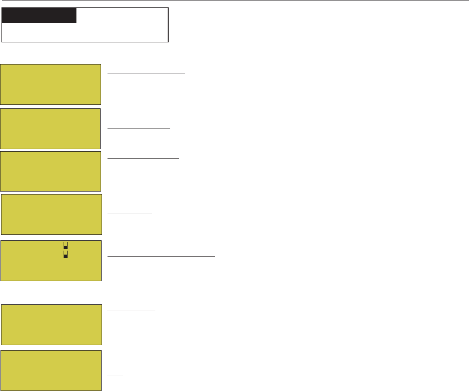
36
EasyTouch Wireless Control Panel Installation and User’s Guide
IntelliChem
To access the IntelliChem pH and ORP settings:
PH/ORP Values: Press the Right button to access the pH and OPR set point values
screen. Use the Up/Down button to adjust the pH set point value. Press the Right
button again to set the ORP set point value. Press MENU to save and return to the
previous screen.
pH Set Point: Displays the current pH set point value. The adjustable range is from 7 to
8 in increments of 0.1. The default pH set point value is 7.5.
ORP Set Point: Displays the current ORP set point value. Use the Up/Down button to
adjust the ORP set point value. The adjustable range is from 650 to 800 in increments of
10. The default ORP set point value is 700 (chlorine level of 3.0 ppm). The ORP set point
is the value that IntelliChem will try to achieve based on the actual chlorine level (ppm).
STATUS: Displays the current communication link between EasyTouch and IntelliChem
via the RS-485 cable. IChem Comm Error: Check the RS-485 communication cable is
connected to the COM port on the EasyTouch circuit board.
Level Gauge indicator: Press the Up/Down button to “fill” the gauge icon so that it
visually represents the same amount of acid available in the container. Press Up/Down
button six (6) times to fill the gauge (three times to half fill the gauge). Six horizontal bars
represent chlorine (or bromine) supply is full. One bar indicates the supply is nearly empty.
pH VAL 7.0
pH Set: 7.5
ORP VAL: 650
ORP SET: 750
IntelliChem
PH/ORP Values
Status
Sat Index
IntelliChem
PH/ORP Values
Status
Sat Index
IntelliChem
PH/ORP Values
Status
Sat Index
Clock
IntelliFlo
IntelliChlor
IntelliChem
IntelliChem provides the EasyTouch system with continual analysis of your swimming pool water sanitation
and pH levels, providing real-time status information to dispense the proper amount of muriatic acid (pH
reducer) and chlorine or bromine for the correct sanitization and pH balance. IntelliChem operates with or
without a salt chlorine generator to provide a self-replenishing supply of chlorine generated from salt. For
more information, refer to the IntelliChem Installation and User’s Guide (P/N 521363).
From the IntelliChem menu you can adjust the pH and Oxidation Reduction Potential (ORP) set point values to
meet pool and spa chemistry standards for your pool. A status screen displays a user adjustable pH and OPR
fuel gauge which visually represents the same amount of chemicals available in pH and ORP container.
Settings Menu: IntelliChem
MENU ▼ SETTINGS ▼ INTELLICHEM
Getting There
Sat Index: To access the Sat Index settings, press the Up/Down button then press the
Right button. Use the Up/Down button to adjust the levels/values for: CH (calcium
hardness), TDS (Total Dissolved Solids), TA (total alkalinity) CYA (cyanuric acid)
and TMP (current temperature). Note: See table below for ideal Saturation Index
levels.
SI: The saturation Index is displayed. IDEAL: Optimum levels. CORROSIVE: pH too
low. SCALING:
Press the Menu button three times to return to the main screen.
Note: Use the Langelier Saturation Index (LSI) Calculator to diagnose the water balance in your pool. Water with
a LSI of 1.0 is one pH unit above saturation. Reducing the pH by one unit will bring the water into equilibrium. To use
the LSI calculator, refer to: http://www.pentairpool.com/pool-owner/resources/calculators/langelier/
Recommended Pool Chemistry
ph range: 7.2 to 7.6
ORP range: 650 to 750
Alkanlinity: 80 to 120 ppm
Calcium Hardness: 200 - 500 ppm
Cyanuric Acid/Stabilizer: 30 ppm
pH Lv1:
ORP Lv1:
ICHEM: ON
ORP Dosage Limit
CH: 245 TDS: 0
TA: 75 CYA: 18
SI: NA TMP: 0
IDEAL

37
EasyTouch Wireless Control Panel Installation and User’s Guide
SAT INDEX: The Saturation Index (SI), also called the Langelier Index, is a chemical equation or formula used to
diagnose the water balance in the pool. The Saturation Index formula is SI = pH + TF + CF + AF - 12.1. To calculate
the Saturation Index, you must first test the pool water for pH, temperature, calcium hardness, and total alkalinity.
Refer to a chart for assigned values for your hardness, and alkalinity readings then add these to your pH value.
Subtract 12.1, which is the constant value assigned to Total Dissolved Solids and a resultant number will be produced.
A result between -0.3 and +0.5 indicates balanced water. Test results not within these values require chemical
adjustments to achieve balance. This formula is more or less reliable but not guaranteed. In some cases, individual
readings for pH, calcium, and alkalinity might be beyond normal recommendations, however, combined within the
formula can produce “balanced water.” The SI is useful to pinpoint potential water balance problems.
pH: pH produced by IntelliChlor SCG is close to Neutral pH. However, other factors usually cause the pH of the
pool water to rise. Therefore, the pH in a pool chlorinated by IntelliChlor tends to stabilize at approximately 7.8.
This is within APSP standards. If the pool pH rises above 7.8, have a pool professional test to see if other factors
such as high Calcium Hardness or Total Alkalinity are the cause and then balance accordingly.
pH Level Test: Test the pH level of your pool water with a reliable test method. If necessary, adjust according
to your pool professional’s recommendations. APSP’s recommended ideal range for pH is 7.4 to 7.6. Note: Never
use dry acid (sodium bisulfate) to adjust pH in arid geographic areas with excessive evaporation and minimal
dilution of pool water with fresh water. A buildup of byproducts can damage the IntelliChlor SCG
Calcium Hardness: Recommended range for calcium hardness is 200-400 ppm. Calcium Hardness levels should be
tested weekly. Calcium hardness is the calcium carbonate scale deposited on pool surfaces. The test for Calcium
Hardness is a measure of how “hard” or “soft” the water is testing. “Hard” water can have high levels of calcium
and magnesium. If these levels are too high the water becomes saturated and will leave calcium carbonate scale
deposits (a “white-ish,” crystallized rough spot) on any surface inside the pool. If the levels are too low, the water
becomes “soft” and will corrode surfaces inside the pool. Use TSP or Hydroquest 100 to lower Calcium Hardness
levels that are too high or add water to the pool which has a lower calcium hardness content. Levels which are too
low require the addition of calcium chloride.
Total Dissolved Solids (TDS): Adding salt to pool water will raise the TDS level. While this does not adversely
affect the pool water chemistry or clarity, the pool water professional testing for TDS must be made aware salt
has been added to the IntelliChlor system. The individual performing the TDS test may then subtract the salinity
level to arrive at a TDS level that would be compatible to a TDS reading for a non-salt water pool.
Total Alkalinity: APSP’s recommended ideal range for total alkalinity is 80 to 120 ppm for “gunite” and con-
crete pools and 125-170 ppm for painted, vinyl, and fiberglass pools. Test levels weekly and adjust according to
your pool professional’s recommendations. Alkalinity can be described as a buffer that keeps pH in order. pH
depends on the ability of the alkalinity in the water to withstand the changes in pH. If the alkalinity is too high,
adding acid (similar to pH) lowers the level. Adding a base (e.g sodium bicarbonate) when alkalinity is low, raises
the level. The level of alkalinity in the water is a measurement of all carbonates, bicarbonates, hydroxides, and
other alkaline substances found in the pool water.
Cyanuric Acid: Cyanuric acid is needed in outdoor pools to help to stabilize and maintain proper levels of
chlorine. 90% of unstabilized chlorine is destroyed by the UV radiation from the sun within two hours. Cyanuric
acid stabilizes chlorine in water from UV degradation. When using the IntelliChlor SCG, the cyanuric acid level
should be maintained between 30 ppm-50 ppm maximum.
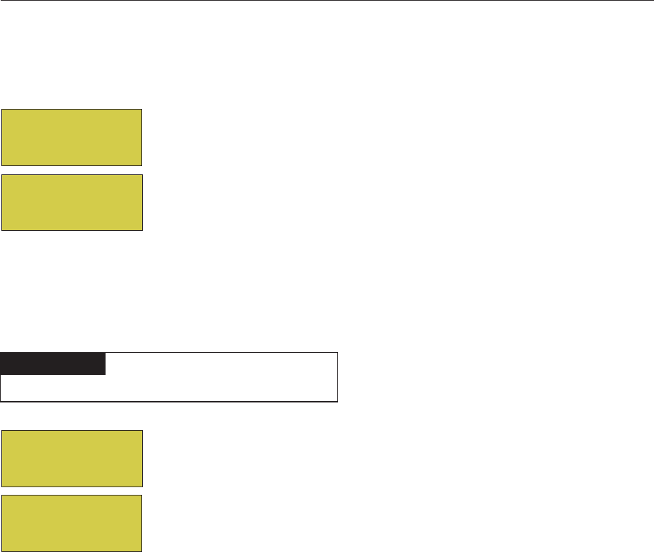
38
EasyTouch Wireless Control Panel Installation and User’s Guide
Settings Menu: Heat Pump COM (UltraTemp® Heat Pump)
Heat Pump Com screen
From the Heat Pump Com screen you can view the current UltraTemp® operation status, and set the unit to
operate with for heating only, cooling only, or both heating and cooling if the unit is reversible. Connection from
UltraTemp is via the COM PORT on the EasyTouch motherboard. See page 67 for UltraTemp to EasyTouch
COM port wiring information. The UltraTemp must be set to default ADDRESS 1. One UltraTemp unit can be
connected to EasyTouch.
Note: Once the UltraTemp is enabled, use the Left and Right arrow buttons to adjust the UltraTemp
temperature and cooling, (see page 3).
Heat Pump Com
To access Heat Pump Com (UltraTemp) settings menu:
Right button: Access the “Settings” menu.
Up/Down buttons: Select Yes or No to enable or disable UltraTemp.
Right button: Move to the “Heating” setting.
Up/Down buttons: Select Yes or No to use for heating.
Right button: Move to the “Cooling” setting.
Up/Down buttons: Select Ye s or No to use for cooling only or if the unit is
reversible select both heating and cooling.
Press the Menu button to save the settings and to return to the Heat Pump Com
Settings and Status menu options.
Press the Menu button three times to return to the main screen.
To access Heat Pump Com (UltraTemp) Status menu:
MENU ▼ SETTINGS ▼ HEAT PUMP COM STATUS
Getting There
▲
Right button: To view the current UltraTemp status.
Press the Menu button to return to the main screen.
Status
[ OP NORMAL ]
<MENU> = EXIT
Settings
Status
Heat Pump Com
Enable : Yes
Heating : Yes
Cooling : Yes
Settings
Status

39
EasyTouch Wireless Control Panel Installation and User’s Guide
Settings Menu: Circuit Names
Labeling Circuit Buttons in the EasyTouch Load Center
EasyTouch is factory configured to display each output circuit by its generic name (e.g. AUX 1, AUX 2, etc.).
These generic circuit auxiliary names can be assigned a new names which are more descriptive of the
equipment being controlled. This makes it much easier to operate all of the pool, spa and lighting equipment
without having to memorize what each output controls.
For circuit identification, adhesive backed circuit name labels are provided for placement next to each auxiliary
control panel button. Use the written list of circuit names (buttons) that you made while setting up the
EasyTouch system load center. Identify what you labeled circuit button 1, button 2 etc. The circuit names you
assign should match the labels you put on the EasyTouch load center control panel buttons and/or the optional
Indoor Control Panel buttons. Note that examples shown below use the factory set generic output names
displayed in the EasyTouch control panel menus.
Circuit Names
To assign circuit names:
Up/Down buttons: Select the circuit number 1/18. Press the Up button two times
to select AUX 1. The generic circuits names are: Spa (1/18), Pool (2/18), Aux 1-7
(EasyTouch 8), Aux 1-3 (EasyTouch 4), Ft 1. (10/18) - Ft. 8 (17/18), AuxX (18/18 -
Aux Extra). The circuit number 1/18 corresponds to its assigned circuit name. This
name can be changed to suite the function. Aux Extra is only available if the Solar
output (J17) plug on the EasyTouch motherboard is not being used for solar
equipment. Use the Solar button to switch the “extra” auxiliary circuit on and off (see
page 4).
Right button: Move to EasyTouch preset circuit names and user defined custom
circuit names.
Up/Down buttons: Scroll through the list of alphabetical programmed names. If you
cannot find a name to match your circuit, you can create your own custom name.
Repeat for all the circuit buttons that you wish to assign names to. For a complete list
of EasyTouch circuit names, see page 38.
Press the Menu button to save the settings and to return to the Settings menu
options. Press the button again to return to the main menu options or press again to
return to the main screen.
Note: After a generic circuit name is changed and saved, the new name is
displayed in the menu settings. You can view the default generic circuit names in
the menu settings before they were changed by enabling “Cir Names.” Refer to
“Diagnostics: Cir Names (Off),” on page 56.
MENU ▼ SETTINGS ▼ CIRCUIT NAMES CIRCUIT NAMES
Getting There
▲
Circuit Names
Circuit #: 3/18
Circuit : AUX 1
[AUX 1 ]
Hi-Temp/Lo-Temp Controls for Single Body System
For an EasyTouch single body system, you have the option to control your pool and spa temperature settings
using the Valves (V) button or the Spa (Hi-Temp) and Pool (Lo-Temp) button on the optional Indoor control
Panel. Change the circuit name SPA to HI-TEMP and POOL to LO-TEMP so that the display shows the correct
temperature controls for your single body system.
40
EasyTouch Wireless Control Panel Installation and User’s Guide
EasyTouch Circuit Names
AERATOR
AIR BLOWER
AUX 1
AUX 2
AUX 3
AUX 4
AUX 5
AUX 6
AUX 7
AUX 8
AUX 9
AUX 10
AUX EXTRA
BACKWASH
BACK LIGHT
BBQ LIGHT
BEACH LIGHT
BOOSTER PUMP
BUG LIGHT
CABANA LTS
CHEM. FEEDER
CHLORINATOR
CLEANER
COLOR WHEEL
DECK LIGHT
DRAIN LINE
DRIVE LIGHT
EDGE PUMP
ENTRY LIGHT
FAN
FIBER OPTIC
FIBER WORKS
FILL LINE
FLOOR CLNR
FOGGER
FOUNTAIN
FOUNTAIN 1
FOUNTAIN 2
FOUNTAIN 3
FOUNTAINS
FRONT LIGHT
GARDEN LTS
GAZEBO LTS
HIGH SPEED
HI-TEMP
HOUSE LIGHT
JETS
LIGHTS
LOW SPEED
LO-TEMP
MALIBU LTS
MIST
MUSIC
Custom Circuit Names (11 characters maximum)
USERNAME-01 ____________________
USERNAME-02 ____________________
USERNAME-03 ____________________
USERNAME-04 ____________________
USERNAME-05 ____________________
USERNAME-06 ____________________
USERNAME-07 ____________________
USERNAME-08 ____________________
USERNAME-09 ____________________
USERNAME-10 ____________________
NOT USED
OZONATOR
PATH LIGHTS
PATIO LTS
PERIMETER L
PG2000
POND LIGHT
POOL PUMP
POOL
POOL HIGH
POOL LIGHT
POOL LOW
POOL SAM
POOL SAM 1
POOL SAM 2
POOL SAM 3
SECURITY LT
SLIDE
SOLAR
SPA
SPA HIGH
SPA LIGHT
SPA LOW
SPA SAL
SPA SAM
SPA WTRFLL
SPILLWAY
SPRINKLERS
STREAM
STATUE LT
SWIM JETS
WTR FEATURE
WTR FEAT LT
WATERFALL
WATERFALL 1
WATERFALL 2
WATERFALL 3
WHIRLPOOL
WTRFL LGHT
YARD LIGHT
FEATURE 1
FEATURE 2
FEATURE 3
FEATURE 4
FEATURE 5
FEATURE 6
FEATURE 7
FEATURE 8

41
EasyTouch Wireless Control Panel Installation and User’s Guide
Settings Menu: Circuit Functions
Assigning Circuit Functions
From the “Circuit Functions” menu you can assign special logic to the cleaner pump, spa spillway, lights and
MagicStream laminar circuits. For example, when setting up an automatic pool cleaner pump, you would
assign the circuit function “MASTER CLEANER.” With this "Cleaner" logic the cleaner pump would force
the filter pump on, and the cleaner pump would start after a delay of five minutes. The cleaner pump would
automatically shut off whenever the spa and/or solar is switched on.
Freeze Protection
Freeze protection switches on a circuit if the outside air temperature sensor detects the temperature is getting
close to freezing (below 35° F). The system will switch on all circuits that have been assigned freeze
protection, and runs the circuits for 15 minutes to stop the pipes from freezing. This is especially important if
there is a pool and spa combination. If freeze protection is set to both the spa and pool circuits, the filter pump
switches on and the pool and spa valves alternate every 15 minutes to keep the water moving in both the pool
and spa. This process continues until the freeze condition is over.
Circuit Functions
To assign a circuit function and freeze protection:
Up/Down buttons: Choose the circuit name (displayed on the second line). The
generic circuits names are: Spa [Master Spa - Freeze protection on by default], Pool
[Master Pool - Freeze protection on by default], Aux 1-7 (EasyTouch 8), Aux 1-3
(EasyTouch 4), Feature 1-8 and Aux Extra. Aux Extra is only available if the Solar
output (J17) plug on the EasyTouch motherboard is not being used for solar
equipment. Use the Solar button to switch the “extra” auxiliary circuit on and off (see
page 4).
Right button: Move to the “Circuit Function” setting to select the circuit function for
the select circuit name displayed on the line above.
Up/Down buttons: Select the circuit function. This is the circuit that you wish to
assign the function logic to. For a complete list of preset circuit functions, see “Preset
Circuit Functions,” on page 38.
Right button: Move to Freeze Protection setting.
Up/Down buttons: Select Yes or No to assign freeze protection to this circuit. If
“Yes” is selected, the circuit will switch on if the air temperature drops to 35° F.
Note: for the POOL circuit the filter pump will have freeze protection. For the
SPA circuit the filter pump will run and the pool/spa valves will switch between
pool and spa at 15 minutes intervals throughout the freeze condition. For the
MASTER CLEANER circuit freeze protection is generally not needed for pool
cleaner pumps since they get water flow from the filter pump. Just make sure
that POOL has freeze protection.
Press the Menu button to save the settings and to return to the Settings menu
options. Press the button again to return to the main menu options or press again to
return to the main screen.
MENU ▼ SETTINGS ▼ CIRCUIT Func. CIRCUIT/ Func.
Getting There
▲
Circuit/Fun.
[SPA ]
[Master Spa ]
Freeze: Yes/No

42
EasyTouch Wireless Control Panel Installation and User’s Guide
Preset Circuit Functions
cireneG elbammargorpehtllahtiwtiucricafolortnocffO/nOelpmiS.cigoLlaicepsoN
.seitilibapac
apSretsaM ehtseodtI.rotautcaevlavrenaelcrospmuprenaelcloopcitamotuahtiwskroW
:gniwollof
.nosehctiwspmuprenaelcehterofebsetunim5nopmupretlifehtsecroF-
.nosiapsehtnehwfforenaelcehthctiwS-
.snigebgnitaehralosehtnehwsetunim5roffforenaelcehthctiwS-
looPretsaM ehtseodtI.rotautcaevlavrenaelcrospmuprenaelcloopcitamotuahtiwskroW
:gniwollof
.nosehctiwspmuprenaelcehterofebsetunim5nopmupretlifehtsecroF-
.nosiapsehtnehwfforenaelcehthctiwS-
.snigebgnitaehralosehtnehwsetunim5roffforenaelcehthctiwS-
renaelCretsaM ehtseodtI.rotautcaevlavrenaelcrospmuprenaelcloopcitamotuahtiwskroW
:gniwollof
.nosehctiwspmuprenaelcehterofebsetunim5nopmupretlifehtsecroF-
.nosiapsehtnehwfforenaelcehthctiwS-
.snigebgnitaehralosehtnehwsetunim5roffforenaelcehthctiwS-
thgiL .ffosthgilLLAronosthgilLLAsahcus,krowotserutaefgnithgillaicepsswollA
thgiLMAS lenaPlortnoCroodnIehtnosneercsrehtonosmargorpgnithgilroloclaicepssetavitcA
LLAronosthgilLLAevahnacuoy,elpmaxeroF.sthgilloopMAShtiwdesunehw
.ffosthgil
thgiLLAS lenaPlortnoCroodnIehtnosneercsrehtonosmargorpgnithgilroloclaicepssetavitcA
htiwdesunehwLASsthgilLLAronosthgilLLAevahnacuoy,elpmaxeroF.sthgilaps
.ffo
rotareneGnotohP detarepoebblubcitporebifskrowrebiFriatnePswollaecruosthgil®rotareneGnotohP
MAShtiwdesunehwFFOLLAdnaNOLLA,etatoR,cnySserutaefunemsthgiLehtyb
.gnithgilLASdna
leehWroloC lenaPlortnoCroodnIehtnosneercsrehtonosmargorpgnithgilroloclaicepssetavitcA
LLAronosthgilLLAevahnacuoy,elpmaxeroF.skrowrebiFriatnePhtiwdesunehw
.ffosthgil
yawllipS sevomgnittessihT.loopehtevobadesiarsiapsehterehwsnoitanibmocaps/looproF
ottisnruterdnaloopehtmorfretawehtslluppmupretlifehttahtosevlavnrutereht
sihtnehwffodenruterasrenaelcloopcitamotuA.tceffellafretawagnitaerc,apseht
.nodenrutsierutaef
renaelCroolF renaelc2neewtebwolfgnitanretlasetunim02yreveevlavyaw-3asevomgnittessihT
.sdaehpu-popehtdeeftahtsevlavmetsys
etirBilletnI .thgilDELetirbilletnInaetavitcA
maertScigaM .ranimalmaertScigaMaetavitcA

43
EasyTouch Wireless Control Panel Installation and User’s Guide
Settings Menu: Custom Names
There are nearly 100 circuit names available to choose from. If you cannot find one to fit your application you
can create up to 10 custom names. Each name can be up to 11 alphanumeric characters. After a custom name
is saved, it is then available for selection (see page 40).
Custom Name
To assign a custom circuit name:
Up/Down buttons: Select a custom circuit name number (1-10). You can create up
to 10 custom circuit names.
Right button: Move to custom circuit name setting.
Up/Down/Right buttons: Enter the custom circuit name (11 characters maximum).
Press the Menu button to save the settings and to return to the Settings menu
options. Press the button again to return to the main menu options or press again to
return to the main screen.
Settings Menu: Valves
This feature lets you assign a circuit to Valve A or B. The EasyTouch system can drive two auxiliary valve
actuators (A and B) for applications such as solar heating and water features. By assigning AUX circuits to
control valve actuators, you can conserve auxiliary circuits for high voltage relays for controlling pumps and
lights.
Valve A: Resides on the EasyTouch motherboard. If solar heating is setup and is not configured as a heat
pump, then Valve A is dedicated for controlling the solar heating valve actuator. Solar is enabled in the “Solar”
menu. The Valve A selection will display “USED SOLAR.”
Valve B: Resides on the EasyTouch motherboard. Can be configured to be controlled by any circuit.
Valves
To assign a circuit to Valve A and Valve B:
Up/Down buttons: Select a circuit to assign to Valve A. The generic circuit
selections are: The generic circuits names are: None, Spa, Pool, Aux 1-7
(EasyTouch 8), Aux 1-3 (EasyTouch 4), Feature 1-8, Solar and Heater. “Aux Extra”
is displayed only available if the Solar output (J17) plug on the EasyTouch
motherboard is not being used for solar equipment. Use the Solar button to switch the
extra circuit on and off (see page 4). Selecting “None” does not assign a circuit.
Right button: Move to Valve B setting.
Up/Down buttons: Select a circuit to assign to Valve B. See above for the generic
circuits names.
Press the Menu button to save the settings and to return to the Settings menu
options. Press the button again to return to the main menu options or press again to
return to the main screen.
MENU ▼ SETTINGS ▼ CUSTOM NAMES CSTM NAME
Getting There
▲
Cstm Name 1/10
[USERNAME-01]
MENU ▼ SETTINGS ▼ VALVES SETUP VALVES
Getting There
▲
Set Valves
A: [CLEANER ]
B: [FOUNTAIN ]

44
EasyTouch Wireless Control Panel Installation and User’s Guide
Settings Menu: 2-Speed Pump
Equipment circuits selected in this menu will automatically switch a two-speed filter pump to high speed when
these circuits are on. If a two-speed pump is assigned to solar, a cleaner or a pump, when activated the pump
will automatically run for five minutes in high speed then switch to low speed. For example, when on, the filter
pump will switch to high speed whenever the JETS or CLEANER is on. There must be a two-speed relay
installed in the EasyTouch Load Center in order for the “2-Speed Pump” menu settings to function.
2-Speed Pump
To configure a two-speed pump to a circuit:
Settings Menu: Solar
Use the solar settings to setup solar or configure solar as a heat pump: Setting Up Solar Control: Ensure
that the solar temperature sensor is installed.
About Installing Solar Heating: First, install the solar sensor at the collectors and connect to the EasyTouch
load center. If HEAT PUMP is selected and is being used in place of a solar heating system, install Solar
sensor near the EasyTouch Load Center. Connect the wires to the SOLAR screw terminals according to the
wiring diagram on page 64. Plug the solar valve actuator cable into three-pin socket marked VLV A on the
EasyTouch motherboard. If a solar booster pump is being installed, connect the pump to a power relay and
plug a low voltage cable from relay into the two-pin socket marked SOLAR on the EasyTouch motherboard.
Note: If Solar is not selected (No), the EasyTouch menu selections display “AUX EXTRA”
instead of “SOLAR.” This allows the solar plug (J17) on the EasyTouch motherboard to be used
an “extra” auxiliary output circuit. The Solar button is used to switch on and off the extra
auxiliary circuit.
To access the Solar menu:
MENU ▼ SETTINGS ▼ Solar Solar
Getting There
▲
MENU ▼ SETTINGS ▼ 2-Speed Pump 2-Speed Pump
Getting There
▲
2-Speed Pmp 1/4
Circuit:
[SPA HEATER ]
Up/Down buttons: Select a circuit that will switch the filter pump to high speed. You can set up to four circuits to use
a two-speed pump (1/4, 2/4, 3/4, 4/4).
Right button: Move to assign a circuit setting.
Up/Down buttons: Select the circuit to assign to a two-speed pump. The generic circuits names are: NONE, SPA,
POOL, AUX 1-7 (EasyTouch 8), AUX 1-3 (EasyTouch 4), FEATURE 1-8, SOLAR, HEATER, POOL
HEATER, SPA HEATER and FREEZE. AUX EXTRA is displayed only available if the Solar output (J17) plug on
the EasyTouch motherboard is not being used for solar equipment. Use the Solar button to switch the extra circuit on
and off (see page 5). Selecting NONE does not assign a circuit. Note: You can use a Feature circuit to change a 2-
Speed pump to hight speed.
Right button: Assign the next circuit (2/4).
Up/Down buttons: Select the first digit for the circuit number (1/4, 2/4, 3/4, 4/4).
Right button: Move to circuit setting.
Up/Down buttons: Select the next circuit. When finished press the Menu button.
Press the Menu button to save the settings and to return to the Settings menu options. Press the button again to return
to the main menu options or press again to return to the main screen.
Solar: Press the Up/Down button to select which solar screen to
view. Press the Right
Press the Up/Down button to select which solar screen to view. Press the Right button to select the setting and
the Up/Down button to change a setting or value.
Screen (1/3): ENABLE SOLAR: Is the pool using solar heat? Select Yes or No to enable solar heat. To display
the solar selection as a heat source in the main screen, select Ye s .
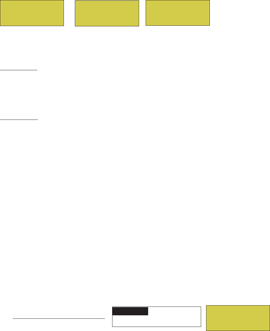
45
EasyTouch Wireless Control Panel Installation and User’s Guide
Settings Menu: Delays (Spa/Pool (Heater Cool-Down) and Delays For Valves)
Setup which functions (pool/spa, and valves) to assign the delay feature. Delays can be assigned to the
following equipment.
•Heater Cool-Down Delay Cancel: Shuts Filter Pump off immediately.
•2-Speed Filter Pump five-minute START on HIGH SPEED Delay Cancel: Shifts pump to low
speed.
•Automatic Pool Cleaner START Delay: Starts Cleaner Pump immediately, without normal delay in
which the filter pump first runs for 5 minutes.
•Automatic Pool Cleaner SOLAR Delay: Allows Cleaner Pump to run even though solar delay has
shut it off for 5 minutes.
Some heaters require a cooldown cycle before being switched off. This can be setup to run the filter pump an
additional ten minutes to dissipate residual heat built up inside the heater combustion chamber. You can also
cancel the delay feature. For information about using the cancel delay feature, refer to “Delay Cancel” on
page 24.
Delays
Cooldown: No
Valves: No
MENU ▼ SETTINGS ▼ DELAYS DELAYS
Getting There
▲
Solar 1/3
Enable: Yes
Heat Pump: No
Solar 3/3
Temperature Diff
Start: 6°
Run : 4°
Solar 2/3
Freeze Enbl: No
Night Cool : No
Press the Up/Down buttons to select YES to enable COOLDOWN delays for the pool and spa circuits.
Select YES to use delays for valves. Press the Menu button to save and to return to the Settings menu options.
HEAT PUMP: Is a heat pump being used for solar heat? Select Yes or No to enable solar as a heat pump. Heat
Pump Control instead of Solar: Select YES if a heat pump is being used in place of a solar heating system. If Solar
is set to heat pump, Valve A is free for other circuits.
Right button: Select 2 of 3 (2/3) to access the freeze and night cooling features.
Screen (2/3): ENABLE FREEZE: Enable freeze protection when using solar heat. Select Yes or No to enable
freeze solar protection.
ENABLE NIGHT COOLING: Select Yes or No to enable nocturnal cooling. Night cooling enabled (YES), will
circulate water through the system to lower the temperature during the night hours. Set the temperature in the Heat
menu. Note: If a heat pump is being used instead of a solar heating system (see above), select YES to enable solar as
a Heat pump.
Screen (3/3): Solar temperature differential start up and run settings.
Start: Set the temperature differential to start heating from 3° to 9°. For example, if “Start” is set to 3°, this ensures
that the temperature has to deviate by 3° at least to the specified set point temperature (in the Heat menu, on page 25)
before it switches on. Once the solar comes on it will start converging as it is heating. This ensures that it will not
continually be switching on and off.
Run: Set the temperature differential to stop heating from 2° to 5°. This setting sets how close to the target set point
temperature to switch off solar heat.
Press the Menu button to save the settings and to return to the Settings menu options. Press the button again to return
to the main menu options or press again to return to the main screen.
Delays: To assign a delay feature:
Delays Cooldown: This feature keeps the pump running for ten minutes after the heater is switched off to cool down the
heaters header andheat exchanger. Some heater models require this cool down period or damage will occur. This is
sometime referred toas the “Fireman Switch.” for example, If you are in the spa, and you switch it off. The IntelliTouch
will return the valvesto “Pool” mode position. If the pool is running a cycle, or the Fireman switch (Spa/Pool Delay) is
enabled,colder water from the pool would be pumped into the spa as the valves turn. Note: If the pool is not running a
cycle,and the fireman switch is not enabled, the pump stops and no pool water would be pumped into the spa as the
valvesturn back to pool. Delays For Valves: This feature creates a 30 second PUMP OFF (forced) period anytime the
valves rotate. Either from poolto spa, or spa to pool. When you switch the spa off, even if the pool is running a cycle or
the fireman switch is enabled,it stops the pump for 30 seconds while the valves turn, so colder water from the pool will
not enter the spa. This featureprevents cold water entering the spa when you start the spa, so less heating is needed. It
also stops the pump when thesystem is changing from pool to spa or back again in Freeze mode.
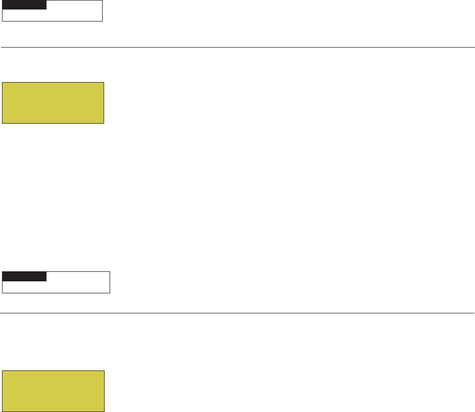
46
EasyTouch Wireless Control Panel Installation and User’s Guide
Settings Menu: F° / C° (Fahrenheit/Celsius)
The temperature settings for the water, solar and air can be displayed in either Fahrenheit or Celsius.
F° / C°
To change the temperature units:
Up/Down buttons: Select either Fahrenheit or Celsius. Press the Menu button to
save the settings and to return to the Settings menu options. Press the Menu button
again to return to the main menu options or press again to return to the main screen.
Settings Menu: iS4 Spa-Side Remote Controller
You can specify any iS4 Spa-Side remote button to control different functions by assigning each button to a
specific circuit. For example, you can use the iS4 Spa-Side remote to activate the spa circulation and for
operating auxiliary equipment such as heater, lights, jet pump, heat boost, air blower, waterfall, etc.). You can
also use the “Pump Incrs” and “Pump Decrs” circuit to increase or decrease the pump speed for an IntelliFlo
VF (GPM) or VS (RPM) pump. For example, if the “Pump Incrs” circuit is assigned to an iS4 button, each
press of the button will increase the pump speed in specific speed increments as specified in the “iSx Pump
Cntrl” menu setting (see page 44). Speed increments are set from 10 to 250 RPM (or 1 to 10 GPM, for the
IntelliFlo VF).
Assign iS4
Before configuring the iS4 Spa-Side remote controller assign names to the circuits (see page 42).
To assign iS4 Spa-Side buttons:
Up/Down buttons: Select a circuit to one of the iS4 buttons. You can set up to four
circuits (1/4, 2/4, 3/4, 4/4).
Right button: Move to the circuit setting.
Up/Down buttons: To configure the first button on the iS4 Spa-Side Remote, scroll
through the circuit names and find the circuit that you would like to assign to the first
button on the iS4. The generic circuits selections are: None, Spa, Pool, Aux 1-7
(EasyTouch 8), Aux 1-3 (EasyTouch 4), Feature 1-8, Solar (if selected in “Heat”
menu), Heat Boost, Heat Enable, Pump Incrs, Pump Decrs. “Aux Extra” is displayed
only available if the Solar output (J17) plug on the EasyTouch motherboard is not
being used for solar equipment. Use the Solar button to switch the extra circuit on and
off (see page 4). Selecting “None” does not assign a circuit.
Note: The “Heat Boost” feature will switch on the heater for seven minutes to
increase the spa water temperature. Each time the spa Heat Boost button is
pressed, the temperature will increase about 1° F. The temperature will not go
beyond the 104° F limit.
Right button: Assign the next circuit (2/4).
Up/Down buttons: Select the first digit for the circuit number (1/4, 2/4, 3/4, 4/4) and
repeat the procedure for the other three buttons.
Press the Menu button to save the settings and to return to the Settings menu
options. Press the button again to return to the main menu options or press again to
return to the main screen.
MENU ▼ SETTINGS ▼ IS4 ASSIGN IS4
Getting There
▲
F° / C°
FAHRENHEIT
MENU ▼ SETTINGS ▼ F˚ / C˚ F˚ / C˚
Getting There
▲
Assign iS4
Circuit: 1/4
[HEAT BOOST ]
Note: To disable
or enable the
iS4 Spa-Side
remote, see
Settings Menu:
Spa Side,” on
page 53.
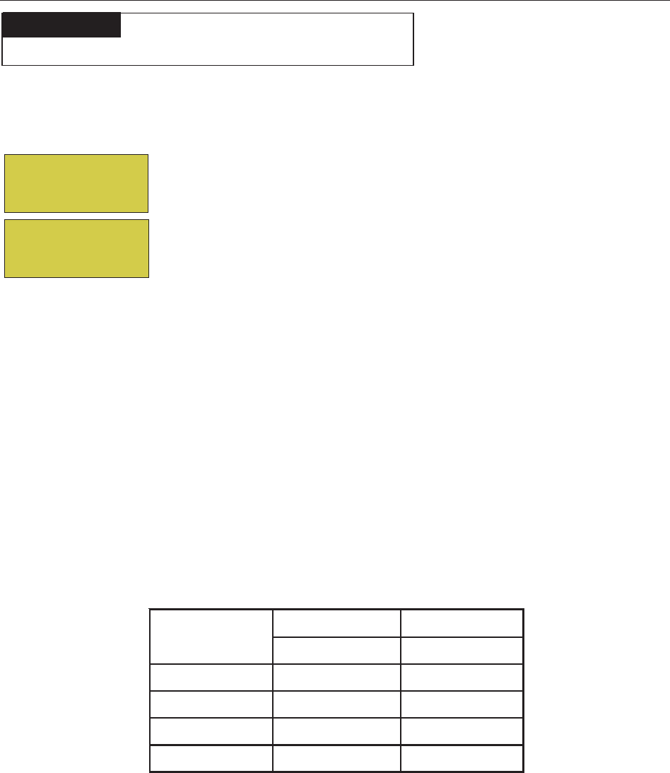
47
EasyTouch Wireless Control Panel Installation and User’s Guide
1nottuB APSLOOP
PMET-IHPMET-OL
2nottuB 1XUA5XUA
3nottuB 2XUA6XUA
4nottuB 3XUA7XUA
5nottuB 4XUA8XUA
Settings Menu: 10 Button Spa-Side Remote Controller
From this menu you can assigning a specific circuit to any one of the ten buttons of an iS10 and SpaCommand
spa-side remote to control different pool/spa functions. The iS10 and SpaCommand has ten assignable circuit
buttons; five button on the top row and five buttons on the bottom row. You can also use the “Pump Incrs” and
“Pump Decrs” circuit to increase or decrease the pump speed for an IntelliFlo VF (GPM), VS (RPM) and
VSF (RPM/GPM) pump. For example, if the “Pump Incrs” circuit is assigned to an iS10 button, each press of
the button will increase the pump speed in specific speed increments as specified in the “10B Pump Cntrl”
menu setting (see page 48). Speed increments are set from 10 to 250 RPM (or 1 to 10 GPM, for the
IntelliFlo VF).
Assign 10 Button Spa Side Remote (iS10/SpaCommand)
Before configuring the 10 button spa-side remote controller (iS10/SpaCommand) assign names to the circuits
(see page 41).
To assign an iS10 and SpaCommand spa-side remote buttons:
Up/Down buttons: Select the “Top” or Bottom” row to assign circuits to.
Right buttons: Select a circuit to one of the iS10 buttons. Five top row buttons can
be assigned circuits (1/5, 2/5, 3/5, 4/5 and 5/5). See “iS10/SpaCommand button
assignments” below for details.
Right button: Move to the circuit setting.
Up/Down buttons: To configure the first button on the iS10 Spa-Side Remote, scroll
through the circuit names and find the circuit that you would like to assign to the first
button on the iS4. The generic circuits are: NONE, SPA, POOL, AUX 1-7
(EasyTouch 8), AUX 1-3 (EasyTouch 4), FEATURE 1-8, AUX EXTRA (or
SOLAR if selected in “Heat” menu), HEAT BOOST and HEAT ENABLED.
“Aux Extra” is displayed only available if the Solar output (J17) plug on the
EasyTouch motherboard is not being used for solar equipment. Use the Solar button to
switch the extra circuit on and off (see page 5). Selecting “None” does not assign a
circuit.
Note: The “Heat Boost” feature will switch on the heater for seven minutes to
increase the spa water temperature. Each time the spa Heat Boost button is
pressed, the temperature will increase about 1° F. The temperature will not go
beyond the 104° F (40° C) limit.
Right button: Assign the next circuit (2/5).
Up/Down buttons: Select the first digit for the circuit number (1/5, 2/5, 3/5, 4/5) and
repeat the procedure for the other three buttons.
Press the Menu button to save the settings and to return to the Settings menu
options. Press the button twice to return to the main screen.
MENU ▼ SETTINGS ▼ 10 BUTN SPA SD ASSIGN 10 BUTN
Getting There
▲
iS10 and SpaCommand button assignments
Assign 10 BtnSS
Row : Top
Circuit : 1/5
[SPA ]
IS4
10 BUTN SPA SD
10B Pump Cntrl
Quick Touch
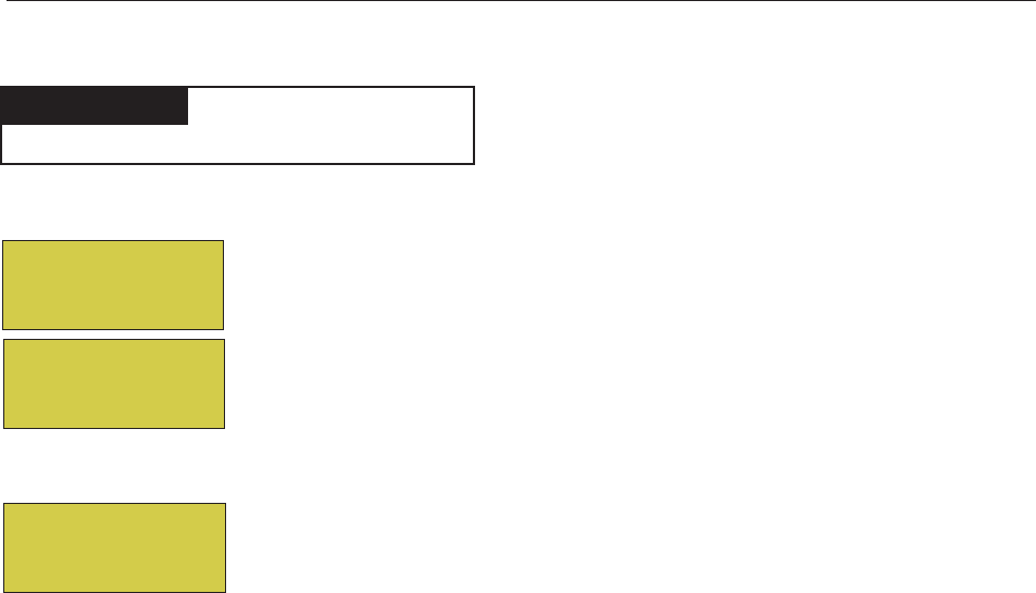
48
EasyTouch Wireless Control Panel Installation and User’s Guide
Settings Menu: 10 Button Pump Cntrl
From this menu setting you can specify the IntelliFlo VS, VF and VSF pump speed (RPM, GPM) in step
increments, for the assigned iS4, iS10 or SpaCommand button using the “Pump Incrs” or “Pump Decrs”
circuit. For example, the “Pump Incrs” and “Pump Decrs” circuit can be assigned to any two iS10 buttons.
Each press of the assigned “increase” button will increase the pump speed in specific speed increments, as
specified in the “iSx Pump Cntrl” menu setting. Speed increments are set from 10 to 250 RPM or 1 to 10
GPM.
Assign iSx Pump Cntrl
Before setting the pump step speed, be sure to specify the IntelliFlo pump number and type in the IntelliFlo
menu (“Pump #1, Pump #2,” Pump Type), see page 31.
To set a pump step speed:
Up/Down buttons: Select the “Pump Number” as specified in the IntelliFlo menu
(see page 33).
Right buttons: Select the pump “Step” speed (RPM/GPM).
Up/Down buttons: Adjust the “Step” pump speed. Settings are:
- IntelliFlo VS: 10 to 250 RPM
- IntelliFlo VSF: 10 to 250 RPM or 1 to 10 GPM
- IntelliFlo VF: 1 to 10 GPM.
Press the Menu button to save the settings and to return to the Settings menu
options. Press the button twice to return to the main screen.
MENU ▼ SETTINGS ▼ 10B PUMP CNTRL
Getting There
▲
Spa Side Pump#1
IFlo Control
Step RPM: 060
Size
Spa Side Pump#2
IFlo Control
Step RPM: 060
Size GPM: 010
IS4
10 BUTN SPA SD
10B Pump Cntrl
Quick Touch
Pump #2: IntelliFlo VSF (RPM and GPM)

49
EasyTouch Wireless Control Panel Installation and User’s Guide
Settings Menu: QuickTouch (QT4) Wireless Remote
The QuickTouch QT4 wireless remote controller provides switching of up to four circuits. For example, you
can use the QT4 wireless remote to activate the spa circulation, and for operating three auxiliary pieces of
equipment (such as heat enabled, lights, jet pump, heat boost, air blower, waterfall, etc.).
Each of the four functions on the QT4 wireless controller has an on and an off button. To switch a circuit on
or off, press and hold the appropriate button for at least a full second.
The QT4 buttons can be assigned to any available circuit. However, the QT4 has the following preset circuits
assigned to the four buttons:
• Spa button activates the spa circuit.
• A button activates Auxiliary 1 circuit.
• B button activates Auxiliary 2 circuit.
• C button activates Auxiliary 3 circuit.
Assign QT4
To assign circuits to the QuickTouch wireless controller buttons:
Up/Down buttons: Select a circuit to assign to one of the QuickTouch wireless
remote buttons. You can set up to four circuits (1/4, 2/4, 3/4, 4/4).
Right button: Move to the circuit setting.
Up/Down buttons: To configure the first button (1/4) on the QuickTouch wireless
remote. Use these buttons to scroll through the circuit names and find the circuit that
you would like to assign to the first button. The generic circuits selections are: None,
Spa, Pool, Aux 1-7, Feature 1-8 (EasyTouch 8), Aux 1-3, Feature 1-4 (EasyTouch 4),
Aux Extra, Heat Boost and Heat Enable. Selecting “None” does not assign a circuit.
“Aux Extra” is only available if the Solar output (J17) plug on the EasyTouch
motherboard is not being used for solar equipment. Use the Solar button to switch the
“extra” auxiliary circuit on and off (see page 4).
Note: The “Heat Boost” feature will switch on the heater for seven minutes to
increase the spa water temperature. Each time the spa Heat Boost button is
pressed, the temperature will increase about 1° F. The temperature will not go
beyond the 104° F limit.
Right button: Assign the next circuit (2/4).
Up/Down buttons: Select the first digit for the circuit number (1/4, 2/4, 3/4, 4/4),
then repeat the procedure for the other three buttons.
Press the Menu button to save the settings and to return to the Settings menu
options. Press the button again to return to the main menu options or press again to
return to the main screen.
MENU ▼ SETTINGS ▼ QUICKTOUCH ASSIGN QT4
Getting There
▲
Assign QT4
Circuit: 1/4
[SPA ]

50
EasyTouch Wireless Control Panel Installation and User’s Guide
Settings Menu: Man Heat (Off/On)
By default manual heat (Man Heat) is set to “On,” which allows your spa to begin to heat whenever it is
manually switched on, (by pressing the Valves (V) button and Filter Pump (F) button on the outdoor control
panel or the Spa button on the Indoor Control Panel), even if the Heat menu setting is set to “OFF” (see page
23). Your spa will also begin to heat when switched on by the iS4 Spa-Side remote. This feature allows you to
program your spa to filter daily with the heater set to off, and then be ready to heat whenever the Spa button is
pressed manually.
Man Heat
To enable or disable spa manual heat when switched on manually:
Right button:: Select Off to disable or On to automatically begin spa heating
whenever the spa is switched on manually.
Press the Menu button to save the settings and to return to the main screen.
Settings Menu: Calibration
The EasyTouch system includes two temperature sensors (10 kΩ) for water and ambient air temperature. You
can also add an additional sensor for controlling solar heating systems. Generally, these sensors are accurate
and you do not have to calibrate them. However, long plumbing runs and water features can cause
temperatures at a body of water to be different from the temperature sensor reading. You can manually
recalibrate the sensors to adjust for this. You only need to calibrate one body of water, since the temperature
sensor is common to both the pool and spa. The system must be in “Service” mode to calibrate sensors (see
“Mode” button on the EasyTouch outdoor control panel).
Calibration
Before you start, you need an accurate all weather thermometer. If you are calibrating the air sensor, wait until
the sensor is not in direct sunlight. For the air temperature sensor, make sure that the sensor is located in the
shade for accurate readings.
To calibrate the water, air and solar temperature sensors:
1. Press the Mode button on the control panel to place the system in “Service” manual mode.
2. Press the Filter Pump (F) button to switch on the pool/spa filter pump.
3. Place the thermometer in the spa or pool water. Take an accurate temperature reading. When
calibrating the air sensor, place the thermometer next to the air sensor. The air sensor is normally
located near or under the EasyTouch load center enclosure, not inside the
enclosure. Take an accurate temperature reading in the shade.
4. Use the Up or Down buttons to raise or lower the water temperature to
match the corresponding thermometer temperature reading.
5. After calibrating the water sensor, use the Right button to move to the
“AIR” setting and repeat step 4 and repeat the procedure for the solar
sensor. Ensure that the solar sensor is in the sun for accurate readings.
6. After calibrating all the sensors, press the Menu button to save the settings and to return to the
Settings menu options. Press the button again to return to the main menu options or press again to
return to the main screen.
MENU ▼ SETTINGS ▼ CALIBRATION CALIBRATION
Getting There
▲
Calibration
Water: 70°F
Air: 80°F
Solar: 90°F
10B Pump Cntrl
QuickTouch
Man Heat [On]
Calibration
MENU ▼ SETTINGS ▼ MAN HEAT [On/Off]
Getting There
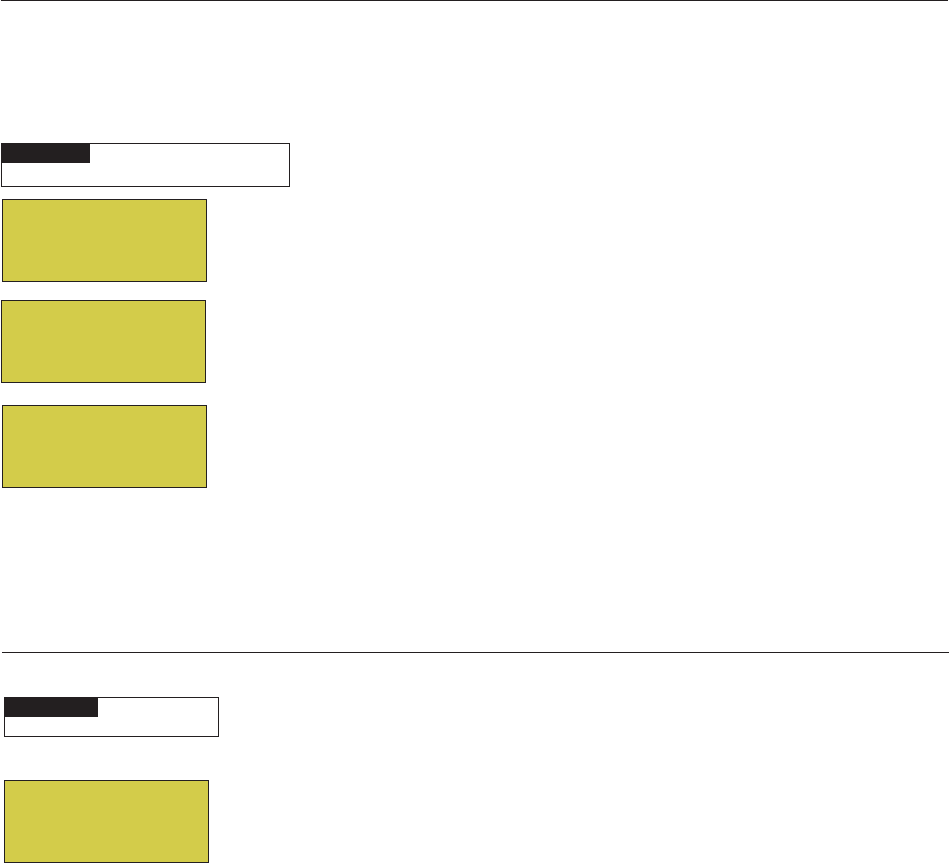
51
EasyTouch Wireless Control Panel Installation and User’s Guide
Settings Menu: Set Password
If required, the password feature allows you to password protect the EasyTouch control panel. To access a
password protected control panel, you must enter the correct four digit password before access is granted.
Password
To enable the password protect feature:
Up/Down button: Select the password first digit (0-7) of the four digit password.
Right button: Select the next password digit. Repeat the previous step to enter each
of the password digits.
Right button: After you are finished entering the four password digits, press the
Right button to enable the password feature.
Up/Down button: Select Ye s enable the password feature.
Press the Menu button three times to save the settings and to return to the main
screen.
Note: If the password feature is enabled, the current four digit password can be
viewed from the EasyTouch outdoor control panel in the “Set Password” setting.
MENU ▼ SETTINGS ▼ SET PASSWORD
Getting There
Set Password
PW : [0000]
Enable : No
Settings Menu: Erase EEPROM (Erase System Memory)
EasyTouch system configuration data is stored and retained in “Flash” memory in an EEPROM located on the
control panel motherboard and optional Indoor Control Panel. The EasyTouch user system configuration data
can be erased to restore the factory defaults settings. System information automatically downloads from
programmed components to non-programmed components in case of accidental memory loss and to ease
board replacement. Any optional controllers (iS4, iS10, SpaCommand or QuickTouch QT4 controller) that
were configured need to be reconfigured.
Erase EEPROM
The following procedure describes how to erase the system memory from either the main EasyTouch control
panel or the EasyTouch Indoor Control Panel.
CAUTION: This procedure will erase all system settings. Any optional controllers will need to be
reconfigured.
Up/Down button: Select Yes .
Right button: The message “Erase EEPROM Are You Sure? No” is displayed.
Up/Down button: Select Yes .
Right button: Press this button to erase system data and restore the factory
defaults. The display will go blank, then the main screen will be displayed.
MENU ▼ SETTINGS ▼ Erase EEPROM Erase EEPROM
Getting There
▲
Erase EEPROM
Erase ALL? No (Yes)
Erase EEPROM
Are You Sure?
No (Yes)
AUTO HEATER
SPA 95°F / 100°F
AIR 70°F
MON 09:30 AM
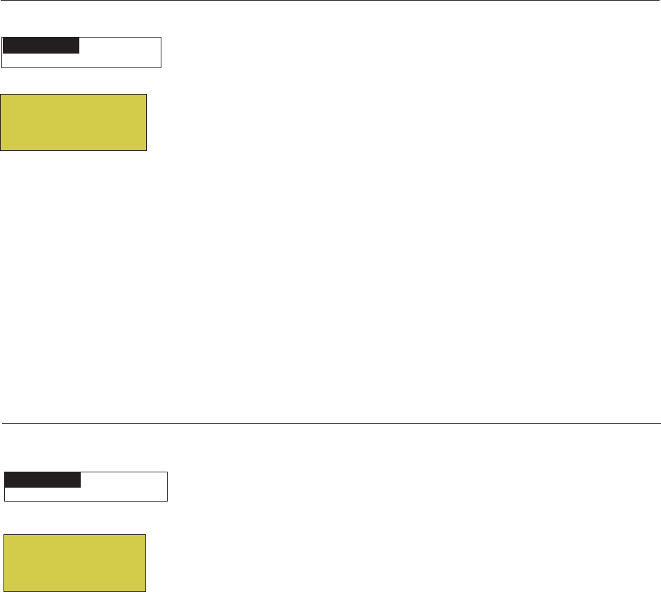
52
EasyTouch Wireless Control Panel Installation and User’s Guide
Settings Menu: Backlight
Use the backlight “On Time” option to set the duration that the backlight will stay on. The “Brightness” setting
allows you to set the backlight brightness. These options can help to reduce power consumption and extend
battery life. The Backlight options are:
•On Time: Backlight will stay on for 60 seconds, 30 seconds, five minutes, or “Backlight” feature is
off . The default setting is 30 seconds.
•Brightness: Backlight brightness can be set to low, medium or high. The default setting is medium.
Backlight
To set the backlight duration and brightness:
Up/Down buttons: Select 5 S, 15 S, 30 S, 60 S, 5 M or OFF for the backlight to
stay on.
Right button: Select LOW, MED or HI for the backlight brightness setting.
Press the Back button to save the settings and to return to the previous screen.
MENU ▼ SETTINGS ▼ BACKLIGHT
Getting There
BACKLIGHT OPTIONS
On Time: 30 S
Brightness: MED
Settings Menu: Power Save
This option sets the time that the EasyTouch wireless control panel will shut down if there is no control panel
activity. Use the power save options to reduce power consumption and extend battery life. The options are:
•Power save: Set the power save time to 15, 30, or 60 seconds, or five minutes before the unit shuts
down. The default time is 60 seconds.
Note: If the unit is not used for 60 (default) seconds the power save function switches off the unit. To
switch the unit on, press the “POWER ON” button (see page 4).
Idle Time
To set the idle time for the EasyTouch wireless control panel:
Right or Up/Down buttons: Select 30 S, 60 S or 5 M.
Press the Back button to save the settings and to return to the previous screen.
POWER SAVE
IDLE TIME: 60 S
MENU ▼ SETTINGS ▼ POWER SAVE
Getting There
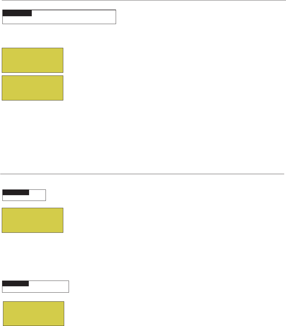
53
EasyTouch Wireless Control Panel Installation and User’s Guide
Settings Menu: Wireless Addr
Use this feature to configure the EasyTouch wireless control panel with a unique communication address to
allow the wireless device to operate with the EasyTouch outdoor control panel (see page 11).
Wireless Addr
To search and lock on to the EasyTouch wireless control panel:
Right button: Press this button to automatically search and lock on to the EasyTouch
Wireless Control Panel within range of the EasyTouch transceiver antenna. For more
information about the EasyTouch wireless control panel, refer to the EasyTouch
Wireless Control Panel User’s Guide (P/N 520688).
Press the Menu button to save the settings and to return to the Settings menu
selections.
Spa Side [Off/On]
Enable or disable the iS4 Spa Side remote. This feature is useful for families with young children or when you
go on vacation. It allows you to switch off the iS4 Spa Side remote at the control panel so that the remote
cannot be used.
Spa Side
To enable or disable the iS4 Spa Side remote:
Right button: Select On or Off to enable or disable the spa side remote.
Press the Menu button to save the settings and to return to the main screen.
Diagnostics Menu: Software Rev
Displays the current software revision for the EasyTouch main control panel and the optional indoor control
panel.
UIC: Displays the current software revision level for the indoor control panel.
UOC: Displays the current software revision level for the outdoor control panel.
Press the Menu button to return to the Settings menu options. Press the button again
to return to the main menu options or press again to return to the main screen.
MENU ▼ DIAGNOSTICS ▼ SOFTWARE REV
Getting There
Software Rev
UIC: 1.02
UOC: 1.02
MENU ▼ SPA SIDE [On/Off]
Getting There
Delay Cancel
Schedules
Settings
Spa Side [On ]
Address Wireless
Sending Address..
<MENU>
Address Wireless
Scanning ...
MENU ▼ SETTINGS ▼ WIRELESS ADDR Press Right arrow button
Getting There
▲

54
EasyTouch Wireless Control Panel Installation and User’s Guide
Diagnostics Menu: Self Test
Tests the control panel LCD and buttons. Follow the on-screen prompts to perform the tests.
Note: If the Indoor Control Panel is connected to the EasyTouch outdoor control panel, select “LINK
CLOSED” in the UART test to abort the UART test. This allows the test to complete with and display
PASSED.
Press the Right button to display the current software and boot loader revision levels
for the EasyTouch outdoor control panel.
Press the Right button to start the test:
Press the Right button to start the test:
Display Test: Press any button to start the LCD test.
Backlight Test: Press the Left then Right button.
Contrast Test: Press any button to continue.
LED Test: Press any button to continue. All of the button LEDs will be tested.
Switch Test: Press any button to continue. As prompted, press the appropriate
buttons.
UART Test: Select “LINK CLOSED” to abort this test if the optional Indoor
Control Panel is connected to the EasyTouch load center.
Status: Passed - Code 0: After you have completed the test an error code is
displayed. “Passed” is displayed if the test was successful. For error code
descriptions, see “Self Test Error Codes,” on page 58.
Press the Menu button to return to the Settings menu options. Press the button again
to return to the main menu options or press again to return to the main screen.
MENU ▼ DIAGNOSTICS ▼ SELF TEST
Getting There
Backlight On
<=Backlight On
>=Backlight Off
Contrast:
Press any button
LED Test
Switch Test
Press any button
UART Test
<=Link Closed
>=Link Open
Press Any Button
Firmware Version
Soft: 1.02
Boot: 1.02
Press Any Button
Diagnostics Menu: Bootloader Rev
Displays the current bootloader revision for the indoor control panel and the main EasyTouch control panel.
UIC: Displays the current bootloader revision level for the indoor control panel.
UOC: Displays the current bootloader revision level for the outdoor control panel.
Press the Menu button to return to the Settings menu options. Press the button again
to return to the main menu options or press again to return to the main screen.
MENU ▼ DIAGNOSTICS ▼ BOOTLOADER REV
Getting There
Bootloader Rev
UIC: 1.02
UOC: 1.02
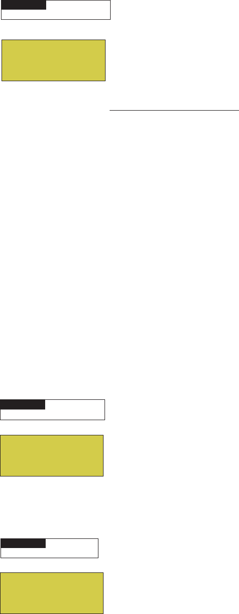
55
EasyTouch Wireless Control Panel Installation and User’s Guide
Diagnostics Menu: Chlorinator
Displays the current IntelliChlor chlorination system status. For more information, refer to the IntelliChlor
Electronic Chlorine Generator User’s Guide (P/N 520589).
Menu: Press this button to return to the Settings menu options. Press the button
again to return to the main menu options or press again to return to the main screen.
SALT LEVEL: Displays the current salt level. Values from 0 to 12750 ppm in 50 ppm
increments.
IntelliChlor Status messages:
SUPER CHLORINATE: IntelliChlor is in “Super Chlorination mode (see page 33 for
details)
COM LINK ERROR: Check cable from IntelliChlor to EasyTouch motherboard.
Check FLOW/PCB: Check IntelliChlor electrolytic cell controller. Refer to IntelliChlor
User’s Guide troubleshooting information.
LOW SALT: Add salt to pool water. The water salt level is between 2500 ppm and
2900 ppm. The IntelliChlor will continue to produce chlorine at a reduced level.
VERY LOW SALT: Not enough salt in pool. The water salt level has fallen below 2500
parts per million (ppm). IntelliChlor will not produce chlorine until additional salt is
added manually.
HIGH CURRENT: Check IntelliChlor electrolytic cell controller. Refer to IntelliChlor
User’s Guide troubleshooting information..
CLEAN CELL!!: Cell has calcium build up and requires cleaning. Refer to IntelliChlor
User’s Guide for cleaning instructions.
LOW VOLTAGE: Check IntelliChlor electrolytic cell controller. Refer to IntelliChlor
User’s Guide troubleshooting information.
OK - NO ERRORS: IntelliChlor is in normal operating mode.
Diagnostics Menu: Water Temp
Displays the current water temperature for the pool and spa.
Press the Menu button to return to the Settings menu options. Press the button again
to return to the main menu options or press again to return to the main screen.
Diagnostics Menu: Solar Temp
Displays the current solar temperature.
Press the Menu button to return to the Settings menu options. Press the button again
to return to the main menu options or press again to return to the main screen.
MENU ▼ DIAGNOSTICS ▼ WATER TEMP
Getting There
SPA ▼ DAGNOSTICS ▼ SOLAR TEMP
Getting There
MENU ▼ DIAGNOSTICS ▼ CHLORINATOR
Getting There
Chlorinator
Salt Level:3200ppm
Status:
[OK-NO ERRORS]
Solar Temperature
85° F
Water Temperature
75° F

56
EasyTouch Wireless Control Panel Installation and User’s Guide
Diagnostics Menu: Reset System
Reinitialize the Outdoor Control Panel. Resetting the Outdoor Control Panel will not effect the system
configuration settings.
Right button: Press the Right button to reset system. The main screen will be
displayed and communication will be established with the optional EasyTouch Indoor
Control Panel if installed.
Diagnostics Menu: Flash Update
Use this feature to update the EasyTouch Outdoor Control Panel firmware. The EasyTouch motherboard must
be connected to a personal computer (PC) in order to update the firmware.
Press the Menu button to exit the flash mode.
Air Temp
Disp codes
Cir Names [Off]
Reset System
MENU ▼ DIAGNOSTICS ▼ RESET SYSTEM
Getting There
MENU ▼ DIAGNOSTICS ▼ FLASH UPDATE
Getting There
Diagnostics Menu: Air Temp
Displays the current outside air temperature.
Press the Menu button to return to the Settings menu options. Press the button again
to return to the main menu options or press again to return to the main screen.
Diagnostics Menu: Cir Name: [Off/On]
This feature is useful if you have renamed many circuits and want to view the original factory default circuit
names.
To enable:
Right button: Select On to view the factory default circuit names.
Press the Menu button to exit.
To disable:
Right button: Select Off to disable the feature.
Press the Menu button to exit.
MENU ▼ DIAGNOSTICS ▼ AIR TEMP
Getting There
Air Temperature
72° F
Solar Temp
Air Temp
Disp codes
Cir Names [Off]
MENU ▼ DIAGNOSTICS ▼ CIR NAMES [OFF]
Getting There

57
EasyTouch Wireless Control Panel Installation and User’s Guide
Section 3
Troubleshooting
Troubleshooting
Use the following troubleshooting information to help resolve problems that may occur when using the
EasyTouch system. If by following the recommended actions you are still unable to resolve the problems,
please contact Technical Support (see page vi).
Frequently Asked Questions (FAQ)
How do I setup a two-speed pump?
A two-speed pump operates using two relays and one or more circuits. The first relay turns the pump on or
off. Assuming this is a filter pump, this circuit is controlled by the pool and spa circuits or any other circuit that
may be tied to the filter pump (such as circuits with freeze protection, etc.). The second relay switches the
pump from low speed to high speed. The default condition is low speed. Up to seven circuits (EasyTouch 8),
three circuits (EasyTouch 4) may be assigned to trigger the pump to high speed. Note: These circuits do not
switch the pump on.
To configure a two-speed pump relay, refer to “Settings Menu: 2-Speed Pump,” on page 44. For relay location
and wiring (see page 62). The 2-Speed pump relay connector is plugged into the 2-SPD output on the
EasyTouch motherboard.
Can I switch the heater on and change the temperature from the spa?
The heater may be switched on from the spa location using the iS4 Spa-Side remote or by the QuickTouch
wireless remote controller. To learn more about these remotes and controllers, see page v. However, the iS4
and QuickTouch wireless remote controller cannot adjust the water temperature.
How do I switch on solar heating?
The system must first be configured for solar heating. Go to the “Heat” menu (see page 23) and enable
“Solar” as the heat source (Settings Menu: Heat > Solar). Note: Do not set solar as a heat pump. Then the
heating method must be selected for each body of water.
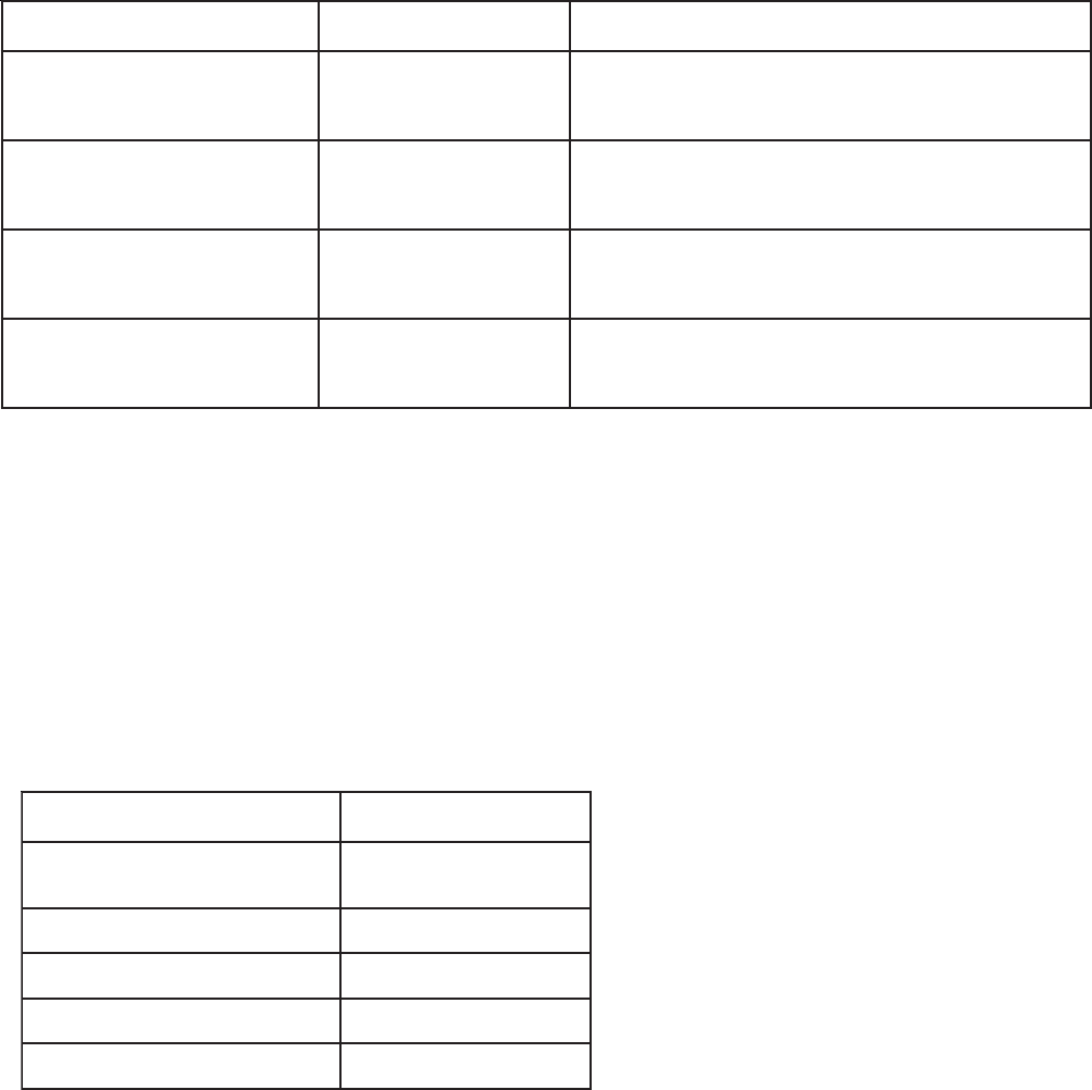
58
EasyTouch Wireless Control Panel Installation and User’s Guide
egasseMrorrEesuaCelbissoPnoituloS
niaMehtnosyalpsiD(rrEriA
)neercS
detcennoctonrosnesriA
hcuoTysaEehtot
.draobrehtom
12JotdetcennocsigulprosnesriaehttahtkcehC
rosnesehttahtkcehC.draobrehtomehtnorotcennoc
.ylreporpdetcennocsieriw
nisyalpsiD(rrEerutarepmeTriA
)unem"scitsongaiD"eht
detcennoctonrosnesriA
hcuoTysaEehtot
.draobrehtom
12JotdetcennocsigulprosnesriaehttahtkcehC
.draobrehtomehtnorotcennoc
syalpsiD(rrEerutarepmeTretaW
)unem"scitsongaiD"ehtni
tonrosnesretaW
ehtotdetcennoc
.draobrehtomhcuoTysaE
12JotdetcennocsigulprosnesretawehttahtkcehC
.draobrehtomehtnorotcennoc
syalpsiD(rrEerutarepmeTraloS
)unem"scitsongaiD"ehtni
tonrosnesraloS
ehtotdetcennoc
.draobrehtomhcuoTysaE
12JotdetcennocsigulprosnesralosehttahtkcehC
.draobrehtomehtnorotcennoc
EasyTouch Error Messages
Error Messages
If the system detects that a sensor is not connected to the EasyTouch load center or it is defective, an error
message is displayed in the “Diagnostics” menu. The following lists the sensor errors.
Self Test Error Codes
The “Self Test” feature is intended for use by service personnel. If after performing a control panel self test
(see page 54) there were no errors detected, Code 0 is displayed, indicating that there were no problems and
the test was successful. If a problem is detected during the test, an error code is displayed upon completion of
the test. For example Code 3 would indicate a problem with the LEDs on the control panel. If multiple errors
are detected, multiple code numbers are displayed. For example, Codes 4, 2, 1, would indicate problems
detected with the buttons, LEDs, and the LCD backlight on the control panel.
The following lists the control panel self test error codes.
Error Code Table
edoCrorrEnoitpircseD
0edoClenaplortnocehT-SSAP
smelborponsah
1edoCthgilkcabDCL
2edoCtsartnocDCL
3edoCsDEL
4edoC)snottub(hctiwS

59
EasyTouch Wireless Control Panel Installation and User’s Guide
egasseMsutatSesuaCelbissoPnoituloS
SRORREON-KOlamronrolhCilletnI
.edomgnitarepo
A/N
ETANIROLHCREPUSrepuS"nisirolhCilletnI
42rofedom"noitanirolhC
.sruoh
33egapees(edomnoitanirolhCrepuS“nisirolhCilletnI
)sliatedro
RORREKNILMOCnoitacinummocrolhCilletnI
hcuoTysaEhtiwrorre
.draobrehtom
.draobrehtomhcuoTysaEotrolhCilletnImorfelbackcehC
BCP/WOLFKCEHCrolhCilletnIkcehC
.lleccitylortcele
gnitoohselbuortediuGs’resUrolhCilletnIotrefeR
.noitamrofni
TLASWOL.retawloopottlasddA .mpp0092dnampp0052neewtebsileveltlasretawehT
ataenirolhcecudorpoteunitnoclliwrolhCilletnIehT
.sliatedrofediuGs'resUrolhCilletnIeeS.leveldecuder
TLASWOLYREV.loopnitlashguonetoN repstrap0052wolebnellafsahleveltlasretawehT
litnuenirolhcecudorptonlliwrolhCilletnI.)mpp(noillim
s'resUrolhCilletnIeeS.yllaunamdeddasitlaslanoitidda
.sliatedrofediuG
TNERRUCHGIHrolhCilletnIkcehC
.lleccitylortcele
otrefeR.rellortnoclleccitylortcelerolhCilletnIkcehC
.noitamrofnignitoohselbuortediuGs’resUrolhCilletnI
!!LLECNAELCpudliubmuiclacsahlleC
.gninaelcseriuqerdna
otrefeR.gninaelcseriuqerdnapudliubmuiclacsahlleC
.snoitcurtsnigninaelcrofediuGs’resUrolhCilletnI
EGATLOVWOLrolhCilletnIkcehC
.lleccitylortcele
gnitoohselbuortediuGs’resUrolhCilletnIotrefeR
.noitamrofni
Maximum Programs Exceeded
The “Maximum Programs Exceeded” message displays in the “Schedules” menu if you try to create a new
program after exceeding the 12 program limit. To create a new program you must first delete an existing
program. For information about deleting a program, refer to “Schedule Menu” on page 25.
IntelliChlor Error Messages
IntelliChlor status and error messages are displayed in the “Chlorinator” menu (see page 55). Use the
following information to resolve IntelliChlor system problems. To access the IntelliChlor menu, press
Menu > Diagnostics > Chlorinator.

60
EasyTouch Wireless Control Panel Installation and User’s Guide
Problem: iS4 fails to operate.
System Problem Diagnosis
Use the following information to resolve system problems.
Problem: The system works in Service Mode, but Indoor Control Panel fails to operate.
motpmySesuaCelbissoPnoituloS
onsahlenaPlortnoCroodnI
,sDELon,knalb,neercs(-rewop
.)gnikrowtonsnottub
morfnurgniriwdaB
lortnoCroodtuO
ehtnidraobrehtom/lenaP
.retneCdaoL
nI.nekorberasnoitcennoconerusnednaelbacyfireV
ehT.noitalusniehtrednunekorbsieriwasesacemos
tcepsuseraelbacrotcudnocruofehtfoseriwretnecowt
)wolleYdnaneerG(
tub,pusthgillenaPlortnoCroodnI
tinuehT.yltcerrocetarepootsliaf
ro,ffo/notnempiuqenruttonlliw
tontub,nosmetiemosnrutyam
raensDELtonyamdnaffo
.lenaplortnocnosnottub
gniriw/elbaCevitcefeDyfireVelbacnI.nekorberasnoitcennoconerusnedna
ehT.noitalusniehtrednunekorbsieriwasesacemos
tcepsuseraelbacrotcudnocruofehtfoseriwretnecowt
)wolleYdnaneerG(
Problem: iS10 fails to operate.

61
EasyTouch Wireless Control Panel Installation and User’s Guide
Problem: The Quick Touch remote will not work, or will not work dependably.
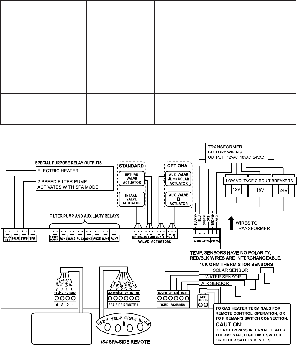
62
EasyTouch Wireless Control Panel Installation and User’s Guide
motpmySesuaCelbissoPnoituloS
fforononrutotsmeestinU
/resuehttuohtiwstiucric
rettimsnart
siemohybraenA
ralimisagnitarepo
tinusseleriw
dnarettimsnartehtrofedocsserddaetanretlanatceleS
dnareviecerhtobnosehctiwsehtegnahC.reviecer
.gnittesgnihctamtub,etanretlanaotetomer
tnempiuqesnrutylbadnepedtinU
sitnempiuqeecnotub,NO
ylbadnepedtonseodtigninnur
siegnarro,FFOtnempiuqenrut
tnempiuqenehwdecuderyltaerg
gninnursi
siesionlacirtceleeudnU
roenoybdecudorpgnieb
tnempiuqefoseceiperom
ehtotytimixorpesolcni
.reviecer
sahcustnempiuqemorfyawarevieceRehtetacoleR
tahtnoitacolanireviecerehtetacoleR.srotomrewolb
resuehtaeraehtotsnoitcurtsborewefsedivorp
.rettimsnartehtsetarepoylnommoc
yltaergsahtub,setarepotinU
roirpotderapmocegnardecuder
noitcnuf
siyrettaBrettimsnarT
.gniliaf
.)V32302epyt(yrettabrettimsnarTecalpeR
Problem: The Quick Touch remote will not work, or will not work dependably (Continued).
Indoor Control Panel
RF Transceiver
iS4 and iS10 Spa Side Remote
IntelliChlor
SOLAR BOOSTER PUMP/AUX EXTRA
QuickTouch
IntelliFlo VF, IntelliFlo VS
EasyTouch Outdoor Control Panel
(System Wiring Diagram)
63
EasyTouch Wireless Control Panel Installation and User’s Guide
First Time System Start-Up
The following information describes a basic system start-up procedure. Before you power up the EasyTouch
system at the Load Center first check the following:
Check Electronics
Check that the following plugs are seated correctly on the EasyTouch Load Center motherboard. For
connector locations, refer to the EasyTouch System Wiring Diagram on page 58.
• Relay connectors - FLTR PUMP - AUX 1 - 7 (EasyTouch 8), AUX 1 - 3 (EasyTouch 4)
• Temperature sensors connectors - WATER, SOLAR, AIR
• Transformer wire harness - J1
• Heater control connector - ELEC HTR and GAS HEATER (J19)
System Test
Follow the steps below to test the EasyTouch control panel to activate the heater, valves and pumps. This test
assumes that all system equipment has been properly installed and connected to the EasyTouch Load center.
Testing Valve Actuators and Pumps:
Use the following steps to test the valve actuators (CVA24T) for proper rotation.
To test the valve actuators and pump:
1. Switch on the electrical power at the house breaker.
2. Switch on the EasyTouch Load Center. You may need to switch on the breakers on the Load Center.
3. Press the Mode button to enable “Service” mode.
4. Press the Valve (V) button to select “Pool” mode.
5. Press the Filter Pump (F) button to activate the filter pump. Water will be removed from the pool
and returned to the pool. A spa bypass line divert a small amount of water to the spa. Make sure the
filter pump turns on correctly. If the pump has two speeds: Press the button one time to run the pump
in low speed. Press the button again to run the pump in high speed. Press the button again to switch
the pump off. A Two-Speed pump has to be configured in the 2-Speed menu (see page 44).
6. Set both valve actuators (CVA-24T) for suction and return. Use the toggle switch on the rear of the
CVA-24T to withdraw and return water from the pool.
7. Press the Valves (V) button. Step through all four valve positions: Pool, Spa, Fill, Drain. Make sure
the valves turn on correctly and the water is moving in the correct direction for each position. If
necessary, flip the actuator toggle switch to change the direction of the water.
Note: With the filter pump operating, if water is not being removed and returned to the pool,
it may be necessary to reverse the RETURN with VLV A (or VLV B) plugs on the EasyTouch
motherboard.
Testing the Auxiliary Relays
Affix the auxiliary relay labels to the appropriate buttons on the EasyTouch control panel and/or the
EasyTouch Indoor Control Panel. If necessary, write the function on the control panel.
1. Step through the rest of the auxiliary buttons. Notice which button turns on which equipment. You
may need to walk the property to find what each button turns on.
2. Write down what each button switches on, including the number of the circuit. You need this
information when you set up the Indoor Control Panel.
3. Label the circuit buttons on the outdoor control panel and the EasyTouch Indoor Control Panel.

64
EasyTouch Wireless Control Panel Installation and User’s Guide
Wiring UltraTemp Heat Pump to EasyTouch System
Be sure to check the UltraTemp terminal block wire colors and pinouts (located on the back of the Auto Set
board) before connecting it to the EasyTouch COM port on the motherboard. The See the wiring table below
for the pin configuration. For UltraTemp setup information, see page 38.
IMPORTANT: On the UltraTemp AutoSet board ONLY CONNECT PIN 3 (YELLOW) and PIN 2 (GREEN) to the
EasyTouch COM port pins YELLOW and GREEN respectively. Do not use pin 1 or pin 4 on the AutoSet board
or the EasyTouch motherboard. These pins are not used.
Wiring Description
eriwtropMOChcuoTysaE
roloc
noipircseDdnarebmunnipolFlamrehT
roloceriw
)DER(4NIP DESUTON CDV51+ DESUTON)DER(4NIP
)WOLLEY(3NIPATAD+)WOLLEY(3NIP
)NEERG(2NIPATAD-)NEERG(2NIP
)KCALB(1NIP DESUTON DNUORG DESUTON)KCALB(1NIP

65
EasyTouch Wireless Control Panel Installation and User’s Guide
Section 4
EasyTouch Transceiver Installation
Installing the EasyTouch Transceiver
The following procedure describes how to install the EasyTouch transceiver module and connect the
transceiver cable to the COM port on the EasyTouch motherboard. Read through the installation procedure
before starting.
EasyTouch wireless control panel kit
The EasyTouch wireless control panel kit consists of:
• EasyTouch wireless control panel
• Four AA-size alkaline batteries
• Transceiver module
• Four plastic anchors and retaining screws (to mount the transceiver module)
Mounting the EasyTouch Transceiver
The Transceiver is a two-way radio device with an attached antenna that communicates to and from the
EasyTouch system via the wireless hand-held wireless control panel. Mount the Transceiver module at a
convenience location (on a flat vertical surface) near the Load Center, at a minimum of 5 ft. above ground
level to optimize the functional operating range of the wireless control panel.
CAUTION - To avoid signal interference, mount the Transceiver antenna a minimum of
10 ft. away from the Load Center, any metal surface/structure, or air blower located in the immediate area of
the equipment pad.
To mount the EasyTouch transceiver near the EasyTouch load center:
1. CAUTION - Switch the main power off at the EasyTouch load center.
2. Remove the two retaining screws securing the transceiver case to the back plate. Carefully slide the
case off the back plate.
3. CAUTION - Electrostatic Discharge (ESD): Hold the circuit board from the edges. Do not
touch the board components, electrostatic discharge can damage the board. Slide the
transceiver circuit board up and out of the back plate.
4. Position the back plate against the mounting surface so that the case is oriented in an upright position
(with the antenna pointing upwards). Use a pencil to mark the four mounting points. Drill four 3/16 in.
diameter holes into the mounting surface. If screws are not being used, insert the four plastic wall
anchors (provided in the kit).
5. Feed the provided 10 ft. of UL approved four 22 AWG conductor cable through the knockout hole at
the bottom of the enclosure. Do not run wire through the drain holes. If the knockout hole is not being
used to run wire through, drill a hole through the bottom of the back plate, route the wire through the
hole and seal it using a fitting with a few feet of conduit or some other sealant between the case and
the cable.
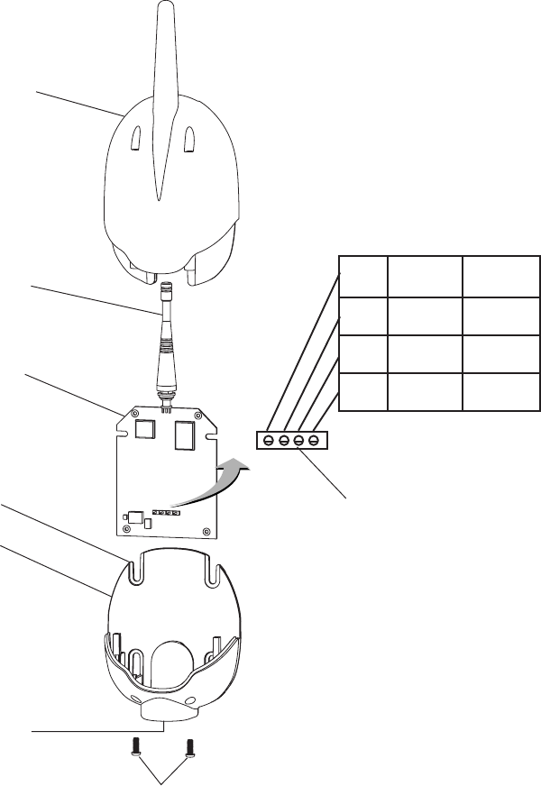
66
EasyTouch Wireless Control Panel Installation and User’s Guide
6. Position the back plate over the mounting points and secure it with the four mounting screws
(provided in the kit).
7. Carefully slide the transceiver circuit board into the back plate.
8. Strip the leads of the communication cable wires back ¼ in. Insert the wires into the connector screw
terminals (provided in the kit). Using a small flat-blade screwdriver, secure the wires with the
terminal screws. Make sure to match the color-coding of the wires: GND = Black, Green = -DT,
Yellow = +DT, and Red = +15. Connect the screw terminal connector onto the transceiver circuit
board.
9. Slide the case over the back plate. Secure the case to the back plate using the two retaining screws.
10. Proceed with “Connecting the Transceiver to the EasyTouch Load Center,” on page 67.
Transceiver Module
Screw terminals
Back plate
Retaining screws
Transceiver circuit board
Case
Knockout hole
Antenna
Mounting point (4x)
1DNGKLB
2TD-NRG
3TD+LEY
4V51DER
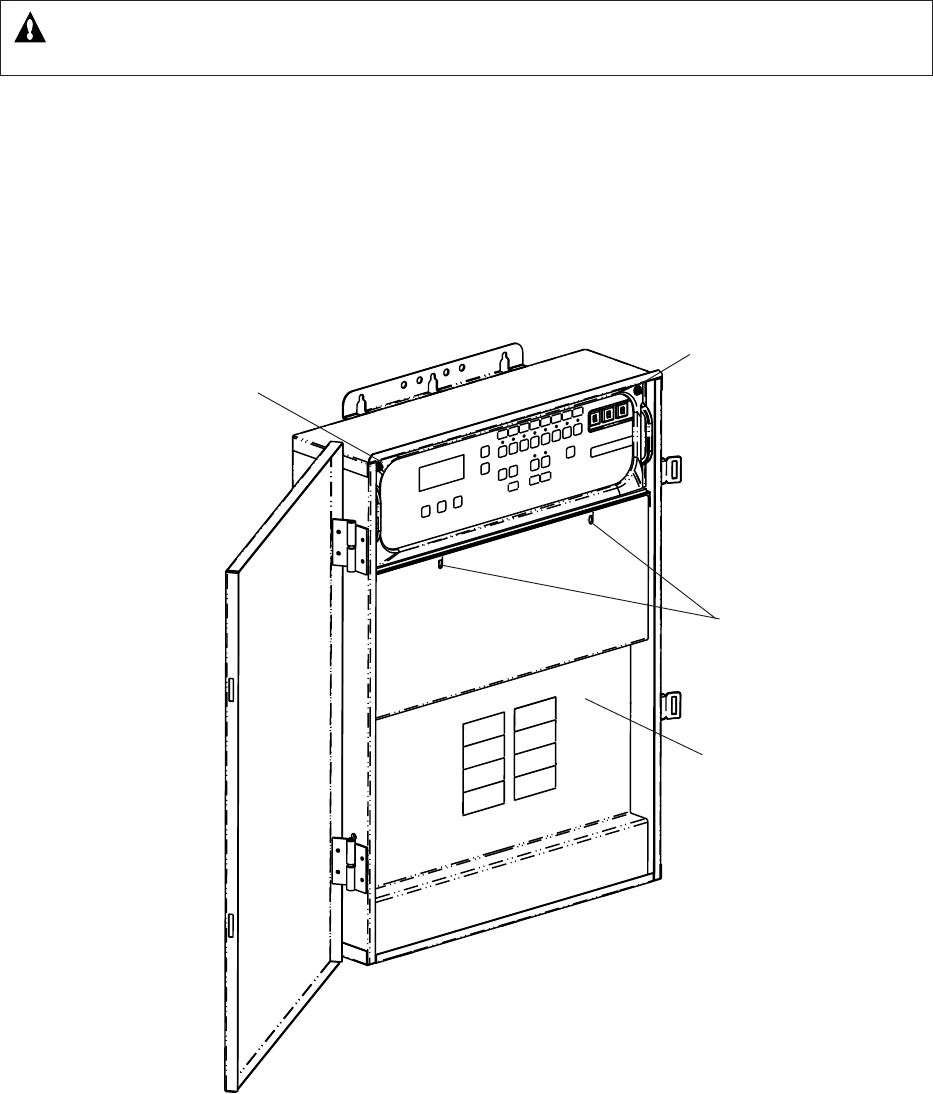
67
EasyTouch Wireless Control Panel Installation and User’s Guide
Connecting the Transceiver to the EasyTouch Load Center
WARNING - Switch OFF the main system power to the EasyTouch load center before making any
connections.
1. Unlatch the two enclosure door spring latches, and open the door.
2. Remove the two retaining screws securing the high voltage cover panel, and remove it from the
enclosure.
3. Loosen the two access screws securing the control panel.
EasyTouch Load Center (front view)
High voltage
cover panel
Retaining screw
Control panel
access screw
Control panel
access screw
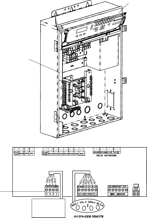
68
EasyTouch Wireless Control Panel Installation and User’s Guide
4. Lower down the hinged control panel to access the EasyTouch motherboard.
5. Route the four conductor transceiver connection cable into the lower plastic grommet, up through the
low voltage raceway to the EasyTouch load center motherboard.
6. Strip back the cable conductors ¼ inch. Insert the wires into the screw terminals (provided in the kit).
Secure the wires with the screws. Make sure to match the color-coding of the wires:
GND = Black, Green = -DT, Yellow = +DT, and Red = +15
7. Insert the screw terminal connector onto the COM-PORT (J20) connector on the motherboard.
Note: Multiple wires may be inserted into a single screw terminal.
8. Close the control panel into its original position and secure it with the two access screws.
9. Install the high voltage cover panel and secure it with the two retaining screws.
10. Close the EasyTouch load center front door. Fasten the two spring latches.
11. Switch the power on to the EasyTouch load center.
Low voltage
Raceway
Control panel
motherboard
COM PORT
(J20)
Indoor Control Panel
IntelliChlor
IntelliFlo
RF Transceiver
EasyTouch Motherboard
69
EasyTouch Wireless Control Panel Installation and User’s Guide
Glossary
Aux Extra: An additional auxiliary output circuit that uses the Solar socket (J17) on the EasyTouch
motherboard. Uses the Down arrow button on the wireless control panel to switch circuit on and off. Only
available if solar equipment is not being used.
COM port: RS-485 communication port for connection to iS10 spa-side remote controller, UltraTemp heat
pump, EasyTouch Indoor Control Panel, IntelliChlor, IntelliFlo and QuickTouch RF transceiver. A four pin
terminal block located on the EasyTouch motherboard.
High Voltage Compartment: Large lower right compartment of Load Center for all high voltage wiring
including circuit breakers, relays, and GFCI.
Wireless Control Panel: Nine or 14 button remote controller with LCD (liquid crystal display) wired to the
EasyTouch motherboard in the load center.
iS4: Four function Spa-Side remote. Can be spa wall or deck mounted.
Load Center: Metal enclosure with power relays, transformer, and circuit breakers. Used for distributing
power for controlling the EasyTouch system. Also known as the “sub-panel.”
Low Voltage Compartment: Top compartment of Load Center for all low voltage wiring.
Low Voltage Raceway: Vertical space in the left side of EasyTouch load center for low voltage cabling.
Motherboard: The circuit board mounted on top of the EasyTouch control panel. The EasyTouch
motherboard defines the system capabilities.
Outdoor Control Panel: EasyTouch control panel with flexible hinge installed in upper portion of EasyTouch
Load Center to control the EasyTouch system.
Receiver/Antenna: Used with the QuickTouch (QT4) to receive radio frequency (wireless) transmissions.
RF Transceiver: Used with the EasyTouch wireless control panel to transmit and receive radio frequency
(wireless) transmissions.
Relay Circuits: The circuits that control the relay outputs on the EasyTouch motherboard. Connectors are
located on the top edge of the circuit board.
Screw Terminal Connector: Removable connector that may attach to circuit board with multiple sockets
(anywhere from 2 to 12) to receive wires from controllers and sensors; wires held by screw terminals; multiple
wires of a small enough gauge (usually 22 AWG) may be coupled to a single socket of a terminal connector.
Sockets are located on the EasyTouch motherboard.
Blank Page
Blank Page

P/N 520688 - Rev F
*520688*