Pentair Aquatic Systems ICHNDHLD IntelliCenter Wireless Remote Control User Manual 041217
Pentair Aquatic Systems IntelliCenter Wireless Remote Control Users Manual 041217
Users Manual 041217
IMPORTANT SAFETY INSTRUCTIONS
READ AND FOLLOW ALL INSTRUCTIONS
SAVE THESE INSTRUCTIONS
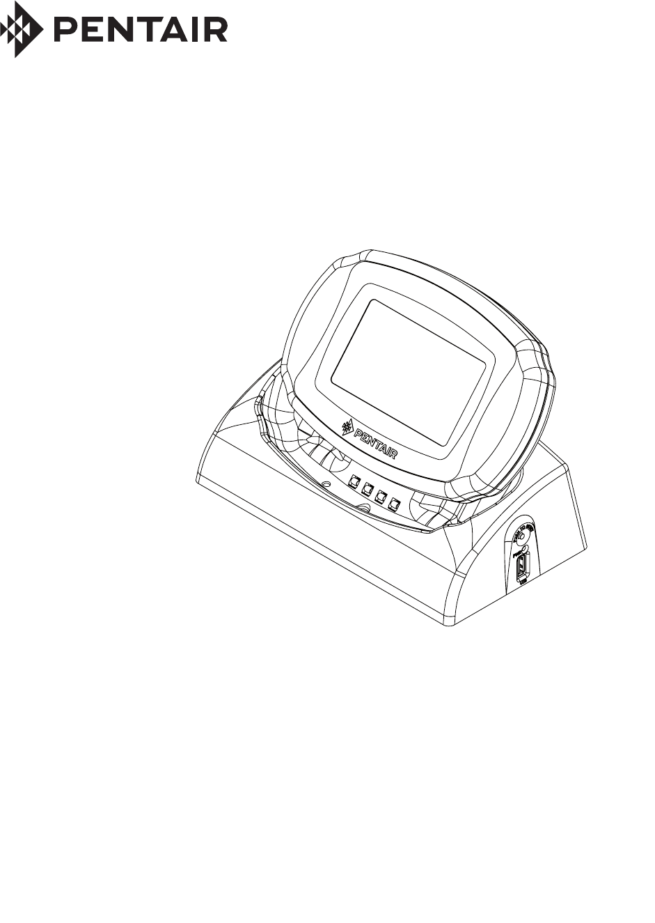
INTELLICENTER™ WIRELESS CONTROL SYSTEM
WIRELESS CONTROL PANEL
INSTALLATION GUIDE
Contents
P/N 523213 Rev A 2/2017
Warning and Safety Instructions iii-vi
IntelliCenter Control System Wireless Control Panel 1
Charging the IntelliCenter Wireless Control Panel 2
Home Screen Battery Icon 3
Wireless Control Panel Transceiver Installation 4
IntelliCenter Control System Wireless Controller kit 4
Mounting the Wireless Transceiver 4
Connecting the Transceiver to the IntelliCenter
Control System Load Center 6
Home Screen 6
Transceiver Connected to the IntelliCenter
Control System Load Center 8
IntelliCenter Control System Setup 9
Power On the Load Center 9
Setup the Wireless Control Panel 9
Wireless Control Panel Firmware Update 11
IntelliCenter Control System Menu Structure 12
iii
IntelliCenter Control System Wireless Control Panel Installation Guide
This product is designed and manufactured for safe and reliable service when installed, operated and
maintained according to the information and installation codes referred to in this Guide.
Risk of Electrical Shock or Electrocution!
- Always disconnect power at the circuit breaker before servicing the load center.
Improper installation can create an electrical shock hazard that can result in death
or serious injury.
This product must be installed by a licensed or certified electrician or a qualified
pool professional in accordance with the current National Electrical Code (NEC),
NFPA 70 or the Canadian Electrical Code (CEC), CSA C22.1. All applicable local
installation codes and ordinances must also be adhered to. Improper installation
will create an electrical hazard which could result in death or serious injury to pool
users, installers or others due to electrical shock, and may also cause damage to
property. Always disconnect the power to the pool light at the circuit breaker before servicing the light.
Failure to do so could result in death or serious injury to serviceman, pool users or others due to
electrical shock.
READ AND FOLLOW ALL WARNING AND SAFETY INSTRUCTIONS
SERIOUS BODILY INJURY OR DEATH CAN RESULT IF THIS PRODUCT (UNIT) IS NOT
INSTALLED AND USED CORRECTLY.
INSTALLERS, POOL OPERATORS AND POOL OWNERS MUST READ THESE
WARNINGS AND ALL INSTRUCTIONS BEFORE USING THIS PRODUCT. This Guide
provides installation and operation instructions for the product. Consult Pentair
Water Pool and Spa, Inc. (“Pentair”) with any questions regarding this
product.
This product is intended for use with swimming pool applications only.
Most states and local codes regulate the construction, installation, and operation of public pools and spas, and
the construction of residential pools and spas. It is important to comply with these codes, many of which directly
regulate the installation and use of this product. Consult your local building and health codes for more informa-
tion.
This guide provides installation and operation instructions for the IntellliCenter™ Control System Wireless Control
Panel. Consult Pentair Water Pool and Spa, Inc. with any questions regarding this equipment (see “Customer
Service/Technical Support”, page ii).
Attention Installer: This guide contains important information about the installation, operation and safe usage
of this product. Give this guide to the owner and/or operator of this equipment after installation.
Attention User: This manual contains important information that will help you in operating and maintaining this
filter. Please save it for future reference.
Attention User: This Guide contains important information that will help you in operating and maintaining this
product. Please retain it for future reference. Read the entire Installation Guide and all related warning labels
before installing this product. Read the operating instructions and warnings for all equipment in the pool circulat-
ing system before operating. Failure to follow safety warnings and instructions can result in severe injury, death,
or property damage. Call (800) 831-7133 for additional free copies of this Guide or replacement safety labels.
IMPORTANT WARNING AND SAFETY INSTRUCTIONS
This is a safety alert symbol. When you see this symbol in this manual or on the product, look for
one of the following signal words; DANGER, WARNING, CAUTION and NOTICE and comply with the
information. Be alert to the potential hazard. Ensure to read and comply with all of the warnings and
cautions in this manual.
iv
IntelliCenter Control System Wireless Control Panel Installation Guide
Water temperature in excess of 100° F (37.7° C) may be hazardous to your health.
Prolonged immersion in hot water may induce hyperthermia. Hyperthermia occurs
when the internal temperature of the body reaches a level several degrees above
normal body temperature of 98.6° F (37° C.). Effects of hyperthermia include:
(1) Unawareness of impending danger. (2) Failure to perceive heat. (3) Failure to
recognize the need to leave the spa. (4) Physical inability to exit the spa. (5) Fetal
damage in pregnant women. (6) Unconsciousness resulting in danger of drowning.
The use of alcohol, drugs, or medication can greatly increase the risk of fatal
hyperthermia in hot tubs and spas.
A pool or spa pump must be installed by a qualified pool and spa service professional
in accordance with the current National Electrical Code and all applicable local codes
and ordinances. Improper installation may create an electrical hazard which could
result in death or serious injury to pool users, installers, or others due to electrical
shock, and may also cause damage to property.
IMPORTANT WARNING AND SAFETY INSTRUCTIONS
The use of alcohol, drugs, or medication can greatly increase the risk of fatal hyperthermia
in hot tubs and spas. This product is intended to control heaters with built-in high limit
circuits ONLY. Failure to do so may cause property damage or personal injury.
For units intended for use in other than single-family dwellings, a clearly labeled
emergency switch shall be provided as part of the installation. The switch shall be readily
accessible to the occupants and shall be installed at least five (5) feet (1.52 m) away,
adjacent to, and within sight of, the unit.
Except for listed spa-side remote controls, install a minimum of five (5) feet (1.52 m) from
the inside wall of the pool and spa.
For information about the Virginia Graeme Baker Pool and Spa Safety Act, contact the Consumer Product Safety
Commission at (301) 504-7908 or visit www.cpsc.gov.
NOTE: Always turn off all power to the pool pump before installing the cover or working on any suction outlet.
Two Speed Pump Controls Notice (Title 20 Compliance)
Please read the following important Safety Instructions - When using two-speed pumps
manufactured on or after January 1, 2008, the pump’s default circulation speed MUST be set to the
LOWEST SPEED, with a high speed override capability being for a temporary period not to exceed one
normal cycle, or two hours, whichever is less.
CAUTION: IMPORTANT BATTERY INFORMATION
• Danger of explosion if battery is incorrectly replaced.
• ONLY USE a Pentair Water Pool and Spa (“Pentair”) replacement battery. Order Battery
(P/N 522054).
• Rechargeable Lithium-ion battery disposal: Unwanted lithium ion battery pack may be returned to
your local recycling center or the manufacturer for disposal.
• Dispose of used batteries according to the manufacturer’s instructions.

v
IntelliCenter Control System Wireless Control Panel Installation Guide
FCC Standard - 47 CFR Part 15, Subpart C (Section 15.247). This version is limited to chapter 1 to chapter 11 by
specified firmware controlled in the U.S.A.
FCC RF Exposure requirements:
Notice for Virtual Cable (FCC ID: P4H-ICVC & IC: 4249A-ICVC): In order to comply with FCC/IC RF Exposure requirements,
a minimum separation distance of 8 in (20 cm) must be maintained between the equipment and all persons during normal
operation.
Afin de satisfaire aux exigences de la FCC/IC l’exposition RF, une distance de séparation minimale de 8 po (20 cm) doit être
maintenue entre l’équipement et toutes les personnes en fonctionnement normal.
Notice for Wireless Remote Control (FCC ID: P4H-ICHNDHLD & IC: 4249A-ICHNDHLD):
This portable transmitter with its antenna has shown compliance with FCC/IC SAR limits for general population / uncontrolled
exposure. The maximum listed SAR level is 0.88 W/kg (body). The antenna used for this device must not be co-located or
operating in conjunction with any other antenna or transmitter.
Cet émetteur portable avec son antenne a démontré la conformité aux limites de la FCC/IC SAR pour la population générale /
exposition non contrôlée. Le niveau maximal de SAR cotée est 0.88 W/kg (corps). L’antenne utilisée pour cet appareil ne doit
pas être co-implanté ou fonctionner en conjonction avec toute autre antenne ou émetteur.
Canada - Industry Canada (IC) - The IntelliCenter™ Control System and Wireless Control Panel complies with RSS210 of
Industry Canada. (1999). Operation is subject to the following two conditions: (1) this device may not cause interference,
and (2) this device must accept any interference, including interference that may cause undesired operation of the device.
The device complies with industry Canada’s License Exempt RSSs. Operation is subject to the following: (1) This device
may not cause interference; and (2) This device must accept interference that may cause undesired operation of the
device.
Le dispositif est conforme à la licence d’Industrie Canada Exempt CNR. Le fonctionnement est soumis à la suivante.
(1) Ce ne doit pas provoquer d’interférences ; et (2) Cet appareil doit accepter les interférences qui peuvent causer un
mauvais fonctionnement de l’appareil.
This Class B digital apparatus complies with Canadian ICES-003.Cet appareil numérique de la classe B est conforme à
la norme NMB-003 du Canada. The term “IC” before the certification / registration number only signifies that the Industry
Canada technical specifications were met.
Instruction to User - The IntelliCenter Control System and the Wireless Control Panel has been tested and found to
comply with the limits for a Class B digital device, pursuant to Part 15 of the FCC Rules. These limits are designed
to provide reasonable protection against harmful interference in a residential installation. The IntelliCenter Control
System and Wireless Control Panel generates, uses and can radiate radio frequency energy and, if not installed and
used in accordance with the instructions, may cause harmful interference to radio communications. However, there is
no guarantee that interference will not occur in a particular installation. If this device does cause harmful interference to
radio or television reception, which can be determined by switching the device off and on, the user is encouraged to try to
correct the interference by one or more of the following measures:
•Reorient or relocate the receiving antenna.
• Increase the separation between the equipment and receiver.
•Connect the equipment into an outlet on a circuit different from that to which the receiver is connected.
•Consult the dealer or an experienced radio/TV technician for help.
IMPORTANT WARNING AND SAFETY INSTRUCTIONS
FCC non-modification statement:
Changes or modifications not expressly approved by the party responsible for compliance could void the user’s authority to
operate the equipment.

vi
IntelliCenter Control System Wireless Control Panel Installation Guide
CUSTOMER SERVICE / TECHNICAL SUPPORT
Customer Service
8 A.M. to 7.30 P M — Eastern and Pacific Times
Phone: (800) 831-7133
Fax: (800) 284-4151
Visit www.pentairpool.com
Technical Support
Sanford, North Carolina (8 A.M. to 7.30 P M ET)
Phone: (919) 566-8000
Fax: (919) 566-8920
Moorpark, California (8 A.M. to 4.30 P.M. PT)
Phone: (805) 553-5000 (Ext. 5591)
Fax: (805) 553-5515
General Installation Information
1. All work must be performed by a licensed electrician, and must conform to all national, state, and
local codes.
2. Install to provide drainage of compartment for electrical components.
3. If this system is used to control underwater lighting fixtures, a ground-fault interrupter (GFCI) must
be provided for these fixtures. Conductors on the load side of the ground-fault circuit-interrupter
shall not occupy conduit, junction boxes or enclosures containing other conductors unless such
conductors are also protected by a ground-fault circuit-interrupter. Refer to local codes for details.
4. A terminal bar stamped is located inside the supply terminal box. To reduce the risk of electric
shock, this terminal must be connected to the grounding means provided in the electric supply
service panel with a continuous copper wire equivalent in size to the circuit conductors supplying
this equipment (no smaller than 12 AWG or 3.3 mm). The bonding lug(s) provided on this unit
are intended to connect a minimum of one No. 8 AWG for US installation and two No. 6 AWG for
Canadian installations solid copper conductor between this unit and any metal equipment, metal
enclosures or electrical equipment, metal water pipe, or conduit within 5 feet (1.5 m) of the unit.
5. The electrical supply for this product must include a suitably rated switch or circuit breaker to open
all ungrounded supply conductors to comply with in accordance with the current National Electrical
Code (NEC), NFPA 70 or the Canadian Electrical Code (CEC), CSA C22.1. All applicable local
installation codes and ordinances must also be adhered to. The disconnecting means must be
readily accessible to the tub occupant but installed at least 10 ft. (3.05 m) from the inside wall of
the pool.
6. GAS HEATER: This automation control system is designed to supply high voltage (120 VAC / 240
VAC) to a gas heater and override the thermostat in the heater’s control circuit. This automation
control system is intended to control gas heaters with a high temperature limit switch(s) safety
circuit.
IMPORTANT WARNING AND SAFETY INSTRUCTIONS
IntelliCenter Control System Wireless Control Panel Installation Guide IntellliCenter Control System Wireless Control Panel Installation Guide
1
IntelliCenter™ Control System Wireless Control Panel
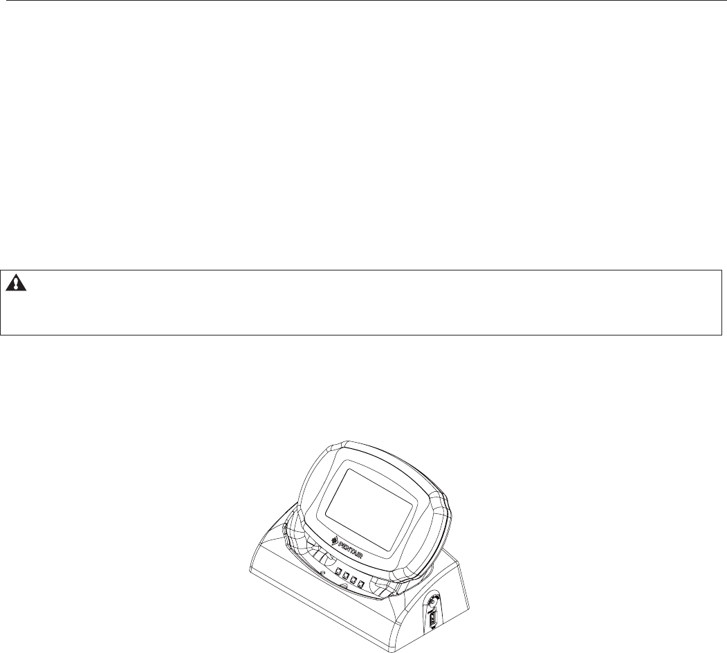
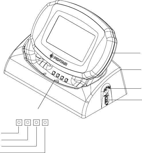
IntelliCetner Control System Wireless Control Panel in Cradle
IntelliCenter Wireless Control Panel kit (P/N 520036) contents
• Wireless Control Panel
• AC/DC power adapter
• Cradle
• User’s and Installation Guide (this manual)
This guide contains all of the information you need to setup and operate the InitelliCenter Control
System Wireless Control Panel.
IntelliCenter Wireless Control Panel provides the same functionality as the IntelliCenter Control System
Indoor and outdoor Control Panel. The operating range of the wireless control panel is approximately
300 ft. from the wireless transceiver antenna (line of sight) which is typically located near the
IntelliCenter load center. The optimum wireless transmit and receive range may be affected by physical
obstructions, (especially those containing metal), weather conditions, and geographical features.
The wireless control panel LCD screen can be sensitive to sunlight. When exposed for extended peri-
ods the LCD screen will heat up and go black. If this happens, place the remote in a shaded area and
allow the screen to cool down. Do not attempt to adjust the contrast or the screen will be unreadable
when it eventually cools. When used outside, keep the remote covered or in a shaded area. Prolonged
exposure to sunlight may permanently damage the unit.
WARNING! Do not plug in the AC adapter to a power source within five (5) eet of the pool
and spa. Canadian installations require a minimum of (3) meters from pool water. Do not
recharge outdoors. Only use Pentair approved AC power adapter transformer.
The IntelliCenter Wireless Control Panel is water resistant and can be exposed to temporary splashing
or wet hands. However, the controller is not intended to be submersed. Remove unit immediately if it is
dropped in the water or exposed to rain. Store the unit indoors in a dry environment. Be sure the gold
charging contacts are dry before charging
2
IntelliCenter Control System Wireless Control Panel Installation Guide IntellliCenter Control System Wireless Control Panel Installation Guide
Charging the IntelliCenter Wireless Control Panel
When you are not using the IntelliCenter Wireless Control Panel, place it in the cradle to recharge the
battery. This allows the battery to be fully charged at all times.
To charge the Wireless Control Panel battery
• Plug the AC adapter into an AC wall outlet.
• Insert the AC Power Adapter plug into the bottom of the cradle.
• Place the Wireless Control Panel in the cradle.
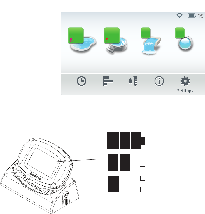
• Look for the battery charging indicator on the front of the cradle (see below).
Note: When the Wireless Control Panel is placed in the cradle the display and backlight will be
on. After five minutes the backlight will shut off. The Wireless Control Panel unit and display are
always on when seated in the cradle. To turn the backlight on, tap on the screen.
To use the Wireless Control Panel
1. Remove the Wireless Control Panel from the cradle. Note: With AC power connected to
the cradle, the Wireless Control Panel can be used while seated in the cradle.
2. Tap the Wireless Control Panel touchscreen to turn the unit on. The main screen is
displayed. The LCD backlight will turn off in two minutes if not in use. The battery icon
displays three solid bars, only when it’s fully charged. Note: The device can be used all
day at full power with a complete battery charge (3 to 4 hours). If the Wireless Control
Panel is not being used for extended periods of time disconnect the AC power Adapter
from the power source.
Reset Button
USB Plug.
Use USB flash drive to
update the IntelliCenter
Control System Wireless
Control Panel firmware. See
page 16.
Cradle
(AC Power Plug on back of
cradle (not shown)
Wireless Control Panel
Cradle indicators
Ground Pin
USB Data+
+5 V Pin
USB Data-
IntelliCenter Control System Wireless Control Panel Installation Guide IntellliCenter Control System Wireless Control Panel Installation Guide
3
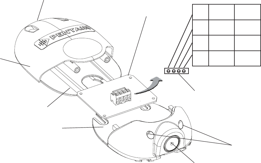
Home Screen Battery Icon
The Wireless Control Panel battery icon is located in the upper right corner of the Home screen. If the
battery icon displays one or no bars or the screen is blank, this may indicate that the battery
cannot power the device and needs recharging.
A complete battery charge takes about 3 to 4 hours. During battery recharge, the battery icon bars
scroll from left to right. When the battery is fully charged the left to right scrolling of the battery icon will
stop. The battery icon will be solid when the battery is fully charged.
Note: If the battery requires replacement, only use Pentair replacement battery (P/N 522054).
Sufficient charge left in the
batteries to operate device.
Three solid bars indicate ample battery
charge. During battery recharge, bars scroll
left to right.
Batteries will deplete soon.
Battery Icon
Pool Spa Features Lights
Air Temp 65° F
Schedule Usage Chemistry Status
3 3
84°
78°
92°
85°
8:00 A.M.
Battery Icon
IntelliCenter Control System Home Screen

4
IntelliCenter Control System Wireless Control Panel Installation Guide IntellliCenter Control System Wireless Control Panel Installation Guide
Wireless Control Panel Transceiver Installation
The following procedure describes how to install the IntelliCenter Control System Wireless
Controller transceiver module and connect the Transceiver cable to the COM port on the
IntelliCenter Control System main circuit board.
Note: IF YOU ARE USING MULTIPLE WIRELESS CONTROLLER: IntelliCenter Control System
Wireless Controller, be sure the Transceiver for each of these controllers are located at least 6 ft.
apart for each other. This will avoid digital interference and ensure better wireless reception.
IntelliCenter Control System Wireless Controller kit
The Wireless Control Panel kit consists of:
• Wireless Control Panel
• Wireless Transceiver
• Transceiver module Installation Instructions (P/N 522056)
• Four plastic anchors and retaining screws (to mount the transceiver module)
Mounting the Transceiver
The Transceiver is connected to the IntelliCenter Control System via the RS-485 bus. The
Transceiver is connected to the Wireless Control Panel via a 2.4GHz RF connection. Mount the
Transceiver module at a convenient location (on a flat vertical surface) near the Load Center, at
a minimum of 5 ft. above ground level to optimize the functional operating range of the wireless
control panel.
Note: To avoid signal interference, mount the Transceiver antenna a minimum of
10 ft. away from the Load Center or Power Center, any metal surface/structure, or air blower located
in the immediate area of the equipment pad.
To mount the transceiver near the IntelliCenter Control System Load Center:
1. Switch OFF the main power off to the IntelliCenter Control System Load Center.
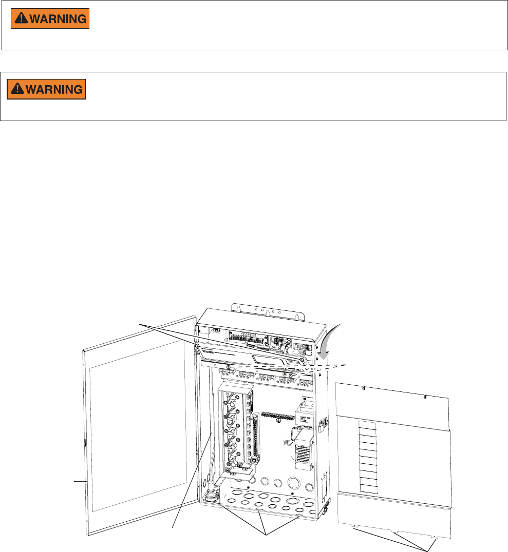
2. Remove the two retaining screws securing the transceiver case to the back plate. Carefully
slide the case off the back plate.
3. CAUTION - Electrostatic Discharge (ESD): Hold the circuit board from the edges.
Do not touch the board components, electrostatic discharge can damage the board.
Slide the transceiver circuit board up and out of the back plate.
4. Position the back plate against the mounting surface so that the case is oriented in
an upright position (with the antenna pointing upwards). Use a pencil to mark the four
mounting points. Drill four 3/16 in. diameter holes into the mounting surface. If screws are
not being used, insert the four plastic wall anchors (provided in the kit).
5. Feed the provided 10 ft. of UL approved four 22 AWG conductor cable through the
knockout hole at the bottom of the enclosure. Do not run wire through the load center drain
holes. If the knockout hole is not being used to run wire through, drill a hole through the
bottom of the back plate, route the wire through the hole and seal it using a fitting with a
few feet of conduit or some other sealant between the case and the cable.
IntelliCenter Control System Wireless Control Panel Installation Guide IntellliCenter Control System Wireless Control Panel Installation Guide
5
6. Position the back plate over the mounting points and secure it with the four mounting screws
(provided in the kit).
7. Carefully slide the transceiver circuit board into the back plate.
8. Strip the leads of the communication cable wires back ¼ in. Insert the wires into the connector
screw terminals (provided in the kit). Using a small flat-blade screwdriver, secure the wires with
the terminal screws. Make sure to match the color-coding of the wires: GND = Black, Green = -DT,
Yellow = +DT, and Red = +15. Connect the screw terminal connector onto the transceiver circuit
board.
9. Slide the case over the back plate. Secure the case to the back plate using the two retaining screws.
10. Proceed to “Connecting the Transceiver to the IntelliCenter Control System Load Center,” on
the next page.
Transceiver Module
Back plate
Retaining screws
Transceiver
circuit board
Case
Knockout hole
Antenna
Mounting point (4x)
Screw terminals
1 GND BLK
2 - DT GRN
3 + DT YEL
4 15V RED
Mounting the Transceiver (Continued)
6
IntelliCenter Control System Wireless Control Panel Installation Guide IntellliCenter Control System Wireless Control Panel Installation Guide
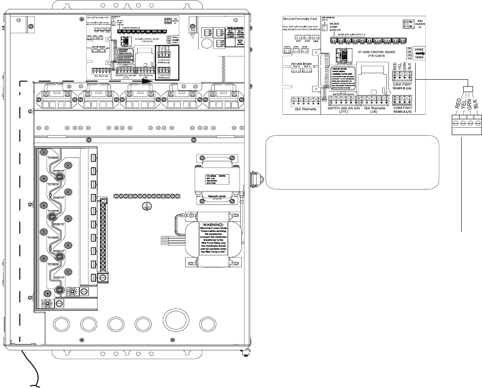
Connecting the Transceiver to the IntelliCenter™ Control System Load Center
SWITCH OFF AC POWER TO THE INTELLICENTER CONTROL SYSTEM LOAD
CENTER BEFORE MAKING ANY CONNECTIONS.
IntelliCenter™ Load Center Control System Load Center (front view)
(High Voltage Cover Panel removed)
To connect the Transceiver wires to the COM port on the system circuit board:
BEFORE REMOVING THE HIGH VOLTAGE COVER PANEL FROM THE
LOAD CENTER OR POWER CENTER ENCLOSURE SWITCH OFF THE POWER
AT THE HOUSE MAIN CIRCUIT BREAKER BOX.
1. Switch OFF AC power to the enclosure at the main house panel circuit breaker.
2. Unlatch the front door latch and open the front door. Remove the two retaining screws from the High
Voltage Cover Panel and remove the panel.
3. Loosen the two retaining screws securing from the top edge of the Outdoor Control Panel. Fold
down the Outdoor Control Panel to access the circuit board sockets connectors for the electrical
connections. Remove the panel from the enclosure (see illustration below).
4. Route the four conductor transceiver connection cable into the lower plastic grommet, up through
the low voltage raceway to the system circuit board.
LOW VOLTAGE
RACEWAY High Voltage Cover Panel Tabs (3)
Remove two (2) retaining
screws securing High Voltage
Cover Panel
Front door
High Voltage Cover Panel slots (3)
Flip down the Outdoor Control Panel
to access circuit board and low
voltage compartment
Loosen Outdoor Control
Panel retaining screws
IntellliCenter Control System Wireless Control Panel Installation Guide
7
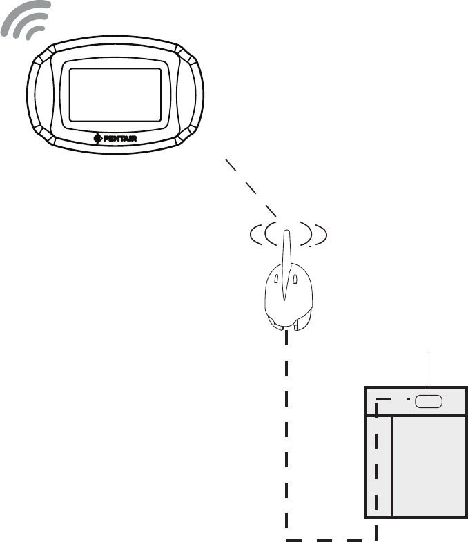
5. Strip the leads of the communication cable wires back ¼ in. Insert the wires into the connector
screw terminals (provided in the kit). Using a small flat-blade screwdriver, secure the wires with
the COM PORT terminal screws. Make sure to match the color-coding of the wires: GND = Black,
Green = -DT, Yellow = +DT, and Red = +15. Connect the screw terminal connector onto the
transceiver circuit board.
Connecting the Transceiver to the IntelliCenter™ Control System Load Center (Continued)
6. Reinstall the High Voltage Panel: Insert the panel’s three tabs into the lower slots on the enclosure.
Secure the panel with the two (2) retaining screws. Close the front door and secure with the latch.
7. After the IntelliCenter™ Control System Load Center is powered up the Wireless Control Panel will
automatically synchronize with the system and will be ready for operation.
8. Close the Load Center front door. Fasten the spring latch.
9. SWITCH ON AC POWER to the Load Center.
IntellliCenter Control System Wireless Control Panel Installation Guide
COMMUNICATION PORTS A & B
14 VDC, 2.0A Max. Combined.
IntelliCenter™ Control System COM PORT:
Strip 1/4” insulation from the green and yellow wire conductors.
• Connect the Green wire to pin 2 on Connector J4 or J5.
• Connect the Yellow wire to pin 3 on Connector J4 or J5.
Note: Multiple wires may be inserted into a single terminal.
Optional: COM PORT expansion module (P/N 520818) with 3 extra
COM PORTS up to 2 modules can be installed.
COM Port A (J5)
and COM Port B (J4)
14 VDC, 2.0A Max.
Combined
4 3 2 1
+15 +DT -DT GND
i5PS IntelliCenter Control System Main Circuit Board
(with optional Expansion Board shown)
COM Port
(J4)
COM Port
(J5)
IntelliCenter Control System Main Board
Connect
Transceiver cable to
RS_485 COM port (J4 or J5)
8
IntelliCenter Control System Wireless Control Panel Installation Guide IntellliCenter Control System Wireless Control Panel Installation Guide
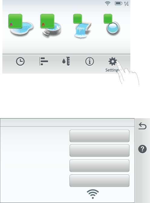
IntelliCenter
Control System
Load Center
(Located outside at
equipment pad)
Transceiver connects to the
IntelliCenter Control System
RS-485 (COM Port) on the
main circuit board
Wireless Control Panel
RS-485 (COM Port)
Transceiver
Transceiver Connected to the IntelliCenter™ Control System Load Center
IntelliCenter Control System Wireless Control Panel Installation Guide IntellliCenter Control System Wireless Control Panel Installation Guide
9
IntelliCenter Control System Wireless Control Panel Setup
The IntelliCenter Control System Wireless Control Panel requires optional Kit P/N 522036. This
kit includes a wireless transceiver with antenna which connects to an RS-485 COM port on the
Outdoor Control Panel circuit board located in the control system Load Center. For IntelliCenter
Control System start up information, refer to the IntelliCenter™ Control System User’s Guide
(P/N 522561). Note: IntelliCenter Control System settings made on the outdoor, indoor or wireless
control panel control panel are synchronized to have the same system settings on each control
panel.
Power On the Load Center
1. After all the necessary pool and spa equipment has been connected to the Load Center, replace
and secure the High Voltage Panel onto the front of the Load Center.
2. Switch on the main circuit breakers to apply power to the Load Center.
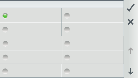
Setup the Wireless Control Panel
1. From the Home screen on the Wireless Control Panel. Tap Settings > Advanced System
Configuration > Intellicenter Wireless Remote Setup to access the IntelliCenter Wireless
Remote Setup Screen.
Pool Spa Features Lights
Air Temp 65° F
Schedule Usage Chemistry Status
3 3
84°
78°
92°
85°
8:00 A.M.
0.00
FW Version
Device
Name
IntelliCenter Wireless Remote Setup
Signal Strength
-90dB, 255
RSSI and LQI
12
Channel
3. Choose the best Channel for Signal Strength: From the IntelliCenter Wireless Remote Setup
Screen you can name the wireless control panel, view the current firmware, view the current RSSI
and LQI values and choose a channel withe the best signal strength.
Name: Tap the Name button, and enter a
name for the wireless remote.
FW Version: Tap the FW Version button to
view the firmware version of the wireless
remote.
RSSI and LQI: Tap this button to view:
RSSI: A higher RSSI value indicates higher
power. Received Signal Strength (Power) In-
dication (in dBm) (RSSI). See Signal Strength
connectivity description below.
LQI: The Link Quality Indicator value is from
0 to 255 from the wireless remote transceiver
(TXR). This value is best used as a relative
measurement of the link quality. (a high LQI
value indicates a better link than a low LQI
value does).
10
IntelliCenter Control System Wireless Control Panel Installation Guide IntellliCenter Control System Wireless Control Panel Installation Guide
Select Wireless Channel
12 13
14 15
16 17
18 19
20 21
Signal Strength: Displays the wireless signal strength to and from the IntelliCenter Control Sys-
tem wireless antenna.
• -9 = 100% connectivity: All signal strength bars indicate optimum wireless
performance.
• -90 = 0% connectivity: No connection to wireless transceiver antenna.
Note: The wireless control panel signal strength and battery icon are displayed on the Home
screen. See page 4.
Channel: Tap the Wireless Channel button to access the Select Wireless Channel screen. Se-
lect a channel from 12 through 23.
Select Wireless Channel: Select a unique wireless channel to communicate to the wireless
transceiver located at the IntelliCenter Control System Load Center. Tap a channel from 12 to
23 then tap Check to save and return to the previous screen. The Channel number is displayed
on the Channel button.
(*) The RSSI and LQI are described as follows:
• A high RSSI value means that packets are being received with a strong RF signal.
• A high LQI value means that packets are being received with a low packet-error-
rate (PER).
Note: that both RSSI and LQI are best used as relative measurements since the values are
dependent on the modulation format.
Note (*): RSSI and LQI can vary widely. Human
movement and varying EMI (radio frequency
interference) can have considerable effect on
RSSI and LQI even for links between stationary
nodes.
Setup the Wireless Control Panel (Continued)
4. From the Select Wireless Channel screen you can choose a channel that has the best signal
strength.

IntelliCenter Control System Wireless Control Panel Installation Guide IntellliCenter Control System Wireless Control Panel Installation Guide
11
Wireless Control Panel Firmware Update
The IntelliCenter Control System Wireless Control Panel current firmware can be updated using the
USB port.
Updating the Current Wireless Control Panel Firmware
1. From the Home screen on the Wireless Control Panel. Tap Settings > Advanced System
Configuration > System to access the System screen.
2. Tap Firmware Update to open the Firmware Update screen, then tap Update From USB.
System Diagnosc Informaon
Detected Hardware
System
Version: 1.0
Firmware Update
Firmware Update
Current Firmware: v.1.0
firmware to a newer or earlier version.
Update from Ethernet
Update from USB
Update from Panel
Firmware Update: Tap this button to display the update option.
Displays the current IntelliCenter Control System firmware version. Follow the screen prompts
once firmware update has started.
Update from USB: Tap this button to update the current firmware to a newer or earlier version
from a USB memory device installed in the Outdoor Control Panel, Indoor Control Panel, Wire-
less Remote or PC computer.
2. With the Wireless Control Panel in the cradle: Insert the USB device into the Wireless Control
Panel cradle. The USB device will be detected. The latest firmware will be copied onto the Wireless
Control Panel. To view the firmware version, from the Home screen, tap Settings > Advanced
System Configuration > System to view the Firmware version displayed on the System
Information button.
12
IntelliCenter Control System Wireless Control Panel Installation Guide IntellliCenter Control System Wireless Control Panel Installation Guide
Home Screen:
Pool Screen
Spa Screen
Features (Individual/Groups)
Lights ((Individual/Groups)
Schedule
Usage
Chemistry (IntelliChem / IntelliChlor SCG)
Status
Settings:
Service Mode
Vacation Mode
Support
General: (Location, Date & Time, Units, Features and Lights List Order,
Backlight, Temperature Sensor Calibration, Day / Night Themes, Manual Operation
Priority, Chemistry Readings Badge.
Alerts and Notifications
Security (Passcode Protect)
Pentair User Portal
Groups
Advanced System Configuration:
Installation Setup:
Body Configuration,Circuits, Pumps, Heaters, Valves, Chemistry, Pool/Spa Cover.
Remotes Setup (iS4, QuickTouch II, iS10, SpaCommand remotes
Network and WIFI Setup: (Configure Ethernet, Configure Wireless Network).
IntelliCenter Wireless Remote Setup
Delays
System: System Information, Detected Hardware, System Diagnostic Information, Firmware
Update (Update from Panel, Update from USB,
Update from Ethernet), Factory Diagnostics.
Import/Export: Import System Configuration, Export System Configuration,
Export Status Logs, Export Historical Data, Export Debug Data.
Restore Factory Defaults
Setup Wizard: Step-by-step system configuration (takes approximately 15 minutes).
IntelliCenter Control System Menu Structure
IntelliCenter Control System Wireless Control Panel Installation Guide IntellliCenter Control System Wireless Control Panel Installation Guide
13
Notes

14
IntelliCenter Control System Wireless Control Panel Installation Guide IntellliCenter Control System Wireless Control Panel Installation Guide
1620 HAWKINS AVE., SANFORD, NC 27330 • (919) 566-8000
10951 WEST LOS ANGELES AVE., MOORPARK, CA 93021 • (805) 553-5000
www.pentairpool.com
All Pentair trademarks and logos are owned by Pentair or by one of its global affiliated. IntelliCenter™ is a trademark of Pentair Water Pool and Spa,
Inc. and/or its affiliated companies in the United States and/ or other countries. Unless expressly noted, names and brands of third parties that may
be used in this document are not used to indicate an affiliation or endorsement between the owners of these names and brands and Pentair Water
Pool and Spa, Inc. Those names and brands may be the trademarks or registered trademarks of those third parties. Because we are continuously
improving our products and services, Pentair reserves the right to change specifications without prior notice. Pentair is an equal opportunity employer.
© 2017 Pentair Water Pool and Spa, Inc. All rights reserved. This document is subject to change without notice.
P/N 523213 Rev A 2/2017
*523213*