Pentair Aquatic Systems VRTCBLMOBI2 Transceiver Mobi2 User Manual MobileTouch Manual Rev A 072408
Pentair Aquatic Systems Transceiver Mobi2 MobileTouch Manual Rev A 072408
Users Manual
MobileTouch Wireless Controller User’s and Installation Guide
User’s and Installation Guide
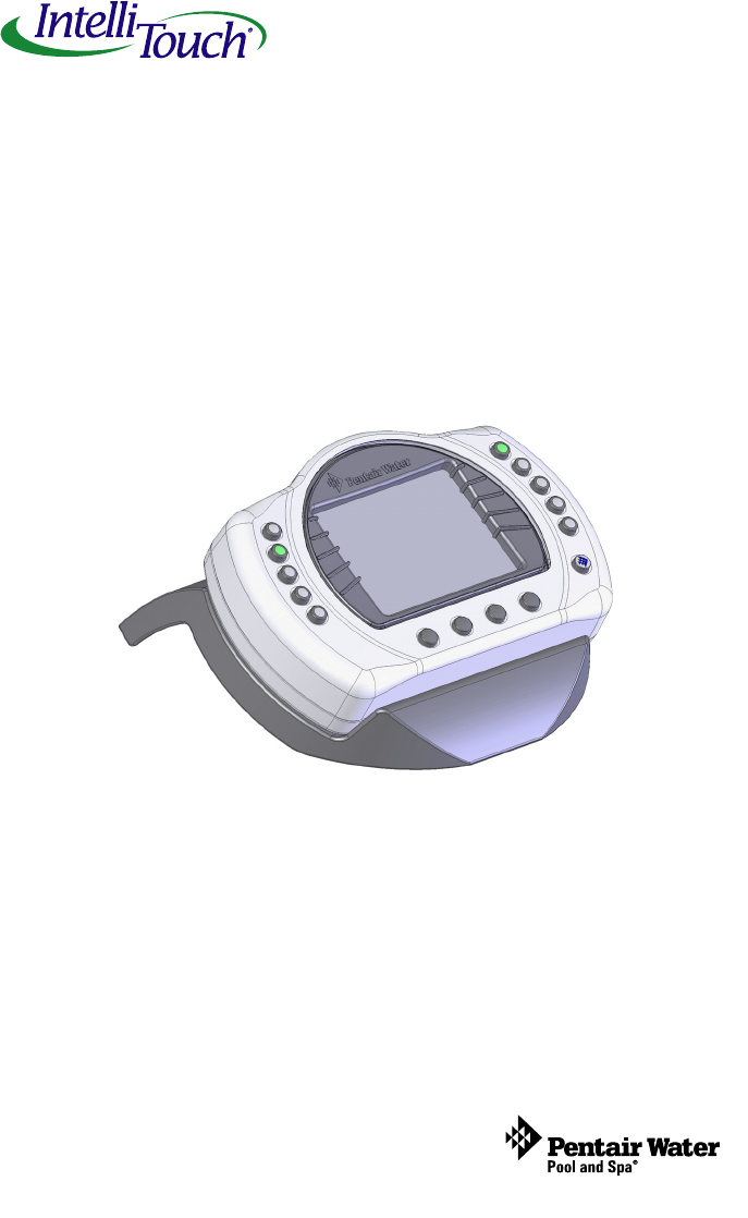
IntelliTouch® Pool & Spa
Control System
MobileTouch® Wireless Controller
pool/spa control system

MobileTouch Wireless Controller User’s and Installation Guide
MobileTouch Wireless Controller kit contents
The following items are included in the MobileTouch Controller kit. If any items
are missing please contact Technical Support.
• MobileTouch wireless controller
• AC/DC power adapter
• Cradle
• User’s and Installation Guide (this manual)
© 2008 Pentair Water Pool and Spa, Inc. All rights reserved.
1620 Hawkins Ave., Sanford, NC 27330 • (919) 566-8000
10951 West Los Angeles Ave., Moorpark, CA 93021 • (800) 553-5000
MobileTouch®, IntelliTouch®
and Pentair Water Pool and Spa® are trademarks and/or registered trademarks of Pentair Water
Pool and Spa, Inc. and/or its affiliated companies in the United States and/or other countries. Unless noted, names and brands
of others that may be used in this document are not used to indicate an affiliation or endorsement between the proprietors of
these names and brands and Pentair Water Pool and Spa, Inc. Those names and brands may be the trademarks or registered
trademarks of those parties or others.
i
CAUTION: IMPORTANT BATTERY INFORMATION
• Danger of explosion if battery is incorrectly replaced.
• Replace battery with the same type recommended by Pentair. Use Pentair
Battery Replacement Kit (P/N 520815Z).
•Rechargeable Lithium-ion battery disposal: Unwanted lithium ion
battery pack may be returned to your local recycling center or the
manufacturer for disposal.
• Dispose of used batteries according to the manufacturer’s instructions.
• Dismantling or opening the device (with the exception of the battery door)
or case will void warranty and may possibly cause electric shock.
FCC Regulatory Safety Notice - This equipment has been tested and found to comply with the
limits for a Class B digital device, pursuant to Part 15 of the FCC Rules. These limits are designed to
provide reasonable protection against harmful interference in a residential installation. This equipment
generates, uses and can radiate radio frequency energy and, if not installed and used in accordance
with the instructions, may cause harmful interference to radio communications. However,
there is no guarantee that interference will not occur in a particular installation. If this equipment does
cause harmful interference to radio or television reception, which
can be determined by turning the equipment off and on, the user is encouraged to try to correct the
interference by one or more of the following measures:
• Reorient or relocate the receiving antenna.
• Increase the separation between the equipment and receiver.
• Connect the equipment into an outlet on a circuit different from that to which the receiver is
connected.
• Consult the dealer or an experienced radio/TV technician for help.
• Modifications not expressly approved by the party responsible for FCC compliance could
void the user’s authority to operate the equipment.
Related manuals - Download the IntelliTouch User’s Guide (P/N 520102) at:
http://www.pentairpool.com/owners_manuals/controls
IntelliTouch_Pool_Spa_Cntrls_Instll_Guide.pdf
Technical Support
Sanford, North Carolina (8 A.M. to 5 P.M. ET)
Moorpark, California (8 A.M. to 5 P.M. PT)
Phone: (800) 831-7133 - Fax: (800) 284-4151
IC Regulatory Notice
Operation is subject to the following two conditions: (1) this device may not cause interference, and
(2) this device must accept any interference, including interference that may cause undesired
operation of the device.
P/N 520886 - Rev A - 07/24/2008
RF Exposure Requirements: This Device must not be co-located or operated in conjunction
with any other antenna or transmitter.

MobileTouch Wireless Controller User’s and Installation Guide
Contents
Charging the MobileTouch Wireless Controller ....................................... 2
Setting up the MobileTouch Wireless Controller ..................................... 4
MobileTouch Transceiver Antenna Location ........................................... 7
Installing the MobileTouch Transceiver .................................................. 8
Optional Serial COM Port Expansion Board ........................................ 13
MobileTouch Wireless Controller
The MobileTouch wireless controller provides the same functionality as
the IntelliTouch Indoor Control Panel. It has an operating range of up to
500 ft. from the MobileTouch antenna (Transceiver), which is typically
located near the IntelliTouch load center. The optimum wireless
transmit and receive range may be affected by physical obstructions,
(especially those containing metal), and geographical features.
The MobileTouch controller LCD (liquid crystal display) can be
sensitive to sunlight. When exposed for extended periods, the LCD
screen will heat up and turn black. If this happens, place the remote in
a shaded area and allow the screen to cool down. Do not attempt to
adjust the contrast or the screen will be unreadable when it eventually
cools. When used outside, keep the remote covered or in a shaded
area. Prolonged exposure to sunlight may permanently damage the
unit.
WARNING! Do not plug in the AC adapter to a power source
within five (5) feet of the pool and spa. Canadian installations require a
minimum of (3) meters from pool water. Do not recharge outdoors.
Only use Pentair approved AC adapter transformer.
The MobileTouch wireless controller is water resistant and can be
exposed to temporary splashing or wet hands. However, the controller
is not intended to be submersed. Remove unit immediately if it is
dropped in the water or exposed to rain. Store the unit indoors in a dry
environment. Be sure the gold charging contacts are dry before
charging.
MobileTouch Wireless Controller (Previous Model)
The previous model of the MobileTouch wireless controller and
Transceiver antenna cannot be used with the latest model of the
MobileTouch wireless controller and Transceiver antenna. Both models
cannot coexist in the same IntelliTouch system.
1
MobileTouch Wireless Controller User’s and Installation Guide
2
Charging the MobileTouch Wireless Controller
When you are not using the MobileTouch controller, place it in the
cradle to recharge the battery. This allows the battery to be fully
charged at all times.
To charge the MobileTouch controller battery
• Plug the AC adapter into an AC wall outlet.
• Insert the AC Adapter plug into the bottom of the cradle.
• Place the MobileTouch controller in the cradle.
Note: When the MobileTouch controller is placed in the cradle the
display and backlight will be on. After five minutes the backlight
will shut off. The MobileTouch unit and display are always on
when seated in the cradle. To turn the backlight on, press any
button.
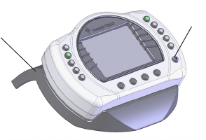
To use the MobileTouch wireless controller
1. Remove the MobileTouch wireless controller from the
cradle. Note: With AC power connected to the cradle, the
MobileTouch controller can be used while seated in the
cradle.
2. Press the Power On/Off button (front lower right-side) to
switch the unit on. The main screen is displayed. The LCD
backlight will turn off in five minutes if not in use. The
battery icon displays three solid bars, only when it’s fully
charged. Note: If the MobileTouch is not being used for
extended periods of time, press the Power On/Off switch
to turn the controller Off.
2
MobileTouch controller seated in cradle
Cradle Power On/Off button
MobileTouch Wireless Controller User’s and Installation Guide
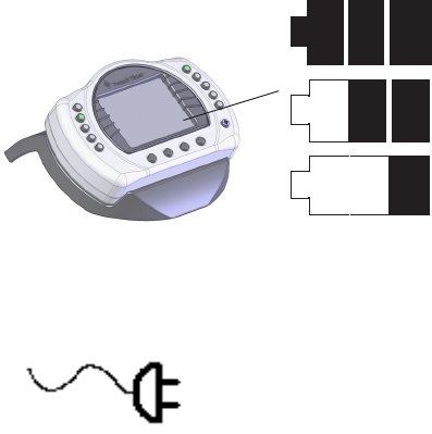
Main Screen Check Battery Icon
The check battery icon is located in the lower right corner of the main
screen. If the battery icon displays one or no bars or the screen is
blank, this may indicate that the battery cannot power the device and
needs recharging.
A complete battery charge takes about 3 to 4 hours. During battery
recharge, the battery icon bars scroll from right to left. After a
complete battery recharge, the battery icon is replaced with a power
plug icon, indicating the battery is fully charged and is now operating
on AC power from the cradle. Note: If the battery requires
replacement, only use Pentair replacement battery (P/N 520815Z).
Battery Icon
Sufficient charge left in the
batteries to operate device.
Three solid bars indicate
ample battery charge.
During battery recharge,
bars scroll right to left.
Batteries will deplete soon.
The power plug icon displays when the battery
is fully charged and the MobileTouch controller
is operating on AC power supplied from cradle
Power Plug Icon
3
MobileTouch Wireless Controller User’s and Installation Guide
4
Setting up the MobileTouch Wireless Controller
The following describes how to assign the MobileTouch wireless
controller a communication address for the first time and to add a
MobileTouch controller to a system with a controller already installed.
After connecting the Transceiver cable to the IntelliTouch load center
(see page 8), the system is ready to setup MobileTouch controller.
To manually setup the MobileTouch controller:
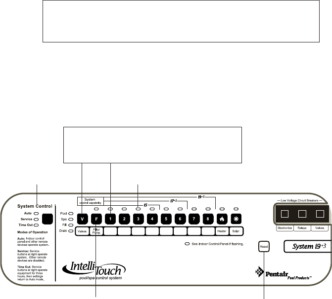
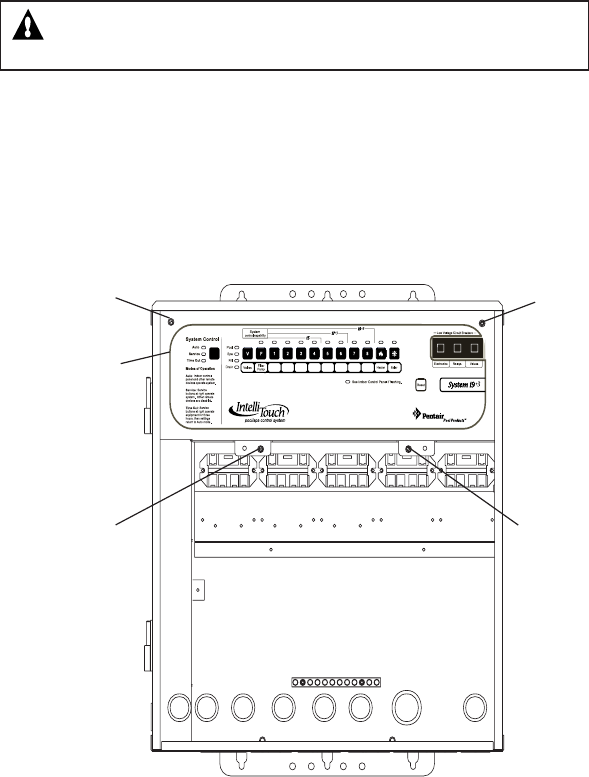
1. On the IntelliTouch Outdoor Control Panel, press the Reset
button (see below).
2. First Time MobileTouch install: The three red System
Control LEDs will be lit (solid). Wait a few seconds then
press the “F” Filter button. For IntellliTouch model i10+3,
press the “P” Pool Filter Pump button.
Add a MobileTouch with existing MobileTouch installed:
The three red System Control LEDs will be lit (solid). Wait
a few seconds then press the “V” button or “1” button.
3. The three red System Control LEDs and the auxiliary
button LEDs will begin cycling. Wait until the LEDs stop
cycling. The three System Control LEDs will start to blink
on and off. The IntelliTouch system is ready to assign an
address for the MobileTouch wireless controller; continue
with Step 4 on page 5.
IntelliTouch Outdoor Control Panel
Three System
Control LEDs Auxiliary LEDs
Reset
button
F button
(i5+3, i5S+3 i7+3,
i9+3S, i9+3D)
P button (i10+3D)
Note: Press
V or 1 button
to add a
MobileTouch controller with existing
MobileTouch controller(s) already installed.
MobileTouch Wireless Controller User’s and Installation Guide
5
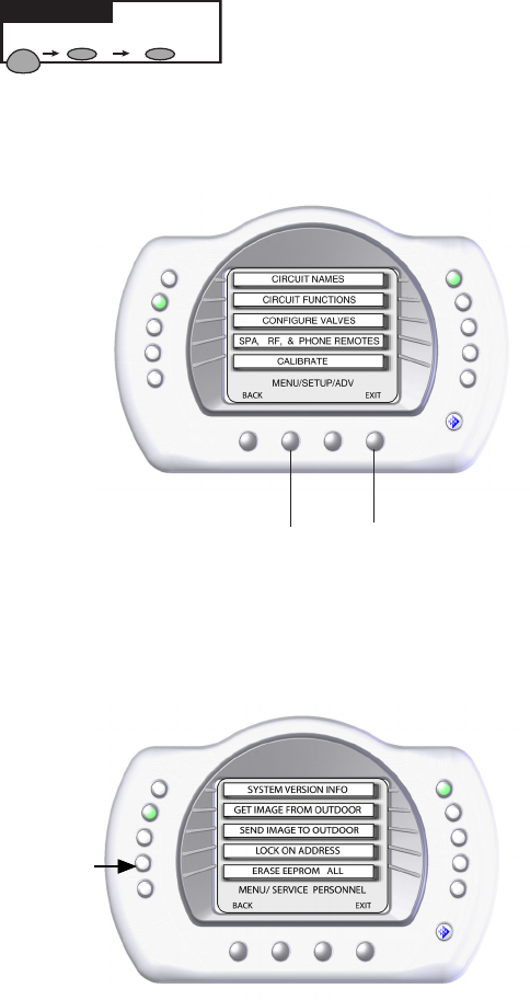
MENU SETUP ADVANCED
Getting There
Setting up the MobileTouch Wireless Controller (continued)
Go to the Advanced screen.
4. From the MobileTouch Advanced screen, press the lower
buttons 2 and 4 at the same time. The Service Personnel
screen is displayed.
5. Press the button next to LOCK ON ADDRESS to access
the next screen.
Press button 2 and 4 at the same time to
access the Service Personnel screen
MobileTouch Wireless Controller User’s and Installation Guide
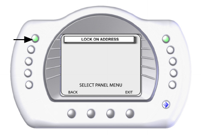
6. Press the button next to LOCK ON ADDRESS to assign a
unique frequency for the MobileTouch controller to avoid
interference from other wireless devices within range of the
MobileTouch transceiver.
7. After selecting “Lock On Address” the MobileTouch
controller is now ready to operate the IntelliTouch system.
The “Service Personnel” screen will be displayed.
8. Press Exit to return to the main screen or proceed with
Step 9 if you are adding another MobileTouch controller
while the IntelliTouch outdoor control panel LEDs are
flashing.
9. To add another MobileTouch controller at this time,
repeat Steps 4 (page 5) through 8 for each controller, if not,
continue with Step 10.
10. Return to the Load Center or Power Center. The System
Control LEDs will be flashing. Press the Reset button.
When the “Auto” LED is illuminated the process is complete
and the system is ready for operation.
6
MobileTouch Wireless Controller User’s and Installation Guide
7
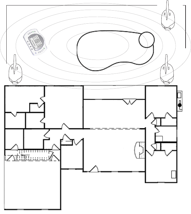
MobileTouch Transceiver Antenna Location
The Transceiver optimum wireless transmit and receive range may be
affected by physical obstructions, (especially those containing metal),
weather conditions, and geographical features.
The MobileTouch controller has an operating range of up to 500 ft.
(line-of-sight) from the MobileTouch Transceiver. The Transceiver kit
includes a 10 ft. connection cable. If needed, using extra cable, the
cable length can be lengthened to 300 ft. The recommended locations
for the Transceiver are shown below.
Recommended locations for Transceiver Antenna
LOAD
CENTER
Note: Only one MobileTouch controller Transceiver can be
used per IntelliTouch system.
Possible
antenna
location
Possible
antenna
location
Possible
antenna
location
MobileTouch Wireless Controller User’s and Installation Guide
Installing the MobileTouch Transceiver
The MobileTouch controller has an operating range of up to 500 ft.
(line-of-sight) from the MobileTouch Transceiver. The Transceiver kit
includes a 10 ft. connection cable. If needed, using extra cable, the
cable length can be lengthened to 300 ft. The recommended locations
for the Transceiver are shown on page 7.
To install the Transceiver:
1. Choose an installation location for the Transceiver near the
IntelliTouch load center.
2. Remove the two lower retaining screws from the
Transceiver and slide the Transceiver case up to remove it
from the back plate.
3. Remove the Transceiver circuit board from the back plate by
carefully lifting it up out of the back plate supports. Place the
circuit board on a clean dry surface away from direct
sunlight.
4. Mount the Transceiver back plate (see page 9) onto a flat
wooden surface, such as a wooden fence, or post. While
holding the back plate, install two lower mounting screws
through the back plate lower mounting holes. Tighten the
screws to secure the back plate in place. Install two screws
through the upper mounting holes.
5. Slide the Transceiver circuit board into the back plate into the
board side supports.
6. Route the Transceiver cable up through the bottom of the
back plate (see page 9) to the screw terminal connector.
7. Insert the four wires into the screw terminals of the
Transceiver connector. Using a small flat-blade screwdriver,
secure the wires with the screws. Make sure to match the
color coding of the four wires (see page 12 for wiring
diagram).
8. Carefully slide the case over the Transceiver antenna and
secure it to the back plate with the two lower retaining
screws.
9. Proceed with “Connecting the Transceiver cable to the
IntelliTouch Personality board” on page 10.
8
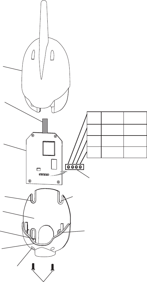
MobileTouch Wireless Controller User’s and Installation Guide
Screw terminals
Transceiver circuit board
Back plate
Retaining screws
Case
Lower exit hole (left side)
Antenna
Upper mounting point
(screw)
Transceiver Module
9
1DNGKLB
2TD-NRG
3TD+LEY
4V51DER
Lower mounting
point (screw)
Lower mounting
point (screw)
Upper mounting point
(screw)
Left-side Transceiver
circuit board support
MobileTouch Wireless Controller User’s and Installation Guide
WARNING Switch OFF the main system power to the Load Center
before making any connections.
1. Unlatch the two enclosure door spring latches, and open the
door.
2. Remove the two retaining screws securing the high voltage
cover-panel, and remove it from the enclosure.
3. Loosen the two access screws securing the control panel.
10
Panel retaining
screw
(Cover-panel
not shown)
Access
screw
Retaining
screw
Access
screw
Control panel
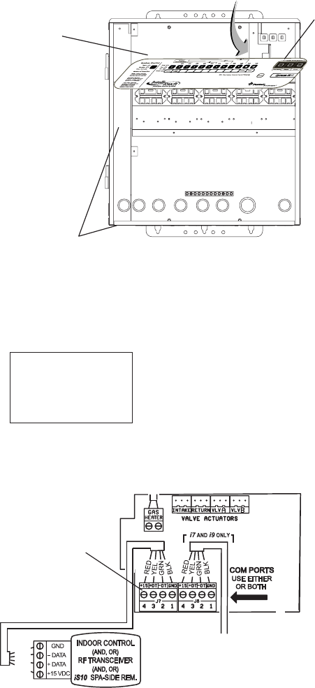
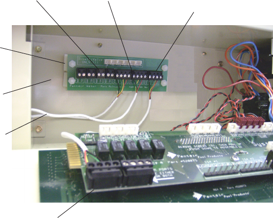
Connecting the Transceiver cable to the Personality board
Load Center
4. Lower down the hinged control panel to access the
Personality board.
MobileTouch Wireless Controller User’s and Installation Guide
5. Route the transceiver cable into the lower plastic grommet,
up through the low voltage raceway to the Personality board.
6. Insert the four wires into the screw terminals of the COM
PORT plug located on the Personality board as shown below.
Using a small flat-blade screwdriver, secure the wires with
the screws. Make sure to match the color coding of the four
wires:
Pin 4 - Red = +15
Pin 3 - Yellow = +DT
Pin 2 - Green = -DT
Pin 1 - Black = GND
11
BLK
GRN
YEL
RED
IntelliTouch Personality
board COM PORTS
(J7/J8) screw terminal
connector
Raceway
Control panel
Personality
board
Note: If there no available COM port
terminals for the Transceiver cable
plug connector to plug in to, the
optional Serial COM Port Expansion
Board (P/N520818) can be used (see
page 13). Multiple wires may also be
inserted into a single screw terminal.
MobileTouch Wireless Controller User’s and Installation Guide
7. After the connection has been completed, close the control
panel into its original position and secure it with the two
access screws.
8. Close the IntelliTouch front panel and secure it with the two
retaining screws.
9. Close the IntelliTouch Load Center front door. Fasten the
two spring latches.
10. Switch the power on to the IntelliTouch Load Center.
11. Proceed to “Setting up MobileTouch and IntelliTouch”
on page 4.
12
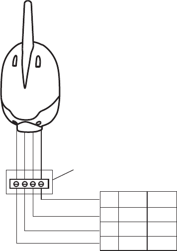
Personality board COM PORT Pin configuration
MobileTouch
outdoor wireless
transceiver located
within 10 feet from
IntelliTouch Load
Center
COM PORT screw
terminal connector
1DNGKLB
2TD-NRG
3TD+LEY
4V51DER
MobileTouch Wireless Controller User’s and Installation Guide
13
Optional Serial COM Port Expansion Board
(for use with IntelliTouch® control systems)
If there is not an available COM port for the Transceiver cable plug on
the IntelliTouch Personality board, the optional Serial COM port
Expansion Board (P/N 520818) can be used for additional COM ports
connections.
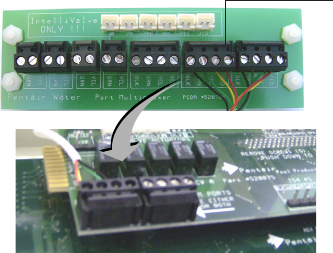
Mounting the Expansion Board
1. Remove the inside terminal connectors (with wires attached)
from the Expansion board and connect it to a COM port on
the Personality board.
Note: If this a new Load Center installation, you’ll have
to remove one of the existing (empty) terminal connectors
from the Personality board to allow for the Expansion
board terminal connector. You can place the (empty)
connector onto the available COM port on the
Expansion board.
2. Mount the Expansion board on to the back wall in the low
voltage compartment of the IntelliTouch load center using the
four adhesive backed supports.
3. Proceed to “Connecting the Transceiver cable plug to the
Serial COM Port Expansion Board,” on page 14.
Remove this terminal connector
and connect it to an available COM
port on the IntelliTouch Personality
board.
Personality Board
MobileTouch Wireless Controller User’s and Installation Guide
14
Connecting the Transceiver cable plug to the Serial Com
Port Expansion Board
Connect the Transceiver cable plug onto one of the available Serial
COM port expansion board connector terminals.
Note: If you have existing accessories (IntelliChlor, IntelliFlo)
connected to the IntelliTouch Personality board and need to free
up connectors for additional equipment, remove one of the existing
connectors (with the attached wires to equipment) from the
Personality board and plug it into an available connector on the
Expansion board COM port (as shown below).
Cables to
accessories
(IntelliChlor,
Indoor Control
Panel etc.)
Low voltage
compartment
Expansion
board
adhesive
backed
supports (x4)
Connect existing
accessory connectors
wires here
Connect to COM port on
IntelliTouch Personality
board
Connector from the Expansion board
Connect IntelliFlo
wires to two-pin
terminal connector
MobileTouch Wireless Controller User’s and Installation Guide
15
Notes
MobileTouch Wireless Controller User’s and Installation Guide
Notes
16
MobileTouch Wireless Controller User’s and Installation Guide
Notes
17

MobileTouch Wireless Controller User’s and Installation Guide
*520886*
P/N 520886 - Rev A