Pentair Mt Users Manual MegaTherm Pool Heater (2000 5000)
MT to the manual 584103c1-e575-4f5a-a187-7f714a901a05
2015-02-06
: Pentair Pentair-Mt-Users-Manual-517981 pentair-mt-users-manual-517981 pentair pdf
Open the PDF directly: View PDF ![]() .
.
Page Count: 20
Installation
and Operation
Instructions for
MegaTherm
Pool Heating Boiler
Model MT
Sizes 2000-5000
FOR YOUR SAFETY: This product must be installed and serviced by a professional service technician,
qualified in hot water boiler installation and maintenance. Improper installation and/or operation could
create carbon monoxide gas in flue gases which could cause serious injury, property damage, or death.
Improper installation and/or operation will void the warranty.
WARNING
If the information in this manual is not followed exactly, a fire or explosion may result
causing property damage, personal injury or loss of life.
Do not store or use gasoline or other flammable vapors and liquids in the vicinity of this or
any other appliance.
WHAT TO DO IF YOU SMELL GAS
• Do not try to light any appliance.
• Do not touch any electrical switch; do not use any phone in your building.
• Immediately call your gas supplier from a nearby phone. Follow the gas supplier's
instructions.
• If you cannot reach your gas supplier, call the fire department.
Installation and service must be performed by a qualified installer, service agency, or gas
supplier.
IMPORTANT: Store these instructions in the packet provided on the boiler
P/N 472644 Rev A - 05/22/06
IMPORTANT SAFETY INSTRUCTIONS
READ AND FOLLOW ALL INSTRUCTIONS
SAVE THESE INSTRUCTIONS
®
TM

Page 2 Pentair Water Commercial Pool and Spa
TABLE OF CONTENTS
SECTION 1.
General Information
1A. Introduction................................................... 3
SECTION 2.
Installation
2A. Boiler Placement .......................................... 3
2B. Installation of Indoor Boilers ......................... 4
2B-1. Combustion Air Supply ................................. 4
2B-2. Venting ......................................................... 5
2C. Installation of Outdoor Water Units............... 5
2D. Freeze Protection ......................................... 6
2E. Gas Supply and Piping ................................. 6
2F. Electrical Wiring ............................................ 7
2G. Piping of System to Boiler ............................ 7
2H. General Water Piping ................................... 7
2I. Boiler By-Pass Piping ................................... 8
2J. Automatic Chlorinators ................................. 8
2K. Pressure Switch ........................................... 8
SECTION 3.
Operation
3A. Initial Start Up ............................................... 9
3A-1. Initial Filter Cycle on a New Pool .................. 9
3A-2. Starting Instructions ...................................... 9
3A-3. Hi-Limit Checkout ....................................... 10
3B. To Start Up System
(See Section 3A for Initial Start Up) ............ 10
3C. To Turn Off Boiler ....................................... 10
3D. Spring and Fall Operation ............................ 10
3E. Winter Operation ......................................... 10
3E-1. Draining Boiler Before Freezing ................... 10
3E-2. Improper Use of the Boiler ........................... 10
3F. Time Clock Operation .................................. 11
3G. Spa (Hot Tub) Safety Rules ......................... 11
3H. Periodic Service .......................................... 11
3I. Pool Water Chemistry ................................. 11
SECTION 4.
Maintenance
................................................................... 12
SECTION 5.
Troubleshooting and Analysis of
Service Problems
................................................................... 12
SECTION 6.
Conversion of Model MT Pool Boilers
From Indoor to Outdoor Models
6A. SECTION I ................................................. 14
6B. SECTION II ................................................ 14
SECTION 7.
Parts Description and
Order Numbers
................................................................... 16
Pentair Technical Support
Sanford, North Carolina (8 A.M. to 5 P.M.)
Phone: (800) 831-7133
Fax: (919) 566-8920
Moorpark, California (8 A.M. to 5 P.M.)
Phone: (800) 831-7133
Fax: (800) 284-4151
Web sites: visit www.pentairpool.com and www.staritepool.com

MegaTherm Commercial Pool Heating Boiler Page 3
SECTION 1.
General Information
IMPORTANT WARNING:
The MegaTherm Model MT commercial pool
boilers must be used with potable water only.
For pools containing salt water, a specially
equipped boiler must be used. Consult your
distributor or factory representative. The pool
boiler must be installed in accordance with the
procedures in this manual, or the warranty
could be voided. Consult local building codes
and ANSI bulletin Z223.1 or in Canada CAN1-
B149 before proceeding with the installation.
Any modification to the boiler, its gas controls,
gas orifices, wiring or draft diverter may void
the warranty. Consult the factory before making
any modifications.
1A. Introduction
This manual provides information for the
installation and operation of Model MT Pool Boilers. It
is strongly recommended that all application and
installation procedures be reviewed completely before
proceeding with the installation. Consult the Pentair
Water Commercial Pool and Spa technical support
(see page 2), or your local representative, with any
problems or questions regarding this equipment.
Experience has shown that most operating problems
are caused by improper installation.
Model MT boilers are offered in two
configurations: an indoor version and an outdoor
version. The indoor version is convertible for outdoor
use with the installation of a conversion kit as
described in Section 6 of this manual. The two
configurations are shown in Figure 1.
Some accessory items are shipped in separate
packages. Verify receipt of all packages listed on the
packing slip. Inspect everything for damage
immediately upon delivery, and advise the carrier of
any shortages or damage. Any such claims should be
filed with the carrier. The carrier, not the shipper, is
responsible for shortages and damage to the shipment
whether visible or concealed.
SECTION 2.
Installation
2A. Boiler Placement
The Model MT boiler must be placed to provide
clearances on all sides for maintenance and inspection.
There must also be minimum distances maintained
from combustible surfaces.
Figure 1. Boiler Configuration - Series MT.

Page 4 Pentair Water Commercial Pool and Spa
All boilers must be installed on a non-combustible
floor. Under no circumstances can boilers be installed
on carpeting. The National Fuel Code allows a boiler
to be placed on other than a non combustible surface
when such an installation complies with the local
codes. This code specifies the surface under the boiler
be protected with hollow masonry no less than 4" thick,
covered with sheet metal at least 20 gage in thickness.
Such masonry must be laid with ends unsealed, and
joints matched in such a way as to provide a free
circulation of air from side to side through the masonry
(see Figure 2).
cause accelerated deterioration of controls and
electrical components.
3. Exhaust Fans or Vents: Any equipment which
exhausts air from the boiler room can deplete the
combustion air supply or reverse the natural draft
action of the venting system. This could cause
flue products to accumulate in the room.
Additional air must be supplied to compensate
for such exhaust. The information in Table 2 is
not applicable in installations where exhaust
fans or blowers of any type are used. Such
installations must be designed by qualified
engineers.
Figure 2. Non-Combustible Base.
2B. Installation of Indoor Boilers
2B-1. Combustion Air Supply
1. The boiler location must provide sufficient air
supply for proper combustion, and ventilation of
the surrounding area as outlined in the latest
edition of ANSI standard Z223.1 or, in Canada
CAN1-B149, and any local codes that may be
applicable. Inadequate combustion air supply
may result in incomplete combustion and
consequent sooting of the heat exchange and
unsafe operation of the boiler.
2. In general, (in the U.S.), these requirements
specify that equipment rooms which represent
confined spaces should be provided with two
permanent air supply openings communicating
directly through the wall to outside air; one
within 12 inches of the ceiling, the other within
12 inches of the floor. Each opening should have
a minimum free area of one square inch per
4,000 BTUH input of the total input rating of all
appliances in the enclosed area. These
requirements differ in Canada. Consult the
National Standard of Canada CAN1-B149 for
details. See Table 2 for recommended air supply
for U.S. models. An improperly ventilated
equipment room can get excessively hot and
Clearance Indoor Outdoor
From (Inches) (Inches)
Top 24 —
Water Conn. Side 24 24
Opposite Side 24 24
Front 48 48
Rear 24 24
Vent 6 —
Table 1. Minimum Boiler Clearance
From Combustible Surfaces
Indoor Each Opening*
Size (Square Inches)
2000 500
2450 613
3050 763
3500 875
4050 1013
4500 1125
5000 1250
Net Free Area in Square Inches*
*Area indicated is for one of two openings: one at floor level
and one at the ceiling, so the total net free area would be
double the figures indicated. For all other conditions, refer to
latest edition of ANSI A223.1.
NOTE: Check with louver manufacturers for Net Free Area of
louvers. Correct for screen resistance to the Net Free Area if
a screen is installed. Check all local codes applicable to
combustion air.
Table 2. Minimum Recommended Air
Supply to Equipment Room.
4. If a blower or fan is used to supply air to the
equipment room, the installer should make sure it
does not create drafts which could cause
nuisance shut-downs of the pilot. If a blower is
necessary to provide adequate combustion air to
the boiler, a suitable switch or equivalent must
be wired into the boiler control circuit to prevent
the boiler from firing unless the blower is
operating.
5. The boiler must be completely isolated and
protected from any source of corrosive chemical
fumes such as emitted by trichlorethylene,
perchlorethylene, chlorine, etc.
Blocks must provide solid base and be braced so they cannot
slip out of place. Air openings in blocks must be arranged to
provide unobstructed opening through entire width or length of
base.

MegaTherm Commercial Pool Heating Boiler Page 5
2B-2. Venting
1. Model MT boilers have built-in draft diverters for
natural draft operation and must not be
connected into any portion of a mechanical draft
system under positive pressure. The flue outlet
must be connected to a clear, unobstructed vent
of adequate capacity terminating above the
highest point of the building with an approved
vent cap. The venting system should be installed
according to the latest edition of ANSI Z223.1
(or CAN1-B149) and any local codes having
jurisdiction.
IMPORTANT NOTE: Do not use sheet metal
screws at the snap lock joints of Type B gas vents.
2. Do not weld or fasten the vent pipe to the boiler
draft hood. The weight of the stack must not rest
on the boiler. The draft hood and top must be
easily removable for normal boiler service and
inspection.
3. Avoid long horizontal runs of the vent pipe, and
too many 90 degree elbows, reductions and
restrictions. Horizontal runs should have at least
a 1/4” rise per foot in the direction of flow. A
vent connector shall be supported for the design
and weight of the material employed to maintain
clearances and prevent physical damage and
separation of joints.
4. Avoid terminating boiler vents near air
conditioning or air supply fans. The fans can
pick up exhaust flue products from the boiler and
return them inside the building, creating a
possible health hazard. A minimum of 4 feet
horizontal distance must be maintained from
electric meters, gas meters, and relief equipment.
5. Always use double-wall or insulated vent pipe
(Type B or equivalent). In cold weather,
uninsulated outside vents can chill the rising flue
products, blocking the natural draft action of the
venting system. This can create a health hazard
by spilling flue products into the boiler room.
6. Avoid oversize vent piping or extremely long
runs of the pipe which may cause excessive
cooling and condensation. Rule of Thumb: The
total length of the vent, including the connector
and any offset, should not exceed 15 feet for
every inch of vent diameter. Longer total lengths
shown in venting tables are based on maximum
capacity, not condensation factors.
7. When the installation of a draft fan is necessary
in the venting system to which a Model MT
boiler is to be connected, the installation should
be engineered by competent personnel following
good engineering practices. The draft fan
supplier should be consulted for correct size. The
installation should be in accordance with the
latest edition of ANSI Z223.1 and any local
codes having jurisdiction. When a draft fan is
installed, a suitable draft switch must be used
and wired into the boiler control circuit at
terminal designated “Field Interlock,” to prevent
firing of the unit unless a positive draft has been
established (see Figure 3).
Figure 3. Draft Fan Wiring Diagram.
2C. Installation of Outdoor Units
1. Locate the boiler to provide the minimum
clearances as listed in Section 2A, “Boiler
Placement.”
2. Do not locate the boiler in an enclosure or wall
recess. Avoid locations where wind deflection
off structures might cause down draft. When
such wind conditions are possible, locate the unit
at least three (3) feet from the structures.
3. Never install the boiler under any kind of roof
overhang. Do not locate the unit below or
adjacent to any doors, windows, louvers, grills,
etc. which communicate in any way with an
inhabited area of a building. Even though such
communication might be through another
structure such as a garage or utility room (see
Figure 4).
Figure 4. Incorrect Outdoor Installation.

Page 6 Pentair Water Commercial Pool and Spa
4. Liquified petroleum is heavier than air.
Therefore, the pool boiler should not be installed
in pits or other locations where gas could
accumulate. The boiler should be located a safe
distance from LP gas storage and filling
equipment. Consult local codes and fire
protection authorities for advice relative to
specific installation restrictions.
2D. Freeze Protection
Boiler installations are not recommended in areas
where the danger of freezing exists unless proper
precautions are made for freeze protection.
2E. Gas Supply and Piping
Review the following instructions before
proceeding with the installation.
1. Verify that the boiler is fitted for the proper type
of gas by checking the rating plate. Model MT
boilers are normally equipped to operate below a
2000 foot altitude. Boilers equipped to operate at
higher altitudes have appropriate stickers or tags
attached.
2. Use the figures in Table 3 to provide adequate
gas piping (check local code for BTU capacity
required).
must be isolated from the gas supply piping
system by closing its individual manual gas
shutoff valve during any pressure testing of the
gas supply piping system at test pressures equal
to or less than 1/2 psig.
5. Provide gas supply pressure to the boiler as
follows:
Natural Propane
Min. (inches water column) 7 11
Max. (inches water column) 9 14
Note: The boiler and all other gas appliances
sharing the gas supply line must be firing at maximum
capacity to properly measure the inlet supply pressure.
Low gas pressure could be an indication of an
undersized gas meter and/or obstructed gas supply
line.
6. The correct burner manifold gas pressure is
stamped on the rating plate. The regulator is
preset at the factory, and normally requires no
further adjustment.
7. The gas manifold and control assembly was
tested and conforms to the safe lighting and other
performance criteria specified in the latest
editions of ANSI Z21.13 and CGA 3.3 Low
Pressure Boiler Standard.
8. Before operating the boiler, the complete gas
supply system and all connections must be tested
for leaks using a soap solution. Do not use raw
flame.
Caution
Since some leak test solutions, including soap
and water, may cause corrosion or stress
cracking, the piping must be rinsed with water
after testing, unless it has been determined
that the leak test solution is noncorrosive.
Distance from Gas Meter or
Natural and LP Gas
0-100' 100-200' 200-300'
Indoor Outdoor
Size Size Nat. LP Nat. LP Nat. LP
2000 — 2½ 2 3 2½ 3 3
2450 2200 3 2½ 3 2½ 3½ 3
3050 2800 3 2½ 3½ 3 3½ 3
3500 3200 3 2½ 3½ 3 4 3½
4050 3600 3½ 3 4 3½ 4 3½
4500 4000 3½ 3 4 3½ 5 4
5000 4500 4 3½ 4 3½ 5 4
NOTES:
These figures are based on ½" water column pressure drop.
Check supply pressure and local code requirements before
proceeding with work.
Pipe fittings must be considered when determining gas pipe
sizing.
3. A trap (drip leg) must be provided ahead of the
gas controls (see Figure 5). Where required by
code, provide a second manual gas shutoff valve.
Do not remove manual valve furnished with the
unit.
4. The boiler and its individual shutoff valve must
be disconnected from the gas supply piping
system during any pressure testing of that system
at test pressures in excess of 1/2 psig. The boiler
Figure 5. Tee Fitting Sediment Trap.

MegaTherm Commercial Pool Heating Boiler Page 7
Arrangement of gas train components for on-off
firing are shown schematically in the Gas Piping
Diagram (see Figure 6).
2F. Electrical Wiring
WARNING
The boiler must be electrically grounded in
accordance with the most recent edition of the
National Electrical Code, ANSI/NFPA 70, and
in Canada, follow Canadian Electrical Code
CSA C22.1. Do not rely on the gas or water
piping to ground the metal parts of the boiler.
Frequently, plastic pipe or dielectric unions
isolate the boiler electrically. Service and
maintenance personnel who work on or around
the unit may be standing on wet floors and
could be electrocuted by a poorly grounded
boiler.
1. Check boiler wiring and pump for correct volt
age, frequency and phase. If the pump circuit is
other than 115V, check to see that the boiler is
provided with an appropriate transformer.
2. Wire the boiler and pump exactly as shown in
the wiring diagram supplied with the boiler.
3. The pump and boiler must be electrically
interlocked so the boiler cannot come on unless
the pump is running.
4. All field installed electrical safety devices and all
field installed devices (draft switches, relays,
timers, etc.) can be connected to the boiler
wiring at points shown in the wiring diagram
designated “Field Interlock.”
5. Auxiliary Time Clock Wiring. If a time clock is
used to control the filter pump operation, a
separate switch must be used to shut off the
boiler at least 15 minutes before the filter pump
is shut off. Wire the separate switch (sometimes
called a “Fireman Switch”) at the points shown
on the internal wiring diagram as “Field
Interlock.”
2G. Piping of System to Boiler
1. Be sure to provide gate valves at the inlet and
outlet to the boiler so it can be readily isolated
for service.
2. The pressure relief valve must be installed in the
tapped opening provided, or on a “Tee” fitting
when provided, in the boiler outlet header with
its outlet piped to a drain or floor sink. Special
attention must be given to relief valve settings in
installations where the boiler is located on the
ground floor of a tall building. The static
pressure of the system is elevated, and could
cause the relief valve to leak. Where no special
setting of the relief valve is ordered, the factory
will furnish a 75 psi setting. Never reduce the
relief valve opening. If necessary, install the
relief valve in a Tee immediately past the boiler
outlet. The weight of all water and gas piping
should be supported by suitable hangers or floor
stands. Check piping diagrams with local
applicable plumbing, heating and building
safety codes.
2H. General Water Piping
1. Plastic fittings, grids, or other elements of the
filter system are subject to damage by the
momentary “back syphoning” of hot water when
the pump stops. To prevent this backflow, install
a swinging gate check valve in the piping
between the filter and the boiler.
2. No Hartford Loop is required for anti-syphon
protection.
3. No water flow adjustments are required except
when a manual bypass valve is installed.
4. Do not install any valve or other variable
restriction in the return piping between the boiler
outlet and the pool.
5. The outlet pipe is carrying a large volume of
water which has bypassed the boiler combined
with a small volume of very hot water.
Note:
Main Gas Valves Incorporate
Gas Pressure Regulators
* Standard on sizes 3050-5000 (AGA models).
** Sizes 2000 & 2450 use one pilot gas valve.
†Sizes 2000, 2450 & 3050.
Figure 6. Gas Piping Diagram.
Page 8 Pentair Water Commercial Pool and Spa
Therefore, the temperature difference between
the inlet and out pipes will be so small as to be
difficult to sense by touching the two pipes.
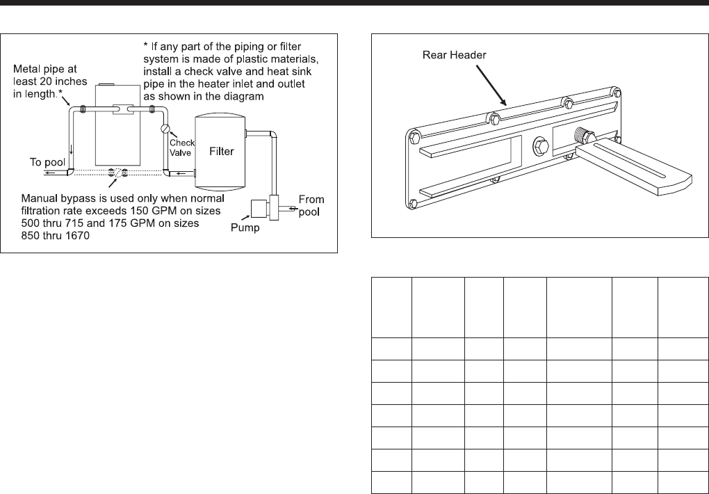
2I. Boiler By-Pass Piping
All Model MT pool boilers are equipped with an
automatic flow control valve. Do not install a manual
bypass valve unless the normal filtration rate exceeds
300 GPM. If the normal filtration rate exceeds that
figure:
1. Install the manual bypass valve as illustrated in
Figure 7.
2. Install a thermometer in the threaded opening in
the rear header as shown in Figure 8.
3. Set the manual bypass valve as follows:
a. Clean or backwash the filter completely.
b. Close the manual bypass valve completely.
c. Close the boiler’s main gas valve.
d. Start the filtration system with all valves set
for normal filtration.
e. After 3 minutes, record the thermometer
reading (this is the pool water temperature).
f. Open main gas valve and turn the
thermostat to its highest setting to start the
boiler.
g. Gradually open the bypass valve until the
temperature difference shown in column 6
of Table 4 is achieved. For example, if the
temperature reading in Step “e” was 60
degrees, and the boiler is a Model 3500, the
thermometer should read 75 degrees. Make
sure this temperature difference remains
constant for at least 5 minutes.
h. Remove the handle from the bypass valve
to prevent anyone from changing the
setting. The automatic flow control valve
will maintain proper flow through the
boiler regardless of the reduced water flow
due to a dirty or clogged filter.
2J. Automatic Chlorinators
A concentration of chlorine in the boiler can be
very destructive. Therefore, the following rules
regarding the installation and operation of automatic
chlorinators must be followed.
1. The chlorinator should be installed so that it
introduces the gas or solution downstream from
the boiler.
2. The chlorinator should be wired so that it cannot
operate unless the filter pumps running.
3. The chlorinator should be provided with an anti-
syphoning device so that when the pump shuts
off, chlorine will not syphon back into the boiler.
4. When the chlorinator is installed in the system
where the chlorine flows through the boiler,
corrosion can occur. Excessive concentrations of
chlorine, caused by improper adjustment or
failure of the chlorination equipment, can cause
boiler damage which is not covered by the
warranty.
2K. Pressure Switch
The pressure switch on the boiler is factory set at
4 psi. Do not tamper with the switch unless the boiler
is installed more than 3 feet below the surface of the
Figure 7. Manual By-Pass Installation.
Figure 8. Thermometer Location.
Bypass Min. Max. Temp.
Spring Flow Bypass Rise
Indoor Outdoor Part Color Req'd Valve at Rear
Size Size No. Code (GPM)Cap. (GPM) Header
2000 ------ S220 Black 110 300 15
2450 2200 S221 White 134 300 15
3050 2800 S221 White 167 300 15
3500 3200 S222 Brown 191 300 15
4050 3600 S222 Brown 221 300 15
4500 4000 S222 Brown 246 300 15
5000 4500 S222 Brown 273 300 15
Table 4. By-Pass Valve Adjustments.

MegaTherm Commercial Pool Heating Boiler Page 9
pool. If this condition exists, follow this procedure to
adjust the switch:
1. With the boiler on, the filter pump running and
the filter clean, slowly increase the pressure
setting until the boiler shuts off. Slowly decrease
the pressure setting until the boiler comes back
on. Decrease the pressure setting another 2 psi to
complete the switch setting.
2. Test the setting by closing the manual gas valve
and turning off the filter pump. Turn the
thermostat to the high setting and slowly open
the manual gas valve. The boiler should not try
to fire when the filter pump is off.
If the boiler is installed more than three feet
above the pool level, install an eyeball fitting on the
end of the return line to the pool to create adequate
back pressure that the boiler to operate the pressure
flow safety switch. Never reduce the factory setting of
the pressure switch. For special installation problems,
consult the factory.
SECTION 3.
Operation
3A. Initial Start-Up
3A-1. Initial Filter Cycle on a New Pool
On a newly constructed pool, be sure to run the
filter pump long enough to completely "turn-over" the
pool water before turning on the boiler. This will
insure that any dirt and residue from the construction
will be removed. The filter may clog rapidly during
this period, causing the boiler to severely cycle if it
is on.
3A-2. Starting Instructions
1. Check the following installation details before
proceeding:
a. Has the required air supply been provided?
b. Is the boiler properly vented?
2. Be sure the filter is clean.
3. Start the filter pump.
Before placing the boiler in operation, the
automatic safety shutoff devices must be
checked. Once the unit is connected to the gas
piping and after all of the requirements in
Section 2 have been met, follow this procedure:
a. Before beginning the tests, make sure the
main manual gas valve, and any other firing
valves are in the OFF position.
b. Make sure the power switch on the boiler is
in the “ON” position. After placing the
manual pilot valves in the open position, and
resetting all safety devices (high limit,
pressure switch, Low-Water-Cutoff, etc.),
pilots can be lit following the procedure
located on the boiler rating plate.
c. Once the pilots are lit and have been
established for five minutes, the flame
failure response time should be checked as
follows:
System 16: (Electronically supervised
standing pilot system standard on propane
gas). Extinguish the pilot flame by placing
the manual pilot valve in the closed
position, and, at the same time, begin
recording the time it takes for the output
signal from the electronic ignition control
to be interrupted. Refer to the electrical
drawing supplied with the boiler for wiring
details. The signal interruption can be
detected either with a test light or a
voltmeter. Because the ignition controls are
in series, the control just upstream of the
gas valves should be tested first. Under no
circumstances should the response time
exceed 5 seconds.
System 18: (Intermittent ignition supplied
only for natural gas). With this system,
pilots are automatically lit when the
thermostat calls for heat. The pilots are
permitted a trial period for ignition, then
the system is locked out if it fails to light.
To retry ignition, power to the boiler must
be momentarily interrupted. After the pilot
is initially lit, the trial for ignition time
should be checked by turning off pilot gas,
and, at the same time, monitoring the time
it takes for the audible sparking at the pilot
burner to stop. Under no circumstances
should the trial for ignition exceed 15
seconds because electronic ignition controls
are in series. The control just upstream of
the gas valves should be tested first (refer
to the electrical drawing supplied with the
unit).
Once the trial for ignition period has been
checked, the controls should be reset and
the flame failure response time checked
by following the procedure given for
system 16.
4. With the pilots lit, initial activation of the main
burners can be achieved by slowly opening the
main manual valve. The result should be a
smooth lighting of the main burners.

Page 10 Pentair Water Commercial Pool and Spa
3A-3. Hi-Limit Checkout
After running the boiler for a long enough period
to bring the water temperature within the range of the
hi-limit, slowly back off the high limit setting until the
unit shuts off. The main burners should re-ignite when
the hi-limit is turned back up to its original setting.
The high limit should now be reset and the boiler
run until it shuts off automatically on high limit.
Now that all tests of the safety shutoff devices
have been completed, refer to Section 3B for the
proper settings of temperature controls.
NOTE: Should any of the controls fail to
function properly, consult the factory or your gas
company representative.
3B. To Start Up System
(See Section 3A for Initial Start Up)
Start up boiler:
1. Be certain system pump is running.
2. Lighting instructions are provided on the rating
plate and in the User’s Manual and are as
follows:
a. Turn off main electrical switch.
b. Turn off all manual gas valves and wait
five minutes.
c. Set aquastat or thermostat to lowest setting.
d. Turn manual pilot valve to "ON." For
standing pilot system, press on pilot relay
knob, light pilot and keep relay knob
depressed for one minute then release.
Once the pilot is lit, the power will be
supplied to the gas valve(s) upon activation
of the aquastat.
e. Slowly turn manual gas valve to "ON."
f. Reset all safety switches (manual reset high
limit, low water cutoff, etc.).
g. Turn on main electric switch.
h. Set temperature controller (aquastat) to
desired temperature. Pilot will light
automatically (intermittent ignition pilot
system) and ignite main burners whenever
the aquastat calls for heat.
i. Adjust the pool aquastat as follows:
When the pool water has reached the desired
temperature, as measured with an accurate
thermometer, decrease the aquastat setting with a
small screwdriver until the boiler shuts off. The pool
boiler will maintain the existing pool water
temperature automatically.
3C. To Turn Off Boiler
1. Turn off main electrical switch.
2. Close all manual gas valves.
3D. Spring and Fall Operation
When the pool is not going to be used for a long
period of time, turn the aquastat down to
approximately 70o F. This will prevent the pool and
surrounding ground from becoming chilled, save on
fuel costs, and also permit the pool water temperature
to be raised back to swimming temperature in a
shorter period of time.
The pool water temperature should not be
maintained below 70o F. Colder water will cause
condensation to form on the heat exchanger when the
boiler does fire. Prolonged operation at a lower
temperature will cause the boiler to foul externally.
See “Improper Use of Boiler.”
3E. Winter Operation
To shut down the boiler for longer periods, turn
both the manual gas valve and pilot gas valve to OFF.
Where the danger of freezing does not exist, the
normal filter cycle should be continued all year long to
circulate water through the system even when the
boiler is turned off or shut down completely.
3E-1. Draining Boiler Before Freezing
If the boiler is located where it will be exposed
to freezing temperatures, it should be drained before
the first frost. Drain the boiler by removing the drain
plug on the bottom of the front header casting. Leave
the plug out until time to use the boiler again. The
boiler must be level for proper drainage. If
compressed air is used to blow out the lines, it is still
necessary to follow the same procedure. Keeping the
pool heated by continuously running the boiler may
not be adequate protection due to the possibility of a
pump or power failure.
3E-2. Improper Use of the Boiler
The Model MT pool boiler is not designed for
continuous use as an anti freezing device for pools.
Operating the boiler at water temperatures below
70o F will cause the heat exchanger fins to be partially
blocked with condensation, resulting in incomplete
combustion. Prolonged operation under these
conditions will result in sooting of the heat exchanger
which can seriously damage the boiler and cause a fire
hazard.

MegaTherm Commercial Pool Heating Boiler Page 11
3F. Time Clock Operation
During the initial warm-up period, the boiler
must run continuously. Therefore, remove all time
clock stops until the pool water reaches a temperature
of at least 70o F.
When resetting the time clocks, be sure to allow
the filter pump and boiler enough time to maintain the
pool water at the desired temperature.
3G. Spa (Hot Tub) Safety Rules
Therapeutic pools, or “spa” pools, are usually
piped and controlled so that very warm or hot water,
often with air injection, is forced at high velocity into
a confined area of a swimming pool or into a small,
separate pool. Both the energy of the water and the
heat furnish certain hydrotherapeutic benefits. These
pools are excellent for relaxation, body-conditioning,
and for arthritic and rheumatic problems, but can be
hazardous. The Consumer Product Safety Commission
has recommended the following “Safety Rules for
Hot Tubs.”
1. Spa or hot tub water temperature should never
exceed 104o F (40o C). A temperature of 100o F
(38o C) is considered safe for a healthy adult.
Special caution is suggested for young children.
2. Drinking of alcoholic beverages before or during
spa or hot tub use can cause drowsiness which
could lead to unconsciousness and subsequently
result in drowning.
3. Pregnant women beware! Soaking in water
above 102o F (39o C) can cause fetal damage
during the first three months of pregnancy
(resulting in the birth of a brain-damaged or
deformed child). Pregnant women should stick to
the 100o F (38o C) maximum rule.
4. Before entering the spa or hot tub, users should
check the water temperature with an accurate
thermometer; spa or hot tub thermostats may err
in regulating water temperatures by as much as
4o F (2.2o C).
5. Persons with medical history of heart disease,
circulatory problems, diabetes or blood pressure
problems, diabetes or blood pressure problems
should obtain their physician’s advice before
using spas or hot tubs.
6. Persons taking medications which induce
drowsiness, such as tranquilizers, antihistamines
or anticoagulants, should not use spas or hot
tubs.
3H. Periodic Service
Inspect the heat exchanger tubes of the Model
MT pool boiler on a regular basis. In most areas and
under most operating conditions, the MT pool boiler
will operate for years without accumulating any scale
in the tubes. However, in some pools the mineral
content of the water is such that completely scale-free
operation is impossible. For this reason, the MT boiler
was designed so that all of the internal wet surfaces
can be easily inspected and, if necessary, cleaned.
Simple cleaning tools are available from your dealer
or the factory.
In order to establish a proper inspection
schedule, the tubes should be inspected after the first
sixty days of operation, and again after 120 days.
From the appearance of the tubes, it will be possible to
determine the best regular inspection schedule.
When pool equipment is located outdoors, a
certain amount of dust and moisture can infiltrate the
mechanical parts of the controls. After many years,
this could cause deterioration. A regular service
schedule will insure longer life and safe operation of
the equipment.
3I. Pool Water Chemistry
Due to natural evaporation, which only removes
the water and leaves the minerals, the mineral content
of pool water increases daily. Also, the regular
addition of algaecidal and sanitizing chemicals
substantially adds to the mineral content of the pool. If
the mineral content of the pool is allowed to get too
high, the minerals will precipitate out of the water and
deposit on the walls of the pool, the filter, and the heat
exchanger tubes. For this reason, it is important that
the pool be completely drained regularly (at least
every two years) to reduce the chance of expensive
repairs to the pool, filter system and boiler.
It is also important to maintain the pH level of
the pool water between 7.3 and 7.7 which can add
years to the life of the pool finish, filter system and
boiler.
Most algaecidal and sanitizing chemicals contain
sodium hypochlorite, while others contain calcium
hypochlorite. Sodium is not a scaling chemical, but
calcium definitely is. So when chemicals are used
which contain calcium, it is even more critical that the
pH level of the pool water be maintained properly, and
that the pool water be completely changed when the
dissolved solids indicate an excessive mineral content.

Page 12 Pentair Water Commercial Pool and Spa
SECTION 4.
Maintenance
1. At start-up and every six (6) months thereafter,
the pilot and main burner flame should be
observed for proper performance (see Figures 9
and 10; see attached lighting and shutdown
instructions for proper pilot flame pattern). If
flame has the appearance of “sooting” tips, check
for debris near orifices. Call service technician.
with a flashlight by locating a mirror under the burners.
An alternate method is to remove the venting and top
panel as necessary to inspect from above. Also, check
the vent system for defects at the same time.
a. If cleaning is required, shut off all electrical
and gas supply to the boiler.
b. To expose the heat exchanger:
Remove top panel covers located at the
base of the front and rear flue collector
panels. Remove all but the top screws on
each side of the front and rear flue collector
panels. The panels can be swung outward
and propped up to reveal the heat
exchanger. Remove all heat exchanger
baffles.
c. Remove all burners:
Caution
Black carbon or green soot on a dirty heat
exchanger can, under certain conditions, be
ignited by a random spark or open flame. To
prevent this unlikely occurrence, dampen the
soot deposits with a wet brush or fine water
spray before servicing or cleaning the heat
exchanger.
With a wire brush, remove soot and loose scale
from the heat exchanger. Do not use water or
compressed air for cleaning. Clean fallen debris from
the bottom of the boiler. Check that burner ports are
clear and pilot assembly is free of debris.
d. Reassemble in reverse order:
Be sure to replace the heat exchanger
baffles.
6. The gas and electric controls installed on the
boilers are designed for both dependable
operation and long life. But the safety of this
equipment depends completely on their proper
functioning. It is strongly recommended that the
basic items be checked by a competent service
technician every year, and replaced when
necessary. The basic controls are:
a. Water temperature controls.
b. Pilot safety system.
c. Automatic electric gas valve(s).
d. Water pressure switch.
e. Flow sensing safety device (when used).
7. Low water cutoffs should be inspected every six
(6) months, including flushing or float types.
NOTE: Warranty does not cover any damage
caused by lack of required maintenance or improper
operating practices.
Figure 9. Pilot Location.
Figure 10. Periodic Flame Observation.
2. Inspect the venting system for obstruction,
leakage, and corrosion at least once a year.
3. Keep boiler area clear and free from combustible
material, gasoline and other flammable liquids
and vapors. Boiler surfaces are hot and could
ignite combustible materials.
4. Be certain all combustion air and ventilation
openings are unobstructed.
5. Check for fouling on the external surfaces of the
heat exchanger every six months.
NOTE: After installation and first start-up,
check the heat exchanger for fouling after the
following periods of operation: 24 hours, 7 days, 30
days, 90 days, and once every six months thereafter.
Fouling on the external surfaces of the heat
exchanger is caused by incomplete combustion, and is
a sign of combustion air and/or venting problems. As
soon as any fouling is observed, the cause of the
fouling should be corrected (see Section 5
Troubleshooting). The heat exchanger can be checked

MegaTherm Commercial Pool Heating Boiler Page 13
SECTION 5.
Troubleshooting and Analysis of
Service Problems
1. For proper service and problem diagnosis of the
boiler and system, the following tools are
required:
a. Gas pressure test kit with range from zero
to 14" W.C. Either a slack tub manometer
or an accurate gas pressure gauge is
acceptable with proper adaptors which will
connect to the available fittings in the line
and on the gas valve.
b. Electric meter(s) with the following ranges:
0 to 500 volts A.C.
0 to 1000 ohms continuity.
c. Millivolt meter with the following ranges:
0 to 50 millivolts. 0 to 500 millivolts.
0 to 1000 millivolts.
d. Tube cleaning kit consisting of reamer,
stainless steel brush, speed handle and
handle extensions.
e. Accurate thermometer and pressure gauge.
2. In addition, the boiler should be equipped with a
thermometer with proper ranges.
Boiler Will Not Fire
Possible Cause What To Do
Electric Power
is off.
Check to see that main power switch
is ON. Use testing device to trace
power to boiler junction box.
Operating or
safety control has
opened circuit to
electric gas valve.
Turn off power. Use continuity tester
to check continuity across terminals of
each operating and safety control
switch up to the electric gas valve.
Replace defective control.
Pilot flame is out. Relight pilot per instructions.
Manual reset
device has
tripped.
Follow instructions for start-up. Reset
pilot safety and all manual reset
safety switches.
No gas pressure to
burners.
Trace gas line to service shutoff cock.
If service cock is open, trace gas line
to meter. If no pressure is present at
meter, call for public utility service. If
gas is present in heater inlet, check
pressures in following sequence:
(1) downstream from pressure
regulator,
(2) downstream from electric gas
valve. Replace or adjust as
necessary.
Electric gas valve
operator is burned
out or shortened.
Disconnect wiring harness at gas
valve terminals. Check continuity to
actuator coil. If open circuit or short is
indicated, replace coil or operator.
Boiler is Pounding, Knocking,
or Emitting Steam from Relief Valves
Possible Cause What To Do
Lower or no water
flow.
This condition is usually caused by
lack of adequate water flow through
heater. check the following:
1. Is the heater wired into the pump
circuit so that the heater cannot fire
unless the pump is running?
2. Check to see that all valves in
system are open to be sure that water
can circulate through the heater and
the system.
3. Examine pump for clogged
impeller.
4. Check water filter.
Debris from system
is blocking tubes.
Remove header covers. Examine all
tubes and waterways. Use new
gaskets when reassembling. Clean
out tubes.
Scale has formed
in tubes.
This is always caused by heavy
mineral content of the water or
clogged filter. Check the water
chemistry. Replace the filter and
clean all the internal wet surfaces.
Soot in Flueways or in Tubes, or Noxious
Fumes Indicative of Bad Combustion
Possible Cause What To Do
Combustion air
supply to
equipment room is
inadequate.
Check air supply opening. Look for
debris in screen or louvre which
covers combustion air opening, or for
material blocking the opening.
Stack or vent is
blocked or
restrictive.
Look for blocked stack and excessive
number of elbows in stack or
excessive length of horizontal runs.
Severe down draft
is causing spillage
of flue products
into room.
Check for (1) proper vent cap on
stack; (2) adequate height of stack
above roof; (3) equipment exhausting
air from inside of building.
Gas pressure to
burners is
excessive.
Check gas pressure with
manometer,and adjust with heater
firing at full rate.
Heater not fitted
for the fuel being
supplied.
See nameplate for correct fuel.
Heater installed at
high altitude
without proper
derating.
Installations at altitudes in excess of
2000 ft. above sea level are subject
to jurisdiction of the local inspection
authorities. Check with the factory.
Water Dripping in Firebox
Possible Cause What To Do
Tube in heat
exchanger has
overheated and
ruptured.
A tube failure is almost always
caused by:
(a) Scale formation in the tube, or:
(b) inadequate water flow through the
boiler.
Replace heat exchanger tube(s) and
check for proper flow.

Page 14 Pentair Water Commercial Pool and Spa
SECTION 6.
Conversion of Model MT Pool Boilers
From Indoor to Outdoor Models
Please read the following instructions with
Figure 11. Figure 12 shows the conversion completed.
Please follow the instructions in their numerical order,
failure to do this will cause problems on assembly.
6A. SECTION I (See Figure 11)
1. Remove top panel. (1)
2. Remove front and rear upper panels, (2).
3. Remove front and rear wings LH & RH, (3).
4. Remove diverter assembly, (4 ).
5. Remove outer screw from upper end panel at
junction with lower end panel.
6. Remove disconnect all probes and wires going to
castings and gas train.
7. Remove control box assembly - front of boiler
(not shown).
6B. SECTION II (See Figure 12)
1. Install front LH & RH extension panels (flush
with top of upper end panel). (18)
2. Install rear LH & RH extension panels (flush
with top of upper end panel). (15) (pick up holes
provided into LB upper and lower end panels)
3. Install front bottom panel. (21)
4. Install rear bottom panel. (14)
5. Install front inner baffles (2) 4" from ends. (17)
6. Install rear inner baffle (1) 2" from ends. (16)
7. Install front LH & RH upper spacers. (27)
8. Install rear LH & RH upper spacers. (7)
9. Install front flue collector extension (screw onto
flange of lower flue collector only). (28)
10. Install rear flue collector extension (screw onto
flange of lower flue collector only). (8)
11. Install rear upper panel and remaining screws
from flue collector extension. (12)
12. Install middle rear panel. (13)
13. Install front panel making sure opening for
removable panel is square. (19)
14. Install front stiffener (184) 2450 and up.
15. Install remaining screws from flue collector
extension.
16. Install rear top half. (panel-5)
17. Install front top half. (panel-6)
18. Install front wire (26) mesh using angle (24) at
top and strap (25) at bottom (mesh to be inserted
under angles of wind baffle stand offs).
19. Install rear mesh same as Step 18.
20. Install front LH & RH wind baffle stand off. (23)
21. Install rear LH & RH wind baffle stand off. (23)
22. Install front and rear wind baffles. (22)
23. Install middle rear baffle stand off. (11)
24. Install middle rear baffle. (10)
25. Install wires control box parts onto control panel
(not shown).
26. Install control panel assembly using holes and
bushings provided in RH extension panel for
probes and wires (not shown).
27. Install removable panels. (20)
Figure 11. Removal of Indoor Parts.
PARTS LIST FOR CONVERSION
KIT - INDOOR TO OUTDOOR (See Figure 12)
Key No. Part No.
5 ................................................................... 20017100
6 ................................................................... 20016900
7 ................................................................... 20015101
................................................................... 20015102
8 ................................................................... 20016700
9 ................................................................... 20017200
10 ................................................................. 20017300
11 ................................................................. 20017700
12 ................................................................. 20016500
13 ................................................................. 20016600
14 ................................................................. 20016300
15 ................................................................. 20014301
.................................................................. 20014302
16 ................................................................. 20015200
17A Left Front Baffle (Single Inlet Manifold) ......... 20015300
17B Right Front Baffle (Single Inlet Manifold) ........ 20022300
17C Left Front Baffle (Split Inlet Manifold) ............ 20022000
17D Right Front Baffle (Split Inlet Manifold) ......... 20022100
18 ................................................................. 20014601
.................................................................. 20014602
19 ................................................................. 20016100
20 ................................................................. 20018000
21 ................................................................. 20016200
22 ................................................................. 20017200
23 ................................................................. 20017600
24 ................................................................. 20018200
25 ................................................................. 20018300
26 ................................................................. 20018600
27 ................................................................. 20015001
.................................................................. 20015002
28 ................................................................. 20016800

MegaTherm Commercial Pool Heating Boiler Page 15
Figure 12. Outdoor Parts. Referenced on page 14.

Page 16 Pentair Water Commercial Pool and Spa
SECTION 7.
Parts Description and Order Numbers
I=Indoor, E=Outdoor. Quantity is 1, unless otherwise noted.
Key Size Size Size Size Size Size Size
No. Description 2000 I 2450 I 3050 I 3500 I 4050 I 4500 I 5000 I
2200 E 2800 E 3200 E 3600 E 4000 E 4500 E
1. Base Weldment Assembly 20067201 20067202 20067203 20067204 20067205 20067206 20067207
2. Base Assembly 20011001 20011002 20011003 20011004 20011005 20011006 20011007
3. Center Heat Shield Assembly 20005701 20005702 20005703 20005704 20005705 20005706 20005707
3a. Center Heat Shield Panel 20005601 20005602 20005603 20005604 20005605 20005606 20005607
(2) (2)
4. End Tile Rail Support, Left 20011101 20011101 20011101 20011101 20011101 20011101 20011101
4a. End Tile Rail Support, Right 20011102 20011102 20011102 20011102 20011102 20011102 20011102
5. Manifold Assy., Single 20064301 20064201 20064401 20064501 20064600 20064700 20064800
Manifold Assy., Split 20064302 20064202 20064402 20064502 20064600 20064700 20064800
6a. Pilot Burner/Bracket 20012600 20012600 20012600 20012600 20012600 20012600 20012600
Welder (2) (2) (2) (2) (2)
6b. Main Burner (without L2005800 L2005800 L2005800 L2005800 L2005800 L2005800 L2005800
pilot bracket) (22) (27) (32) (37) (44) (48) (54)
7. Inner Shield 20002300 20002300 20002300 20002300 20002300 20002300 20002300
(2) (2) (2) (2) (2) (2) (2)
8. End Tile Channel 20002600 20002600 20002600 20002600 20002600 20002600 20002600
(2) (2) (2) (2) (2) (2) (2)
9. Front Lower Closure 20004301 20004302 20004303 20004304 20004305 20004306 20004307
10. Rear Tile Rail Assembly 20011401 20011402 20011403 20011404 20011405 20011406 20011407
11. Front Tile Rail Assembly 20011301 20011302 20011303 20011304 20011305 20011306 20011307
12. Rear Closure Assembly 20012401 20012402 20012403 20012404 20012405 20012406 20012407
13. Heat Shield Support Bracket 20003201 20003202 20003203 20003204 20003205 20003206 20003207
(2) (2) (2) (2) (2) (2) (2)
14. Tile Heat Shield Assembly 20012101 20012102 20012103 20012104 20012105 20012106 20012107
(2) (2) (2) (2) (2) (2) (2)
15. Lower Panel Assembly 20011601 20011602 20011603 20011604 20011605 20011606 20011607
F & R (2) (2) (2) (2) (2) (2) (2)
16. Tile Cover 20005801 20005802 20005803 20005804 20005805 20005806 20005807
(2) (2) (2) (2) (2) (2) (2)
17. Saddle Assembly End Tile 10533601 10533601 10533601 10533601 10533601 10533601 10533601
(2) (2) (2) (2) (2) (2) (2)
18-19. Tile Assembly See Tile Drawing on Page 17
20. Center Support Assembly 20004900 20004900 20004900 20004900 20004900 20004900 20004900
21. Heat Exchanger Assembly 20001301 20001302 20001303 20001304 20001305 20001306 20001307
21a. Gasket, Header S0095300 S0095300 S0095300 S0095300 S0095300 S0095300 S0095300
21b. Water Barrier 10397500 10397500 10397500 10397500 10397500 10397500 10397500
21c. Double Pass Header 10416200 10416200 10416200 10416200 10416200 10416200 10416200
21d. Gasket, Flange S0095600 S0095600 S0095600 S0095600 S0095600 S0095600 S0095600
(2) (2) (2) (2) (2) (2) (2)
21e. Flange 10417400 10417400 10417400 10417400 10417400 10417400 10417400
(2) (2) (2) (2) (2) (2) (2)
21f. Cap Screw-Hex. Hd. F0024500 F0024500 F0024500 F0024500 F0024500 F0024500 F0024500
½" - 13UNC x 2" (8) (8) (8) (8) (8) (8) (8)
21g. Return Header 10416100 10416100 10416100 10416100 10416100 10416100 10416100
21h. Gasket, Header S0095300 S0095300 S0095300 S0095300 S0095300 S0095300 S0095300
21j. Cap Screw-Hex. Hd. F0013300 F0013300 F0013300 F0013300 F0013300 F0013300 F0013300
½" - 13UNC x 1½" (36) (36) (36) (36) (36) (36) (36)
21k. Washer - ½" F0010300 F0010300 F0010300 F0010300 F0010300 F0010300 F0010300
(36) (36) (36) (36) (36) (36) (36)

MegaTherm Commercial Pool Heating Boiler Page 17
Figure 13. Parts Identification.
*Indoor parts only
**For tiles, see Figure 15.

Page 18 Pentair Water Commercial Pool and Spa
I=Indoor, E=Outdoor. Quantity is 1, unless otherwise noted.
Key Size Size Size Size Size Size Size
No. Description 2000 I 2450 I 3050 I 3500 I 4050 I 4500 I 5000 I
2200 E 2800 E 3200 E 3600 E 4000 E 4500 E
22. Lock Washer - 3/8" F0010800 F0010800 F0010800 F0010800 F0010800 F0010800 F0010800
(2) (2) (2) (2) (2) (2) (2)
23. Washer - 3/8" F0011100 F0011100 F0011100 F0011100 F0011100 F0011100 F0011100
(2) (2) (2) (2) (2) (2) (2)
24. Cap Screw F0015900 F0015900 F0015900 F0015900 F0015900 F0015900 F0015900
3/8" - 16UNC x ¾ " (2) (2) (2) (2) (2) (2) (2)
25. Heat Exchanger Baffle Assembly 20010900 20010900 20010900 20010900 20010900 20010900 20010900
(68) (68) (68) (102) (102) (102) (102)
26. Heat Exchanger Baffle F & R 10534310 10534311 10534312 10534313 10534314 10534315 10534316
(2) (2) (2) (2) (2) (2) (2)
27. Front & Rear Closure 20006401 20006402 20006403 20006404 20006405 20006406 20006407
(2) (2) (2) (2) (2) (2) (2)
28. Inside Baffle Assembly Indoor 20012501 20012502 20012503 20012504 20012505 20012506 20012507
Outdoor N/A 20012509 20012510 20012511 20012512 20012513 20012514
29. Flue Panel Assembly, F&R 20011501 20011502 20011503 20011504 20011505 20011506 20011507
(2) (2) (2) (2) (2) (2) (2)
30. Upper Panel 20011701 20011702 20011703 20011704 20011705 20011706 20011707
F & R (indoor only) (2) (2) (2) (2) (2) (2) (2)
31. Flue Diverter Assembly 20012201 20012202 20012203 20012204 20012205 20012206 20012207
(indoor only)
32. Upper Wing 20006301 20006301 20006301 20006301 20006301 20006301 20006301
F & R, Left (indoor only) (2) (2) (2) (2) (2) (2) (2)
33. Upper Wing 20006302 20006302 20006302 20006302 20006302 20006302 20006302
F & R, Right (indoor only) (2) (2) (2) (2) (2) (2) (2)
34. Top Panel Assembly 20012301 20012302 20012303 20012304 20012305 20012306 20012307
(indoor only)
35. Flue End Assembly 20012000 20012000 20012000 20012000 20012000 20012000 20012000
(2) (2) (2) (2) (2) (2) (2)
36. Upper End Assembly 20011900 20011900 20011900 20011900 20011900 20011900 20011900
(2) (2) (2) (2) (2) (2) (2)
37. Lower End Panel Assembly 20011800 20011800 20011800 20011800 20011800 20011800 20011800
(2) (2) (2) (2) (2) (2) (2)
38. Control Mounting Panel 20013700 20013700 20013700 20013700 20013700 20013700 20013700
39. Control Cover - Front 20018700 20018700 20018700 20018700 20018700 20018700 20018700
40. Control Box Cover Top 20011200 20011200 20011200 20011200 20011200 20011200 20011200
41. Pilot Lead Assembly (Johnson) 20035403 20035403 20035403 20035403 20035403 20035403 20035403
Standing Pilot, Nat/Propane (2) (2) (2) (2) (2)
Pilot Lead Assembly (Honeywell) 20035404 20035404 20035404 20035404 20035404 20035404 20035404
Standing Pilot, Nat/Propane (2) (2) (2) (2) (2)
Pilot Lead Assembly (Johnson) 20035401 20035401 20035401 20035401 20035401 20035401 20035401
IID Pilot, Nat (2) (2) (2) (2) (2)
Pilot Lead Assembly (Honeywell) 20035402 20035402 20035402 20035402 20035402 20035402 20035402
IID Pilot, Nat (2) (2) (2) (2) (2)
42. Pilot Shield 20016400 20016400 20016400 20016400 20016400 20016400 20016400
(2) (2) (2) (2) (2)
43. Draft Hood Relief 20013801 20013801 20013801 20013801 20013802 20013803 20013804
Baffle - Right (indoor only) (2) (2) (2) (2) (2) (2) (2)
44. Draft Hood Relief 20013805 20013805 20013805 20013805 20013806 20013807 20013808
Baffle - Right (indoor only) (2) (2) (2) (2) (2) (2) (2)
45. Manual Valve V0001800 V0001800 V2013800 V2013800 V2013800 V2013900 V2013900
46. Safety Valve (U.S.) V0046800 V0046800 V0046900 V0046900 V0046900 V2000500 V2000500
Lubricated Plug Valve (Canada) V0020500 V0020500 V0020600 V0020500 V0020500 V0020500 V0020500
(2) (2) (2) (2)
47. Operating Valve V0047800 V0047800 V0047900 V0047700 V0047800 V0047800 V0047800
(2) (2) (2) (2)

MegaTherm Commercial Pool Heating Boiler Page 19
Figure 14. Built-in Automatic Control Valve.
Rod retainer
101337
Spring shaft
S00196
Spring
Spring guide
S00116
Spring
Valve disk
101335
Main casting
S-20002
IN -
Return
from the pool
To heater
inlet
From
heater
outlet
OUT -
Supply to
the pool
Key Size Size Size Size Size Size Size
No. Description 2000 I 2450 I 3050 I 3500 I 4050 I 4500 I 5000 I
2200 E 2800 E 3200 E 3600 E 4000 E 4500 E
48. Manual Pilot Valve W0002100 W0002100 W0002100 W0002100 W0002100 W0002100 W0002100
(2) (2) (2) (2) (2)
49(a). Pilot Valve (I.I.D.) W0019300 W0019300 W0019300 W0019300 W0019300 W0019300 W0019300
(not shown) (2) (2) (2) (2) (2)
49(b). Pilot Relay (Standing Pilot) W003000 W003000 W003000 W003000 W003000 W003000 W003000
(not shown) (2) (2) (2) (2) (2)
50. Pilot Burner (Johnson) W0034700 W0034700 W0034700 W0034700 W0034700 W0034700 W0034700
Standing Pilot, Nat (2) (2) (2) (2) (2)
Pilot Burner (Honeywell) W0034800 W0034800 W0034800 W0034800 W0034800 W0034800 W0034800
Standing Pilot, Nat (2) (2) (2) (2) (2)
51. Pilot Burner (Johnson) W0034600 W0034600 W0034600 W0034600 W0034600 W0034600 W0034600
Standing Pilot, Propane (2) (2) (2) (2) (2)
Pilot burner (Honeywell) W0034400 W0034400 W0034400 W0034400 W0034400 W0034400 W0034400
Standing Pilot, Propane (2) (2) (2) (2) (2)
52. Pilot Burner (Johnson) W0034500 W0034500 W0034500 W0034500 W0034500 W0034500 W0034500
IID Pilot, Nat (2) (2) (2) (2) (2)
Pilot Burner (Honeywell) W0034300 W0034300 W0034300 W0034300 W0034300 W0034300 W0034300
IID Pilot, Nat (2) (2) (2) (2) (2)

Figure 15. Tile Assembly.
© 2006 Pentair Water Pool and Spa, Inc. All rights reserved
This document is subject to change without notice
1620 Hawkins Ave., Sanford, NC 27330 • (919) 566-8000
10951 West Los Angeles Ave., Moorpark, CA 93021 • (805) 553-5000
Trademarks and disclaimers
MegaTherm and the Pentair Commercial Pool and Spa logo are trademarks of Pentair Water Pool and Spa, Inc. Other trade-
marks and trade names may be used in this document to refer to either the entities claiming the marks and names or their
products. Pentair Water Pool and Spa, Inc. disclaims proprietary interest in marks and names of others.
P/N 472644 Rev A - 05/22/06 Litho in U.S.A
