Penumbra REAL00S REAL Immersive System User Manual Manual
Penumbra Inc REAL Immersive System Manual
Penumbra >
Manual

IFU-133661 Revision 01 draft
User Manual
Penumbra Inc.
1 Penumbra Place
Alameda, CA 94502, USA
Tel: 1.888.272.4606
1.510.748.3200
DEVICE DESCRIPTON
The REAL Immersive System consists of a clinician tablet, head-mounted display (HMD) component, small sensors, large sensor,
sensor charger, router, router battery, HMD controller, power cords, USB cables. Note: Bands sold separately.
Tablet is fitted with a touch screen, a power/lock key that turns the component on or off, and a charger/accessory port.
Head-mounted display (HMD) provides visual feedback of virtual reality applications in concert with the REAL Immersive System
tablet and small and large sensors.
Small and large sensors are equipped with mechanical and electrical components that measure motion and direction in physical
space and then translate that information into a virtual environment.
The sensor charger powers the sensors.
HMD controller (Only to be used in certain troubleshooting and administrative tasks. Not used during patient therapy.)
In the event of EM disturbances, REAL Immersive System may not operate accordingly to what is described in device
description.
The REAL Immersive System is a Type B Applied Part.
The following are frequently used functions:
HMD
• Plug HMD power cord into wall outlet and HMD to charge device.
• Press power button to power on HMD or restart HMD. The power button is on top of the HMD.
HMD Controller
• Buttons on the controller are used to either power on, connect to HMD, access settings, or control volume.
Large Sensor and Small Sensors (WTM and WSMs)
• Components are removed and placed back onto the Sensor Charger (charging station) to activate or charge
device.
• Components are placed onto the Sensor Bands.
Tablet
• Plug Tablet power cord into wall outlet and Tablet to charge device.
• Press power button to power on Tablet or restart Tablet. The power button is on the side of the device.
• User Interface:

IFU-133661 Revision 01 draft
o Selecting the application
o Logging in
o Adding or selecting patient
o Initializing and syncing to sensors
o Selecting, starting, modifying, or ending therapy session
o Viewing data
o Logging out
Sensor Charger
• Plug Sensor Charger power cord into wall outlet and Sensor Charger to power on device to charge WSM and
WTM.
Router/Router Battery
• Power Router with Router Battery
• Plug Router Battery power cord into wall outlet and Router Battery to charge device
Sensor Bands
• Place or remove Sensor Bands onto and from patient
There are no preventive inspection, calibration, and maintenance necessary for the REAL Immersive System besides the
initial set up procedure. During the one-year product lifespan of the REAL Immersive System, the device will continue to
perform safely without any routine maintenance. No such parts within the REAL Immersive System will require inspection
nor maintenance by a service personnel to ensure basic safety during the one-year product lifespan.
Therefore, circuit diagrams and calibration instructions are not provided because service in parts repair are not necessary.
At the end of the one-year product lifespan, the user should dispose of the device through a safe environmentally electronic
waste recycle system.
Supply mains are electrically isolated in ME equipment to maintain basic safety.
INTENDED USE
The REAL Immersive System is an immersive virtual reality and display system that interactively displays and tracks upper-
extremity rehabilitation exercises for adult patients with conditions or symptoms associated with acute pain, cerebral palsy,
stroke, orthopedic, or neurodegenerative disease such as Parkinson’s, dementia, and Alzheimer’s, using a combination of
virtual environments and full presence tracked avatars for visual feedback. These rehabilitation exercises are intended to be
conducted in a seated position in a clinical environment and prescribed and supervised by a medical professional trained in
rehabilitation therapy.
CONTRAINDICATIONS
There are no known contraindications.
WARNINGS/PRECAUTIONS
Damage (mechanical and electrical) may result if the tablet, HMD, sensors, router, router battery, and/or sensor charger are
dropped or struck against another object.
Device is not intended for continued use if dropped from higher than 1 meter.
Do not touch the router and patient at the same time. Patients are not allowed to touch the router at any time.

IFU-133661 Revision 01 draft
During use, the surface of the equipment will not exceed 41 °C.
Do not use sensors near metal including, but not limited to, wheelchairs, walkers, and utility carts.
Headset tracking can be lost or compromised if large objects obscure the HMD.
To avoid risk of electric shock, this equipment must only be connected to a supply mains with protective earth.
At no time should liquid products be allowed near any device component.
Handle the lenses on the HMD carefully to avoid smears or scratches. Wipe lenses with a soft-lens cleaning cloth as needed.
Clean outer and inner plastic components of HMD with 70% or less isopropyl alcohol (IPA) wipe.
Do not use petroleum-based compounds, acids, caustics, or chlorinated solvents to clean or lubricate any parts. Use only water-
based solvents for cleaning.
No modification of this equipment is allowed.
Keep the original box and protective packaging for transporting components between locations or shipping purposes.
Use of accessories, transducers and cables other than those specified or provided by the manufacturer of this equipment could
result in increased electromagnetic emissions or decreased electromagnetic immunity of this equipment and result in improper
operation.
Portable RF communications equipment (including peripherals such as antenna cables and external antennas) should be used
no closer than 30 cm (12 inches) to any part of the REAL Immersive System, including cables specified by the manufacturer.
Otherwise, degradation of the performance of this equipment could result.
Use of this equipment adjacent to or stacked with other equipment should be avoided because it could result in improper
operation. If such use is necessary, this equipment and the other equipment should be observed to verify that they are
operating normally.
Accessories such as power adapters and cords should not be replaced by the end user and should only be replaced by
Penumbra. Any changes or replacements of accessories will likely impact compliance of REAL Immersive System.
OPERATOR PROFILE
Operators of the REAL Immersive System should be trained in occupational or physical therapy.
INSTALLATION
1. Remove REAL Immersive System tablet, head-mounted display (HMD), small sensors, large sensor, sensor charger,
router, router battery, power cords, and USB cables from container.
2. Place sensor charger on a flat, stable surface. Router should remain in reasonable proximity to patient.
3. Connect the sensor charger to its power cord. Plug the sensor charger’s power cord into a grounded electrical outlet,
making sure that it is the same voltage as indicated on the unit nameplate. Ensure the power receptacle is connected
to a supply mains with protective earth.
4. Insert sensors with white sides facing forward in their corresponding slots on the sensor charger.
5. Connect the HMD to its power cords. Plug each power cord into an electrical outlet, making sure that it is the same
voltage as indicated on unit nameplate. Ensure each power receptacle is connected to a supply main with protective
earth.
6. Connect the tablet to its power cord. Plug the tablet’s power cord into an electrical outlet, making sure that it is the
same voltage as indicated on the unit nameplate. Ensure the power receptacle is connected to a supply mains with
protective earth.

IFU-133661 Revision 01 draft
Note: Charging is complete when the indicator on each component is lit.
INSTRUCTION FOR USE
First-Time Use: Connect router to external internet.
Caution: Sensors will transmit inaccurate position data if used near metal including, but not limited to, wheelchairs, walkers,
and utility carts.
1. Unplug power cords from tablet and HMD when charged and ready for use.
2. Power on and/or wake tablet.
Note: REAL Immersive System application launches.
3. Log in
Note: REAL Immersive System home page appears.
4. Add new patient or select patient name from directory; edit patient information as needed.
5. Turn on HMD
6. Tap “start session” on tablet to initiate user experience.
7. Place HMD on patient’s head.
Note: Size of HMD head strap and intrapupillary distance can be adjusted for fit.
8. Remove bands from packaging (sold separately).
9. Remove all sensors from sensor charger when charged and ready for use.
Note: Each sensor must be positioned on the patient according to its label and the white side of each sensor
must be visible.
10. Place small sensors into elasticized loops on short, notched bands for hands, medium bands for upper arms above the
elbow, and belt band for the waist. Adjust bands for comfortable fit. Sensors should be placed white side up, with
indicator LED pointing outward from center torso. Waist sensor should be placed on patient’s right, with white side
up and indicator LED pointing outward.
11. Place large sensor into pocket of shoulder band. Sensor should be placed white side up, with indicator LED pointing
upward. Connect hook and loop fasteners of shoulder band if desired.
12. Tap “initialize” button to sync sensors. Check indicator lights on patient diagram on tablet screen to confirm all
sensors are synced.
19. Select activity.
20. Confirm patient’s avatar in VR space corresponds to actual patient’s physical movement.
21. Confirm patient’s view in the VR space corresponds with patient’s head movement.
22. Confirm application audio can be heard but doesn’t block out therapist’s communication; adjust volume on HMD as
needed.
23. Conduct rehabilitation session as planned.
24. Monitor patient view on tablet; select and change activities as desired.
Note: If sensors lose synchronization or HMD loses tracking system, entire system may be turned off and
back on to reset.
25. End session.
26. View patient results; enter “pain rating” and notes as required.
SYSTEM REMOVAL
1. Remove sensors and bands.
2. Remove HMD from patient’s head.
3. Clean HMD and sensors with 70% or less isopropyl alcohol (IPA) wipes.
4. Connect tablet and HMD to their respective power cords.
5. Return all sensors to sensor charger.
Note: Indicator lights appear when components are charging successfully.
6. Store and label bands for future patient use.
SPECIFICATIONS
IFU-133661 Revision 01 draft
Operating Temperature
15 °C to 30 °C
Operating Pressure
102 kPa or less
Operating Relative Humidity
30% to 90%
Operating Elevation
2,500 meters or less
Radio Module
Output power (EIRP*): 1 mW (0 dBm) typical
Frequency Band : ISM (Industrial, Scientific, and Medical)
Typical Center frequency: 2.44 GHz
Channel: 40 channels
Bandwidth: 2 MHz per channel
Modulation: GFSK (Gaussian frequency-shift keying)
Data flow: Bi-directional
Protocol: Nordic Gazell
*EIRP = Equivalent isotropically radiated power
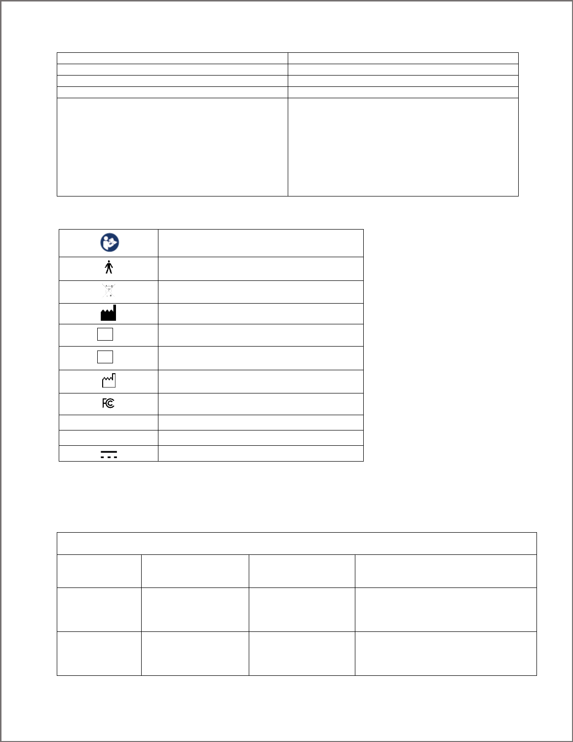
SYMBOL GLOSSARY
Refer to Instruction Manual / Booklet
Type B Applied Part
WEEE
Manufacturer
Catalog Number
Lot Number
Date of Manufacture
Federal Communications Commission
IP00
No protection against ingress of solid and liquid
Intertek?
Certification?
Direct Current
REAL Immersive System is a Type B Applied Part.
TECHNICAL INFORMATION
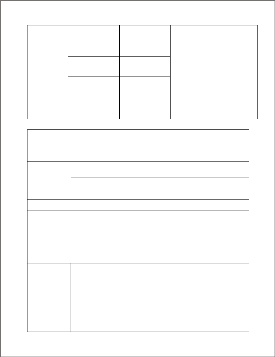
REAL Immersive System is intended for use in the electromagnetic environment specified below. The customer or the user of
REAL Immersive System should assure that it is used in such an environment.
Immunity test
IEC 60601
test level
Compliance level
Electromagnetic environment –
guidance
Electrostatic
discharge (ESD)
IEC 61000-4-2
±8 kV contact
±15 kV air
±8 kV contact
±15 kV air
Floors should be wood, concrete or
ceramic tile. If floors are covered with
synthetic material, the relative humidity
should be at least 30 %.
Electrical fast
transient/burst
IEC 61000-4-4
±2 kV for power
supply lines
±1 kV for input/output
lines
±2 kV for power
supply lines
±1 kV for input/output
lines
Mains power quality should be that of a typical
commercial or hospital
environment.
REF
LOT
IFU-133661 Revision 01 draft
Surge
IEC 61000-4-5
±1 kV differential
mode
±2 kV common mode
±1 kV differential
mode
±2 kV common mode
Mains power quality should be that of a typical
commercial or hospital
environment.
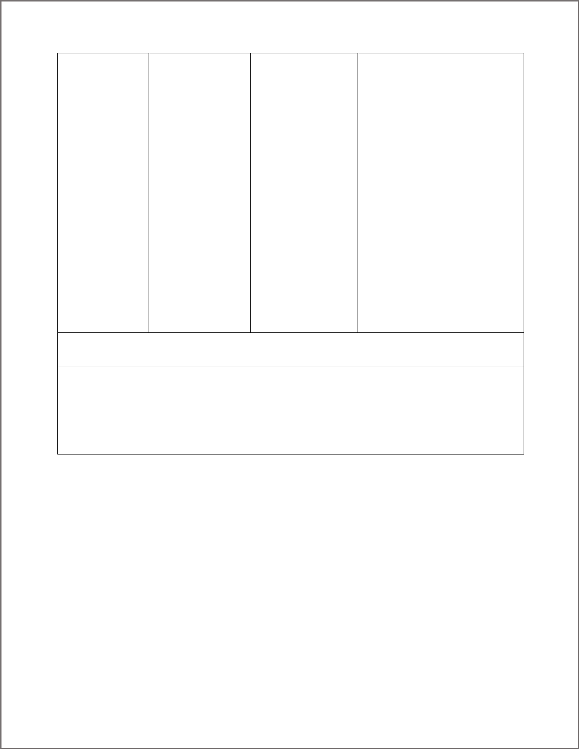
Voltage dips, short
interruptions and
voltage variations
on power supply
input lines
IEC 61000-4-11
Voltage Dips 30%
reduction, 25/30 periods
At 0°
Voltage Dips 30%
reduction, 25/30 periods
At 0°
Mains power quality should be that of a typical
commercial or hospital
environment. If the user of the
EQUIPMENT requires
continued operation during power
mains interruptions, it is recommended that
REAL Immersive System be powered from an
uninterruptible power
supply or a battery.
Voltage Dips > 95%
reduction, 0.5 period
At 0°, 45°, 90°, 135°,
180°, 225°, 270° and 315°
Voltage Dips > 95%
reduction, 0.5 period
At 0°, 45°, 90°, 135°,
180°, 225°, 270° and 315°
Voltage Dips > 95%
reduction, 1 period At 0°
Voltage Dips > 95%
reduction, 1 period At 0°
Voltage Interruptions >
95% reduction, 250/300
periods
Voltage Interruptions >
95% reduction, 250/300
periods
(50/60 Hz)
magnetic field
IEC 61000-4-8
30 A/m
30 A/m
Power frequency magnetic fields should be at
levels characteristic of a typical location in a
typical commercial or hospital environment.
Recommended separation distances between
portable and mobile RF communications equipment and REAL Immersive System
REAL Immersive System is intended for use in an electromagnetic environment in which radiated RF disturbances are
controlled. The customer or the user of REAL Immersive System can help prevent electromagnetic interference by
maintaining a minimum distance between portable and mobile RF communications equipment (transmitters) and REAL
Immersive System as recommended below, according to the maximum output power of the communications equipment.
Rated maximum
output power
of transmitter
W
Separation distance according to frequency of transmitter
m
150 kHz to 80 MHz
d = 1.2P
80 MHz to 800 MHz
d = 1.2P
800 MHz to 2.7 GHz
d = 2.3P
0.01
0.12
0.12
0.23
0.1
0.38
0.38
0.73
1
1.2
1.2
2.3
10
3.8
3.8
7.3
100
12
12
23
For transmitters rated at a maximum output power not listed above, the recommended separation distance d in meters (m)
can be estimated using the equation applicable to the frequency of the transmitter, where P is the maximum output power
rating of the transmitter in watts (W) according to the transmitter manufacturer.
NOTE 1 At 80 MHz and 800 MHz, the separation distance for the higher frequency range applies.
NOTE 2 These guidelines may not apply in all situations. Electromagnetic propagation is affected by absorption and
reflection from structures, objects and people.
REAL Immersive System is intended for use in the electromagnetic environment specified below. The customer or the user of
REAL Immersive System should assure that it is used in such an environment.
Immunity test
IEC 60601
test level
Compliance level
Electromagnetic environment –
guidance
Portable and mobile RF communications
equipment should be used no closer to
any part of REAL Immersive System,
including cables, than the recommended
separation distance calculated from the
equation applicable to the frequency of
the transmitter.
Recommended separation distance
IFU-133661 Revision 01 draft
Conducted RF
IEC 61000-4-6
Radiated RF
IEC 61000-4-3
3 Vrms
150 kHz to 80 MHz
(6 Vrms in ISM radio
Bands within 150kHz –
80MHz)
3 V/m
80 MHz to 2.7 GHz
3 Vrms
3 V/m
d = 1.2P
d = 1.2P 80 MHz to 800 MHz
d = 2.3P 800 MHz to 2.7 GHz
where P is the maximum output power
rating of the transmitter in watts (W)
according to the transmitter manufacturer
and d is the recommended separation
distance in metres (m).
Field strengths from fixed RF transmitters,
as determined by an electromagnetic site
surveya, should be less than the
compliance level in each frequency
range.b
NOTE 1 At 80 MHz and 800 MHz, the higher frequency range applies.
NOTE 2 These guidelines may not apply in all situations. Electromagnetic propagation is affected by absorption
and reflection from structures, objects and people.
a Field strengths from fixed transmitters, such as base stations for radio (cellular/cordless) telephones and land
mobile radios, amateur radio, AM and FM radio broadcast and TV broadcast cannot be predicted theoretically
with accuracy. To assess the electromagnetic environment due to fixed RF transmitters, an electromagnetic site
survey should be considered. If the measured field strength in the location in which REAL Immersive System is used exceeds
the applicable RF compliance level above, REAL Immersive System should be observed to verify normal operation. If
abnormal performance is observed, additional measures may be necessary, such as reorienting or relocating REAL
Immersive System.
b Over the frequency range 150 kHz to 80 MHz, field strengths should be less than 3 V/m.

IFU-133661 Revision 01 draft
Immunity to RF Wireless Communications Equipment
Test
Frequency
(MHz)
Band a)
(MHz)
Service a)
Modulation b)
Maximum
Power
(W)
Distance
(m)
IMMUNITY
TEST LEVEL
(V/m)
385
380 –390
TETRA 400
Pulse
modulation b)
18 Hz
1.8
0.3
27
450
430 – 470
GMRS 460,
FRS 460
FM c)
± 5 kHz deviation
1 kHz sine
2
0.3
28
710
704 – 787
LTE Band 13, 17
Pulse
modulation b)
217 Hz
0.2
0.3
9
745
780
810
800 – 960
GSM 800/900,
TETRA 800,
iDEN 820,
CDMA 850,
LTE Band 5
Pulse
modulation b)
18 Hz
2
0.3
28
870
930
1720
1 700 –
1 990
GSM 1800;
CDMA 1900;
GSM 1900;
DECT;
LTE Band 1, 3,
4, 25; UMTS
Pulse
modulation b)
217 Hz
2
0.3
28
1845
1970
2450
2 400 –
2 570
Bluetooth,
WLAN,
802.11 b/g/n,
RFID 2450,
LTE Band 7
Pulse
modulation b)
217 Hz
2
0.3
28
5240
5 100 –
5 800
WLAN 802.11
a/n
Pulse
modulation b)
217 Hz
0.2
0.3
9
5500
5785
a) For some services, only the uplink frequencies are included.
b) The carrier shall be modulated using a 50 % duty cycle square wave signal.
c) As an alternative to FM modulation, 50 % pulse modulation at 18 Hz may be used because while it does not represent actual
modulation, it would be worst case.
This device complies with part 15 of the FCC Rules. Operation is subject to the following two conditions: (1) This device may not
cause harmful interference, and (2) this device must accept any interference received, including interference that may cause
undesired operation.
This device contains licence-exempt transmitter(s)/receiver(s) that comply with Innovation, Science and Economic
Development Canada’s licence-exempt RSS(s). Operation is subject to the following two conditions:
1. This device may not cause interference.
2. This device must accept any interference, including interference that may cause undesired operation of the device.
IFU-133661 Revision 01 draft
L’émetteur/récepteur exempt de licence contenu dans le présent appareil est conforme aux CNR d’Innovation, Sciences et
Développement économique Canada applicables aux appareils radio exempts de licence. L’exploitation est autorisée aux deux
conditions suivantes :
1. L’appareil ne doit pas produire de brouillage;
2. L’appareil doit accepter tout brouillage radioélectrique subi, même si le brouillage est susceptible d’en
compromettre le fonctionnement.
Changes or modifications not expressly approved by the party responsible for compliance could void the user's authority to
operate the equipment.
Les changements ou les modifications qui n’ont pas été expressément approuvés par la partie responsable de la conformité
peuvent faire perdre à l’utilisateur son droit d’utiliser l’appareil.
This equipment has been tested and found to comply with the limits for a Class A digital device, pursuant to part 15 of the FCC
Rules. These limits are designed to provide reasonable protection against harmful interference when the equipment is operated
in a commercial environment. This equipment generates, uses, and can radiate radio frequency energy and, if not installed and
used in accordance with the instruction manual, may cause harmful interference to radio communications. Operation of this
equipment in a residential area is likely to cause harmful interference in which case the user will be required to correct the
interference at his own expense.
Mode of Operation:
Charging mode and battery mode
Highest Clock Frequency:
Dongle: 16MHz
WSM: 24.576MHz
WTM: 24.576MHz
Frequency Range:
2402MHz - 2479MHz
Transmitting Frequency and Modulation:
Frequency-shift Keying (FSK) modulation. 2Mbit modulation for all transmitter frequencies.
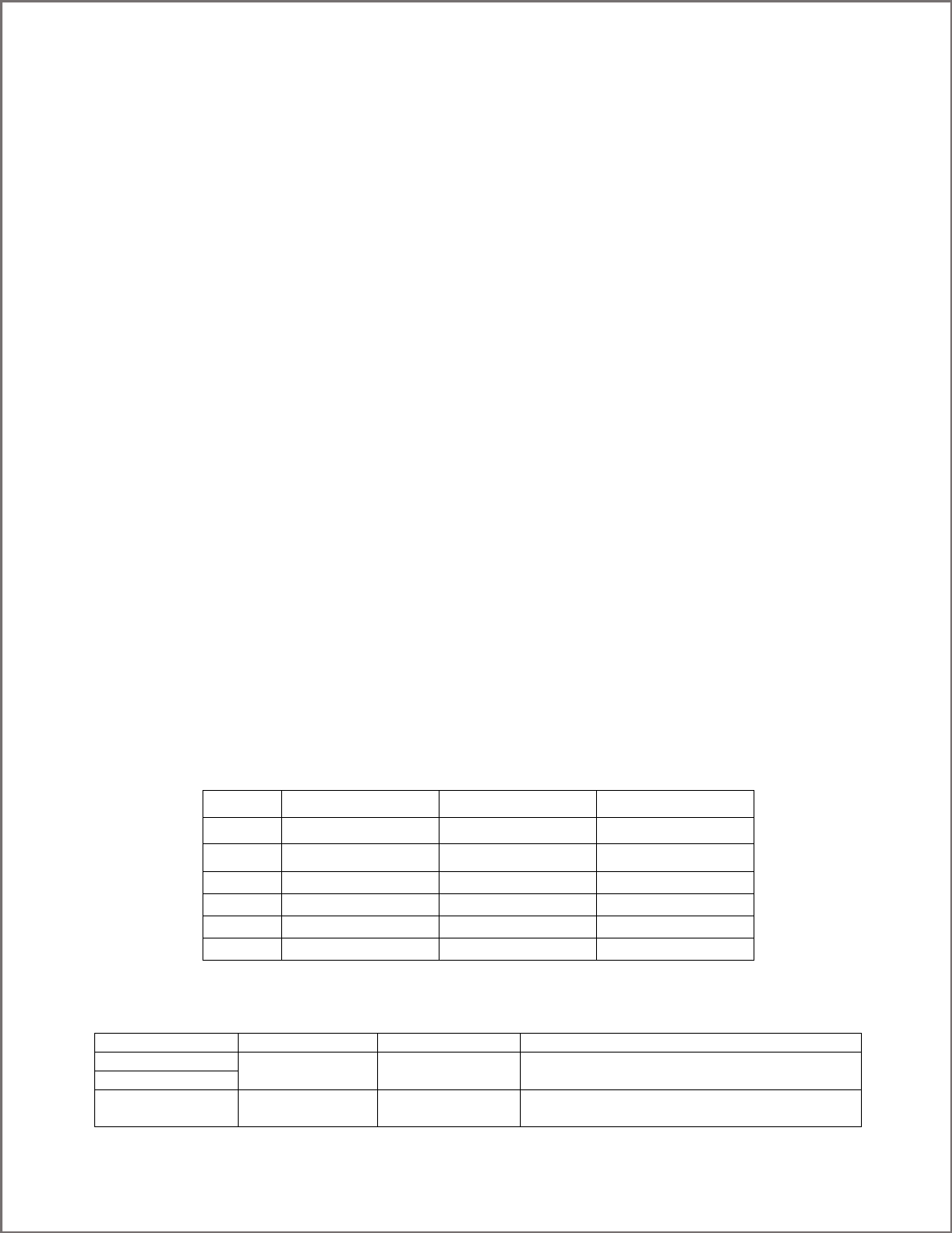
Operating Channels:
6 Channels per the following table.
Channel
F1
F2
F3
20
2402 MHz
2439 MHz
2469 MHz
21
2405 MHz
2444 MHz
2474 MHz
22
2410 MHz
2449 MHz
2479 MHz
23
2415 MHz
2454 MHz
2428 MHz
24
2420 MHz
2459 MHz
2431 MHz
25
2425 MHz
2464 MHz
2436 MHz
Antenna Make, Model, and Gain:
Device
Antenna Make
Antenna Model
Antenna Gain
WSM
Johanson
P/N 2450AT43B100E
Peak Gain 1.3 dBi
Average Gain -0.5 dBi
WTM
RF Dongle
NORDIC
nRF52
Peak Gain -2 dBi
Average Gain -3.7 dBi

IFU-133661 Revision 01 draft
Power Output and Data Rate:
Device
Power Output
Data Rate
WSM
Transmitter with programmable output power of +4
dBm to -20 dBm, in 4 dB steps. Programmed by the
firmware to +0dBm.
GFSK modulation, 2 Mbps data rate.
WTM
RF Dongle
Transmitter with programmable output power of 0 to -
18 dBm, in 6 dB steps.