PeopleNet Communications DV423 Digital Video Recorder User Manual Video Intelligence Owners Manual
PeopleNet Communications Corporation Digital Video Recorder Video Intelligence Owners Manual
UserManual.wiki
>
PeopleNet Communications
>
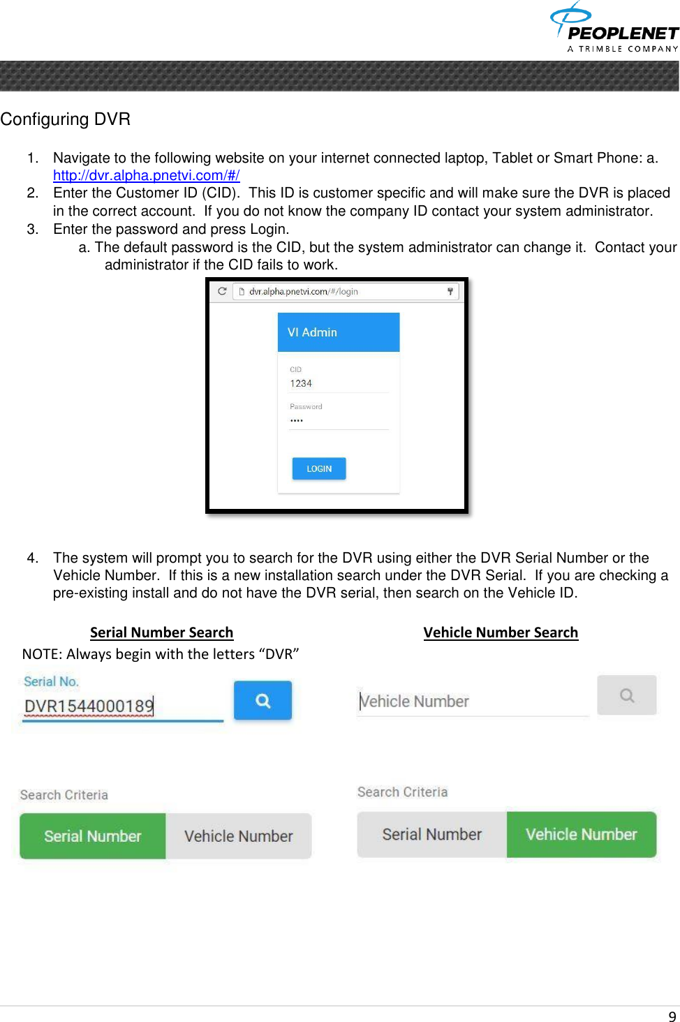
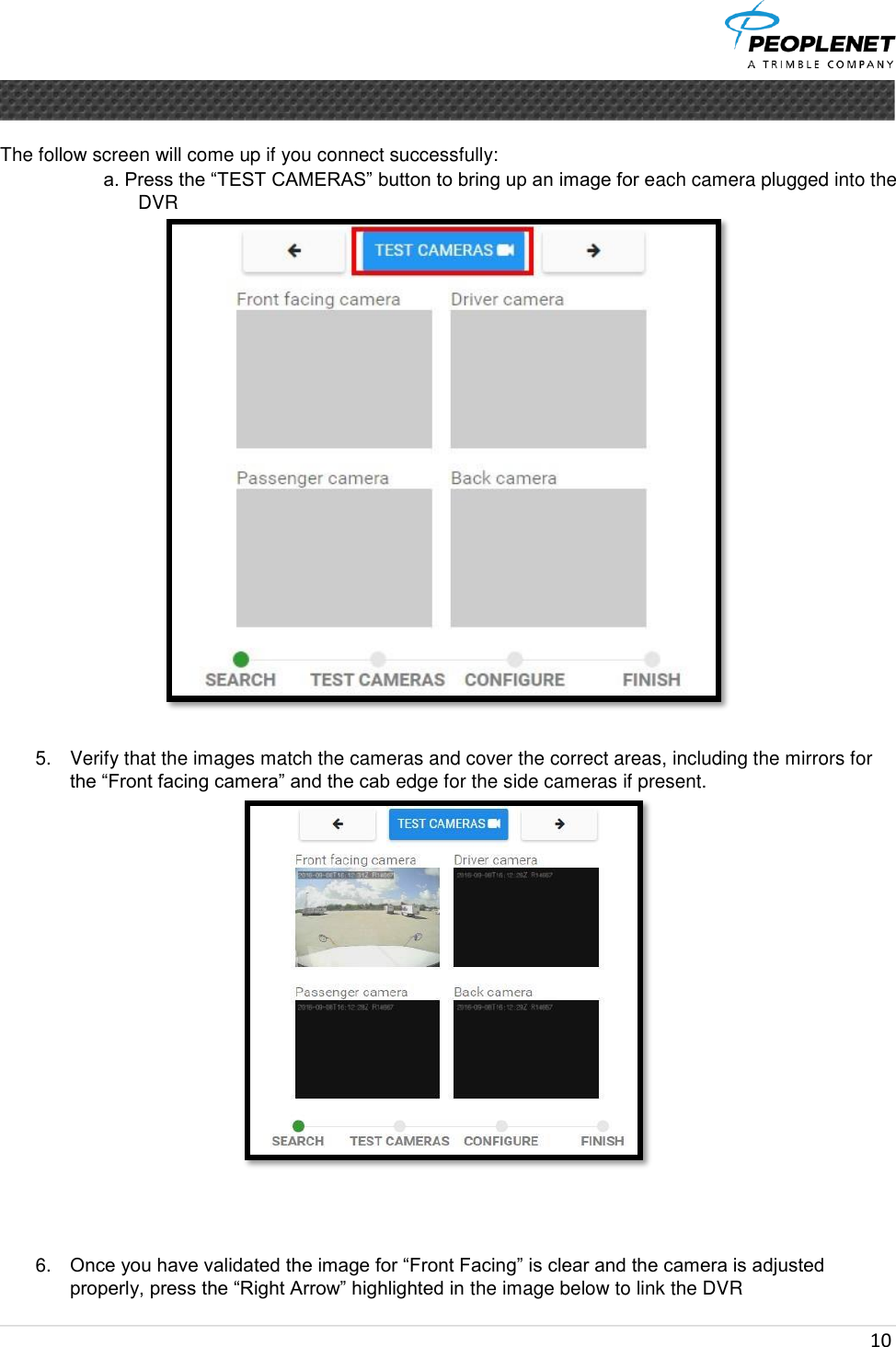
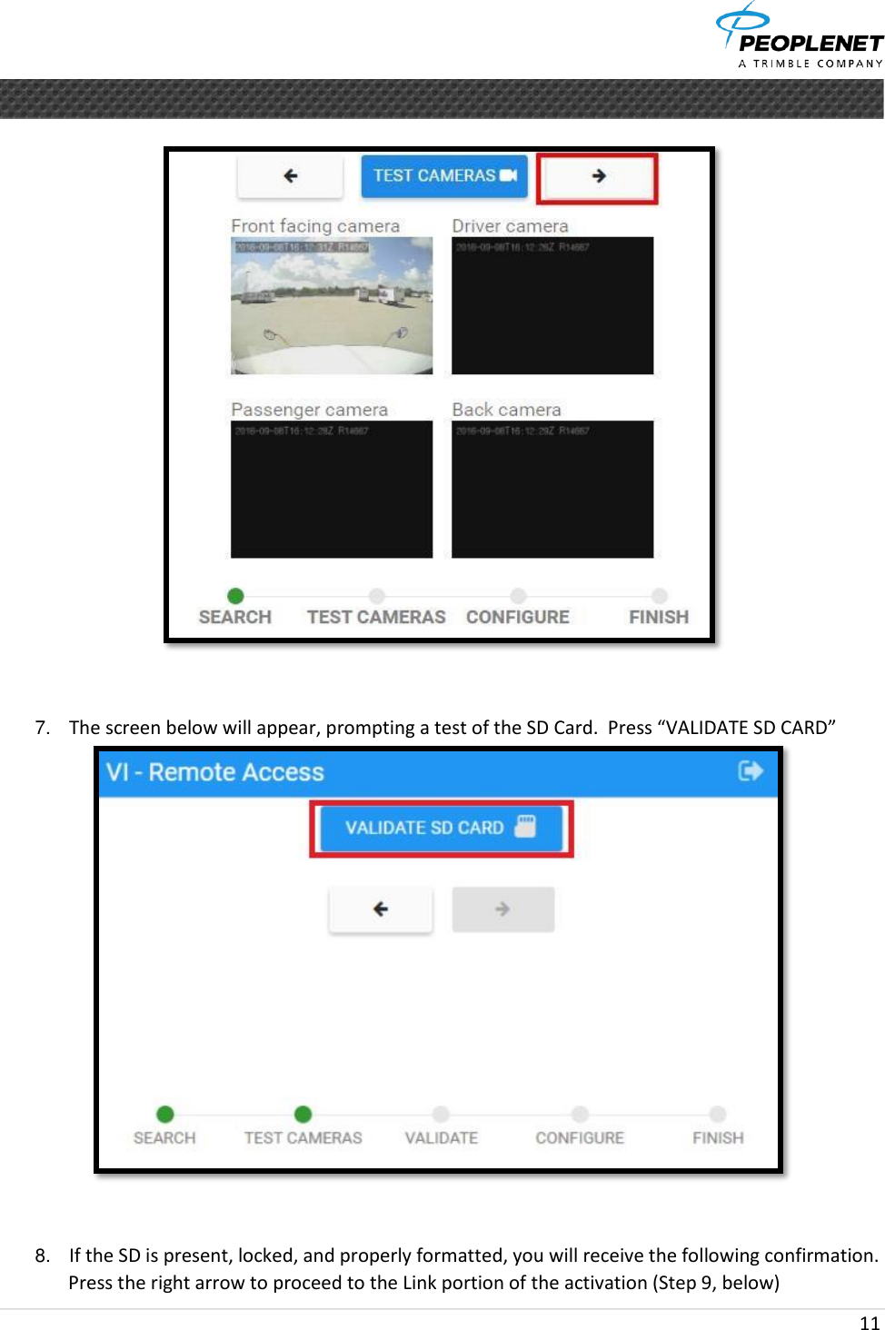
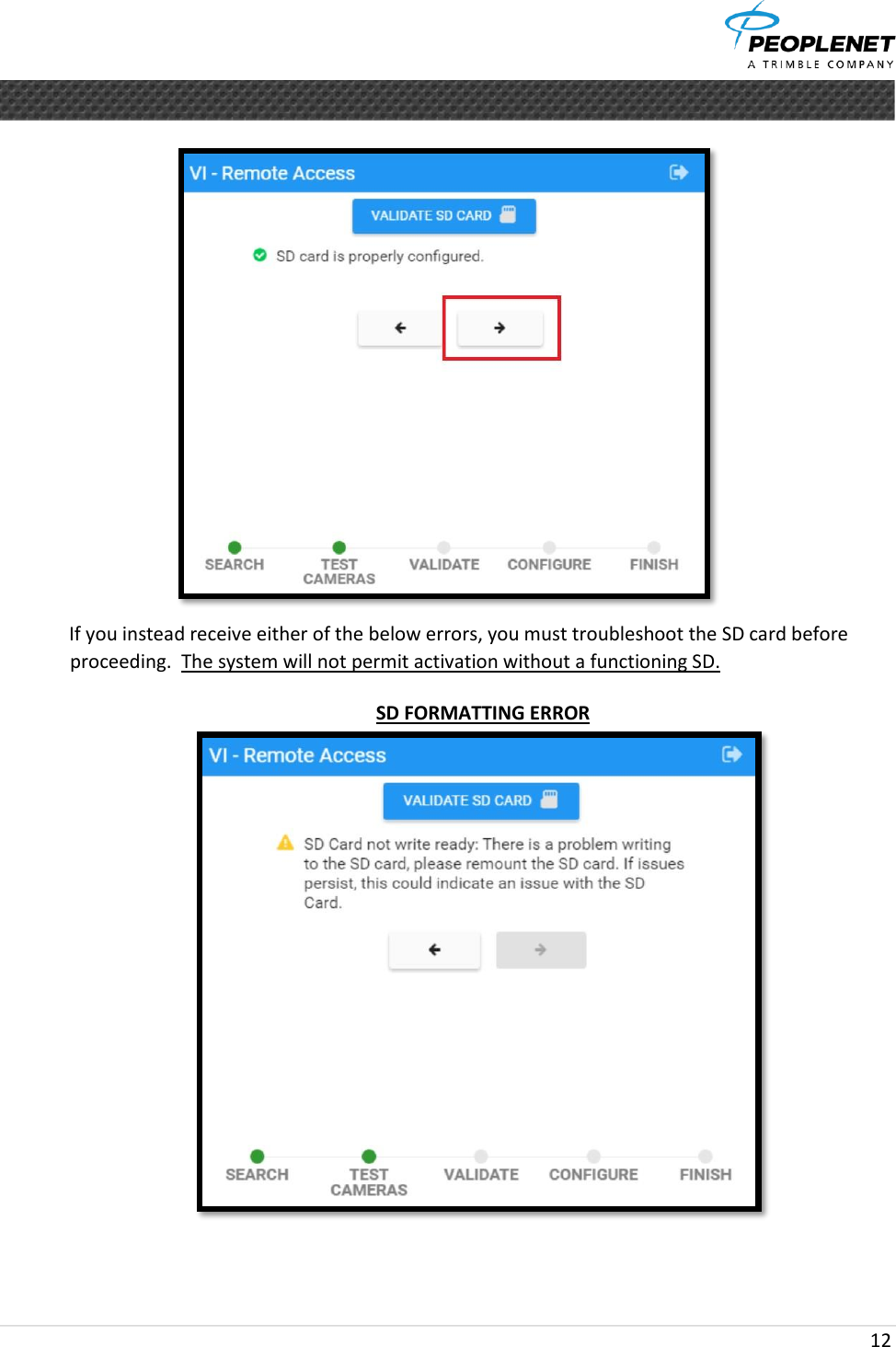
DV423 User Manual
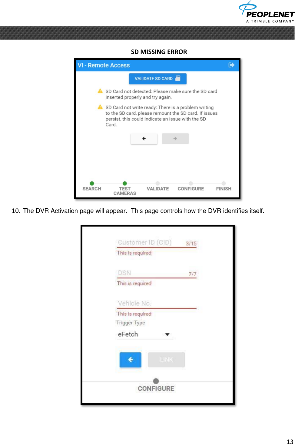
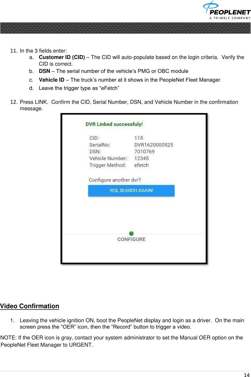
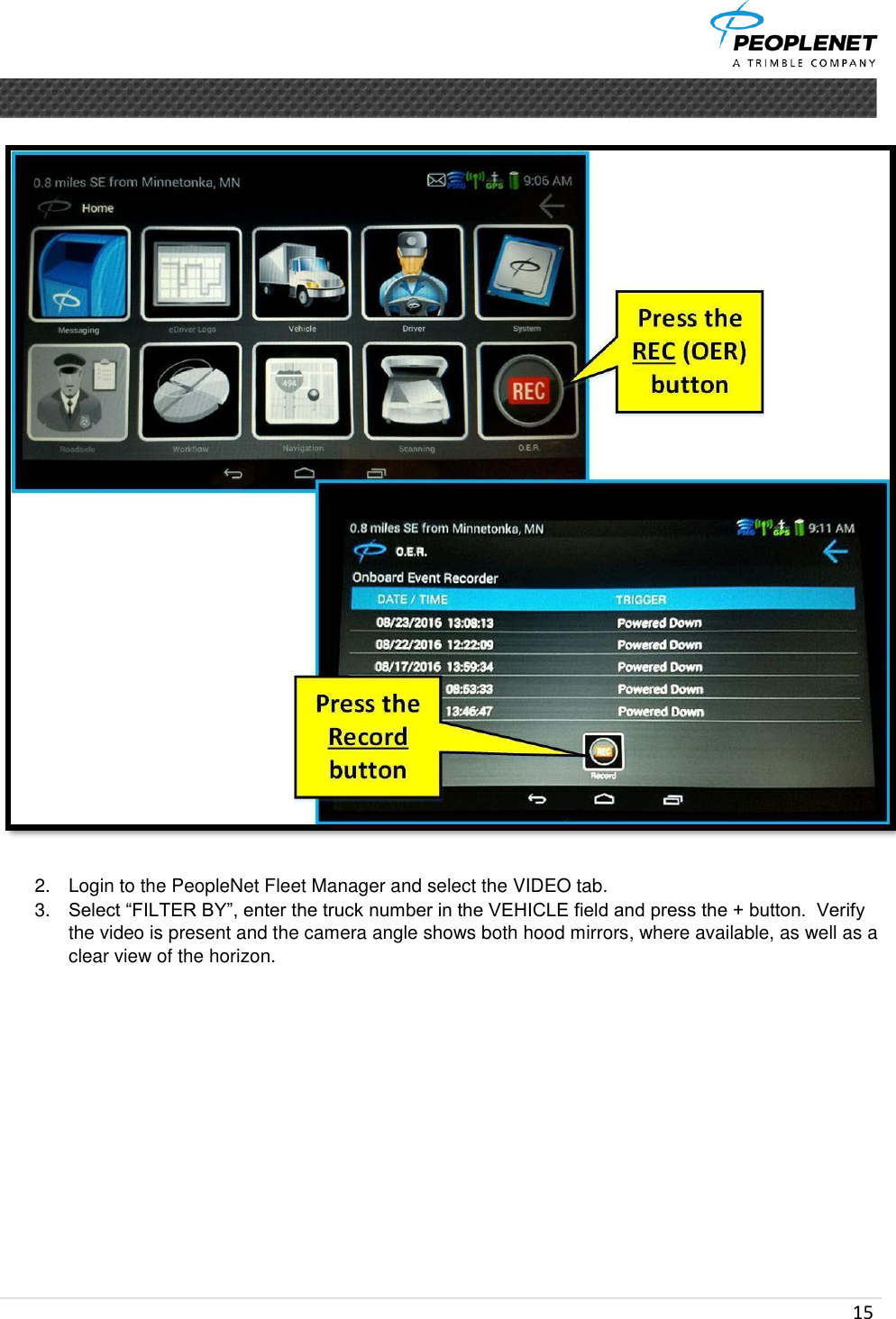
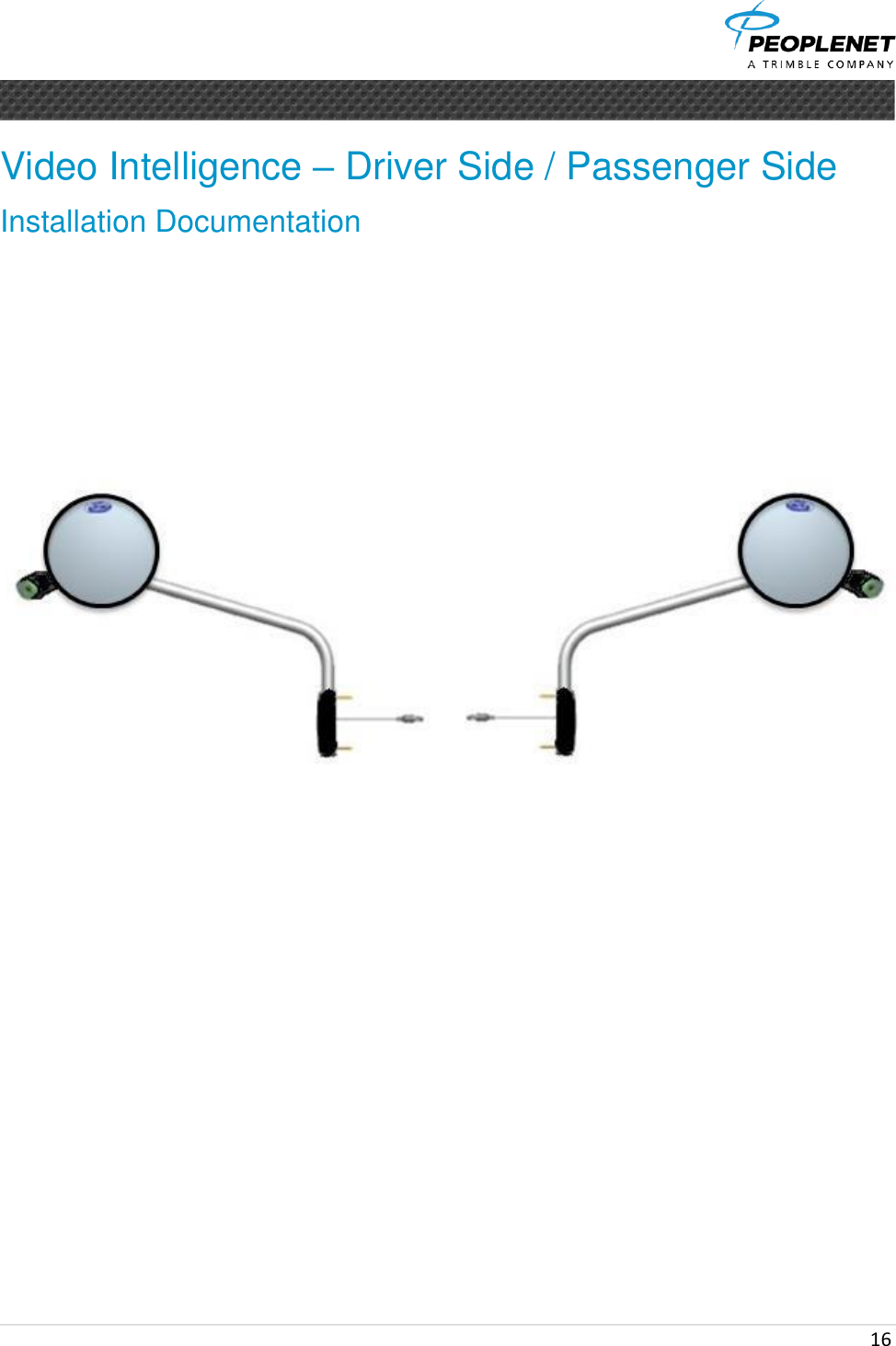
Video Intelligence Owners Manual
Navigation menu
Upload a User Manual
Namespaces
Wiki Guide
HTML
PDF
Info
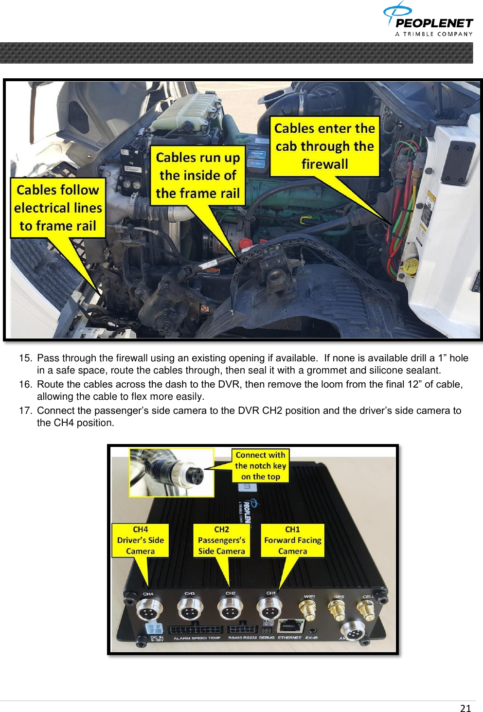
Views
User Manual
Discussion / Help
Navigation