Pepperl Fuchs IQT118GMIO RFID Reader User Manual tdoct5706A eng
Pepperl + Fuchs Inc RFID Reader tdoct5706A eng
user manual
MANUAL
IO
-
Link RFID Reader, HF
13.56 MHz, ISO 15693
IQT1-18GM-IO-V1
IQT1-F61-IO-V1
IQT1-FP-IO-V1
FACTORY AUTOMATION

2017
-07
2
IO
-
Link RFID Reader, HF
The latest version of the
General Terms of Delivery for Products and Services of the
Electrical Industry set out by the German Electrical and Electronic Manufacturers'
Association (ZVEI), and the "Extended Retention of Title" clause apply to this document.

2017
-07
3
IO
-
Link RFID Reader, HF
1
Introduction .......................................................................................................................................... 4
2
Declaration of Conformity ..................................................................................................................... 5
2.1
Declaration of Conformity .............................................................................................................. 5
2.2
FCC and IC Information................................................................................................................. 5
3
Safety .................................................................................................................................................. 6
3.1
Safety-Relevant Symbols .............................................................................................................. 6
3.2
Intended Use ................................................................................................................................ 6
3.3
General Safety Information............................................................................................................ 6
3.4
Special Safety Instructions ............................................................................................................ 7
3.4.1
IQT1-*-IO-V1......................................................................................................................... 7
3.4.2
IQT1-18GM-IO-V1................................................................................................................. 7
4
Product Description .............................................................................................................................. 8
4.1
Indicators and Operating Elements................................................................................................ 8
4.2
Connection ................................................................................................................................... 9
4.3
Accessories .................................................................................................................................. 9
5
Installation ...........................................................................................................................................10
5.1
Storage and Transportation ..........................................................................................................10
5.2
Unpacking ...................................................................................................................................10
5.3
Mounting and Connecting the Read/Write Head ...........................................................................10
6
Operation ............................................................................................................................................11
6.1
General Information about Tag Types...........................................................................................11
6.2
IO-Link ........................................................................................................................................12
6.3
IO-Link Easy Mode ......................................................................................................................12
6.3.1
Command Overview.............................................................................................................12
6.3.2
Data Structure of Easy Mode ................................................................................................12
6.3.3
Timing..................................................................................................................................15
6.3.4
Application Example: Easy Mode with PACTware .................................................................15

2017
-07
4
IO
-
Link RFID Reader, HF
1 Introduction
Congratulations
You have decided to purchase a device from Pepperl+Fuchs. Pepperl+Fuchs develops,
produces, and markets electronic sensors and interface modules worldwide for the
automation technology market.
Please read the instruction manual carefully before installing this device and putting it into
operation. The instructions and notes contained in this instruction manual will guide you step
by step through the installation and commissioning procedures to ensure fault-free use of this
product. By following the instructions in this manual, you:
ensure safe operation of the device.
can utilize the entire range of device functions.
avoid faulty operation and associated errors.
reduce costs associated with downtime and incidental repairs.
increase the effectiveness and economic efficiency of your plant.
Store this instruction manual somewhere safe to ensure it is available for future work on the
device.
After opening the packaging, please ensure that the device is intact and that the package is
complete.
Symbols Used
The following symbols are used in this manual:
Important note!
You will find important information beside this symbol.
Handling instructions
Handling instructions are provided next to this symbol.
Contact
If you have any questions about the device, its functions, or accessories, please contact us at:
Pepperl+Fuchs GmbH
Lilienthalstrasse 200
68307 Mannheim, Germany
Tel.: +49 (0)621 776-1111
Fax: +49 (0)621 776-271111
Email: fa-info@de.pepperl-fuchs.com
2017
-07
5
IO
-
Link RFID Reader, HF
2 Declaration of Conformity
2.1 Declaration of Conformity
This product was developed and manufactured in line with the applicable European standards
and Directives.
Important note!
A Declaration of Conformity may be requested from the manufacturer.
The product manufacturer, Pepperl+Fuchs GmbH, 68307 Mannheim, Germany, has a
certified quality assurance system that conforms to ISO 9001.
2.2 FCC and IC Information
NOTICE:
This device complies with Part 15 of the FCC Rules and with Industry Canada license-exempt
RSS standard(s).
Operation is subject to the following two conditions:
(1) this device may not cause harmful interference, and
(2) this device must accept any interference received, including interference that may
cause undesired operation.
Le présent appareil est conforme aux CNR d'Industrie Canada applicables aux appareils
radio exempts de licence. L'exploitation est autorisée aux deux conditions suivantes:
(1) l'appareil ne doit pas produire de brouillage, et
(2) l'appareil doit accepter tout brouillage radioélectrique subi, même si le brouillage est
susceptible d'en compromettre le fonctionnement.
Notice
Changes or modifications made to this equipment not expressly approved by the
manufacturer may void the FCC authorization to operate this equipment.
Important note!
This equipment has been tested and found to comply with the limits for a Class A digital
device, pursuant to Part 15 of the FCC Rules. These limits are designed to provide
reasonable protection against harmful interference when the equipment is operated in a
commercial environment. This equipment generates, uses, and can radiate radio frequency
energy and, if not installed and used in accordance with the instruction manual, may cause
harmful interference to radio communications. Operation of this equipment in a residential
area is likely to cause harmful interference in which case the user will be required to correct
the interference at his own expense.
2017
-07
6
IO
-
Link RFID Reader, HF
3 Safety
3.1 Safety-Relevant Symbols
Danger!
This symbol warns of an immediate and present danger.
Failure to observe this warning may result in personal injury or even death.
Warning!
This symbol warns of a potential fault or hazard.
Failure to observe this warning may result in personal injury or extensive damage to property.
Caution
!
This symbol warns of a potential fault.
Failure to observe this warning may result in the device and/or any systems and plants
connected to it malfunctioning or failing completely.
3.2 Intended Use
The read/write head is designed to identify RFID read-only and read/write tags within a
defined frequency range and should only be used for this purpose.
Read through this manual carefully. Familiarize yourself with the device before installing,
mounting, and operating it.
Always operate the device as described in these instructions to ensure that the device and the
connected systems function correctly. The protection of operating personnel and of the plant
is only guaranteed if the device is operated in accordance with its intended use.
3.3 General Safety Information
The device must only be operated by specialist personnel who have received the relevant
training in accordance with this instruction manual.
If you open or modify the device yourself, not only are you endangering yourself and others
but you will also void any warranty and absolve the manufacturer of any liability. Switch off the
device if serious faults occur. Make sure that the device cannot be inadvertently switched on
again. If the device needs to be repaired, return it to Pepperl+Fuchs.
The device may only be connected by a qualified electrical specialist. The same applies for
any maintenance work that needs to be carried out when the system is live.
The operator is responsible for complying with all local safety regulations.
Store the device in the original packaging when not in use. This offers the device optimal
protection against impact and moisture.
2017
-07
7
IO
-
Link RFID Reader, HF
Ensure that the ambient conditions comply with regulations.
Important note!
Disposal
Electronic waste is hazardous waste. When disposing of the equipment, observe the current
statutory requirements in the respective country of use, as well as local regulations.
3.4 Special Safety Instructions
3.4.1 IQT1-*-IO-V1
Warning!
Processes started in an uncontrolled manner jeopardize the plant.
Before commissioning, ensure that there are no risks involved in using the device that may
endanger the plant.
Power Supply
The read/write head is supplied with power via the IO-Link master. For technical details, refer
to the product datasheet.
3.4.2 IQT1-18GM-IO-V1
Warning!
Hot parts!
Be careful not to burn your fingers when handling the device! After shutting down the device,
wait at least half an hour before handling it.
2017
-07
8
IO
-
Link RFID Reader, HF
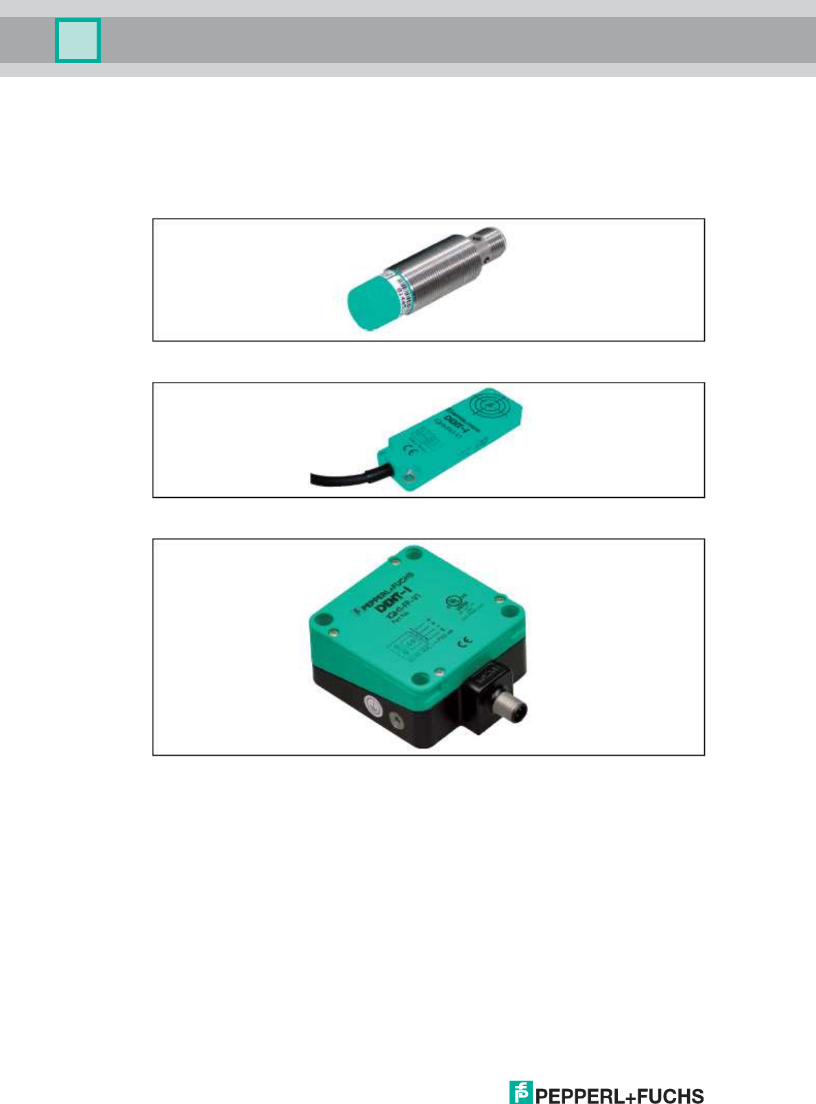
4 Product Description
These products have RFID read/write heads with an IO-Link interface. The read/write heads
write and read read/write tags within a frequency range of 13.56 MHz according to ISO 15693.
The devices are connected via M12 plugs.
Figure 4.1 IQT1-18GM-IO-V1
Figure 4.2 IQT1-F61-IO-V1
Figure 4.3 IQT1-FP-IO-V1
4.1 Indicators and Operating Elements
The IQH1-*-IO-V1 read/write heads have four LEDs in green/blue/yellow/red. The various
indicators denote:
Green LED:
Permanently on - Power on
Flashing - IO-Link communication active
Blue LED: Transmission mode
Yellow LED: Read/write operation successful
Red LED: Fault
2017
-07
9
IO
-
Link RFID Reader, HF
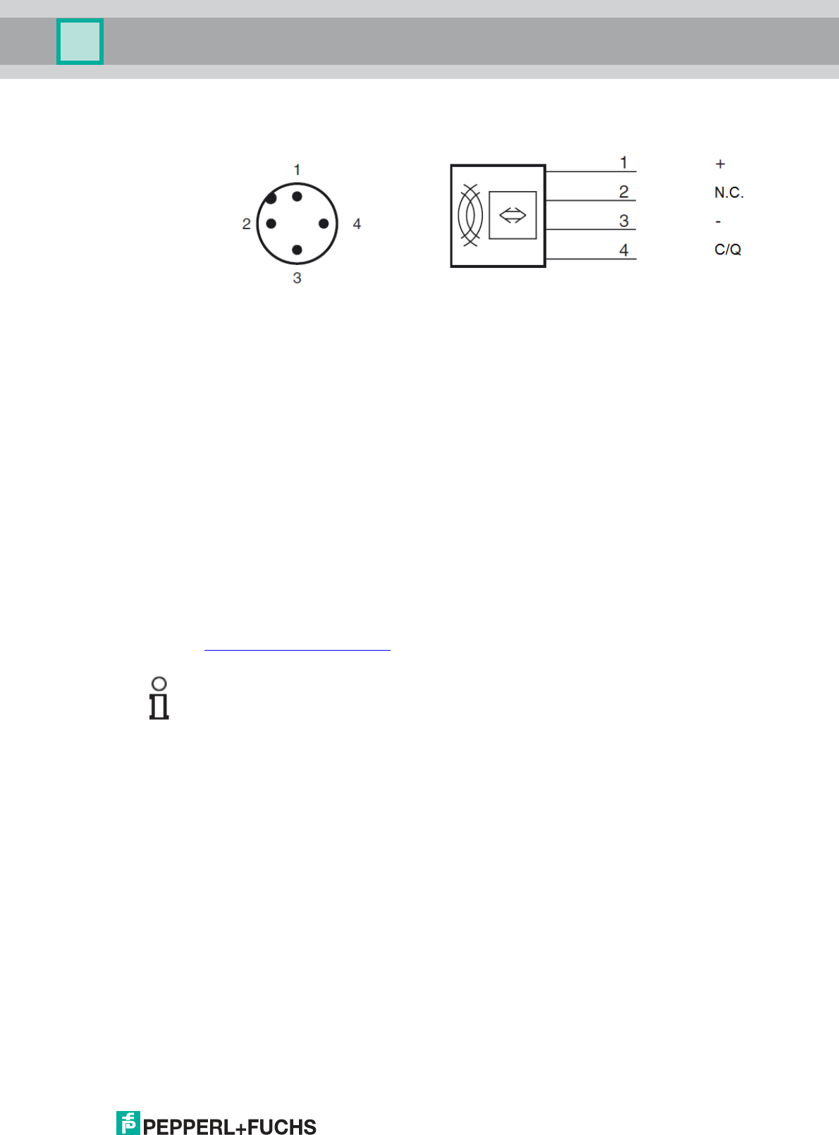
4.2 Connection
Pin 2 is not used.
The read/write head is connected via a point-to-point connection to the IO-Link master.
According to the IO-Link standard, the connection line may be up to 20 meters long.
4.3 Accessories
You can connect the IQT1-*-IO-V1 read/write heads to any IO-Link master. The following IO-
Link masters are available from Pepperl+Fuchs:
IO-Link-Master02-USB IO-Link master for connection to higher-level devices via USB
ICE1-8IOL-G60L-V1D Ethernet IO-Link module with eight inputs/outputs for connection to
a higher-level system via Ethernet IP, Profinet, or EtherCat.
You can use any HF read/write tag that complies with ISO 15693.
An unshielded three- or four-wire cable with an M12 plug and a maximum length of 20 m can
be used to connect the read/write head to the IO-Link master.
You can find suitable accessories on our website
http://www.pepperl-fuchs.com
Important note!
In the product search, simply enter the type designation for your read/write head. The product
page contains a list of related products.
2017
-07
10
IO
-
Link RFID Reader, HF
5 Installation
5.1 Storage and Transportation
Package the device for storage and transportation such that it is protected from impact and
moisture. The original packaging provides optimum protection. Please also observe the
permitted ambient conditions found in the technical datasheet.
5.2 Unpacking
Check the product for damage while unpacking. In the event of damage to the product, inform
the post office or parcel service and notify the supplier.
Retain the original packaging in case you have to store or ship the device again at a later
point.
Should you have any questions, please contact Pepperl+Fuchs.
5.3 Mounting and Connecting the Read/Write Head
Important note!
The read/write head is intended for mounting indoors. Do not mount the read/write head on
metal surfaces. Maintain a minimum distance of 50 mm between the device and any
metals.
If you want to mount multiple devices side by side, keep a minimum distance of 210 mm
between them to avoid interference.
Ensure the device is mounted on a level surface.
Mounting and Connecting
1. Attach the IQT1-F61-IO-V1 read/write head using two screws or the IQT1-FP-IO-V1
using four screws by feeding the screws through the mounting holes in the housing.
Attach the IQT1-18GM-IO-V1 read/write head using suitable mounting materials, e.g.,
nuts or mounting aids.
2. Connect the device to an IO-Link master that communicates with a higher-level
system.
2017
-07
11
IO
-
Link RFID Reader, HF
6 Operation
6.1 General Information about Tag Types
Read/Write Tag 13.56 MHz (Inductive)
Read/write tags in this frequency range offer a considerably higher reading speed than
read/write tags for the 125 kHz system. Since this is a non-proprietary system, cost-effective
read/write tags are available from many third-party manufacturers.
By using a command, you can tell the device which specific read/write tag to communicate
with.
IQT1-*-IO-V1 read/write stations currently support the following read/write tags:
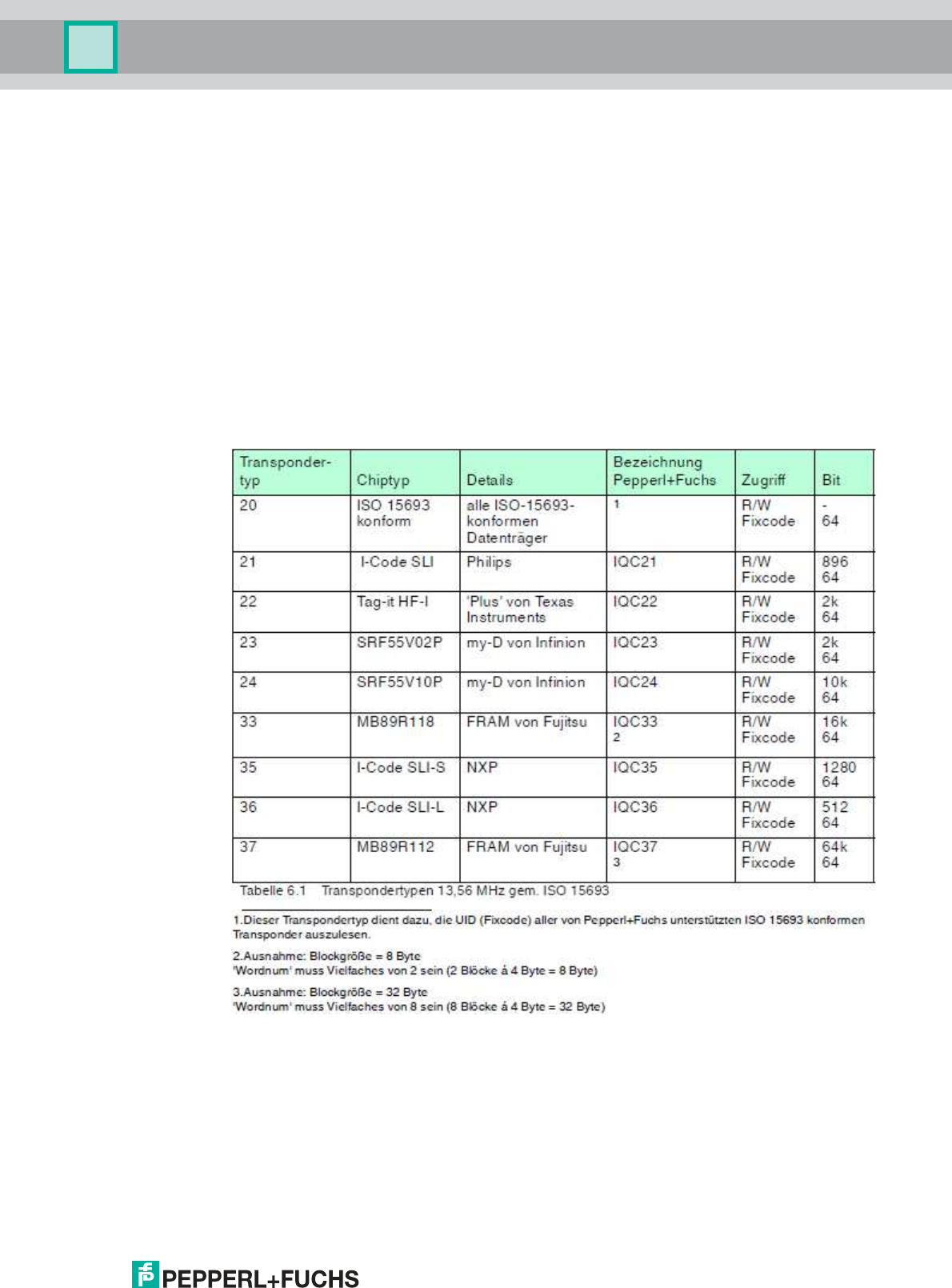
13.56 MHz/ISO 15693 Tag Types
The read/write tags usually have a 64 byte unique read-only code that has been defined by
the manufacturer and can only be read, but not changed, by the user. In addition, most
read/write tags have a memory bank (R/W user memory) that can be read and written. The
size of this memory bank depends on the tag type. The memory bank of most read/write tags
is divided into blocks that are 4 bytes in length. When a read/write command is issued, the
start address and the requested number of data blocks or number of bytes are indicated for
access purposes.

2017
-07
12
IO
-
Link RFID Reader, HF
6.2 IO-Link
The IQT1-*-IO-V1 read/write heads support IO-Link version 1.1. SIO mode is not supported.
The process data size is always 32 bytes in/out.
6.3 IO-Link Easy Mode
Easy mode enables the intuitive commissioning of the read/write head without a function
block. The data for easy mode is split into parameters that are acyclically transferred into
process data that is cyclically exchanged between the read/write head and the IO-Link
master.
You can adjust the parameters of the read/write head that are defined by the IODD file via a
configuration tool. The parameters are stored in the non-volatile memory of the reader until
the next change. The read/write commands are also part of the set of parameters and are not
transferred as cyclic process data. You can select the read/write command you want via the
configuration tool from a list of possible read/write commands.
6.3.1 Command Overview
Easy mode supports the following read/write commands:
• Read the read-only code (UID)
• Read the user memory
• Write the user memory
The start address and desired number of data blocks are required to read and write the user
memory. No further information is necessary to read the UID.
6.3.2 Data Structure of Easy Mode
Parameters
The following parameters are available for the read/write head.
Easy mode
This parameter defines which of the two modes of the read/write head is operated. At present,
only easy mode is implemented.
Value range: true, false
Default value: true
Tag type
This parameter tells the read/write head which tag type to communicate with. The settings are
stored in the non-volatile memory of the read/write head.
Value range: see Table 6.1
Default value: 99 (automatic)

2017
-07
13
IO
-
Link RFID Reader, HF
Choose read command
This parameter defines the read command that the write/read head will perform at the next
reading.
Value range: UID, user memory
Default value: UID
Choose write command
This parameter defines the write command that the read/write head will perform at the next
writing.
Value range: user memory
Default value: user memory
Number of bytes [user memory]
This parameter defines the number of bytes that the next command reads from the user
memory or writes to the user memory. The block length of the read/write tags being used and
the maximum available data range of 28 bytes per cycle should be observed. Read/write tag
type 37 cannot be used in easy mode as its block length of 32 bytes is larger than the
maximum available data range.
Value range: 4, 8, 12, 16, 20, 24, 28
Default value: 4
Format: decimal
Starting address [user memory]
This parameter defines the start address from which the next command data is read from the
user memory or written to the user memory. The block length of the read/write tag being used
and the maximum available data range of 28 bytes per cycle should be observed. Read/write
tag type 37 cannot be used in easy mode as its block length of 32 bytes is larger than the
maximum available data range.
Value range: depends on the size of the user memory and the block length
Default value: 0
Format: hexadecimal
Autostart
This parameter defines whether or not the read command is carried out immediately when
you turn on the read/write head without taking into account the control bits of the process data
of the output frames.
Value range: true, false
Default value: true
Process Data
The process data consists of an output frame and an input frame. The output frame contains
the data that is transferred cyclically from the IO-Link master to the reader. The input frame
contains the data that is transferred back from the reader to the IO-Link master.

2017
-07
14
IO
-
Link RFID Reader, HF
Output Frame
Byte
Contents
0
0
0
0
0
0
0
Write
Read
1
Occupied
2
Occupied
3
Occupied
4
Write data
…
Write
data
31
Write data
Byte 0 is composed of eight control bits. Six bits are currently unused.
Read: As long as the read bit value is set to true, the configured read command will
be executed. If the Autostart parameter is set to true, the read bit will not be
evaluated and the configured read command will always be executed.
Write: As long as the write bit value is set to true, the configured write command will
be executed. If the Autostart parameter is set to true, the write bit will not be
evaluated and the configured read command will always be executed.
Bytes 1, 2, and 3 are not used and are allocated zero, because some controls such as the
Rockwell Collins controls operate on four bytes.
Write data: Bytes 4 to 31 contain the data in hexadecimal form, which is written by the
read/write head to the read/write tag using the configured write command.
Input Frame
Byte
Contents
0
0
0
0
0
Failure
Run
W.valid
R.valid
1
Frame length
2
Occupied
3
Occupied
4
Read data/error code
5
Read data/error string
…
Read data/error string
31
Read data/error string
Byte 0 is composed of eight control bits. Four bits are currently unused.
Read valid: A rising edge indicates that new data has been read and is now available.
Write valid: A rising edge indicates that new data has been written.
Run: As long as the run bit value is set to true, a read or write command will be
executed.
Failure: If the failure bit value is set to true, there is an error.
2017
-07
15
IO
-
Link RFID Reader, HF
Frame length: Contains the number of valid bytes of data read in the input frame.
Bytes 2 and 3 are not used and are allocated zero, because some controls such as the
Rockwell Collins controls operate on four bytes.
Read data: Bytes 4 to 31 contain the data in hexadecimal form, which is read by the
read/write head from the read/write tag using the configured write command.
Error code: If an error occurs (failure = true), byte 4 contains an error code.
Error string: If an error occurs (failure = true), bytes 5 to 31 contain a human-readable
error message in ASCII format.
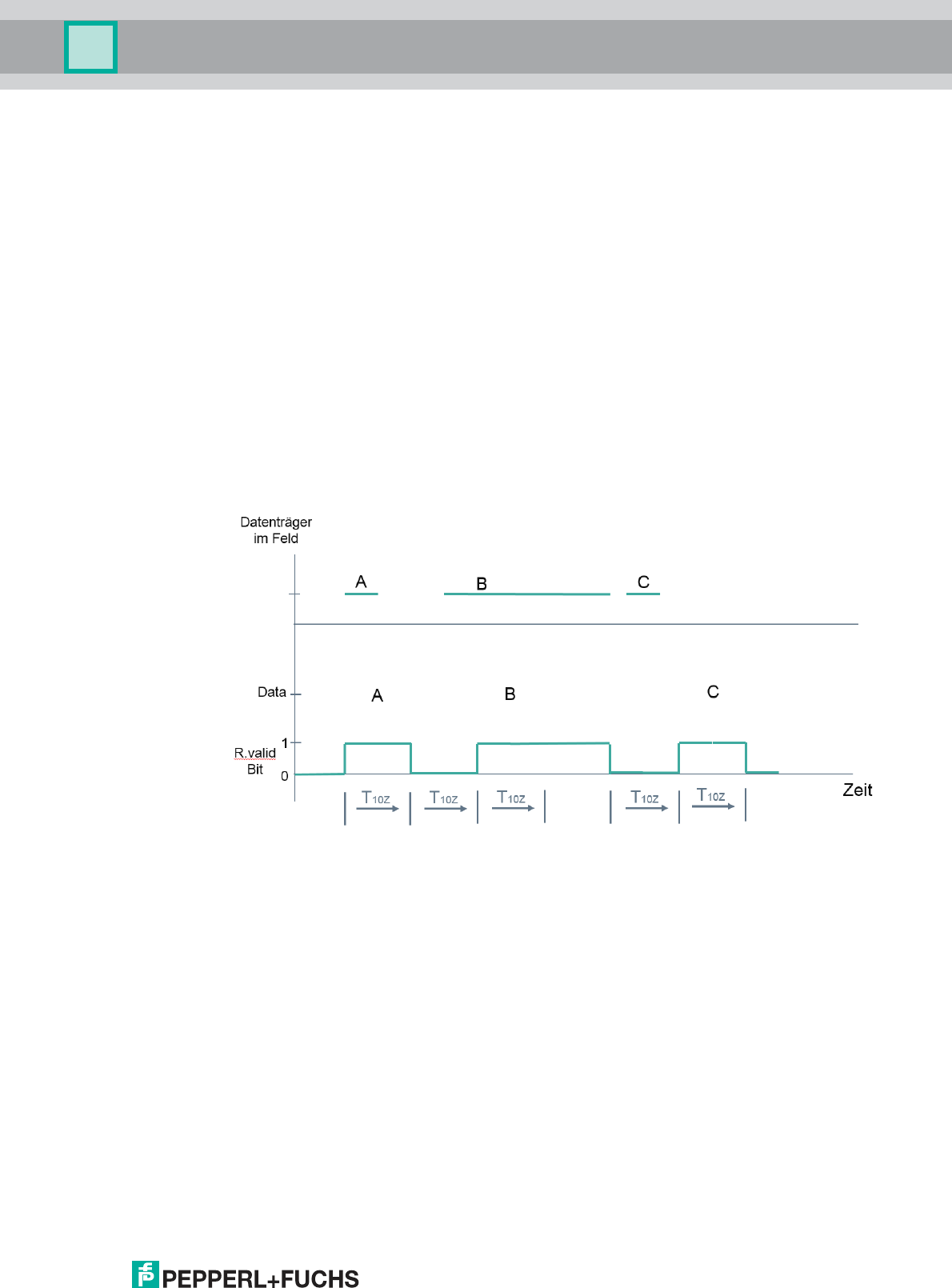
6.3.3 Timing
Easy mode does not support a handshake. Instead, a simple counter is implemented. The IO-
Link cycle time of the read/write head is 4 ms. The input frame is updated at least every ten
cycles. You cannot change the number of cycles for the update. Therefore, new process data
is available every 40 ms.
The image shows the basic, temporal reading behavior of the read/write head. The read bit in
the output frame is true, meaning that the read/write head reads permanently. If read/write tag
A now enters the detection range of the read/write head, the read valid bit changes from 0 to
1. Because the read/write tag leaves the detection range straight away, the read valid bit
changes after 10 cycles, i.e., after 40 ms, from 1 back to 0. Read/write tag B now enters the
detection range of the read/write head. Accordingly, its UID is read and after a further 40 ms is
available in the input frame. Since the read/write tag remains in the detection range for longer,
the read valid bit is still at 1 after 40 ms, since no change has occurred. Once read/write tag B
has left the detection range, the read valid bit changes from 1 back to 0. Read/write tag C is in
the detection range for only a very brief time. After a further 40 ms, its data becomes available
in the input frame.
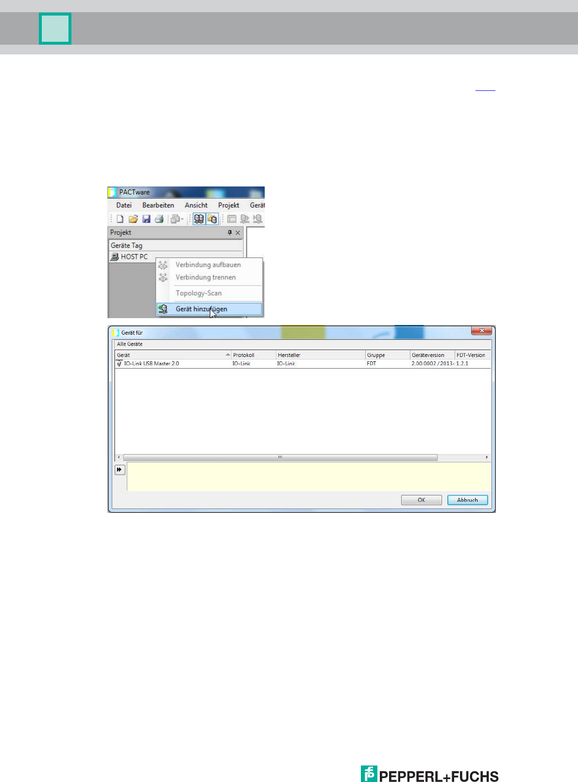
6.3.4 Application Example: Easy Mode with PACTware
In this section, you will learn how to use the read/write head with IO-Link Master02-USB.
Connect the read/write head to the IO-Link master and then connect it to a PC using a USB
2017
-07
16
IO
-
Link RFID Reader, HF
cable. The PACTware software is used to operate the system and can be downloaded here
from the Pepperl+Fuchs website.
Install the software on your PC. Now install the driver for the IO-Link master and the IODD file
for the read/write head on your computer. The driver and the IODD file can be found on the
corresponding product page.
Now start the PACTware and connect to the IO-Link master.
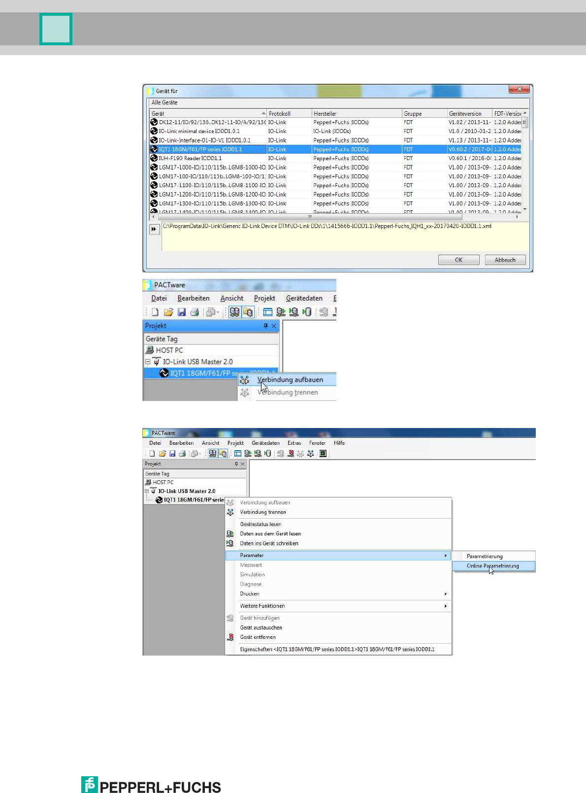
Next, add your read/write head in the same way and set up the connection to it.
2017
-07
17
IO
-
Link RFID Reader, HF
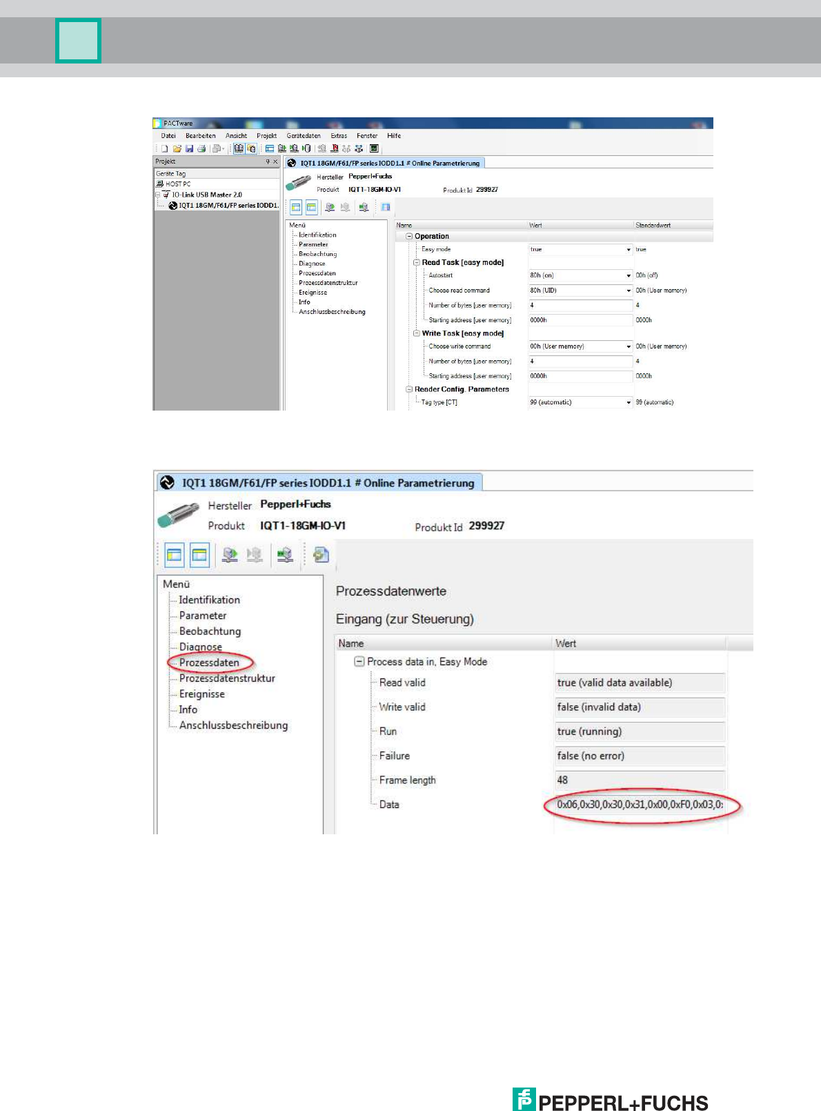
Select the Online Parameterization menu option.
2017
-07
18
IO
-
Link RFID Reader, HF
The read/write head automatically starts reading the UID of the read/write tags. The data can
be found in the input frame of the process data.

2017
-07
19
IO
-
Link RFID Reader, HF
DOCT
-
5706A
06/2017