Pepperl Fuchs IQT1FPIO RFID Reader User Manual tdoct5706A eng
Pepperl + Fuchs Inc RFID Reader tdoct5706A eng
UserManual.wiki
>
Pepperl Fuchs
>
IQT1FPIO User Manual
user manual
Navigation menu
Upload a User Manual
Namespaces
Wiki Guide
HTML
PDF
Info
Views
User Manual
Discussion / Help
Navigation
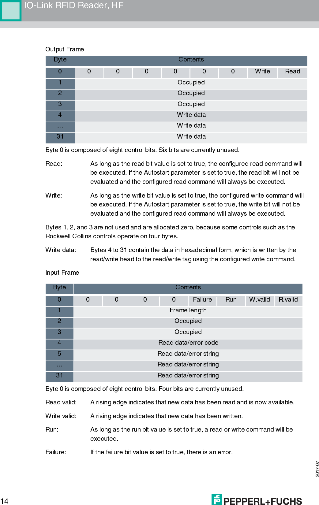
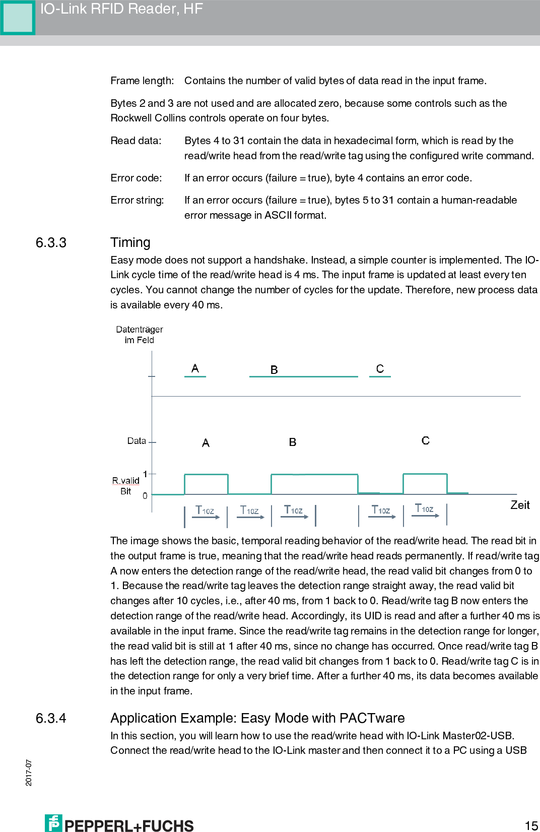
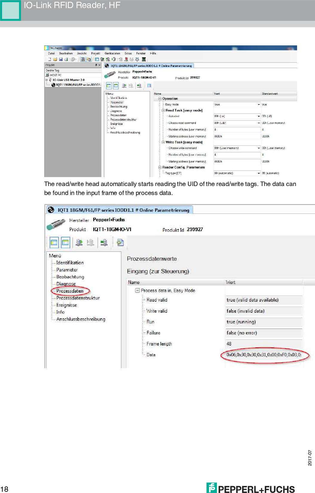
![2017-07 13IO-Link RFID Reader, HF Choose read command This parameter defines the read command that the write/read head will perform at the next reading. Value range: UID, user memory Default value: UID Choose write command This parameter defines the write command that the read/write head will perform at the next writing. Value range: user memory Default value: user memory Number of bytes [user memory] This parameter defines the number of bytes that the next command reads from the user memory or writes to the user memory. The block length of the read/write tags being used and the maximum available data range of 28 bytes per cycle should be observed. Read/write tag type 37 cannot be used in easy mode as its block length of 32 bytes is larger than the maximum available data range. Value range: 4, 8, 12, 16, 20, 24, 28 Default value: 4 Format: decimal Starting address [user memory] This parameter defines the start address from which the next command data is read from the user memory or written to the user memory. The block length of the read/write tag being used and the maximum available data range of 28 bytes per cycle should be observed. Read/write tag type 37 cannot be used in easy mode as its block length of 32 bytes is larger than the maximum available data range. Value range: depends on the size of the user memory and the block length Default value: 0 Format: hexadecimal Autostart This parameter defines whether or not the read command is carried out immediately when you turn on the read/write head without taking into account the control bits of the process data of the output frames. Value range: true, false Default value: true Process Data The process data consists of an output frame and an input frame. The output frame contains the data that is transferred cyclically from the IO-Link master to the reader. The input frame contains the data that is transferred back from the reader to the IO-Link master.](https://usermanual.wiki/Pepperl-Fuchs/IQT1FPIO/User-Guide-3638414-Page-13.png)