Pepperl Fuchs IUH-F190-V1 UHF RFID reader User Manual IUH F190 V1
Pepperl + Fuchs Inc UHF RFID reader IUH F190 V1
UserManual.wiki
>
Pepperl Fuchs
>
IUH F190 V1 User Manual
user manual
Navigation menu
Upload a User Manual
Namespaces
Wiki Guide
HTML
PDF
Info
Views
User Manual
Discussion / Help
Navigation
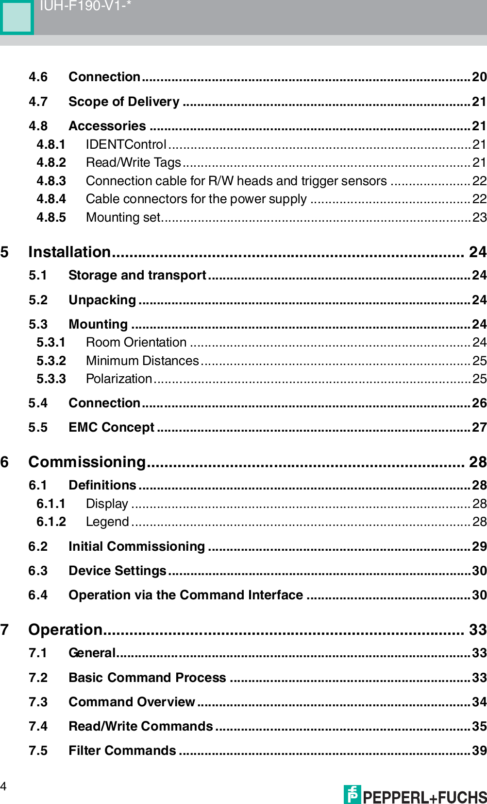
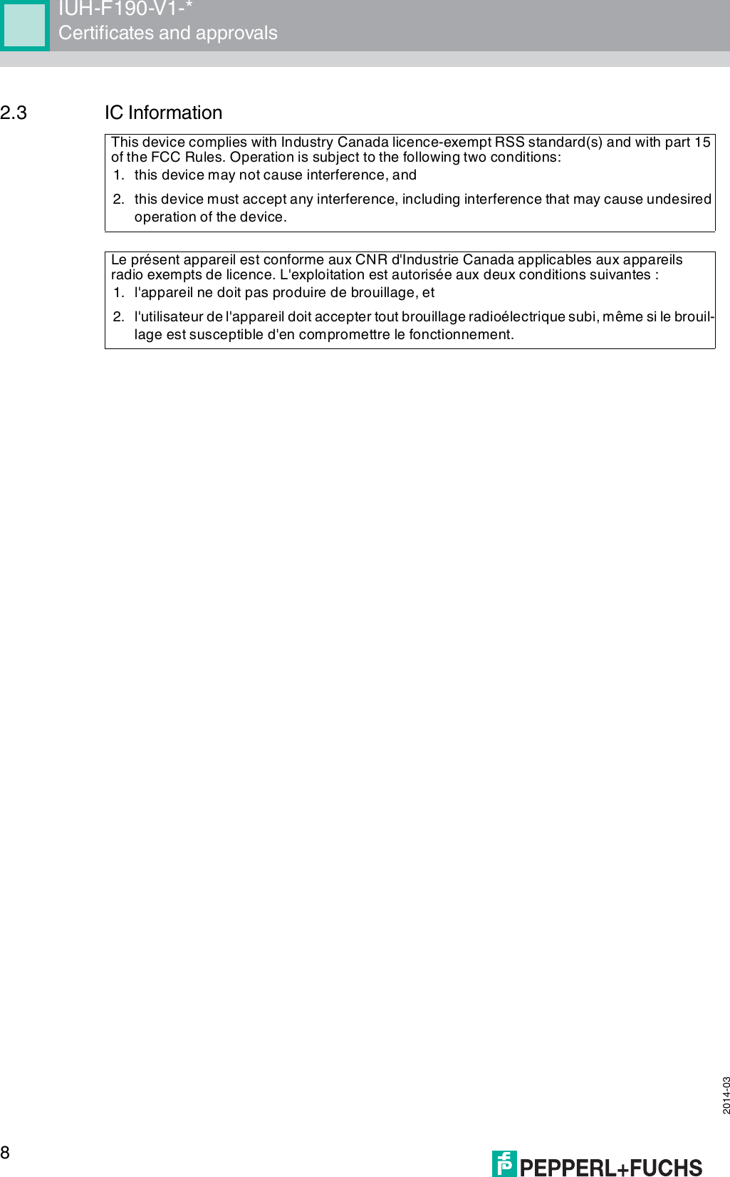
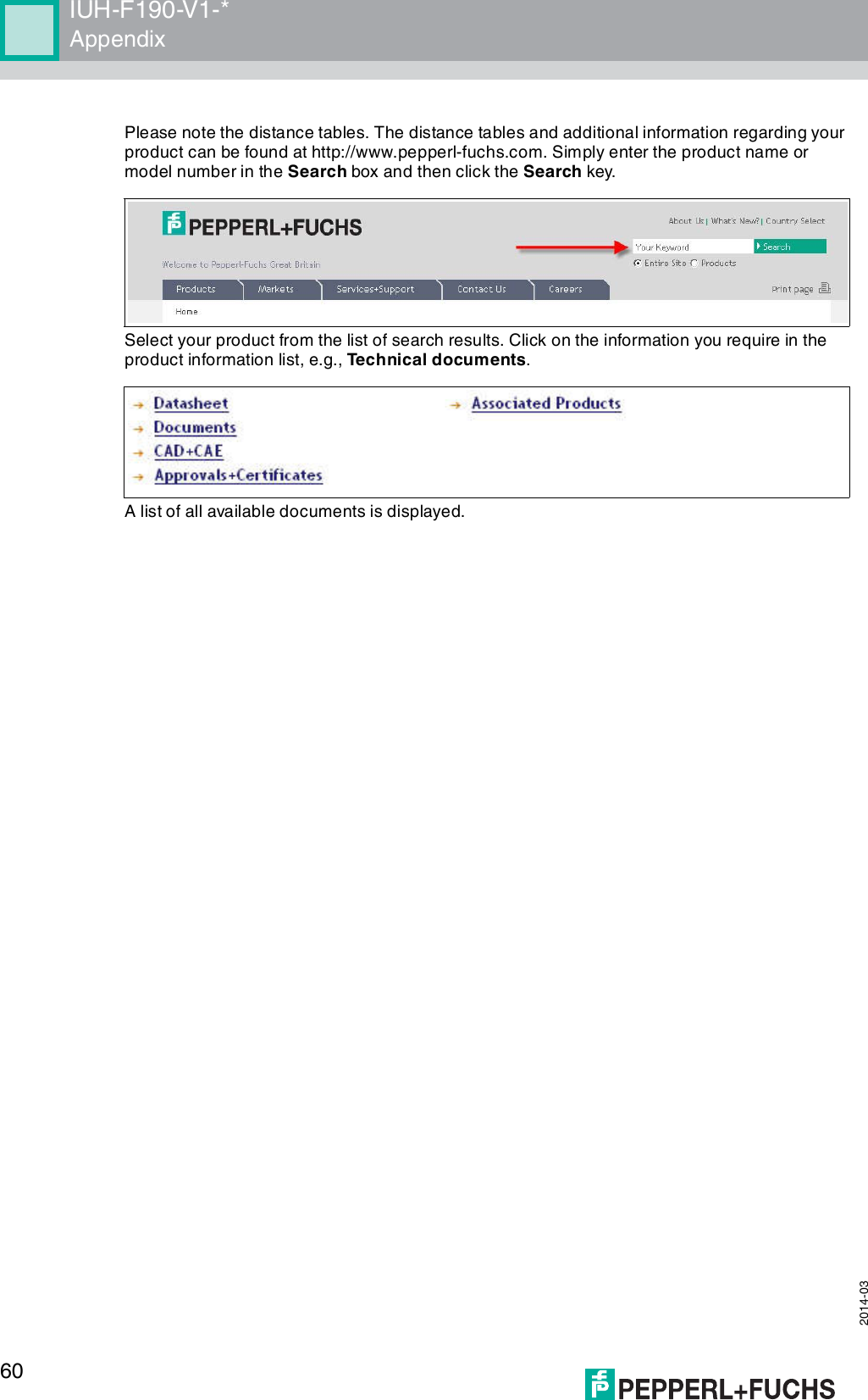
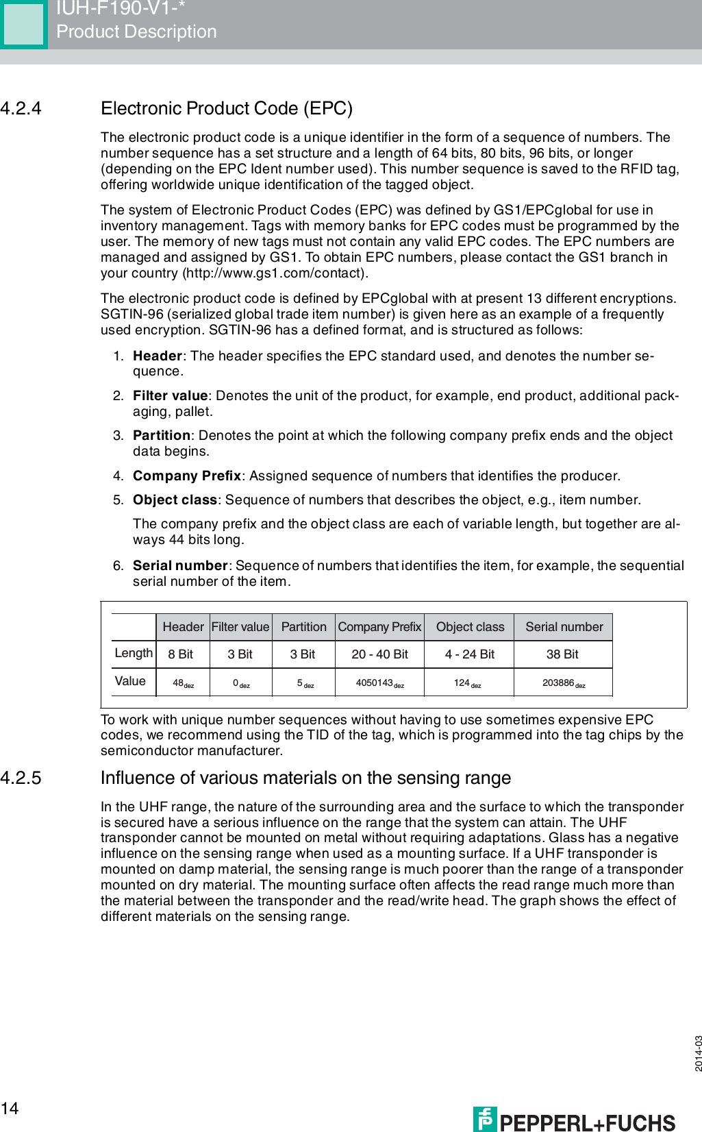
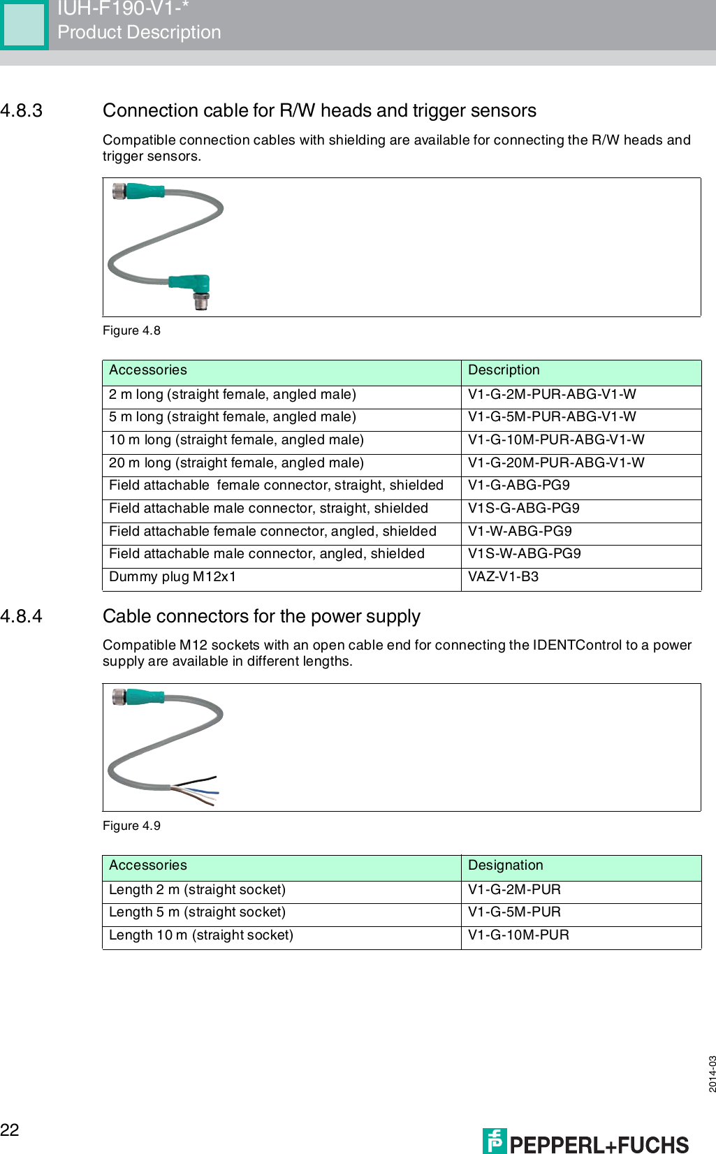
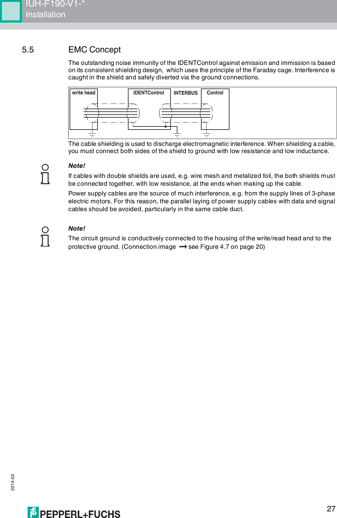
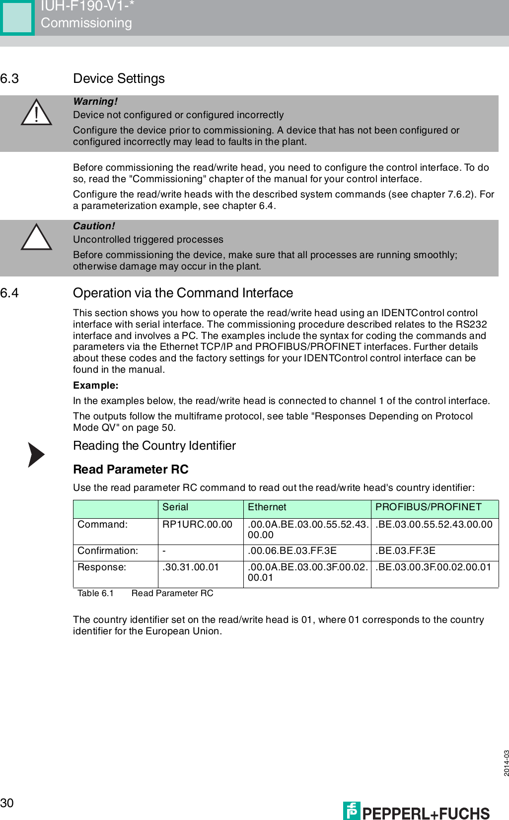
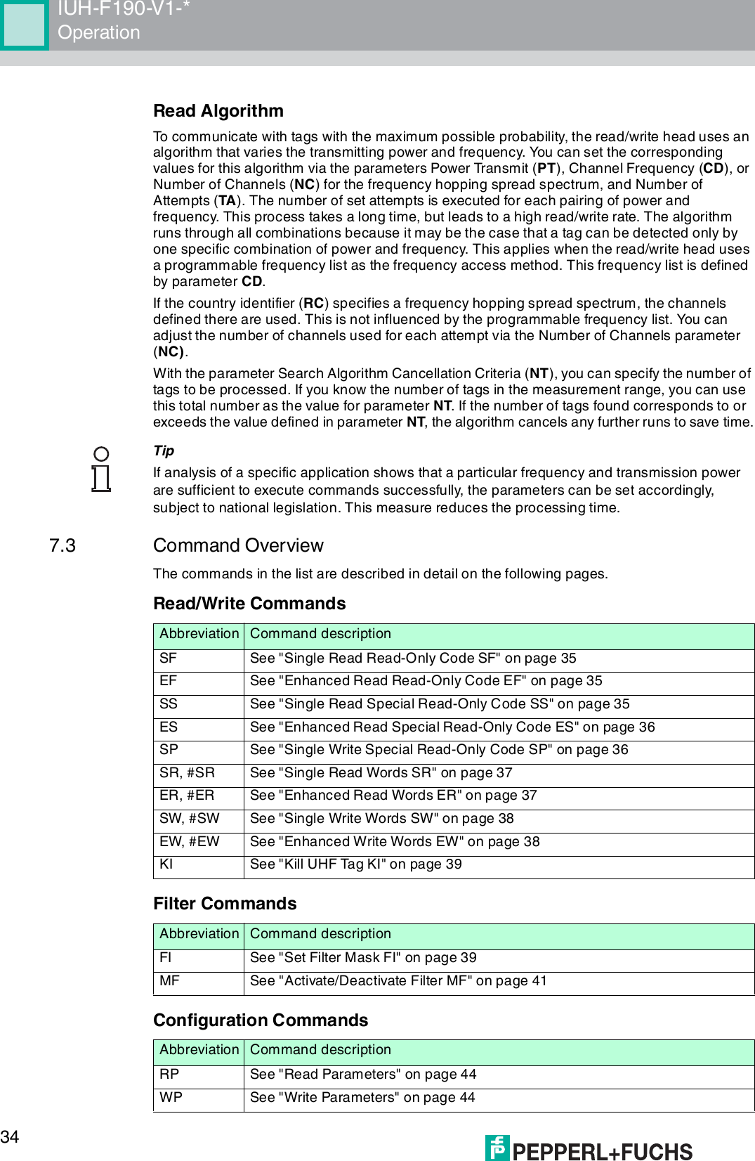
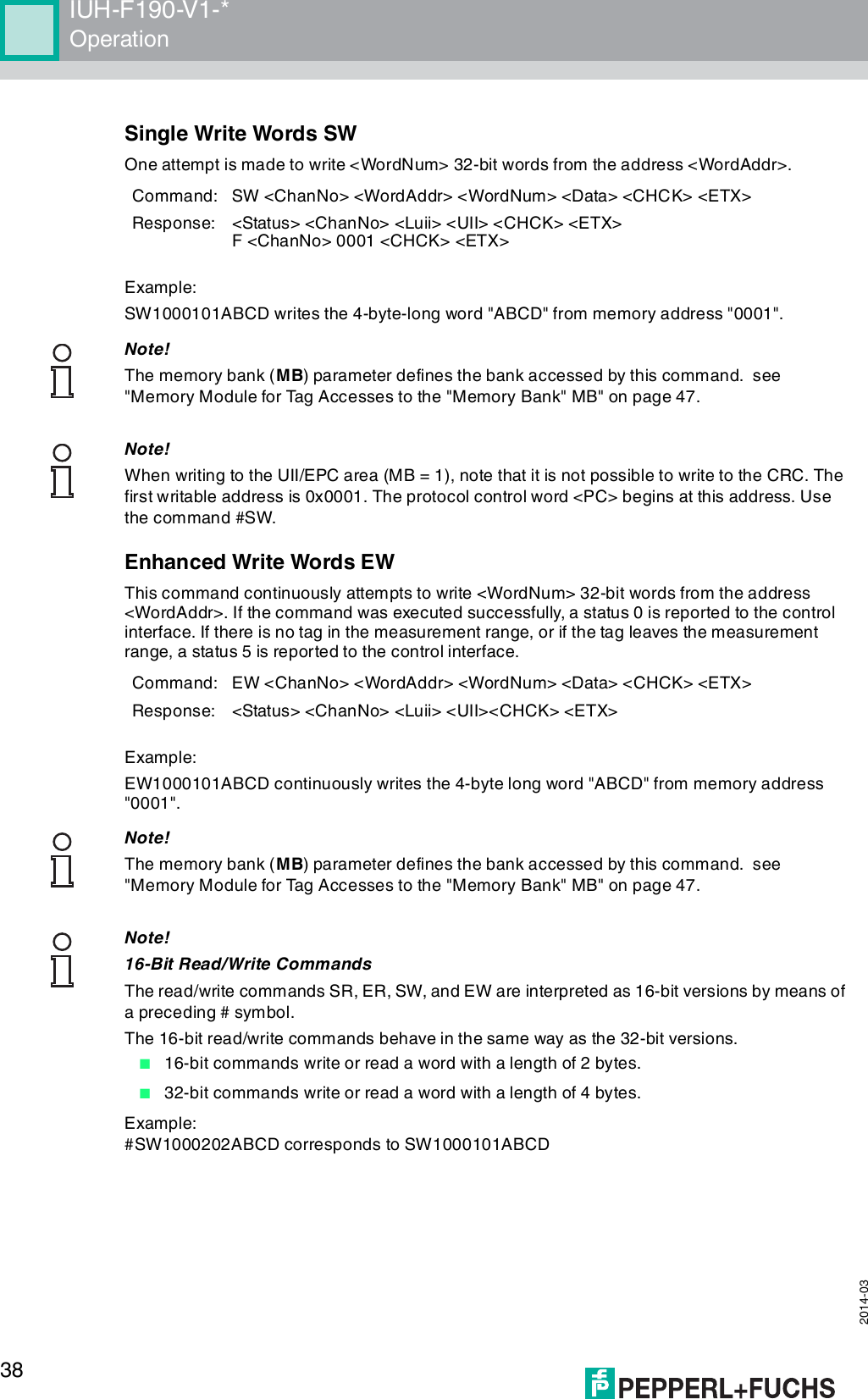
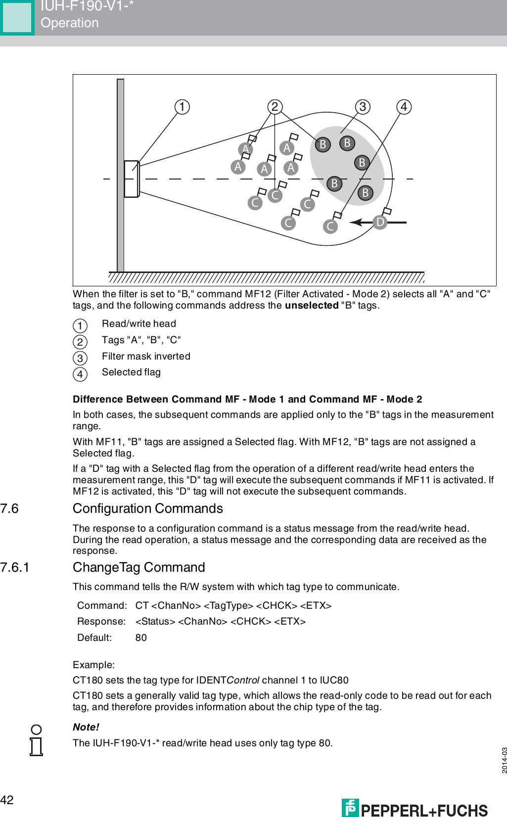
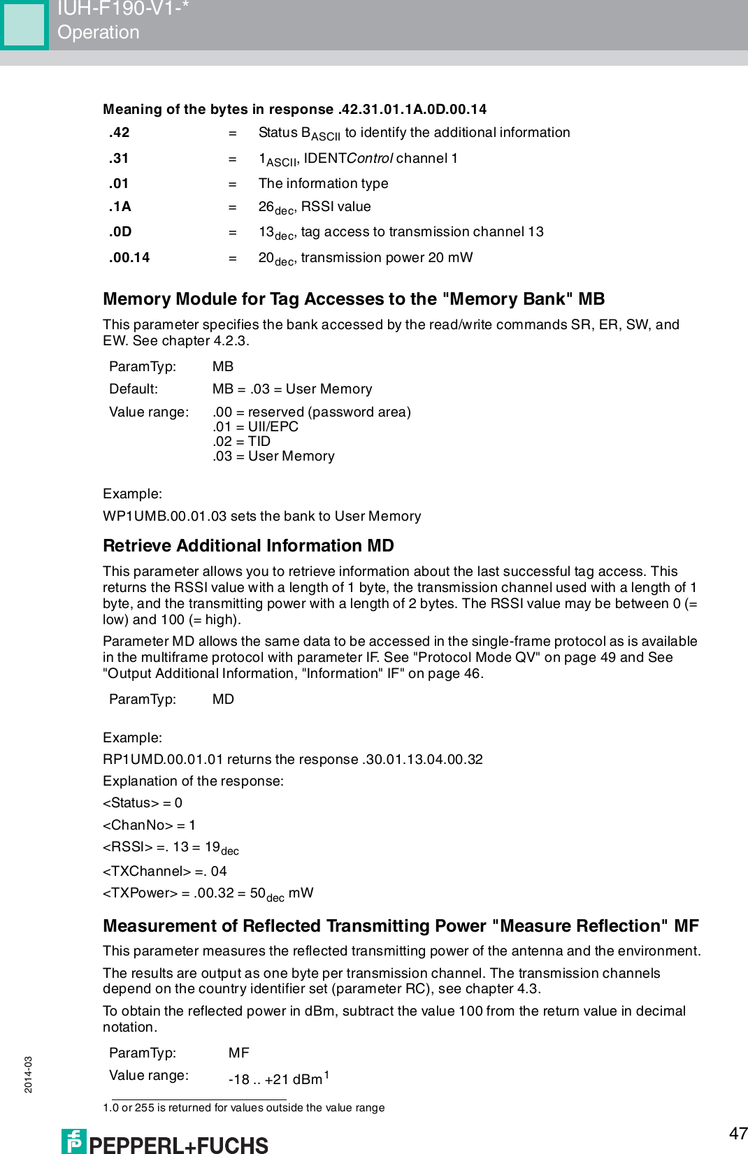
![IUH-F190-V1-*Product Description 2014-03114Product Description4.1 RFID Frequency BandsThe following diagram shows the position of the different frequency bands used for RFID. The IUH-F190-V1-* read/write heads described in this manual operate in the frequency range from 865 MHz ... 868 MHz and from 902 MHz ... 928 MHz, highlighted in color. ■100 kHz ... 135 kHz: Low frequency LF■13.56 MHz: High frequency HF■865 MHz ... 868 MHz (Europe), 902 MHz ... 928 MHz (USA), 920 MHz ... 925 MHz (China): ultra-high frequency UHF■2.45 GHz and 5.8 GHz: Microwave MW4.2 UHF general4.2.1 Advantages of UHF■Long detection range■UHF tags are available as cheap and space-saving adhesive labels■High transfer rates■Tag is available with a large working memory (user memory)■Bulk detection4.2.2 Applications for UHF systems■Identification in galvanic coating or painting systems used in automotive production,■Identification feasible over greater distances than with LF and HF systems,■Identification of automotive superstructures in automotive production,■Pallet identification and measurement of goods movements in the logistics sector, and■Access control at unloading stations with HGV identification.Frequency[MhZ]125 kHz2,45 GHz13,56 MHz5,8 GHz868/915 MHz0,1LF110HF100 1000UHF10000MW](https://usermanual.wiki/Pepperl-Fuchs/IUH-F190-V1/User-Guide-2266324-Page-11.png)
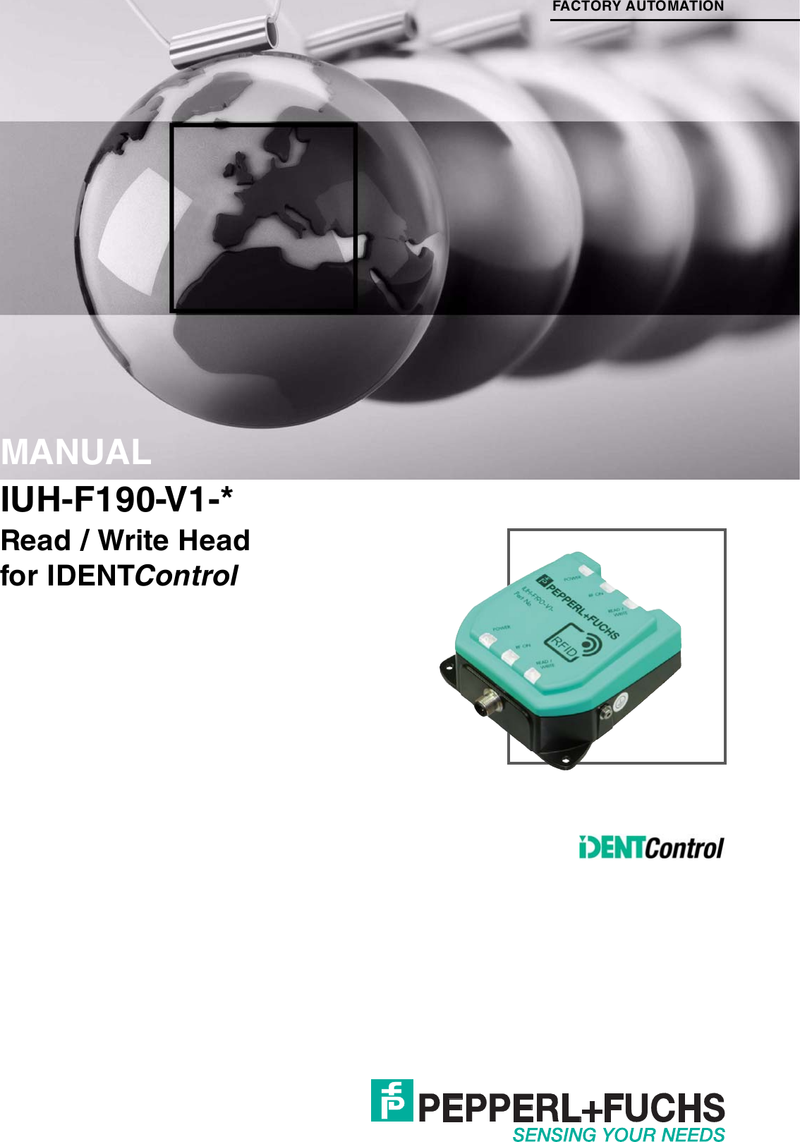
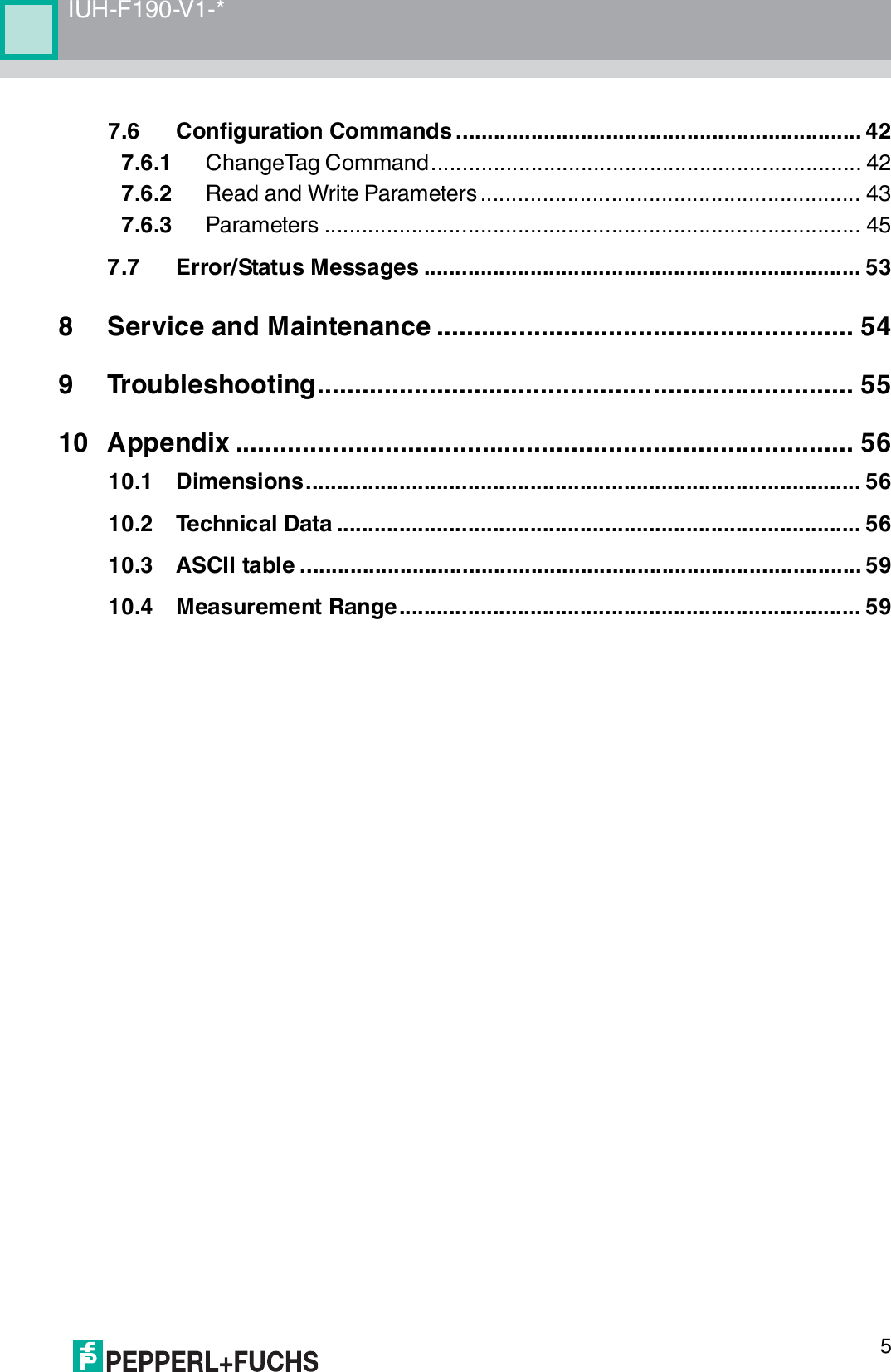
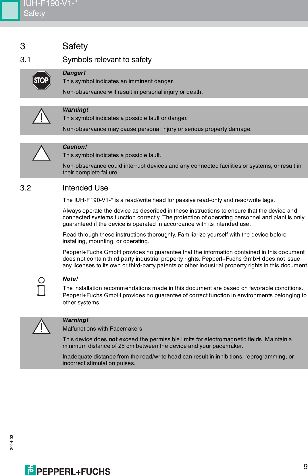
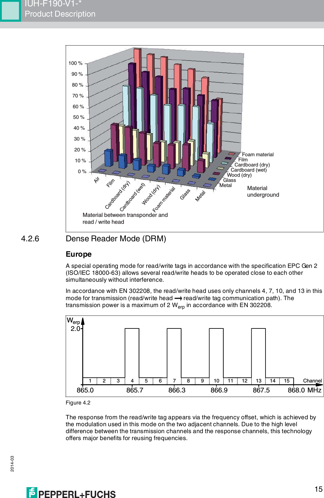
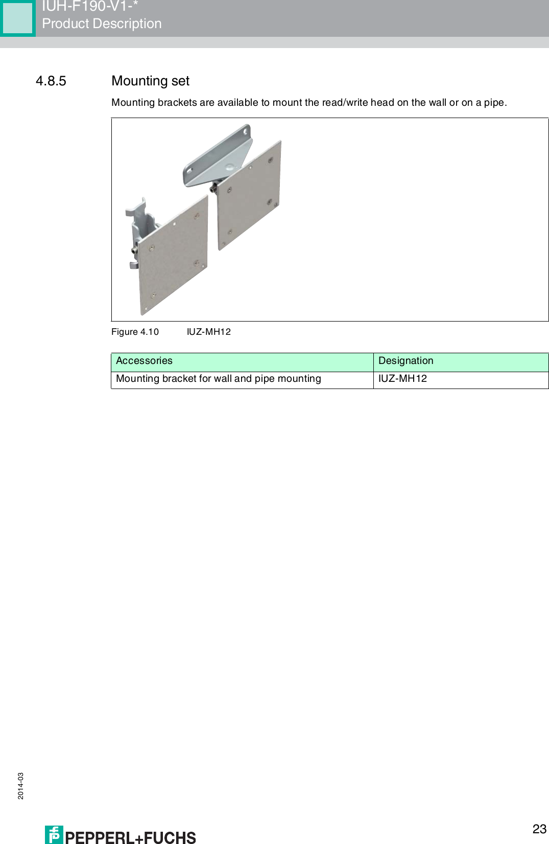
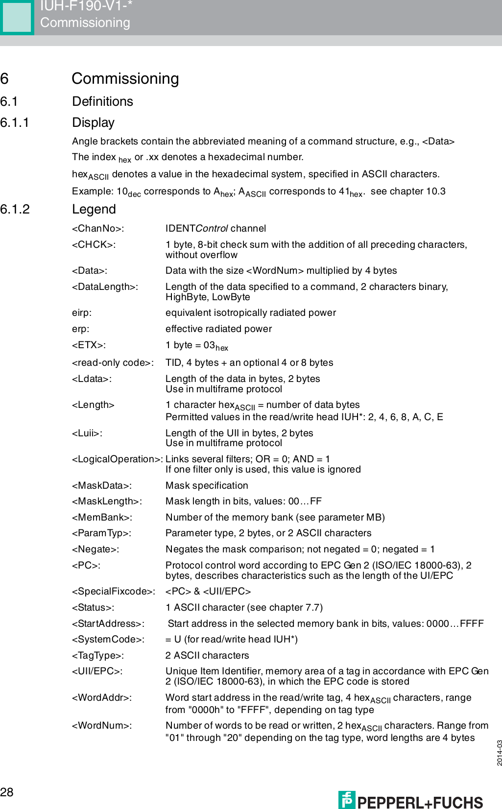
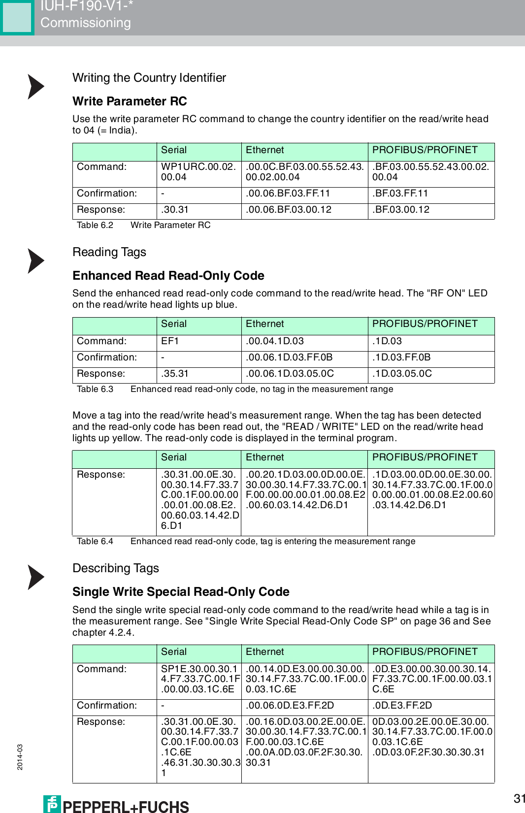
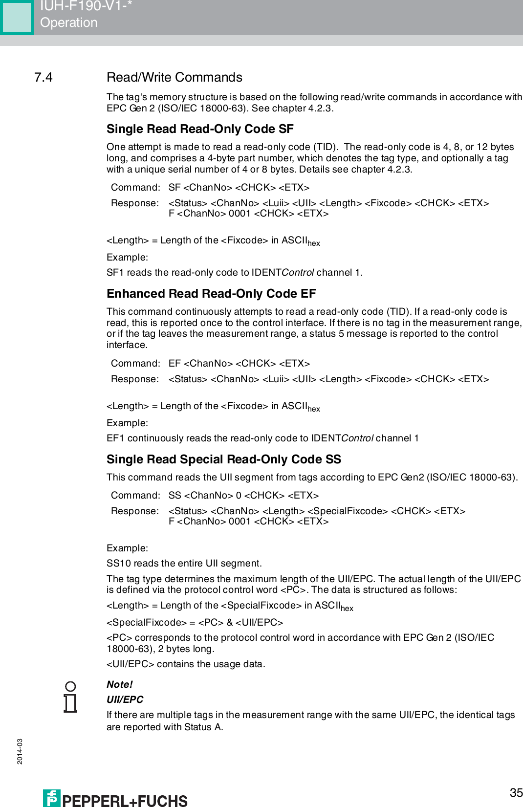
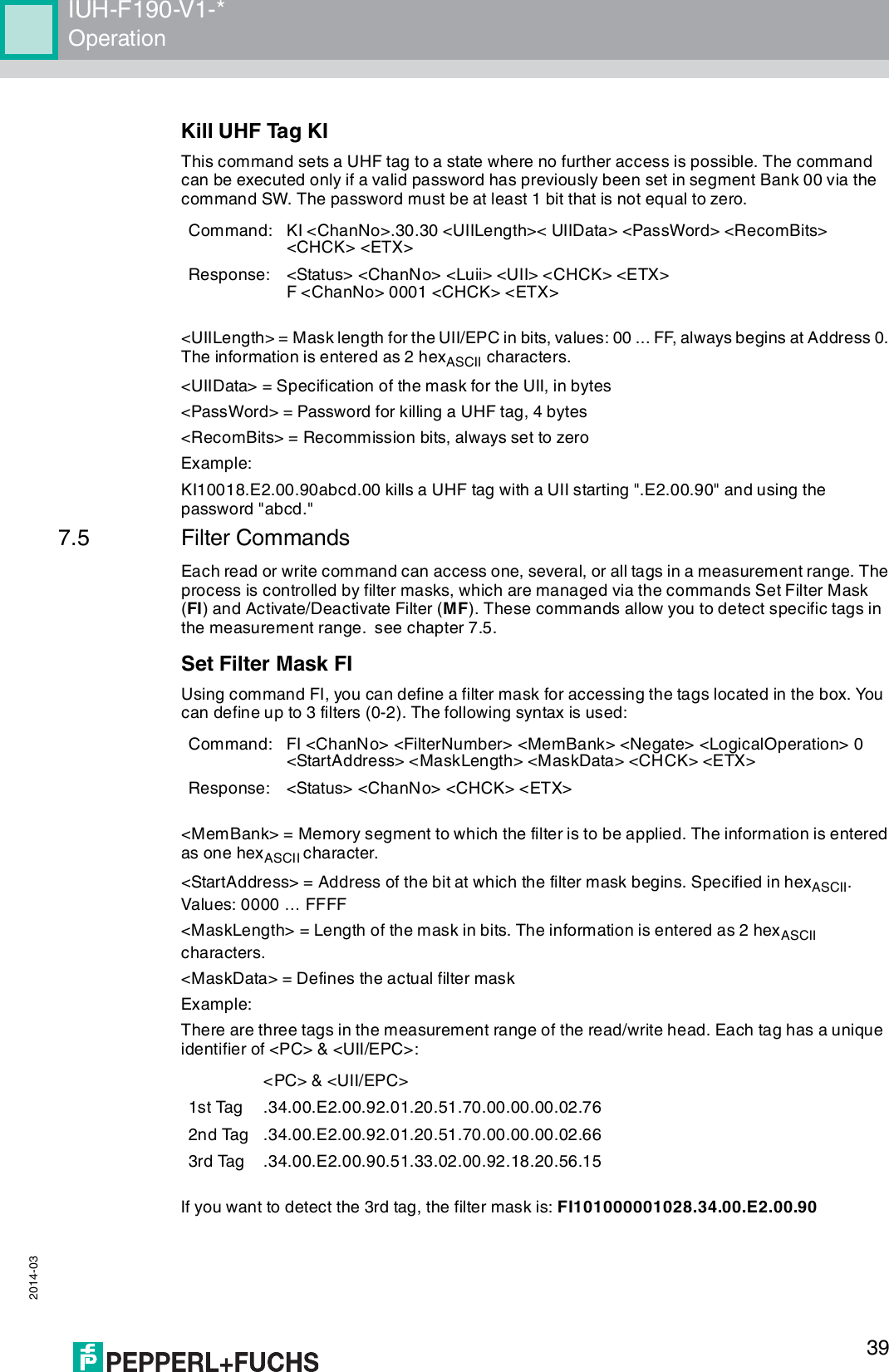
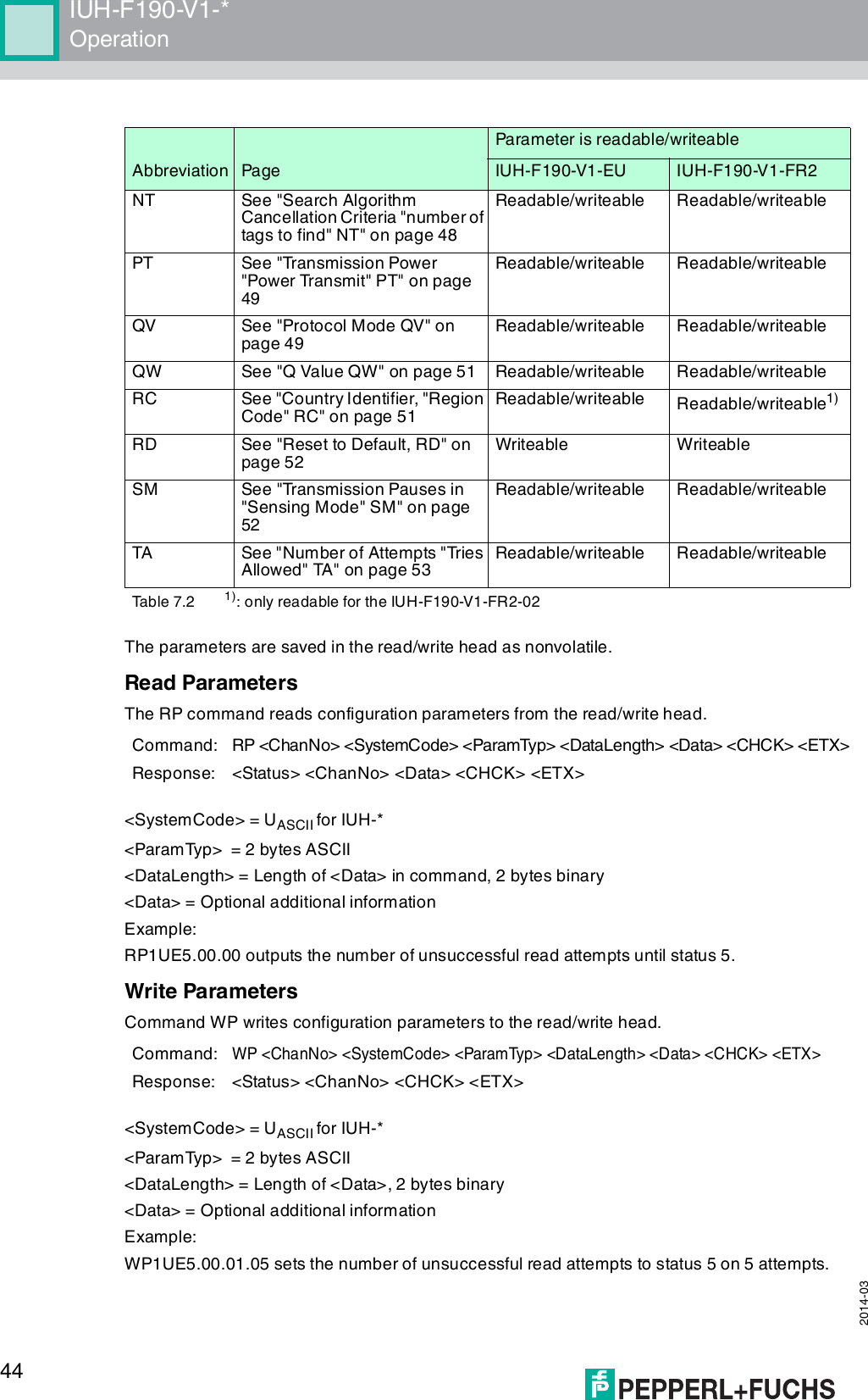
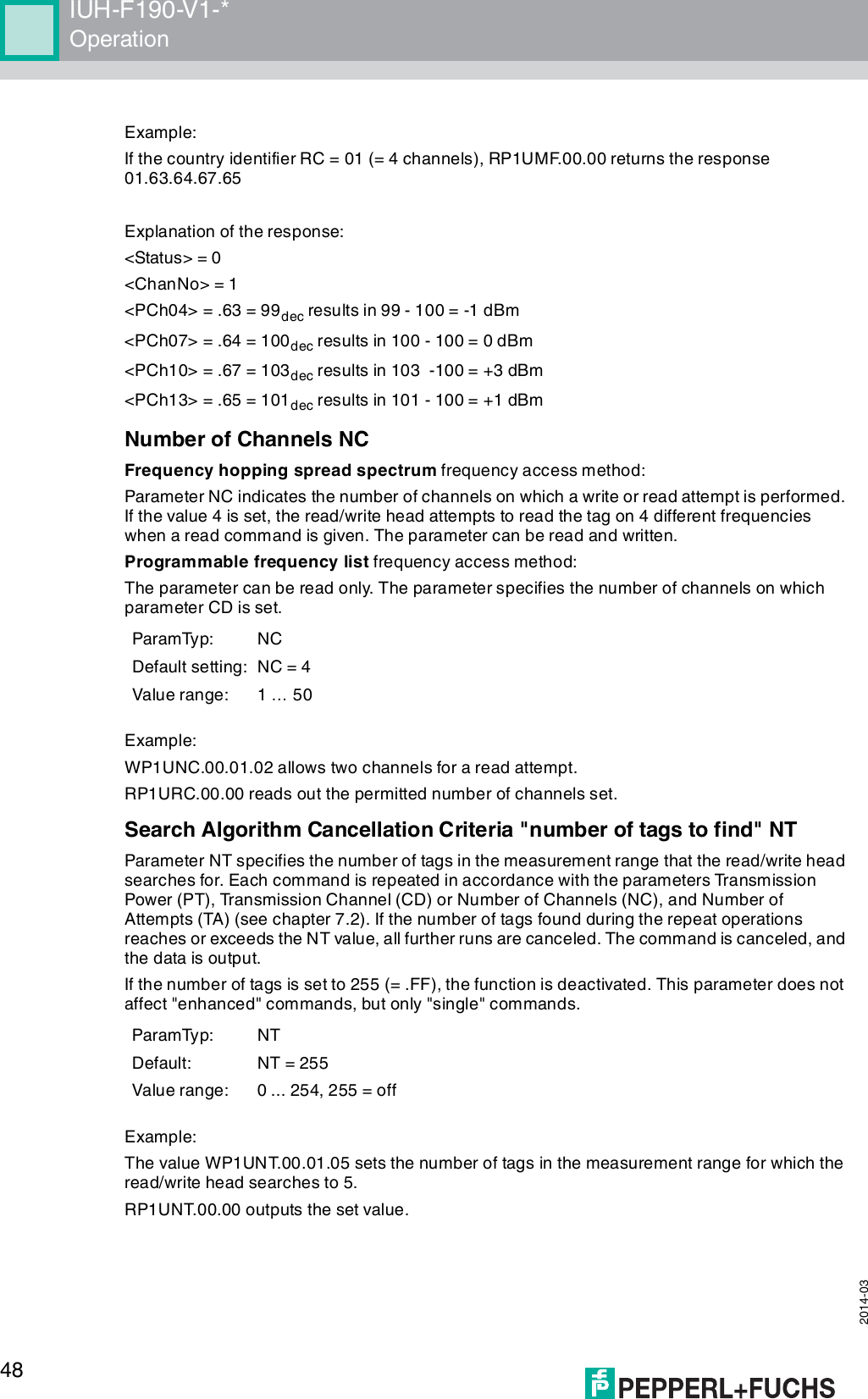
![2014-0312IUH-F190-V1-*Product Description4.2.3 Memory Structure of a Tag in Accordance with EPC Gen 2 (ISO/IEC 18000-63)Figure 4.1The memory module of an EPC Gen 2 (ISO/IEC 18000-63) tag is split into four segments. The main contents of these segments are:Segment Function LengthBank 00(00bin = 0dec)Password managementDepending on the tag type, see table "Tag Types, UHF" on page 43/column "Bank 00"Bank 01(01bin = 1dec)Unique Item Identifier (UII)Electronic Product Code (EPC)Depending on the tag type, see table "Tag Types, UHF" on page 43/column "UII/EPC"Bank 10(10bin = 2dec)Tag ID (TID) 4 bytes (MDID, TMN) + 0, 4, or 8 bytesBank 11(11bin = 3dec)User memory Depending on the tag type, see table "Tag Types, UHF" on page 43/column "User Data"USERTIDUII/EPCRESERVEDRFU [7:0]10h1Fh...MSB LSBDSFID [7:0]00h0FhTID [15:0]10h1Fh...MSB LSBTID [31:16]00h0FhUII/EPC [N:N-15]20h210h2Fh...MSB LSBPC [15:0]10h1FhUII/EPC [15:0]CRC-16 [15:0]00h0FhAccess Password [15:0]30h3Fh...MSB LSBAccess Password [31:16]20h2FhKill Password [15:0]10h1FhKill Password [31:16]00h0FhBank 11Bank 10Bank 01Bank 00SR/ERSW/EWSS/ESSP/EPSF/EF...Optional XPC_W2 [15:0]Optional XPC_W2 [15:0]...220h21Fh22FhMemory moduleCommandsRead / write head](https://usermanual.wiki/Pepperl-Fuchs/IUH-F190-V1/User-Guide-2266324-Page-12.png)
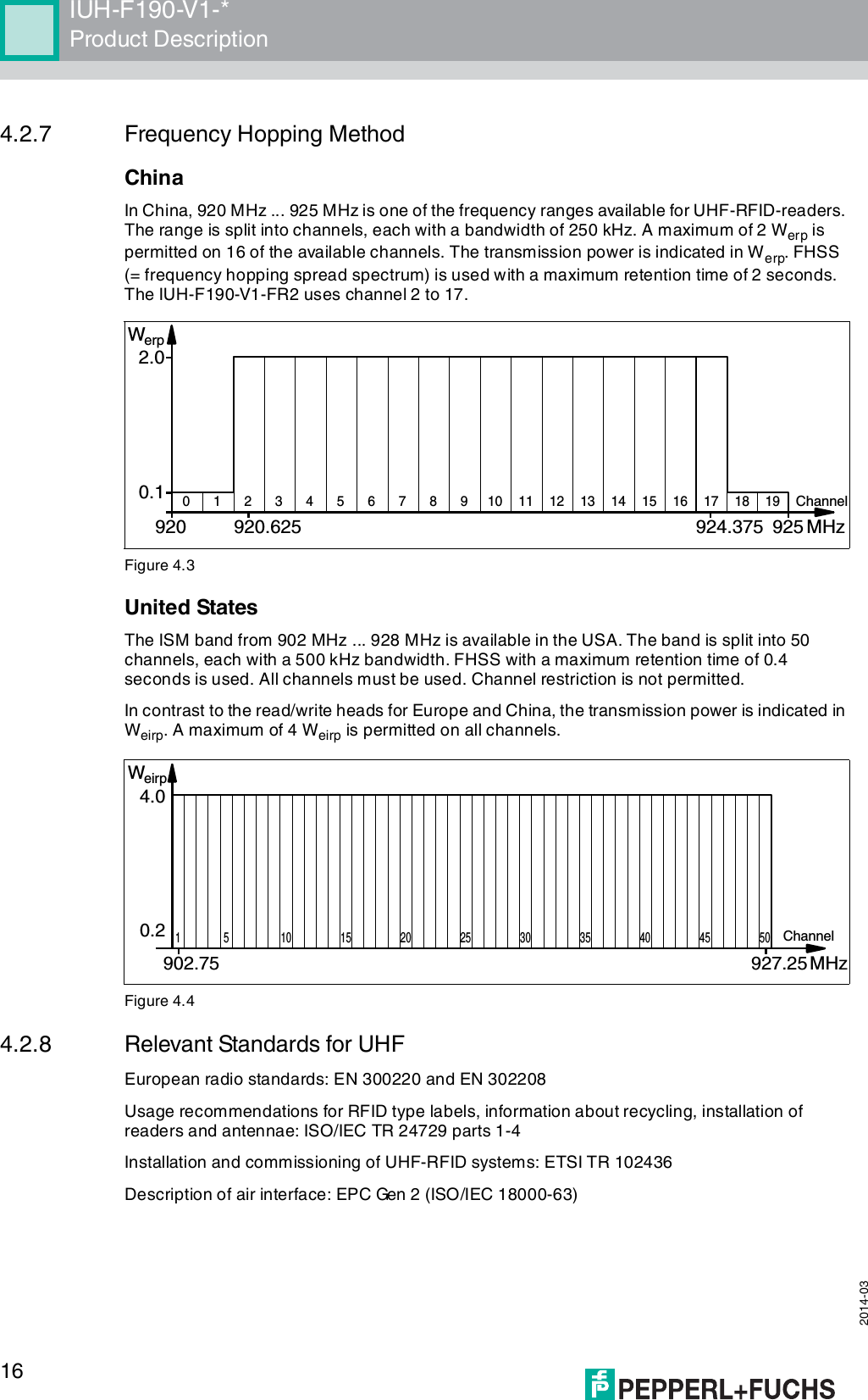
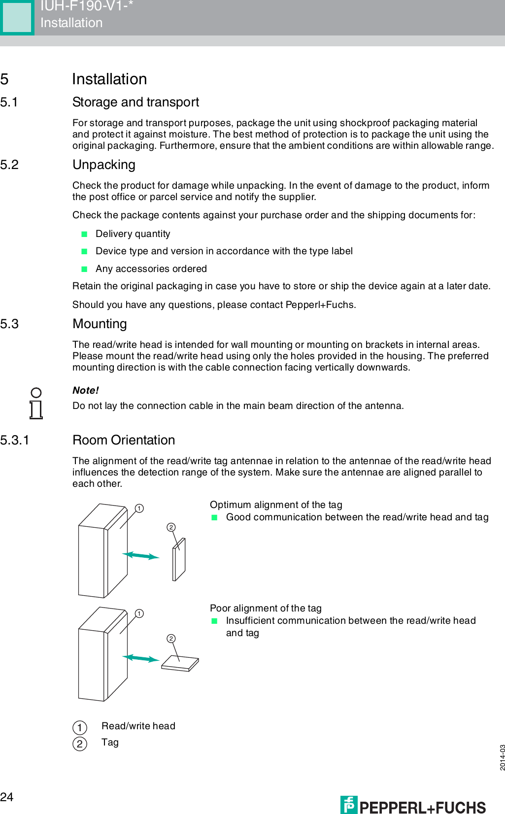
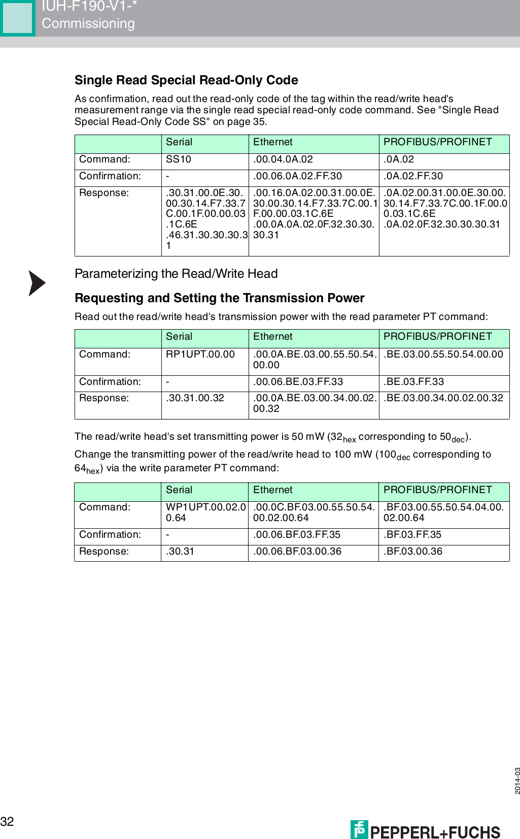
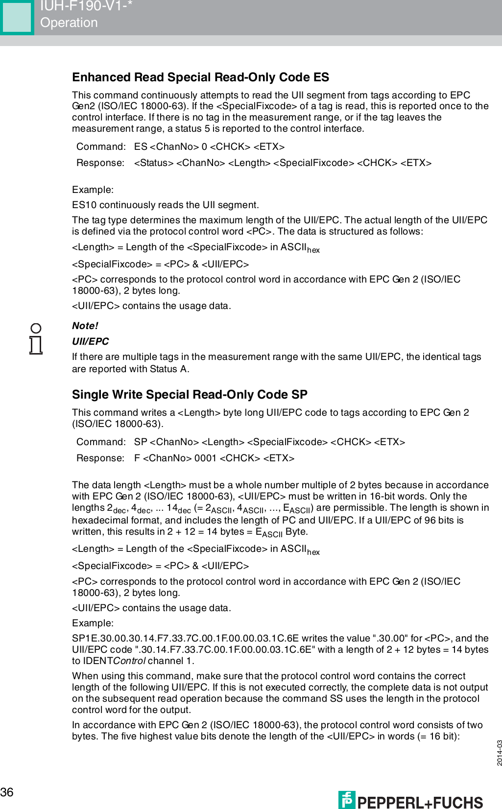
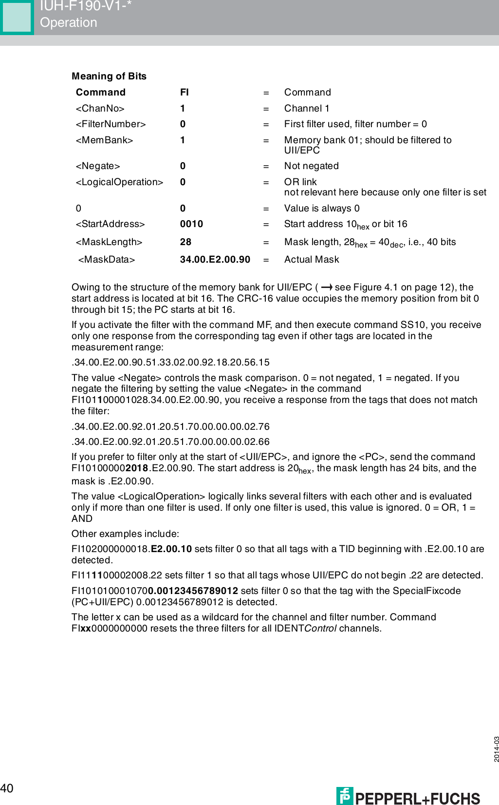
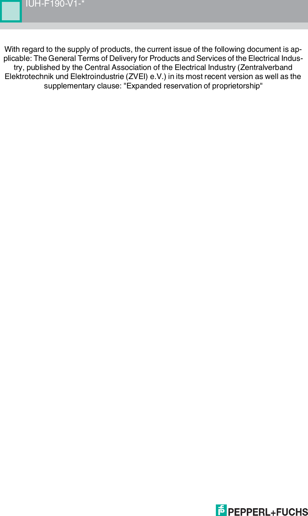
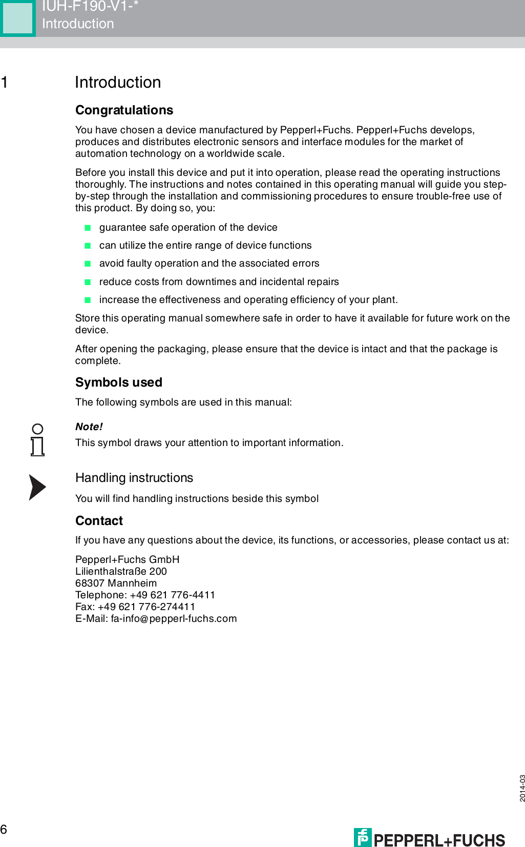
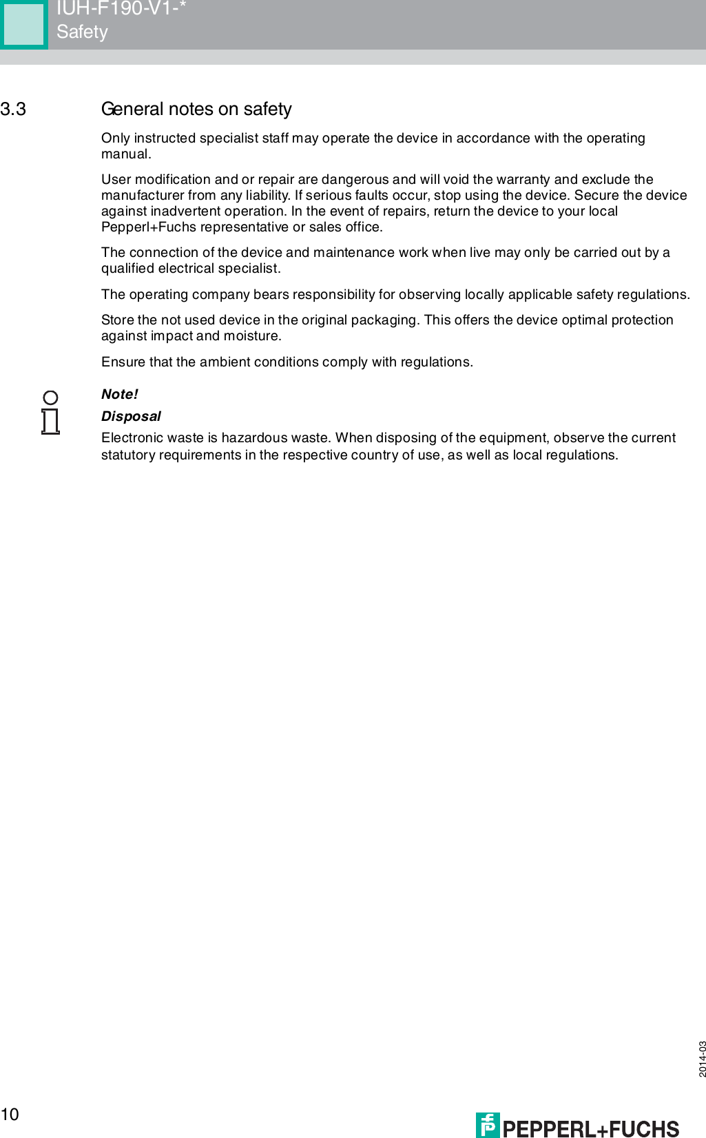
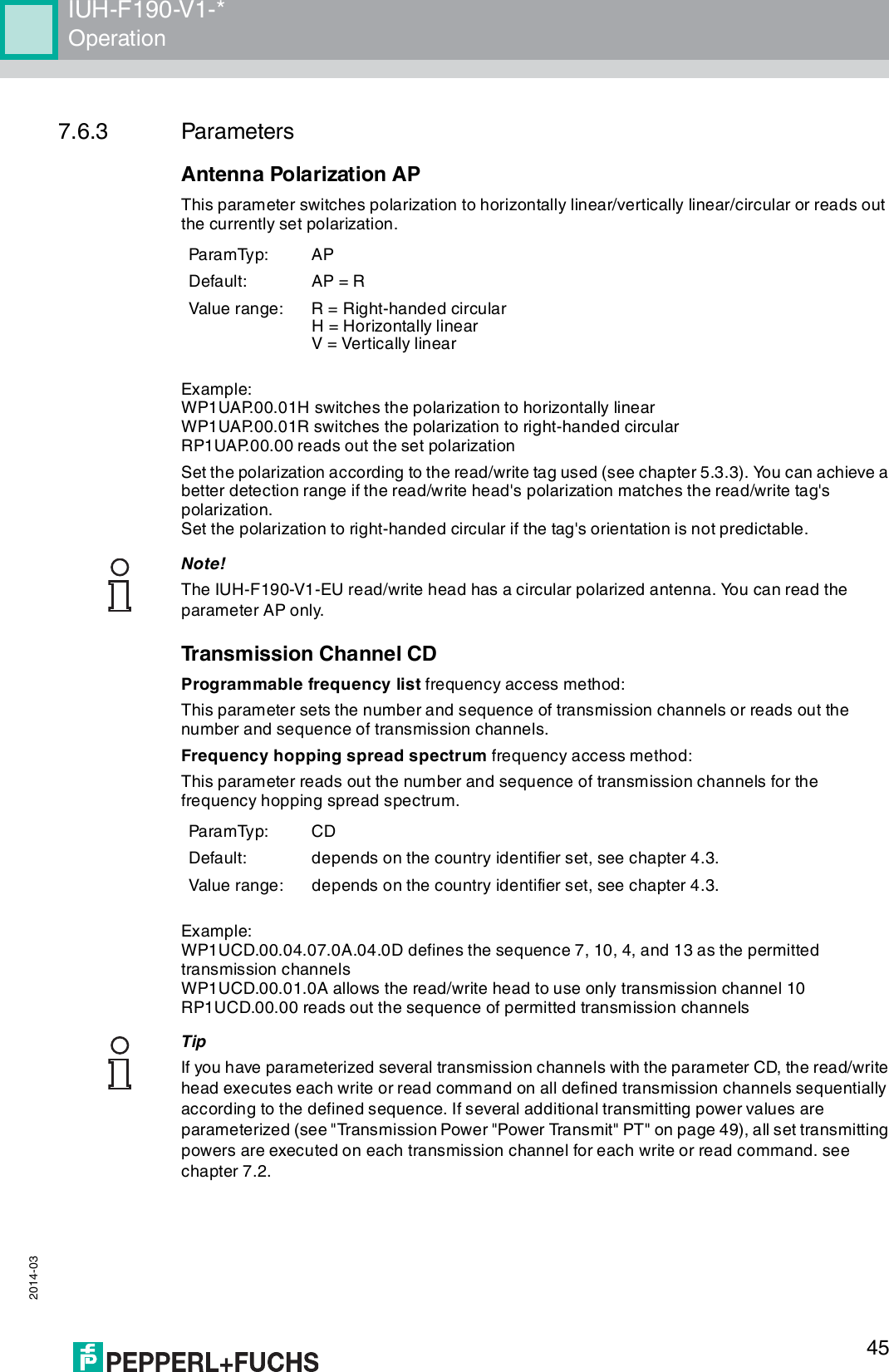
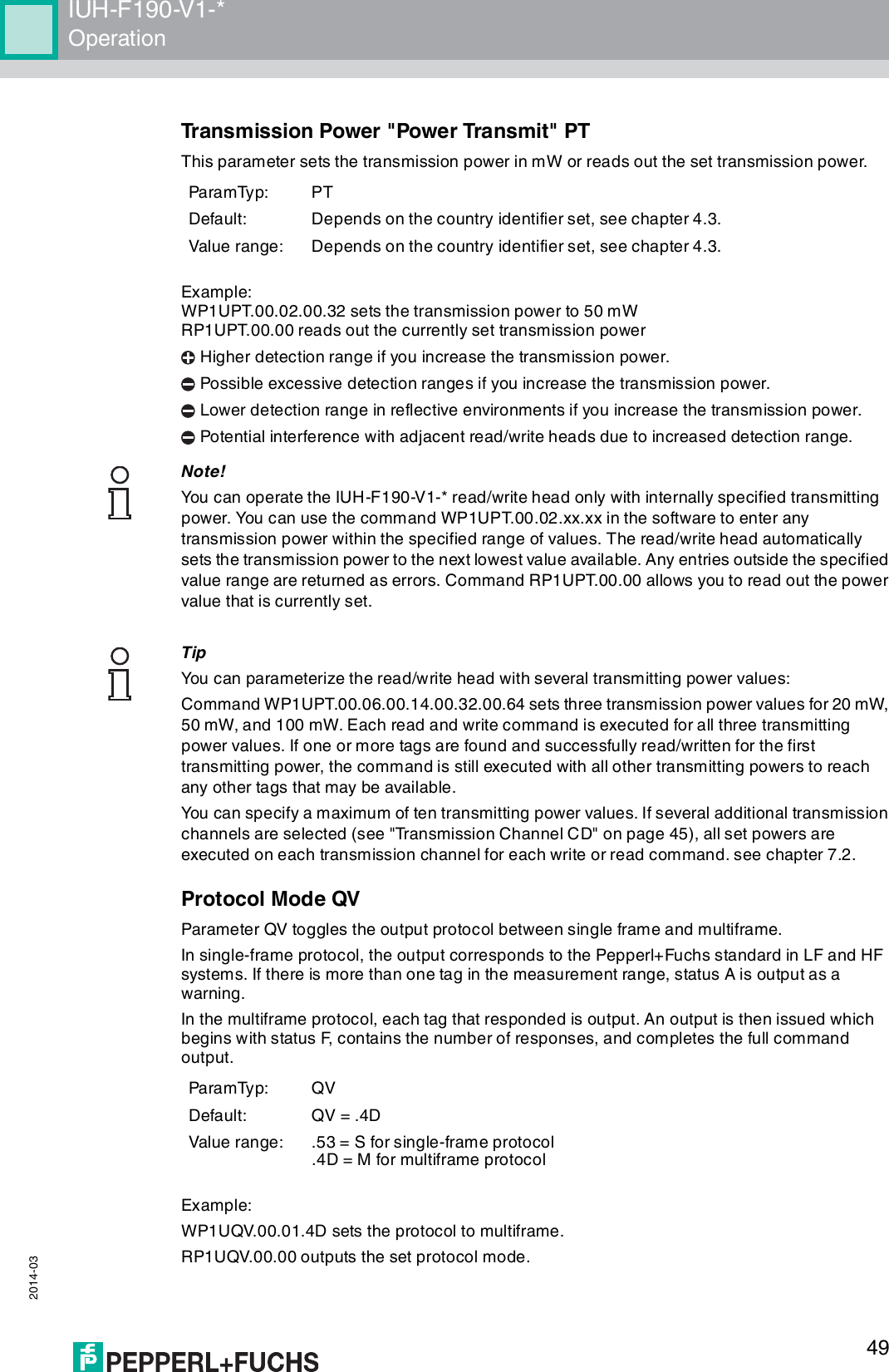
![IUH-F190-V1-*Operation 2014-0343Ta g Ty p es , U H F7.6.2 Read and Write ParametersWith the read parameter (RP) and write parameter (WP) configuration commands, you can read/write the following parameters:Ta g typeChip Pepperl+ Fuchs designationBank 00 [bit]UII / EPC [bit]TID User data [byte]Ty pe Designation Ty p e Unique?72 EPC Class 1 Ge n 2NXP UCode-EPC-G2XMIUC72 32 + 32 240 E2006003hex + seq. no.Ye s 6473 EPC Class 1 Ge n 2Alien Higgs-2 IUC73 32 + 32 96 E2003411hexNo -74 EPC Class 1 Ge n 2NXP UCode-EPC-G2IUC74 32 + 32 96 E2006001hex + seq. no.Ye s 2875 EPC Class 1 Ge n 2Impinj Monza 2.0 IUC75 32 + 32 96 E2001071hexNo -76 EPC Class 1 Ge n 2Alien Higgs-3 IUC76 32 + 32 96 E2003412hex + seq. no.Ye s 6477 EPC Class 1 Ge n 2Impinj Monza 4QT IUC77 32 + 32 96 E2801105hex + seq. no.No 6480 EPC Class 1 Ge n 2Read/write tag conforms with Class 1 Gen 2IUC801) 1)E2xxxxxxhex + seq. no.1) 1)Table 7.1 Tag types1) = depending on the tag typeAbbreviation PageParameter is readable/writeableIUH-F190-V1-EU IUH-F190-V1-FR2AP See "Antenna Polarization AP" on page 45Readable Readable/writeableCD See "Transmission Channel CD" on page 45Readable/writeable for RC = 1, 4, 5, 6Readable for RC = 2, 3E5 See "Number of Unsuccessful Attempts until Status 5 "Enhanced Status 5" E5" on page 46Readable/writeable Readable/writeableFL See "Read Out Filter Mask "Filter List" FL" on page 46Readable ReadableIF See "Output Additional Information, "Information" IF" on page 46Readable/writeable Readable/writeableMB See "Memory Module for Tag Accesses to the "Memory Bank" MB" on page 47Readable/writeable Readable/writeableMD See "Retrieve Additional Information MD" on page 47Readable ReadableMF See "Measurement of Reflected Transmitting Power "Measure Reflection" MF" on page 47Readable ReadableNC See "Number of Channels NC" on page 48Readable/writeable for RC = 2, 3Readable for RC = 1, 4, 5, 6](https://usermanual.wiki/Pepperl-Fuchs/IUH-F190-V1/User-Guide-2266324-Page-43.png)
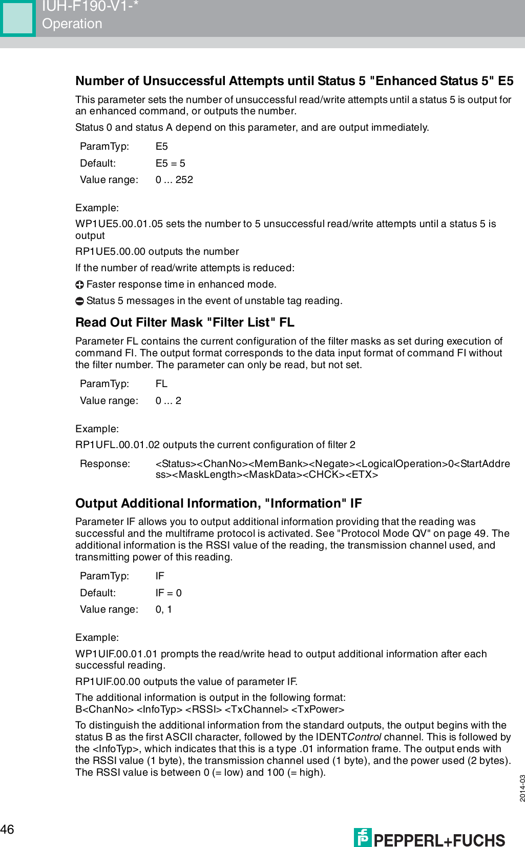
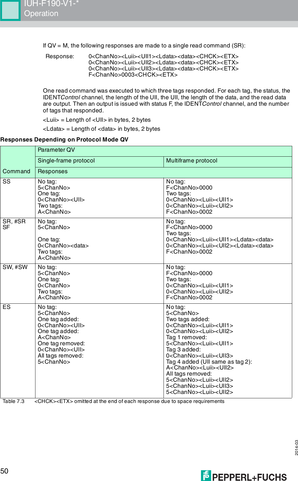
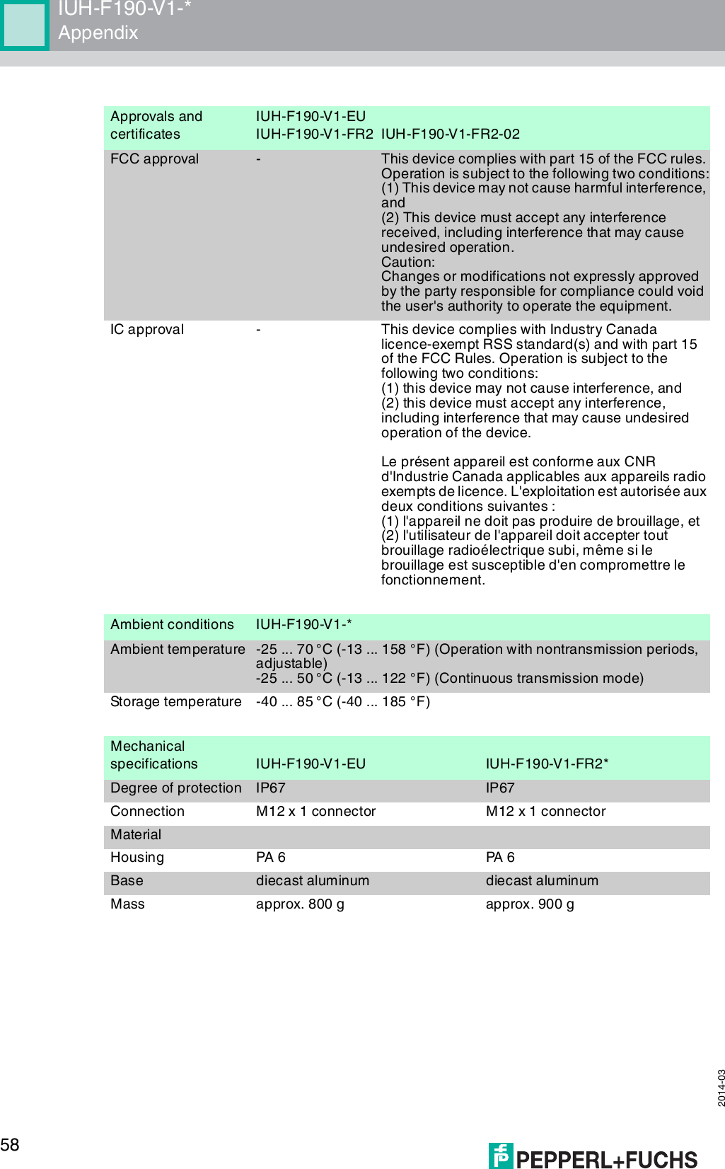
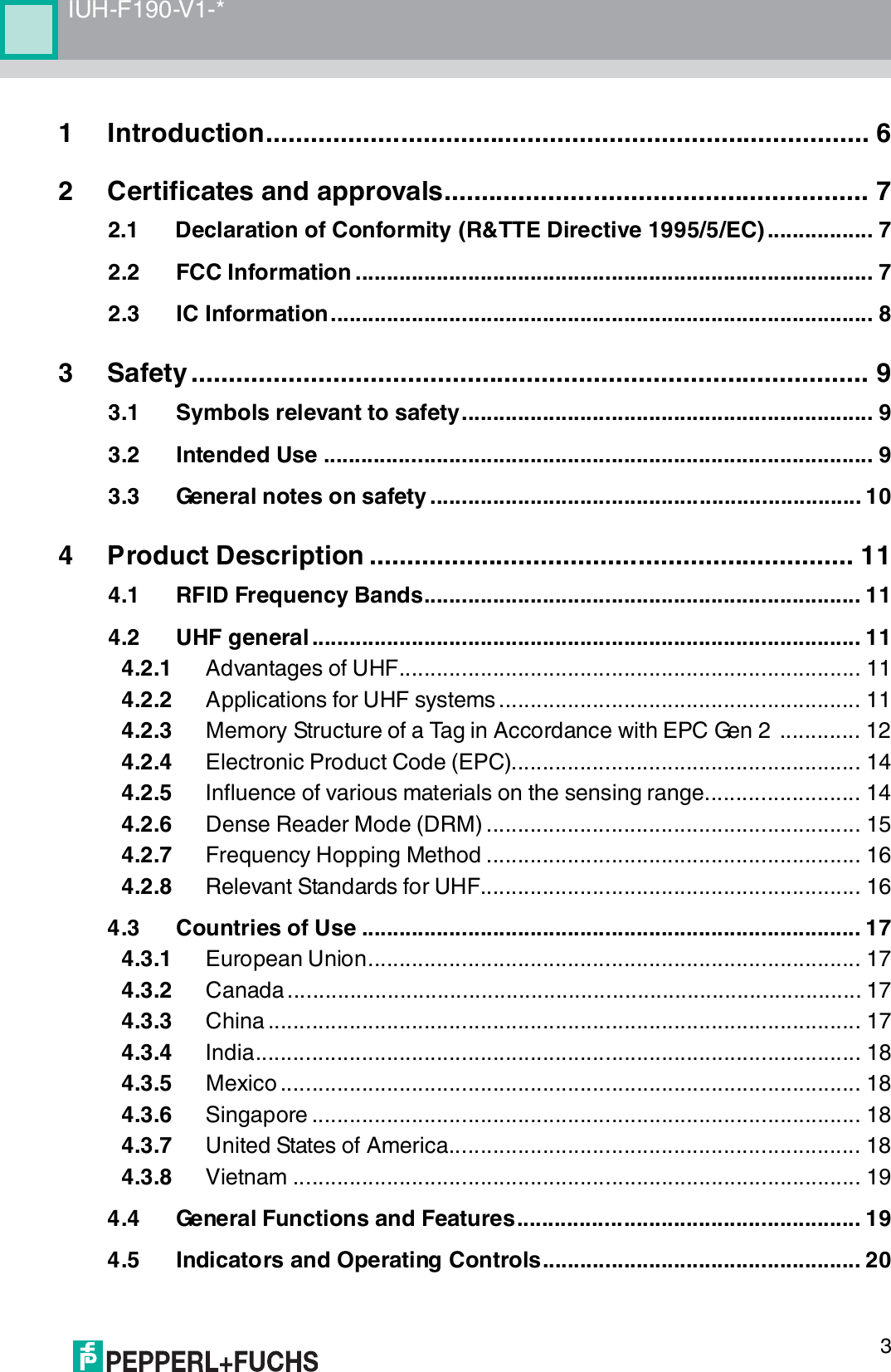
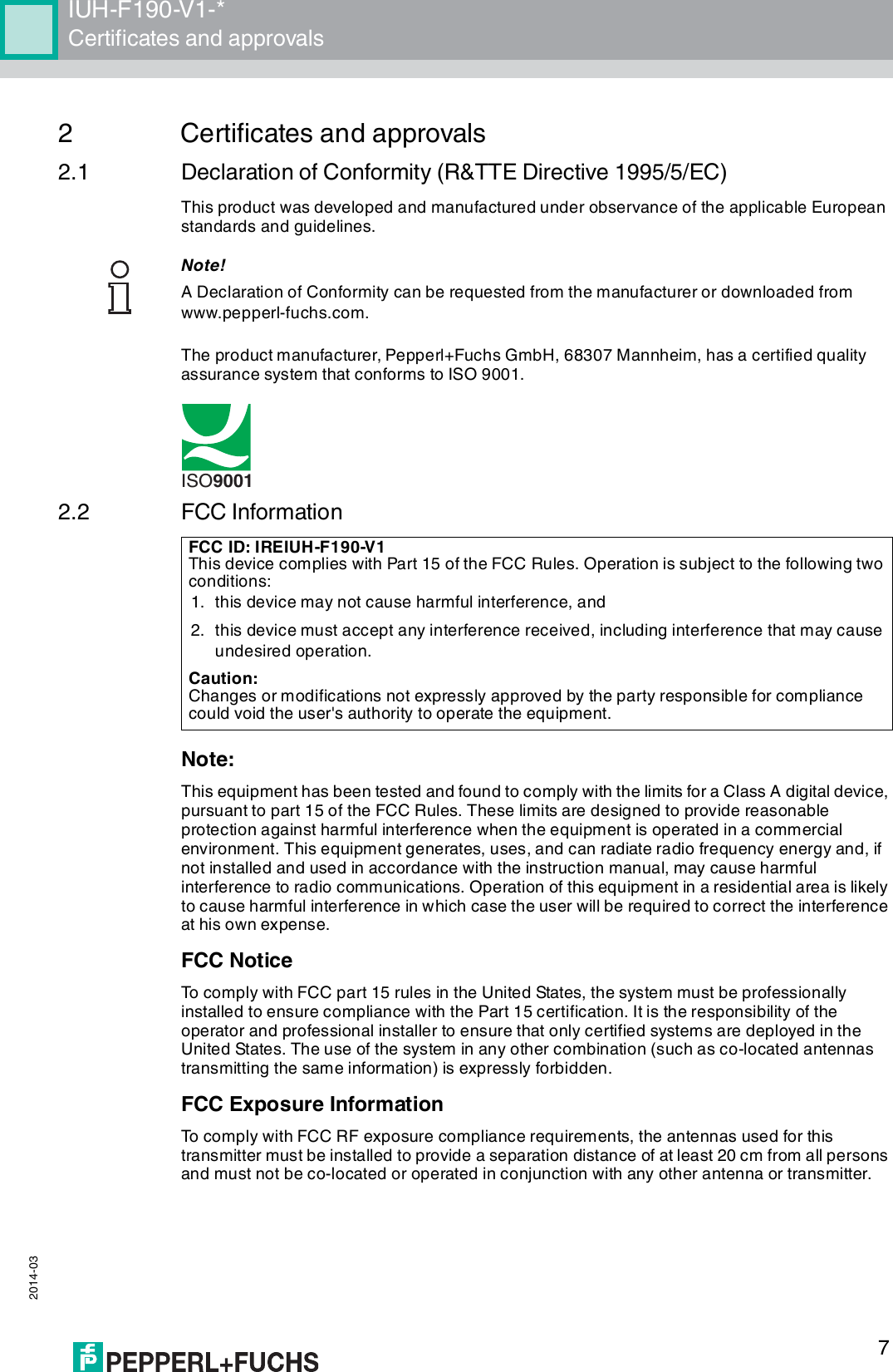
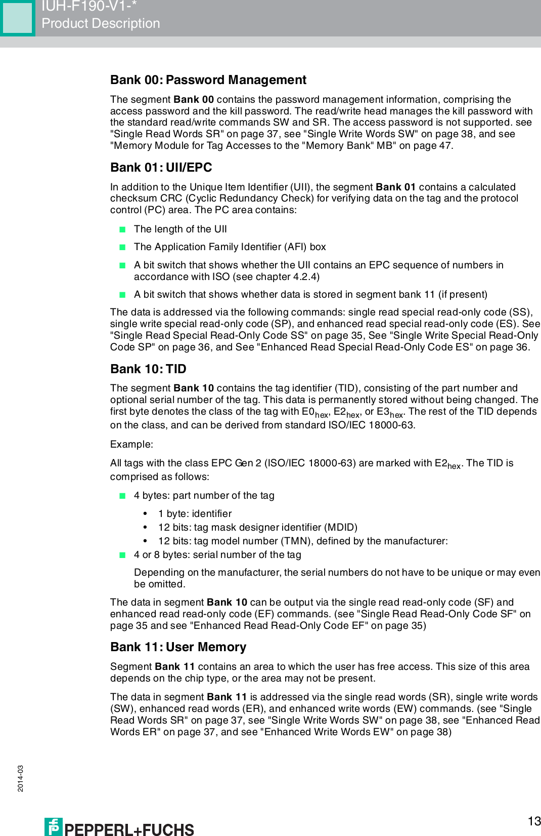
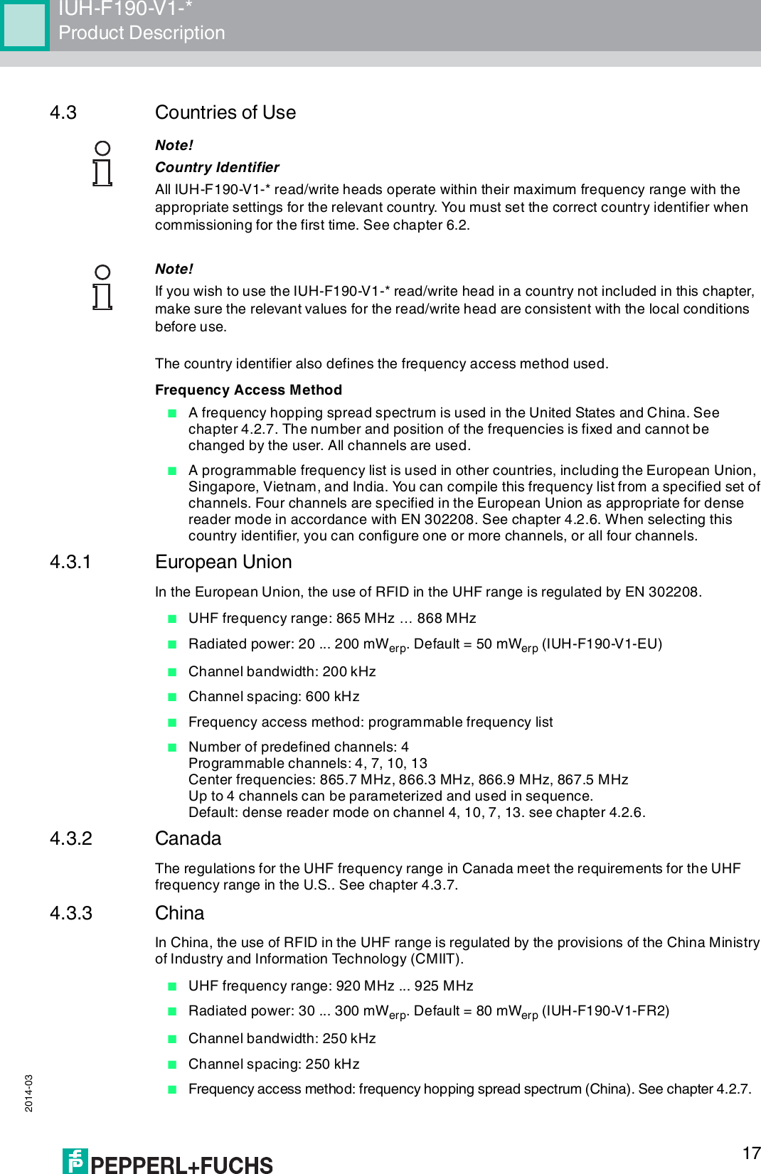
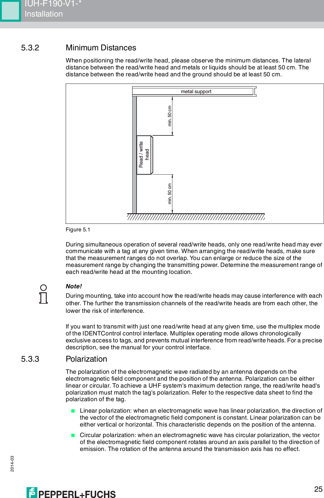
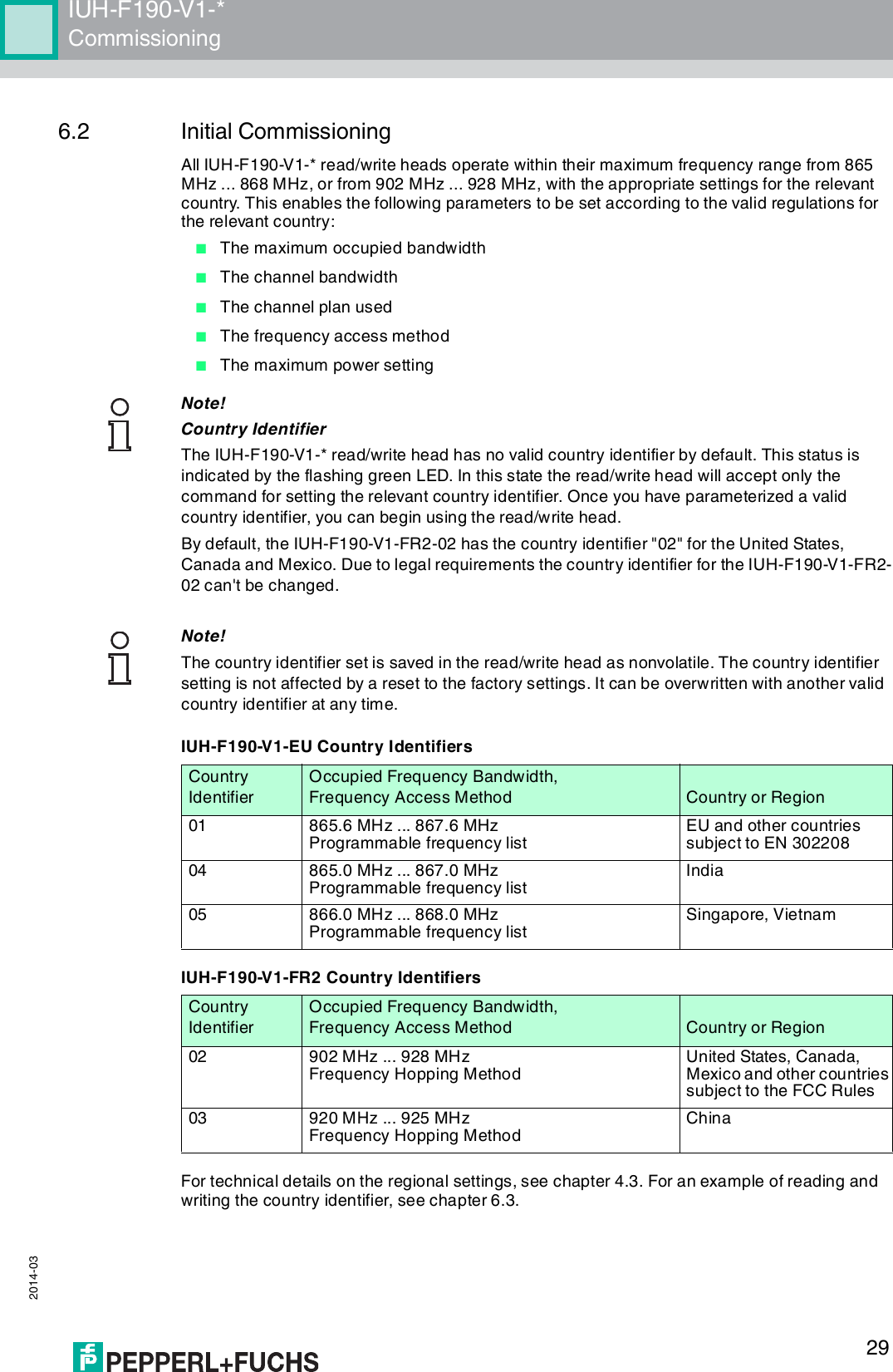
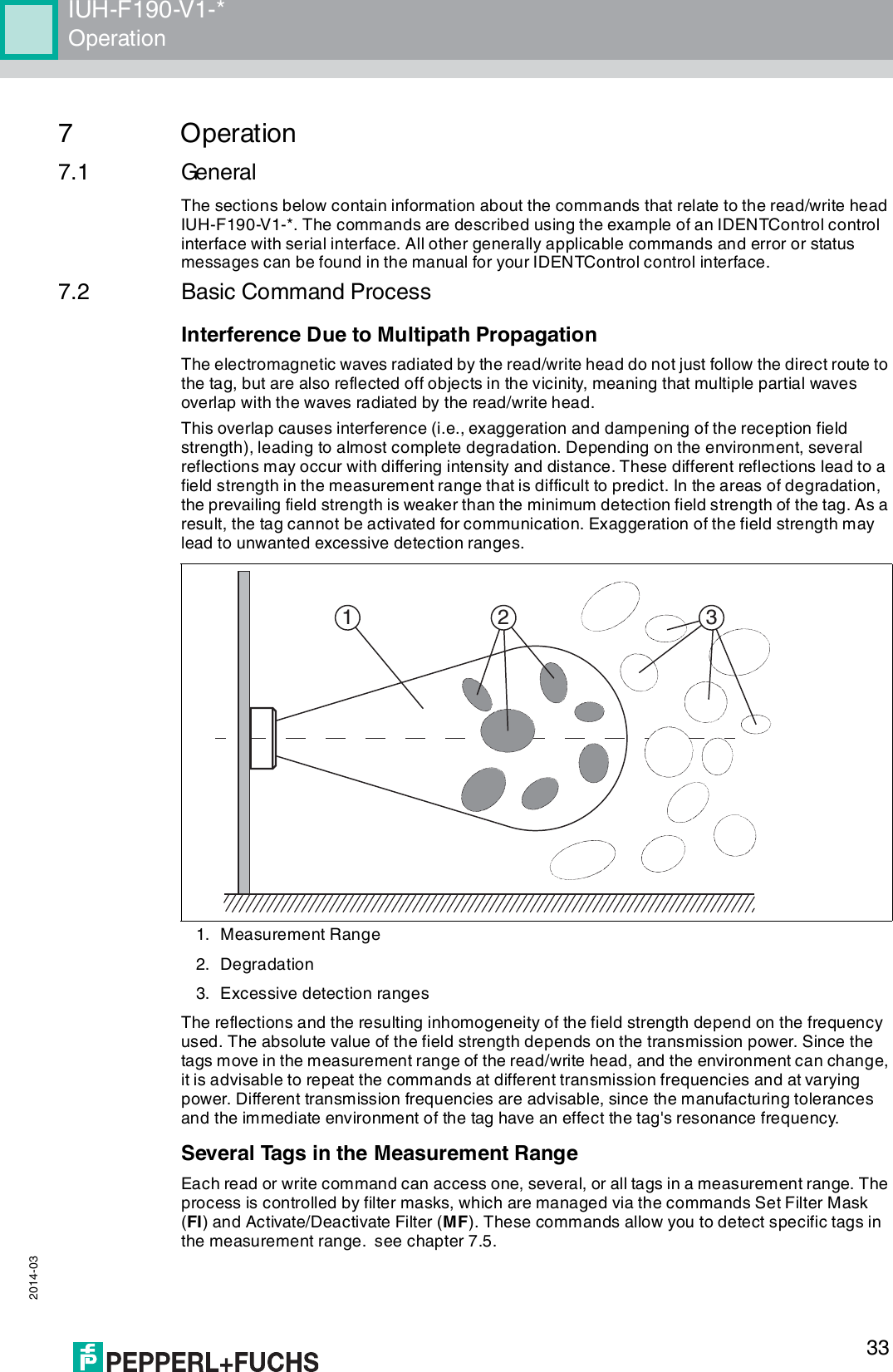
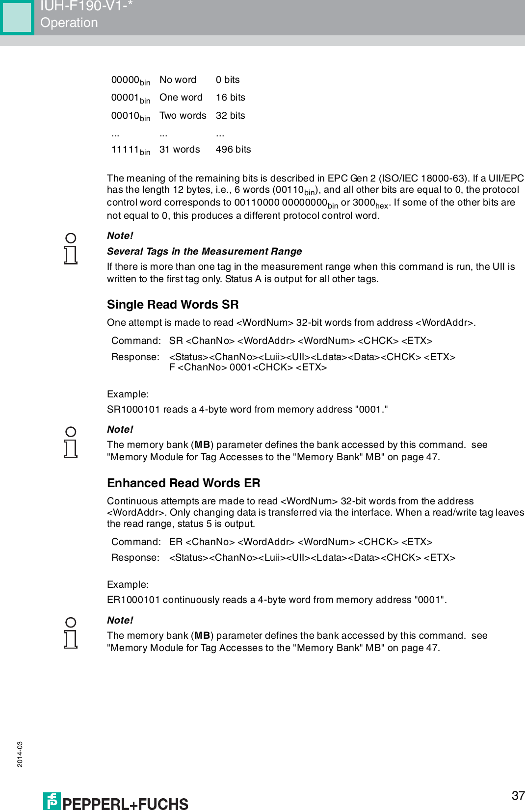
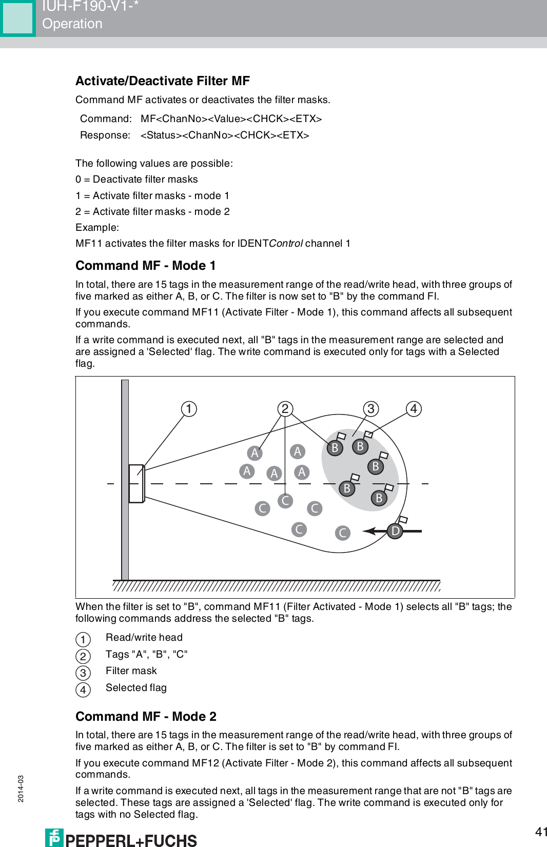
![IUH-F190-V1-*Appendix 2014-035910.3 ASCII table10.4 Measurement RangeThe read/write head has a typical detection range of around 1 meter; this range is determined by the tag used and can be adjusted by selecting the transmission power. Other influencing factors include the design/installation of the specific application, interference from any materials present (in particular metal), and the ambient conditions. The read and write distances for the relevant tag, which are detailed separately, have been established in a test laboratory under ideal conditions. For this reason, the combination of read/write head and tag must be tested for the intended application under real conditions.hex dec ASCII hex dec ASCII hex dec ASCII hex dec ASCII00 0NUL 20 32 Space 40 64 @60 96 '01 1SOH 21 33 !41 65 A61 97 a02 2STX 22 34 "42 66 B62 98 b03 3ETX 23 35 #43 67 C63 99 c04 4EOT 24 36 $44 68 D64 100 d05 5ENQ 25 37 %45 69 E65 101 e06 6ACK 26 38 &46 70 F66 102 f07 7BEL 27 39 '47 71 G67 103 g08 8BS 28 40 (48 72 H68 104 h09 9HT 29 41 )49 73 I69 105 I0A 10 LF 2A 42 *4A 74 J6A 106 j0B 11 VT 2B 43 +4B 75 K6B 107 k0C 12 FF 2C 44 ,4C 76 L6C 108 l0D 13 CR 2D 45 -4D 77 M6D 109 m0E 14 SO 2E 46 .4E 78 N6E 110 n0F 15 SI 2F 47 /4F 79 O6F 111 o10 16 DLE 30 48 050 80 P70 112 p11 17 DC1 31 49 151 81 Q71 113 q12 18 DC2 32 50 252 82 R72 114 r13 19 DC3 33 51 353 83 S73 115 s14 20 DC4 34 52 454 84 T74 116 t15 21 NAK 35 53 555 85 U75 117 u16 22 SYN 36 54 656 86 V76 118 v17 23 ETB 37 55 757 87 W77 119 w18 24 CAN 38 56 858 88 X78 120 x19 25 EM 39 57 959 89 Y79 121 y1A 26 SUB 3A 58 :5A 90 Z7A 122 z1B 27 ESC 3B 59 ;5B 91 [7B 123 {1C 28 FS 3C 60 <5C 92 \7C 124 |1D 29 GS 3D 61 =5D 93 ]7D 125 }1E 30 RS 3E 62 >5E 94 ^7E 126 ~1F 31 US 3F 63 ?5F 95 _7F 127 DEL](https://usermanual.wiki/Pepperl-Fuchs/IUH-F190-V1/User-Guide-2266324-Page-59.png)