Pepperl Fuchs IUH-F192-V1 UHF RFID read/write device User Manual IUH F192 V1
Pepperl + Fuchs Inc UHF RFID read/write device IUH F192 V1
UserManual.wiki
>
Pepperl Fuchs
>
IUH-F192-V1 User Manual
>
user manual 4140
Contents
1.
user manual 4140
2.
user manual 4881
user manual 4140
Navigation menu
Upload a User Manual
Namespaces
Wiki Guide
HTML
PDF
Info
Views
User Manual
Discussion / Help
Navigation
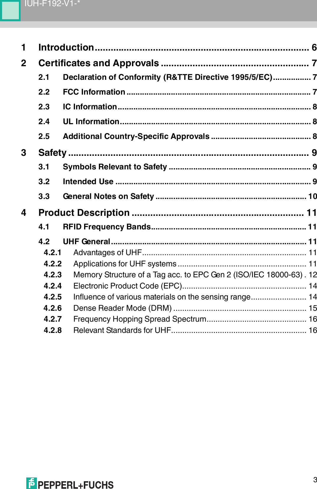
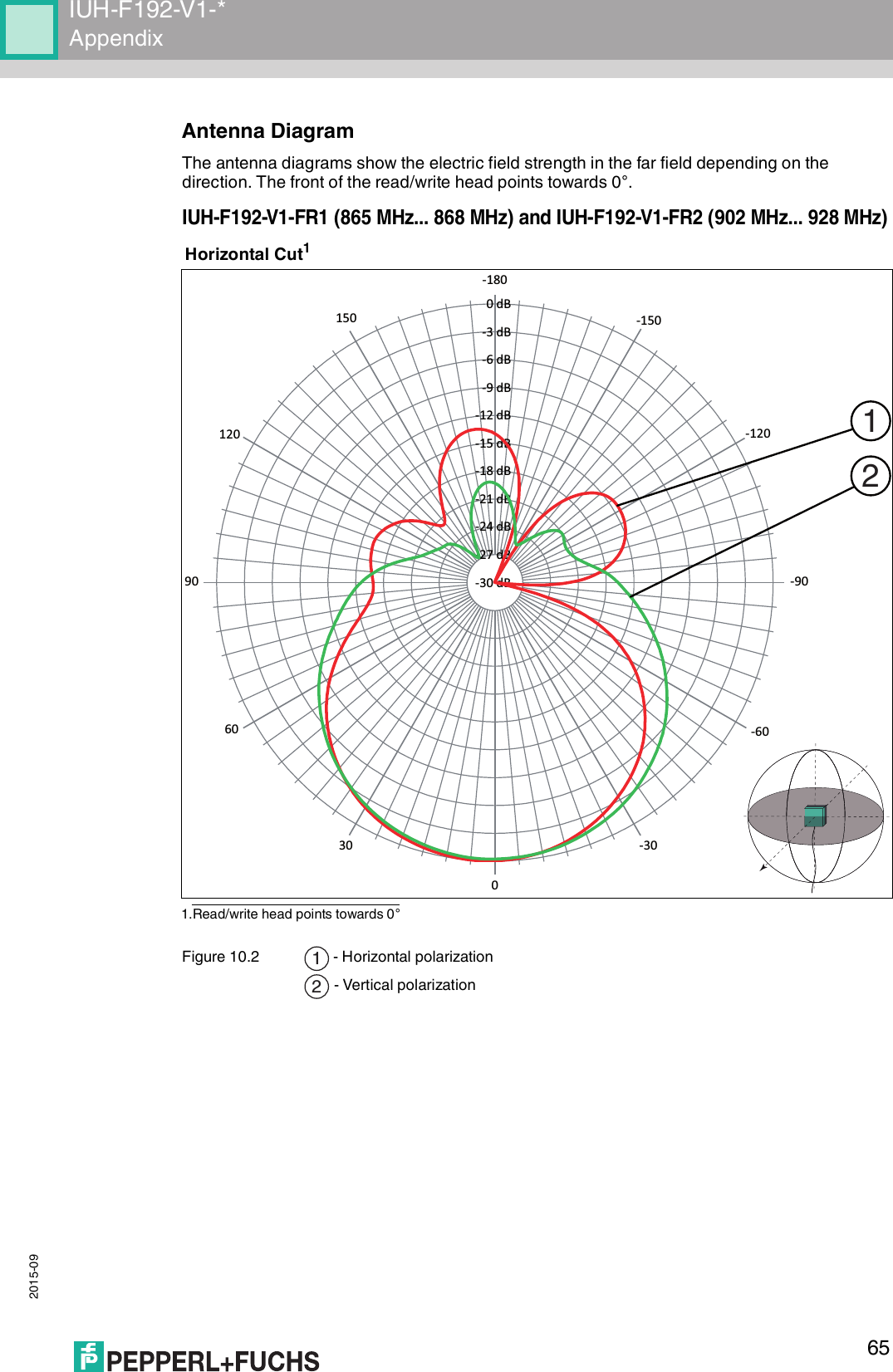
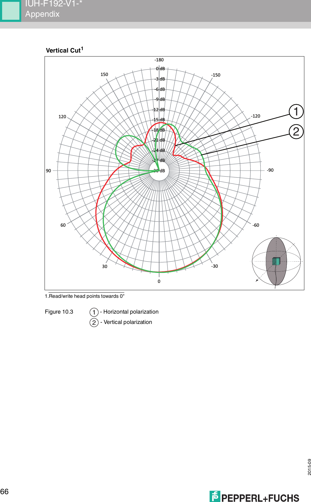
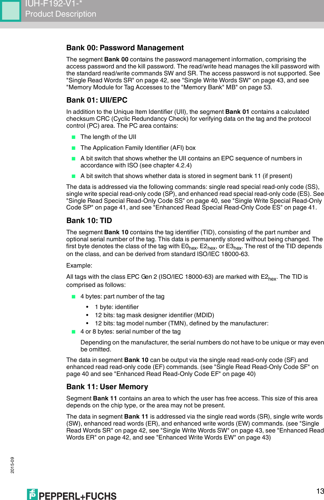
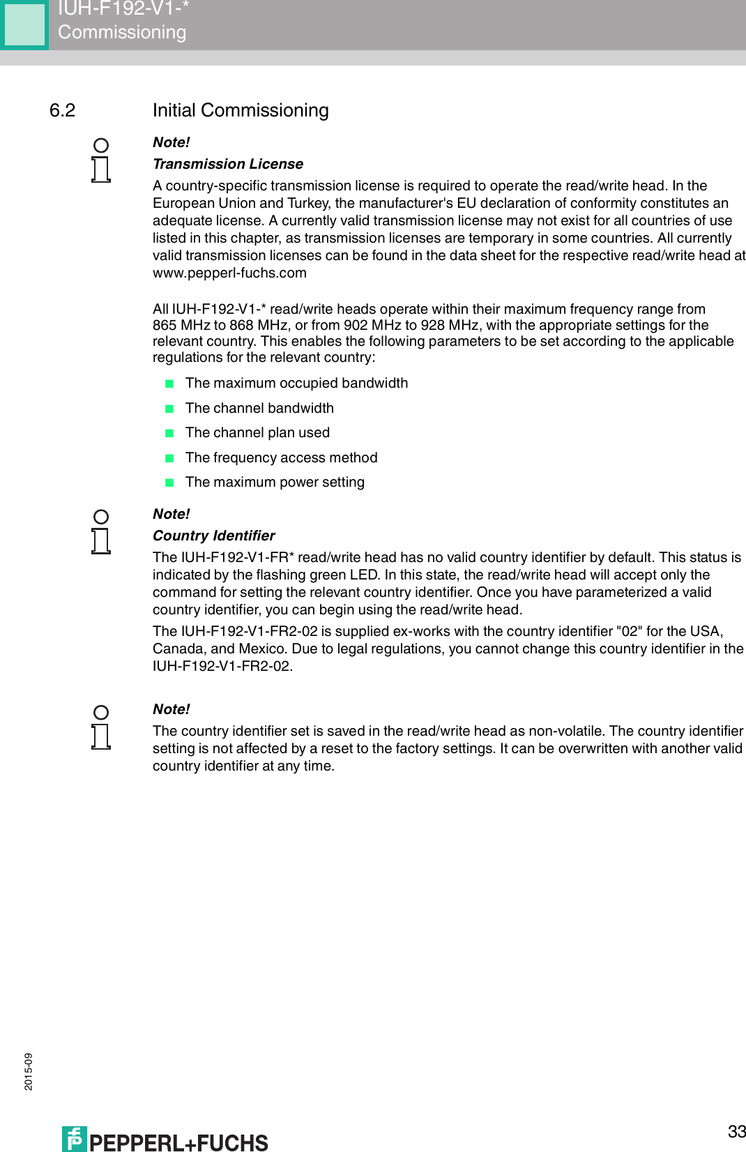
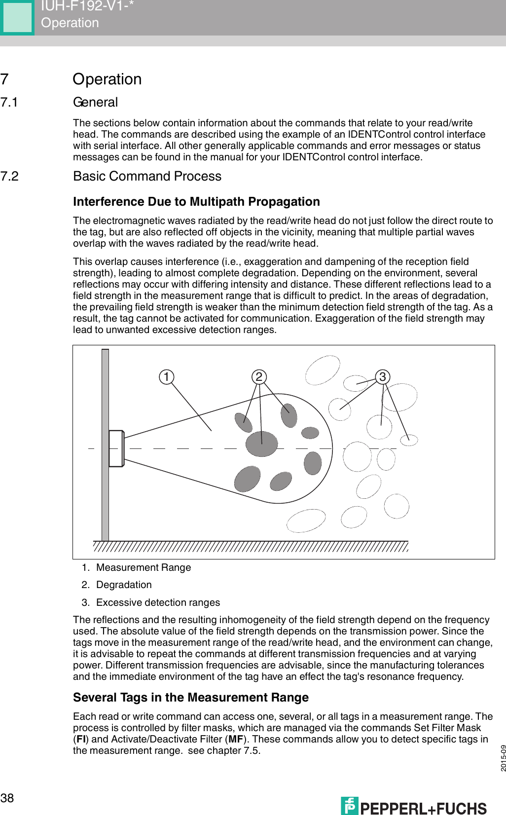
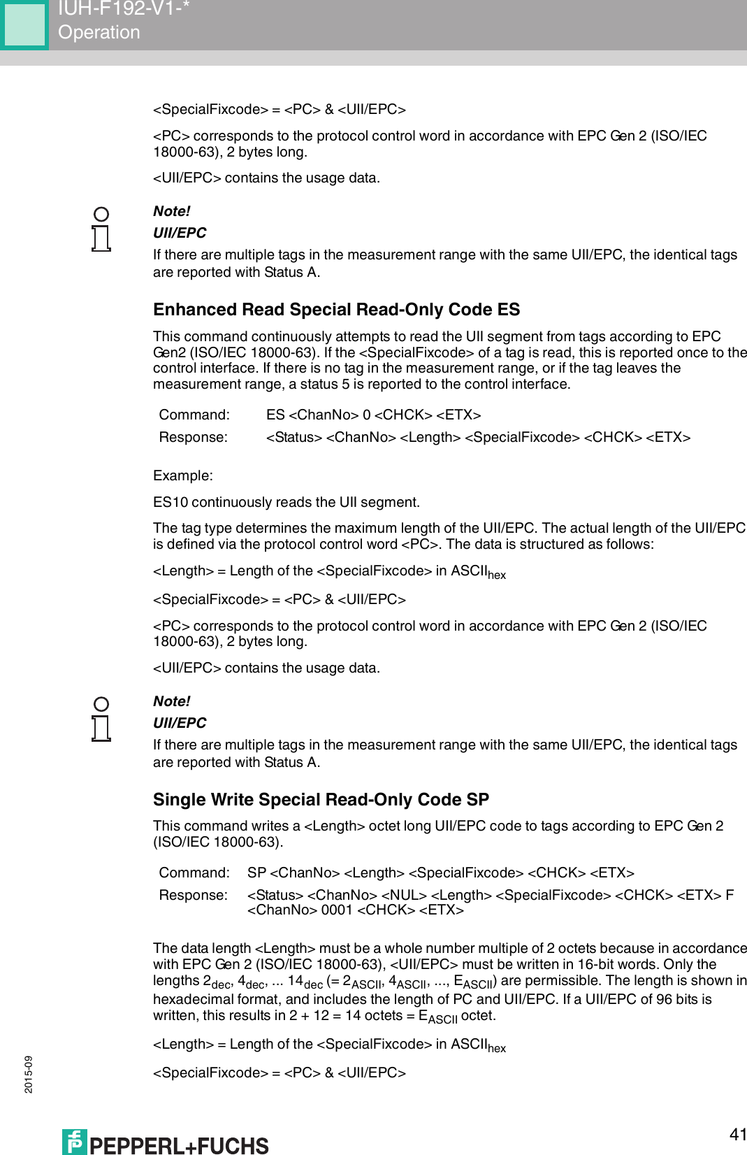
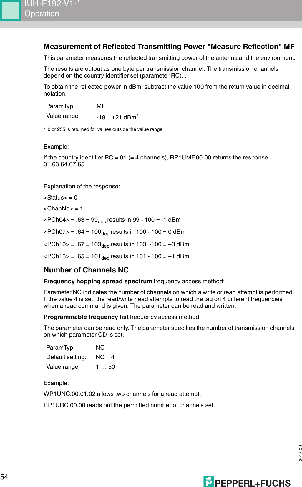
![IUH-F192-V1-*Product Description 2015-09114 Product Description4.1 RFID Frequency BandsThe following diagram shows the position of the different frequency bands used for RFID. The read/write heads described in this manual operate in the frequency range from 865 MHz ... 868 MHz and from 902 MHz ... 928 MHz, highlighted in color. ■100 kHz ... 135 kHz: Low frequency LF■13.56 MHz: High frequency HF■865 MHz ... 868 MHz (Europe), 902 MHz ... 928 MHz (USA), 920 MHz ... 925 MHz (China): ultra-high frequency UHF■2.45 GHz and 5.8 GHz: Microwave MW4.2 UHF General4.2.1 Advantages of UHF■Long detection range■UHF tags are available as cheap and space-saving adhesive labels■High transfer rates■Tag is available with a large working memory (user memory)■Bulk detection4.2.2 Applications for UHF systems■Identification in galvanic coating or painting systems used in automotive production,■Identification feasible over greater distances than with LF and HF systems,■Identification of automotive superstructures in automotive production,■Pallet identification and measurement of goods movements in the logistics sector, and■Access control at unloading stations with HGV identification.Frequency[MhZ]125 kHz2,45 GHz13,56 MHz5,8 GHz868/915 MHz0,1LF1 10HF100 1000UHF10000MW](https://usermanual.wiki/Pepperl-Fuchs/IUH-F192-V1.user-manual-4140/User-Guide-2775913-Page-11.png)
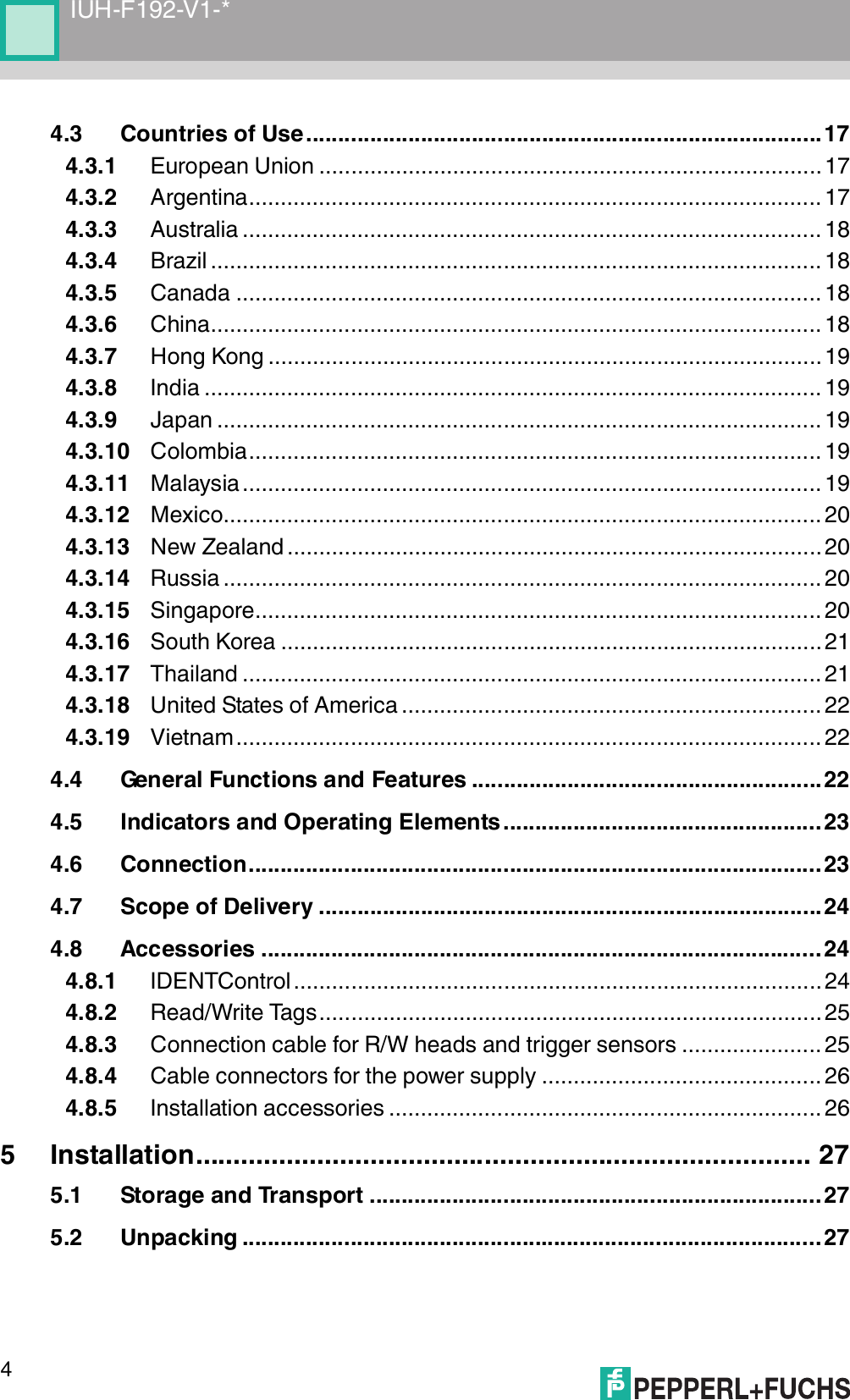
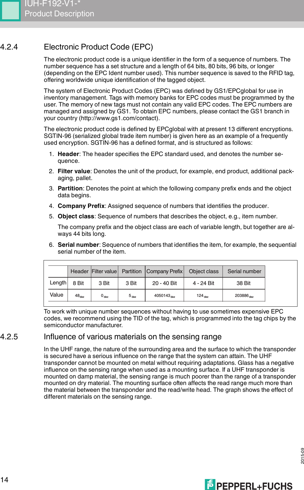
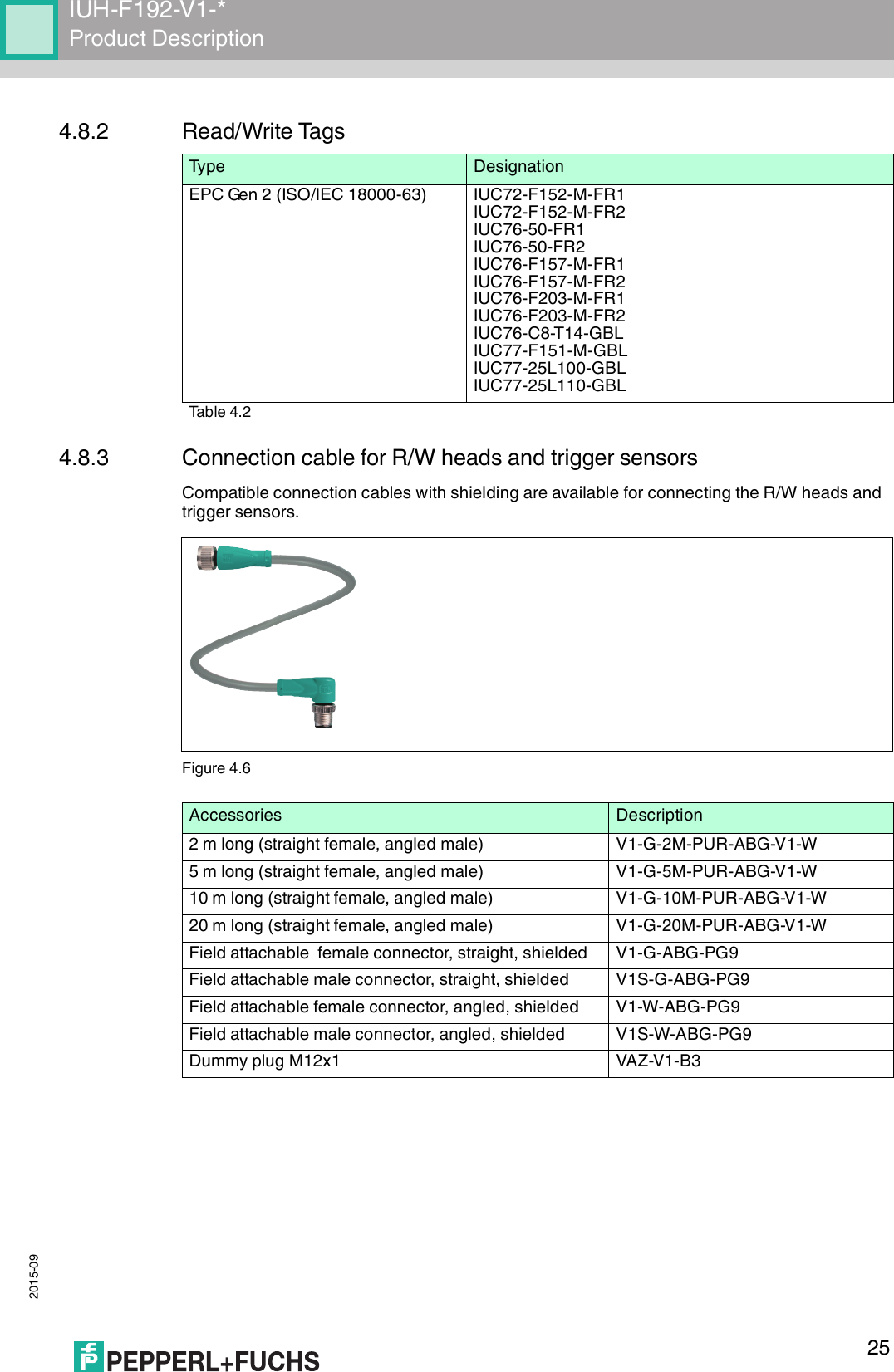
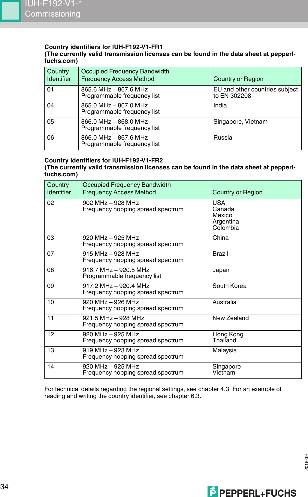
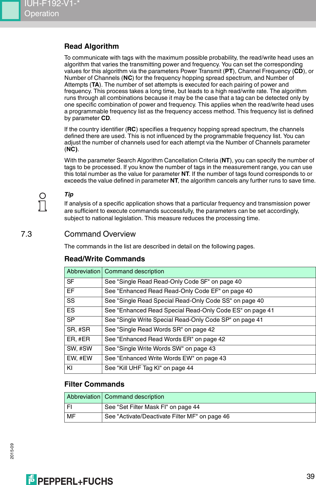
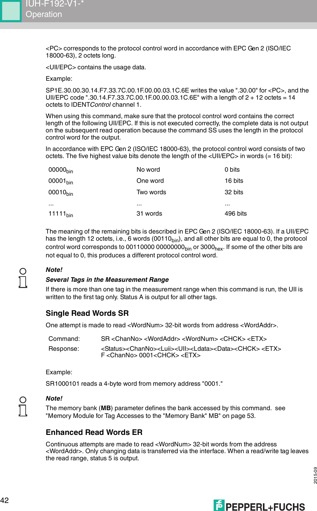
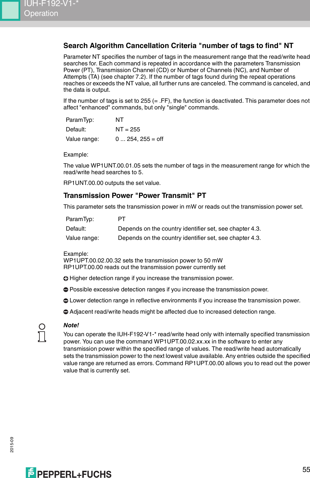
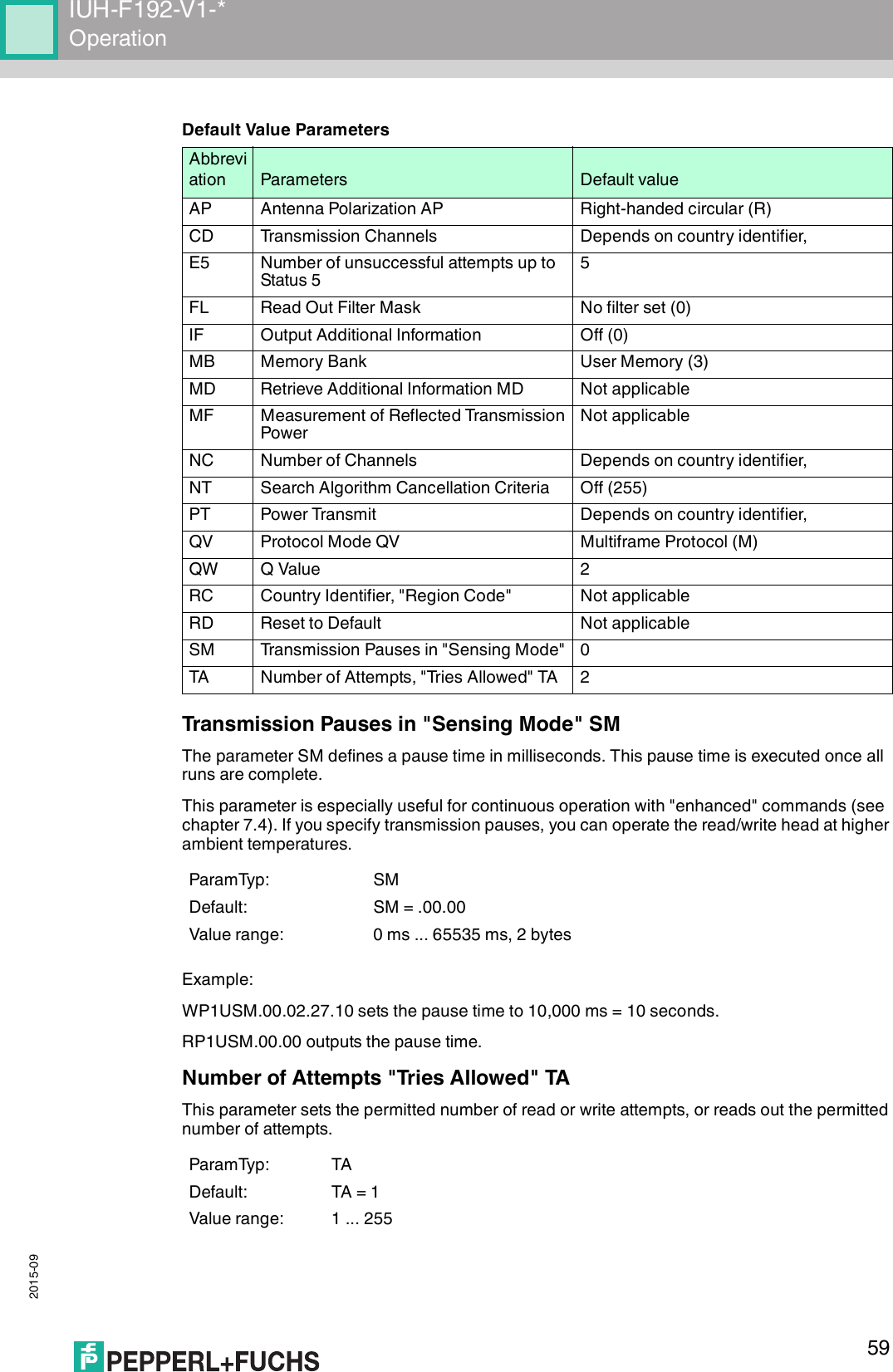
![2015-0912IUH-F192-V1-*Product Description4.2.3 Memory Structure of a Tag in Accordance with EPC Gen 2 (ISO/IEC 18000-63)The memory module of an EPC Gen 2 (ISO/IEC 18000-63) tag is split into four segments. The main contents of these segments are:Segment Function LengthBank 00(00bin = 0dec)Password managementDepending on the tag type, see table "Tag Types, UHF" on page 48/column "Bank 00"Bank 01(01bin = 1dec)Unique Item Identifier (UII)Electronic Product Code (EPC)Depending on the tag type, see table "Tag Types, UHF" on page 48/column "UII/EPC"Bank 10(10bin = 2dec)Tag ID (TID) 4 bytes (MDID, TMN) + 0, 4, or 8 bytesBank 11(11bin = 3dec)User memory Depending on the tag type, see table "Tag Types, UHF" on page 48/column "User Data"USERTIDUII/EPCRESERVEDRFU [7:0]10h1Fh...MSB LSBDSFID [7:0]00h0FhTID [15:0]10h1Fh...MSB LSBTID [31:16]00h0FhUII/EPC [N:N-15]20h210h2Fh...MSB LSBPC [15:0]10h1FhUII/EPC [15:0]CRC-16 [15:0]00h0FhAccess Password [15:0]30h3Fh...MSB LSBAccess Password [31:16]20h2FhKill Password [15:0]10h1FhKill Password [31:16]00h0FhBank 11Bank 10Bank 01Bank 00SR/ERSW/EWSS/ESSPSF/EF...Optional XPC_W2 [15:0]Optional XPC_W2 [15:0]...220h21Fh22FhMemory moduleCommandsRead / write head](https://usermanual.wiki/Pepperl-Fuchs/IUH-F192-V1.user-manual-4140/User-Guide-2775913-Page-12.png)
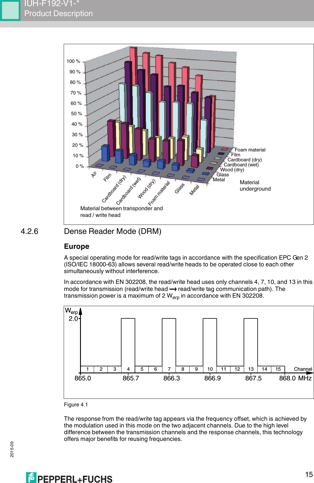
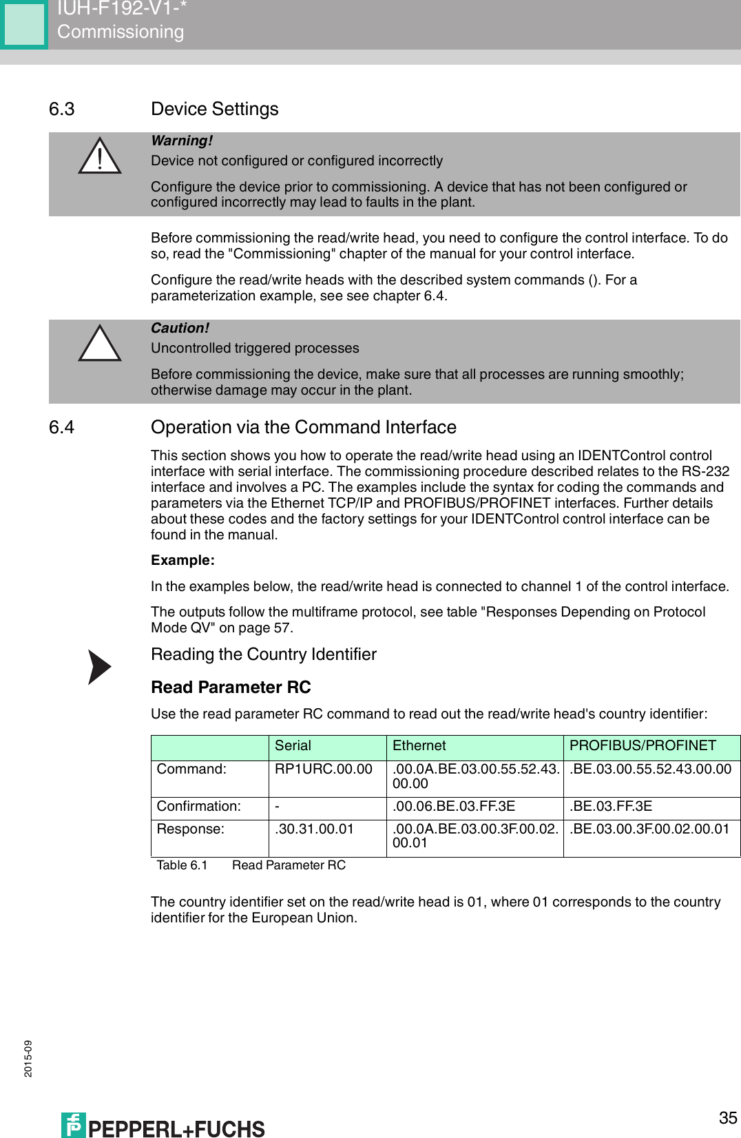
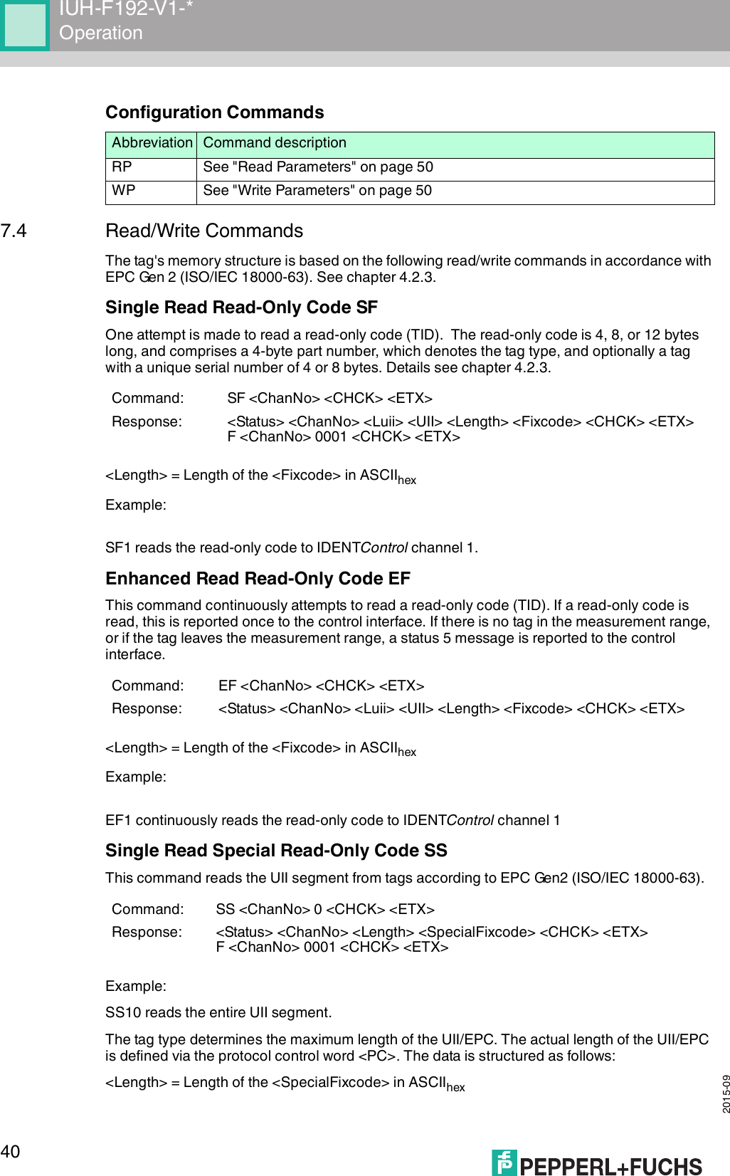
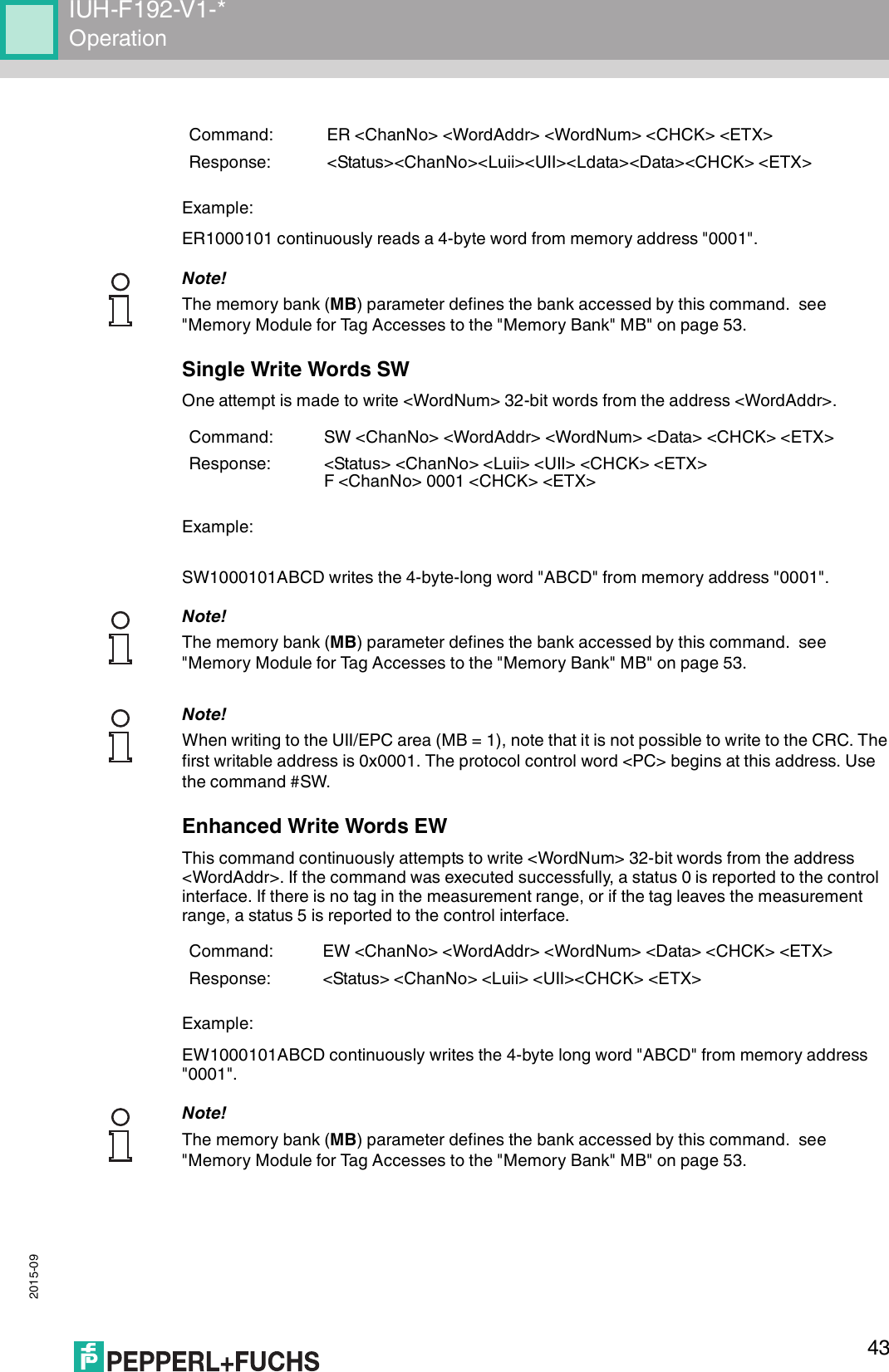
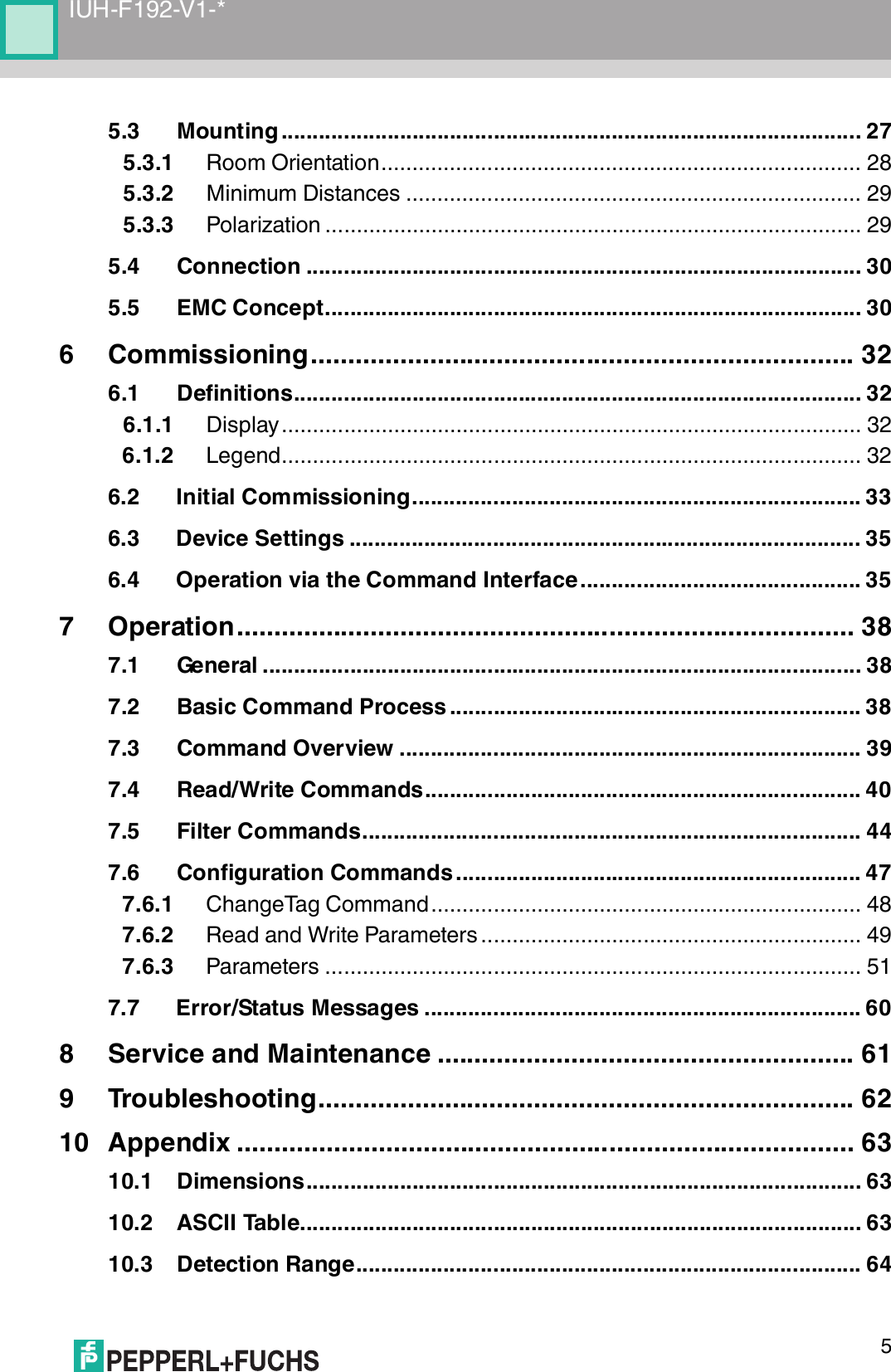
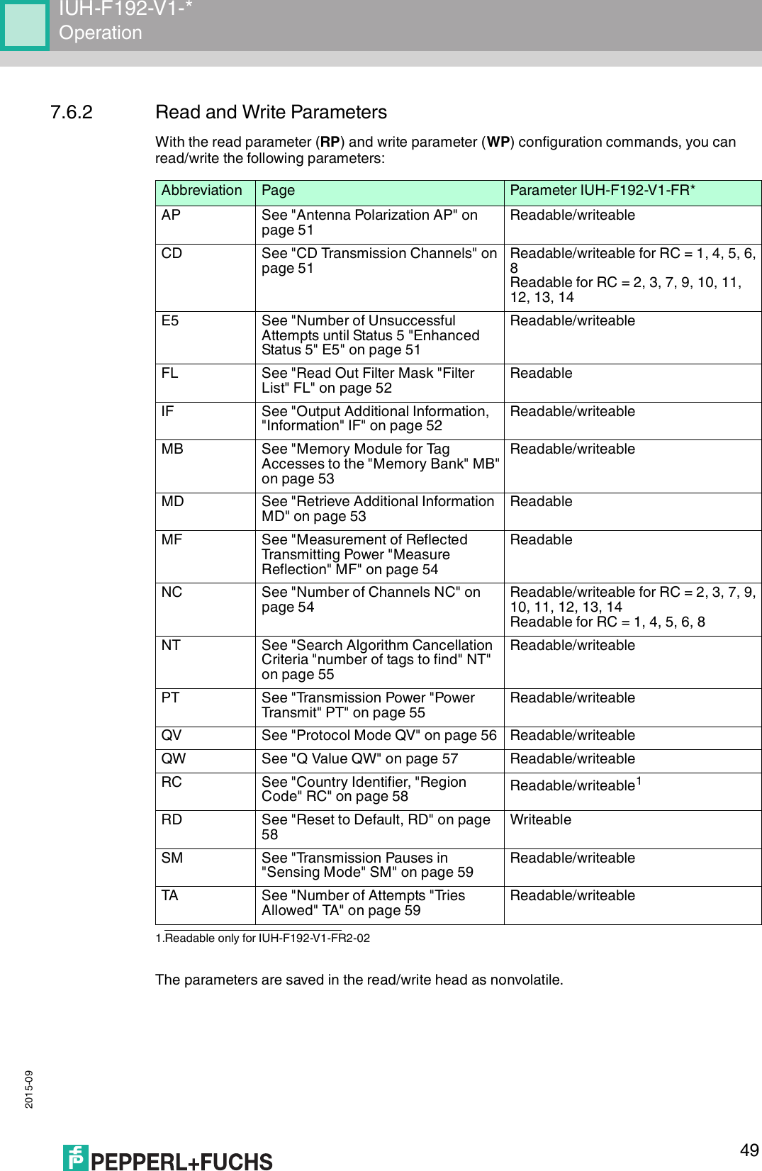
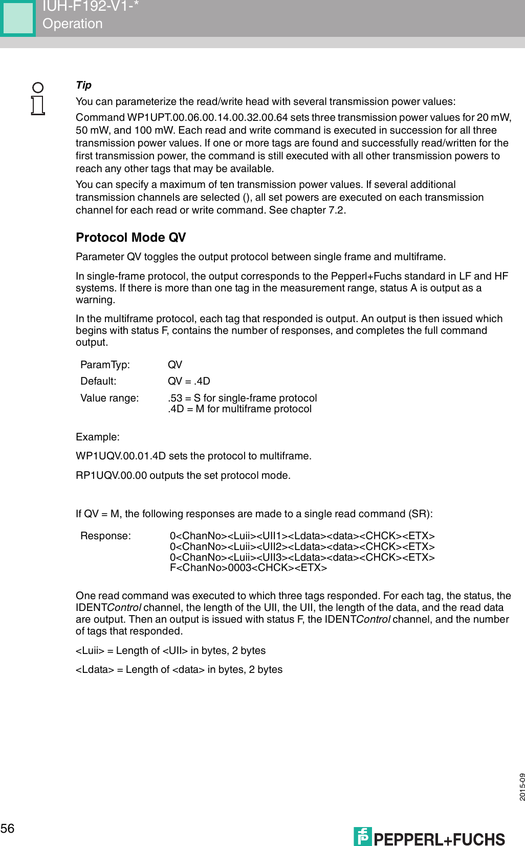
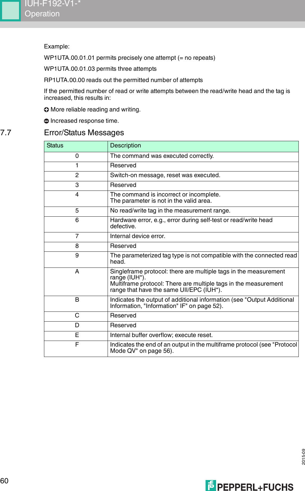
![2015-0948IUH-F192-V1-*Operation7.6.1 ChangeTag CommandThis command tells the R/W system with which tag type to communicate.Example:CT180 sets the tag type for IDENTControl channel 1 to IUC80CT180 sets a generally valid tag type, which allows the read-only code to be read out for each tag, and therefore provides information about the chip type of the tag.Tag Types, UHFCommand: CT <ChanNo> <TagType> <CHCK> <ETX>Response: <Status> <ChanNo> <CHCK> <ETX>Default: 80Note!The read/write head uses only tag type 80.Tag typeChip Pepperl+Fuchs desig-nationBank 00 [bit]UII/EPC [bit]TIDUser data [octet]Type Designation Type Unique?72 EPC Class 1 Gen 2NXP UCode-EPC-G2XMIUC72 32 + 32 240 E2006003hex + seq. no.Yes 6476 EPC Class 1 Gen 2Alien Higgs-3 IUC76 32 + 32 96 – 4802)E2003412hex + seq. no.Yes 8 – 642)77 EPC Class 1 Gen 2Impinj Monza 4QT IUC77 32 + 32 128 E2801105hex + seq. no.Yes 6478 EPC Class 1 Gen 2Impinj Monza 5 IUC78 32 + 32 128 E2801130hex + seq. no.Yes 479 EPC Class 1 Gen 2NXP UCode G2iM IUC79 32 + 32 256 E2800680Ahex + seq. no.Yes 6480 EPC Class 1 Gen 2Read/write tag conforms with Class 1 Gen 2IUC801) 1)E2xxxxxxhex + seq. no.1) 1)Table 7.1 Tag types1) = depending on the tag type2) = EPC expandable to max. 480 bits. If a 480 bit EPC format is used, the user data is reduced from 64 octets to 8 octets.4](https://usermanual.wiki/Pepperl-Fuchs/IUH-F192-V1.user-manual-4140/User-Guide-2775913-Page-48.png)
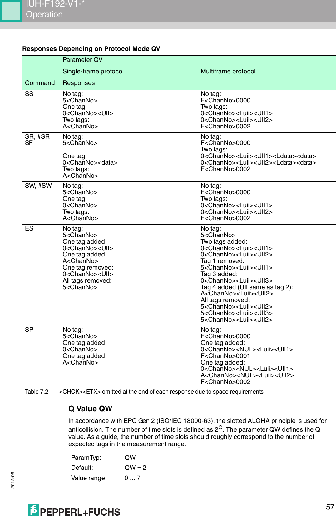
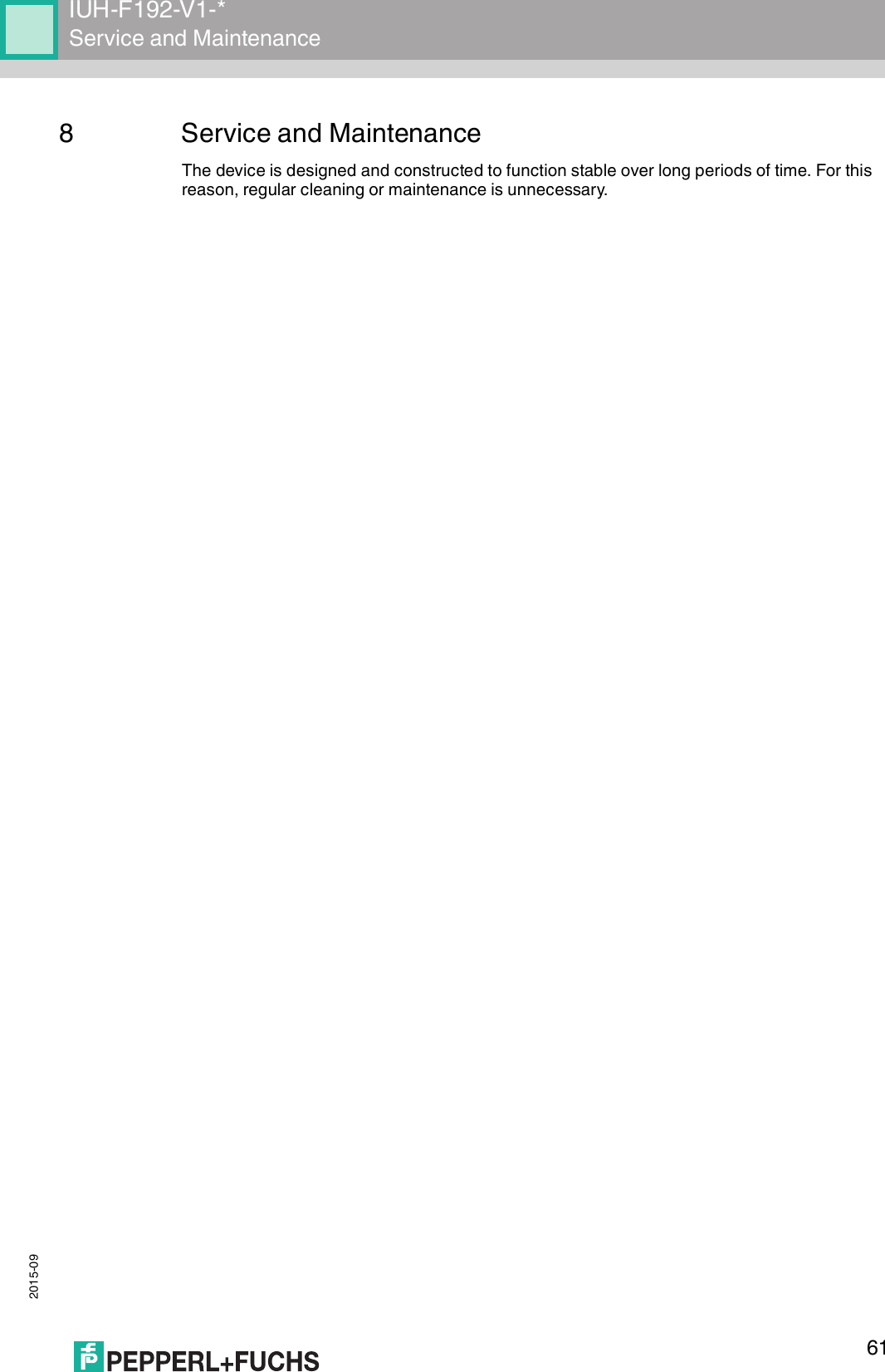
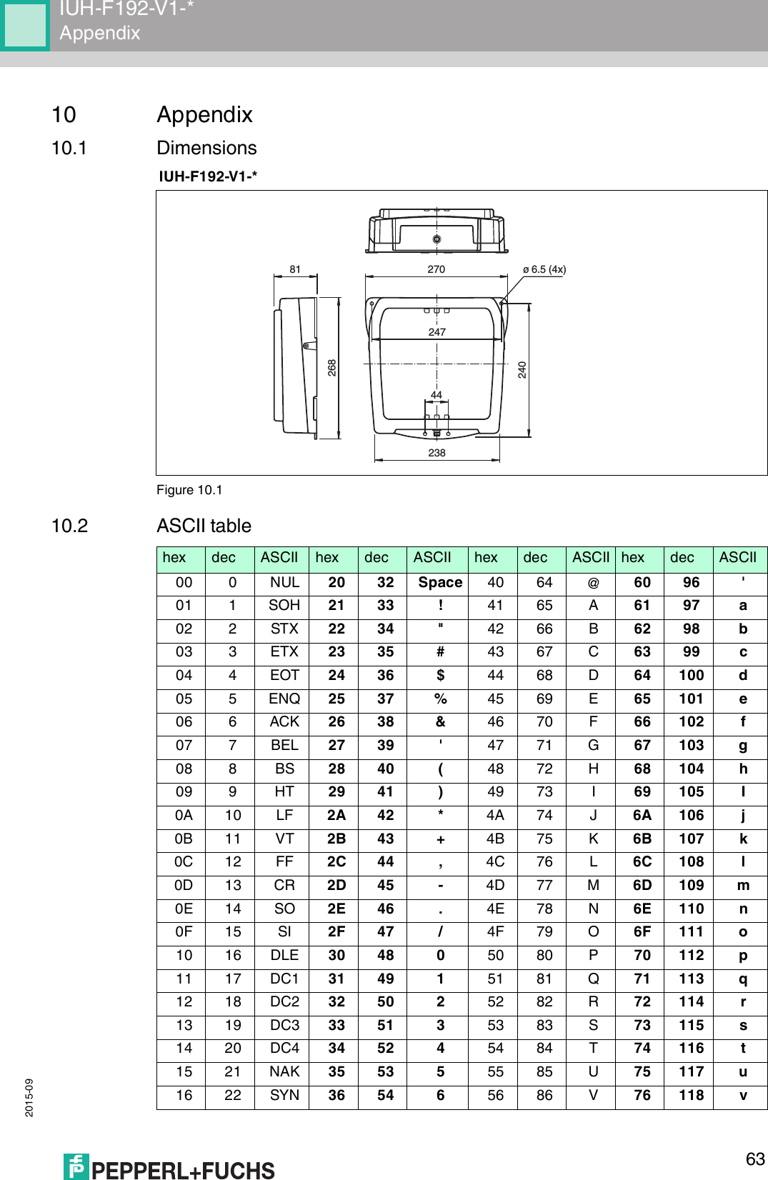
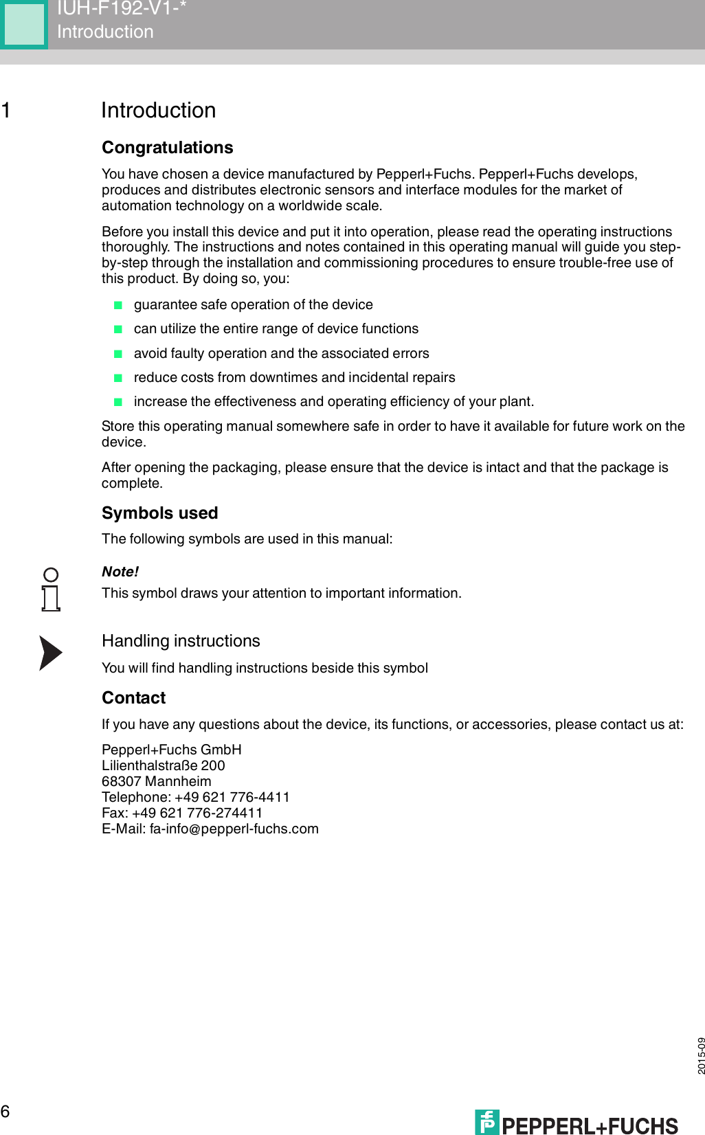
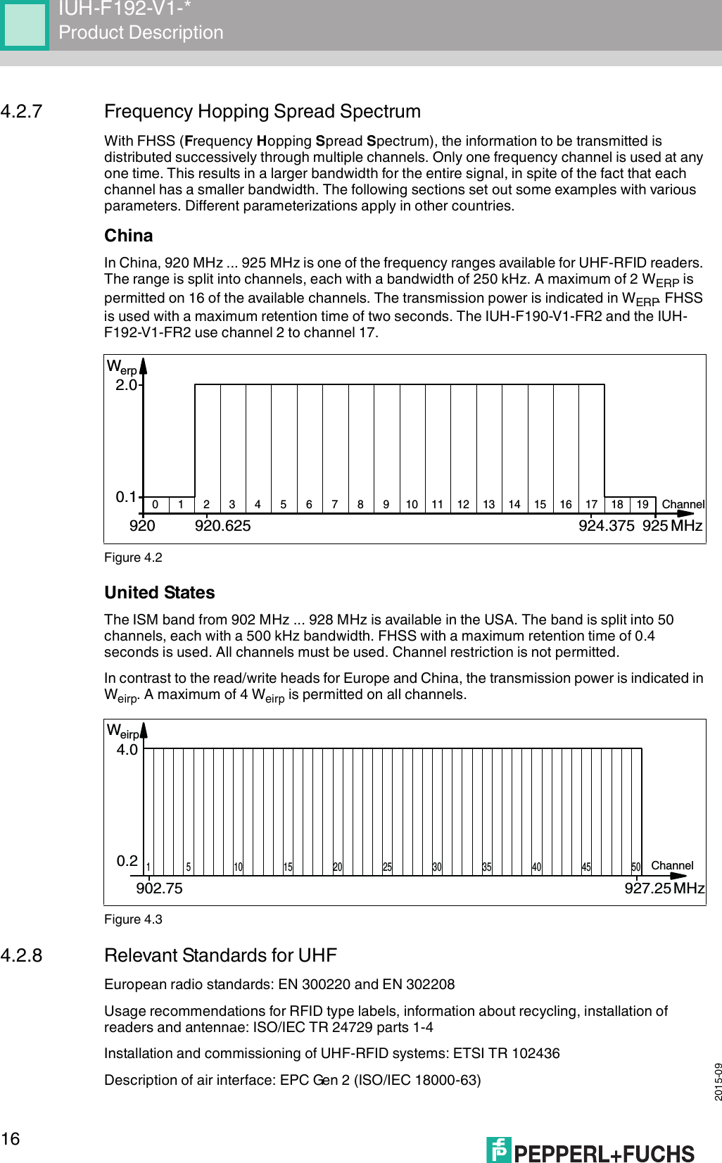
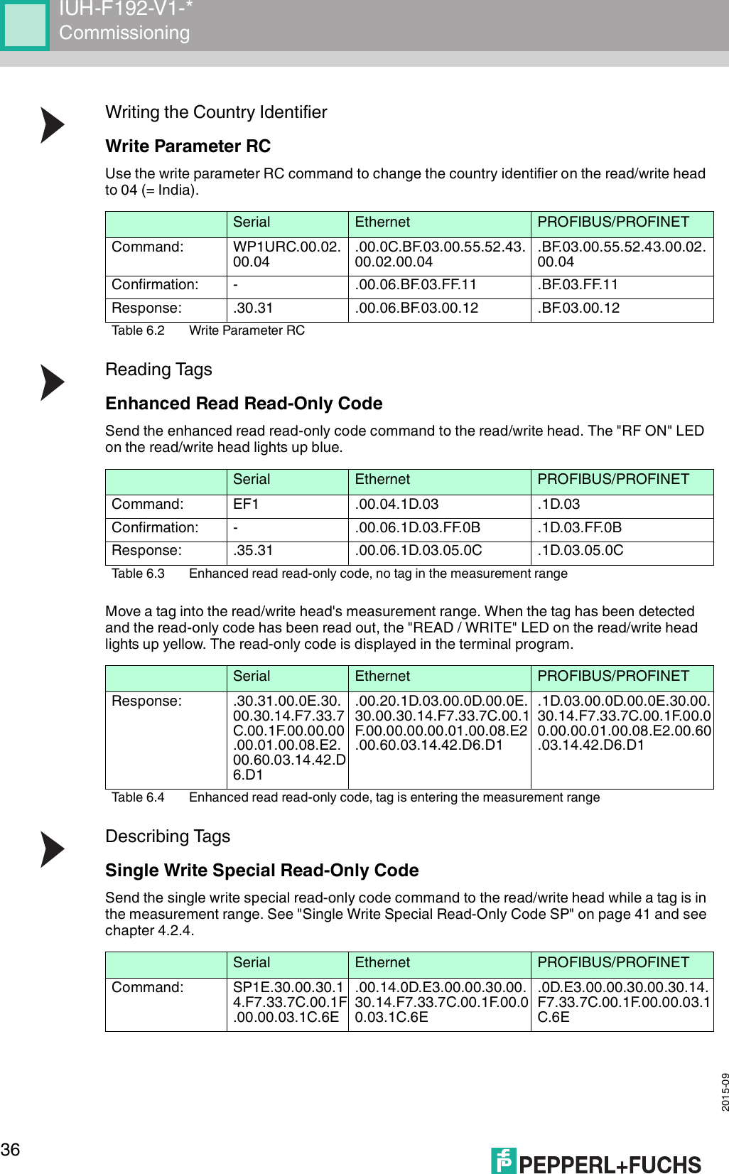
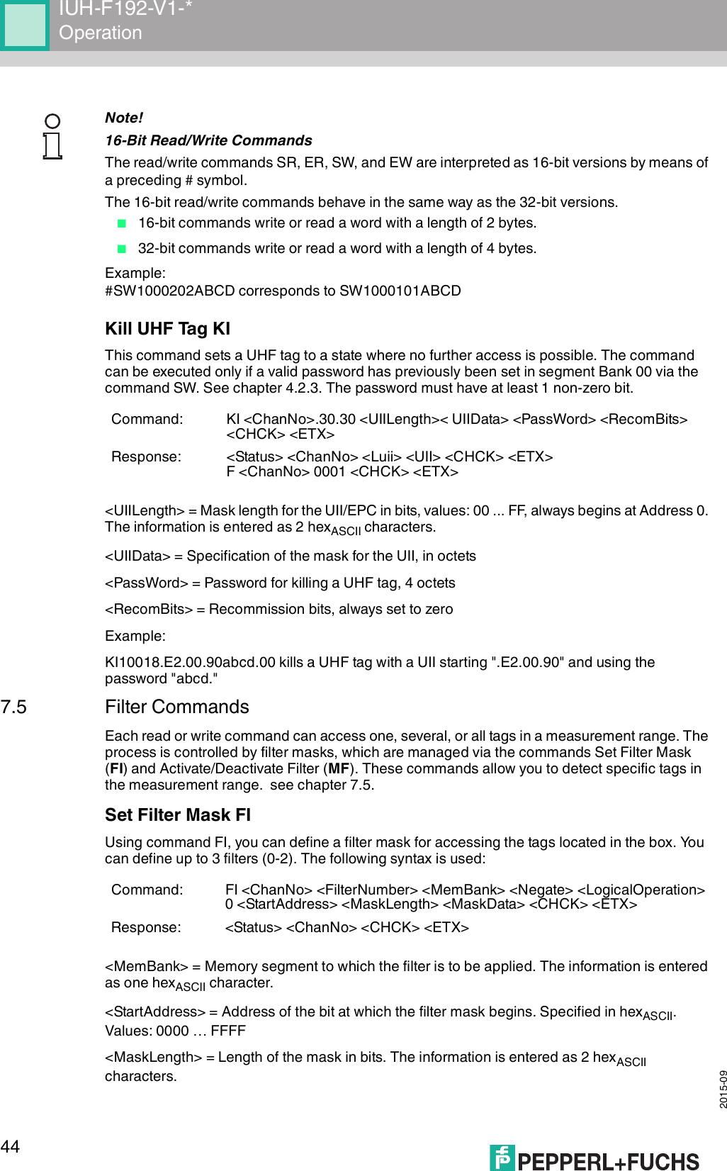
![2015-0964IUH-F192-V1-*Appendix10.3 Detection RangeThe read/write head has a typical detection range of around 1 meter; this range is determined by the tag used and can be adjusted by selecting the transmission power. Other influencing factors include the setup and installation of the specific application, interference from any materials present (in particular metal), and the ambient conditions. The read and write distances for the relevant tag, which are detailed separately, have been established in a test laboratory under ideal conditions. For this reason, the combination of read/write head and tag must be tested for the intended application under real conditions.Please note the distance tables. The distance tables and additional information regarding your product can be found at http://www.pepperl-fuchs.com. Simply enter the product name or model number in the Search box and then click the Search key.Select your product from the list of search results. Click on the information you require in the product information list, e.g., Technical documents.A list of all available documents is displayed.17 23 ETB 37 55 7 57 87 W 77 119 w18 24 CAN 38 56 8 58 88 X 78 120 x19 25 EM 39 57 9 59 89 Y 79 121 y1A 26 SUB 3A 58 : 5A 90 Z 7A 122 z1B 27 ESC 3B 59 ; 5B 91 [ 7B 123 {1C 28 FS 3C 60 < 5C 92 \ 7C 124 |1D 29 GS 3D 61 = 5D 93 ] 7D 125 }1E 30 RS 3E 62 > 5E 94 ^ 7E 126 ~1F 31 US 3F 63 ? 5F 95 _ 7F 127 DELhex dec ASCII hex dec ASCII hex dec ASCII hex dec ASCII](https://usermanual.wiki/Pepperl-Fuchs/IUH-F192-V1.user-manual-4140/User-Guide-2775913-Page-64.png)