PerComm 1005 Reflex Telemetry Device, OMNIDATA User Manual Usr Manual
PerComm Inc Reflex Telemetry Device, OMNIDATA Usr Manual
UserManual.wiki
>
PerComm
>
1005 User Manual
>
Usr Manual
Contents
1.
Usr Manual
2.
Updated user manual
Usr Manual
Navigation menu
Upload a User Manual
Namespaces
Wiki Guide
HTML
PDF
Info
Views
User Manual
Discussion / Help
Navigation
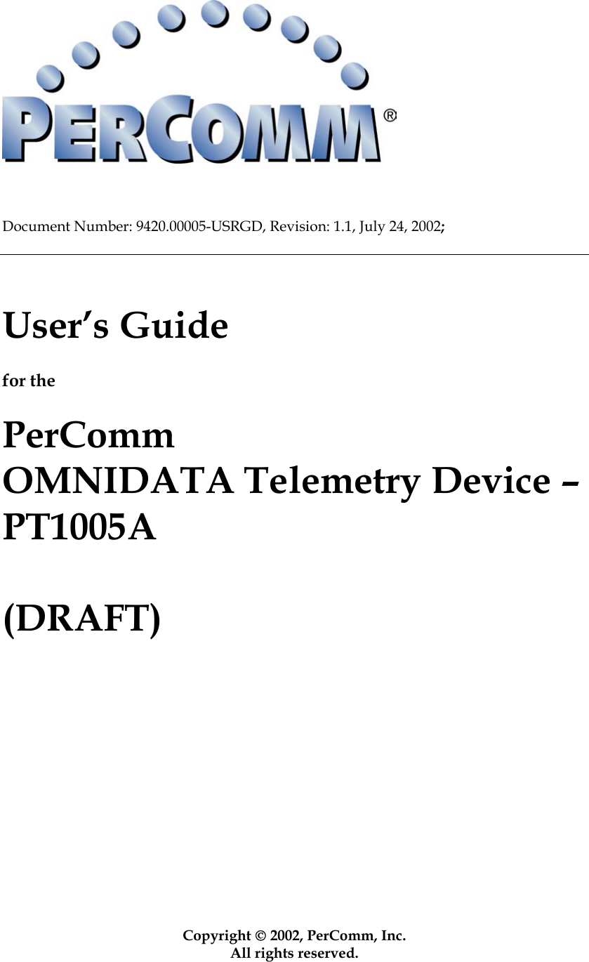
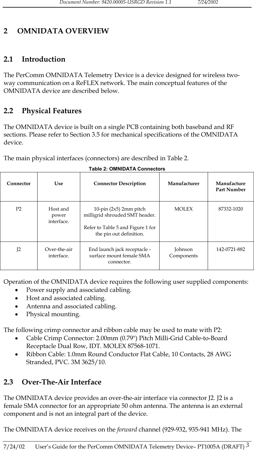
![Document Number: 9420.00005-USRGD Revision 1.1 7/24/2002 OMNIDATA, HCI and the PerComm logo are trademarks or registered trademarks of PerComm, Inc. ReFLEX, FLEXsuite and CLP are trademarks or registered trademarks of Motorola, Inc. 1.5 Safety The installation and operation of the products described in this document may present unsafe conditions that may result in equipment damage, personal injury or death. Read all instructions before using the products described. The procedures described should be performed by qualified personnel only. Follow all safety guidelines including reasonable judgment. Do not proceed if there is any doubt regarding procedures, contact PerComm Technical support (see Section 1.3). Failure to follow safety guidelines could result in equipment damage, personal injury or death. 1.6 References Refer to Table 1 for a list of referenced documents. Table 1: Reference Documents Document Reference Document Title Document Number [1] ReFLEX Protocol Specification Document – Version 2.7.1.1 Motorola 68P81139B02-B [2] HCI Interface Specification – Version 1.9 PerComm 9420.00005-IRS [3] Communication Linking Protocol (CLPTM) Serial Interface – Reference Manual – ReFLEX 25 and 50 Technology Motorola 6881033B20 [4] FLEXsuite of Enabling Protocols Specification Document – Version 2.1.1 Motorola 6881139B10 7/24/02 User’s Guide for the PerComm OMNIDATA Telemetry Device– PT1005A (DRAFT) 2](https://usermanual.wiki/PerComm/1005.Usr-Manual/User-Guide-267584-Page-5.png)
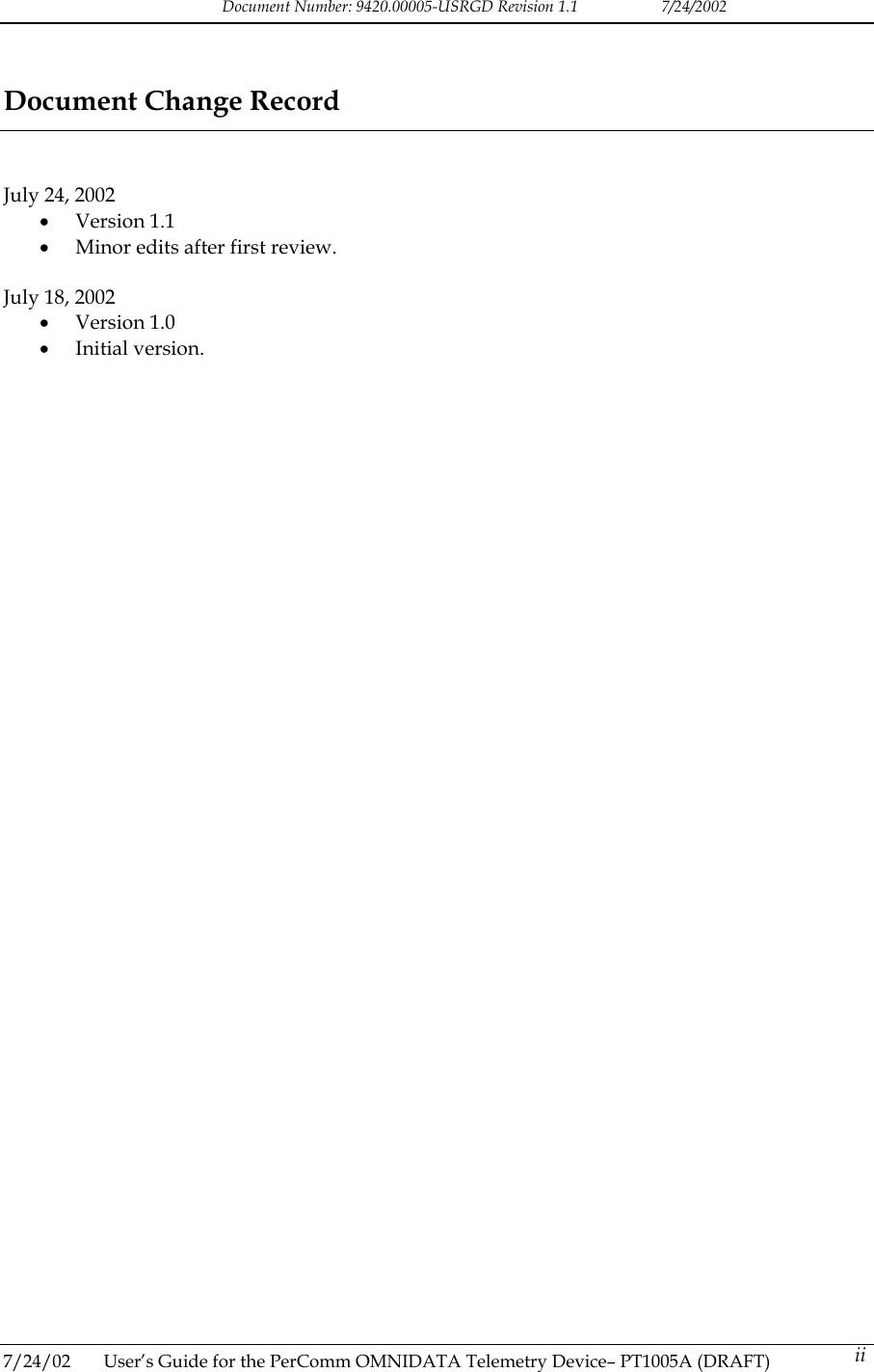
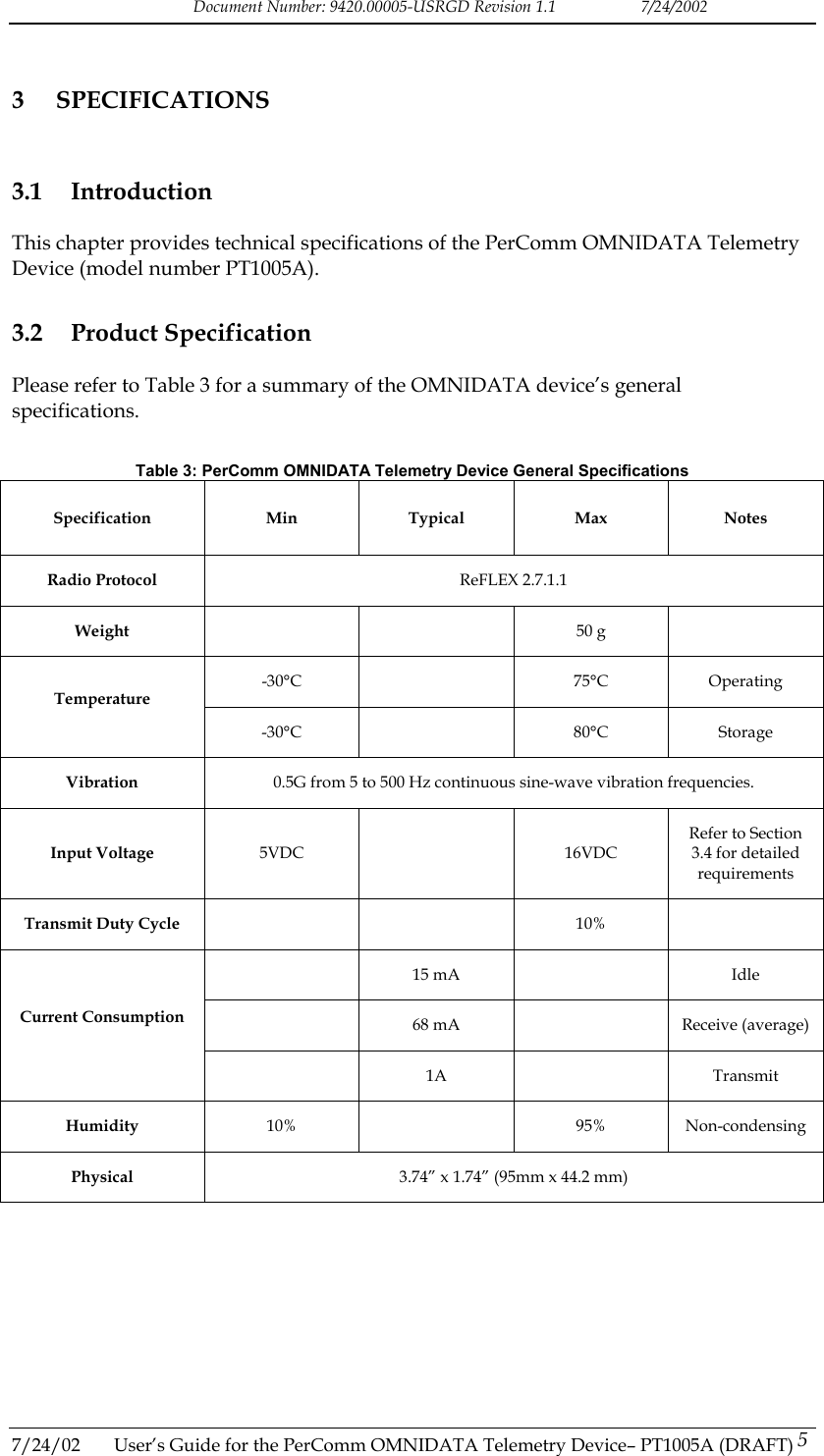
![Document Number: 9420.00005-USRGD Revision 1.1 7/24/2002 OMNIDATA device transmits on the reverse channel (896-902 MHz). The receiver and transmitter are driven by a ReFLEX 2.7.1.1 protocol stack. 2.4 ReFLEX 2.7.1.1 Protocol Stack The OMNIDATA device features a ReFLEX 2.7.1.1 protocol stack. The protocol stack contains all functionality required to register and operate on the ReFLEX network. The protocol stack is also compatible with ReFLEX 25 networks. 2.5 Host Interface The OMNIDATA device provides a host interface via connector P2. The host itself is an external entity and is not considered an integral part of the device. The host interface allows a host to perform the following functions: • Sending ReFLEX messages through the OMNIDATA device. • Receiving ReFLEX messages through the OMNIDATA device. • Monitoring the OMNIDATA device. • Controlling the OMNIDATA device. • Configuring the OMNIDATA device. • Updating the embedded software in the OMNIDATA device. The OMNIDATA device supports multiple host interface protocols including HCI [2] and CLP [3]. 2.6 FLEXsuite Encoder FLEXsuite [4] is a set of protocols used to encode messages on ReFLEX networks. The OMNIDATA device provides a built in FLEXsuite UAR encoder when using the HCI host interface protocol. Alternatively, the host can also perform its own FLEXsuite encoding. 2.7 Configurable Database The OMNIDATA device contains a FLASH based database of critical parameters. The database has been configured by your service provider. Please contact your service provider for any questions regarding the device configuration. 2.8 Embedded Software Many of the OMNIDATA features including the ReFLEX protocol stack are implemented in the device’s embedded software. The device has been programmed with the most up-to-date software at the time of manufacture. Please contact your service provider for any questions regarding updated software. 2.9 Power Input 7/24/02 User’s Guide for the PerComm OMNIDATA Telemetry Device– PT1005A (DRAFT) 4 Power is provided to the OMNIDATA device via connector P2. Refer to Section 3.3 for the P2 connector pin out. Refer to Section 3.4 for power supply requirements.](https://usermanual.wiki/PerComm/1005.Usr-Manual/User-Guide-267584-Page-7.png)
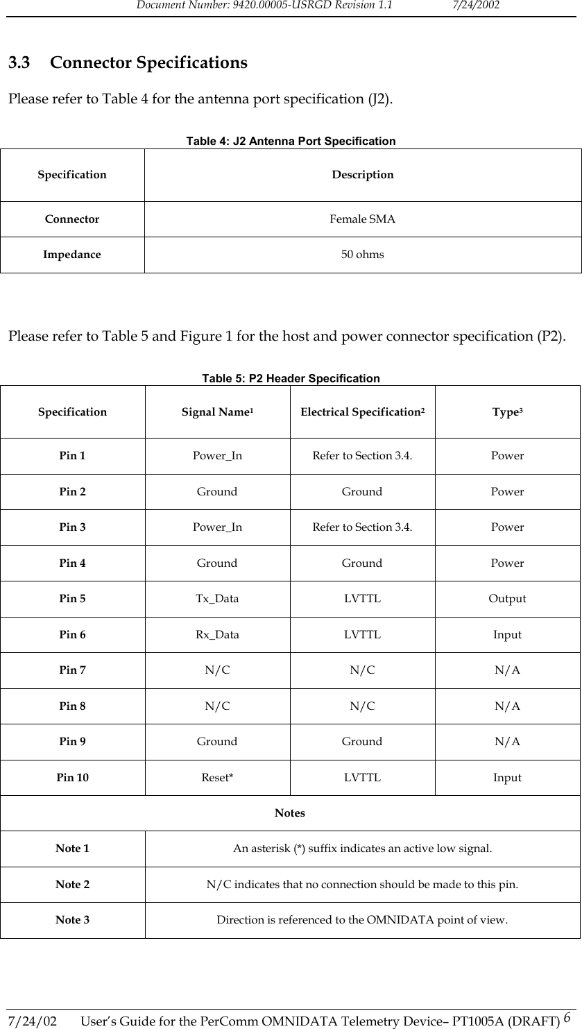
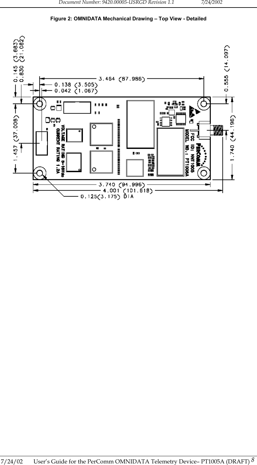
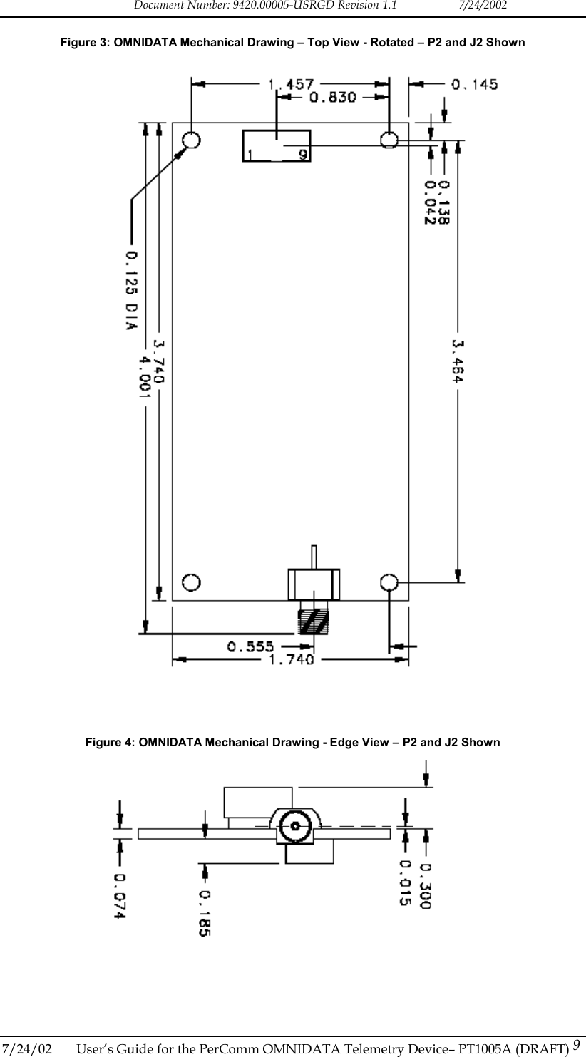
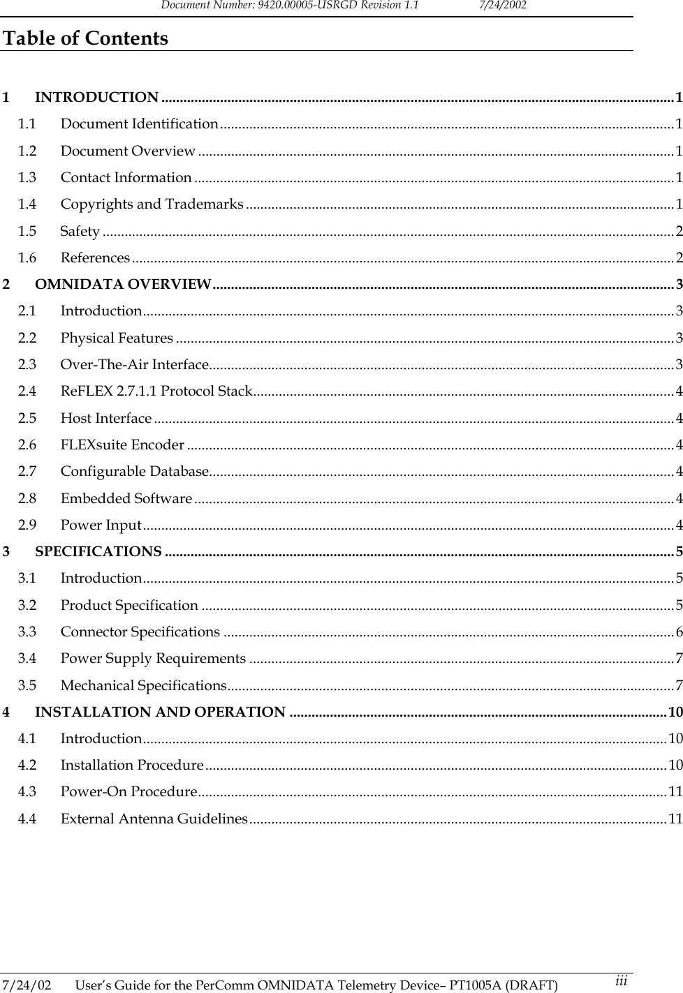
![Document Number: 9420.00005-USRGD Revision 1.1 7/24/2002 4 INSTALLATION AND OPERATION 4.1 Introduction This chapter provides guidelines and procedures for correct installation and operation of the PerComm OMNIDATA Telemetry Device. 4.2 Installation Procedure Follow the procedure outlined below to install the OMNIDATA device. 1. Select an appropriate installation setting. The installation setting must observe the guidelines listed below. Failure to comply with these guidelines may cause the OMNIDATA device to operate improperly. • The external antenna must be mounted in a location such that no person will ever come within 12 inches of the antenna. This is required to comply with FCC RF hazard regulations. • The device should be installed far from any switch mode power supply or digital switching circuitry. • The power supply should conform to requirements identified in Section 3.4. • The device should not be subject to permanent vibrations. • The device should not be subject to high magnetic fields. • The device should be mounted in such a way that it makes no contact, or it is not very close to any metallic object even if that object is connected to the ground. There should be no other electrical contact to anything other than the antenna and the flat cable for the power supply and host interface. 2. Install the OMNIDATA device using appropriate standoffs (e.g. Richco part number LMSP-4-01). Ensure that sufficient space is available to connect the antenna cabling, host cabling and power supply cabling. Mechanical drawings of the OMNIDATA device are shown in Section 3.5 to assist in this process. 3. Install the external antenna. The antenna must be installed in such a way that the main radiation pattern generates vertical polarization. Connect the antenna to the OMNIDATA device’s SMA antenna port. The antenna must conform to guidelines given in Section 4.3. 4. Install the host and power supply. Connect the host to the OMNIDATA device’s host interface header. The host must conform to the following guidelines: • The host supports the pin out specified in Table 5. • The power supply must conform to the specifications identified in Section 2.9. • The host implements a supported host interface protocol (HCI [4] or CLP [5].) Contact your service provider to determine which protocol is enabled on your OMNIDATA device. 7/24/02 User’s Guide for the PerComm OMNIDATA Telemetry Device– PT1005A (DRAFT) 10](https://usermanual.wiki/PerComm/1005.Usr-Manual/User-Guide-267584-Page-13.png)
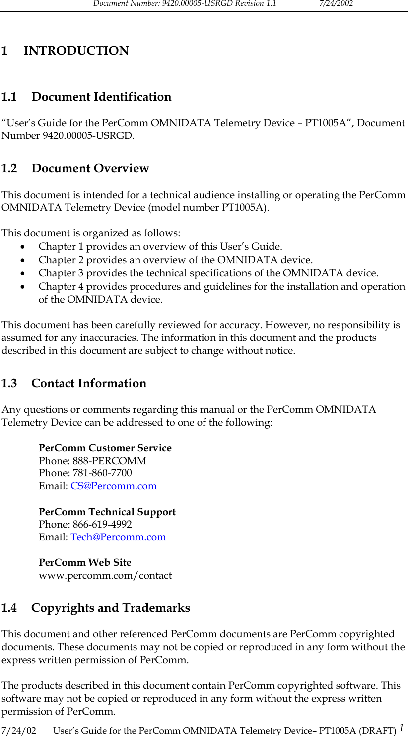
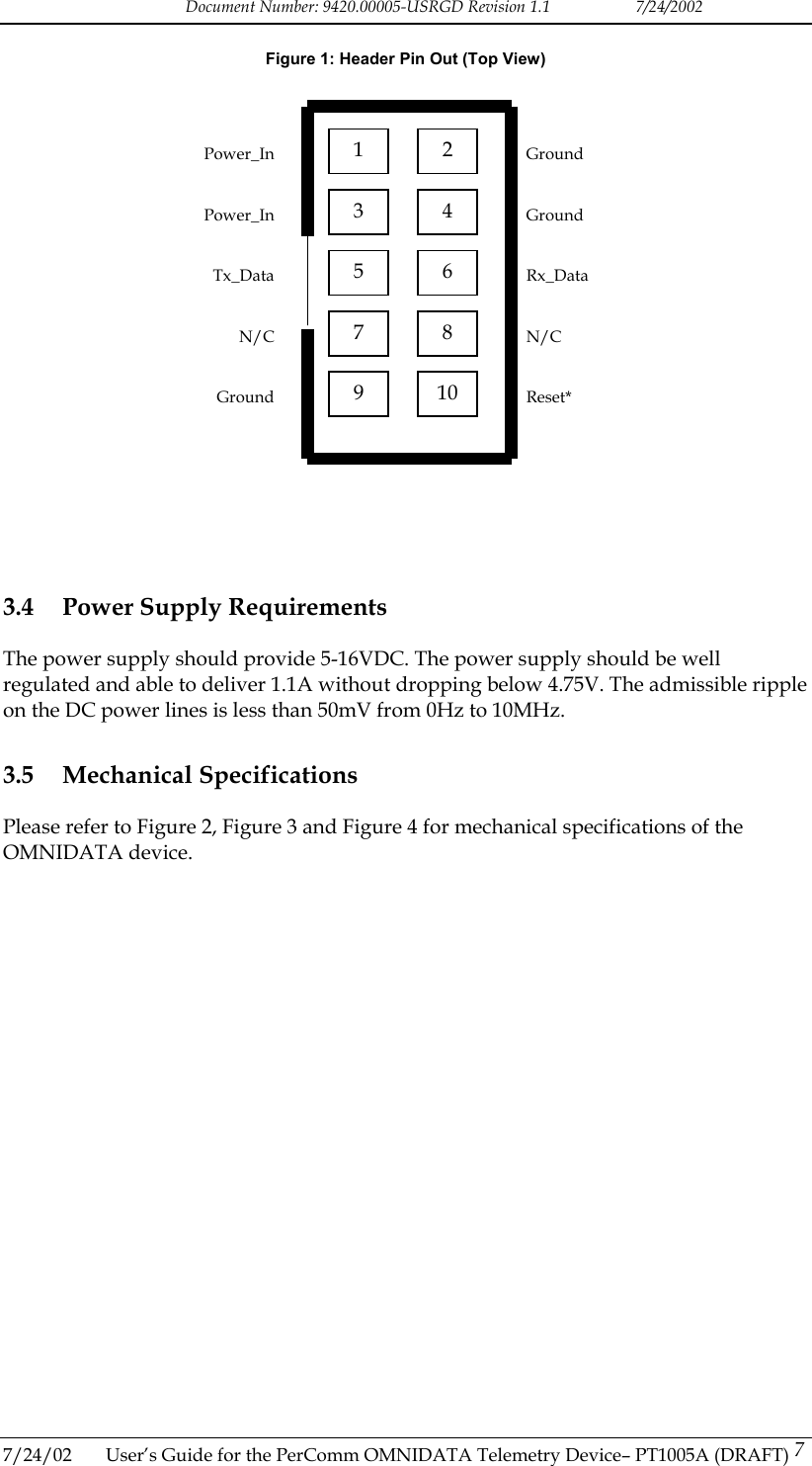
![Document Number: 9420.00005-USRGD Revision 1.1 7/24/2002 5. Turn on the power supply. Follow the instructions in Section 4.3. 4.3 Power-On Procedure After power has been applied, follow the instructions listed here to verify operation of the OMNIDATA device. Please refer to the appropriate host interface protocol document (HCI [2] or CLP [3]) to determine how to execute these instructions. 6. Query the OMNIDATA device with the host. Verify that the host is able to communicate with the OMNIDATA device. 7. Periodically poll the OMNIDATA device until the device has registered on the ReFLEX network for full two-way service. 8. Use the host and OMNIDATA device to send a message to the PIN or email address associated with the OMNIDATA device being used. Verify that the message is successfully accepted by the ReFLEX network. Verify that the message is successfully received by the OMNIDATA device. 4.4 External Antenna Guidelines The OMNIDATA transmitter was designed for a 50 ohm external antenna. The same antenna is used for transmit and receive and so, the antenna has to work from 901MHz to 941MHz. It is possible to connect the external antenna directly to the device or through a coax cable. The external antenna should be mounted close enough to the OMNIDATA unit to limit the length of the cable and the losses in it. The external antenna assembly must have a standard male SMA connector. If the load presented by the external antenna assembly at the SMA port is not 50 ohms, the output power of the transmitter and the DC current consumption during transmit time may vary from the nominal values. The VSWR of the external antenna assembly in the transmit band 901 to 902 MHz should be less than 1.7. If the VSWR is greater than 1.7, the transmitter might be permanently damaged. The solution is to have the antenna re-matched or to impose restrictions on the length of the cable between the external antenna and the unit. Please contact PerComm for further details. The external antenna is not supplied by PerComm. For FCC certification PerComm used a Larsen antenna (model: SPWH20918) with a 4”x4” ground plane. The antenna was connected by a 3 feet coax (RG45/U) to the OMNIDATA device. This installation meets the FCC’s limits for effective radiated power (e.r.p.). 7/24/02 User’s Guide for the PerComm OMNIDATA Telemetry Device– PT1005A (DRAFT) 11](https://usermanual.wiki/PerComm/1005.Usr-Manual/User-Guide-267584-Page-14.png)