Perfect Toys Co SPORT-F1 sport-F1 (Model no.: P-30133) User Manual Manual
Perfect Toys International Co Ltd sport-F1 (Model no.: P-30133) Manual
Manual
1(243lx3503xl6Mjp€g)
Safety Direction
Thb mod6ll! nota
loyl E.roroperstion wlllcauso
dang€rl In
order
to
oporate 3aiety
pt.ase
.€ad
followingsl
Notice Before Installation
l Make
sureyo! have connecled
the battefy
polarly
belween transmitr€rand fece ve.corecltyor
youwl
damagelhenode.
2.Yousho!ldLsecorespondinOp.odlces(suchaslransminer,receiver.ESCandotheroplional
parls)prodrcedbyPERFECTcompanyWedonll.keanydulyonthetosinqbyusngorher
/oTo.r ' 5
piocL.rs
lnstallation
Pf ecaution
1 The
p.od!clisdes
gned
lor re mote
conlrot mod e onty.N€v€ruseiorotherserrings.
2 MakesurelouselrsnsmltercrystalandreceivercryslatontyproducedbypERFECTcompany.
Other
cryslalmay cause los ng
conl.olityou chanse 116quency.
3 f
you
are lsins Nicad
batlefies, charge berofe
us ng. Orherwis6 il wititose
conlrotlorshort n9
4 Makesureyouhaveconnectedallinstatalionco(ecry.ThetoosenconneclionwiIcausethe
frodelloslng
conlrol.
5.lnstallhereceiverwirhthickdoubtegue.tnrensiveoscilstionandstrikewilcauserhefrodsJ
6.Nevercurtheanlennaortrussilwirholherwire
olherwise
lne sense olthe fec€iver w rt red
uce
and |nesetuowill
getdamaoed.
7 Make
sufe lo use lhe
shockprootwash6rwhire
instatting the servo. The
oscltalion wi
damage
rhe servoand
ca0se llos ngconkol.
Operalion
Precaution
1 Ens!relhefreq!encybefoi€
lurningon
powerswjrch.
Some modets ustng rhesan.frequency
wi I
resultin runn n9
outcontrol
2 Avoidusingitatlh!ndefslormday
The ightningmaystrtkerheti
ingslhro!gh$eantenna.
3.Avo'dusinoitinswampplace
Senousdampwttcausethemode
osngconlrot.
4. Noveruselhemode
n folowing
suroundings:
Near
otherleleconlro veh
cte c.cuit
{i. 1 0 meters).
Near the crowd
orr!f onth€pavenent
Near lhe w re
and other communicalion
inslattat on.
O.ce the mode osescontro iw causedanger
5. Extend the w re
to the longest
prace
orlhe signalwi treduce
aod cause the mode osing conlrol.
6 Make
sure
you
hav€
stoppedengin6operaltonand
cu he motofwnes
ofibetorerestand modily
lheiunclionsetting.
7. Refrember
to t!rn on the transm
lter and rece ver
orde.ty wh te slarling.And oppos
lety
white
turnoff . Olherwlse
you
may cause
the model osrng donlro
L Lel other
peopl€
know
yourlreqLency
while
oper6t on.
9 Neverlouchtheengine,motorandESC
'lireyareheatoryouwi burnyou.sef.
10.Ihe
lransmiller sends
high frequency s
9na
. Never to!ch the anlenna
white usinq.
o
Notice
Afler
Operalion
1. Make
sure ro cul olllhe Nicad
baltefies
ait€rrsing the etechic mod€tvehicle.
otherwise
lh6
power
swrlch ns
on wlll causeiireand
lhe modetwitt tos6contfol.
2 Pll lhe kansmiiler,
battery and the modetout
ofch tdfen,s rea.htOthetu
se the
chemicat material
3 Take
the baltefi6s
out ifyou don l wanl
lo use lhem,of a tong time.
4 Neverstorathelransmitter
n fo]owin9
p
aces:
lD Iempreture over40C and beiow 1O'Cj
-4, Th€
sun shlnes d rect
y
Storinglhemode
inthesu(oundingabovewiltcauseincorecrtyoperali.gandcauserh€model
Chafging
Precaution
l Neverletthebatlefyshortcncuilorputirintoft.eoryouwi
causeflrcanddanger.
2 Neverletth6
balte.iesshake
Ilerce
y.
Olheruiserhe baieriesw|tbe
dahaged
and cause shon
3. Neverletthe
blter es
getwetorchargewhitethe
baller es arewel Otherwise Iw I makelhem
loo heatandcausedamage
4 Nlake
sure lo use lhe PERFECT
charqer
corectty and use
propercha.gjng
cu(enl. Avoid
ove.
charging.Olherwiseyoumaydamaqelhedaneriesa.dcauserr.eandserousaccident.
I
L

Catalogue
1. Whole Model Introduction Diagram
2. Transmitter Specification
3. System Configure and Connection
4. Installation
and Operation
I nstallation of transmitter
A. Installthe battery
B. Installthe
antenna
C. Install the receiver and servo
D. Change the direction adjusting wheel
position
5. Technical Data
6.
Fittings Packing
7. Production
Service and Guarantee
-t
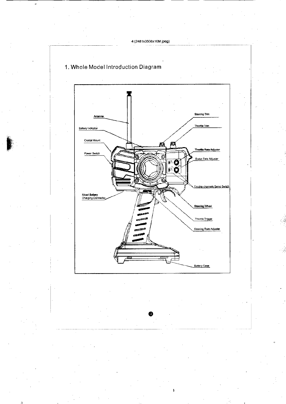
1. Whole
Model Introduction Diagram
o
I
,g
i
i
i.
i
Welcome
to use SMARTECH
ser;es. With hiilh
quality
and advanced
technology,
30133
product
wiil
make
your
modet
oplimal
performance.
2.
Charactef and Function
Fl'/dorble-channe
s
R/C
systen
Double channels servo non t&rea
I switch
Three
baltery
lnd
cator liOhrs
Steering ral6adjusler
Nicad batlery
charged inte{ac6
sleering
adlusllnq whee
posilioncanbelransposed
nlotefthaodandfighthandexped€nlty
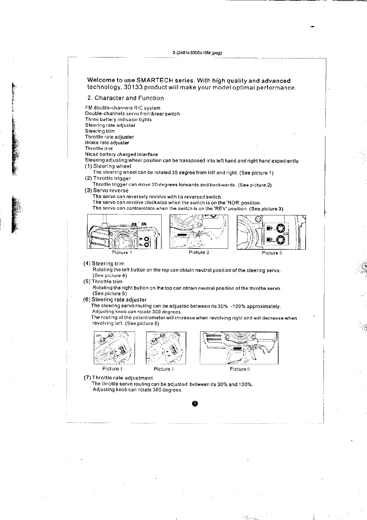
Thesteeringwheelcanberoraled35degreeliomteft
andrghl (Seepicturel)
(2)Throitle
trigger
Throtllelrlggercan
move 20degreesfotuafds
and backwards (See
p
ctore2)
The servocan reversely
revotve with its
reversed switch.
Jheservocanrevolveclockwisewhentheswitchisonlhe
NOR
posirion.
Theservocanconlrarotatewhentheswilchisonthe'REV
posilion
(Seepiclure3) I
i4)
Sleer ng tr m
Rolal ng the left
bullon o. the top c.n
oblain neuiratposilion ofth€ sleef
ng servo.
(5)Throllletrim
Rolaling
the right b!tton
on lhe top can obtain naulratpositio.
ofihe thro te s€rvo.
(6)
Steerins
rate adjusler
Thesl€erlngservoroulingcanbeadiustedbetw6enrts30%,100%approiimatety.
Adlusting knob
can
rotate
300 d€grees
The rour
ng of the
potent
omelerwi lincreds€ when
revotvtng riqhr and wi
d€.rease
when
reloivino eft (See
picture
6)
'€
:.i
(7)
Throttle
rale adjustment
The throrrre
servo rollingcan
be adiusted belw€€n
its 3Oaha^dlAjon.
Adjusrin9
knob
can forare 300 degrees
e
When revolving cl;ckwis6 the rouu ng ofthe knob willlncfease
. Thero!tln9oll dec6asewhiecontrafolallng.(Seepicl!re7)
(8)
Brake rale adlustmenl
The
throlt e b.akeservo s fouring can be adj!sted between ls 30% and 100%.
Adjusling knob can rolate 300 degrees
Whenrevovrngclockwsethefoutngoltheknobwillincrease.
The
rout ng willdecease wh le contrarolat ng.
(See
picture
8)
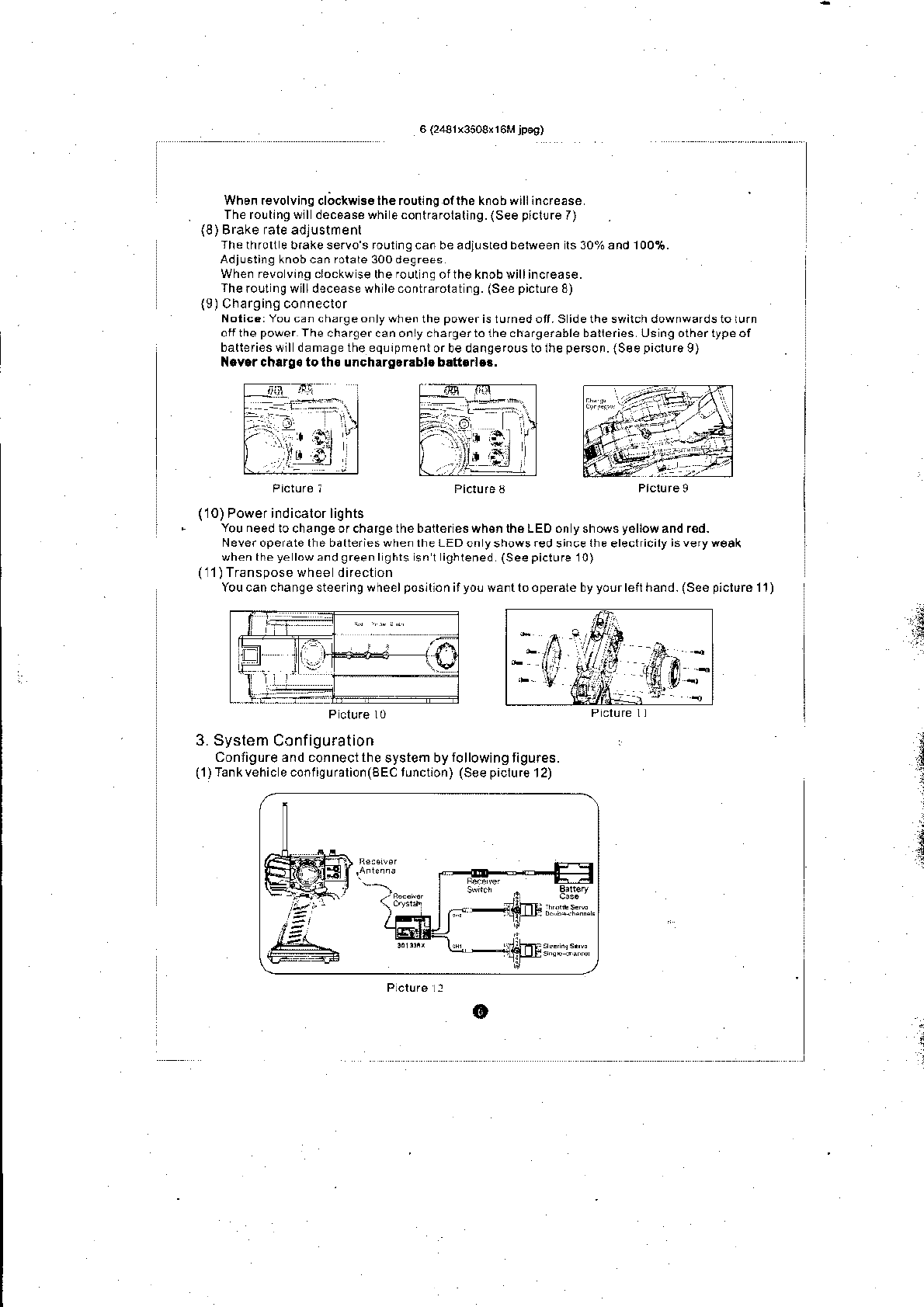
(9)Charging
conneclor
Notic.:YoLcanchErgeonlywhenthepowerisrufnedott.Sidetheswirchdownwafdstolurn
ofi thepower
Thechargercanonlychargertolhechargerableballeries
Us n9othertypeof
batlefieswll damasetheeq!rpmentorbedangefolstolheperson.{Seepiclu.o9)
N.v.rchrrg. to th. uncharg.r.b!. b.tt..l.!.
Picture i Picture3 Piclureg
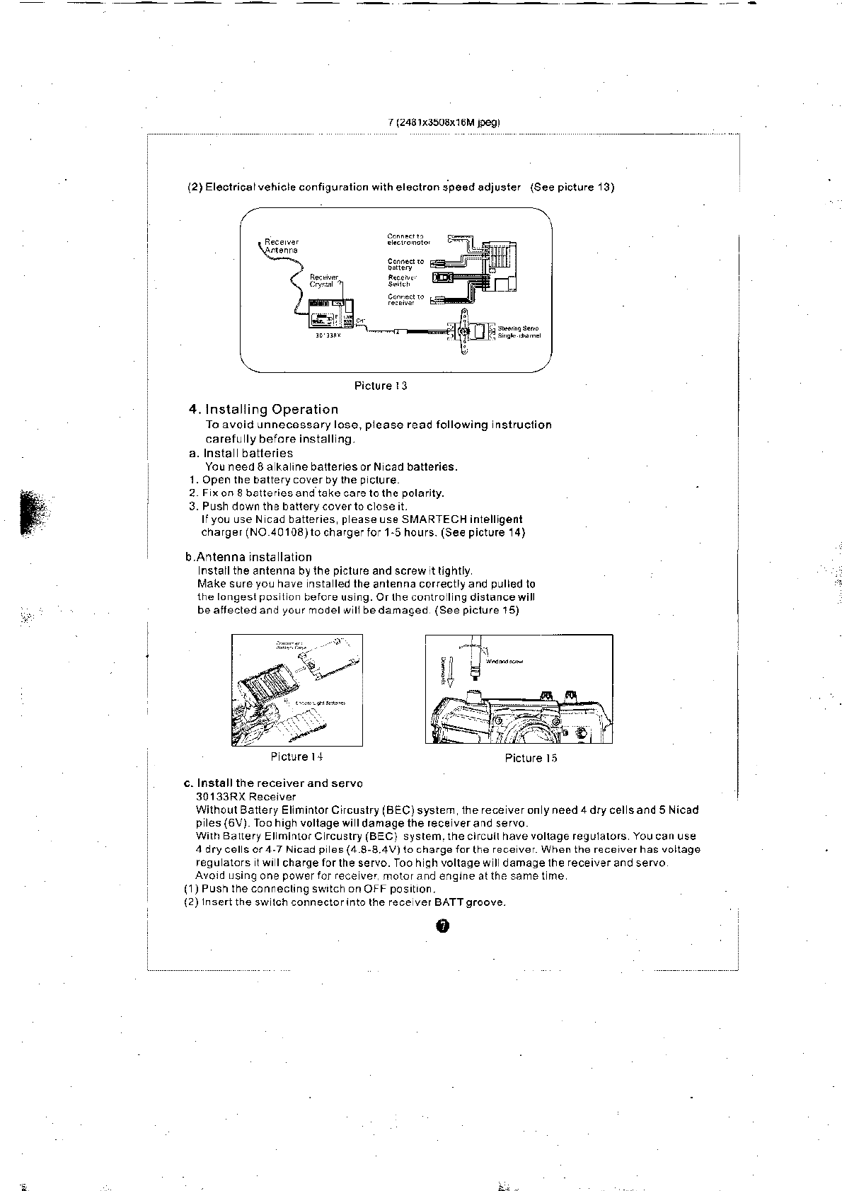
(10)
Power indicalor lights
You need
lochangeofcharge the batleries wh€n the L EO on
y
shows
y6llow
and red-
Never operate the batteries when lhe LED
on
y
shows
red
since
lhe
electricily
is veryw€ak
whentheye lowandgreenl9hls
snr ighlened (See
piclure
l0)
(11)
TransDose whee difect on
You can change steer ng wheelposllion ifyo! wantlo operale by
your
left hand.
isee
piclure
11)
P cl!.e l0
3. System
Configuration
Conligure 3nd conneci the
system by
following
tigu.ss.
(1)Tankvehic
econriquralioi(sEc tuncuon)
(See piclu,s
12)
o
j
,i
:
(2)Fl€clflca
lehrcecorfrgu alionwrheleclror
sp€edadjusre
(Seep(tJre'3)
Picl!re
r3
4. lnstalling Operation
To avoid unnecessary lose,
please
read following nslruclion
carefu ly
beio.e
insiall ng.
You need 8a ka ine batteriesorN cad batteries.
1. Open the baltery coverbylh€
p
clure
2 FxonSballeriesandtakecafelolhepolarily.
3. Push down the batlery.overto ctose it.
lfyoL use N cad batteries
p
ease Lse SMARTECH inlelligent
charger (NO 40103) lo
charger ior l-5 hours.
(See
picture
14)
b.Anlenna insta lalion
nsiall the anlenna by ihe
piclure
and screw lt ll9hlly
Makesu.eyo!have nstaledlheantennacorectlyandpullodlo
the longesl
pos
lon berore us ng.Orlhecontrollngdislancewill
beaitecledandyo!rmodelwllbedanaged
(Seepiclurel5)
P clure 14 Picture li
c. Insl€ll the receiver and seruo
Wilh.!lBalleryEllnintorCircuslry(BEC)system the rece veron
y
.eed 4 dfy cel s and 5 Nicad
p
les(6V) Too high vollage wi I
da
mage
the
rece verand
servo
wilh Baltery
Elminto.C rc!slry
iBEC)
system.thecircuilhavevollagereguialors Youcanuse
4drycelsor4-TNicadpies(48-8.4V)lochargelorthereceverWhentherecerverhasvoltage
re9uatorslwrlchafgerorlhese.vo.-foohghvollagewlldamagelhereceivera.dservo
Avord!sinltonepowerforre.eve.
rotorandensineallhesametne
(1)
Push lhe connocting swrich on
OFF
positron.
(2)
lnsertthe
sw lch connectorinto rhe rece ver BATTgroove.
o
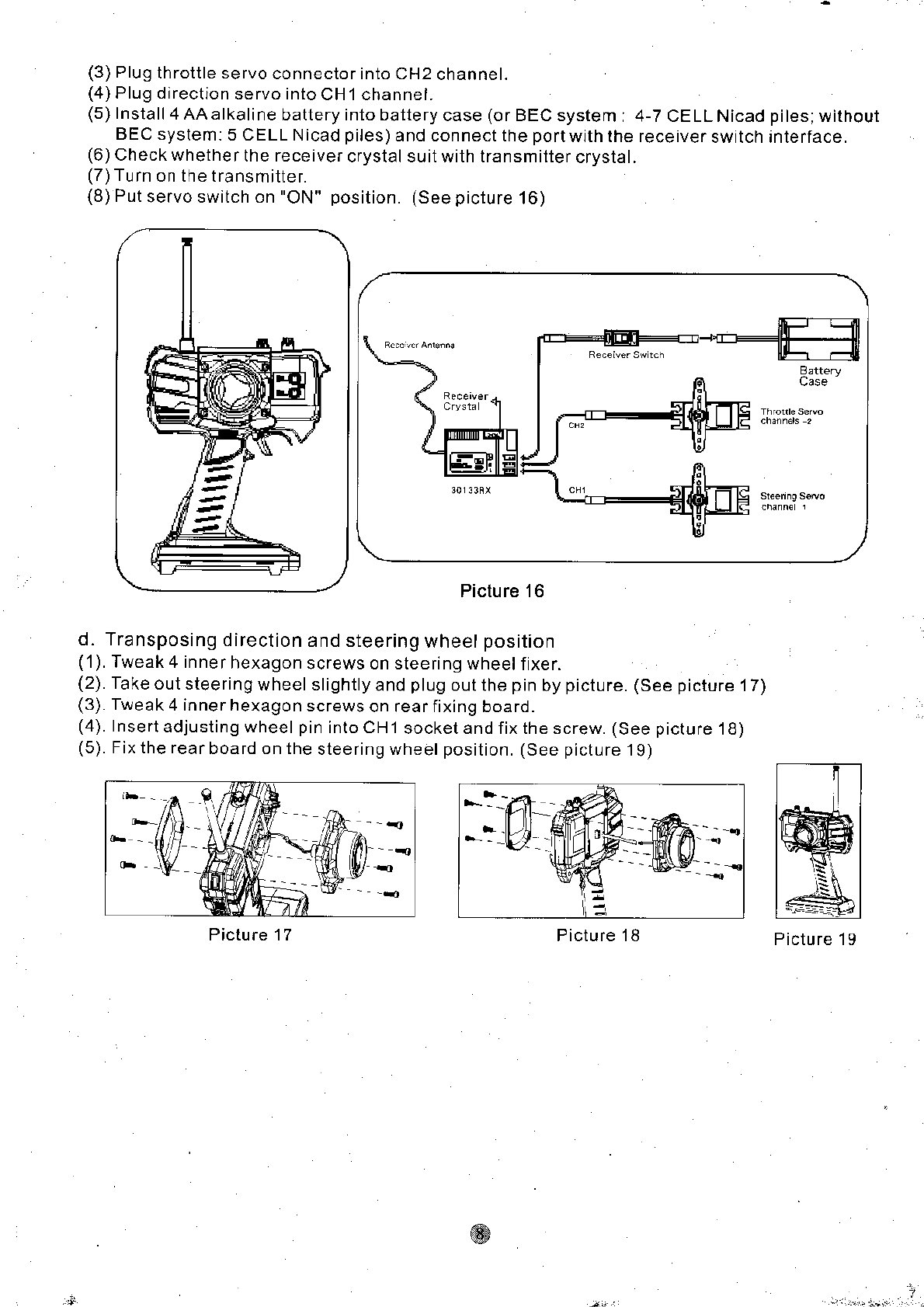
(3)
Plug
throttle servo
connector into CH2
channel.
(4)
Plug direction
servo into
CH1 channel.
(5)
Install
4AAalkalinebatteryintobatterycase(orBECsystem:4-TCELLNicad
BEC system:
5 CELL N icad
piles)
and connect the
port
with the receiver
switch
(6)
Check whether
the receiver
crystal suit with transmitter
crystal.
(7)Turn
on the transmittef.
(8)
Put
servo switch on
"ON"
position. (See picture
16)
piles;without
interface.
Picture 16
d. Transposing
direction
and steering
wheel
position
('1).
Tweak 4 inne
r hexagon
screws on steefing wheel
fixer.
(2).
Take
out steering
wheel slightly
and
plug
out the
pin
by
picture. (See picture
17)
(3).
Tweak
4 inner hexagon
screws
on rear fixing board.
(4).
Insert
adjusting wheel
pin
into CH1
socket and fix the screw.
(See picture
'18)
(5).
Fix the rear
boafd on the
steering wheel
position. (See picture
19)
Picture 17 Picture 19
l7L _
| -!t HI tf tl
Picture
'18
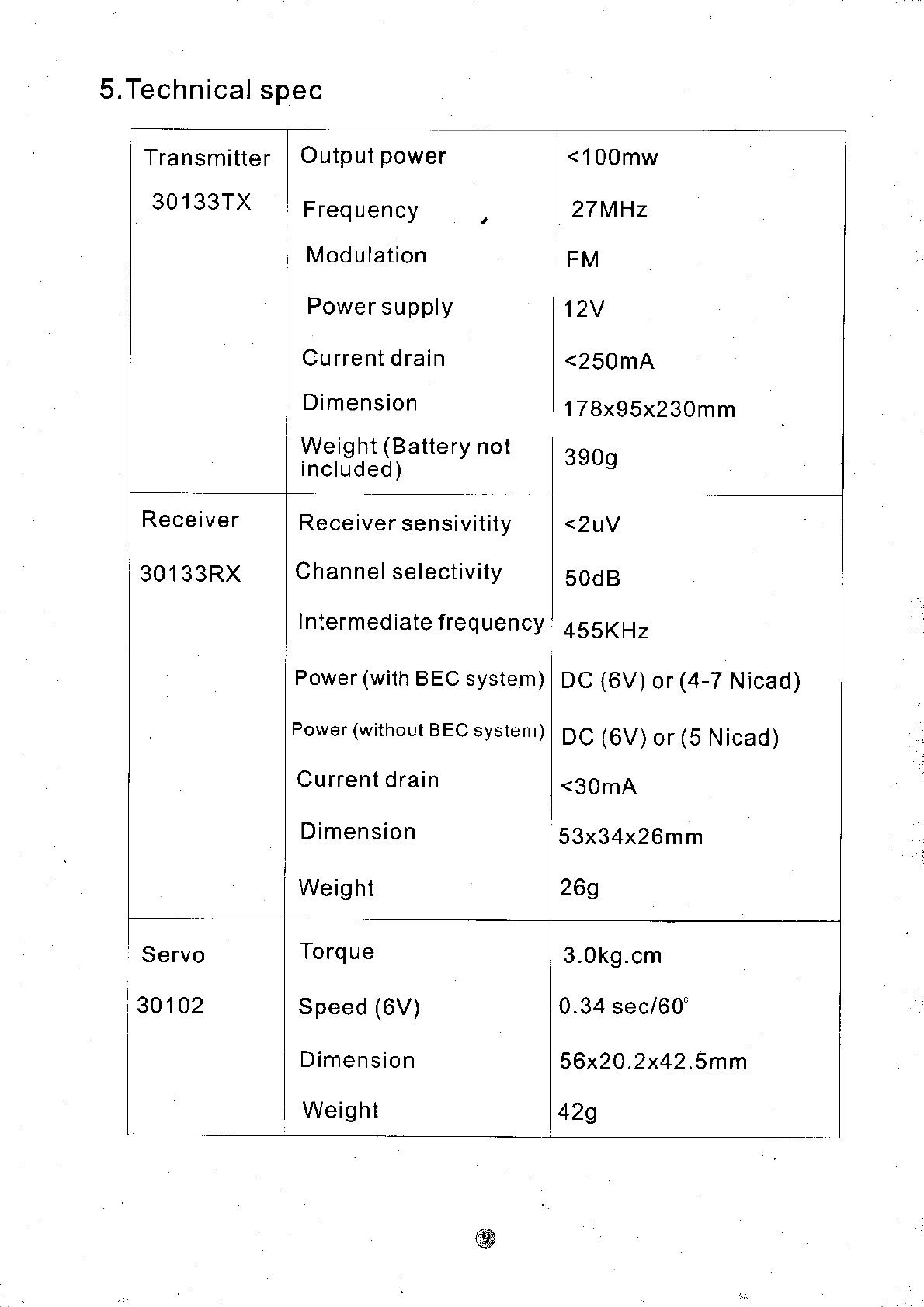
5.Technical
spec
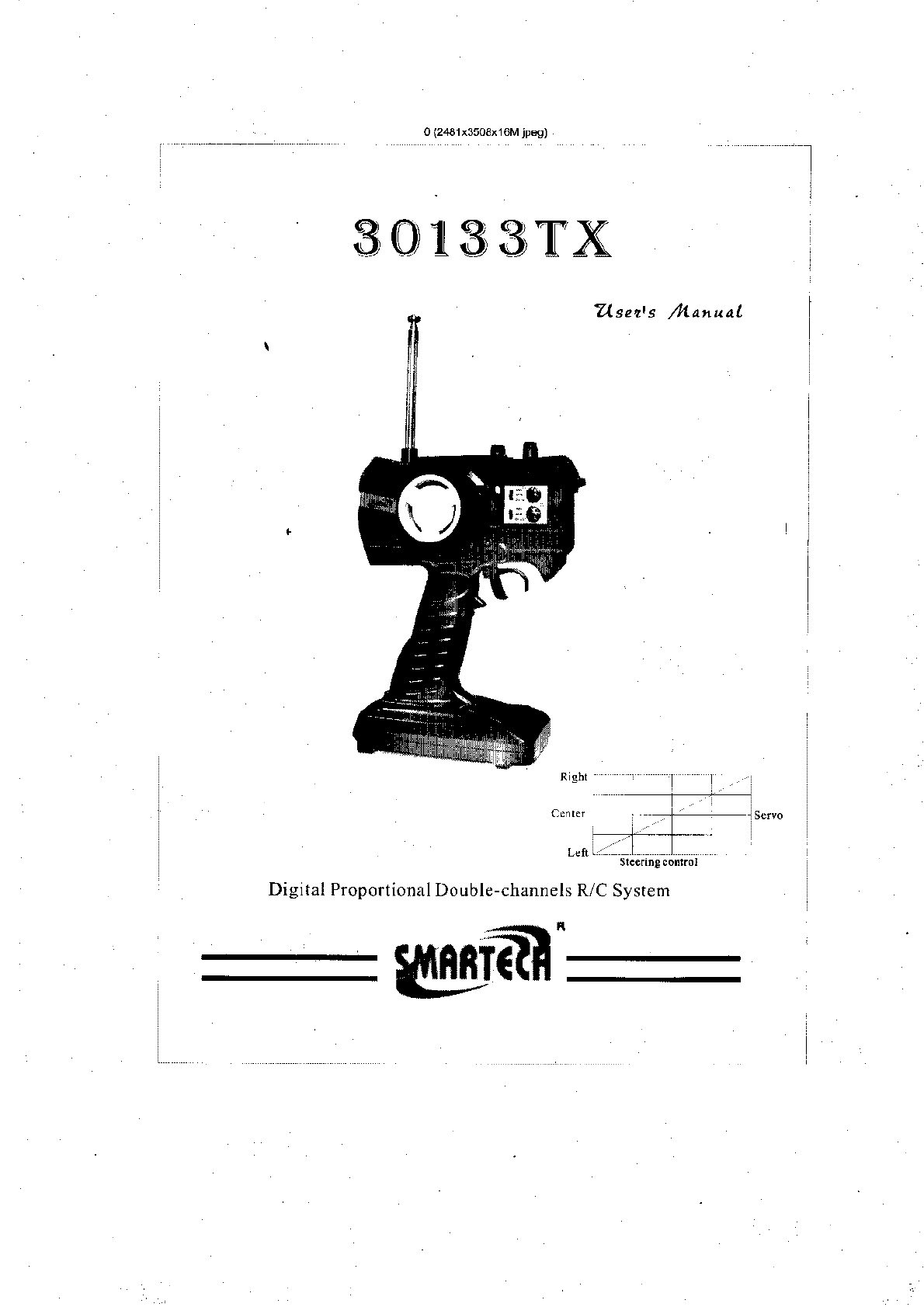
Transmitter
30133TX
Receiver
301 33RX
Servo
30102
Output
power
Frequency
M od u lation
Power
su
pply
Cu rrent drain
Dimension
Weight
(Battery
included) noI
Receiver
sensivitity
Channel selectivity
Intermed
iate frequency
Power
(with
BEC system)
Power (without
BEC
system
)
Current
drain
D imen sion
We
ig ht
Speed
(6V)
Dimension
Weig
ht
<100mw
27MHz
FM
12V
<250
mA
178x95x230mm
3909
<2uY
50d B
45SKHz
Dc
(6V)
or
(4-7
Nicad)
DC
(6V)
or
(5
Nicad)
<30
mA
53x34x26mm
269
3.0kg.cm
0.34 sec/60"
56x2O.2x42.Smm
42g
r0 (2431i3503x16M jp€g)
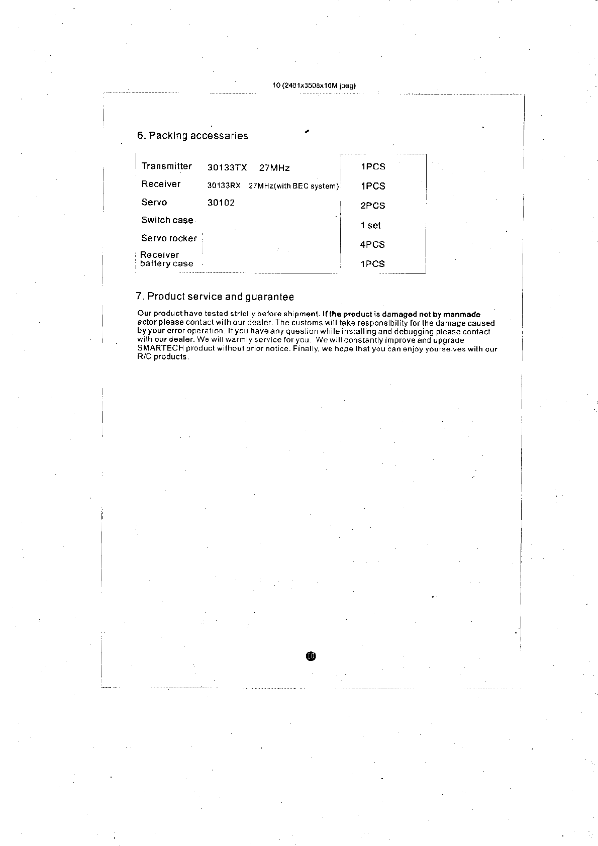
6. Packing
accessaries
Tiansmilter 30133TX
Receiver 3o133Rx
Servo 30102
Servo rockef
27[rF]z(with BEC ayslem)
27 MHz lPCS
lPCS
2PCS
4PCS
lPCS
7. Producl
service and
guarantee
Our p.od!cthav6 tesled
strict
y beiore sh pms.t.lfthe prodlct ls da naosd nor by nanmado
actorpleasecontaclwilho!rdealer'ahecustomswitttakeresponslbiiitylorlhedamaqeca!sed
by
your
eror ope rat on llyouhaveanyquestronwh
le insta Ing
and debugging
ptease
contact
wlhoudealer.Wewiirwdmyservlceforyou wewrt const6ntytmproveandLpgrade
SMARTECHproductwlhourprornotce.Finaly.wehopelhalyouaanenjoyyoursetveswilhour
o
l
Zleetts /l4anual
Digital Proportional
Double-channels R/C
System
30n33TX
Sllrn'