PhaseSpace IMPULSE MOTION CAPTURE SYSTEM RF TRANS User Manual USERS MANUAL
PhaseSpace, Inc. MOTION CAPTURE SYSTEM RF TRANS USERS MANUAL
USERS MANUAL

PhaseSpace Impulse: LED System
COPYRIGHT
This manual is copyright 2006, PhaseSpace, Inc., All Rights Reserved. This document may
not, in whole or in part, be copied, photocopied, reproduced, translated, or reduced to electronic
medium or machine-readable form without prior consent, in writing, from PhaseSpace, Inc.
The distribution and sale of this product are intended for the use of the original purchaser only.
Duplicating, selling, or otherwise distributing this product is a violation of the law.
DISCLAIMER
PHASESPACE INC. MAKES NO WARRANTIES, EITHER EXPRESSED OR IMPLIED, WITH RESPECT TO THE
SYSTEM DESCRIBED HEREIN, ITS QUALITY, PERFORMANCE, MERCHANTABILITY OR FITNESS FOR ANY
PARTICULAR PURPOSE. THIS SYSTEM IS SOLD “AS IS”. THE ENTIRE RISK AS TO ITS PERFORMANCE IS WITH
THE BUYER. SHOULD THE SYSTEM PROVE DEFECTIVE FOLLOWING ITS PURCHASE, THE BUYER (AND NOT
PHASESPACE, INC. THEIR DISTRIBUTORS OR THEIR RETAILERS) ASSUMES THE ENTIRE COST OF ALL
NECESSARY DAMAGES. IN NO EVENT WILL PHASESPACE, INC. BE LIABLE FOR DIRECT, INDIRECT,
INCIDENTAL OR CONSEQUENTIAL DAMAGES RESULTING FROM ANY DEFECT IN THE SYSTEM EVEN IF IT HAS
BEEN ADVISED OF THE POSSIBILITY OF SUCH DAMAGES. SOME LAWS DO NOT ALLOW THE EXCLUSION OR
LIMITATION OF IMPLIED WARRANTIES OR LIABILITIES FOR INCIDENTAL OR CONSEQUENTIAL DAMAGES, SO
THE ABOVE LIMITATION OR EXCLUSION MAY NOT APPLY.
PhaseSpace and the PhaseSpace logo are registered trademarks, and all PhaseSpace product
names are trademarks of PhaseSpace, Inc.

FCC Compliance Statements
WARNING: Changes or modifications not expressly approved by the party
responsible for compliance could void the user’s authority to operate the
equipment.
Note: The PhaseSpace Impulse system is delivered with shielded Ethernet
cables. Shielded Ethernet cables are required to comply with emissions
limits. It is the responsibility of the user to use the supplied cables.
Note: This equipment has been tested and found to comply within the
limits for a Class A digital device, pursuant to Part 15 of the FCC Rules.
These limits are designed to provide reasonable protection against harmful
interference when the equipment is operated in a commercial environment.
This equipment generates, uses, and can radiate radio frequency energy
and, if not installed and used in accordance with the instruction manual,
may cause harmful interference to radio communications. Operation of this
equipment in a residential area is likely to cause harmful interference in
which case the user will be required to correct the interference at their own
expense.
Industry Canada Compliance Statement
This Class A digital apparatus complies with Canadian ICES-003.
Cet appareil numérique de la classe A est conforme à la norme NMB-003 du
Canada.
CE Compliance Statement
WARNING: This is a class A product. In a domestic environment this
product may cause radio interference in which case the user may be
required to take adequate measures.
WARNING: DO NOT connect or disconnect devices to the HUB while the
server computer is on. The LED Base Station is considered a device and
should only be connected or disconnected while the server computer is off.
WARNING: Only use standard shielded Ethernet cables with the
PhaseSpace system. DO NOT use crossover cables.
WARNING: The six-pin port on the LED Base Station is only to be used to
connect to LED Driver Units. DO NOT use this port to connect to any other
device.
2
Document Purpose
This purpose of this document is to describe the LED component of the
PhaseSpace Impulse system. The items covered are:
• LED Base Station description
• LED Driver Unit description
• LED String description
• LED Module description
• LED String creation
• LED system setup procedure
3

Table of Contents
1: LED SYSTEM DESCRIPTION .........................................................................5
1.1 LED BASE STATION.......................................................................................5
1.2 LED DRIVER UNIT .........................................................................................6
1.3 LED STRINGS ...............................................................................................9
1.4 LED MODULES............................................................................................10
2: LED STRING CREATION ..............................................................................11
2.1 ATTACHING CONNECTORS TO THE LED CABLE ..............................................11
3: LED SYSTEM SETUP....................................................................................14
3.1 LED HARDWARE SETUP...............................................................................14
3.2 LED STRING FILE SETUP .............................................................................15
TECHNICAL SUPPORT.....................................................................................17
4
1: LED System Description
The PhaseSpace LED (Light Emitting Diode) system can be classified as
the data-generating side of the PhaseSpace Impulse system. The individual
components of the system are described in this section.
1.1 LED Base Station
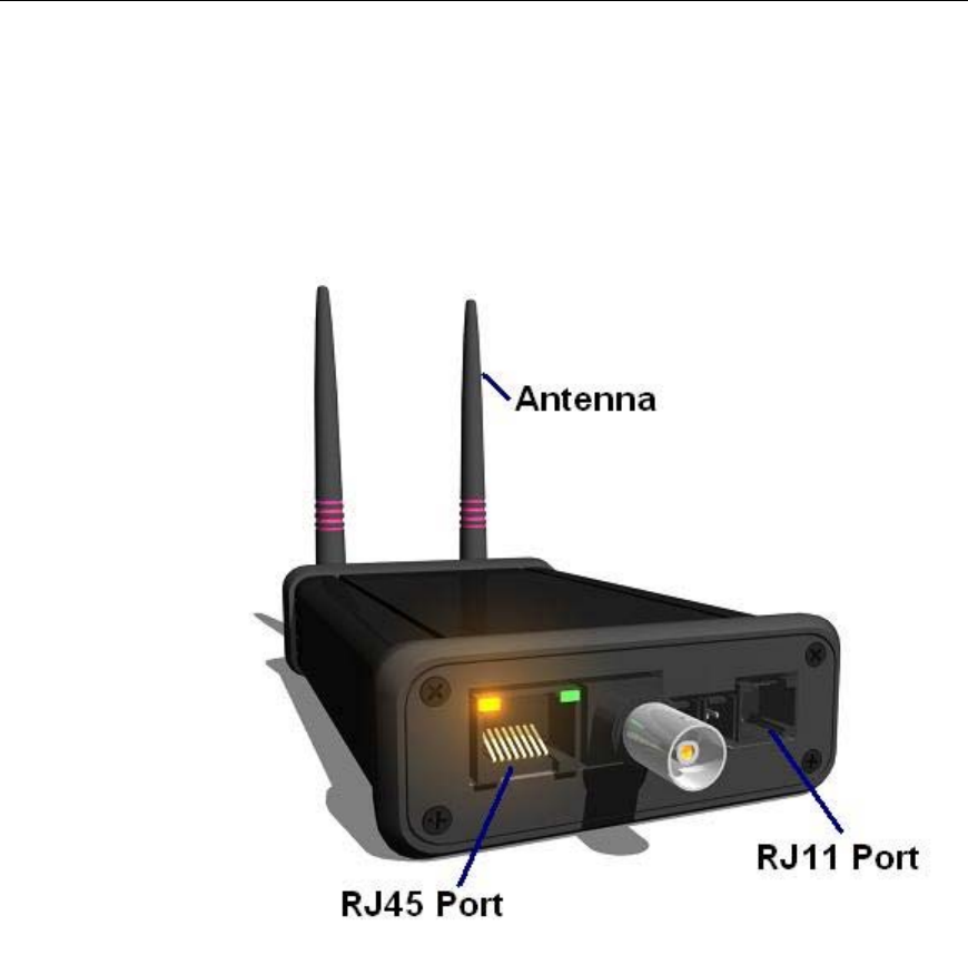
Figure 1.1.1: LED Base Station
The LED Base Station functions as the primary link between the
PhaseSpace HUB and the LED system. The base station is connected to
the HUB by connecting one end of an ethernet cable to a port on the HUB
and connecting the other end of the cable into the ethernet (RJ45) port on
the base station.
The LED Base Station has these functions:
5
• Transmission of timing signal to the LED Driver Unit(s)
• LED programming
The base station also has the capability to drive LED strings
independently.
The interfaces on the LED Base Station are:
• One 6-pin (RJ11) port
• One 8-pin ethernet (RJ45) port
• LED string ports
• External RF antennae
The LED Base Station transmits a timing signal via the RF antennae (or
directly through a 6-pin connection) to the LED Driver Unit. This signal is
sent once per frame.
1.2 LED Driver Unit
The LED Driver Unit is the driver of the LED modules. The unit consists of
a battery pack as well as an RF receiver, which receives a timing signal
from the LED Base Station. The interfaces on the upper edge of the driver
unit are (refer to Figure 1.2.2):
• A power/reset button
• A 6-pin (RJ11) port
• A 14-pin LED string port
In tetherless mode the LED driver unit is turned on by quickly depressing
the power/reset button. In tethered mode, the unit automatically turns on
when connected to the base station. To turn off the unit, the button should
be held down for at least a second.
IMPORTANT NOTE: If the power button is held down too long when
turning the unit on, the unit will not power up and it will be necessary
to wait a few seconds before the unit can be turned on.
6
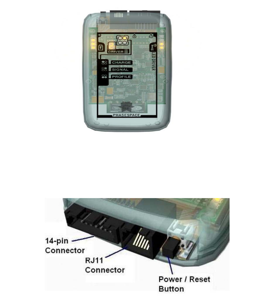
Figure 1.2.1: LED Driver Unit
The battery pack is charged by connecting the driver unit to the LED driver
charger. From a completely discharged state the battery pack should take
two to three hours to fully charge.
Figure 1.2.2: LED Driver Unit connector view
A total of six LED strings can be connected to the 14-pin connector using
a six-wire breakout adaptor or a six-port breakout box.
The face of the LED driver unit has a set of function indicator lights (Figure
1.2.3).
7
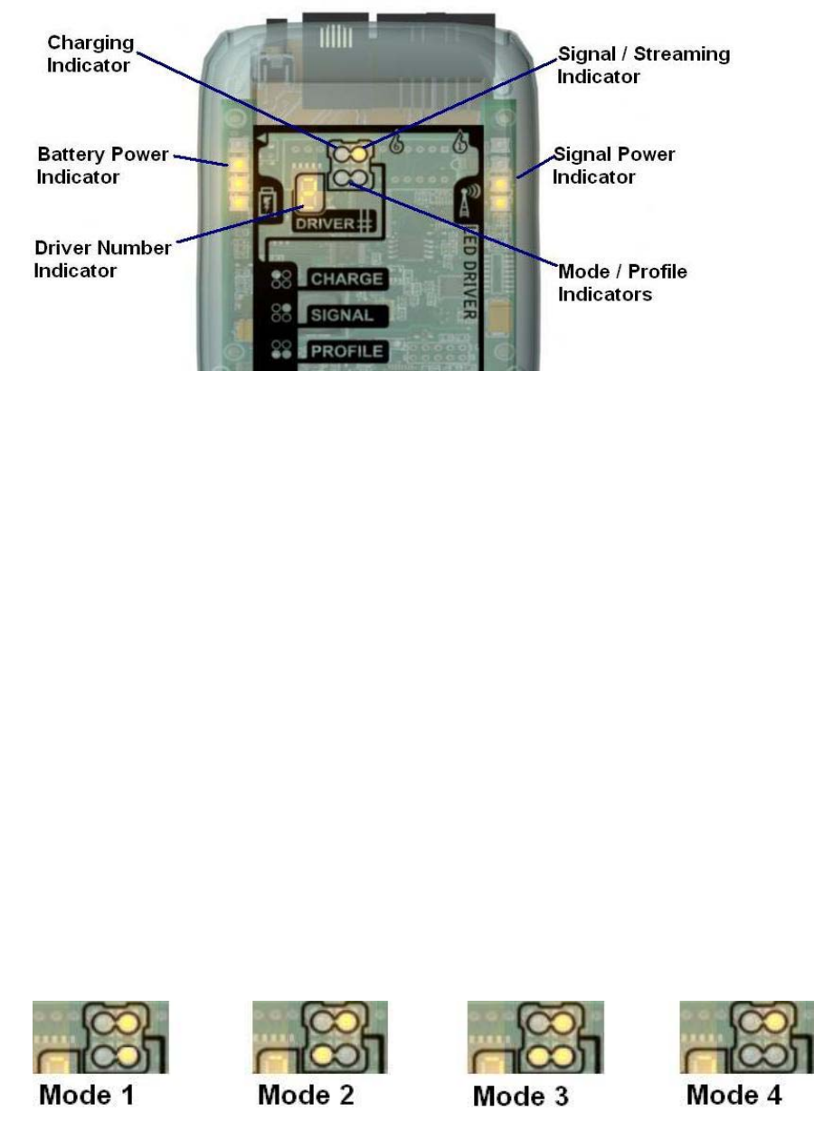
Figure 1.2.3: LED Driver Unit indicators
The indicators give the following information:
• Battery Power - The leftmost column of four lights indicates battery
power
• Signal Power - The rightmost column of four lights indicates signal
power (tetherless mode)
• Driver Number – The numeric indicator shows the driver number
assigned to the unit. During calibration this indicator will display the
letter “C”.
• Mode / Profile – The bottom two lights of the group of four lights
near the center of the face of the unit show the mode / profile that
the system is using (refer to Figure 1.2.4).
• Signal / Streaming – The upper right light of the group of four lights
is on when the system is streaming data and a signal is being sent
to the unit.
• Charging – The upper left light of the group of four lights is on when
the unit is charging.
Figure 1.2.4: Mode indicator states
8
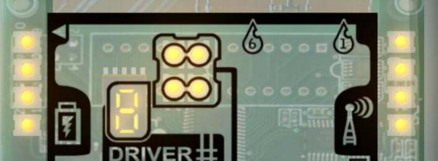
The LED driver unit is encoded by connecting it to the LED base station.
Within five seconds of connecting to the base station all the driver unit
indicator lights will turn on (refer to Figure 1.2.5). This is an indication that
the unit is ready to be encoded. For more information about encoding refer
to the PhaseSpace Impulse: Configuration Manager document.
Figure 1.2.5: LED Driver Unit is ready to be encoded
1.3 LED Strings
An LED String consists of:
• The LED cable
• The LED cable connectors
The LED cable consists of two wires, one of which is colored. The
connector has two sockets, one for each wire of the LED cable.
A total of six LED strings can be attached to a single 14-pin connector,
which connects to the 14-pin LED string port on the LED Driver Unit. Each
LED string is capable of having up to 12 LED modules attached to it using
the proper LED connectors. Each LED module on a particular LED string
must have a unique LED designation, i.e. two LEDs with the same
designation should not be connected to the same string.
9
1.4 LED Modules
The LED modules contain the actual light sources that are tracked by the
PhaseSpace cameras. Along with the light source is a microprocessor that
controls the modulation of the LED’s pulse duration and amplitude.
Each LED has one of 12 LED designations (labeled A through L). This
designation along with the identifier of the LED driver gives each LED a
unique identifier.
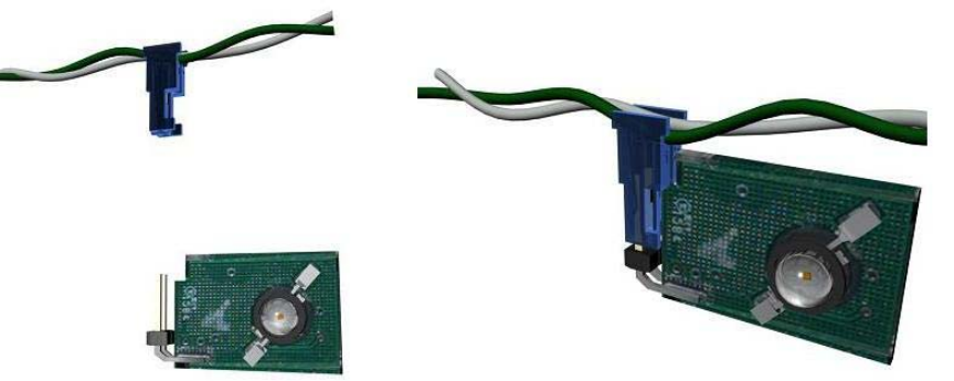
Connecting an LED module to an LED string is illustrated in Figure 1.4.1.
The prongs of the LED module should be pushed completely into the
connector on the string. There is only one way to push the module into the
connector, so care should be taken not to force the connection.
Figure 1.4.1: Connecting LED Module to LED String
IMPORTANT NOTE: A maximum of 12 LED modules can be
connected to a single LED string and there cannot be any repeat of
LED designation on a single string.
10
2: LED String Creation
In general, the LED Strings are delivered “unpopulated”, meaning that
connectors are not attached to the LED cable. This is due to the fact that
the placement of connectors on the cable is dependent on the particular
motion capture application. Leaving the LED strings unpopulated allows the
user to customize the position of the connectors on the LED cables.
2.1 Attaching Connectors to the LED Cable
Populating the strings requires attaching connectors to the LED cable
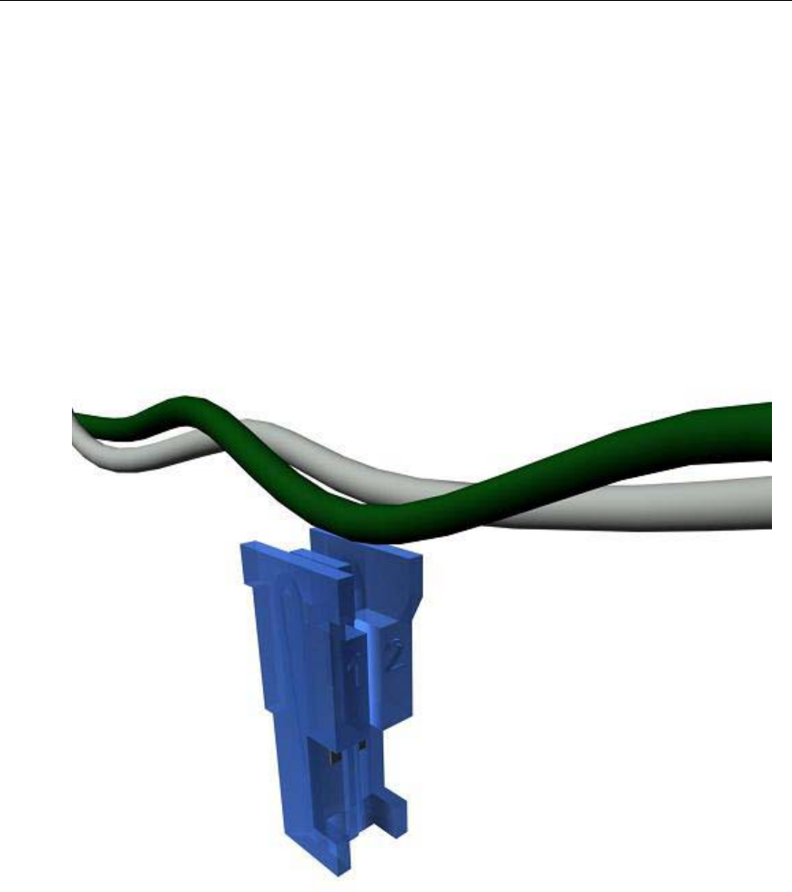
using the provided crimp tool. The figures below illustrate this procedure.
Figure 2.1.1: LED cable and LED connector
The first step in attaching a connector to the LED cable is to line up the
cable so that the colored wire on the cable is positioned over the socket
11
labeled with the number “1”. The uncolored wire should be positioned over
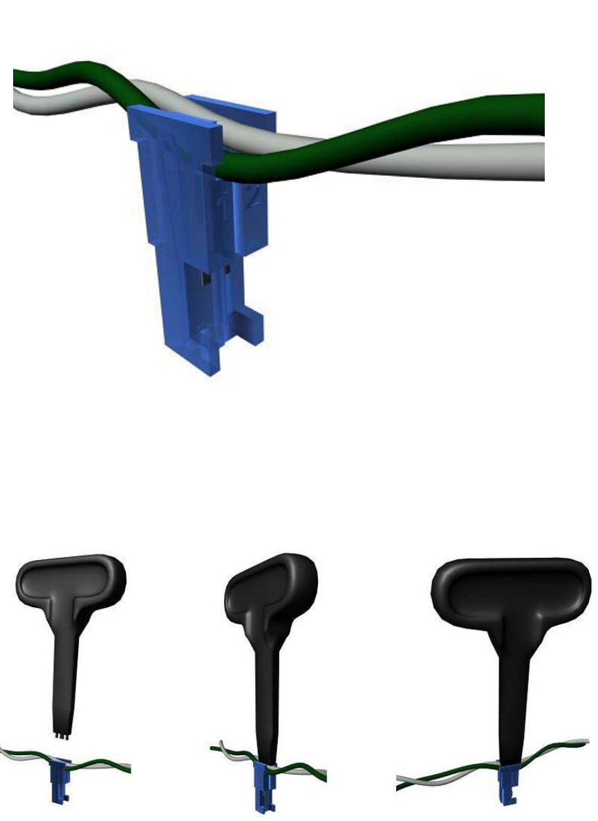
the socket labeled with the number “2” (refer to Figures 2.1.1 and 2.1.2).
Figure 2.1.2: LED cable positioned in LED connector
Each of the cable wires should then be pushed into the sockets on the
connector using the crimp tool (refer to Figures 2.1.3 and 2.1.4). To do this
it is best to place the connector on a solid surface in the orientation
shown. The connector should be held with one hand (or held using pliers),
and the crimp tool should be held and pushed down with the other hand.
Figure 2.1.3: Attaching of connector to LED cable using crimp tool
12
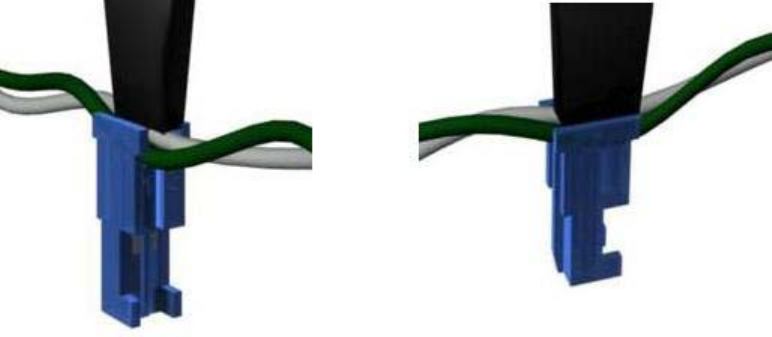
It is important that the wires be pushed fully into the teeth of the connector
sockets. This may require more than one push using the crimp tool.
Figure 2.1.4: Close-up of crimp tool and connector
The number of connectors necessary for a cable equal the number of LED
modules to be attached to the cable plus one connector that is required to
connect to the LED driver. Splitter connectors may be needed if string
branching is desired.
13

3: LED System Setup
The placement and number of LEDs used will depend on the nature of the
target that is to be tracked. For example, full body motion is tracked best by
placing LEDs along the legs, arms, head, and torso. Full body motion
requires the attaching of numerous LEDs (PhaseSpace recommends at
least 30 for full body motion) to be properly tracked. Other targets such as
the end of a bat or golf club may require only one LED.
3.1 LED Hardware Setup
The components of the LED system that are described in section 1 are
connected as follows:
• The LED Base Station is connected to the HUB/Server by
connecting one end of an ethernet cable to a port on the HUB and
the other end of the cable to the ethernet port on the LED Base
Station.
IMPORTANT NOTE: Never connect the LED Base Station to the
HUB while the HUB / server computer is on. Always make sure
that the HUB / server computer is off before connecting the LED
Base Station to the HUB.
• The LED Modules are attached to the LED Strings using the
string’s connectors. Each LED Module has a label that indicates the
LED’s designation. The labels are: A, B, C, D, E, F, G, H, I, J, K, L.
IMPORTANT NOTE: Two or more LEDs with the same
designation cannot be on one string. For example, two or more
LEDs labeled “A” must not be on the same string.
• The LED Strings connect to the 14-pin connector on the LED Driver
Unit (using the six-pin wire breakout or the six-port breakout box). In
the case of un-tethered operation, the driver unit should be
positioned for optimal signal reception. For example, for full body
motion capture placing the unit upside down on the shoulder blade is
better than placing the unit in the middle of the back.
14
• In un-tethered (RF) mode there is no physical connection between
the driver unit and base station In tethered mode, the LED Driver
Unit is connected to the LED Base Station using a 6-pin cable
between the 6-pin connectors on the driver unit and base station.
3.2 LED String File Setup
Customizing the LED string file is optional, but is recommended especially
when using more than one LED driver. The default file setup assumes that
each LED string has 8 LEDs. Thus, in a setup that contains six LED strings
to be tracked, the number of markers that would have to be entered in a
client such as the Master Control Client would have to be 48.
In order to optimize CPU usage, the LED string file can be setup so that the
number of markers that need to be tracked equals the actual number of
LEDs on the strings. The content of the strings file is accessed from the
LED configuration page of the PhaseSpace Configuration Manager (refer
to the PhaseSpace Impulse: Configuration Manager document).
6:ABCDEFGH
7:ABCDEFGH
8:ABCDEFGH
9:ABCDEFGH
10:ABCDEFGH
11:ABCDEFGH
12:ABCDEFGH
13:ABCDEFGH
14:ABCDEFGH
15:ABCDEFGH
16:ABCDEFGH
17:ABCDEFGH
The number on the left side of the colon is the port number while the letters
represent LED designations. The entries for the first six ports (0-5) are
reserved for the LED Base Station and are not included in this file. Ports 6
through 11 represent the information for the first driver unit, while ports 12
through 17 represent the information for a second driver unit. Additional
entries would be necessary in the case of more driver units.
It is best to look at an example to illustrate how to customize the LED string
file. Take, for instance, a single LED driver unit setup with six LED strings
connected to the driver unit. The first string has LEDs labeled A, B, C, D.
The second string has LEDs labeled E, F, G, H, A. The third string has
LEDs labeled B, C, D, E, F, G, H. The fourth string has LEDs labeled I, J, K,
L. The fifth string has LEDs labeled A, B, C, D, E, and the sixth string has
15
LEDs labeled F, G, H, I, J. In such a case, the strings file can be modified
(edited and saved) to look like:
6:ABCD
7:EFGHA
8:BCDEFGH
9:IJKL
10:ABCDE
11:FGHIJ
12:ABCDEFGH
13:ABCDEFGH
14:ABCDEFGH
15:ABCDEFGH
16:ABCDEFGH
17:ABCDEFGH
Notice that the entries representing ports 6 through 11 match the manner in
which the strings on the driver unit are populated. After modification the file
should be saved and the LED encoding command must be run (this is done
by clicking on the “encode” button on the LED configuration page of the
PhaseSpace Configuration Manager). The advantage of this particular
setup over the default is that the software has specific information about the
LED setup and the number of markers that need to be specified will be
equal to the actual number of LEDs on the strings (in this case 30).
If there subsequent changes to the physical LED configuration, then it
would be necessary to again modify the strings file accordingly.
16
