Philio Technology PAB01 Smart Energy In Wall Meter User Manual
Philio Technology Corporation Smart Energy In Wall Meter
Users Manual
PAB01 Smart Energy In Wall Meter
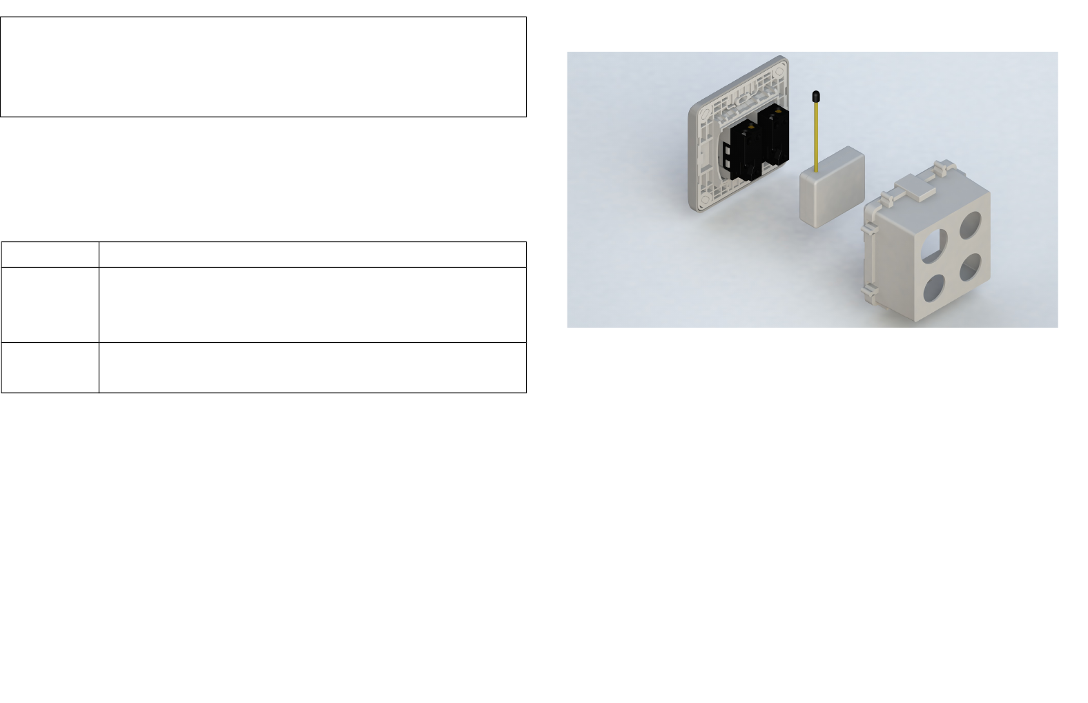
Fig 1. Assembling
Fig 2. Assembling
This dual meter module is a transceiver which is a Z-WaveTM enabled device and is
fully compatible with any Z-WaveTM enabled network. Mini size design let the
module can easily hide itself into the electricity distribution box and that will be good
for the house decoration.
This dual meter module is able to detect Instant power wattage (13800W/230Vac)(60
Amperes) of connected light or appliances.
Adding to Z-WaveTM Network
In the front casing, there is an on/off button with LED indicator below which is used to
carry out inclusion, exclusion, reset or association. After being excluded, its LED
flashes on and off alternately and repeatedly at 2-second intervals. It implies that it
has not been assigned a node ID and cannot work with Z-Wave enabled devices.
Auto Inclusion
The function of auto inclusion will be executed as long as the meter does not
have Node ID and just connect the meter to main power. When first power is applied,
its LED flashes on and off alternately and repeatedly at 0.5 second intervals. It
implies that it is in leaning mode now.
Note: Auto inclusion timeout is 2 minute during which the node information of explore
frame will be emitted once every 5 seconds. Unlike “inclusion” function as shown in
the table below, the execution of auto inclusion is free from pressing the On/Off
button on the meter.
The table below lists an operation summary of basic Z-Wave functions. Please refer
to the instructions for your Z-WaveTM Certificated Primary Controller to access the
Setup function, and to include/exclude/associate devices
Function Description LED Indication
No node ID The Z-Wave Controller does not allocate 2-second on, 2-second off
a node ID to the meter.
Inclusion 1. Have Z-Wave Controller entered
inclusion mode.
One press one flash
2. Pressing INCLUDE_BUTTON three
times within 2 seconds will enter
inclusion mode.
Exclusion 1. Have Z-Wave Controller entered
exclusion mode.
One press one flash
2. Pressing INCLUDE_BUTTON three
times within 2 seconds will enter
exclusion mode.
Node ID has been excluded. 2-second on, 2-second off
Reset 1. Pressing INCLUDE_BUTTON three
times within 2 seconds will enter
inclusion mode.
One press one flash
2. Within 1 second, press and hold
INCLUDE_BUTTON button again
for 5 seconds until LED is off.
3. IDs are excluded.
Association 1. Have Z-Wave Controller entered
association mode.
Or Pressing INCLUDE_BUTTON three
times within 2 seconds will enter
association mode
One press one flash
2. There are 3 groups for the meter
※Including a node ID allocated by Z-Wave Controller means inclusion. Excluding a node
ID allocated by Z-Wave Controller means exclusion.
※Failed or success in including/excluding the node ID can be viewed from the Z-Wave
Controller.
LED Indication
To distinguish what mode the meter is in, view from the LED for identification.
State Type LED Indication
No node ID Under normal operation, when the meter has not been allocated a
node ID, the LED flashes on and off alternately at 2 seconds
intervals.
Learning When PAB01 is in learning mode, LED flashes on and off
alternately and repeatedly at 0.5 second intervals.
Choosing a Suitable Location
1. Do not locate the meter facing direct sunlight, humid or dusty place.
2. The suitable ambient temperature for the Switch is 0°C~40°C.
3. Do not locate the meter where exists combustible substances or any source of
heat, e.g. fires, radiators, boiler etc.
4. After putting it into use, the body of meter will become a little bit hot of which
phenomenon is normal.
Installation
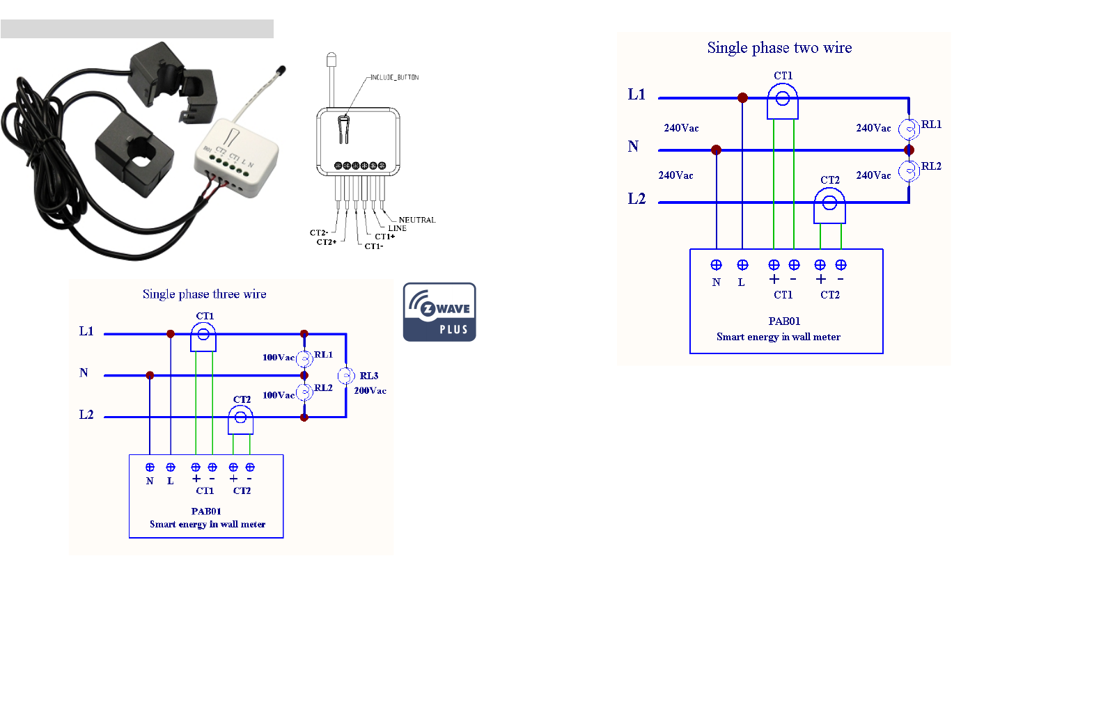
1. Put the in wall switch into a wall box and connect the AC power wire L,N to
PAB01 connector L, N.
2. The black wire of current sensor, CT1 or CT2, should connected to the negative
terminal of PAB01,CT1- or CT2-. Another wire should connected to the plus
terminal of PAB01,CT1+ or CT1+.
3. There is a clasp on the side of the current sensor, it can lock or unlock the clamp.
It is convenient to circle the already connected cable.

Programming
,
1. Z-Wave’s Groups (Association Command Class Version 2)
The meter can be set to send reports to associated Z-Wave devices. It supports 3
association groups which every group has one node support. Group1~Group3
support METER_REPORT_COMMAND_V3
For group 1, the Switch will report (1) The sum of instant Power Consumption (Watt)
read from CT1 and CT2 (2) The sum of accumulated Power Consumption (KWh)
read from CT1 and CT2.
For group 2, the Switch will report (1) Instant Power Consumption (Watt) read from
CT1 (2) Accumulated Power Consumption (KWh) read from CT1.
For group 3, the Switch will report (1) Instant Power Consumption (Watt) read from
CT2 (2) Accumulated Power Consumption (KWh) read from CT2.
2-1 Auto report to Grouping 1 ~3 (Maximum Node 1 per Group)
2-1-1 Instant Power Consumption vary over 5% report
When the instant power consumption read from CT1 or CT2 vary over 5%, it will
send Meter report to the nodes of Group
2-2 Response to Meter Get Command
The Switch will report its (1) instant Power Consumption (Watt) or (2) accumulated
power consumption(KWH) or (3) AC input Voltage (V) or (4) AC load current ( I )
(5) load power factor (PF) to Z-Wave Controller after receive the Meter Get
Command from Z-Wave Controller.
2-2-1 Instant Power Consumption (Watt)
When receiving Meter Get Command, it will report Meter Report Command to the
node asked.
Meter Get Command: [Command Class Meter, Meter Get, Scale =0x02(W)]
Meter Report Command: [Command Class Meter,Meter Report,scale(bit
2) +Rate Type +Meter Type,Precision + Scale(bit 1,0)+ Size,Meter
Value 1,Meter Value 2,Meter Value 3,Meter Value 4]
Rate Type = 0x01
Meter Type = 0x01
Precision = 1
Scale = 0x02(W)
Meter Report Command: [Command Class Meter,Meter
Report,scale(bit 2) +Rate Type +Meter Type,Precision + Scale(bit
1,0)+ Size,Meter Value 1,Meter Value 2,Meter Value 3,
Meter Value
4]

Size = 4 Bytes (Meter Value)
Meter Value 1 = (W) MSB
Meter Value 2 = (W)
Meter Value 3 = (W)
Meter Value 4 = (W)LSB
Example:
Meter Value 1 = 0x00 (W)
Meter Value 2 = 0x00 (W)
Meter Value 3 = 0x03 (W)
Meter Value 4 = 0xEA (W)
Meter(W) = Meter Value 3 *256 + Meter Value 4 = 100.2W
2-2-2 Accumulated Power Consumption (KW/h)
When receiving Meter Get Command, it will report Meter Report Command to
the node asked.
Meter Get Command: [Command Class Meter, Meter Get, Scale = 0x00
KW/h)]
Rate Type = 0x01
Meter Type = 0x01
Precision = 2
Scale = 0x00 (KWh)
Size = 4 bytes (Meter Value)
Meter Value 1 = (KWh) MSB
Meter Value 2 = (KWh)
Meter Value 3 = (KWh)
Meter Value 4 = (KWh) LSB
Example:
Scale = 0x00 (KWh)
Precision = 2
Size = 4 Bytes (KW/h)
Meter Value 1 = 0x00(KWh)
Meter Value 2 = 0x01(KWh)
Meter Value 3 = 0x38(KWh)
Meter Value 4 = 0xA3(KWh)
Accumulated power consumption (KW/h) = (Meter Value 2*65536) + (Meter Value
3*256) + (Meter Value 4) = 800.35 (KW/h)
2-2-3 Clearing accumulated power consumption
Meter Reset Command: [Command Class Meter, Meter Reset]
2-2-4 AC input Voltage (V)
Meter Report Command: [Command Class Meter,Meter
Report,scale(bit 2) +Rate Type +Meter Type,Precision + Scale(bit
1,0)+ Size,Meter Value 1,Meter Value 2,Meter Value 3,
Meter Value
4]
When receiving Meter Get Command, it will report Meter Report Command to the
node asked.
Meter Get Command: [Command Class Meter, Meter Get, Scale =0x04(V)]
Rate Type = 0x01
Meter Type = 0x01
Precision = 1
Scale = 0x04(V)
Size = 2 Bytes (Meter Value)
Meter Value 1 = High Byte (V)
Meter Value 2 = Low Byte (V)
Example:
Scale = 0x04 (V)
Precision = 1
Size = 2 (2 Bytes of V)
Meter Value 1 = 0x09(V)
Meter Value 2 = 0x01(V)
AC load Voltage = (Meter Value 1*256) +(Meter Value 2)= 230.5 (V)
2-2-5 AC load current ( I )
When receiving Meter Get Command, it will report Meter Report Command to the
node asked.
Rate Type = 0x01
Meter Type = 0x01
Precision = 2
Scale = 0x05(I)
Size = 2 Bytes (Meter Value)
Meter Value 1 = High Byte (I)
Meter Value 2 = Low Byte (I)
Example:
Scale = 0x05 (I)
Precision = 2
Size = 2 (2 Bytes of I)
Meter Value 1 = 0x01(I)
Meter Value 2 = 0x21(I)
Meter Report Command:
[Command Class Meter,Meter Report,scale(bit 2) +Rate Type +Meter
Type,Precision + Scale(bit 1,0)+ Size,Meter Value 1,Meter Value 2]
Meter Get Command: [Command Class Meter, Meter Get, Scale =0x05(I)]
Meter Report Command:
[Command Class Meter,Meter Report,scale(bit 2) +Rate Type +Meter
Type,Precision + Scale(bit 1,0)+ Size,Meter Value 1,Meter Value 2]
AC load current = (Meter Value 1*256) +(Meter Value 2)= 2.89 (A)
2-2-6 load power factor (PF)
When receiving Meter Get Command, it will report Meter Report Command to the
node asked.
If the value of configuration parameter 3 is 1, it will report the power factor of CT1,
but not the sum of PF of CT1 and CT2.
Rate Type = 0x01
Meter Type = 0x01
Precision = 2
Scale = 0x06(PF)
Size = 1 Bytes
Meter Value 1
Example:
Scale = 0x06 (PF)
Precision = 2
Size = 1 (1 Byte of PF)
Meter Value 1 = 0x63(PF)
Load power factor (PF) = Meter Value 1 =0.99
2-3 Multi Channel Command Class Version 3
PAB01 also support muti channel command class(version 3) , which include
METER_SUPPORTED_GET, METER_RESET,METER_GET.
You may get report from 3 endpoint of PAB01
2-3-1 METER_SUPPORTED_GET:
This command is to ask the endpoint of PAB01 what kind of meter data can be
reported
The example show how to get the meter report type
COMMAND_CLASS_MULTI_CHANNEL
MULTI_CHANNEL_CMD_ENCAP
Source End Point = 0x01 (this is the endpoint of command owner
here we assume endpoint is 1,if the
owner doesn’t support multi Channel this
value will be 0)
(Bit Address+Destination End Point = 0x03) (Bit Address =0;Destination End Point
range1~3)
Command Class = 0x32 ( Command_Class_Meter_V3 = 0x32)
Command =0x03 (Meter_Supported_Get = 0x03)
Below is the example show PAB01 report to last command
Meter Get Command: [Command Class Meter, Meter Get, Scale =0x06(PF)]
Meter Report Command:
[Command Class Meter,Meter Report,scale(bit 2) +Rate Type +Meter
Type,Precision + Scale(bit 1,0)+ Size,Meter Value 1]

COMMAND_CLASS_MULTI_CHANNEL
MULTI_CHANNEL_CMD_ENCAP
Source End Point = 0x03
(Bit Address+Destination End Point = 0x01)
Command Class = 0x32 (Command_Class_Meter_V3 = 0x32)
Command =0x04 (Meter_Supported_Report = 0x04)
Parameter 1 = 0x81 (Meter Reset =1 , Meter Type=0x01)
Parameter 2 = 0x75 (Scale Supported =
KWh+W+V+A+Power Factor = 0x75)
2-3-4 METER_RESET
This command is to reset the Accumulated Power Consumption (KWh) to 0
The example show how to reset the KWh
COMMAND_CLASS_MULTI_CHANNEL
MULTI_CHANNEL_CMD_ENCAP
Source End Point = 0x03 (this is the endpoint of command owner,
here we assume endpoint is 3,if the
owner doesn’t support multi Channel this
value will be 0)
(Bit Address+Destination End Point = 0x01) (Bit Address =0;Destination End Point
range1~3)
Command Class = 0x32 ( Command_Class_Meter_V3 = 0x32)
Command =0x05 ( Meter_Reset = 0x05)
2-3-5 METER_GET:
Using meter get command to get the KWH,W,V,I,PF from endpoint of PAB01
2-3-5-1 Get KWH from endpoint
Meter_GET example:
COMMAND_CLASS_MULTI_CHANNEL
MULTI_CHANNEL_CMD_ENCAP
Source End Point = 0x05 (this is the endpoint of command owner,
here we assume endpoint is 5,if the
owner doesn’t support multi Channel this
value will be 0)
(Bit Address+Destination End Point = 0x03) (Bit Address =0;Destination End Point
range1~3)
Command Class = 0x32 ( Command_Class_Meter_V3 = 0x32)
Command =0x01 (Meter_Get = 0x01)
Parameter 1 = 0x00 (Scale = KWH = 0x00)
Accumulated power consumption (KWH) Report example:
COMMAND_CLASS_MULTI_CHANNEL
MULTI_CHANNEL_CMD_ENCAP
Source End Point = 0x03 (Meter report = Endpoint3)
(Bit Address+Destination End Point = 0x05) (Bit Address =0;Destination End Point =
command owner Endpoint value)
Command Class = 0x32 (Command_Class_Meter_V3 = 0x32)
Command =0x02 (Meter_Report = 0x02)
Parameter 1 = 0x21 (Scale Bit2 = 0 ,Rate Type = 0x01,
Meter Type=0x01)
Parameter 2 = 0x44 (Precision = 2,Scale Bit1Bit0 = 0,Size
= 4)
Parameter 3 = 0x00 Accumulated Power Consumption =
0x000005FD = 15.33 KWh
Parameter 4 = 0x00
Parameter 5 = 0x05
Parameter 6 = 0xFD
2-3-5-2 Get Instant Power Consumption (Watt) from endpoint
METER_GET example:
COMMAND_CLASS_MULTI_CHANNEL
MULTI_CHANNEL_CMD_ENCAP
Source End Point = 0x05 (this is the endpoint of command owner,
here we assume endpoint is 5,if the owner
doesn’t support multi Channel this value will
be 0)
(Bit Address+Destination End Point =
0x03)
(Bit Address =0;Destination End Point
range 1~3)
Command Class = 0x32 ( Command_Class_Meter_V3 = 0x32)
Command =0x01 (Meter_Get = 0x01)
Parameter 1 = 0x10 (Scale = W = 0x02)
PAB01 Instant Power Consumption (W) Report example:
COMMAND_CLASS_MULTI_CHANNEL
MULTI_CHANNEL_CMD_ENCAP
Source End Point = 0x03 (Meter report = Endpoint3)
(Bit Address+Destination End Point = 0x05) (Bit Address =0;Destination End Point =
command owner Endpoint value)
Command Class = 0x32 (Command_Class_Meter_V3 = 0x32)
Command =0x02 (Meter_Report = 0x02)
Parameter 1 = 0x21 (Scale Bit2 = 0 ,Rate Type = 0x01,
Meter Type=0x01)
Parameter 2 = 0x34 (Precision = 1,Scale Bit1Bit0 =
0x02,Size = 4)
Parameter 3 = 0x00
Instant Power Consumption =
0x000003EA
= 100.2W
Parameter 4 = 0x00
Parameter 5 = 0x03
Parameter 6 = 0xEA
2-3-5-3 Get load voltage V from endpoint
Meter_GET example:
COMMAND_CLASS_MULTI_CHANNEL
MULTI_CHANNEL_CMD_ENCAP
Source End Point = 0x05 (this is the endpoint of command owner,
here we assume endpoint is 5,if the owner
doesn’t support multi Channel this value will
be 0)
(Bit Address+Destination End Point =
0x03)
(Bit Address =0;Destination End Point
range1~3)
Command Class = 0x32 ( Command_Class_Meter_V3 = 0x32)
Command =0x01 (Meter_Get = 0x01)
Parameter 1 = 0x20 (Scale = V = 0x04)
PAB01 AC input Voltage report example:
COMMAND_CLASS_MULTI_CHANNEL
MULTI_CHANNEL_CMD_ENCAP
Source End Point = 0x03 (Meter report = Endpoint3)
(Bit Address+Destination End Point = 0x05) (Bit Address =0;Destination End Point =
command owner Endpoint value)
Command Class = 0x32 (Command_Class_Meter_V3 = 0x32)
Command =0x02 (Meter_Report = 0x02)
Parameter 1 = 0xA1 (Scale Bit2 = 1 ,Rate Type = 0x01,
Meter Type=0x01)
Parameter 2 = 0x22 (Precision = 1,Scale Bit1Bit0 =
0x00,Size = 2)
Parameter 3 = 0x09 Voltage = 0x0910 = 232.0V
Parameter 4 = 0x10
2-3-5-4 Get load current I from endpoint
Meter_GET example:
COMMAND_CLASS_MULTI_CHANNEL
MULTI_CHANNEL_CMD_ENCAP
Source End Point = 0x05 (this is the endpoint of command owner,
here we assume endpoint is 5,if the owner
doesn’t support multi Channel this value will
be 0)
(Bit Address+Destination End Point =
0x03)
(Bit Address =0;Destination End Point
range1~3)
Command Class = 0x32 ( Command_Class_Meter_V3 = 0x32)
Command =0x01 (Meter_Get = 0x01)
Parameter 1 = 0x28 (Scale = A = 0x05)
PAB01 AC input current (I) example:
COMMAND_CLASS_MULTI_CHANNEL
MULTI_CHANNEL_CMD_ENCAP
Source End Point = 0x03 (Meter report = Endpoint3)
(Bit Address+Destination End Point = 0x05) (Bit Address =0;Destination End Point =
command owner Endpoint value)
Command Class = 0x32 (Command_Class_Meter_V3 = 0x32)
Command =0x02 (Meter_Report = 0x02)
Parameter 1 = 0xA1 (Scale Bit2 = 1 ,Rate Type = 0x01,
Meter Type=0x01)
Parameter 2 = 0x4A (Precision = 2,Scale Bit1Bit0 =
0x01,Size = 2)
Parameter 3 = 0x00 Current = 0x002B = 0.43A
Parameter 4 = 0x2B
2-3-5-5 Get power factor PF from endpoint
Meter_GET example:
COMMAND_CLASS_MULTI_CHANNEL
MULTI_CHANNEL_CMD_ENCAP
Source End Point = 0x05 (this is the endpoint of command owner,
here we assume endpoint is 5,if the owner
doesn’t support multi Channel this value will
be 0)
(Bit Address+Destination End Point =
0x03)
(Bit Address =0;Destination End Point
range1~3)
Command Class = 0x32 ( Command_Class_Meter_V3 = 0x32)
Command =0x01 (Meter_Get = 0x01)
Parameter 1 = 0x30 (Scale = PF = 0x06)
PAB01 power factor report example:
COMMAND_CLASS_MULTI_CHANNEL
MULTI_CHANNEL_CMD_ENCAP
Source End Point = 0x03 (Meter report = Endpoint3)
(Bit Address+Destination End Point =
0x05)
(Bit Address =0;Destination End Point =
command owner Endpoint value)
Command Class = 0x32 (Command_Class_Meter_V3 = 0x32)
Command =0x02 (Meter_Report = 0x02)
Parameter 1 = 0xA1 (Scale Bit2 = 1 ,Rate Type = 0x01,
Meter Type=0x01)
Parameter 2 = 0x51 (Precision = 2,Scale Bit1Bit0 = 0x10,Size
= 1)
Parameter 3 = 0x63 Power Factor = 0x63 = 0.99
Note : If the Destination End Point is 1, it will report the power factor of CT1, but not
the sum of PF of CT1 and CT2.
3.Z-Wave’s Configuration
Configuration
Parameter
Function Size
(Byte)
Value Unit Default Description
1 Watt
Meter
Report
Period
2 0x01-
0x7FFF
5s 720 5*720s=3600s=1
hour
2 KWH 2 0x01- 5s 720 5*720s=3600s=1
Meter
Report
Period
0x7FFF hour
3 Slected
End Point
1 1-3 1 1:CT1 and CT2
2:CT1
3:CT2
4 Threshold
of Current
for Load
Caution
2 10-750 0.01A 750 750*0.01A=7.5A
5 Threshold
of KWH
for Load
Caution
2 1-10000 1KWh 10000
3-1 Watt Meter Report Period:
If the setting is configured for 1hour (set value =720), the PAB01 will report its
instant power consumption every 1 hour to the node of correspond Group. The
maximum interval to report its instant power consumption is 45 hours
(5s*32767/3600=45hr).
3-2 KWH Meter Report Period:
If the setting is configured for 1hour (set value =720), the PAB01 will report its
Accumulated Power Consumption (KW/h) every 1 hour to the node of correspond
Group. The maximum interval to report its Accumulated Power Consumption
(KW/h) is 45 hours (5s*32767/3600=45hr).
3-3 Selected Endpoint
If Controller not using Multi_Channel command class to access the endpoint of
PAB01, you may configure the endpoint value to react the Basic Command Class
、Binary Switch Command Class or Meter Command Class V3
3-3-1 Selected Endpoint 1: Default Selected Endpoint is 1
Get command parameter Report to command sender
Meter_Get KWh CT1 KWh1+CT2 KWh2
Meter_Get Watt CT11 W1+CT2 W2
Meter_Get Voltage CT1 and CT2 are the same voltage
Meter_Get Current CT1 I1+CT2 I2
Meter_Get Power factor PF CT1
3-3-2 Selected Endpoint 2
Similar like Selected Endpoint 1 but only relate to CT1 and ignore CT2
3-3-3 Selected Endpoint 3
Similar like Selected Endpoint 1 but only relate to CT2 and ignore CT1
3-4 Threshold of Current for Load Caution
This is a warning when the current of load over the preset threshold value, If the
setting value is 750, when the load wattage of CT1 or CT2 over 7.5A, PAB01 will
send current Meter Report command to the node of correspond Group.
3-5 Threshold of KWh for Load Caution
This is a warning when the KWh of load over the preset threshold value, If the setting
value is 10000, when the Accumulated Power Consumption of CT1 or CT2 over this
value, PAB01 will send KWh Meter Report command to the node of correspond
Guoup, minum value is 1KWh and default value is 10000 kWh
4. Command Classes
The Switch supports Command Classes including…
* COMMAND_CLASS_ZWAVEPLUS_INFO
* COMMAND_CLASS_VERSION
* COMMAND_CLASS_MANUFACTURER_SPECIFIC_V2
* COMMAND_CLASS_DEVICE_RESET_LOCALLY
* COMMAND_CLASS_ASSOCIATION_V2
* COMMAND_CLASS_ASSOCIATION_GRP_INFO
* COMMAND_CLASS_POWERLEVEL
* COMMAND_CLASS_MULTI_CHANNEL_V3
* COMMAND_CLASS_METER_V3
* COMMAND_CLASS_CONFIGURATION
Troubleshooting
Symptom Cause of Failure Recommendation
The meter is not working
and LED off
1. The meter is not
connect to the Main
power
2. The meter break down
1. Check power connections
2. Don’t open up the meter and send it
for repair.
The meter cannot report to
the group
1. Not carry out
association
2. Same frequency
interference
1. Carry out association
2. Wait for a while to re-try
Specification
Operating Voltage 100~240VAC
Rated Primary Current 0.05A~60A x 2 Channel ; Split Core Transformer
Range Minimum 40 m in door 100m outdoor line of sight
Operating Temperature 0°C ~ 40°C
Frequency Range PAB01-1 868.40 & 869.85MHz (EU) /
PAB01-2 908.40 & 916.0MHz(USA/Canada) /
PAB01-3 922~927MHz (Taiwan/JP)
** Specifications are subject to change and improvement without notice.
FCC ID : RHHPAB01
DANGER
Danger of electrocution!
All works on the device may be performed only by a qualified and licensed
electrician. Observe national regulations.
Any works introducing changes into the configuration must be always performed with
disconnected voltage.
Choosing a Suitable Location
1. Do not locate the Module facing direct sunlight, humid or dusty place.
2. The suitable ambient temperature for the Module is 0°C~40°C.
3. Do not locate the Module where exists combustible substances or any source of
heat, e.g. fires, radiators, boiler etc.
4. After putting it into use, the body of Module will become a little bit hot of which
phenomenon is normal.
