Philio Technology PAN27 Smart Home DIN Rail box User Manual PAN27 manual 20180613
Philio Technology Corporation Smart Home DIN Rail box PAN27 manual 20180613
User Manual
1
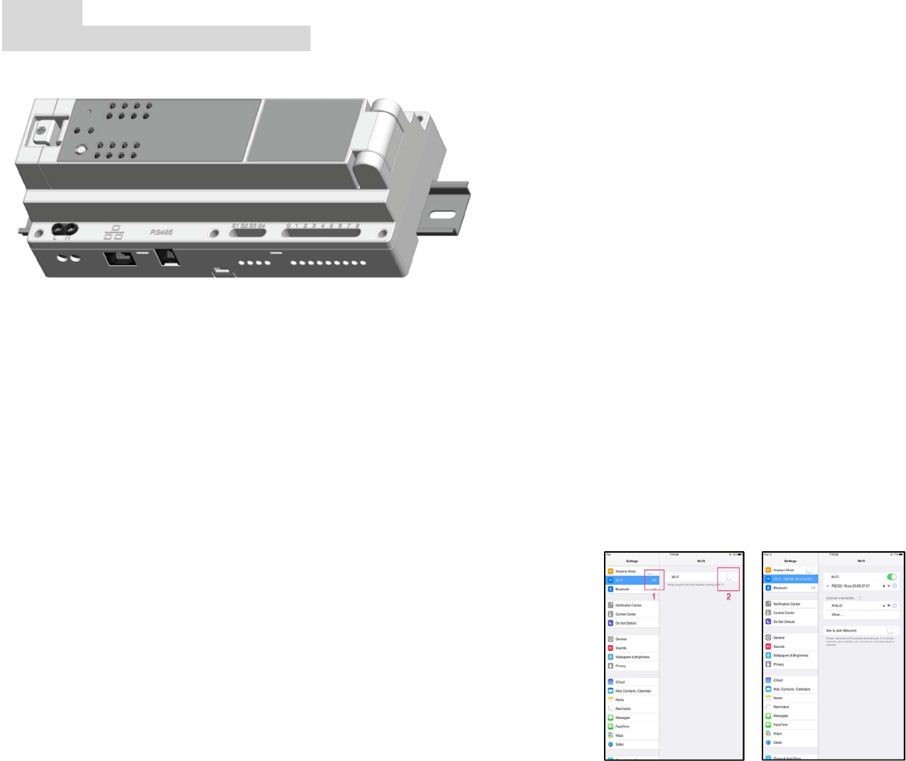
PAN27
Smart Home DIN Rail box
Note: The power cord must meet 1.25mm² or 16AWG or better
This Smart home din rail mounted box with dongles is “simply fabulous”
Smart home DIN rail box looks ok, but it’s really one lean mean machine
boasting 8 output slots that can control just about anything with plug n’
play dongles. The 8 outputs correspond to 8 inputs, so the unit can be
used from the start without programming. Four additional inputs can be
used to run scenarios without the app, and the input method can also be
easily changed from push button to switch.
• On/Off
• Dimmer
• Dry contact
Compatible with just about anything
By default Smart home din rail box communicates via RJ11 or RJ45 (WiFi). By simply
adding a dongle to one of the two USB ports, the box supports Z-Wave and ZigBee.
(
Note: For FCC ID: RHHPAN27, it supports WLAN 2.4G mode only without Z-Wave and
Zigbee function.)
A one-time installation of the all-in-one box ensures support and
compatibility with just about any system or device from any manufacturer.
Safety Precautions and Installation
• Disconnect from supply before removing
• Avoid installing the unit in storming or raining weather.
• Be sure to isolate or switch off power source before installing or
maintenance.
• Do ensure that the power supply circuit protected by a 16A circuit breaker or
suitable equivalent fuse.
• Make sure to protect each external power circuit 5A (relay dongle) by using
either circuit breaker or equivalent suitable fuse.
IMPORTANT
• Installation and any maintenance must be performed by skilled technicians
who are informed about the standards and technical requirements of the ap-
pliance and its proper installation. Installing or changing dongle shall also be
performed by skilled technicians. Disconnect from supply before any mainte-
nance or serving. The accessible parts to user is LED display plate after in-
stallation.
• Check your local codes as they apply to your situation. If the house wiring is
of aluminum, consult with an electrician about proper wiring methods.
Before proceeding with the installation, TURN OFF THE POWER TO THE LIGHTING
CIRCUIT AT THE CIRCUIT BREAKER OR FUSE BOX TO AVOID ELECTRICAL
SHOCK.
Security
Before making any connections, please read these instructions carefully.
Never remove the plastic base from DIN rail.
Do not touch live parts. High voltages present in module.
To access the interior of this equipment must first be disconnected from the mains.
Connect to the internet.
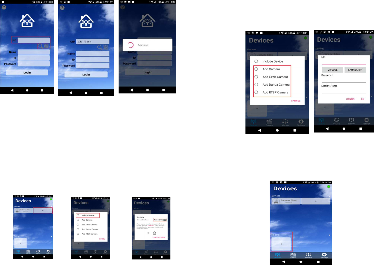
• Go to Settings, Wi-Fi, choose your own Wi-Fi SSID, and connect it.
• Once you connect to Wi-Fi, open the app
2
• Add UID: Can enter 10.10.10.254 or press Search or press QR Code to scan
the QR Code to set up the gateway address.
•Name: arbitrary input
• ID: admin
• Password: 888888
Add your devices
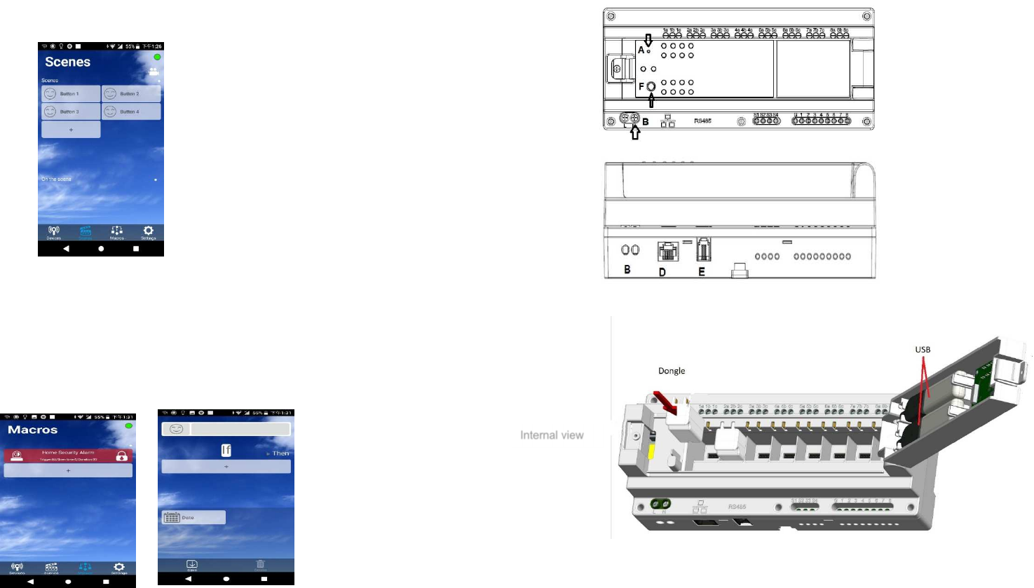
• In the Device page, press Plus Gear Include Device to add Z-wave or ZigBee
devices. (Remember to activate the include mode of your device by
flipping three times the trigger on it.)
Add IP Cam
• In the Divice page, press Plus Gear Add IP Cam QR Code to add
IP Cam by scanning the QR Code with camera.
Add a room
• Press Add new Room in the Device page to add a new room, enter the name of
the room as you like.
3
Scene
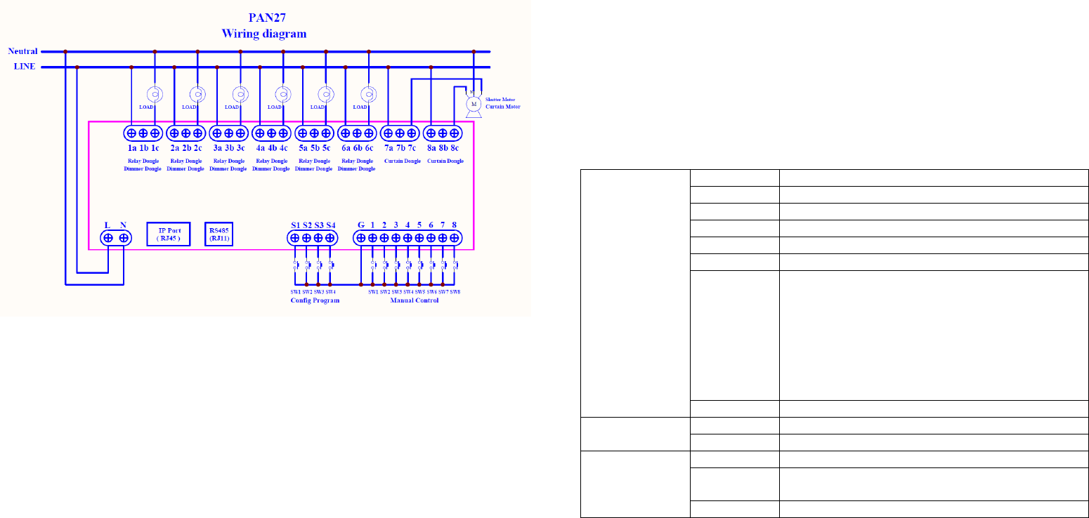
• Scene can set the room ambiance quickly. It can help you to have a
better experience at the special
moment.
Macro
Still worry about your flat security?
Macro is just like your 24-7 personal home guard.
It secures your flat. Just set the reactive you wishes, it obeys your orders faithfully.
Overview
Front view
Side view
A. Reset
B. AC Power input
D. RJ45 Ethernet port
E. RJ 22 port
F. Learn Key
Internal view
4
Wire Connection
To start using PAN27 Smart Home Relay/dimmer Box, please connect the device to
power and LAN sockets, as shown below.
Connect power cable to the mains, and network cable to LAN socket in your router
(PAN27 requires an outside router or you can only control the system at your home).
Communication setup
PAN27 is shipped with the following default parameters:
IP address: Assigned by DHCP
Login: admin
Web password: 888888
APP web
Installing the companion APP
1. Connect your phone to Internet, login or sign up for google account or APP ID
2. Launch Play store or APPLE store
3. Search for Philio’s Home Mate, then install the companion APP.
4. Click the APP and you can use local LAN search or QR code to find PAN27
5. Please use ID: admin password: 888888 to login the APP
6. The detail of APP, please see the APP manual.
Table of connections
Interface L-N AC100-240V
S1-S4 Control scenes
G
Ground
1~8
Control On/Off, Dimming,
RJ11 4P2C, for RS485 interface
RJ45 10/100 Base-T Ethernet
1a1b1c,
2a2b2c,
3a3b3c,
4a4b4c,
5a5b5c,
6a6b6c,
7a7b7c,
8a8b8c
For signal
USB For Z-wave, ZigBee dongle (operational)
Button Learn Key Z-wave include/exclude
Reset Reset to default
LED indicator Power ON/OFF
1-8 Indicate dongle status
(Relay/Dimmer dongles)
Net Net
5
The functions of PAN27:
::
:
1. PAN27 can install 8 independent Relay or Dimmer dongle and can hot plugin.
2. PAN27 can use Zigbee/Z wave USB Dongle (operational).
3. PAN27 can control the PAN26 with RJ11 and PAN27(set as slave).
4. PAN27 each relay dongle can bear current 5A
5. PAN27 each dimmer dongle can bear current 0.7A
The key on the body
TEMP key:
For safety issue, you must close the top cover and start to work. When you open the
cover, TEMP key will be trigger and all module will be off and cannot be controlled
until you close the cover.
Reset key:
You can reset all the PAN27 parameter include Z-Wave/Zigbee device by press by
press 5 seconds
The external Switch
Relay dongle can connect the wall switch as Edge/Pulse/Toggle mode
Each dongle can detect the loading. When detect is overload, the module switch will
be set to off and no more current.
About LED indicator, if no module, LED is off.
When the dongle with current, the LED will be on/green.
When the dongle without current, the LED will be off/red.
How to add the device
You can insert the dongle or use Zigbee/Z-Wave to add the device.
The dongle will show on main screen directly and you can press to do actions
like Relay on/off, Dimmer adjust moving.
If you are using Zigbee/Z-Wave device, you can press the + and set PAN27 into
inclusion mode the press the device temper key to add to PAN27.
The detail operation of the device, you should refer the manual of the device.
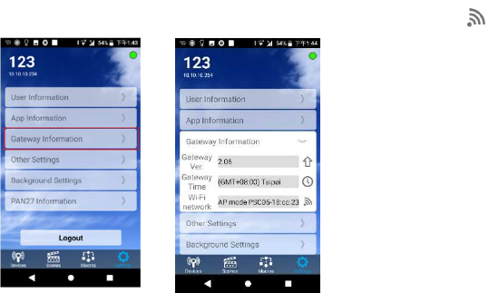
Gateway WIFI Setting
Go to Setting Tab and click “Gateway Information”, then press icon.
The default is AP mode and if you want use STA mode please do as step by step.
Programming
When installing the relay dongle, it is necessary to set it in groups of two and insert it
in the specified grouping position.
Ontology button:
TEMP key: In the normal working mode, the cover needs to be closed. For safety
reasons, when the cover is opened, the TEMP key will turn off the full
Module and will not accept any control until the cover is attached.
Learn key: press three times include / press five to exclude
Reset key: reset the set value
External Key Switch:
::
:
PAN27 can connect 12 groups of manual switches, which are 8 groups of control
switches and 4 groups of situational switches.
When the corresponding module of the control switch is the Relay Module, it can be
set to Edge mode, Pulse mode or Edge-Toggle mode. The Default value is Edge-
Toggle mode.

6
Edge mode:
::
:
Edge mode is suitable for switches that normally use a fixed position. When the
switch is held down, it can control Relay1 or Relay2 to be ON. When the switch is
held up, it can control Relay1 or Relay2 to OFF.
Pulse mode:
::
:
The Pulse mode is suitable for releasing the automatic pop-up switch. Pressing the
hand and then releasing the switch can toggle the Relay1 or Relay2 to ON (or OFF);
press the hand again to release the switch, and then toggle the Relay1 or Relay2 ON
again. OFF state; and so on.
Edge-Toggle mode:
::
:
The Edge-Toggle mode can only be used on switches that are normally fixed positions.
Toggle control of Relay1 or Relay2 is ON (or OFF) each time the switch is pressed
(being held or tilted); the hand is switched again (turned or pressed). , then again toggle
the ON/OFF state of Relay1 or Relay2; and so on.
Control switch:
Dongle action directions
RELAY Toggle mode When the switch has a switch, Relay will be anti-
action, ON become OFF, OFF become ON
Pulse mode When the switch is pressed once (Press →
Release),Relay will be anti-action, only press not
released
Edge mode When the switch is switched on, only Relay ON
action, when releasing, only the Relay OFF action
DIMMER Long press When the button is pressed for more than 1 second
and is not released, it is judged as a long press. The
dimmer will start dimming until the button is
released. The dimming will be stopped, and the
state will be stopped at the time of release.
Short press When the key is pressed within 1 second, one press
(press → release), it is judged as a short press. If
the current LEVEL is not 0%, it will be moved to 0%,
and the current LEVEL is 0%, then it will move to the
previous LEVEL.
Current Detection:
When the Module is in the normal working mode, it has a load detection function, that
is, detects the power load status of the Module.
When an "overload" condition is detected, the Module switch is immediately set to
“OFF” and the load power is permanently switched off.
In the overload condition, the Module no longer accepts the control (including the signal
of the Module button and the RF control ON), and must wait until the Device releases
the Error state caused by the overload and operates normally.
LED indicator:
General mode: When the Module enters the normal working mode, if there is a control
switch or RF command control module, the LED will show the Module state, when
there is electricity conduction, the state is ON green, the state is OFF when the power
is off. red light.
When no Module is installed in this position, the LED indicator is completely off.
POWER signal: When there is a normal power supply, the light is always on, and it
flickers when there is a network connection.
Connection Signal: When the connection status of PAN27 is Ready, the indicator will
keep on, and it will flash when entering the learning.
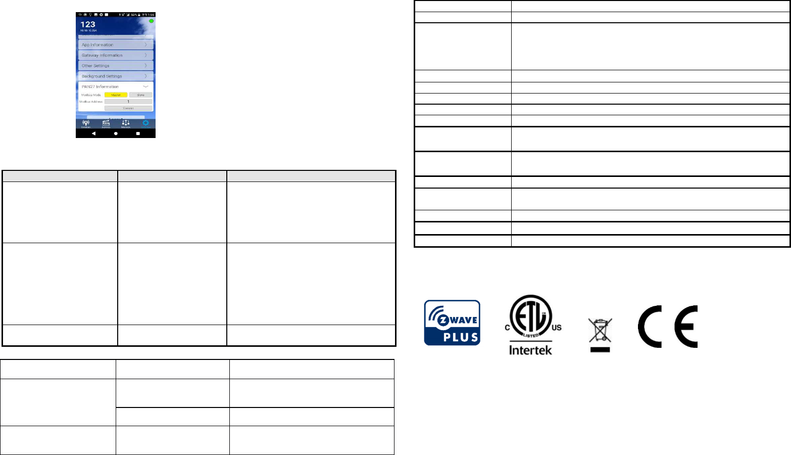
RJ11 (RS485) Control:
Using the MODBUS protocol
The default is master, you can use app be set to slave
When other slaves are connected, they will be automatically detected and include the
device
7
Troubleshooting
Symptom
Cause of Failure
Recommendation
The switch does not work
and the LED is off 1. The Switch is not
plugged into the
electrical outlet
properly
2. The Switch break
down
1. Check power connections
2. Don’t open up the Switch and send it
for repair.
The LED illuminates, but
cannot turn ON or OFF the
switch of the load attached
1. Check if the load
plugged into the Switch
has its own ON/OFF
switch
2. Not carry out
association
3. Same frequency
interference
1. Set the ON/OFF switch of the load
attached to ON
2. Carry out association
3.Wait for a while to re-try
LED keep flashing, but
cannot control Overload occurs
Remove the load attached or check max.
load cannot exceed 16.0A
Situation
Root cause
Solution
No LED indicator 1. No main power Please check the LN power line and
power outlet
2. PAN27 is broken
Please return to the vender.
LED is normal, but the
device is no action
Please make sure the
device has own switch
Please turn the device to On.
Specification
Operating Voltage
100-240VAC 50/60Hz 16A
Rated Voltage
AC100-240V 50Hz
Output Current Max.16A
Relay Dongle: 5A (model: ME001)
Dimmer Dongle: 0.7A (model: ME002)
8 independent relay or dimmer outputs
Maximum DC output
DC12V*8
Maximum AC output
16A
Range
Minimum 40 m in door and 100m outdoor; line of sight
Operating Temperature
0°C ~ 40°C (85% humidity)
Storage Temperature
-20 C ~ 60°C
interface RJ11 (4P2C) for RS485 interface
RJ45 10/100 base-T
USB port Z-wave 500 series Dongle (operational)
ZigBee Dongle (operational)
Location
Indoor use only
Frequency Range
IEEE 802.11 b/g/n
2412-2472MHz (EU), 2412-2462MHz (USA)
RF power
+17dBm
Di
mension
210 (L) x 90(W) x 78 (H) mm
Patent pending
** Specifications are subject to change and improvement without notice.
FCC ID: RHHPAN27
www.philio-tech.com
Philio Technology Corporation
8F., No.653-2, Zhongzheng Rd., Xinzhuang Dist., New Taipei City 24257, Taiwan
8
DANGER
Danger of electrocution!
All works on the device may be performed only by a qualified and licensed electri-
cian. Observe national regulations.
Any works introducing changes into the configuration must be always performed with
disconnected voltage.
Choosing a Suitable Location
1. Do not locate the Module facing direct sunlight, humid or dusty place.
2. The suitable ambient temperature for the Module is 0°C~40°C.
3. Do not locate the Module where exists combustible substances or any source of
heat, e.g. fires, radiators, boiler etc.
4. After putting it into use, the body of Module will become a little bit hot of which phe-
nomenon is normal.
Warning:
1. This device must be installed by qualified personnel;
2. This device must not be installed directly outdoors;
3. Installation consists of mounting the device, connecting to an IP network,
connecting the relays, providing power and configuring via a web browser.
Box mounting
Mounting the device to DIN rail
Smart Home DIN rail box can be mounted to a standard (210mm x 90mm x 78mm)
DIN rail. Attach the module to the DIN rail by hooking the hook on the back of the
enclosure to the DIN rail and then snap the bottom hook into place.
Disposal
1.
This marking indicates that this product should not be disposed with other
household wastes throughout the EU. To prevent possible harm to the
environment or human health from uncontrolled waste disposal, recycle it
responsibly to promote the sustainable reuse of material resources. To return
your used device, please use the return and collection systems or contact the
retailer where the product was purchased. They can take this product for
environmental safe recycling
FCC Interference Statement
This equipment has been tested and found to comply with the limits for a Class B digital
device, pursuant to Part 15 of the FCC Rules.
These limits are designed to provide reasonable protection against harmful interference in a
residential installation.
This equipment generates, uses and can radiate radio frequency energy and, if not installed
and used in accordance with the instructions, may cause harmful interference to radio
communications.
However, there is no guarantee that interference will not occur in a particular installation.
If this equipment does cause harmful interference to radio or television reception, which
can be determined by turning the equipment off and on, the user is encouraged to try to correct
the interference by one of the following measures:
• Reorient or relocate the receiving antenna.
• Increase the separation between the equipment and receiver.
• Connect the equipment into an outlet on a circuit different from that to which the receiver is
connected.
• Consult the dealer or an experienced radio/TV technician for help.
This device complies with Part 15 of the FCC Rules. Operation is subject
to the following two conditions:
(1) This device may not cause harmful interference, and
(2) This device must accept any interference received, including interference that may cause
undesired operation.
9
FCC Caution: Any changes or modifications not expressly approved by the party responsible
for compliance could void the user's authority to operate this equipment.
RF exposure warning
This equipment must be installed and operated in accordance with provided in-
structions and the antenna(s) used for this transmitter must be installed to provide
a separation distance of at least 20 cm from all persons and must not be co-located
or operating in conjunction with any other antenna or transmitter. End-users and in-
stallers must be provide with antenna installation instructions and transmitter oper-
ating conditions for satisfying RF exposure compliance.