Philips Electronics M114 19 Inches Color Monitor User Manual
Philips Electronics Industries (Taiwan) Ltd 19 Inches Color Monitor
User Manual

Product Information
Product Features • LightFrame™ for Windows •Technical Specifications • Automatic
Power Saving • Physical Specification • Pin Assignment • Product Views
Product Features
109B40/109B43:
19-inch (18.0" VIS) Real Flat color monitor with excellent front of screen performance for use
with MACs and PCs
Autoscan covers horizontal frequencies up to 90 kHz offering a maximum resolution of 1920 x
1440 with flicker free display of 1280 x 1024 at up to 91 Hz
Real Flat High Contrast CRT with high-resolution 0.25 mm dot pitch (0.21 hdp)
LightFrame™ for brightest and sharpest display of movie and photo windows
XSD-Xtra Space Design for large screen display in a small footprint: World's shortest 19" Real
Flat shadow mask monitor with maximum depth of only 449 mm/17.6" that matches most of
today's 19-inch monitors
Multimedia Base and USB Hub option
sRGB for true on screen color representation.
FCC, CE (in selected countries only) and ISO9241, ISO14001 certified
RETURN TO TOP OF THE PAGE
LightFrame™ for Windows
Introduction
Philips LightFrame™ feature enriches the experience of pictures and video on a Philips CRT (picture
tube) monitor. LightFrame™ will boost the brightness and sharpness of photos and videos on the
monitor screen.
To control the LightFrame™ feature in your monitor, you have to install the LightFrame™ application
which you will find on this CD-ROM.
Note
Philips LightFrame™ will only work with monitors that have been built to use this software. Earlier
Philips monitors or other manufacturers’ monitors will not work with this special software. It is
recommended that you install this software only on a Philips monitor designed to use it. These monitors
can be identified by the LightFrame™ logo on the front of the monitor.
This software is not designed for use with LCD flat screen monitors.
LightFrame™ will work with true Windows-based programs and DOS-based programs that operate in a
Windows environment. It will not work with DOS-based programs operating only in a DOS environment.
Language Selection
Exhibit 3 Installstion and Operating Instructions

While English is the default language of LightFrame™, the User Interface can be set up to operate in
Dutch, French, German, Italian, Portuguese, Spanish, Simplified Chinese, Traditional Chinese or
Korean.
Installation
1) To install LightFrame™, place the CD in the CD-ROM drive.
2) Next, when the menu of items on the CD appears on your screen, click on 'Install LightFrame™'.
3) Now, follow the on-screen prompts to properly install the program. The software checks to see if
you have a compatible monitor. You must agree to the license agreement terms for the software to
install.
4) After installation, LightFrame™ automatically loads and the icon appears in the taskbar.
Notes
If LightFrame™ detects that your monitor is not LightFrame™ compatible, a message appears on the
monitor screen. If you see this message, you can select to abort or continue the installation. However, if
you continue the installation, LightFrame™ will probably not work on the monitor.
How to use LightFrame™
After installation, LightFrame™ starts up automatically whenever the computer is started.
For information about using LightFrame™ please refer to the help information which is available after
installation.
Compatibility
This version of LightFrame™ is compatible with
Windows 95
Windows 98
Windows Me (Millenium Edition)
Windows XP
Windows 2000 Professional Edition.
LightFrame™ 3 -- Frequently Asked Questions (and answers)
LightFrame™
Q: Is LightFrame™ 2 compatible with LightFrame™ 3?
A: No. If you run LightFrame™ 1 or 2 software with a Philips LightFrame™ 3 monitor, nothing will
happen.
Q: How do I use the LightFrame™ 3 control bar that appears at the top my screen?
A: The control bar is another upgrade that helps you run all LightFrame™ 3’s neat, new features. The
illustration below describes the tasks each button performs.
Accustomed to working with the original LightFrame™ tray icon? No problem: It’s still there and can
be used to turn LightFrame™ on or off and check LightFrame™ status.
RETURN TO TOP OF THE PAGE
Technical Specifications*
CRT
• Size and deflection 19 inch / 46 cm ; 90° deflection angle
• Dot pitch / Grille pitch 0.25 mm
• Horizontal pitch 0.21 mm
• Tube type Shadow mask, Real Flat, high contrast, anti-glare,
anti-static, anti reflection, light transmission 45%
• Phosphor P22
• Recommended display area 14.0" x 10.4" / 355 x 265 mm
• Maximum display area 14.4" x 10.8" / 365 x 270 mm

* These information are subject to change without notice.
RETURN TO TOP OF THE PAGE
SCANNING
• Horizontal scanning 30 - 97 KHz
• Vertical scanning 50 - 160 Hz
VIDEO
• Video dot rate 203 MHz
• Input impedance
- Video 75 ohm
- Sync 2.2 kOhm
• Input signal levels 0.7 Vpp
• Sync input signal Separate sync
Composite sync
• Sync polarities Positive and negative
WHITE COLOR TEMPERATURE
Chromaticity CIE coordinates:
• at 9300 K degrees x = 0.283 / y = 0.297
• at 6500 K degrees x = 0.313 / y = 0.329
• at 5500 K degrees x = 0.332 / y = 0.347
sRGB
sRGB is a standard for ensuring correct exchange of colors between different devices (e.g.
digital cameras, monitors, printers, scanners, etc.)
Using a standard unified color space, sRGB will help represent pictures taken by an sRGB
compatible device correctly on your sRGB enabled Philips monitors. In that way, the colors are
calibrated and you can rely on the correctness of the colors shown on your screen.
Important with the use of sRGB is that the brightness and contrast of your monitor is fixed to a
predefined setting as well as the color gamut. Therefore it is important to select the sRGB setting
in the monitor's OSD.
To do so, open the OSD by pressing the OK button on the front of your monitor. Use the down
button to go to Color temperature and press OK again. Then move the down button to go to
sRGB and press OK again.
Exit this OSD.
After this, please don't change the brightness or contrast setting of your monitor. If you change
either of these, the monitor will exit the sRGB mode and go to a color temperature setting of
6500K.
For more information on sRGB, please visit: www.srgb.com
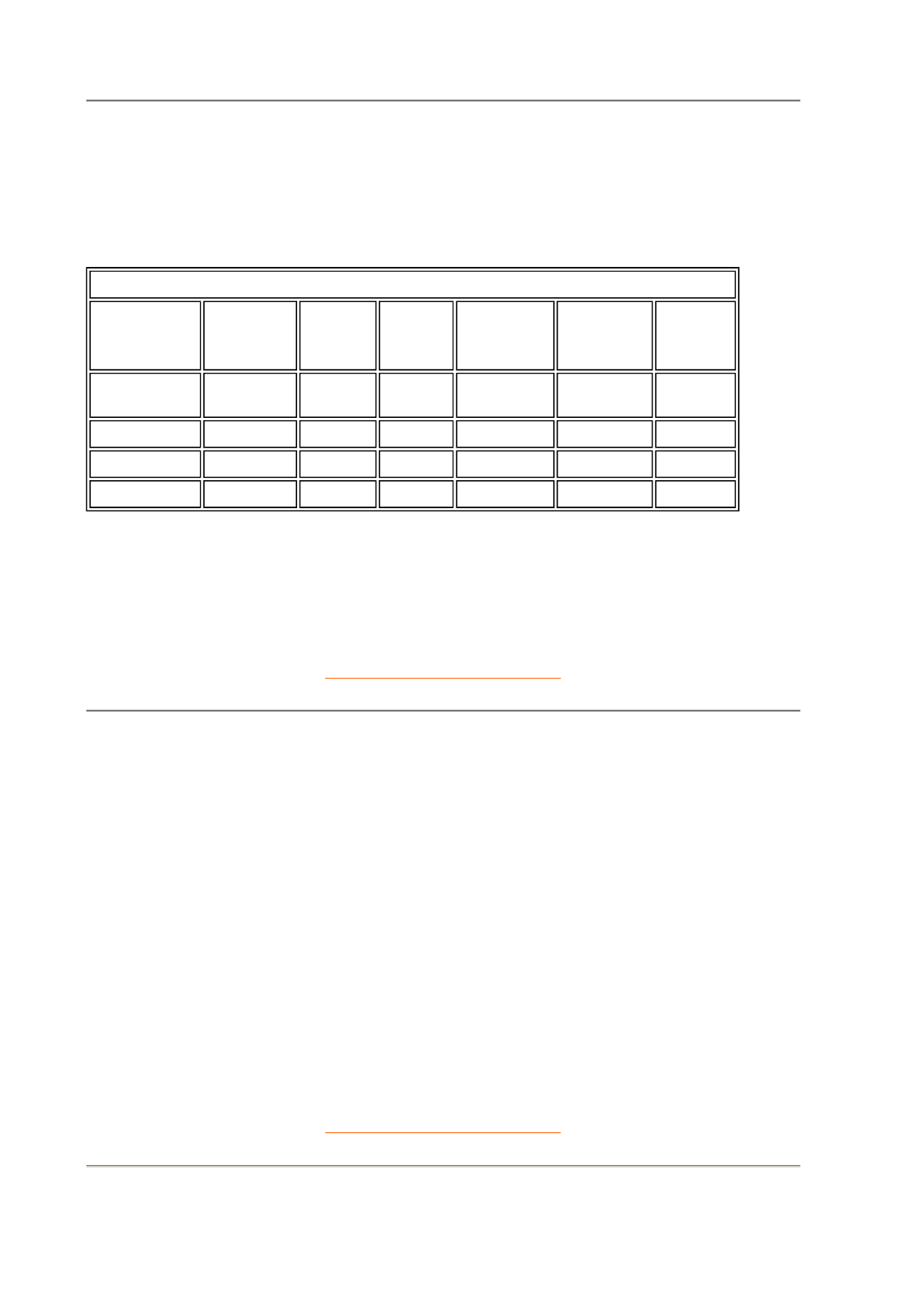
Automatic Power Saving
If you have VESA's DPMS compliance display card or software installed in your PC, the monitor can
automatically reduce its power consumption when not in use. And if an input from a keyboard, mouse or
other input device is detected, the monitor will automatically "wake up". The following table shows the
power consumption and signaling of this automatic power saving features:
RETURN TO TOP OF THE PAGE
Physical Specifications
* These information are subject to change without notice.
RETURN TO TOP OF THE PAGE
Pin Assignment
Power Management Definition
VESA's
Mode Video H-sync V-sync Power
Used
Power
Saving
(%)
LED
color
ON Active Yes Yes Typical 83
W 0 % Green
Stand-by Blanked No Yes < 2W 97% Yellow
Suspend Blanked Yes No < 2W 97% Yellow
OFF Blanked No No < 2W 97% Yellow
This monitor is ENERGY STAR® compliant. As an ENERGY STAR® Partner, PHILIPS
has determined that this product meets the ENERGY STAR® guidelines for energy
efficiency.
• Dimensions 17.3" x 17.5" x 17.6" / 440 x 446 x 449mm (including base)
17.3" x 16.1" x 17.6" / 440 x 410 x 449 mm (excluding base)
• Weight 21.3 kg
• Power supply 90 - 264 VAC, 50/60Hz
• Temperature
(operating) 0° to 40°C / 32° to 104°F
• Temperature (storage) -25° to +65°C / -13° to +149°F
• Relative humidity 5% to 95%
* Resolution 1280 x 1024, standard size, contrast max., brightness 50%, 9300°, full white pattern.
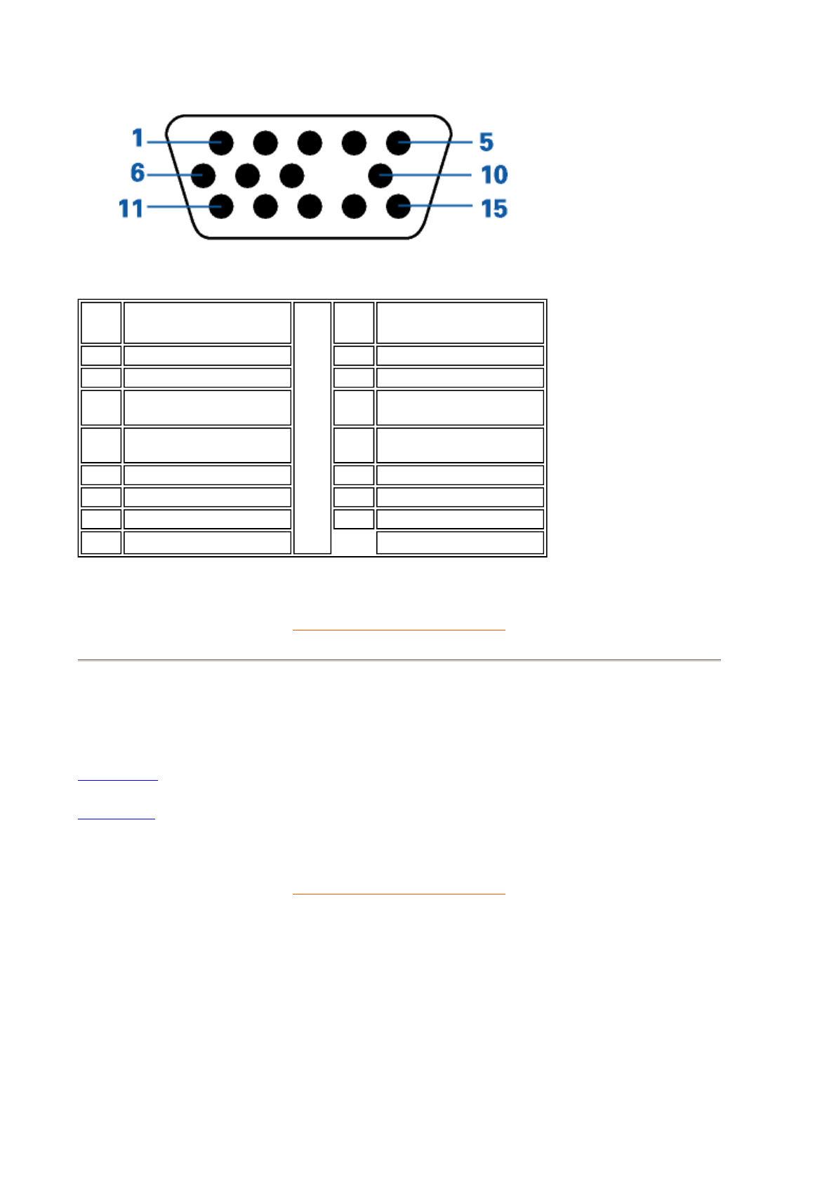
The 15-pin D-sub connector (male) of the signal cable (IBM systems):
RETURN TO TOP OF THE PAGE
Views
Follow the links to see various views of the monitor and its components.
Front View
Rear View
RETURN TO TOP OF THE PAGE
Pin
No. Assignment
Pin
No. Assignment
1 Red video input 9No pin
2 Green video input 10 Logic ground
3 Blue video input 11 Identical output -
connected to pin 10
4 Identical output -
connected to pin 10 12 Serial data line (SDA)
5 Ground 13 H. Sync / H+V
6 Red video ground 14 V. Sync (VCLK for DDC)
7 Green video ground 15 Data clock line (SCL)
8 Blue video ground
Installing your Monitor
Front View • Rear View • 6G3B11 Multimedia Base (option) • PCUH411 USB
Hub (option)
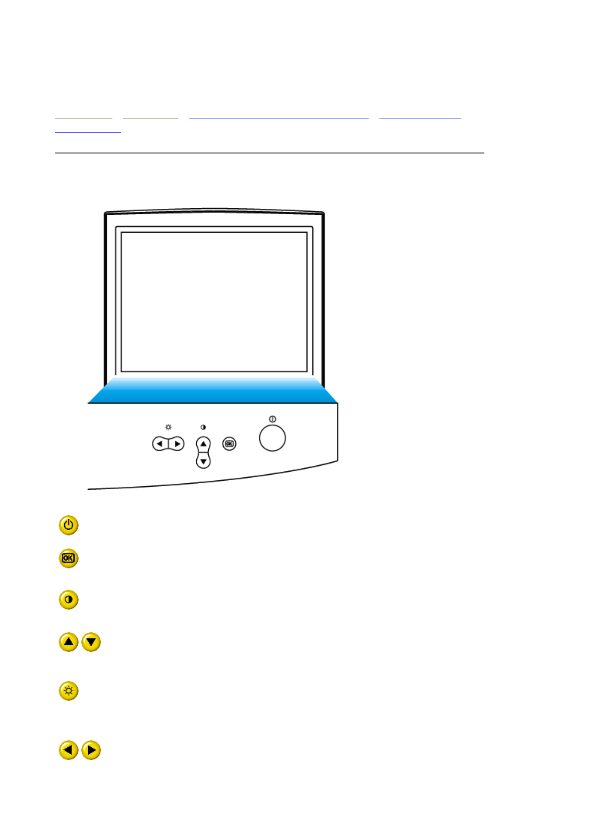
Front View
Power button switches your monitor on.
OK button which when pressed will take you to the OSD controls
Contrast hotkey. When the UP arrow is pressed, the adjustment
controls for the CONTRAST will show up.
UP and DOWN buttons are used when adjusting the OSD of your
monitor
Brightness hotkey. When the RIGHT arrow is pressed, the
adjustment controls for BRIGHTNESS will show up.
LEFT and RIGHT buttons, like the UP and DOWN buttons, are
also used in adjusting the OSD of your monitor.
RETURN TO TOP OF THE PAGE
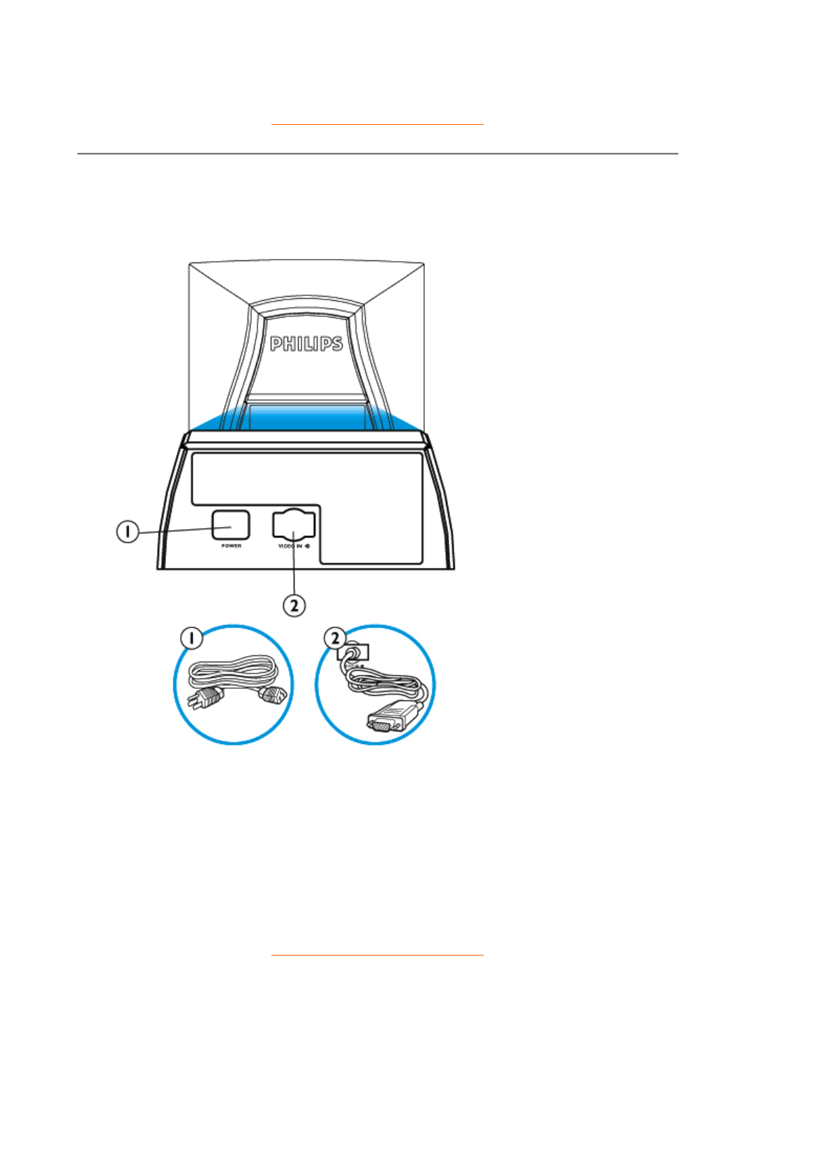
Rear View
1. Power in - attach power cable here.
2. Video In - this is a cable which is already attached to your monitor. Connect
the other end of the cable to your PC.
RETURN TO TOP OF THE PAGE
Regulatory Information
TCO '99 Information • TCO Environmental Requirements • CE Declaration of
Conformity • Energy Star Declaration • Federal Communications Commission
(FCC) Notice (U.S. Only) • Commission Federale de la Communication (FCC
Declaration) • EN 55022 Compliance (Czech Republic Only) • VCCI Class 2
Notice (Japan Only) • MIC Notice (South Korea Only) • Polish Center for Testing
and Certification Notice • North Europe Information • BSMI Notice (Taiwan Only) •
Ergonomie Hinweis (nur Deutschland) • Philips End-of-Life Disposal • Information
for UK only
Safety Precautions and Maintenance • Troubleshooting • Other Related
Information
TCO '99 Information (for 109B40 only)
• TCO '99 : Available on 105S, 105B, 107E, 107T, 107B, 107P, 109S, 109B.
Why do we have environmentally labeled computers?
In many countries, environmental labeling has become an established method for encouraging the
adaptation of goods and services to the environment. The main problem, as far as computers and
other electronics equipment are concerned, is that environmentally harmful substances are used
both in the products and during their manufacture. Since it is not so far possible to satisfactorily
recycle the majority of electronics equipment, most of these potentially damaging substances
sooner or later enter nature.
There are also other characteristics of a computer, such as energy consumption levels, that are
important from the viewpoints of both the work (internal) and natural (external) environments.
Since all methods of electricity generation have a negative effect on the environment (e.g. acidic
and climate-influencing emissions, radioactive waste), it is vital to save energy. Electronics
equipment in offices is often left running continuously and thereby consumes a lot of energy.
What does labeling involve?
This product meets the requirements for the TCO'99 scheme which provides for international and
environmental labeling of personal computers. The labeling scheme was developed as a joint
effort by the TCO (The Swedish Confederation of Professional Employees), Svenska
Naturskyddsforeningen (The Swedish Society for Nature Conservation) and Statens
Energimyndighet (The Swedish National Energy Administration).
Approval requirements cover a wide range of issues: environment, ergonomics, usability,
emission of electric and magnetic fields, energy consumption and electrical and fire safety.
The environmental demands impose restrictions on the presence and use of heavy metals,
Congratulations! You have just purchased a TCO '99
approved and labeled product! Your choice has provided you
with a product developed for professional use. Your
purchase has also contributed to reducing the burden on the
environment and also to the further development of
environmentally adapted electronics products.
Energy Star Declaration
PHILIPS
109B4*
RETURN TO TOP OF THE PAGE
Federal Communications Commission (FCC) Notice (U.S. Only)
Reorient or relocate the receiving antenna.
Increase the separation between the equipment and receiver.
Connect the equipment into an outlet on a circuit different from that to which the receiver is
connected.
Consult the dealer or an experienced radio/TV technician for help.
This monitor is equipped with a function for saving energy which supports the VESA Display
Power Management Signaling (DPMS) standard. This means that the monitor must be
connected to a computer which supports VESA DPMS to fulfill the requirements in the
NUTEK specification 803299/94. Time settings are adjusted from the system unit by
software. From indicated inactivity to Power Saving Position A2, the total time must not be set
to more than 70 minutes.
NUTEK VESA State LED Indicator Power Consumption
Normal operation ON Green < 100 W
Power Saving
Position A1
Suspend Yellow < 2 W
Power Saving
Position A2
OFF Yellow < 2 W
As an ENERGY STAR® Partner, PHILIPS has determined that this
product meets the ENERGY STAR® guidelines for energy efficiency.
We recommend you switch off the monitor when it is not in use for quite a long
time.
This equipment has been tested and found to comply with the limits for a Class B
digital device, pursuant to Part 15 of the FCC Rules. These limits are designed to
provide reasonable protection against harmful interference in a residential
installation. This equipment generates, uses and can radiate radio frequency
energy and, if not installed and used in accordance with the instructions, may
cause harmful interference to radio communications. However, there is no
guarantee that interference will not occur in a particular installation. If this
equipment does cause harmful interference to radio or television reception, which
can be determined by turning the equipment off and on, the user is encouraged to
try to correct the interference by one or more of the following measures:
Use only RF shielded cable that was supplied with the monitor when connecting this monitor to a
computer device.
To prevent damage which may result in fire or shock hazard, do not expose this appliance to rain
or excessive moisture.
THIS CLASS B DIGITAL APPARATUS MEETS ALL REQUIREMENTS OF THE CANADIAN
INTERFERENCE-CAUSING EQUIPMENT REGULATIONS.
RETURN TO TOP OF THE PAGE
Commission Federale de la Communication (FCC Declaration)
Réorienter ou déplacer l'antenne de réception.
Augmenter la distance entre l'équipement et le récepteur.
Brancher l'équipement sur un autre circuit que celui utilisé par le récepteur.
Demander l'aide du marchand ou d'un technicien chevronné en radio/télévision.
N'utiliser que des câbles RF armés pour les connections avec des ordinateurs ou périphériques.
CET APPAREIL NUMERIQUE DE LA CLASSE B RESPECTE TOUTES LES EXIGENCES DU
REGLEMENT SUR LE MATERIEL BROUILLEUR DU CANADA.
RETURN TO TOP OF THE PAGE
EN 55022 Compliance (Czech Republic Only)
Changes or modifications not expressly approved by the party responsible for
compliance could void the user's authority to operate the equipment.
Cet équipement a été testé et déclaré conforme auxlimites des appareils
numériques de class B,aux termes de l'article 15 Des règles de la FCC. Ces
limites sont conçues de façon à fourir une protection raisonnable contre les
interférences nuisibles dans le cadre d'une installation résidentielle. CET appareil
produit, utilise et peut émettre des hyperfréquences qui, si l'appareil n'est pas
installé et utilisé selon les consignes données, peuvent causer des interférences
nuisibles aux communications radio. Cependant, rien ne peut garantir l'absence
d'interférences dans le cadre d'une installation particulière. Si cet appareil est la
cause d'interférences nuisibles pour la réception des signaux de radio ou de
télévision, ce qui peut être décelé en fermant l'équipement, puis en le remettant
en fonction, l'utilisateur pourrait essayer de corriger la situation en prenant les
mesures suivantes:
Toutes modifications n'ayant pas reçu l'approbation des services compétents en
matière de conformité est susceptible d'interdire à l'utilisateur l'usage du présent
équipement.

1
Exhibit 4
The brief ckt. description of M40
109B4/109S4/107P4” Monitor
0. Functional Block Diagram
1. General Description
2. Description of Circuit Diagram
A. Power Supply
B. Horizontal Deflection/Vertical Deflection/EHT Generator
C. Video board
D. H / V convergence control
E. Micro-controller & DDC 2B
2
1. GENERAL DESCRIPTION
The M40 platform includes 109B4 using 19” flat shadow mask CRT, 109S4 using 19”convention CRT
and 107P4 using 17” flat CRT, they are so-called “Digital Controlled Auto-scan Color Display Monitor”
with high resolution which can operate at horizontal scan frequency from 30kHz up to 97KHz, 92KHz
and 92KHz for109B4, 109S4 and 107P4 respectively, and vertical scan frequencies can operate from 50
to 160 Hz.
These monitors are equipped with an embedded micro-controller, which can preset the required modes,
the M40 also provides many functions, such as digital adjustable picture, DDC2B, sRGB, LF3, low
emission TCO99, high immunity, ---- etc.
These monitors comply with TCO99 low emission standard and also fulfill E2000 automatic power
saving requirements; to reduce power consumption less than 2 watts in power saving OFF mode, the
monitor also can complies with VESA standard and energy star computer program initiated by the EPA.
2. DESCRIPTION OF CIRCUIT DIAGRAM
This description mainly introduces the functions including power supply, horizontal / vertical deflection,
video amplifier, micro-controller and H / V convergence control, etc.
A. POWER SUPPLY
The monitor is designed to adopt switching mode power supply which can operate mains input from
90VAC to 264VAC, this switching power supply apply an IC TEA1507 for SOPS controller. The
control scheme transforms a switching converter from a voltage source into a multi-output voltage, the
control concept is exhibited many desirable properties such as inherent over-load protection, stable and
fast system response, the maximum output power capability is up to 110 watts for different models, then
a power limiting circuit is added for different power delivery and safety reason, on main power supply
circuit, secondary feedback via a photo-coupler is used to obtain a stable output voltage, the secondary
outputs supply all necessary voltages for deflection and video and micro-controller.
In order to meet new requirement of E2000 - power consumption less 2 watts @ off mode, The
TEA1507 power supply is adopt, the power applies SOPS technology, not only supply the +5V to
micro-controller & rest, and to be switched into burst mode via micro-controller for less 2 watts
requirement @ off mode (actual measuring data is typical 1 watt)
This monitor can save power consumption while no sync pulses and automatically recover to
normal power on when sync signals are detected by micro-controller, the power saving off mode still
exist in new designed monitors but suspend / stand-by mode are deleted due to pattern infringement
issue, but still reserve them for the option and future implementation required.
B. HORIZONTAL DEFLECTION / VERTICAL DEFLECTION / EHT GENERATOR
HORIZONTAL DEFLECTION:
The heart of horizontal/vertical deflection controller is TDA4841, which can offer a complete and
efficient small signal sync processing for auto-sync monitors, all functions are controlled via I2C bus.
3
This controller provides sync processing, which can accept separate input signals, a very short settling
time after mode change for protection of external power components has been taken into account.
The TDA4841 provides extensive functions like a flexible B+ controller block of H-deflection and a
geometry control with facilities, leading to excellent picture quality, this device also can directly drive the
vertical deflection output stage, the line driver stage, the E/W output stage and all controls are tracked
with the incoming frequencies, picture can be adjusted along horizontal direction by OSD H-shift control,
the horizontal size, east/west, trapezoid corrections are obtained by varying the supply voltage of H-
deflection circuit via buck converter, five capacitors plus power MOSFET switches and DC controlled
linearity coil are designed for optimal screen linearity.
VERTICAL DEFLECTION:
The majority of vertical deflection function is integrated by two ICs: TDA4841 and TDA8172.
The TDA4841 takes care of sync polarity correction, automatic catching and holding of the vertical
oscillator, generation of saw-tooth drive current for vertical output and vertical s-correction, and
generation of a correct V-blanking pulse for video blanking during vertical retrace lines.
The TDA8172 is a DC-coupled vertical deflection booster with differential input signals is suitable for
color monitor. The output stage has thermal and soar protection, and high linear saw-tooth signal
amplification to obtain the required vertical deflection current.
EHT GENERATOR
The IC UC3843AN is used as a controller to generate required extra high voltage for CRT, the
transformer(LOT) transfers the voltage to required anode voltage and rest tertiary output voltage.
The adjustable focus (G3) and screen (G2) voltages are internally derived from the anode voltage, other
secondary windings are used to generate the voltages for G1, also provides dynamic focus on G4 to get a
good focus performance. (G4 is also adjustable).
For safety reasons, x-ray protection circuit is included, that UC3843AN will feed fold the EHT generator
if the anode voltage exceeds a certain value (27—29.5kV), this circuit is also used for over beam current
protection, it will feed fold the EHT in case the total beam current can not exceeds a certain value.
C. VIDEO AMPLIFIER
VIDEO AMPLIFIER:
The video circuit mainly consists of Light Frame IC TDA4823, pre-amplifier TDA4886A, post amplifier
LM2435T and DC restoration circuit and OSD IC Novatek 68275-00031 the video DC level and gain at
cathode are controlled via I2C bus & software.
The red, green and blue video signals are amplified by pre-amplifier and post-amplifier, then AC couple
to CRT cathodes via DC restoration circuits, three cut-off adjustments are provided to set the video black
level at cathode for all three guns, three individual gain adjustments are also provided to adjust the white
balance, both cut-off and gain controls are digital control via micro-controller.
A spot-killer circuit is also added to prevent the CRT damage due to spot burn out when the set is
switched off.
D. H / V CONVERGENCE CONTROL (only for 107P4)
4
The convergence coils are combined with deflection yoke, they are also driven by DC amplifiers.
Via OSD menu, two control functions H-convergence and V-convergence can be selected to adjust
the convergence of CRT by using digital control.
E. MICRO-CONTROLLER & DDC2B
GENERAL DESCRIPTION:
The Weltrend WT62P2 micro-controller is used to control all required functions of monitors, the
preset data are stored in EEPROM M24C16, the most important point is used “ interrupt “ to do
the fast detect of mode change, then the MCU deliver a good protection behavior for horizontal
output transistor during mode change. Meanwhile, the DDC2B function is by software control.
HARDWARE DEFINITION:
a) KEY BOARD
There are five keypads at the front of monitor for the OSD control.
- OSD function key:
- Enter
Push it, to confirm the entrance or exit from the OSD window
- UP
To select the parameters which are chosen from OSD.
- DOWN
To select the parameters which are chosen from OSD.
- RIGHT
To adjust the parameter which are chosen from OSD to right side
- LEFT
To adjust the parameter which are chosen from OSD to left side
b) OSD will disappear and SAVE AUTOMATICALLY after non-operation.
c) Software will control the DPMS according to the SYNC status.