Philips Lighting North America LRD1730 OccuSwitch Wireless Dimmer User Manual
Philips Lighting North America Corporation OccuSwitch Wireless Dimmer
User Manual

PHILIPS
PHILIPS
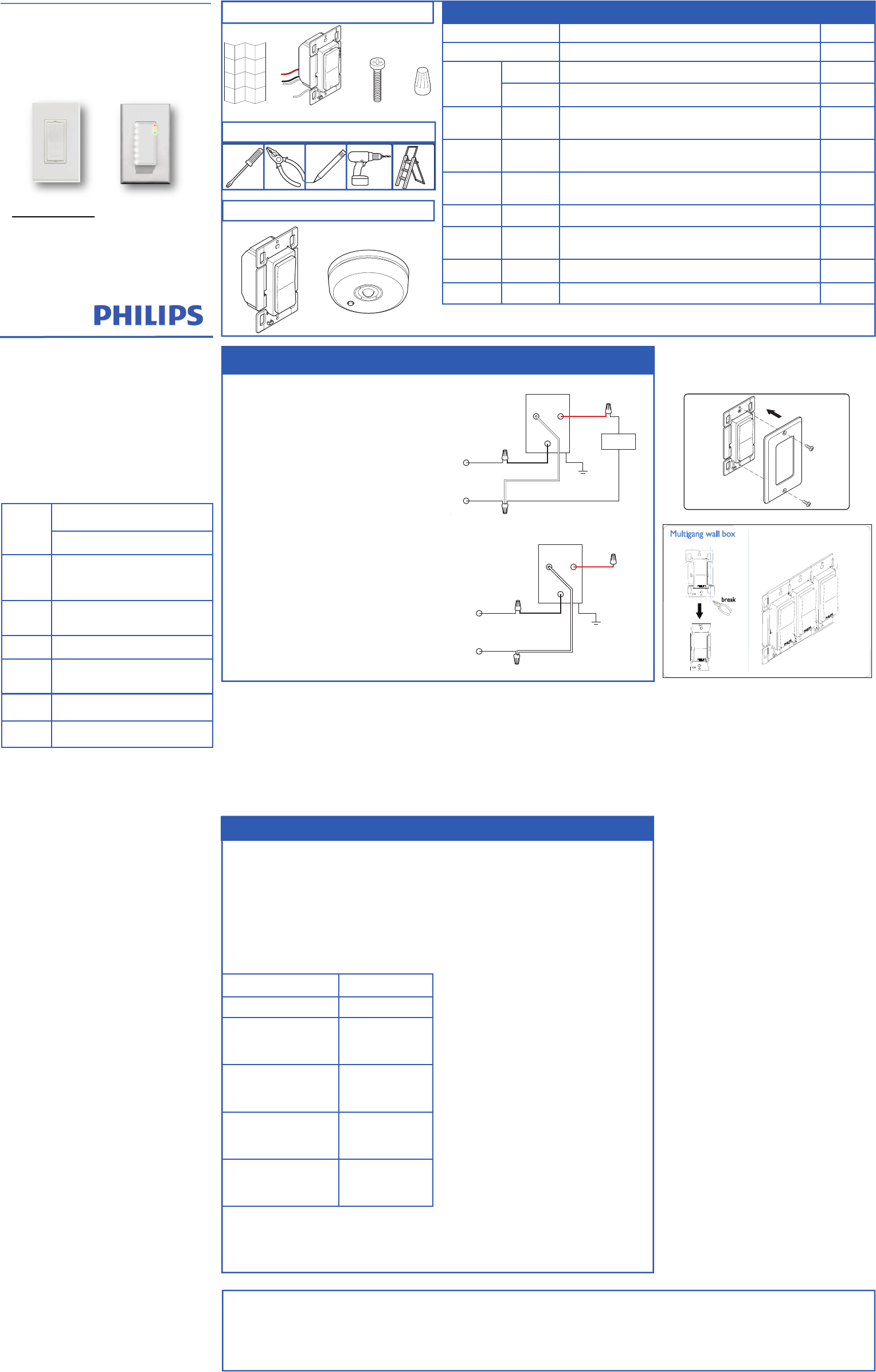
black brass
ground
white
red
load
120-277 V~
50 / 60 Hz
hot/live
neutral
black brass
ground
white
red
hot/live
neutral
120-277 V~
50 / 60 Hz
y
(4x)(1x)(1x)
PHILIPS
(2x)
PHILIPS
Installation Guide
OccuSwitch Wireless System
LRM172100 Switch
LRM173000 Dimmer
WARNING:WiringthewalldevicewithpowerONis
unsafeandcouldresultinseriousinjuryordeath.Turn
Offpoweratthecircuitbreakerbeforeinstallingthe
SwitchesandDimmers.
1SwitchOfflinevoltageatcircuitbreaker.Wiring
HOTmaydamagetheelectronicandvoidthewar‐
ranty.
2RemovetheoldSwitchandinstallnewOccuSwitch
DimmerorSwitchfollowingthewiringdiagram.
Note:doNOTswapHot/liveandneutral.
3Wirelessremote(3‐way)deviceswireasfollows:
Themasterdimmer(thatcontrolstheload)accord‐
ingtotheregularwiringdiagram.
Wiretheremoteswitch/dimmer(noload)accord‐
ingtothewiringdiagram.
Remote(3‐waygrouping)configurationisamenu
option,seeConfigurationinstruction(Yellow#2)on
backpage.
4Toinstallinmulti‐gangwallback‐box,breakthe
tabsofjoiningsides.Donotbreaktheoutsidetabs
ondevicesattheendofthegang.Upto3devices
canbegangedinonethree‐gangbox.
5Placethedimmerintothewallback‐box,andse‐
curewiththemountingscrews.
6Powerthecircuitatfuseorcircuitbreaker.
7CheckoperationON/OFForFadeUp/DimDown.
InstallationSteps
1.Installwalldevice
2.Installsensor(separateinstructions)
3.Linkdevices
4.Configure,testandfinish
ProductDescription
OccuSwitch™Wirelessautomaticallycontrolsthelights
basedonoccupancyanddaylight.Thesystemhastwo
parts:ceiling‐mountedsensorandwallmountpower
handlingdevice(switchordimmer).Theswitchwillturn
thelightsOnandOffbasedontheinformationreceived
fromthewirelessoccupancysensor.Thedimmerwill
dimlightsUpandDowntotheappropriateintensity
baseontheavailabledaylightinthespace.Thedimmer
canalsomanuallydimthelights.
Keyfigures
SAFETY
Partsoftheswitch&dimmercarrylinepower,whichisapoten‐
tiallethalvoltage.Thisproductwasdesignedandmanufactured
toensuremaximumsafetyduringoperationandservice.Always
readthesesafetyinstructionsbeforeinstalling,maintainingor
servicingtheproduct,andstrictlycomplywiththeseinstruc‐
tions.
General
‐Ifyouareunsureaboutanypartoftheseinstallationinstruc‐
tions,consultaqualifiedelectrician.
‐Thedevicesaredesignedforindooruseonly.
‐Toavoidshortcircuits,donotexposethisproducttorainor
condensingmoisture.Shortcircuitmaycausefireorelectric
shockhazard.Operatethedevicesbetween41°Fand104°F
(5°Cand40°C)ambienttemperature..
‐Useonlyasoftdampclothtoclean,neveruseanyabrasiveor
chemicalcleaner.
‐Wheneveritissuspectedthatanunsafeconditionexists,
switchoffpoweratthecircuitbreakerandreplacethedevice.
Safetyislikelytobeimpairedif,forexample,theequipment
failstoperformtheintendedfunctionsoriftheequipment
showsvisibledamage.Donotpaintthedevices.
WallDevice(Switch&Dimmer)only
‐Disconnectpoweratcircuitbreakerorfusewhenservicing,
installingorremovingthefixtureoftheswitch.
‐Onlyusewithcopperorcoppercladwire.
‐Wireswitchtothelinepoweraccordingtothewiringscheme
inthismanual.
Sensoronly
‐Thesensorcannotcontrolloadsdirectlyusecompatibleswitch
ordimmer.
‐Useonlyhigh‐quality,AAsize,3.6Vlithium‐thionylchloride
batterieswiththesensor.Usingimproperlyratedbatteries
maydamagethesensororfailtooperateproperly.
‐Disposeofusedbatteriespromptly.Keepbatteriesawayfrom
children,donotdisassembleanddonotdisposeofinfire.
WARNING:Theproductisintendedtocontrollighting
loadsonly.DoNOTusetocontrolequipmentthatcouldcreate
hazardoussituations,likeentrapment.Forexamples,doNOT
installthisproducttocontrolmotorizedgates,garagedoors,
industrialdoors,microwaveovens,heatingdevices,etc.
WARNING:Itistheinstaller’sresponsibilitytoensurethat
theequipmentbeingcontrolledisvisiblefromeverycontrol
locationandthatonlysuitableequipmentisconnectedtothese
controls.Failuretodosocouldresultinseriousinjuryordeath.
CAUTION:Thebatteryusedwiththesensordevicemay
presentariskoffireorchemicalburnifmistreated.Donot
recharge,disassemble,heatabove100°C,orincinerate.Replace
batterywithLithium‐thionylchloride(AA3.6V)only.
Useofanotherbatterymaypresentariskoffireorexplosion.
800VA@120VAC(Mark10orequal)
1600VA@277VAC(Mark10orequal)
800W@120VAC(Incandescent)
Notrecommendedbutitworks
Dimmer
NOT
ratedfor:
ElectroMagneticFluorescent
MotorLoads
Switch
Load
Rating
1300VA@120or277VAC
0.25HP@120Vac
Switchoutputonly
Network
Size16Sensors,Switches&Dimmers.
Wireless
Range
Walldevicetosensor:50ft(17m)
Walldevices(sameplane)18ft(6m)
Walldevices(lineofsight)50ft(17m)
Dimen‐
sions‐
4.13”x2.56”inx1.79”(105x65x
45mm)Singlegangwallmount.2.5”d
Dimmer
Load
Ratings
Environ‐
mental
Temp:40°Fto104°F(5°Cto40°C)
Humidity:20%to85%,noncondensing
WallDeviceboxcontents
IndicationMeaningDevice
Red,Yellow,GreenDevicestartsuporresettofactorydefaultsAll
Green
10sec.AdeviceaskedtoshowalllinkeddevicesAll
1Min.DeviceisinlinkingmodeSwitch
Dimmer
Yellow
BlinkIrregularSensorisshowingcoverageSensor
Yellow
Blink
Every2
Sec.DeviceisintheconfigurationmenuSwitch
Dimmer
RedBlinkRegularAlinkeddeviceismissing
(seeTroubleshooting)
Switch
Dimmer
RedBlink2Sec.rateDeviceisintheActionmenu All
Steady
YellowAlwaysONLightsareswitchedmanually.Automaticmodereturnsafter
vacancytimeout.
Switch
Dimmer
RedBlink5SecRateSensorBatteryLowSwitch
Dimmer
RedBlink2Sec.RateDuringlinktest=lowbatterySensor
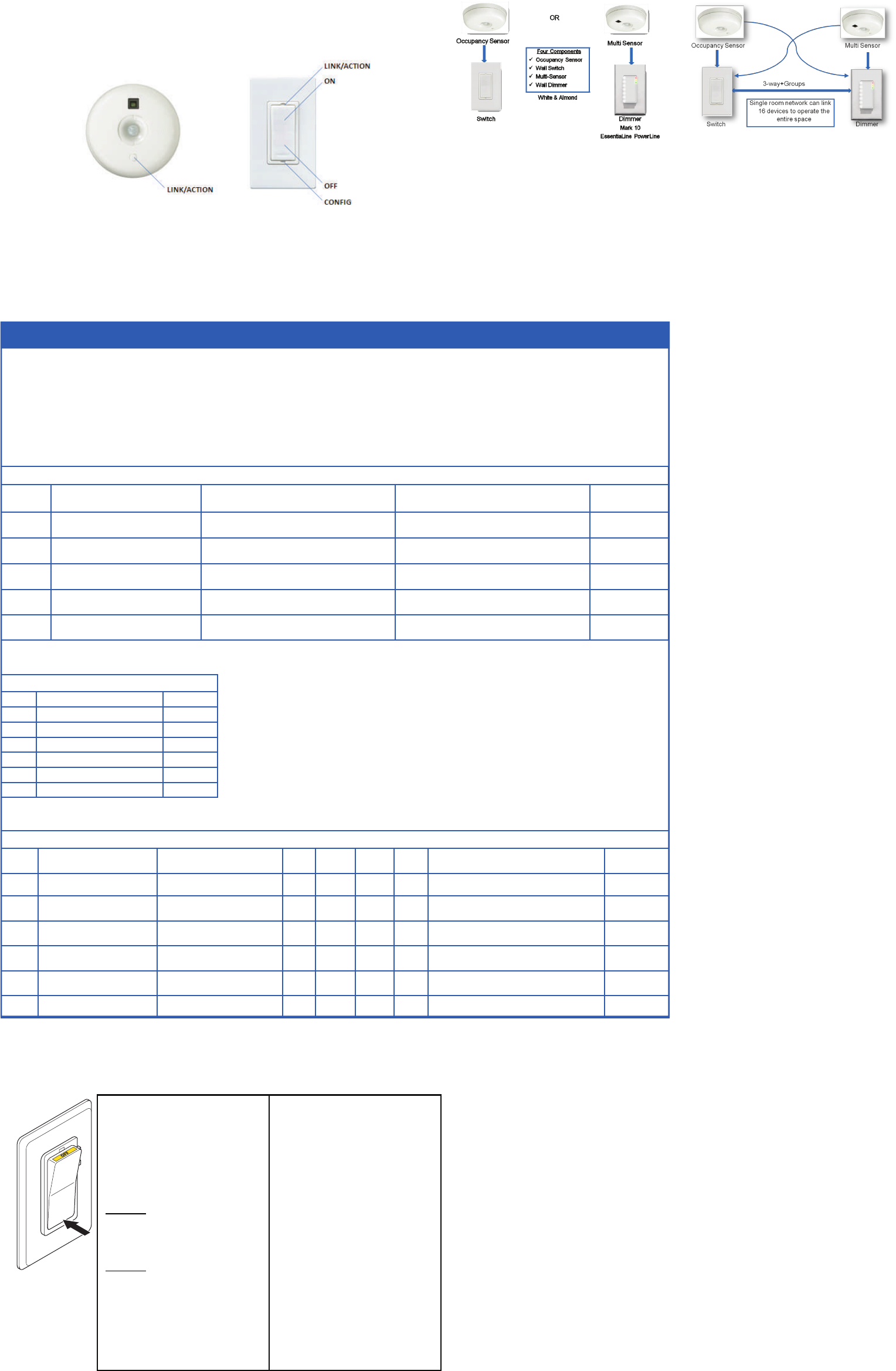
LEDandButtons
1 INSTALLWALLDEVICE
Note:Afterwalldeviceisinstalledandpowerisre‐
turned,testallwalldevicesbypressingtherocker
switchON/OFF.Allswitches/dimmersshouldcontrol
connectedloads.Iftheydonotcontrolthelights
checkwiring.
Createanetwork:Tocreateawirelessnet‐
workbycombinationofupto16switches,dimmers
andsensorstakethefollowingsteps.
HINT:topreventcross‐linkingroomsonlyoneperson
shoulddothelinks.
3LINKDEVICES
Troubleshooting
SeeLEDsandbuttonsdescription.
Whenlinking,ifRedLEDonthesensorturnsOn,
thenlinkingfailed.Tryagainandmovethesensor
closertotheswitch,(within50ft.)
Whenlinking,ifRedLEDonthesensorstartsto
blink,youpressedandheldtheLINKbuttontoo
long.ThesensorenteredtheACTIONmenu.Press
andholdthelinkbuttontoexit.
Warning:IfthegreenLEDstartsblinkingonanother
switch/dimmer,thatswitch/dimmerisnowalsoin
linkingmode,startingitsownnetwork.Pressthe
LINKbuttononthatswitch/dimmerandtrythe
wholeprocedureagain.Iftheproblempersists,the
distancebetweenthenewswitch/dimmerandthe
existingswitchmaybetoolarge(seeKeyfigures).
Note:IftheyellowLEDisturnedONafterlinking,the
switch/dimmerisinmanualoverride.Afterthesensor
timerhasexpired,itwillreturntoautomaticmodeand
theLEDwillgooff.Or,holddowntheONrockeruntil
theyellowLEDgoesout,returningtoautomode.
RESETtofactorydefaultsettings‐Ifthelinksorset‐up
isnotcorrecttheycanbeclearedineachdeviceby
holdingdowntheLINK/ACTIONButtonforabout10
seconds.ReleasewhenLED’sbrieflyblinkalltogether.
AfterreleasingtheystepRED‐YELLOW‐GREEN.
ACTIONRESULTS
TestOn/OffandsettoOffLightsturnoff.
1.BrieflypresstheLINK
button(Topofswitch/
dimmer)forlinkingmode.
GreenLEDonthe
switch/dimmerstarts
blinking.
2.BrieflypresstheLINK
buttononthesensortoadd
ittothenetwork.
LightsturnOnand
sensor’sgreenLED
turnson.
3.BrieflypresstheLINK
buttononadditionaldevices
toaddtonetwork.
GreenLEDoneach
deviceturnsOnto
confirmlink.
4.BrieflypresstheLINK
buttononfirstswitch/
dimmeragaintoexit.
GreenLEDonthe
switch/dimmerstops
blinking.
FCCCOMPLIANCESTATEMENT
Thisdevicecomplieswithpart15oftheFCCrules.Operationissubject
tothefollowingtwoconditions:(1)Thisdevicemaynotcauseharmful
interference,and(2)thisdevicemustacceptanyinterferencereceived,
includinginterferencethatmaycauseundesiredoperation.Anychanges
ormodificationsnotexpresslyapprovedbyPhilipscouldvoidtheuser’s
authoritytooperatethisequipment.Thisproductisintendedforcom‐
mercialuseonly.
CopyrightNOTICE
Allreferencedbrands,productnames,service
namesandtrademarksarethepropertyoftheir
respectiveowners.
Copyright2011KoninklijkePhilipsElectronicsN.V.
TECHNICALSUPPORT
Fortechnicalsupportonthisproductcontact:
PhilipsLightingElectronicsN.A.
10275W.HigginsRoad
RosemontIL60018
CustomerCare:1‐800‐372‐3331
tech.service.rosemont@philips.com
Mountingdetails
NeutralRequired
Bothwalldevice(switch&Dimmer)requireaneutral.
Theneutralcircuitdesignprovidesamorestableand
predictableelectricalsource.Themostcommonno‐
neutraldesigntricklesthereturnpowerthatoperates
communicationcircuitsinthewalldevicebackthrough
thelightingload(ballast).Thismethodhastoomany
uncertaintiestobe100%reliable.Aswemovefor‐
wardwiththisproductnewtechnologiesmayallowus
tochangetheneutralrequirement.
Switch&DimmerWiringDiagram
RemoteDeviceWiringDiagram
WallDevices&CeilingSensor
Toolsrequired(forentireinstall)

SET‐UPOPTIONS
Forbestresultseteachdesirableoptionintheorder
listedbelow.
PHILIPS
WARRANTYSTATEMENT
ThePhilipsOccuSwitch™Wirelessproducts,whenproperly
installedandundernormalconditionsofuse(withoutover‐
load,abuseoralteration),iswarrantedtoyou,theoriginal
user,foraperiodoftwo(2)yearsfromthedateoforiginal
purchase,tobefreefromdefectsinmaterialsandworkman‐
ship.Ifduringthewarrantyperiodyoubelievethepurchased
productoranypartthereofhassuchadefect,youmustreturn
theproduct(orpart)atyourcostduringsuchperiod,with
proofofpurchase(orifinstalledbyathirdpartyawritten
explanationofinstallationtransactionwithproofofdate),to
PhilipsLightingElectronicsN.A(1‐800‐372‐3331/
www.philips.com/advance),forrepairorreplacement(ortoan
authorizedPhilipsLightingElectronicsN.A.supplierwhich
agreesinadvancetohandlethereturnandreplacementby
factoryauthorization).IftheproductorpartisfoundbyPhilips
tohavebeendefectiveinmaterialorworkmanshipitwillbe
repairedorreplaced(asdeemednecessarybyPhilipsLighting
ElectronicsN.A.),andthereplacementwillbereturnedtoyou
freeofcharge.Theoriginaluserissolelyresponsibleforany
costsassociatedwithremovalandre‐installationoftheprod‐
uctandshippingtoPhilipsLightingElectronicsN.A.orits
authorizedsupplier.
TroubleshootingSystem
Thelightsturnofftooquickly:Thesystemhasa
smarttimerthatadjusttheoffdelaytimeautomati‐
cally.Tochange,setsensor’sminimumtimeoutdialto
ahighervalue.
ThesystemissettoManualON,butlightsturnon
automatically:Whenenteringtheareawithin5min‐
utesafterlightsturningoff,thesystemassumesthat
turningoffwasundesiredandturnONthelights.
Thesystemshowsthatalinkeddeviceismissing:
Whenadeviceismissing,usetheACTION#1menuto
showalllinkeddevices.Ifasensordoesnotshowas
linked,itsbatterymayneedtobereplaced.Ifthisdoes
notresolvetheerror,resetalldevicesandlinkthem
again.
ThelightsimmediatelyturnONafterbeingturnedoff
Thesensormaybeplacedtooclosetoa(heatgenerat‐
ing)lightsource.Movethesensortoabetterlocation.
Resetthedevicetofactorydefaults
Toresetthedevicetoitsfactorydefaultconfiguration:
Pressandholdthelinkbuttononthedevicefor
morethan10seconds.Releasethebuttonwhenthe
red,yellowandgreenLEDslightbriefly.
Maintenance
Routinelampreplacement
Tosafelydoaroutinelampreplacement,
onallswitches,firmlypresstheOFF‐side
untiltherockerclicksintotheposition
whereayellowbandwith“OFF”becomes
visible.
Theloadisnowtemporarilyseparated
fromthelinevoltagebyanairgapswitch,
soyoucansafelyreplacethelamp.
WARNING:Iftheairgapfunctionisnot
used,thepowermaybeswitchedON
unintentionallybythesensorwhilereplac‐
ingthelamp.Thiscouldresultinserious
injuryordeath.
WARNING:Foranyprocedureother
thanlampreplacement,powermustbe
disconnectedatthemainelectricpanel.
UseapprovedLOCK‐OUT/TAG‐OUTproce‐
durestoinsurethatthecircuitisnotacti‐
vatedaccidently.WorkingwithpowerON
isunsafeandcanresultinseriousinjuryor
death.
Replacingthesensorbattery
CAUTION:Youmusthavereadthe
SAFETYsectionbeforereplacingthe
battery.
Toreplacethebatteryofthesensor:
1.Rotatethesensorcounterclockwise
toremovefrommountingplate.
2.Inasafeanddryplace,removethe
oldbatteryandinsertthenew
battery.
CAUTION:Useonlyhigh‐qualityAA
size3.6VDClithium‐thionylchlo‐
ridebatterieswiththesensor.
Usingimproperlyratedbatteries
maydamagethesensor.
3.Placethesensorbackonthe
mountingplateandrotateclock‐
wisetofixit.
4.Disposeofusedbatteryproperly.
DONOTthrowintrash.Keepaway
fromchildren.Donotdisassemble
anddonotdisposeofinfire.
4CONFIGURE,TEST&FINISH
Configure
Whenallsensorsandwalldevicesarelinked,youcan
changetheoperationsettings.Thisisdoneatanywall
device;thesettingsareautomaticallysenttotheother
devicesintheroomsnetwork.Youcanselectthefol‐
lowingoptionsintheConfigurationandActionmenus.
(Config#4)
SetHighEndLevel‐Ifyouwanttolimitthemaxi‐
mumoutputfromadimmersetthedesiredhighend
levelandrunthroughConfigurationMenu(Yellow)#4.
Aftersuccessfullyinstallingandlinkingthesensorsand
walldevicesyoucanchangesettingstocustomizethe
systemtotheneedsoftheuser.
Configurationandset‐up
Todimup,pressandholdtheONbutton
Todimdown,pressandholdtheOFFbutton
MenuoperationsuseCONFIGandLINK/ACTIONbut‐
tonsasdescribedintheConfiguration(YELLOW)and
Action/REDmenusbelow.
CONFIGURATION(Yellow)MenuforbothWallDevices‐PressCONFIGbutton(Longtoenter)(Shortfornextitem)
ItemDescriptionAction
Store
Setting
StartYellowSpike(…/…)ExistLongPressCONFIGtoexitN/A
1YellowBlinks(…1…)ManualON/AutoOFF(Title24)LongCONFIG=ManualON
LongACTION=AutoONAutomatic
2YellowBlinks(…1..1…)Multi‐WayConfigurationLongCONFIGtocreatemulti‐waygroupLongCONFIG
3YellowBlinks(…1..1..1…)DimmerResponseCurve
(DimmerOnly)LongCONFIGtochangeresponsecurveLongCONFIG
4YellowBlinks(…1..1..1..1…)SetHighEndLevel(TaskTuning)
(DimmerOnly)
LongCONFIG=Setsmaximumdimlevel
LongACTION=Returnto100%Automatic
Indicator
ACTION(Red)MenuforSensorsandWallDevices‐PressLINK/ACTIONbutton(Longtoenter)(Shortfornextitem)
ItemIndicatorDescription
Wall
Switch
Wall
Dimmer
Multi‐
Sensor
Occ.
SensorActionResults
StartRedSpike(…/…)ExitXXXXLongLINK/ACTIONtoexit
1RedBlinks(…1…)ShowLinkedDeviceXXXXLongLINK/ACTIONtostartAutomatic
2RedBlinks(…1..1…)TestSensorCoverageXXXXLongLINK/ACTIONtoStart
ShortLINK/ACTIONonsensortoFinish
3RedBlinks(…1..1..1…)CalibrateDaylightdimming
set‐point(<1min.process)N/AXXXLongLINK/ACTIONtoStartAutomatic
4RedBlinks(…1..1..1..1…)DaylightHoldBackXN/AXXLongLINK/ACTIONtoStartAutomatic
5RedBlinks(…1..1..1..1..1…)ChannelChangeXXXXLongLINK/ACTIONtoStartAutomatic
SET‐UPhint
Useasmallscrewdriveorsimilardevicetopushthe
Menubuttons.
Shortbuttonpress:<1second
Longbuttonpress:>2seconds
Testsensorcoverage
Oncealldevicesareinstalled,linkedandconfigured,
youcantesttheinstallationtoensurethat:
Thesensordetectsmotionintheworkspace.Testto
makesuresensordoesnotpickupmotionfromadja‐
centareas,e.g.thehallway.Thiscanbedoneatany‐
time,seeACTIONMenuforsteps.
(Config#2)
Multi‐WayConfiguration‐Severalswitchesand
dimmerscanbeputinagroupthatcontroleachoth‐
ersloadwhenoperatedmanually.
Youcancreateseveralindependentcontrolgroups
linkedtotheceilingsensors.
1.UseCONFIGmenuitem2‐Allwalldeviceswill
starttoblink:GREENisincluded,REDisexcluded.
2.TaptheONbuttontoinclude,OFFbottom,to
exclude.
3.LongCONFIGbuttonpresswillsavethesettings.
4.Repeatfromstep1ondifferentwalldevicesto
formmoregroups.
(Config#3)
DimmerResponseCurve‐If
theDaylightdimmingresponse
istooaggressivetheDimmer
canbesettorespondlessto
daylight.Iftheresponseistoo
lowthedimmercanbesetto
reactmoretoadditionalday‐
light.
DimmerResponseCurve
1Blink‐TopLED‐50%
2Blink‐2ndLED‐20%
3Blink‐3rdLED‐10%
4Blink‐4thLED(default)StraightLine
5Blink‐5thLED+10%
6Blink‐6thLED+20%
7Blink‐BottomLED+50%
(Action#3)
DaylightCalibration(FIRSTTIME)‐Onlyone
sensorcanbelinkedtooneSwitch(Hold‐back)orone
Dimmer(continuousdimming)forDaylightRegulation.
ThefirsttimethedaylightActionMenuisactivatethe
systemunlocksandlinksthesenortothewalldevice
forDaylightregulation.Thiscanbedonefromthefloor
beforemountingthesensor.
Nexttime‐Afterthefirstactivationandcalibration
thedaylightmenucanberunfromthewalldeviceto
recalibratethedaylightsettings.
Calibrationprocess‐Whenthesensorandthewall
deviceentercalibrationmodethe
Tip:Itisimportantthatthedaylightisconstantandis
nottoobright(noneedtocalibrateinthedark).
1.Usedimmertodimtotherequiredlightlevel
usinglightmeterontheworksurface.
2.Gointoactionmenuonthesensortoselect
Calibrationdaylightregulationset‐pointmenu
item.(YellowLEDstartsBlinking)
3.Cleartheareaunderthelightsensor(walkaway).
4.AutomaticConfigurationwillstartinabouta
minute.Alldimmersinthesystemgoto100%,
thenswitchoff.ThegreenLEDonthedevice
turnson.Sensorconfirmsnewsetpointusing
greenLED.Thesystementersautomaticlight
regulationmode.
Note:Thisprocesscanberepeatedanytimeafterthe
firsttimefromthewalldevicewithouttouchingthe
(Config#1)
ManualON/AUTOOFF(Title24mode)‐Thisis
apopularsettingformaximumenergysavings.Itforce
theoccupanttomanualactivatethelightswhenthey
enterthespaceandautomaticallyturnOFFthelight
whentheyleave.Thissaveenergybykeepthelights
OFFuntiltheyareactuallyneeded.
Finish
OccuSwitchSensorsandWallDevicesdonotneedany
regularmaintenance.Youmayfindaspeoplechange
spaceandfutureisre‐arrangedthatyouneedtore‐
calibratethedaylightfunctions.Thiscaneasilybe
doneatfloorlevelfromthewalldevice.
(Action#5)
ChannelChanging‐Insomebuildingenvironments
theradiosignalusedforOccuSwitchWirelessmay
encounterinterferencefromanotherradiodevice.
Channelchangingactivatethesystemautomaticradio
analysisfunctiontoeresetthechannel.Usethisfunc‐
tionifyouarehavingcommunicationsissues.
ManualMode‐Manualmodeisenteredwhenthe
rockswitchispressedandtheYellowLEDcomesOn.
Aftersensorsarelinked,thesystemwillreturntoauto
modewhentheroomifvacantandthedelaytimer
expire.ToreturntoAutoModeHolddowntheOn
rockeruntiltheYellowLEDgoesout.
OnetoOneSET‐UPCombinedDeviceSET‐UP
LEDresponseSignals
Spike‐Veryshortblinks
Blink‐LEDswitchingOnandOff
(Action#4)
DaylightHold‐Back‐SimilartoDaylightcalibration
butresultsistosetthelevelatwhichthelightwillnot
turnONautomatically(Hold‐Backlevel)