Philips Medical Systems North America 4843D 1.4 GHz Cluster AP remote antenna User Manual ITS 1 4GHz AP
Philips Medical Systems North America Co. 1.4 GHz Cluster AP remote antenna ITS 1 4GHz AP
UserManual.wiki
>
Philips Medical Systems North America
>
4843D User Manual
User Manual
Navigation menu
Upload a User Manual
Namespaces
Wiki Guide
HTML
PDF
Info
Views
User Manual
Discussion / Help
Navigation


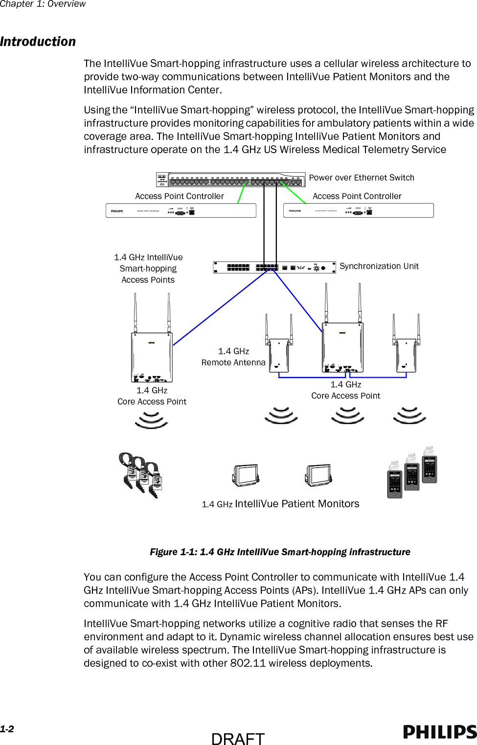
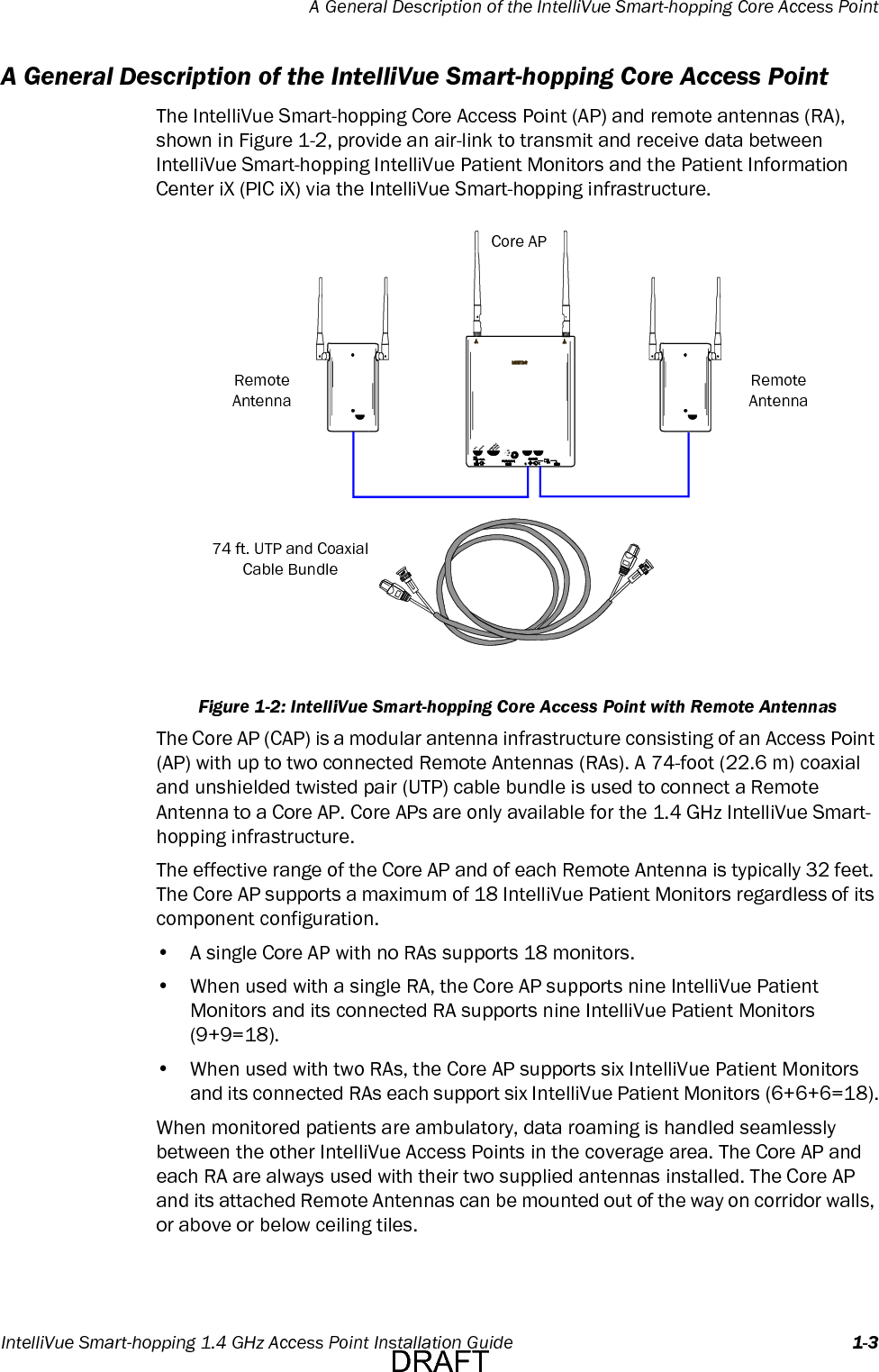
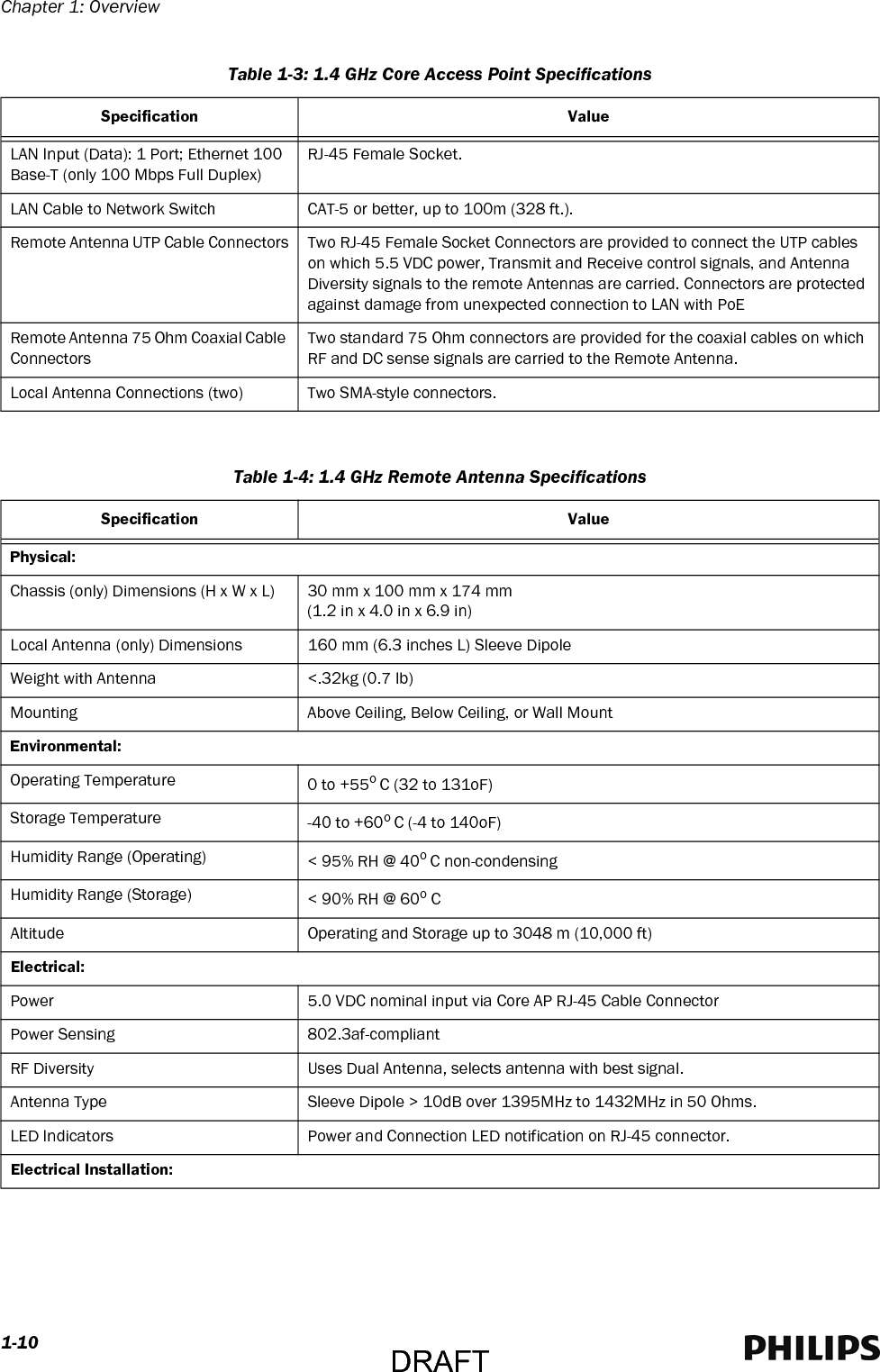
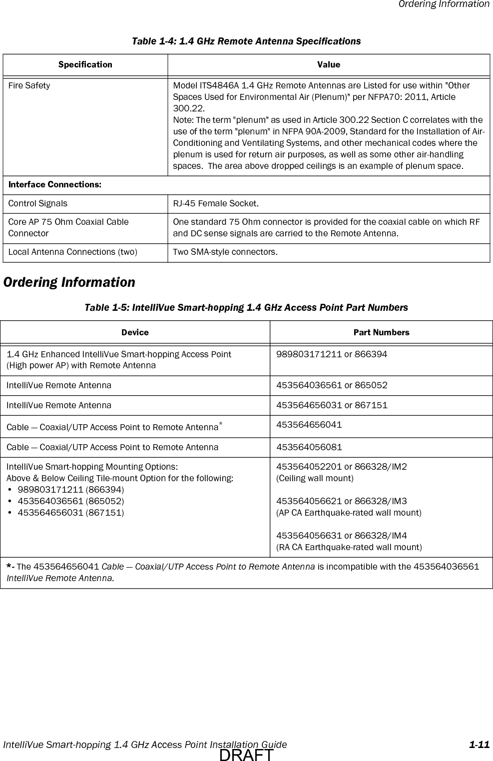
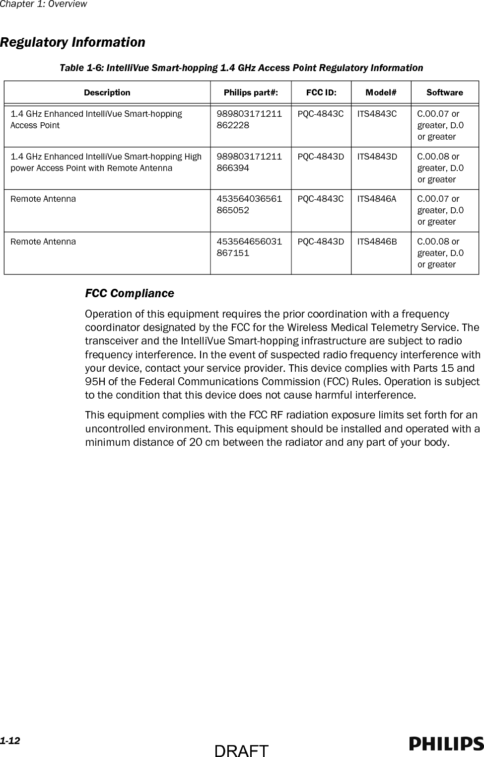
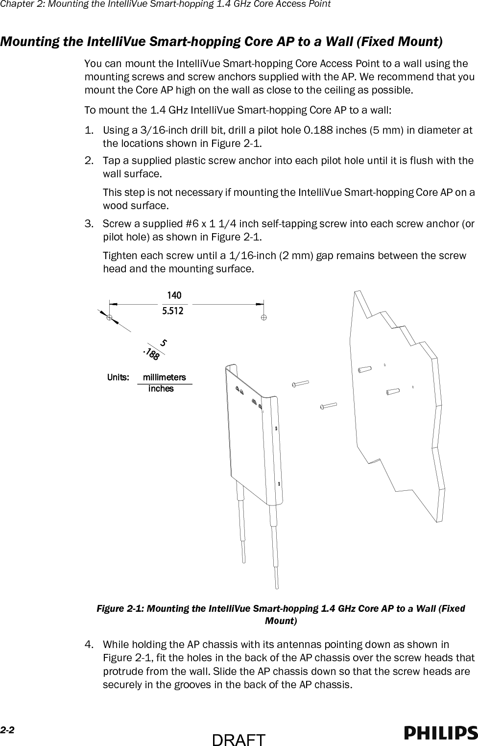
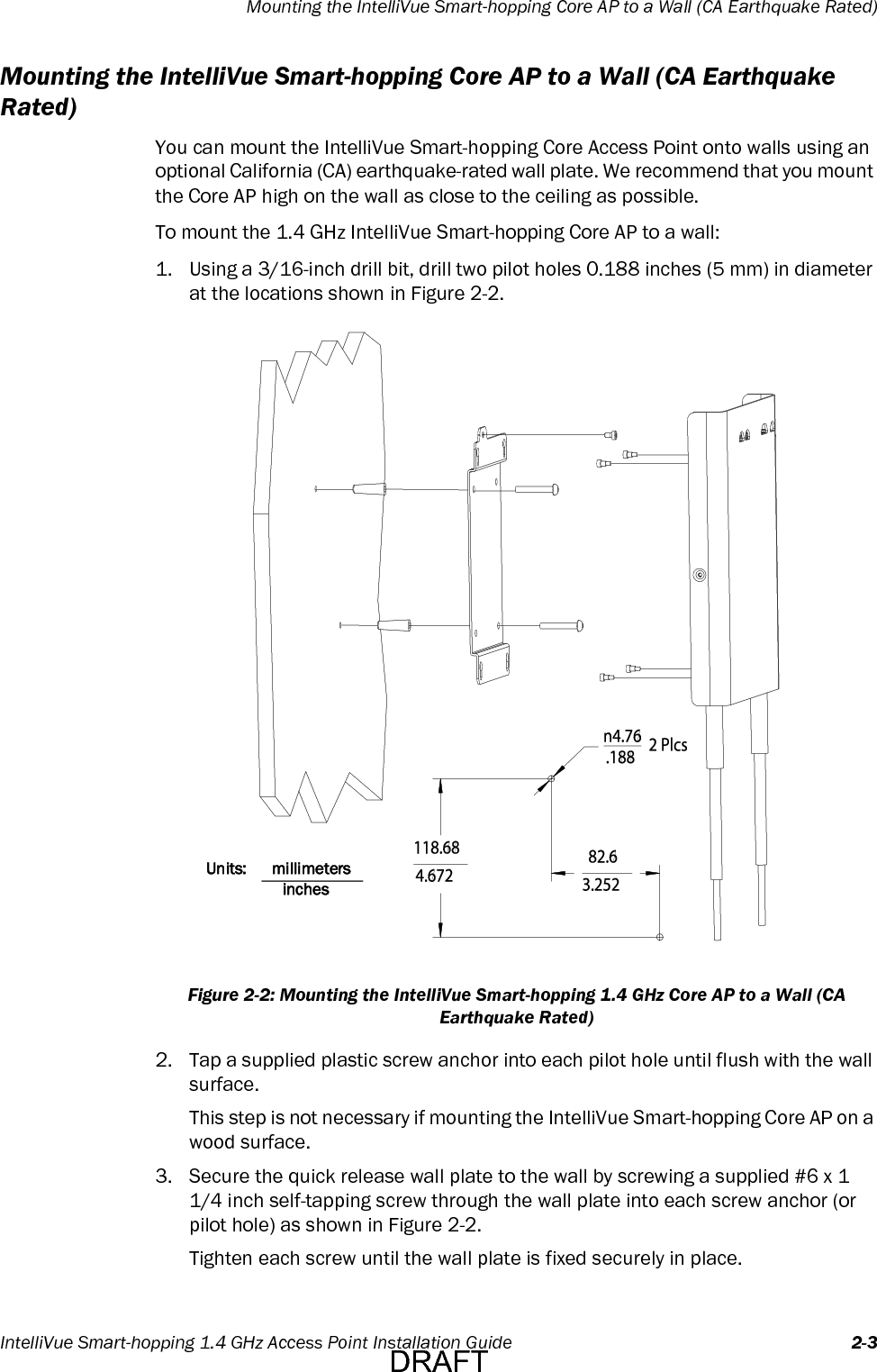
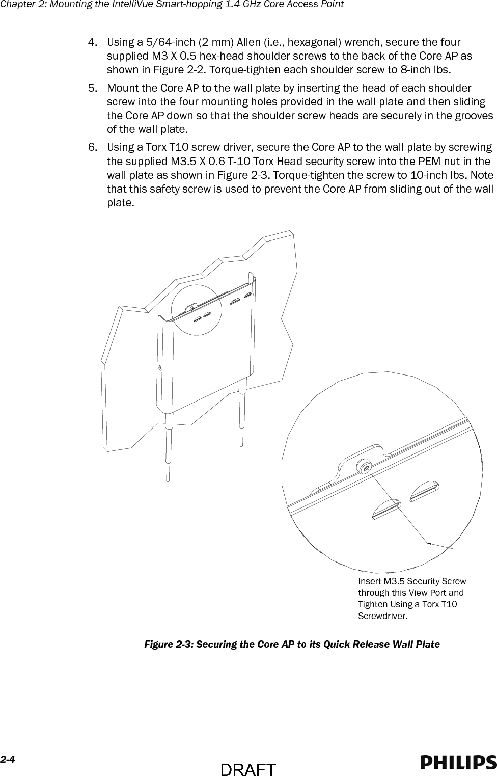
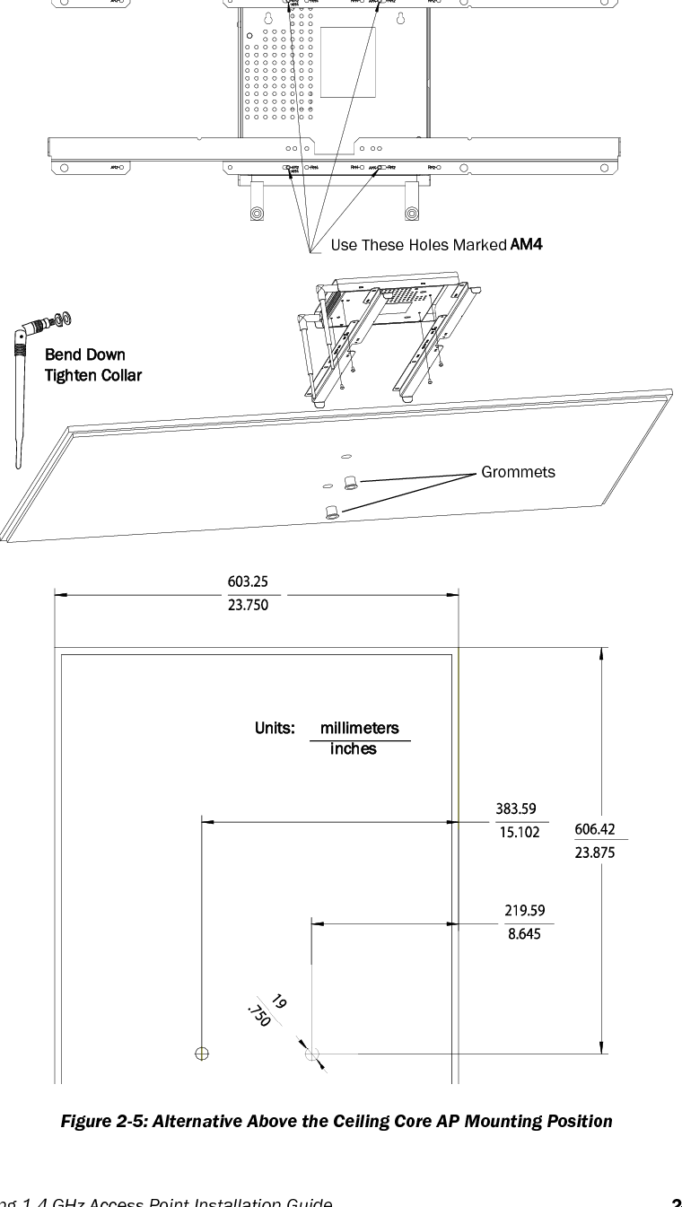
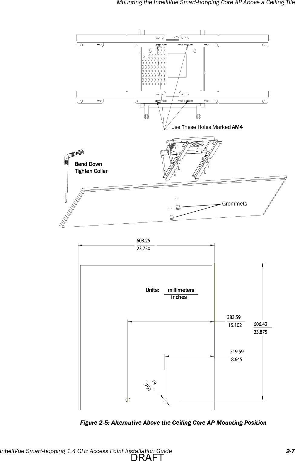
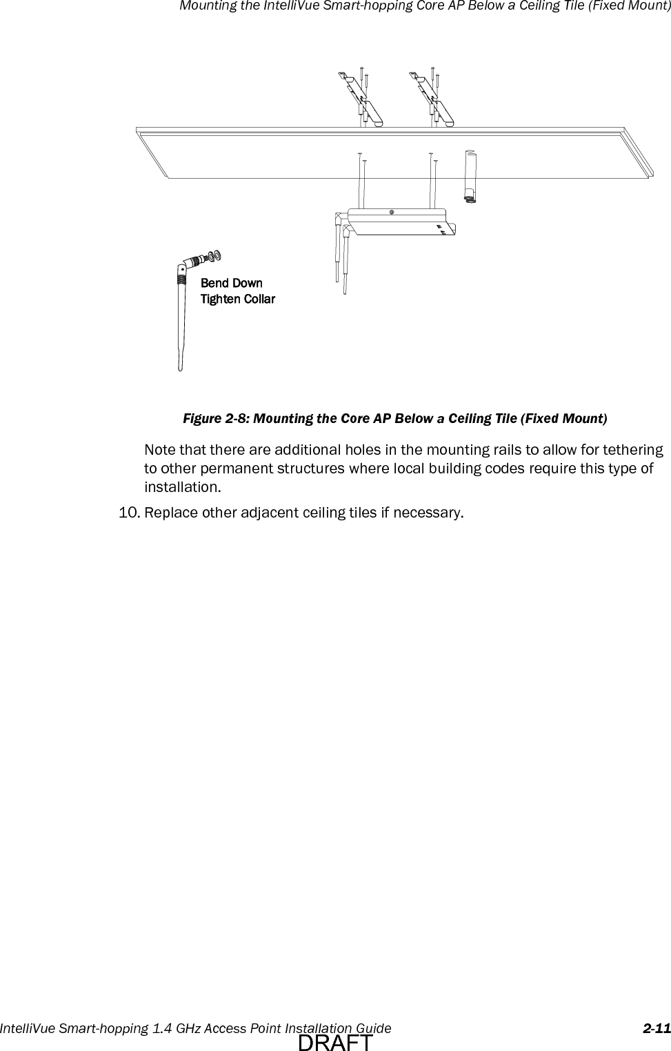
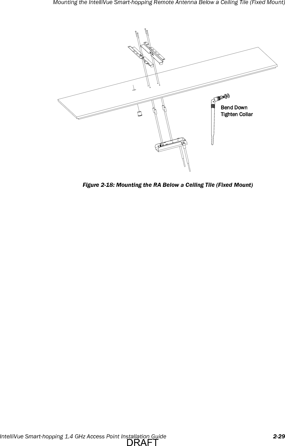
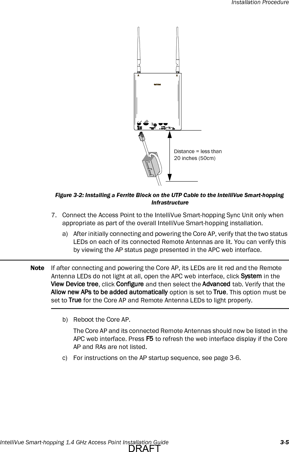
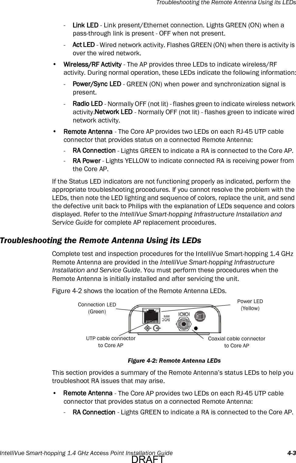
![1-4Chapter 1: OverviewCore AP Mounting OptionsWall-mounting hardware is standard. An optional above/below ceiling tile mount kit (P/N 866328 Option IM2 [453564052201]) is available for both the Core AP and its Remote Antennas.Power SourceThe IntelliVue Smart-hopping 1.4 GHz Core Access Point receives its 48V DC operating power source via its Ethernet LAN cabling from Power over Ethernet via the IntelliVue Smart-hopping Sync Unit. The AP is not equipped with a power socket. The AP consumes less than 13.8W, and internally generates a variety of voltages used for its internal components.The CAT-5 UTP cable within the 74 ft.-cable bundle carries 5.5V DC power, Transmit and Receive control signals, and Antenna Diversity signals from the Core AP to a connected Remote Antenna.The 75 Ohm coaxial cable within the 74 ft.-cable bundle carries RF and DC sense signals from the Core AP to a connected Remote Antenna.Synchronization SignalThe Access Point receives a synchronization signal from a network of Sync Units that enables an IntelliVue Patient Monitor to hand over data seamlessly between APs within the coverage area when a patient is ambulatory and to transfer data to the IntelliVue Information Center without interruption. Each Sync Unit provides synchronization for up to 12 APs. The sync signal distributes the common reference clock signal needed by the IntelliVue Smart-hopping infrastructure.IntelliVue Patient Monitor MobilityThe IntelliVue Smart-hopping infrastructure supports seamless roaming of IntelliVue Patient Monitors within the area of coverage. This roaming is accomplished via communications between the IntelliVue Patient Monitors and the Access Points (AP) as follows.As an IntelliVue Patient Monitor is moved around a building, it automatically monitors the quality of the wireless link to its current AP (and it also detects the presence of other APs). When the quality starts to deteriorate, the IntelliVue Patient Monitor automatically establishes a new connection to another AP.The IntelliVue Patient Monitor remains connected to two APs for a finite time, and thus the same data is received by these APs. During this time, information for header compression and other data for the connection is routed to the new AP.One of the two APs subsequently releases the radio connection. If a packet is in progress when a handover occurs, then the packet is reassembled co-operatively between the two APs.The PIC or PIC iX receives an unbroken flow of complete IP packets.DRAFT](https://usermanual.wiki/Philips-Medical-Systems-North-America/4843D/User-Guide-3396196-Page-14.png)