Philips Medical Systems North America M2601B Medical Telemetry Transmitter User Manual tele6
Philips Medical Systems North America Co. Medical Telemetry Transmitter tele6
UserManual.wiki
>
Philips Medical Systems North America
>
M2601B User Manual
Instructions for Use
Navigation menu
Upload a User Manual
Namespaces
Wiki Guide
HTML
PDF
Info
Views
User Manual
Discussion / Help
Navigation
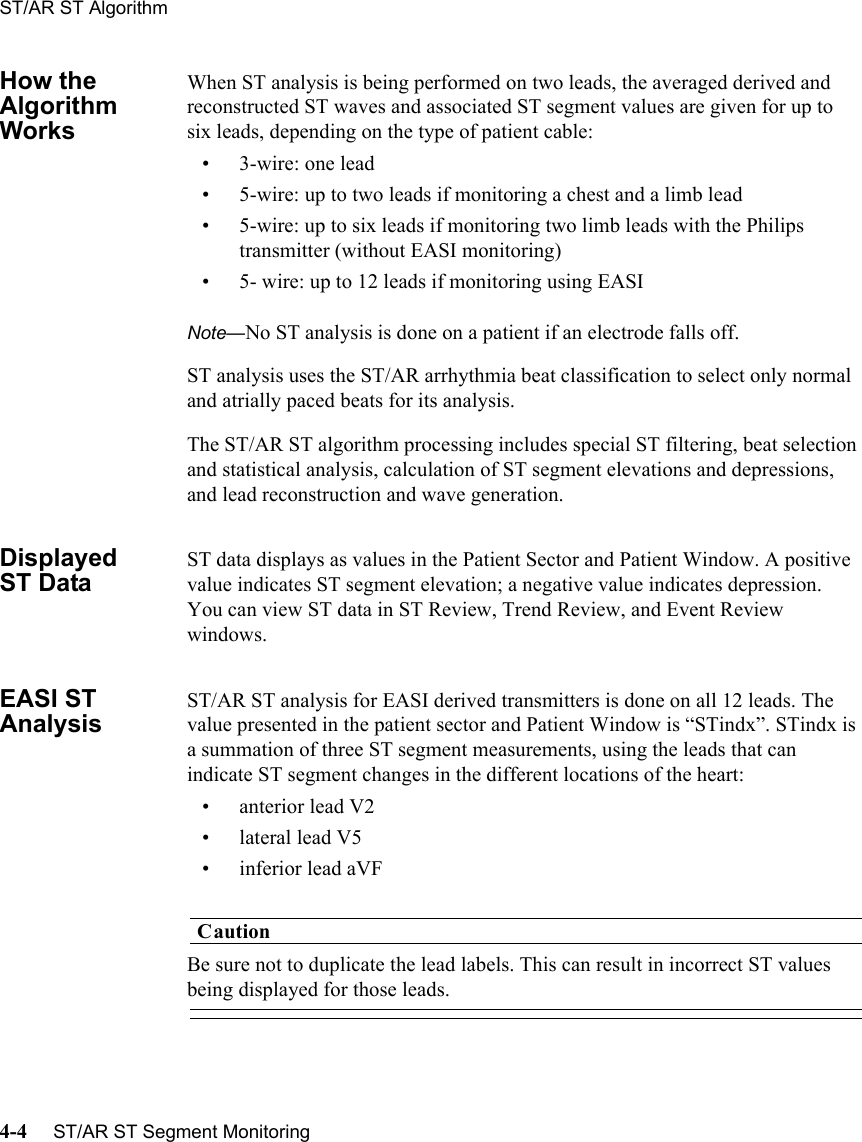
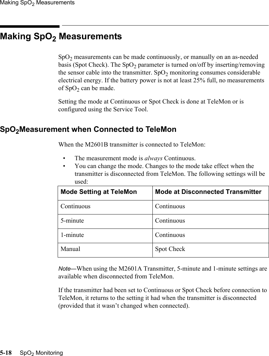
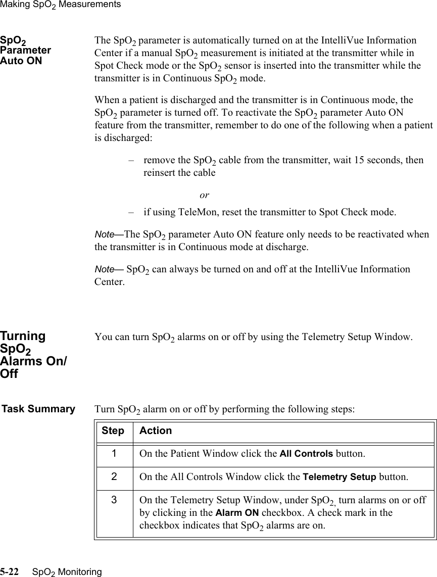
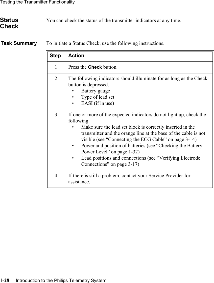
![Product Safety InformationviiiWarningWarningST/AR ARRHYTHMIA SAFETY FOR ALL PATIENTSDuring complete heart block or pacemaker failure (to pace or capture), tall P-waves (greater than 1/5 of the average R-wave height) can be erroneously counted by the arrhythmia algorithm, resulting in missed detection of cardiac arrest.Learning/Relearning--If you initiate learning during ventricular rhythm, the ectopics can be incorrectly learned as the normal QRS complex. This can result in missed detection of subsequent events of V-Tach and V-Fib.--When using EASI ECG monitoring, Relearn happens automatically when there is a LEADS OFF technical alarm. If learning takes place during ventricular rhythm, the ectopics can be incorrectly learned as the normal QRS complex. This can result in missed detection of subsequent events of V-Tach and V-Fib. Be sure to check the beat labels and initiate a relearn to correct. Therefore, when a technical alarm is generated:1. Respond to the technical alarm [for example, reconnect the electrode(s)].2. Ensure that the arrhythmia algorithm is labeling beats correctly.](https://usermanual.wiki/Philips-Medical-Systems-North-America/M2601B/User-Guide-463955-Page-8.png)

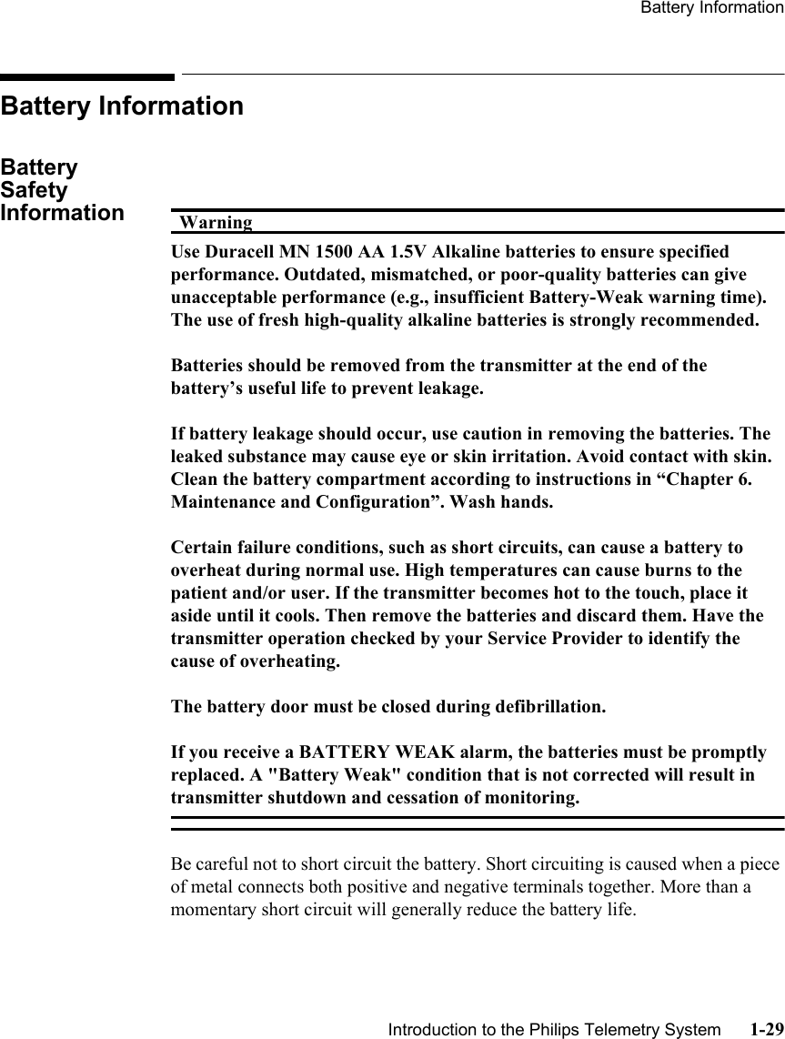

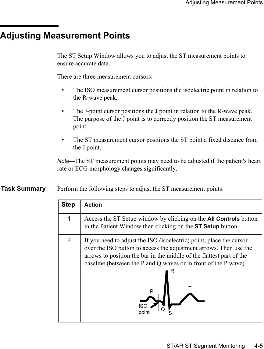
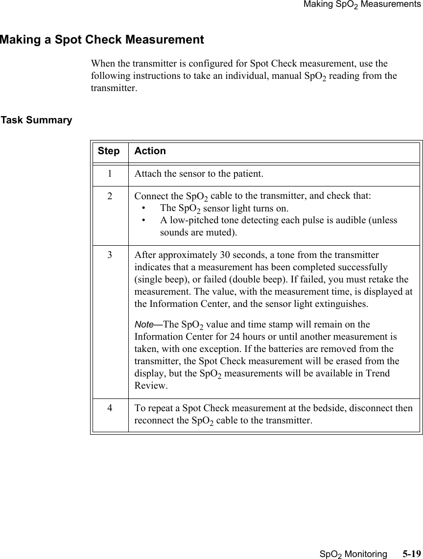
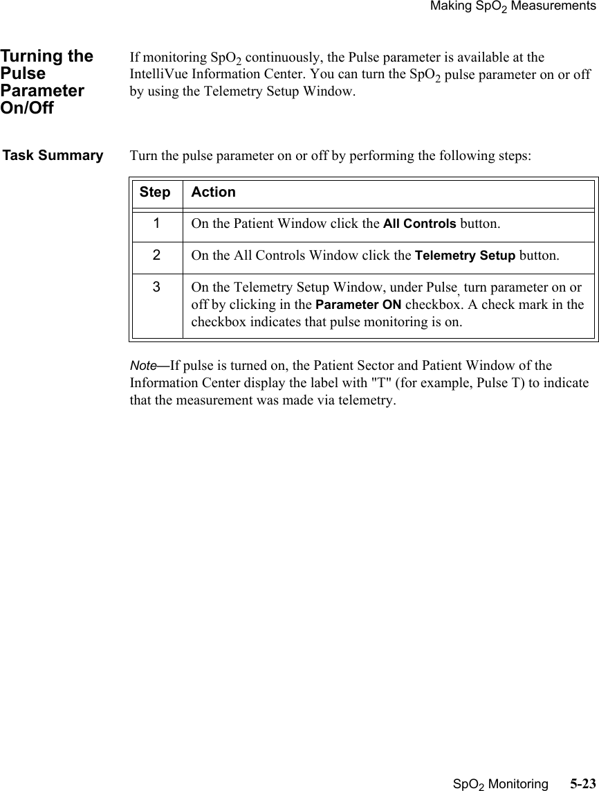
![ST/AR Arrhythmia AnalysisECG & ST/AR Measurement 3-31ST/AR Arrhythmia Safety Information WarningWarningFOR ALL PATIENTSDuring complete heart block or pacemaker failure (to pace or capture), tall P-waves (greater than 1/5 of the average R-wave height) can be erroneously counted by the arrhythmia algorithm, resulting in missed detection of cardiac arrest.Learning/Relearning--If you initiate learning during ventricular rhythm, the ectopics can be incorrectly learned as the normal QRS complex. This can result in missed detection of subsequent events of V-Tach and V-Fib.--When using EASI ECG monitoring, Relearn happens automatically when there is a LEADS OFF technical alarm. If learning takes place during ventricular rhythm, the ectopics can be incorrectly learned as the normal QRS complex. This can result in missed detection of subsequent events of V-Tach and V-Fib. Be sure to check the beat labels and initiate a Relearn to correct.1. Respond to the technical alarm [for example, reconnect the electrode(s)].2. Ensure that the arrhythmia algorithm is labeling beats correctly.](https://usermanual.wiki/Philips-Medical-Systems-North-America/M2601B/User-Guide-463955-Page-99.png)