Philips Medical Systems North America MX40WLAN2 INTELLIVUE MX40 WLAN2 PATIENT WORN DEVICE User Manual MX40 IFU Athens
Philips Medical Systems North America Co. INTELLIVUE MX40 WLAN2 PATIENT WORN DEVICE MX40 IFU Athens
USERS MANUAL

IntelliVue MX40
Instructions for Use
Release B.0
Draft Copy
ii
Notice
Proprietary Information
This document contains proprietary information, which is protected by
copyright.
First Edition 2012
4535 643 15721
Copyright
Copyright © 2012 Koninklijke Philips Electronics N.V. All rights reserved.
Reproduction in whole or in part is prohibited without the prior written
consent of the copyright holder. Philips Medical Systems Nederland B.V.
reserves the right to make changes in specifications and/or to discontinue any
products at any time without notice or obligation and will not be liable for any
consequences resulting from the use of this publication.
This product contains software licensed under an open source license. For
acknowledgments, license texts and source code, please refer to the IntelliVue
Information Center iX M3290B Software\References\README.pdf.
Windows ® is a registered trademark of Microsoft Corporation in the United
States and other countries.
EASI is a trademark of Zymed Inc.
OxiCliq ® and OxiMax ® are registered trademarks of Nellcor Incorporated.
Duracell ® is a registered trademark of Procter & Gamble Incorporated.
STERRAD ® is a registered trademark of Advanced Sterilization Products.
GORE-TEX ® is a registered trademark of W.L. Gore & Assoc. Incorporated.
Tone modulation is licensed under US patent 4,653,498 from Nellcor Puritan
Bennett Incorporated.
Manufacturer
Philips Medical Systems
3000 Minuteman Road
Andover, MA 01810-1099
(978) 687-1501
Printed in USA
Document number
Draft Copy

iii
4535 643 15721
Warranty
The information contained in this document is subject to change without
notice. Philips Medical Systems makes no warranty of any kind with regard to
this material, including, but not limited to, the implied warranties or
merchantability and fitness for a particular purpose. Philips Medical Systems
shall not be liable for errors contained herein or for incidental or consequential
damages in connection with the furnishing, performance, or use of this
material.
FCC
This device complies with Part 15 and/or Part 95 of the FCC Rules. Operation
is subject to the following two conditions: (1) these devices may not cause
harmful interference, and (2) these devices must accept any interference
received, including interference that may cause undesired operation.
Changes and modifications not expressly approved by Philips Medical
Systems can void your authority to operate this equipment under Federal
Communications Commission's rules
Protecting Personal Information
It is recommended that customers have policies and procedures for the proper
handling of personal or sensitive information, ePHI (electronic protected
health information) and PHI (protected health information), which will
maintain the confidentiality, integrity, and the availability of these types of
data. Any organization using this product should implement the required
protective means necessary to safeguard personal information consistent with
each applicable country law, code and regulation; and consistent with their
developed and maintained internal policies and procedures.
While handling personal information is outside the scope of this document; in
general, each organization is responsible for identifying:
Who has access to personal data and under what conditions an individual
has authorization to use that data.
What security controls are in place to protect personal and sensitive data.
How the data is stored and the conditions by which it is stored.
How the data is transmitted and the conditions under which that data is
transmitted.
Draft Copy

iv
Protecting personal health information is a primary component of a security
strategy. Personal and sensitive information should be protected according to
the applicable laws, regulations and directives, such as HIPAA, PIPEDA
and/or Council of the European Union security and privacy rules.
Compliance
Uses of the system for purposes other than those intended and expressly
stated by the manufacturer, as well as incorrect use, incorrect operation, or
modifications made to the system without explicit approval from Philips, may
relieve the manufacturer (or his agent) from all or some responsibilities for
resultant noncompliance, damage or injury.
Printing History
New editions of this document will incorporate all material updated since the
previous edition. Update packages may be issued between editions and
contain replacement and additional pages to be merged by a revision date at
the bottom of the page. Note that pages which are rearranged due to changes
on a previous page are not considered revised.
The documentation printing date and part number indicate its current edition.
The printing date changes when a new edition is printed. (Minor corrections
and updates which are incorporated at reprint do not cause the date to
change.) The document part number changes when extensive technical
changes are incorporated.
First Edition February 2012
Document Conventions
In this guide:
Warnings
Warning
A Warning alerts you to a potential serious outcome, adverse event or safety
hazard. Failure to observe a warning may result in death or serious injury to
the user or patient.
Draft Copy

v
Cautions
Caution
A Caution alerts you to where special care is necessary for the safe and
effective use of the product. Failure to observe a caution may result in minor
or moderate personal injury or damage to the product or other property, and
possibly in a remote risk of more serious injury.
Notes
A Note contains additional information on the product's usage.
Draft Copy
vi
Draft Copy
Contents 1
Contents
1. Introducing the IntelliVue MX40 1-1
MX40 Features -------------------------------------------------------------------------- 1-2
MX40 Models ---------------------------------------------------------------------------- 1-3
MX40 Release B.0 Compatibility --------------------------------------------------- 1-4
2. What's New? 2-1
New Features and Enhancements------------------------------------------------- 2-2
3. Product Safety 3-1
General Safety -------------------------------------------------------------------------- 3-2
Safety Symbols & Other Marks ----------------------------------------------------- 3-5
4. Basic Operation 4-1
Controls, Indicators and Connectors ---------------------------------------------- 4-2
MX40 Controls and Indicators -------------------------------------------------- 4-2
Multi-Function Button ----------------------------------------------------------- 4-3
Silence Alarm Button ----------------------------------------------------------- 4-3
SmartKeys Button --------------------------------------------------------------- 4-3
Main Screen Button ------------------------------------------------------------- 4-4
SmartKeys ------------------------------------------------------------------------- 4-4
Alarms Area ----------------------------------------------------------------------- 4-5
Patient Information Area ------------------------------------------------------- 4-6
Paced Status --------------------------------------------------------------------- 4-6
Display Lock ---------------------------------------------------------------------- 4-6
Status Area ------------------------------------------------------------------------ 4-7
Operating and Navigating ------------------------------------------------------------ 4-8
Power-On Self Test --------------------------------------------------------------- 4-8
Navigating --------------------------------------------------------------------------- 4-8
Selecting Display Elements ----------------------------------------------------- 4-8
Locking the Display---------------------------------------------------------------- 4-9
Measurement Area ---------------------------------------------------------------- 4-9
Measurement Area Display Configurations --------------------------------- 4-9
Connecting/Disconnecting the Patient Cable ----------------------------- 4-10
Understanding Settings -------------------------------------------------------------- 4-12
Changing Measurement Settings --------------------------------------------- 4-12
ECG Settings at the MX40 ----------------------------------------------------- 4-12
Waveform Settings at the MX40 ---------------------------------------------- 4-13
Battery Information -------------------------------------------------------------------- 4-14
Battery Safety Information ------------------------------------------------------ 4-14
Lithium-ion Rechargeable Battery Care ------------------------------------ 4-15
Lithium-ion Rechargeable Battery Handling Precautions ------------ 4-15
Lithium-ion Rechargeable Battery Storage ------------------------------ 4-16
Draft Copy
2 Contents
Inserting/Removing Batteries ------------------------------------------------- 4-16
Inserting Batteries ---------------------------------------------------------------- 4-17
Removing the Batteries -------------------------------------------------------- 4-19
Battery Charge Status ---------------------------------------------------------- 4-20
Lithium-ion Rechargeable Battery Charge Status -------------------- 4-20
AA Battery Charge Status --------------------------------------------------- 4-21
Pouch Use ------------------------------------------------------------------------------ 4-22
Securing the Pouch-------------------------------------------------------------- 4-22
Showering -------------------------------------------------------------------------- 4-24
Telemetry Mode Use ---------------------------------------------------------------- 4-26
Monitoring Mode Use ---------------------------------------------------------------- 4-27
Briefing the Patient ------------------------------------------------------------------- 4-28
5. Alarms 5-1
Alarms Overview ------------------------------------------------------------------------ 5-2
Visual Alarm Indicators ----------------------------------------------------------- 5-3
Alarm Message ------------------------------------------------------------------- 5-3
Alarm Indicator ------------------------------------------------------------------- 5-4
Flashing Numeric ---------------------------------------------------------------- 5-4
Audible Alarm Indicators when in Monitoring Mode ---------------------- 5-5
Traditional Audible Alarms (HP/Agilent/Philips/Carenet) -------------- 5-5
ISO/IEC Standard Audible Alarms ------------------------------------------ 5-5
Acknowledging Alarms ----------------------------------------------------------- 5-6
Pausing or Switching Off Alarms----------------------------------------------- 5-6
To Pause All Alarms ------------------------------------------------------------ 5-6
While Alarms are Paused ----------------------------------------------------- 5-7
Restarting Paused Alarms ---------------------------------------------------- 5-7
Alarm Limits ------------------------------------------------------------------------- 5-7
Viewing Individual Alarm Limits ---------------------------------------------- 5-8
Reviewing Alarms ------------------------------------------------------------------ 5-8
Review Alarms Window -------------------------------------------------------- 5-8
Alarm Reminders ---------------------------------------------------------------- 5-8
Latching Alarms -------------------------------------------------------------------- 5-9
Alarm Latching Behavior --------------------------------------------------------- 5-9
Alarm Behavior at Power On ---------------------------------------------------- 5-9
Physiologic Alarms ------------------------------------------------------------------- 5-10
Technical Alarms (INOPs) --------------------------------------------------------- 5-14
6. ECG and Arrhythmia Monitoring 6-1
ECG Safety Information--------------------------------------------------------------- 6-2
For Paced Patients ---------------------------------------------------------------- 6-3
Measuring ECG ------------------------------------------------------------------------- 6-5
Connecting and Positioning ECG Electrodes ----------------------------------- 6-6
Draft Copy
Contents 3
Selecting the Primary and Secondary ECG Leads ---------------------------- 6-8
Checking Paced Status --------------------------------------------------------------- 6-9
Understanding the ECG Display -------------------------------------------------- 6-10
Monitoring Paced Patients ---------------------------------------------------------- 6-11
Optimizing Lead Selection for Paced Patients ---------------------------- 6-11
Changing the Size of the ECG Wave -------------------------------------------- 6-12
Choosing EASI or Standard Lead Placement --------------------------------- 6-13
Derived 12-lead ECG----------------------------------------------------------------- 6-14
Hexad -------------------------------------------------------------------------------- 6-14
EASI ---------------------------------------------------------------------------------- 6-14
ECG Configuration -------------------------------------------------------------------- 6-15
ECG Leads Monitored --------------------------------------------------------------- 6-16
Reconstructed Leads ----------------------------------------------------------------- 6-18
Chest Electrode Placement --------------------------------------------------------- 6-19
3-Wire Placement --------------------------------------------------------------------- 6-20
5-Wire Placement (Standard Mode) ---------------------------------------------- 6-21
5-Wire Placement (EASI Mode) --------------------------------------------------- 6-22
6-Wire Placement --------------------------------------------------------------------- 6-23
Selecting Positions of Va and Vb Chest Leads --------------------------- 6-23
6-Wire Placement (Hexad Mode) ------------------------------------------------- 6-24
Monitoring during Leads Off -------------------------------------------------------- 6-25
ECG Fallback ---------------------------------------------------------------------- 6-25
Relearning -------------------------------------------------------------------------- 6-25
ST/AR Arrhythmia Monitoring ------------------------------------------------------ 6-27
ST/AR Arrhythmia Algorithm --------------------------------------------------- 6-27
Indications for Use ------------------------------------------------------------- 6-27
How the ST/AR Algorithm Works --------------------------------------------- 6-27
Aberrantly-Conducted Beats ------------------------------------------------ 6-28
Atrial Fibrillation Alarm -------------------------------------------------------- 6-28
Intermittent Bundle Branch Block ------------------------------------------ 6-29
ECG and Arrhythmia Alarm Overview --------------------------------------- 6-29
Using ECG Alarms --------------------------------------------------------------- 6-30
Extreme Alarm Limits for Heart Rate -------------------------------------- 6-30
Arrhythmia Alarm Settings --------------------------------------------------- 6-30
Yellow Arrhythmia Alarms ---------------------------------------------------- 6-31
Viewing Arrhythmia Waves -------------------------------------------------- 6-31
Arrhythmia Beat Labels ------------------------------------------------------- 6-32
Enhanced Arrhythmia Chain ------------------------------------------------- 6-33
Basic Arrhythmia Chain ------------------------------------------------------- 6-34
Learning ----------------------------------------------------------------------------- 6-34
Learning Phase ----------------------------------------------------------------- 6-34
Single Lead Analysis ---------------------------------------------------------- 6-35
Multilead Analysis -------------------------------------------------------------- 6-35
Multilead Analysis With Changes in One Lead ------------------------- 6-35
Draft Copy
4 Contents
EASI ECG Monitoring -------------------------------------------------------- 6-36
Initiating Arrhythmia Relearning Manually --------------------------------- 6-36
ST/AR ST Analysis Algorithm ----------------------------------------------------- 6-37
Introduction ------------------------------------------------------------------------ 6-37
The Measurements -------------------------------------------------------------- 6-38
Overview --------------------------------------------------------------------------- 6-38
Turning ST or STE On and Off ----------------------------------------------- 6-38
Displayed ST Data --------------------------------------------------------------- 6-39
ST Lead Groups ------------------------------------------------------------------ 6-39
Derived 12 Lead ECG ---------------------------------------------------------- 6-40
EASI ST Analysis -------------------------------------------------------------- 6-40
HEXAD ST Analysis ---------------------------------------------------------- 6-41
ST Alarms -------------------------------------------------------------------------- 6-41
STE Alarms ------------------------------------------------------------------------ 6-41
QT Interval Monitoring --------------------------------------------------------------- 6-42
Intended Use ---------------------------------------------------------------------- 6-43
How the QT Analysis Algorithm Works ------------------------------------- 6-43
Adjusting QT Settings -------------------------------------------------------- 6-44
Limitations for QT Monitoring ----------------------------------------------- 6-45
7. Monitoring Pulse Rate 7-1
Pulse Rate Measurement ------------------------------------------------------------ 7-2
Displaying the Pulse Rate Measurement at the MX40 ----------------------- 7-3
8. Monitoring Respiration Rate (Resp) 8-1
Respiration Rate Measurement ----------------------------------------------------- 8-2
Resp Safety Information -------------------------------------------------------------- 8-3
Lead Placement for Monitoring Resp --------------------------------------------- 8-4
Optimizing Lead Placement for Resp ----------------------------------------- 8-4
Cardiac Overlay -------------------------------------------------------------------- 8-4
Abdominal Breathing -------------------------------------------------------------- 8-4
Displaying Resp on the MX40 ------------------------------------------------------- 8-5
9. SpO2 Monitoring 9-1
SpO2 Safety Information -------------------------------------------------------------- 9-2
SpO2 Information for the User -------------------------------------------------- 9-3
Pulse Oximetry Measurement ------------------------------------------------------- 9-5
SpO2 Sensors ----------------------------------------------------------------------- 9-6
Selecting an SpO2 Sensor ------------------------------------------------------- 9-6
Sensor Application Safety Information --------------------------------------- 9-7
Applying the Sensor --------------------------------------------------------------- 9-8
Connecting SpO2 Cables -------------------------------------------------------- 9-8
Tone Modulation Indication ------------------------------------------------------ 9-8
Signal Quality Indicator ----------------------------------------------------------- 9-8
Measuring SpO2 -------------------------------------------------------------------- 9-9
Draft Copy
Contents 5
Understanding SpO2 Alarms --------------------------------------------------- 9-10
10. Monitoring with other Assigned Devices 10-1
Assigning Devices --------------------------------------------------------------------- 10-3
Device Assignment at the Information Center ---------------------------- 10-3
Device Assignment at the MX40 ---------------------------------------------- 10-3
Device Assignment at the Patient Monitor --------------------------------- 10-4
Controls Available when Assigned to IntelliVue Cableless Measurements10-6
Controls Available when Assigned to IntelliVue Patient Monitors -------- 10-7
Networked Device Synchronized Settings -------------------------------------- 10-8
MX40 Display when Wirelessly Connected to a Patient Monitor --------- 10-9
11. Monitoring with the MX40 at the Information Center 11-1
MX40 Connection to the Information Center ----------------------------------- 11-2
MX40 Controls in the Patient Window (IIC) ------------------------------------ 11-3
MX40 Controls in the Patient Window (IIC iX) --------------------------------- 11-5
Locating the MX40 (Find Device) ------------------------------------------------- 11-7
Viewing Device Location and Location History (optional) ------------------ 11-8
Using the Device Location Client (optional - IIC only) ----------------------- 11-9
Patient Configurable Settings in Telemetry Setup -------------------------- 11-10
Unit Configurable Settings -------------------------------------------------------- 11-13
12. Operating with Information Center Release L or M 12-1
Display ----------------------------------------------------------------------------------- 12-2
Alarms ------------------------------------------------------------------------------------ 12-3
13. Trends 13-1
Viewing Vital Trend Information --------------------------------------------------- 13-2
14. Maintenance 14-1
Cleaning --------------------------------------------------------------------------------- 14-2
Cleaning Materials for the MX40 --------------------------------------------- 14-3
Disposing of the MX40 --------------------------------------------------------------- 14-5
Label Assignment for Replacement MX40 ------------------------------------- 14-6
Re-assigning an Equipment Label at the IntelliVue Information Center14-6
Re-assigning an Equipment Label at the IntelliVue Information Center
iX -------------------------------------------------------------------------------------- 14-7
Charging Lithium-ion Rechargeable Batteries --------------------------------- 14-8
Battery Power Indicators -------------------------------------------------------- 14-8
Charging Station LEDs -------------------------------------------------------- 14-8
Battery Status on the Charging Station Display ------------------------ 14-9
Battery Lifetime Management ------------------------------------------------- 14-9
Battery Disposal ----------------------------------------------------------------- 14-10
15. Safety Standards & Specifications 15-1
Regulatory Information --------------------------------------------------------------- 15-2
Software Hazard Prevention --------------------------------------------------- 15-2
Draft Copy
6 Contents
AC Power Source ---------------------------------------------------------------- 15-2
Industrie Canada Compliance (Canada) ----------------------------------- 15-2
Safety Standards ----------------------------------------------------------------- 15-2
Intended Use Statement ------------------------------------------------------- 15-3
Indications for Use --------------------------------------------------------------- 15-3
Intended Uses of MX40 -------------------------------------------------------- 15-3
Authorized EU Representative ----------------------------------------------- 15-4
Patient Population --------------------------------------------------------------- 15-4
Rx ------------------------------------------------------------------------------------ 15-4
Essential Performance --------------------------------------------------------- 15-4
Risk Management Considerations ------------------------------------------ 15-5
Electromagnetic Compatibility ----------------------------------------------------- 15-8
Reducing Electromagnetic Interference ------------------------------------ 15-9
Restrictions for Use-------------------------------------------------------------- 15-9
Electromagnetic Compatibility (EMC) Specifications ------------------- 15-9
Accessories Compliant with EMC Standards -------------------------- 15-9
Electromagnetic Emissions --------------------------------------------------- 15-10
Electromagnetic Immunity ---------------------------------------------------- 15-10
Recommended Separation Distance -------------------------------------- 15-11
Electrosurgery Interference/Defibrillation/Electrostatic Discharge15-13
Restart Time ------------------------------------------------------------------- 15-13
Battery Specifications -------------------------------------------------------------- 15-14
Lithium-ion Battery Charge Time ------------------------------------------------ 15-17
Physical Specifications ------------------------------------------------------------- 15-18
MX40 1.4 GHz Smart-Hopping Radio ------------------------------------------ 15-19
MX40 2.4 GHz Smart-Hopping Radio ------------------------------------------ 15-20
MX40 Short-Range Radio --------------------------------------------------------- 15-22
MX40 2.4GHz WLAN Radio ------------------------------------------------------ 15-23
FCC and Industry Canada Radio Compliance -------------------------- 15-24
Environmental Specifications ----------------------------------------------------- 15-25
Measurement Specifications ----------------------------------------------------- 15-26
ECG -------------------------------------------------------------------------------- 15-26
ECG Performance Disclosure/Specifications ---------------------------- 15-27
Respiration ------------------------------------------------------------------------ 15-29
Respiration Alarm------------------------------------------------------------- 15-29
FAST SpO2 ----------------------------------------------------------------------- 15-30
SpO2 Sensor Accuracy -------------------------------------------------------- 15-31
A. Accessories A-1
MX40 Accessories --------------------------------------------------------------------- A-2
Pouches ------------------------------------------------------------------------------ A-2
Miscellaneous ----------------------------------------------------------------------- A-2
ECG Accessories ----------------------------------------------------------------------- A-3
Electrodes ---------------------------------------------------------------------------- A-3
Draft Copy
Contents 7
Leadsets and Patient Cables --------------------------------------------------- A-3
SpO2 Accessories ---------------------------------------------------------------------- A-5
Philips/Nellcor Disposable Sensors ------------------------------------------- A-5
Philips Reusable Sensors ------------------------------------------------------- A-5
Adapter Cables --------------------------------------------------------------------- A-6
B. Default Settings B-1
Alarm Default Settings ---------------------------------------------------------------- B-2
ECG, Arrhythmia, ST and QT Default Settings --------------------------------- B-3
Configuration Default Settings at the MX40 ------------------------------------- B-5
C. Sales and Support Offices C-1
Draft Copy
8 Contents
Draft Copy
Introducing the IntelliVue MX40 1-1
1. Introducing the IntelliVue
MX40
This section introduces the IntelliVue MX40 wearable patient monitor.
MX40 Features ........................................................................................... 1-2
MX40 Models ............................................................................................. 1-3
MX40 Release B.0 Compatibility ............................................................. 1-4
Draft Copy

MX40 Features
1-2 Introducing the IntelliVue MX40
MX40 Features
Easy for clinicians to use and comfortable for patients to wear.
2.8" color, touch sensitive display.
Smart, multi-measurement cable system available for use with reusable
and single-patient use supplies.
FAST SpO2 (continuous, automatic or manual measurement).
Standard, EASI or Hexad ECG lead system selection.
Impedance-based Respiration measurement.
6-lead with two V-leads for diagnosing multiple cardiac abnormalities,
including wide-QRS complex tachycardias and acute myocardial
ischemia/infarction.
Local measurement trend/alarm history.
Local alarming for measurements (requires IntelliVue Information
Center Release N or later or IntelliVue Information Center iX).
Integrated radio for connection to an Information Center iX.
Integrated Short-Range Radio (SRR).
Communication with IntelliVue Patient Monitors and Cableless
Measurements via Short-Range Radio connection (MP5/MP5T/MP5SC,
MP2 and X2 monitors only).
Powered by three AA batteries or rechargeable lithium-ion battery
pack.
Note — The WLAN MX40 (Model Number 865352) is powered only by
the rechargeable lithium ion battery pack.
Audio feedback for out-of-range and lost device.
Battery gauge on device and at Information Center.
Alarm suspend and resume from standby at device and Information
Center.
Pouch with clear front that closes securely.
Note — Unlike a traditional bedside monitor which operates on AC power,
the MX40 is powered by battery and provides time-limited screen display
and local alarming.
Draft Copy

MX40 Models
Introducing the IntelliVue MX40 1-3
MX40 Models
The MX40 is available in three models (ECG only, ECG and FAST SpO2, or
ECG and SpO2 Ready (for future upgrade).
Draft Copy

MX40 Release B.0 Compatibility
1-4 Introducing the IntelliVue MX40
MX40 Release B.0 Compatibility
The MX40 is compatible for use with IntelliVue Information Center Release
N and IntelliVue Information Center iX Release A. Limited compatibility is
offered when used with IntelliVue Information Center Release L or M. See
the "Operating with Release L or M" chapter for more information.
The MX40 is compatible for use with IntelliVue Patient Monitors Release G
or later when wirelessly connected.
The MX40 is compatible for use with IntelliVue Cableless Measurements
Release A.1.
The MX40 is compatible for use with Access Point Controller 862147,
Release B.00.19 and Access Point Controller 865346, Release C.00.04.
The MX40 Patient Cable is compatible for use with IntelliVue Patient
Monitor platforms MP2/X2, MP5/MP5T/MP5SC, MP20/30 with MMS or X2,
MP40/50 with MMS or X2, MP60/70 with MMS or X2, MP80/90 with MMS
or X2, and MX800/700/600 with MMS or X2.
Draft Copy
What's New? 2-1
2. What's New?
This section lists the most important new features and improvements to the
MX40 and its user interface. Further information is provided in other
sections of this book.
You might not have all of these features, depending on the MX40
configuration purchased by your hospital.
New Features and Enhancements ........................................................... 2-2
Draft Copy

New Features and Enhancements
2-2 What's New?
New Features and Enhancements
Compatibility
The MX40 B.0 offers compatibility with the new IntelliVue Information
Center iX
Respiration
The MX40 now offers a Respiration Rate measurement (available with
the IntelliVue Information Center iX only).
Rotating Alarm Presentation
When multiple alarms are active, the MX40 will rotate the display of the
alarm message every three seconds (Only INOPS are displayed with
IntelliVue Information Center Release L or M).
Numeric Only Display
A new display orientation is available showing six numerics only. No
waveforms are shown (available with IntelliVue Information Center iX).
ECG Waveform Size Adjustment
The size of the ECG waveform can now be adjusted by touching the
waveform on the display.
Wireless LAN Availability
The MX40 is now available as a Wireless LAN device for 802.11 a/b/g
communication (for use with IntelliVue Information Center iX only).
ST and QT Measurement Analysis
ST and QT values can be displayed on the MX40 (available with
IntelliVue Information Center iX only).
Hexad
A 12-lead ECG derived from a 6-wire electrode leadset is available to
increase patient comfort and reduce interference (available with
IntelliVue Information Center iX only).
Draft Copy
Product Safety 3-1
3. Product Safety
This section consolidates the general safety warnings associated with the
IntelliVue MX40. These warnings are repeated throughout the book in
context where relevant.
Safety symbols and other markings on the MX40 are also described here.
General Safety ............................................................................................ 3-2
Safety Symbols & Other Marks ............................................................... 3-5
Draft Copy

General Safety
3-2 Product Safety
General Safety
Warnings
The MX40 operates exclusively via a wireless network connection,
thereforel, it should not be used for primary monitoring in applications
where momentary loss of the ECG is unacceptable at the Information
Center. It sends ECG and optionally pulse oximetry data to the
Information Center, where the Information Center displays real-time
patient data, provides alarm annunciation, data storage and review
applications. The ECG waveform data, alarms and optionally SpO2 can
always be viewed on the MX40 regardless of the connection to the
Information Center.
A wireless patient monitoring system will never be as reliable as a
patient monitoring system that transmits its signal through a wire, due
to the inherent nature of radio frequency and the many variables that
affect over-the-air communication. This factor should be considered
when electing to monitor patients using wireless technologies. If
occasional loss of ECG monitoring at the Information Center is not
clinically acceptable for certain patients, alternatives must be sought. As
the IntelliVue MX40 does not provide a wired network connection, we
would recommend the use of an IntelliVue patient monitor with a
wired connection to the Information Center for these patients.
For continued safe use of this equipment, it is necessary that the listed
instructions are followed. Instructions in this manual in no way
supersede established medical procedures.
Do not touch the patient, or table, or instruments, during defibrillation.
The battery door must be closed during defibrillation. These steps
protect the clinician from high defibrillator voltage.
This device is not to be used in the vicinity of electrosurgical units
because such use may interrupt or interfere with the transmission of
signals from the MX40.
This equipment is not suitable for use in the presence of a flammable
anesthetic mixture with air, or with oxygen or nitrous oxide.
This equipment is not suitable for use in an MRI environment.
Do not use patient cables with detachable lead wires that have exposed
male pins. Electrocution could result if these pins are plugged into AC
power.
Draft Copy

General Safety
Product Safety 3-3
Do not use patient cables or accessory cables and sensors if prior visual
inspection reveals cable damage or the presence of liquid, lint or dust
inside.
The system is not completely immune from radio interference although
it is designed to minimize interference. Sources of interference that may
be a problem include failing fluorescent lights and construction
equipment. See "Electromagnetic Compatibility p. 15-8". The product
should not be used next to or stacked with other equipment. If you
must stack the product, you must check that normal operation is
possible in the necessary configuration before the product is used on
patients.
Do not rely exclusively on the audible alarm system for patient
monitoring. Adjustment of alarm volume to a low level during patient
monitoring may result in patient danger. Remember that the most
reliable method of patient monitoring combines close personal
surveillance with correct operation of monitoring equipment.
If the MX40 enters a continuous "boot-up" cycle or the main display
does not appear or update, ensure that you are using a freshly charged
lithium-ion battery or new disposable batteries. If the batteries are fresh
and the device reboots or does not update, remove the device from
service and contact your service personnel.
Place the MX40 in a pouch or over clothing, or both, during patient use.
The device should not touch the patient’s skin during use.
Patients should be instructed not to open the battery compartment
while the MX40 is in use.
Failure on the part of the responsible individual hospital or institution
employing the use of this equipment to implement satisfactory
maintenance as needed may cause undue equipment failure and
possible health hazards.
Because the coverage range of Access Points can sometimes overlap,
including different floor levels, the IntelliVue Device Location feature is
not intended for use when attempting to locate a patient.
Draft Copy

General Safety
3-4 Product Safety
Short-range radio connections are subject to interruption due to
interference from other radio sources in the vicinity, including
microwaves, bluetooth devices, and DECT phones. Outside the
frequency band and 5% above and below, i.e. the exclusion band
according to IEC 60601-1-2, the short-range radio connection is immune
up to 3V/m in the frequency range from 80MHz to 2.5 GHz. Depending
on the strength and duration of the interference, the interruption may
occur for an extended period. Any interruption of the signal due to
interference, moving out of range, or for other reasons is indicated with
a Tele Disconnected INOP message on the IntelliVue Patient Monitor.
Caution
Philips recommends that when using a pouch to attach the MX40 to your
patient that you consider your patient's condition and are careful about
placement of the straps as the straps could present a strangulation hazard.
Draft Copy
Safety Symbols & Other Marks
Product Safety 3-5
Safety Symbols & Other Marks
The table below describes the safety symbols and other markings present on the MX40 and the lithium-ion
battery.
Label
Definition
FCC ID:
IC:
Federal Communications Commission
(FCC) ID
Industry Canada Number
GMDN:
Global Medical Device Nomenclature
Federal Communications Commission
(FCC)
Declaration of Conformity
Rechargeable Battery
CE Mark (MX40)
Compliance to Council Directive
93/42/EEC (Medical Device Directive) and
1995/5/EC (Radio Equipment and
Telecommunications Equipment Directive)
Symbol for Class 2 Radio Equipment
CE Mark (Rechargeable Lithium-ion
Battery)
Compliance to Council Directive
2004/108/EC (EMC Directive)
Non-Ionizing Radiation
Interference to electronic equipment may
occur in the vicinity of devices marked with
this symbol.
Draft Copy
Safety Symbols & Other Marks
3-6 Product Safety
Label
Definition
Disposal
Dispose of in accordance with the local
country’s requirements. 2002/96/EC
(Waste Electrical and Electronic
Equipment).
Follow operating instructions.
Prescription Device
CSA Mark for
Certified by CSA to the applicable
Canadian and US standards..
Defibrillation Proof
Patient connections are protected against
defibrillation (DEFIBRILLATION-PROOF)
and are a TYPE CF APPLIED PART.
Service Identification Number
Used to identify the equipment during a
call to Philips Healthcare (Service)
Serial Number
Used to identify the equipment during a
call to the Philips Healthcare (Service).
Reference Number
Indicates Philips Product Number
MAC Address
Manufacturer and Date of Manufacture
Battery Polarity
Draft Copy
Safety Symbols & Other Marks
Product Safety 3-7
Label
Definition
IPX Waterproof Rating
Protected against the effects of temporary
immersion in water.
2D Barcode
UL Listed Device
Listed by Underwriters Laboratories
Attention! See Instructions for Use.
Draft Copy
Safety Symbols & Other Marks
3-8 Product Safety
Draft Copy
Basic Operation 4-1
4. Basic Operation
This section gives you an overview of the IntelliVue MX40 and its
functions. It tells you how to perform tasks that are common to all
measurements, such as turning a measurement on and off, adjusting wave
size and information in preparation for use.
Familiarize yourself with all instructions including warnings and cautions
before starting to monitor patients. Read and keep the Instructions for Use
that come with any accessories as these contain additional important
information.
Controls, Indicators and Connectors ...................................................... 4-2
Operating and Navigating ....................................................................... 4-8
Understanding Settings .......................................................................... 4-12
Battery Information ................................................................................. 4-14
Pouch Use ................................................................................................. 4-22
Telemetry Mode Use ............................................................................... 4-26
Monitoring Mode Use ............................................................................. 4-27
Briefing the Patient .................................................................................. 4-28
Draft Copy
Controls, Indicators and Connectors
4-2 Basic Operation
Controls, Indicators and Connectors
This section describes the clinical controls of the IntelliVue MX40. These
controls include buttons, display icons, visual and auditory indicators,
ports, and safety labeling located on the front and back of the device.
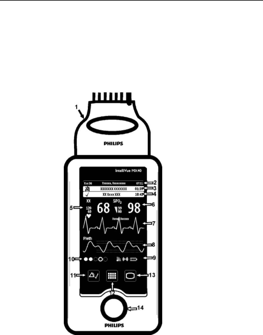
MX40 Controls and Indicators
1. Patient Cable
2. Patient Information Area
3. Active Alarms Area
4. INOP Area
5. Measurement Area 1
6. Measurement Area 2
7. Waveform 1
8. Waveform 2
9. Radio/Network/Battery Status Area
10. Leads Off Status Area
11. Silence Alarms Button
12. SmartKeys Button
13. Main Screen Button
14. Multi-Function Button
Draft Copy
Controls, Indicators and Connectors
Basic Operation 4-3
Multi-Function Button
Button
Function
Depending on configuration at the Information Center:
generates a Nurse Call;
Initiates a Delayed Recording;
Both, or;
None
Note — the Multi-Function Button does not operate
when paired with an IntelliVue Patient Monitor via the
short-range radio connection.
Silence Alarm Button
Button
Function
Initiates a local silence/acknowledgment of all
active alarms when enabled (IIC).
Initiates a global silence/acknowledgment of all
active alarms when enabled (IIC iX).
Silences the "Find Device" sound.
Note — Alarms at the MX40 can be silenced
from the Information Center. When silenced from
the Information Center, the alarm sound is not
silenced at the Information Center until it receives
feedback from the MX40. This may take several
seconds.
SmartKeys Button
Button
Function
Displays the SmartKey Menu on the touch screen.
Draft Copy
Controls, Indicators and Connectors
4-4 Basic Operation
Main Screen Button
Button
Function
Activates the Touch Display if touched for two
seconds.
Cycles through the display screens if touched
repeatedly.
Resumes from Standby.
When pressed from a sub-menu, returns display to the
Main Screen.
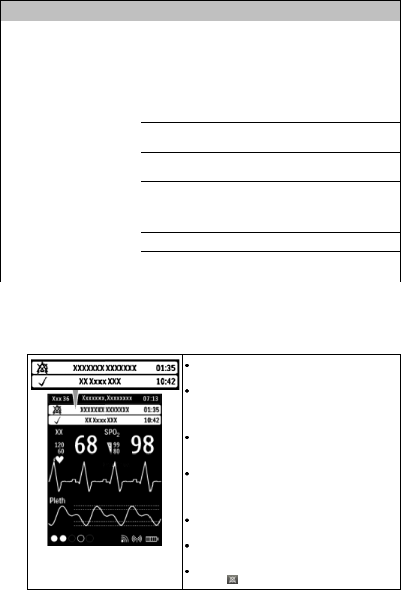
SmartKeys
The following table lists the SmartKeys available on the display of the
MX40.
Note—gray text on a SmartKey signifies that the item is unavailable.
SmartKey
Function
Start SpO2
Note — This
SmartKey is
unavailable when
SpO2 mode is
continuous.
Starts a manual SpO2 measurement.
Delay Record
Starts a delayed recording at the
Information Center.
Alarms
Alarm Volume setting. Review of up to 50
previous alarm conditions (entries are
stored during power cycle). Pause Alarms
for configured time period (if enabled at
the Information Center).
Mode: Telemetry /
Mode: Monitor
Toggles between modes. In Telemetry
Mode, display and audio are off; in
Monitor Mode, display and audio are
always on.
Draft Copy
Controls, Indicators and Connectors
Basic Operation 4-5
SmartKey
Function
Standby
Puts the device into Standby locally and
at the Information Center. Displays
purchased/enabled product options. To
resume from Standby, touch the Main
Screen button.
Add/Remove
Displays available monitors and IntelliVue
Cableless Measurements to assign to via
the short-range radio.
Print Reports
Prints the pre-configured report as
designated at the Information Center.
Vitals Trends
View up to 24 hours of tabular trend data.
One hour standard. 24 hours optional.
Setup Screen
Determines time period that the display
remains active after user interaction or
whether the display is always On or
always Off.
Lock/Unlock
Locks/Unlocks the display.
Op Mode
Selects either Monitoring, Demo, Config
or Service modes.
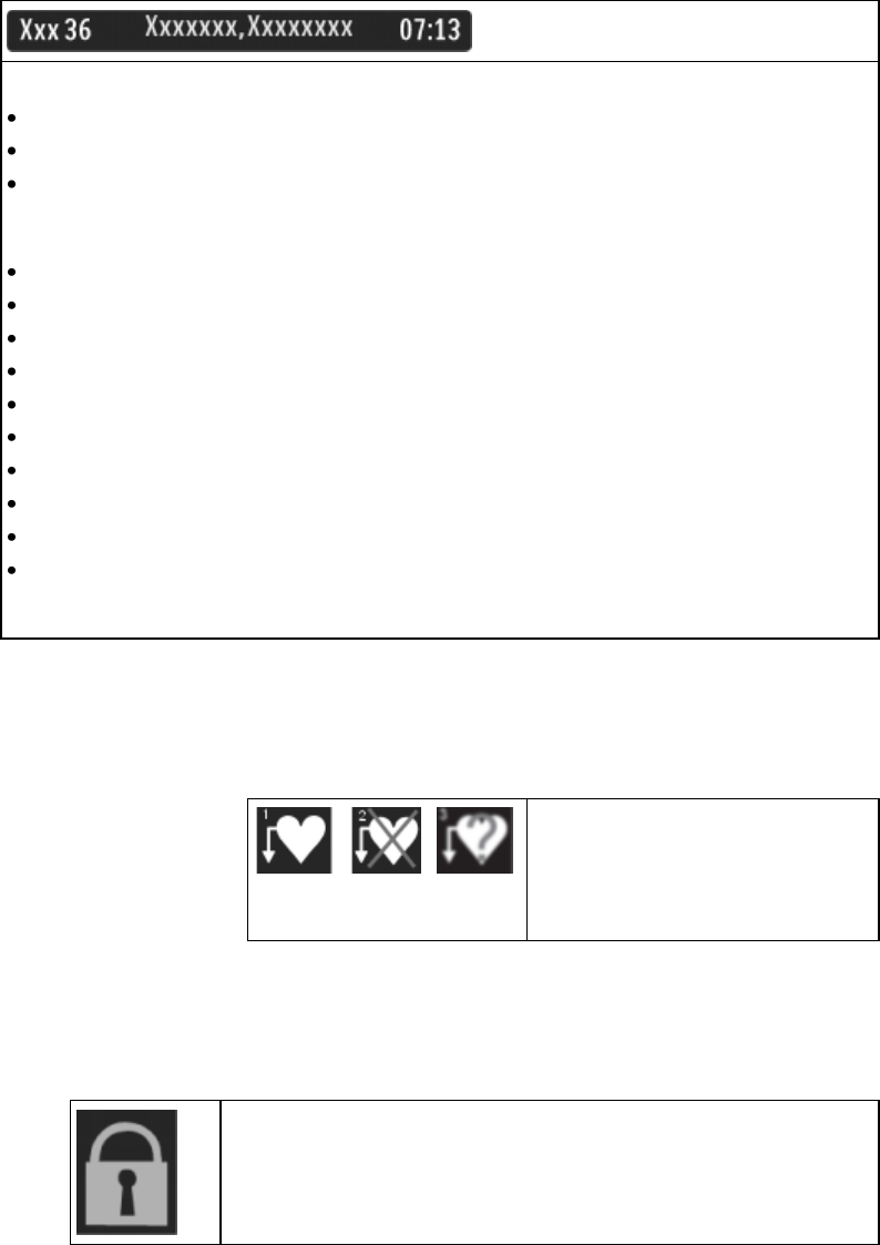
Alarms Area
The Alarm Area of the MX40 displays
physiological alarms and technical alarms.
A multiple alarm indicator (down arrow) is
displayed when multiple alarm conditions are
present and the alarm message rotates every 3
seconds.
A check mark in front of the alarm text signifies
that the alarm has been acknowledged by
touching the Silence Alarms button.
Alarm Indicators display in the Patient Information
Area in place of the time clock when alarm/INOP
conditions are present but have not been
acknowledged.
Touching the Alarms Area displays a list of all
active alarms.
The alarms paused icon communicates whether
the alarm system is on/off.
Local Alarm Audio is off when the alarm volume
symbol is present next to the time..
Draft Copy
Controls, Indicators and Connectors
4-6 Basic Operation
Patient Information Area
The Patient Information Area displays the following information:
Bed Label
Patient Name (up to 15 characters will display)
Time
Touching the Patient Information Area displays the Patient Demogr. menu which lists the
following:
Patient Name (Last, First, Middle)
Lifetime ID
Encounter ID
Patient Category
Paced Mode
Height
Weight
Date of Birth
Gender
Note — If you use an alternative ID, it will display at the Information Center and on printed
reports. It will not display at the MX40.
Paced Status
1. Pacing algorithm is on.
2. Pacing algorithm is off.
3. Pacing algorithm is on. Patient's
paced status is unknown.
Display Lock
The Lock symbol appears in the lower left of the display when the MX40
is in a locked state after five minutes of non-use. Locking the display
provides additional protection against accidental patient access. The
display is unlocked using the SmartKeys menu.
Draft Copy

Controls, Indicators and Connectors
Basic Operation 4-7
Status Area
The status area of the MX40 displays short-range radio
connection (optional) and system wireless connection status.
You can also view battery strength for the type of battery
used in the device, AA or rechargeable Li-on.
Draft Copy

Operating and Navigating
4-8 Basic Operation
Operating and Navigating
The principle method of operating your MX40 is via the Touch Display.
Almost every element on the display is interactive. Display elements
include measurement numerics, information fields, alarm fields,
waveforms, SmartKeys and menus.
Power-On Self Test
Once battery power is supplied, the MX40 performs a power-on self test to
check operational status prior to start-up. Should a failure be detected, an
INOP tone will sound and if possible, the appropriate INOP message for
the failure will be communicated to the Information Center and displayed
locally.
A successful power-on self test will then transition the MX40 to the start-up
screen. Selectable background colors can be configured and display on the
screen for assistance with device identification. This can be helpful when
devices are in a pooled use setting.
If the MX40 enters a continuous "boot-up" cycle or the main display does
not appear or update, ensure that you are using a freshly charged
lithium-ion battery or new disposable batteries. If the batteries are fresh and
the device reboots or does not update, remove the device from service and
contact your service personnel.
You must visually check that a waveform is present on the display. You can
access further status information is by touching the status area on the
display.
Navigating
Touching the Navigation Bar on the right of the display will scroll through
additional display items. Solid downward arrows indicate there are
additional elements that are not currently displayed. The arrows briefly
illuminate when touched. Your selection from the menu also illuminates
when touched.
Selecting Display Elements
Touch a display element to get to the actions linked to that element. For
example, touch the Patient Information element to call up the Patient Info
window, or touch the HR numeric to call up the Setup ECG menu. Touch
the ECG waveform to call up the wave selection menu.
Draft Copy

Operating and Navigating
Basic Operation 4-9
Locking the Display
To provide additional protection against accidental patient access to the
MX40, the display can be locked using the Lock SmartKey. When Lock is
selected, the SmartKey menu automatically changes to the Main Screen.
When Unlock is selected, you must close the SmartKey menu to return to
the Main Screen.
The display automatically locks when there is no interaction for the
configured time period (1-30 minutes with a default of 5 minutes).
Function
Display
Locked /
Active
Display
Locked /
Inactive
Display
Unlocked /
Active
Display
Unlocked /
Inactive
Display Touch
No
No
Yes
No
Main Screen
Button
No
Yes
Yes
Yes
SmartKeys Button
Yes
No
Yes
No
Silence Button
No
No
Yes
No
Measurement Area
The measurement area of the MX40 display is optimized to show available
parameter numerics, waveforms, and alarm limits. Each element is a touch
object and when you select it, further controls and menus become available.
Measurement Area Display Configurations
The display of your MX40 is configured/can operate in one of four available
orientations:
Portrait - No Waveforms and six Numerics (IIC iX only)
Portrait - One Waveform and four Numerics
Portrait - Two Waveforms and two Numerics (IIC Release N and IIC iX
only)
Landscape - Two Waveforms and three Numerics (IIC Release N and
IIC iX only)
Portrait - Viewable Chest Diagram and two Numerics
Draft Copy
Operating and Navigating
4-10 Basic Operation
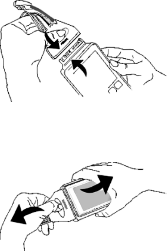
Connecting/Disconnecting the Patient Cable
The patient cable is connected to the MX40 as shown in the illustration
below.
When connecting to the MX40, there is a slight clicking sound that signifies
that the cable is securely connected.
Typically, the patient cable may be disconnected as shown below.
Draft Copy

Operating and Navigating
Basic Operation 4-11
During initial use of the MX40, the secure connection between the patient
cable and the device may be difficult to disconnect. Should this occur, use
the alternative procedure shown below.
Caution
Never disconnect the patient cable by pulling on the leadwires, as this may
damage wires over time.
Draft Copy

Understanding Settings
4-12 Basic Operation
Understanding Settings
Each aspect of how the MX40 works and looks is defined by a setting. There
are a number of different categories of settings, including:
Screen Settings - to define the selection and appearance of elements on
each individual display screen.
Measurement Settings - to define setting unique to each measurement,
e.g. high and low alarm limits.
Monitor Settings -including settings that affect more than one
measurement or display screen, for example alarm volume and alarm
pause time.
You must be aware that, although many settings can be changed during
use, permanent changes to settings can only be done in Configuration
Mode. All settings are restored to their default setting when the patient is
discharged or the MX40 is powered off.
Changing Measurement Settings
Each measurement has a setup menu in which you can adjust its settings.
You enter the setup menu by selecting the measurement numeric.
ECG Settings at the MX40
Setting
Description
Alarm Limits
Heart Rate alarm limits can be viewed locally at
the MX40. Limits set at the Information Center
(Release N or later or iX) are reflected at the
MX40 when connected on the network.
Primary
(used for arrhythmia analysis only)
(Set at IIC Release N or IIC iX. View only.)
I, II, III, aVR, aVL, aVF, V1-V9, MCL, V3R, V4R,
V5R. Available waveforms are based on lead set
type. Lead II is the default.
Secondary
(used for arrhythmia analysis only)
(Set at IIC Release N or IIC iX. View only.)
I, II, III, aVR, aVL, aVF, V1-V9, MCL, V3R, V4R,
V5R. Available waveforms are based on lead set
type. Lead V is the default.
Paced Mode
(Set at IIC Release N or IIC iX)
On, Off
Adjust Size
Set ECG gain to x1/2, x1, x2, x4
Arrhythmia
Initiate an Arrhythmia Relearn; View Arrhythmia
Alarm Limits; Turn Arrhythmia Annotation On/Off.
Lead Placement
Set EASI, Standard
Draft Copy

Understanding Settings
Basic Operation 4-13
Setting
Description
ECG
Set ECG On/Off
New Lead Setup
When IntelliVue Patient Monitor lead sets are in
use, select 3-wire, or 5-wire.
Va Lead
Shows position of Va, or C1, electrodes. Choices
are V1-V9, v3R, V4R, V5R.
Vb Lead
Shows position of Vb, or C2, electrodes. Choices
are V1-V9, v3R, V4R, V5R.
Change Numeric
Selects parameter numeric to display in place of
current HR numeric.
Waveform Settings at the MX40
Setting
Description
Wave 1
Primary, Secondary, I, II, III, aVR, aVL, aVF,
V1-V9, MCL, V3R, V4R, V5R. Available
waveforms are based on patient cable type. Lead
II is the default. If Primary or Secondary are
selected, then the waveform displayed is the
waveform configured as primary or secondary for
arrhythmia analysis.
Wave 2
Primary, Secondary, I,II, III, aVR, aVL, aVF,
V1-V9, MCL, V3R, V4R, V5R, Pleth (if SpO2 is
available), Resp (if Resp is available). Available
waveforms are based on patient cable type. Lead
V is the default. If Primary or Secondary are
selected, then the waveform displayed is the
waveform configured as primary or secondary for
arrhythmia analysis.
Primary or secondary waveform configuration changes made at the
Information Center change the MX40.
Draft Copy

Battery Information
4-14 Basic Operation
Battery Information
Battery Safety Information
Warnings
The battery compartment door must be closed during defibrillation.
Use the Philips Rechargeable Lithium-ion Battery or 3 Duracell Alkaline
batteries, size AA, MN 1500, 1.5V, to ensure specified performance and
correct battery gauge reporting. Outdated, mismatched, or poor-quality
batteries can give unacceptable performance (e.g., insufficient
Battery-Low warning time). If you are using disposable batteries, the
use of fresh high-quality alkaline batteries is strongly recommended.
Certain failure conditions, such as short circuits, can cause a battery to
overheat during use. High temperatures can cause burns to the patient
and/or user. If the MX40 becomes hot to the touch, remove it from the
patient and place it aside until it cools. Then remove the batteries and
discard them. Have the MX40 checked by your service provider to
identify the cause of overheating.
If you receive a TELE BATTERY LOW, TELE BATTERY EMPTY,
REPLACE BATTERY T, or TELE BATTERY TEMP alarm, the batteries
must be promptly replaced. If these conditions are not corrected, they
will result in a device shutdown and cessation of monitoring.
Disposable batteries should be removed from the MX40 at the end of
the battery’s useful life to prevent leakage.
If battery leakage should occur, use caution in removing the battery.
The leaked substance may cause eye or skin irritation. Avoid contact
with skin. Clean the battery compartment according to the instructions
in the Maintenance section. Wash hands.
To eliminate the risk of electrical shock or burn, do not carry loose
batteries on your person, e.g. in clothing pockets.
Cautions
Use of AA Lithium batteries or batteries with terminal voltage >1.6V
may cause damage to the device.
When monitoring with the WLAN version of the MX40 (Model 865352),
the lithium-ion rechargeable battery is the only approved power source.
Use of AA disposable batteries is not supported.
Draft Copy

Battery Information
Basic Operation 4-15
Lithium-ion Rechargeable Battery Care
Care of the rechargeable battery begins when you receive a new battery for
use and continues throughout the life of the battery. The table below lists
battery care activities and when they should be performed.
Activity
When to Perform
Perform a visual inspection.
Before inserting a battery in the MX40.
Charge the battery.
Upon receipt, after use, or if a low battery
state is indicated. To optimize
performance, a fully (or almost fully)
discharged battery should be charged as
soon as possible.
Clean the battery
At each patient discharge, or in cases
when the battery is exposed to
contaminants.
Charge stored batteries to at least 90% of
their capacity every six months.
When not in use for an extended period
of time.
Decommission the battery
When any of the following INOPs are
displayed on the MX40:
TELE SERVICE BATTERY
TELE BATTERY TEMP
Rechargeable batteries are charged using the IntelliVue CL Charging
Station. For information on charging station use, see Charging Li-ion
Rechargeable Batteries p. 14-8 .
Note — The battery capacity of re-chargeable batteries degrades over time
and number of recharge cycles. Toward the end of its useful life, the battery
capacity may be reduced by 25-30%. If this reduced battery life is
unacceptable based on your use model, Philips recommends replacing the
rechargeable battery sooner.
Lithium-ion Rechargeable Battery Handling Precautions
Lithium-ion batteries store a large amount of energy in a small package.
Use caution when handling the batteries; misuse or abuse could cause
bodily injury and/or equipment damage.
Do not short circuit - take care that the terminals do not contact metal
(e.g. coins) or other conductive materials during transport and storage.
Do not crush, drop or puncture - mechanical abuse can lead to internal
damage and internal short circuits that may not be visible externally.
Do not apply reverse polarity.
Draft Copy

Battery Information
4-16 Basic Operation
Do not incinerate batteries or expose them to temperatures above 60oC
(140oF).
If a battery has been dropped or banged against a hard surface, whether
damage is visible externally or not:
discontinue use.
dispose of the battery in accordance with the disposal instructions.
Lithium-ion Rechargeable Battery Storage
When storing rechargeable batteries, make sure that the battery terminals
do not come into contact with metallic objects or other conductive
materials.
If batteries are stored for an extended period of time, they should be stored
in a cool, dry place, ideally at 15oC (60oF), with a state of charge of 20% to
90%. Storing batteries in a cool place slows the aging process.
The batteries should not be stored at a temperature outside the range of
-20oC (-4oF) to 50oC (122oF).
Stored batteries should be should be charged to at least 90% of their
capacity every 6 months. They should be charged to full capacity prior to
use.
Note — Storing batteries at temperatures above 38oC (100oF) for extended
periods of time could significantly reduce the batteries' life expectancy.
Inserting/Removing Batteries
Warning
Arrhythmia relearning is initiated whenever the MX40's batteries are
removed for one minute or longer. Be sure to check your patient’s
arrhythmia annotation for accuracy whenever relearn has occurred.
Caution
Remove the batteries before storing the MX40 for an extended period of
time.
Draft Copy

Battery Information
Basic Operation 4-17
The battery compartment is located on the back of the MX40, accessible by
opening the compartment door from the bottom. It accommodates three
AA 1.5V Alkaline batteries or the Philips Rechargeable Lithium-ion battery.
Only these batteries should be used.
Note— Lithium-ion batteries should be fully charged prior to first use.
Important— Do not use other rechargeable batteries. Use of this type of
battery will adversely affect:
Battery gauge performance
Battery low warnings
Battery life performance
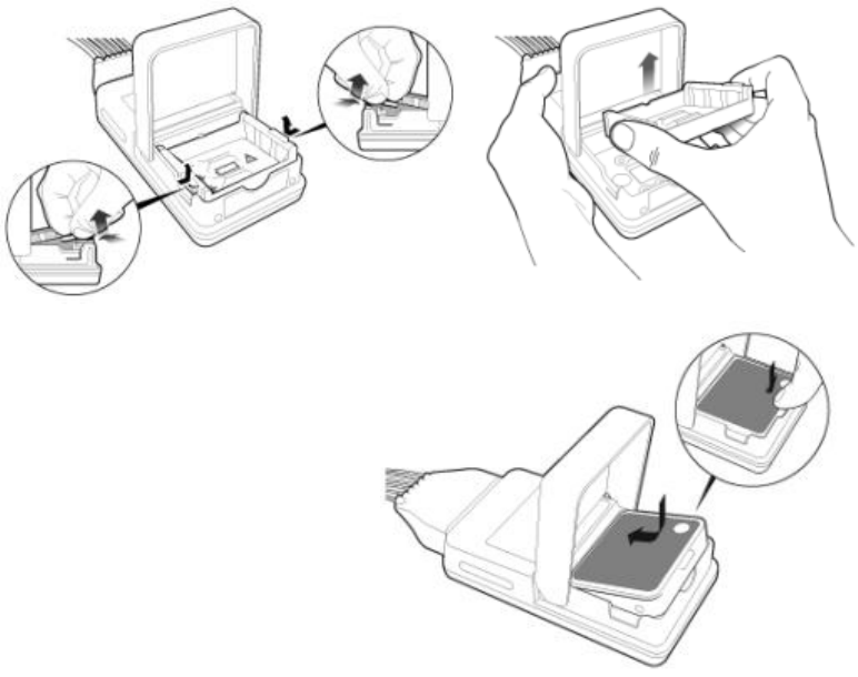
Inserting Batteries
Insert the rechargeable lithium-ion battery using the
following procedure:
Open the battery compartment by lifting up on both bottom sides of the
compartment door.
1 Remove the AA battery tray if present.
2 Insert the battery pack so that the raised tab is aligned with the cutout
in the base of the battery compartment. Close the battery compartment
door.
Draft Copy
Battery Information
4-18 Basic Operation
3 Close the battery compartment door.
4 Watch for the start-up screen on the front of the MX40 to illuminate
briefly.
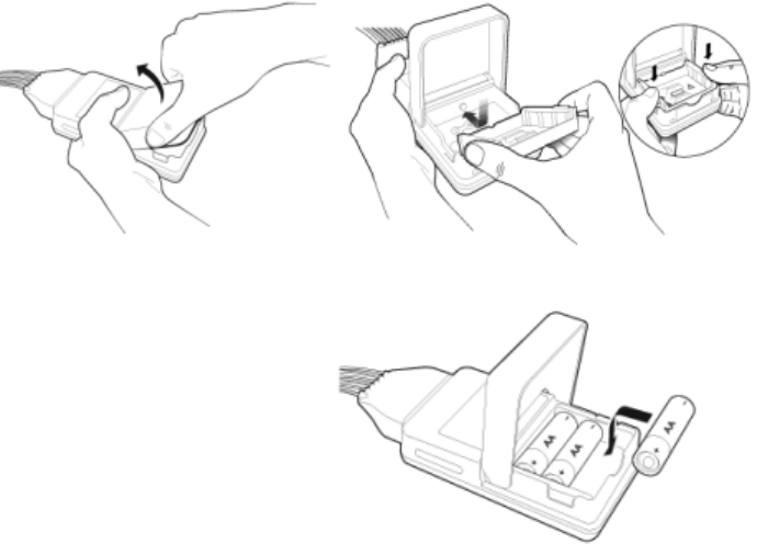
Insert AA batteries into the MX40 using the following
procedure:
1 Open the battery compartment by lifting up on both bottom sides of the
compartment door.
2 Insert the AA battery tray if not already present.
3 Insert three AA 1.5V Alkaline batteries, matching the polarity with the +
indications inside the compartment.
Note—all batteries are inserted with the + polarity in the same direction.
Use of AA batteries is not supported with the WLAN MX40 (Model
Number 865352). Use only the rechargeable lithium-ion battery.
Draft Copy
Battery Information
Basic Operation 4-19
4 Close the battery compartment door.
5 Watch for the start-up screen on the front of the MX40 to illuminate
briefly.
Removing the Batteries
Batteries should be removed when the MX40 is not in use or is being stored.
To remove the batteries, open the battery compartment door and push from
the opening at the bottom of the compartment to pop the batteries out.
Device settings (patient cable type, SpO2 mode, volume, etc.) are retained
when the batteries are removed.
Do not use AA batteries that have different energy levels remaining. Fresh
AA batteries are recommended for each new application.
Important— Do not "store" disposable AA batteries by leaving them in the
incorrect polarity position in the MX40.
Be careful not to short circuit the batteries. Batteries can get hot when
shorted. Short circuits are caused when a piece of metal touches both the
positive and negative terminals simultaneously. More than a momentary
short circuit will generally reduce the battery life. In case of a short circuit,
discard the batteries, or just the shorted one if the batteries are new.
Draft Copy

Battery Information
4-20 Basic Operation
Disposal of Batteries
When disposing of batteries, follow local laws for proper disposal. Dispose
of batteries in approved containers. If local regulations require you to
recycle batteries, recycle batteries in accordance with those regulations.
Battery Charge Status
The battery charge indicator displays in the Status Area and communicates
the remaining battery charge time when using both AA batteries or the
rechargeablelithium-ion battery.
When the MX40 is initially powered-on, it takes approximately 25 seconds
for the indicator to populate. During this time, the indicator displays a ? in
the battery icon.
In order to guarantee overall device performance, certain functionality is
disabled when the battery charge reaches critical levels. See the tables
below for additional information about battery status.
Lithium-ion Rechargeable Battery Charge Status
Approximate
Battery
Life
Remaining
Approximate
Time
Remaining
(ECG only)
Approximate
Time
Remaining
(ECG & Spo2
Continuous)
Functionality
Disabled
Battery
Indicator
LCD
Segments
100%
~ 25 hours
~ 14 hours
None
5 Green
75%
< 19 hours
< 10.5 hours
None
4 Green
50%
< 13 hours
< 7 hours
None
3 Green
25%
< 6 hours
< 3.5 hours
None
2 Green
10%
< 3 hours
< 1.5 hours
None
1 Green
Low battery level
to replace/charge
battery level
< 30 minutes
< 30 minutes
SpO2 and
short-range radio
are disabled.
Display is at half
brightness
1 Red
Red Battery
Icon
Audio
Replace/charge
battery level
< 10 minutes
< 10 minutes
Device shutdown
1 Red
Red Battery
Icon
Draft Copy

Battery Information
Basic Operation 4-21
AA Battery Charge Status
Approximate
Battery
Life
Remaining
Approximate
Time
Remaining
(ECG only)
Approximate
Time
Remaining
(ECG & Spo2
Continuous)
Functionality
Disabled
Battery
Indicator
LCD
Segments
100%
~ 24 hours
~ 9 hours
None
5 Green
75%
< 18 hours
< 7 hours
None
4 Green
50%
< 12 hours
< 5 hours
None
3 Green
25%
< 6 hours
< 2 hours
None
2 Green
10%
< 2 hours
< 1 hours
None
1 Green
Low battery level
to
replace/charge
battery level
< 30 minutes
< 30 minutes
SpO2 and
short-range radio
are disabled.
Display is at half
brightness.
1 Red
Red Battery
Icon
Audio
Replace/charge
battery level
< 10 minutes
< 10 minutes
Device shutdown
1 Red
Red Battery
Icon
Draft Copy

Pouch Use
4-22 Basic Operation
Pouch Use
The MX40 is not intended for direct contact with the patient’s skin. During
normal use, the MX40 should be worn over clothing, in a pocket or,
preferably, in a pouch. The Waterproof Carry Pouch with clear front is an
appropriate means for holding the MX40. See Appendix A, "Accessories"
for ordering information.
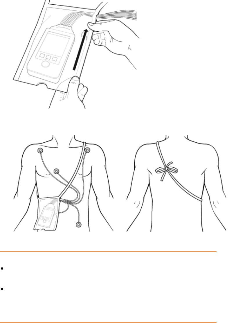
Securing the Pouch
1 See the Carry Pouch, Waterproof, Instructions for Use, P/N 453564267571,
for more information.
2 Insert the MX40 into the pouch with lead wires and SpO2 sensor cable, if
used, exiting from the side opening of the pouch. Pinch the velcro
enclosures together to close the pouch around the cables.
Draft Copy
Pouch Use
Basic Operation 4-23
3 Seal the pouch.
4 Secure the pouch on the patient with the ties around the patient’s
shoulder and under the arm.
5 Check that the patient is comfortable wearing the pouch with the MX40.
Cautions
The pouch is designed to be used exclusively with the MX40. It is not
intended to be used to store patient's personal devices, e.g. cell phones.
Philips recommends that when using a pouch to attach the MX40 to
your patient, consider your patient's condition and be careful about
placement of the straps, as the straps could present a strangulation
hazard.
Draft Copy

Pouch Use
4-24 Basic Operation
Showering
Warning
When the patient is showering, signal quality and leads off detection may
be compromised due to significant movement. Appropriate clinical
precautions must be taken.
Caution
Because the touchscreen display is sensitive to water impact, the display
should be locked when showering.
The MX40 can be used to monitor a patient in the shower, but only when
placed inside a Philips carrying pouch and secured on the patient as
described above. The combination of the MX40 and pouch will withstand
showering for up to 10 minutes.
Drying the MX40 after Showering
After showering, perform the following steps to continue monitoring:
1 Remove the battery.
2 Pat dry the patient cable connections at the electrodes.
3 Wipe the lead wires with care.
4 If wet, dry the outside of the MX40 with a non-lint producing cloth.
5 If wet, wipe dry the inside of the battery compartment. Dry the
batteries.
6 If wet, disconnect the patient cable and shake out any water. Dry the
connector pin area with a cotton swab.
7 Re-insert the battery.
Caution
The MX40 should not be used for monitoring if the battery compartment is
wet. Remove the batteries and wipe the compartment dry before continued
monitoring use.
Draft Copy
Pouch Use
Basic Operation 4-25
Accidental Liquid Exposure
If the MX40 is accidentally immersed in liquid, no damage to the device
and no electrical safety issues for the patient will result. Remove the device,
dry it off, and follow the procedure for cleaning/sterilization under
"Cleaning and Sterilization" as needed.
Draft Copy

Telemetry Mode Use
4-26 Basic Operation
Telemetry Mode Use
To minimize patient disruption, the MX40 operates in Telemetry Mode
when connected to the Information Center. In Telemetry Mode, the local
volume is set to zero and the display is off. You can activate the display at
any time by touching the Main Screen button for two seconds. All active
alarms can be viewed when the display is on, however audible alarm
indicators are not annunciated. Regardless of the display status, all
measurement data is being sent to the Information Center. Telemetry Mode
is only available when connected to the Information Center.
Draft Copy

Monitoring Mode Use
Basic Operation 4-27
Monitoring Mode Use
You may find the use of Monitoring Mode helpful when spending extended
time directly with your patient, e.g. during transport, showering, dressing
change. The display is always on for easy viewing and should an alarm
condition occur, it will be announced locally at the MX40 and at the
Information Center if networked connected. If the MX40 is not network
connected, the alarm is only announced locally.
To use Monitor Mode:
1 Press the SmartKeys Button.
2 Press the Mode: Telemetry / Mode: Monitor SmartKey and choose
Mode: Monitor.
Draft Copy

Briefing the Patient
4-28 Basic Operation
Briefing the Patient
Warning
Patients should be instructed not to interact with the display of the device
and to not open the battery compartment while the MX40 is in use.
Note — Pausing alarms at the Information Center activates the MX40
display. Patients should be notified that this is normal operation and not
cause for any concern.
If the Multi-Function button has been configured to generate a Nurse Call
alarm, recording at the Information Center, or both, instruct the patient to
use the button when needed.
If desired, you can turn off patient use of the Multi-Function button at the
Information Center. For more information see Patient Configurable Settings
in Telemetry Setup p. 11-10.
Draft Copy
Alarms 5-1
5. Alarms
The section provides alarm information that applies to all measurements.
Measurement-specific alarm information is discussed in the sections on
individual measurements.
Alarms Overview ...................................................................................... 5-2
Physiologic Alarms ................................................................................. 5-10
Technical Alarms (INOPs) ..................................................................... 5-14
Draft Copy

Alarms Overview
5-2 Alarms
Alarms Overview
The MX40 has two different types of alarms: physiological alarms and
INOPs. For MX40 devices operating with IntelliVue Information Center
Release L and M, physiological alarms are not available locally on the
MX40. INOPs are displayed as described here.
For MX40 devices operating with IntelliVue Information Center Release N
or IntelliVue Information Center iX, physiological alarms are available
locally on the MX40 regardless of network connection to the Information
Center. Alarm settings are as configured by the Information Center.
Changes to physiological alarm settings can only be made at the
Information Center. Audible alarm indicators are annunciated only when
operating in Monitor Mode or when the MX40 is not networked connected.
Physiological Alarms
Physiological alarms are red and yellow alarms. A red alarm indicates a
high priority patient alarm such as a potentially life threatening situation
(for example, asystole). A yellow alarm indicates a lower priority patient
alarm (for example, a low SpO2 alarm limit violation). Additionally there
are short yellow alarms, most of which are specific to arrhythmia-related
patient conditions (for example, ventricular bigeminy).
INOPs
INOPs are technical alarms, they indicate that the monitor cannot measure
or detect alarm conditions reliably. If an INOP interrupts monitoring and
alarm detection (for example, LEADS OFF), the monitor places a question
mark in place of the measurement numeric and an audible indicator tone
will be sounded. INOPs without this audible indicator indicate that there
may be a problem with the reliability of the data, but that monitoring is not
interrupted.
Most INOPs are light blue, however there are a small number of INOPs
which are always yellow or red to indicate a severity corresponding to red
and yellow alarms. The following INOPs can also be configured as red or
yellow INOPs to provide a severity indication:
ECG LEADS OFF
REPLACE BATTERY (when using disposable batteries)
TELE BATT EMPTY (when using the rechargeable battery pack)
All monitors in a unit should have the same severity configured for these
INOPs.
Draft Copy

Alarms Overview
Alarms 5-3
The MX40 is designed to achieve visual alarm notification at a distance of
up to one meter, which is consistent with its intended use model as a
wearable monitor.
Alarms are indicated after the alarm delay time. This is made up of the
system delay time plus the trigger delay time for the individual
measurement. For more information see ECG Performance
Disclosure/Specifications p. 15-27 .
A downward facing arrow symbol next to the alarm message informs you
that more than one message is active and the messages rotate every three
seconds. The monitor sounds an audible indicator for the highest priority
alarm.
Visual Alarm Indicators
Warning
The MX40 display is inactive for a majority of the time because it is
operating in Telemetry Mode. You must activate the screen to view or hear
any alarms at the MX40. Upon activating the screen, the alarm volume may
be set to zero if desired.
Alarm Message
An alarm message text appears in the alarm status area at the top of the
screen indicating the source of the alarm. The background color of the
alarm message matches the alarm priority: red for red alarms, yellow for
yellow alarms, light blue for standard INOPs, red for red INOPs and yellow
for yellow INOPs. The asterisk symbols (*) beside the alarm message match
the alarm priority: *** for red alarms, ** for yellow alarms, * for short yellow
alarms. Standard INOPs do not have a symbol, red and yellow INOPs have
exclamation marks beside the alarm message: !!! for red INOPs and !! for
yellow INOPs. If more than one alarm is present, there is a downward
facing arrow symbol at the right side and the active alarm/inop messages
rotate every three seconds.
Alarm limit violation messages are displayed in text form, for example **
SpO2 LOW.
Draft Copy
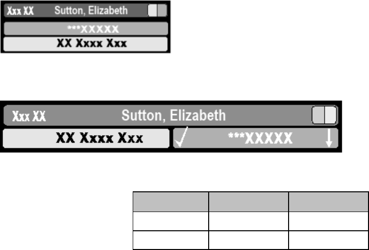
Alarms Overview
5-4 Alarms
Alarm Indicator
An Alarm Indicator on the MX40 main display communicates alarm/INOP
conditions that have not been acknowledged. The alarm indicator is
divided into two sections and appears in the upper right hand corner
normally occupied by the time display. The right section flashes for a
physiological alarm, except for short yellow alarms where the indicator will
light for approximately six seconds. The color is yellow or red
corresponding to the highest priority alarm currently present.
An unacknowledged physiological alarm and INOP appears as (portrait
view):
An acknowledged physiological alarm and INOP with an additional
unacknowledged physiological alarm appears as (landscape view):
The left section lights continuously for a standard INOP and flashes for
INOPs configured as red or yellow alarms as follows:
INOP Color
On
Off
Yellow
1.0 seconds
1.0 seconds
Red
0.25 seconds
0.25 seconds
If only physiological alarms are present, and no INOPs, the physiological
alarms will use both left and right sections to flash (for red and yellow
alarms) or light for approximately six seconds (for short yellow alarms). If
only INOPs are present, and no physiological alarms, red and yellow
INOPs will use both left and right sections to flash, but standard INOPs will
always light continuously in the left section only.
Once all alarm/INOP conditions are acknowledged, the time display
reappears.
Flashing Numeric
The numeric of the measurement in alarm flashes.
Draft Copy

Alarms Overview
Alarms 5-5
Audible Alarm Indicators when in Monitoring Mode
The audible alarm indicators configured for your monitor depend on which
alarm standard applies in your hospital. Audible alarm indicator patterns
are repeated until you acknowledge the alarm by switching it off or
pausing it, or until the alarm condition ceases (if audible alarm indication is
set to non-latching).
Warning
Do not rely exclusively on the audible alarm system for patient
monitoring. Adjustment of alarm volume to a low level or off during
patient monitoring may result in patient danger. Remember that the
most reliable method of patient monitoring combines close personal
surveillance with correct operation of monitoring equipment.
No audible alarm indicators are available when the MX40's volume
setting is zero or when operating in Telemetry Mode. Audible alarm
indicators become active as soon as the MX40 is no longer connected to
the Information Center.
Traditional Audible Alarms (HP/Agilent/Philips/Carenet)
Red alarms and red INOPs: A high pitched sound is repeated once a
second.
Two-star yellow alarms and yellow INOPs: A lower pitched sound is
repeated every two seconds.
One-star yellow alarms (short yellow alarms): The audible indicator is
the same as for yellow alarms, but of shorter duration.
Standard INOPs: an INOP tone is repeated every two seconds.
ISO/IEC Standard Audible Alarms
Red alarms and red INOPs: A high pitched tone is repeated five times,
followed by a pause.
Two-star yellow alarms and yellow INOPs: A lower pitched tone is
repeated three times, followed by a pause.
One-star yellow alarms (short yellow alarms): The audible indicator is
the same as for yellow alarms, but of shorter duration.
Standard INOPs: a lower pitched tone is repeated twice, followed by a
pause.
Draft Copy

Alarms Overview
5-6 Alarms
Acknowledging Alarms
To acknowledge all active physiological alarms and INOPs, touch the
Silence Alarm button. This switches off the audible alarm indicators, if
present, and alarm messages at the MX40 and at the IntelliVue Information
Center iX.
A check mark beside the alarm message indicates that the alarm has been
acknowledged .
If the condition that triggered the alarm is still present after the alarm has
been acknowledged, the alarm message stays on the screen with a check
mark symbol beside it, except for NBP alarms and alarms from other
intermittent measurements. When such an alarm is acknowledged the
alarm message disappears.
If the alarm condition is no longer present, all alarm indicators stop and the
alarm is reset.
Switching off the alarms for the measurement in alarm, or switching off the
measurement itself, also stops alarm indication.
Pausing or Switching Off Alarms
If you want to temporarily prevent alarms from sounding, for example
while you are moving a patient, you can pause alarms, if configured.
Depending on your MX40 configuration, alarms are paused for one, two or
three minutes.
Cautions
When operating with Information Center Release L or M, the alarm
pause time of the MX40 is not configurable. The alarm pause time for
the MX40 is always two minutes.
When operating with Information Center Release L or M, if alarms are
paused at the Information Center, the "Alarms Paused" message is only
displayed at the Information Center.
To Pause All Alarms
Select the Alarms SmartKey and select Pause Alarms. A timer on the
display shows the remaining pause time.
Draft Copy

Alarms Overview
Alarms 5-7
While Alarms are Paused
In the alarm field, the MX40 displays the message ALARMS PAUSED
1:28 or ALARMS OFF, together with the alarms paused symbol or the
alarms off symbol.
No alarms are sounded and no alarm messages are shown.
INOP messages are shown but no INOP tones are sounded.
The only exceptions are the INOPs CUFF NOT DEFLATED, NBP CUFF
OVERPRESS and INOPs relating to empty, missing and malfunctioning
batteries.
These INOPs switch the alarms on, and the INOP tones are sounded,
even if alarms are paused or off. You need to remove the INOP
condition first before you can switch the alarm tones off again.
Warning
If connection to the Information Center is lost during an alarms paused
period, upon reconnection, alarms remain paused at the Information Center
for the set time. You can resume alarms from the Patient Window at the
Information Center at any time.
Restarting Paused Alarms
To manually switch on alarm indication again after a pause, select Pause
Alarms.
Alarm Limits
The alarm limits you set determine the conditions that trigger yellow and
red limit alarms. For some measurements (for example, SpO2), where
setting the high alarm limit to the maximum of 100 switches the high alarm
off, or setting the low alarm limit to the minimum of 0 switches it off. In
these cases, the alarms off symbol is not displayed.
Warning
Be aware that the monitors in your care area may each have different alarm
settings, to suit different patients. Always check that the alarm settings are
appropriate for your patient before you start monitoring.
Draft Copy

Alarms Overview
5-8 Alarms
Viewing Individual Alarm Limits
You can see the alarm limits set for each measurement next to the
measurement numeric on the main screen.
Reviewing Alarms
You can see which alarms and INOPs are currently active in the respective
alarms and INOPs fields at the top of the screen.
To see the currently active alarms and INOPs listed in one place, touch the
Alarms area.
All alarms and INOPs are erased from the Alarm Messages window when
you discharge a patient, or if you change to Demonstration Mode.
Review Alarms Window
The Review Alarms window contains a list of the 50 most recent alarms and
INOPs with date and time information.
The Review Alarms window also shows when alarms are paused or
silenced.
Note — Alarms that occur during an alarm suspend period will appear in
the Review Alarm window, however, they are not communicated to the
Information Center.
Alarm Reminders
The MX40 provides alarm reminders when operating with IIC Release N or
IIC iX. The reminder time period is selected at the Information Center.
For Information Center Release L/M, reminders are only available for
INOPs.
Draft Copy

Alarms Overview
Alarms 5-9
Latching Alarms
The alarm latching setting for your MX40 defines how the alarm indicators
behave when you do not acknowledge them. When alarms are set to
non-latching, their indicators end when the alarm condition ends.
Switching alarm latching on means that visual and/or audible alarm
indications are still displayed or announced by the monitor after the alarm
condition ends. The indication lasts until you acknowledge the alarm by
touching the Alarm Silence button.
Alarm Latching Behavior
Red & Yellow Measurement Alarms
Non-latching
Alarms
Visual and
Audible
Latching
Alarm has not been
acknowledged.
Alarm condition still
present.
Alarm tone on. Alarm
message. Flashing
numerics.
Alarm tone on. Alarm
message. Flashing
numerics.
Alarm condition no
longer present.
All audible and visual
alarm indicators
automatically stop.
Alarm tone on. Alarm
message . Flashing
numerics.
Alarm has been
acknowledged.
Alarm condition still
present.
Alarm tone off. Alarm
message with check
mark. Flashing
numerics. Audible
alarm reminder (if
configured)
Alarm tone off. Alarm
message with check
mark. Flashing
numerics. Audible
alarm reminder (if
configured)
Alarm condition no
longer present.
Audible and visual
alarm indicators
automatically stop.
Audible and visual
alarm indicators
automatically stop.
Alarm Behavior at Power On
If the MX40 is powered off for longer than one minute and then powered
on again (or after a loss of power lasting longer than one minute, or when a
patient is discharged), the device restores the latest alarm settings from
the Information Center.
If battery power is lost for less than one minute, the alarm on/off condition
prior to the power loss is restored.
Draft Copy

Physiologic Alarms
5-10 Alarms
Physiologic Alarms
Physiologic alarms indicate a life-threatening situation or a less urgent
situation such as heart rate beyond limits.
Warning
Do not rely exclusively on the audible alarm system for patient
monitoring. Adjustment of alarm volume to a low level during patient
monitoring may result in patient danger. Remember that the most
reliable method of patient monitoring combines close personal
surveillance with correct operation of monitoring equipment.
Arrhythmia alarm chaining and customizing arrhythmia alarm settings are
described in the ECG and Arrhythmia Monitoring chapter. There are two
levels of arrhythmia analysis available: Basic and Enhanced. Enhanced
analysis includes Basic alarms.
The MX40 provides physiological alarms based on the settings at the
Information Center Release N or IntelliVue Information Center iX.
Alarming is not active on the MX40 until it is configured via an active
association with the Information Center.
In the following table, Red (***) alarms are listed alphabetically, followed by
the Yellow (**) alarms, and the Yellow (*) alarms.
Note — The physiological alarm messages displayed on the MX40 use a
short text format. Alarm messages displayed at the Information Center use
and extended text format, e.g. "*HR yyy<xxx".
Alarm Text
Priority
Condition
Source
*** APNEA
Note — Only available with
IIC iX.
Red
Respiration has stopped for longer than
the preset apnea time.
RESP
*** ASYSTOLE
Red
Asystole.
No QRS for 4 consecutive seconds
ST/AR Basic
& Enhanced
Arrhythmia
*** EXTREME BRADY
Red
Extreme Bradycardia.
Heart Rate (yyy) less than Extreme Brady
limit (xxx)
ST/AR Basic
& Enhanced
Arrhythmia
*** DESAT
Red
Very Low SpO2 Saturation.
SpO2 value below Desaturation limit
Note— Desat limit is set 10 points below
low limit with IIC Release N. It is
configurable with IIC iX.
SpO2
Draft Copy

Physiologic Alarms
Alarms 5-11
Alarm Text
Priority
Condition
Source
***EXTREME TACHY
Red
Extreme Tachycardia.
Heart Rate (yyy) greater than Extreme
Tachy limit
ST/AR Basic
& Enhanced
Arrhythmia
*** VENT FIB/TACH
Red
Ventricular Fibrillation.
Fibrillatory wave (sinusoidal wave
between 2-10 Hz) for 4 consecutive
seconds
ST/AR Basic
& Enhanced
Arrhythmia
*** V-TACH
Red
Ventricular Tachycardia.
Consecutive PVCs greater than or equal
to V-Tach Run limit and Heart Rate
greater than V-Tach limit (xxx)
ST/AR Basic
& Enhanced
Arrhythmia
** dQTc
Yellow
dQTC value has exceeded the dQTC high
limit for > 5 minutes for 2 consecutive time
periods.
ECG/QT
** MULTI ST
Yellow
Two contiguous ST leads have values
exceeding elevation or depression alarm
limits for > 60 sec.
ECG/ST
** NBP High
Yellow
High limit has been exceeded for high
pressure limit.
NBP
** NBP Low
Yellow
Low limit has been exceeded for low
pressure limit.
NBP
** QTc High
Yellow
QTc value has exceeded the QTc high
limit for > 5 minute for2 consecutive time
periods.
ECG/QT
** RR HIGH
Note — Only available with
IIC iX.
Yellow
The respiration rate has exceeded the
high alarm limit.
RESP
** RR LOW
Note — Only available with
IIC iX.
Yellow
The respiration rate has dropped below
the low alarm limit.
RESP
**SpO2T HIGH
Yellow
High SpO2.
SpO2 value (yyy) greater than high SpO2
limit (xxx)
SpO2
** SpO2T LOW
Yellow
Low SpO2.
SpO2 value (yyy) less than low SpO2 limit
(xxx).
SpO2
** ST-LEAD HIGH
Yellow
ST segment is elevated.
ECG/ST
** ST-LEAD LOW
Yellow
ST segment is depressed.
ECG/ST
** ST ELEV
Yellow
Two contiguous leads have ST values
exceeding the STEMI limits.
ECG/ST
*/**AFIB
Yellow
Atrial fibrillation waveform detected.
ST/AR
Enhanced
Arrhythmia
Draft Copy

Physiologic Alarms
5-12 Alarms
Alarm Text
Priority
Condition
Source
*/** HR High
Yellow
Heart Rate (yyy) greater than the upper
Heart rate limit (xxx).
ST/AR Basic
& Enhanced
Arrhythmia
*/** HR Low
Yellow
Heart Rate (yyy) lower than the lower
Heart Rate limit (xxx).
ST/AR Basic
& Enhanced
Arrhythmia
*/** IRREGULAR HR
Yellow
Consistently irregular rhythm (irregular
R-R intervals).
ST/AR
Enhanced
Arrhythmia
* MISSED BEAT
Yellow
No beat detected for 1.75 x average R-R
interval for Heart Rate greater than 120, or
no beat for 1 second with Heart Rate
greater than 120 (non-paced patient only).
ST/AR
Enhanced
Arrhythmia
* MULTIFORM PVCs
Yellow
The occurrence of two differently shaped
Vs, each occurring at least twice within the
last 300 beats as well as each occurring at
least once within the last 60 beats.
ST/AR
Enhanced
Arrhythmia
* NON-SUSTAIN VT
Yellow
A run of Vs having a ventricular Heart
Rate greater than V-Tach limit but lasting
for less than the V-Tach Run limit.
ST/AR
Enhanced
Arrhythmia
*Nurse Call
Yellow
The patient has pressed the
Multi-Function Button on the MX40.
* PACER NOT CAPTURE
Yellow
No QRS for 1.75 x the average R-R
interval with Pace Pulse (paced patient
only).
ST/AR Basic
& Enhanced
Arrhythmia
* PACER NOT PACING
Yellow
No QRS and Pace Pulse for 1.75 x the
average R-R interval (paced patient only).
ST/AR Basic
& Enhanced
Arrhythmia
* PAIR PVCs
Yellow
Two consecutive PVCs between
non-PVCs.
ST/AR
Enhanced
Arrhythmia
* PAUSE
Yellow
No QRS detected for x seconds. Choices
of >1.5 to 2.5 seconds.
ST/AR
Enhanced
Arrhythmia
* PVCs /MIN HIGH
Yellow
PVCs within one minute exceed by the
PVCs/min limit (xxx).
ST/AR Basic
& Enhanced
Arrhythmia
Draft Copy

Physiologic Alarms
Alarms 5-13
Alarm Text
Priority
Condition
Source
* R-ON-T PVCs
Yellow
For Heart Rate less than 100, a PVC with
R-R interval less than 1/3 the average
interval followed by a compensatory pause
of 1.25 x average R-R interval, or 2 such
Vs without a compensatory pause
occurring within 5 minutes of each other.
(When Heart Rate is greater than 100, 1/3
R-R interval is too short for detection.)
ST/AR
Enhanced
Arrhythmia
* RUN PVCs
Yellow
Run of PVCs greater than or equal to 2.
ST/AR
Enhanced
Arrhythmia
* SVT
Yellow
Run of SVPBs greater than or equal to
SVT Run limit and with SVT Heart Rate
greater than the SVT Heart Rate limit.
ST/AR
Enhanced
Arrhythmia
* VENT BIGEMINY
Yellow
A dominant rhythm of N, V, N, V (where
N= supraventricular beat, V=ventricular
beat).
ST/AR
Enhanced
Arrhythmia
* VENT RHYTHM
Yellow
A dominant rhythm of adjacent Vs greater
than Vent Rhythm limit and ventricular
Heart Rate less than V-Tach limit.
ST/AR
Enhanced
Arrhythmia
* VENT TRIGEMINY
Yellow
A dominant rhythm of N, N, V, N, N, V
(where N=supraventricular beat,
V=ventricular beat).
ST/AR
Enhanced
Arrhythmia
Draft Copy

Technical Alarms (INOPs)
5-14 Alarms
Technical Alarms (INOPs)
Technical Alarms, or INOPs (inoperative conditions), are sourced at the
MX40, the ST/AR algorithm running at the Information Center, or the
IntelliVue Patient Monitor. They identify inoperative conditions (that is
conditions where the system is not operating properly and therefore cannot
measure or detect alarm conditions reliably). There are four levels of
Technical Alarms:
Severe - Monitoring and alarm generation are disabled. Visual alarm
indicator on the MX40. Audible tone at the Information Center. Must be
acknowledged by a clinician.
Hard - Monitoring and alarm generation are disabled. Visual alarm
indicator on the MX40. Audible tone at the Information Center.
If the hard INOP is "latched", the sound will be silenced, but the
message will remain on the display until resolution of the offending
condition.
Soft - Monitoring and alarms remain active. Visual alarm indicator on
the MX40 and at the Information Center. No audible tones are
generated at the Information Center
Red/Yellow - Replace Battery and ECG Leads Off INOPs may be
configured to display as either Red or Yellow Technical Alarms.
Note - The ECG Leads Off INOP will initially display as a cyan
technical alarm until a valid ECG signal is obtained.
In the following table, technical alarms are listed alphabetically.
Alarm Text
Priority
Condition
What to do
BATTERY LOW T
Source - MX40
Soft
There is less than 15
minutes of monitoring
time remaining (AA
batteries).
Lithium-ion battery level
is < 10% or has <30
minutes remaining time.
Replace batteries promptly to
avoid shutdown and cessation
of monitoring.
Insert a charged lithium-ion
battery pack.
CANNOT ANALYZE ECG
Source - MX40 (IIC iX
only) and Information
Center
Hard
Arrhythmia algorithm
cannot reliably analyze the
ECG data on any
monitored leads.
Assess the lead selections,
initiate relearn, and validate
analyzed rhythm. Check other
INOPs for possible source of
problem.
Draft Copy

Technical Alarms (INOPs)
Alarms 5-15
Alarm Text
Priority
Condition
What to do
CHECK PAIRING
Source - MX40
Yellow
Technical
Alarm
There is a problem with
device pairing.
When the MX40 is
wirelessly paired with an
X2 patient monitor (no
label) docked with a
larger networked MP
series monitor, and the
network connection is
lost.
Check that the bedside
monitor or cableless
measurement device is
correctly paired.
Select the correct device to be
paired.
cl NBP Batt Low
Source - Cableless
Measurement Device
Hard
CL NBP Pod weak battery
condition.
Charge CL NBP Pod.
cl NBP Batt Empty
Source - Cableless
Measurement Device
Severe
CL NBP Pod empty battery
condition. Monitoring is not
possible.
Replace CL NBP Pod.
Recharge depleted CL NBP
Pod.
cl NBP DISCONNECT
Source - Cableless
Measurement Device
Hard
CL NBP Pod is not
connected with the MX40.
Resolve interference
condition.
Reduce range between CL
NBP Pod and MX40.
cl SpO2 Batt Low
Source - Cableless
Measurement Device
Hard
CL SpO2 Pod weak battery
condition.
Charge CL SpO2 Pod.
cl SpO2 Batt Empty
Source - Cableless
Measurement Device
Severe
CL SpO2 Pod empty
battery condition.
Monitoring is not possible.
Replace CL SpO2 Pod.
Recharge depleted SpO2 Pod.
cl SpO2 DISCONNECT
Source - Cableless
Measurement Device
Hard
CL SpO2 Pod is not
connected with the MX40.
Resolve interference
condition.
Reduce range between CL
SpO2 Pod and MX40.
!!!/!! CUFF NOT
DEFLATED
Source - Cableless
Measurement Device
Severe
Cuff pressure has
exceeded the specified
safety limit.
Remove cuff and tubing and
expel air.
!!!/!! CUFF OVERPRESS
Source - Cableless
Measurement Device
Severe
Cuff pressure has
increased above
overpressure safety limits.
Remove cuff and tubing and
expel air.
Draft Copy

Technical Alarms (INOPs)
5-16 Alarms
Alarm Text
Priority
Condition
What to do
ECG/ARRH ALARM(S)
OFF
Source - MX40
Soft
ECG is turned off.
Turn on ECG.
ECG LEADS OFF
Note This INOP may also
be configured to display as
a Red or Yellow Technical
Alarm.
Source - MX40
Red or
Yellow or
Hard
Technical
Alarm
Multiple leads are off.
Re-attach ECG leads to patient..
<electrode> LEAD OFF
Source - MX40
Hard
Single lead is off.
If primary lead is MCL,
lead will be identified as
V/C in INOP text.
Re-attach ECG leads to patient.
LEADSET UNPLUGGED
Source - MX40
Hard
Patient cable has been
unplugged from the
MX40.
Incompatible leadset
attached to patient cable.
Re-attach the patient cable.
Replace the leadset.
LEADSET LIFE
Soft
The single-patient use
leadset has exceeded its
limit of 25 cycles.
Replace with new leadset.
LOCAL AUDIO OFF
Source - MX40
Note — This is normal
operation in Telemetry
Mode.
Soft
There is no alarm audio
notification when operating
in Telemetry Mode.
Change to Monitor Mode.
NBP INTERRUPTED
Source - Cableless
Measurement Device
Hard
The preset maximum time
for the total measurement
has been exceeded.
Reduce patient movement and
avoid interaction with the cuff
and tubing.
NBP MEASURE FAILED
Source - Cableless
Measurement Device
Hard
Measurement values
cannot be derived.
Attach cuff to new location on
patient.
Replace cuff.
Draft Copy

Technical Alarms (INOPs)
Alarms 5-17
Alarm Text
Priority
Condition
What to do
NBP EQUIP MALF
Source - Cableless
Measurement Device
Hard
Tubing may be
obstructed or kinked.
Hardware malfunction.
Check tubing.
If condition persists, contact
Service.
NO ALARM DISPLAY
Source - MX40
Soft
When operating with
Information Center
Release L Or M, there is
no local alarming at the
MX40, networked or
non-networked.
Condition is not present when
operating with Information
Center Release N or later
(unless specifically configured to
operate in this way).
NO CENTRAL MONITOR
(appears at MX40 only)
Source - MX40
Hard
The MX40 is out of
range of the network.
Patient Sector at the
Information Center is in
Standby.
Return the MX40 to the
coverage area.
Select Resume at the
Information Center.
NO HOST MONITOR
Source - MX40
Hard
The paired MX40/bedside
monitor is out of
short-range radio range or
there is excessive radio
interference.
Reduce the distance between
the devices.
Identify and remove
interference source.
NO SIGNAL
(appears at the Information
Center only)
Note — When operating
with IIC iX, the INOP will
display as NO DATA PWM.
Source - Information
Center
Hard,
Latched
The MX40 is outside the
coverage area, or
No batteries in the
MX40, or
The MX40 has failed.
Make sure that the MX40 is
within the coverage area and
has good batteries.
Replace the MX40 if Power
On Self Test fails.
Put bed in Standby.
Contact Service
REPLACE BATTERY T
Source - MX40
Note — This INOP may
also be configured to
display as a Red or Yellow
Technical Alarm.
Red or
Yellow or
Hard
Technical
Alarm,
Latched
Dead battery. No
monitoring is occurring.
Replace batteries.
RESP EQUIP MALF
Source - MX40
Hard
Malfunction in the Resp
equipment.
MX40 requires
calibration.
Contact Service.
RESP LEAD OFF
Note — OR leadsets
cannot be used to monitor
Resp with the MX40.
Source - MX40
Hard
Resp lead off.
Re-attach lead to patient.
Draft Copy

Technical Alarms (INOPs)
5-18 Alarms
Alarm Text
Priority
Condition
What to do
SOME ECG ALARMS OFF
Soft
Some ECG alarms have
been turned off at the
Information Center.
For information only.
SpO2T EQUIP MALF
Source - MX40
Hard
Malfunction in the SpO2
equipment
Contact Service.
SpO2T ERRATIC
Source - MX40
Hard
Erratic SpO2
measurements, often due
to a faulty sensor or invalid
SpO2 measurements, or
incorrect transducer
position
Repeat measurement, reposition
sensor on patient, or finally,
replace sensor.
SpO2T EXTD UPDATE
Numeric is replaced by a
-?-.
Source - MX40
Soft
The update period of
displayed values is
extended due to an NBP
measurement on the same
limb or an excessively
noisy signal.
If NBP is not active, check the
sensor placement. Reposition
the sensor on patient, or replace
sensor.
SpO2T LOW PERF
Source - Monitor
Soft
Accuracy may be reduced
due to low perfusion. Data
displayed with ?.
Increase perfusion. Change
sensor site. Avoid site distal to
BP cuff or intra-arterial line.
Warm the site.
SpO2T INTERFERENCE
Source - MX40
Hard
Level of ambient light or
level of electrical
interference are so high
that the SpO2 sensor
cannot measure SpO2 and
pulse rate.
Reduce ambient light to sensor
or electrical noise sources.
SpO2T NO SENSOR
Note — Silencing this
technical alarm turns off the
SpO2 measurement on the
MX40 and at the
Information Center.
Source - MX40
Hard
No sensor attached to
SpO2 device.
Attach SpO2 sensor.
%SpO2T NOISY SIGN
Source - MX40
Hard
Excessive patient
movements or electrical
interference are causing
irregular pulse patterns
Reduce movement or electrical
noise sources.
SpO2T NO PULSE
Source - MX40
Note — When paired
directly with an IntelliVue
MP5 Patient Monitor, the
INOP will display as SpO2T
SENSOR OFF.
Hard
Pulse is too weak or not
detectable
Sensor has fallen off at
patient.
Check connection to patient.
Change sensor site. Avoid site
distal to BP cuff or
intra-arterial line.
Draft Copy

Technical Alarms (INOPs)
Alarms 5-19
Alarm Text
Priority
Condition
What to do
SpO2 POOR SIGNAL
Source - MX40
Soft
Although a measurement
may be possible, its
accuracy may be reduced
due to poor signal quality.
Apply the sensor according to
the manufacturer's
instructions.
Relocate the sensor to a
different site on the patient.
SpO2T SEARCHING
Source - MX40
Soft
The patient signal is
analyzed, but a valid
numeric is not available
yet.
Wait for the measurement to
complete.
SpO2T SENSOR OFF
Note — The ability of the
algorithm to detect this
condition depends on the
sensor type in use.
Hard
The algorithm has
determined that a sensor is
connected, but not properly
applied to the patient.
Apply the sensor according to
the manufacturer's
instructions.
If the condition persists,
relocate the sensor to a
different site on the patient.
SpO2T SENSOR MALF
Source - MX40
Hard
Malfunction of the SpO2
sensor/adapter cable
Replace sensor.
SpO2 UNKN SENSOR
Source - MX40
Hard
The connected SpO2
sensor and/or adapter
cable is not supported by
the hardware version.
Use specified sensor and/or
adapter cable.
SpO2T UPGRADE
Source - MX40
Soft
SpO2 hardware is in
upgrade process.
Monitoring is not possible.
Wait for the upgrade process to
complete.
TELE BATT EMPTY
Note — This INOP may
also be configured to
display as a Red or Yellow
Technical Alarm.
Source - MX40
Note — For Information
Center Release L or M, this
INOP will appear as
"REPLACE BATTERY T".
Hard,
Latched
Lithium-ion battery level is
critically low. A 10-minute
countdown begins. The
MX40 will shut down if the
condition is not cleared.
Insert a charged lithium-ion
battery pack.
TELE BATTERY TEMP
Source - MX40
Note — For Information
Center Release L or M, this
INOP will appear as
"REPLACE BATTERY T"
Hard
The temperature of the
lithium-ion battery is above
55o C or below -5o C.
Replace the lithium-ion battery.
TELE CHECK BATT
Source - MX40
Soft
Lithium-ion battery has <
25 charge cycles
remaining before reaching
the charge cycle maximum
limit.
Be aware that the Lithium-ion
battery pack will soon need
replacement.
Draft Copy

Technical Alarms (INOPs)
5-20 Alarms
Alarm Text
Priority
Condition
What to do
TELE MALFUNCTION
Source - MX40
Hard
MX40 malfunction or
self-test failure.
Contact Service to replace the
MX40.
TELE REMOVE BATT
Source - MX40
Note — For Information
Center Release L or M, this
INOP will appear as
"REPLACE BATTERY T".
Hard,
Latched
The temperature of the
lithium-ion battery is >60o
C and the battery must be
removed.
Replace the lithium-ion
battery.
Dispose of old battery
properly.
TELE SERVICE BATT
Source - MX40
Hard
The lithium-ion battery has
exceeded the maximum
charge cycle limit and
reached the end of its
useful life.
Replace the lithium-ion
battery.
Dispose of old battery
properly.
TELE WEAK SIGNAL
Source - MX40
Soft
Patient is at outer range
of the radio coverage
area.
The MX40 is receiving a
weak signal with high
data loss from the AP.
Condition exists for
multiple devices in a
specific area
Return patient to the coverage
area.
If patient is in close proximity
to AP, replace the MX40.
Contact service.
The AP covering the specific
area is suspect. Contact
Service
TRANSMITTER OFF
Source - MX40
Hard
RF Auto Shutoff after 10
minutes of all leads off and
no SpO2 sensor
connected.
Reattach ECG leads to
patient.
Reattach SpO2 sensor.
UNSUPPORTED LAN
Source - MX40
Hard
The MX40 (WLAN) is
connected to the Access
Point, but cannot obtain an
IP address.
Correct the IP address issue.
WIFI OUT OF RANGE
Source - MX40
Hard
The MX40 (WLAN) is out
of range of an access
point.
Correct the RF coverage issue.
Draft Copy
ECG and Arrhythmia Monitoring 6-1
6. ECG and Arrhythmia
Monitoring
This section covers the specifics of ECG measurement and the ST/AR
Arrhythmia, ST, and QT algorithms used for arrhythmia monitoring.
ECG Safety Information ........................................................................... 6-2
Measuring ECG ......................................................................................... 6-5
Connecting and Positioning ECG Electrodes ........................................ 6-6
Selecting the Primary and Secondary ECG Leads ................................ 6-8
Checking Paced Status .............................................................................. 6-9
Understanding the ECG Display........................................................... 6-10
Monitoring Paced Patients ..................................................................... 6-11
Changing the Size of the ECG Wave .................................................... 6-12
Choosing EASI or Standard Lead Placement ...................................... 6-13
Derived 12-lead ECG .............................................................................. 6-14
ECG Configuration .................................................................................. 6-15
ECG Leads Monitored ............................................................................ 6-16
Reconstructed Leads ............................................................................... 6-18
Chest Electrode Placement ..................................................................... 6-19
3-Wire Placement ..................................................................................... 6-20
5-Wire Placement (Standard Mode)...................................................... 6-21
5-Wire Placement (EASI Mode) ............................................................. 6-22
6-Wire Placement ..................................................................................... 6-23
6-Wire Placement (Hexad Mode) .......................................................... 6-24
Monitoring during Leads Off ................................................................ 6-25
ST/AR Arrhythmia Monitoring ............................................................. 6-27
ST/AR ST Analysis Algorithm ............................................................... 6-37
QT Interval Monitoring .......................................................................... 6-42
Draft Copy

ECG Safety Information
6-2 ECG and Arrhythmia Monitoring
ECG Safety Information
Warnings
The MX40 operates exclusively via a wireless network connection,
therefore, it should not be used for primary monitoring in applications
where momentary loss of the ECG is unacceptable at the Information
Center. It sends ECG and optionally pulse oximetry data to the
Information Center, where the Information Center displays real-time
patient data, provides alarm annunciation, data storage and review
applications. The ECG waveform data, alarms and optionally SpO2 can
always be viewed on the MX40 regardless of the connection to the
Information Center.
Always confirm MX40 and Information Center observations with
clinical observation of the patient before administering interventions.
To avoid patient injury, assure that the patient cable is not positioned
where leads could become entangled around the patient, or cause
choking, strangulation, or inhibit circulation in extremities.
Every lead must be secured to an electrode on the patient. Conductive
parts of electrodes must not contact earth or other conductive parts.
EASI derived 12-lead ECGs and their measurements are
approximations to conventional 12-lead ECGs. As the 12-lead ECG
derived with EASI is not exactly identical to the 12-lead conventional
ECG obtained from an electrocardiograph, it should not be used for
diagnostic interpretations.
EASI lead placement is supported for adult patients only.
Ensure that the patient cable is properly connected to the MX40.
Do not mix and match electrodes of different types. In particular, do not
use electrodes of dissimilar metals. This helps ensure optimal signal
quality.
Non-manufacturer supplied accessories and supplies can corrupt the
performance of the equipment. Use only AAMI EC-12 compliant
electrodes with this device. Use of electrodes that are non-compliant
may provide erroneous results.
During complete heart block or pacemaker failure (to pace or capture),
tall P-waves (greater than 1/5 of the average R-wave height) can be
erroneously counted by the arrhythmia algorithm, resulting in missed
detection of cardiac arrest.
Draft Copy

ECG Safety Information
ECG and Arrhythmia Monitoring 6-3
Caution
To protect the MX40 from damage during defibrillation, to ensure
accurate ECG information, and to provide protection against signal
noise and other interference, use only ECG electrodes and cables
specified by Philips.
Philips recommends that you change the lead label only to reflect the
physical placement of electrodes. This will ensure a match between the
monitored lead and the label, and prevent any possible confusion.
Note— When switching from EASI to standard monitoring, there is a
momentary loss of data.
For Paced Patients
Warnings
The output power of the MX40 and other sources of radio frequency
energy, when used in the proximity of a pacemaker, can be sufficient to
interfere with pacemaker performance. Due to the shielding effects of
the body, internal pacemakers are somewhat less vulnerable than
external pacemakers. However, caution should be exercised when
monitoring any paced patient.
In order to minimize the possibility of interference, position electrodes,
electrode wires, and the MX40 as far away from the pacemaker as
possible.
Consult the pacemaker manufacturer for information on the RF
susceptibility of their products and the use of their products with the
MX40. See the IntelliVue Information Center Instructions for Use for
additional information on monitoring paced patients.
When an external pacemaker is being used on a patient, arrhythmia
monitoring is severely compromised due to the high energy level in the
pacer pulse. This may result in the arrhythmia algorithm's failure to
detect pacemaker non-capture or asystole.
Pacemakers that create fusion beats (pace pulse on top of the QRS
complex) cannot be detected by the monitor's QRS detector.
Draft Copy

ECG Safety Information
6-4 ECG and Arrhythmia Monitoring
For paced patients who exhibit only intrinsic rhythm, the monitor can
erroneously count pace pulses as QRS complexes when the algorithm
first encounters them, resulting in missed detection of cardiac arrest.
The risk of missing cardiac arrest can be reduced by monitoring these
patients with the low heart rate limit at or slightly above the
basic/demand pacemaker rate. A low heart rate alarm notifies you when
the patient begins pacing. Proper detection and classification of the
paced rhythm can then be determined.
Note— During defibrillation, monitoring may be temporarily interrupted
or distorted. It may take several seconds for the ECG trace to reappear on
the screen. After defibrillation, the device will continue to monitor as
before; the device settings will not be affected.
Draft Copy

Measuring ECG
ECG and Arrhythmia Monitoring 6-5
Measuring ECG
The electrocardiogram (ECG) measures the electrical activity of the heart
and displays it on the MX40 and the Information Center as a waveform and
a numeric.
In order to compare measured ECG signals, the electrodes (or patient
cables) are placed in standardized positions, forming "leads". To obtain
ECG signals optimized for use in diagnosis and patient management in
different care environments, different leadsets in varying lead placements
are used. Standard lead, Hexad and EASI lead placements can be used with
the MX40.
The Heart Rate calculation resides in the arrhythmia algorithm on the
MX40. Arrhythmia analysis is always turned on for telemetry patients.
Arrhythmia analysis is either Basic or Enhanced, depending on the product
configuration.
Draft Copy

Connecting and Positioning ECG Electrodes
6-6 ECG and Arrhythmia Monitoring
Connecting and Positioning ECG Electrodes
Correct lead placement is always important for accurate diagnosis.
Especially in the precordial leads, which are close the heart, QRS
morphology can be greatly altered if an electrode is moved away from its
correct location. Each electrode is color-coded. Use the placement diagrams
available on the display of the MX40 and in this section for guidance.
Additional lead placement information is available in the Online Help at the
IntelliVue Information Center.
When placing electrodes on the patient, choose a flat, non-muscular site
where the signal will not be impacted by either movement or bones.
Philips recommends that electrodes be changed every 24 hours.
Clinicians will tend to see more motion related artifact on the ECG of
ambulatory patients than on patients that are restricted to a bed. Proper
skin preparation and electrode application are very important in reducing
this problem.
Problems with the ECG signal stem from two main sources:
1 Patient-related sources with noise on the waveform caused by clinical
considerations such as poor skin prep, dry electrodes, and poor
electrode adhesion, as well as by patient motion and muscle artifact
2 Frequency-related sources resulting in dropouts from signal
disturbances and loss of signal. See Risk Management Considerations p.
15-5.
Even in complex situations where problems overlap, most of the time you’ll
be able to greatly enhance performance by taking corrective action.
In addition to correct positioning of the electrodes, optimal skin preparation
prior to electrode placement will help ensure a clear signal for diagnosis.
1 Prepare the patient’s skin. Good electrode-to-skin contact is important
for a good ECG signal, as the skin is a poor conductor of electricity.
Select sites with intact skin, without impairment of any kind.
Clip or shave hair from the site as necessary.
Wash site with soap and water, leaving no soap residue.
Note— Philips does not recommend using ether or pure alcohol,
because they dry the skin and increase the resistance.
Dry thoroughly.
Draft Copy

Connecting and Positioning ECG Electrodes
ECG and Arrhythmia Monitoring 6-7
Use ECG skin preparation paper (abrasive) to remove dead skin
cells and to improve the conductivity of the electrode site.
2 Check electrodes for moist gel, and attach to the clips. If you are not
using pre-gelled electrodes, apply electrode gel to the electrodes before
placement.
Note— Gel must be moist to provide a good signal.
3 Place the electrodes on the patient according to the lead placement you
have chosen (see the electrode placement diagrams following). Place the
edge down, then "roll down" the rest of the pad. Press firmly around the
adhesive edge toward the center.
4 Attach the patient cable to the MX40. An ECG waveform and numeric
appear on the monitor display.
Draft Copy

Selecting the Primary and Secondary ECG Leads
6-8 ECG and Arrhythmia Monitoring
Selecting the Primary and Secondary ECG Leads
When multilead analysis is used, the MX40 uses the primary and secondary
lead selected at the Information Center to compute HR and to analyze and
detect cardiac arrhythmias. They are also available for recordings and for
display on the Information Center.
Only the primary lead is used if your device is configured for single lead
arrhythmia analysis.
You should choose a lead as primary or secondary lead at the Information
Center that has the following characteristics:
the QRS complex should be either completely above or below the
baseline and it should not be biphasic
the QRS complex should be tall and narrow
the P-waves and T-waves should be less than 0.2 mV
Draft Copy

Checking Paced Status
ECG and Arrhythmia Monitoring 6-9
Checking Paced Status
It is important to set the paced status correctly when you start monitoring
ECG.
Note — Paced status is set at the Information Center and can only be
changed at the Information Center.
When Paced is set to On:
Pacer Algorithm is switched on. This means that pacemaker pulses are
not counted as extra QRS complexes.
The pacer spikes are shown in white.
The paced symbol is displayed.
When Paced is set to Unconfirmed (IIC iX only):
Pacer Algorithm is switched on. This means that pacemaker pulses are
not counted as extra QRS complexes.
The pacer spikes are shown in white.
The paced symbol with ? is displayed.
When Paced is set to Off and your patient has a pacemaker, pace pulses
may be counted as regular QRS complexes, which could prevent an
asystole event from being detected.
Warning
Pace pulse rejection must be switched on for paced patients by setting
Paced to On. Switching pace pulse rejection off for paced patients may
result in pace pulses being counted as regular QRS complexes, which
could prevent an asystole event from being detected. At
admission/discharge, always check that paced status is correct for the
patient.
Some pace pulses can be difficult to reject. When this happens, the
pulses are counted as a QRS complex, and could result in an incorrect
HR and failure to detect cardiac arrest or some arrhythmias. Make sure
that pace pulses are detected correctly by checking the pace pulse
markers on the display. Keep pacemaker patients under close
observation.
Draft Copy
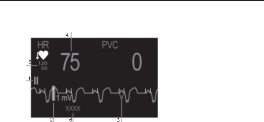
Understanding the ECG Display
6-10 ECG and Arrhythmia Monitoring
Understanding the ECG Display
Your display may be configured to look slightly different.
1. Lead label of the displayed wave
2. 1 mV calibration bar
3. Pacer spikes
4. Current heart rate
5. Current heart rate alarm limits
6. EASI lead placement label (located here when
active)
7. Paced status
ECG HR numeric: This is the heart rate derived from the monitored ECG.
Pacer Spikes: The pacer spikes are shown in white.
Draft Copy
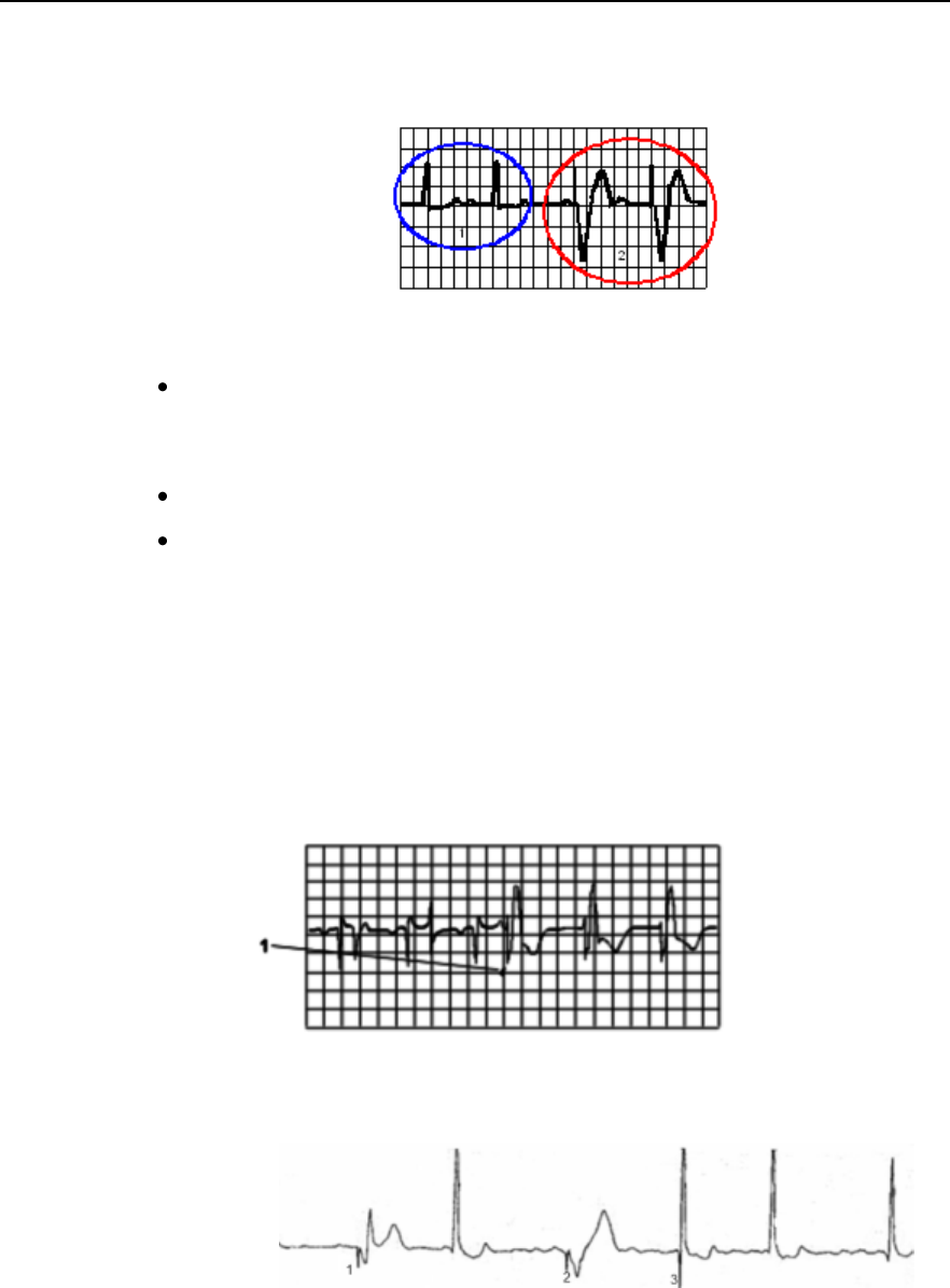
Monitoring Paced Patients
ECG and Arrhythmia Monitoring 6-11
Monitoring Paced Patients
An ECG optimized for monitoring a paced patient should look like this:
1. Normal Beats
2. Pace Pulses/Beats
Choose a lead as primary or secondary lead that has these characteristics:
the normal QRS complex should be either completely above or below
the baseline and it should not be biphasic. For paced patients, the QRS
complexes should be at least twice the height of pace pulses.
the QRS complex should be tall and narrow
the P-waves and the T-waves should be less than 0.2 mV.
Optimizing Lead Selection for Paced Patients
Some unipolar pacemakers display pace pulses with repolarization tails.
These tails may be counted as QRSs in the event of cardiac arrest or other
arrhythmias.
If you note a visible repolarization tail, choose a lead that decreases the size
of the repolarization tail.
1. Repolarization tail
(note width)
Avoid fusion and pseudofusion beats.
1. Fusion
2. Paced
3. Pseudofusion
Draft Copy

Changing the Size of the ECG Wave
6-12 ECG and Arrhythmia Monitoring
Changing the Size of the ECG Wave
If any of the displayed ECG waves is too small or clipped, you can change
the size of the ECG waves on the screen.
Changing the adjustment factor only changes the visual appearance of the
ECG wave on the MX40. It does not affect the ECG signal analyzed by the
algorithm.
Comparing the wave size to the 1 mV calibration bar on the ECG wave
segment can help you get an idea of the true ECG signal strength.
To change the size of the ECG waves on the screen by
a fixed adjustment factor:
1 Touch the HR parameter.
2 In the Setup ECG menu, scroll to the second page and select Adjust
Size.
3 Select the required adjustment factor from the list.
Size X1/2 to halve the wave size
Size X1 to display the wave without zoom
Size X2 to double the wave size
Size X4 to multiply the wave size by four
or
4 Touch the ECG wave and enter the size from the Change Wave menu.
5 Select the required adjustment factor from the list.
Draft Copy

Choosing EASI or Standard Lead Placement
ECG and Arrhythmia Monitoring 6-13
Choosing EASI or Standard Lead Placement
Choose either standard lead placement or EASI lead placement:
1 In the Setup ECG menu, select Lead Placement to toggle between
Standard or EASI.
2 Select Standard or EASI.
Note — When changing lead placement, the patient cable must be attached
to the MX40.
EASI is shown beside the 1 mV calibration bar on the ECG wave on the
display, and EASI is marked on any recorder strips and printouts.
See the sections on Lead Placement for electrode placement diagrams.
Draft Copy

Derived 12-lead ECG
6-14 ECG and Arrhythmia Monitoring
Derived 12-lead ECG
Hexad
When operating with the IntelliVue Information Center iX, the optional
Hexad algorithm generates a Mason-Likar 12-lead ECG from a 6-wire
leadset (including four limb electrodes and two chest electrodes) placed
according to the Mason-Likar 6-electrode placement.
To generate a derived 12-lead ECG using this configuration, 8 out of the 12
leads are directly acquired (I, II, III, aVR, aVL, aVF and the two
directly-recorded V leads) and only 4 precordial leads need to be derived.
This means that 8 of 12 are identical to the 12 leads acquired using a full set
of 10-wire standard ECG lead set. For more information refer to the 12 Lead
ECG Monitoring Using a Reduced Lead Set Application Note, Part Number
452296278591.
Caution
Hexad derived ECG and their measurements are approximations to the
standard ECG, and should not be used for diagnostic interpretation.
EASI
The EASI system, a method of deriving 12ECG leads using a five-electrode
configuration (4 monitoring electrodes and a ground electrode), has been
developed to better address the goals and challenges of continuous ECG
monitoring. EASI monitoring makes it possible to obtain 12-lead ECG
information under continuous monitoring conditions across the continuum
of care. The EASI method of obtaining a 12-lead ECG requires only five
electrodes. The electrodes are placed on the upper sternum (S), the lower
sternum (E) at the level of the fifth intercostal space, and on the right and
left midaxillary lines (I and A) at the same level as the lower sternum
electrode. A fifth ground electrode can be placed anywhere.
Draft Copy

ECG Configuration
ECG and Arrhythmia Monitoring 6-15
ECG Configuration
The MX40 supports 3-, 5-, and 6-wire patient cables. The 5-wire patient
cable can be used for either standard or EASI electrode configurations. The
6-wire patient cable can be used for either standard or Hexad electrode
configurations. The MX40 detects the patient cable type attached and
automatically determines the ECG measurement and transmitted leads.
Note—The labels and colors of the ECG electrodes differ according to the
standards that apply for your hospital. The electrode placement references
and illustrations in this chapter use the AAMI labels and colors. See the
table below for additional label and color information.
Electrode Labels
Electrode Colors
AAMI
EASI
IEC
AAMI
IEC
RA
I
R
White
Red
LA
S
L
Black
Yellow
LL
A
F
Red
Green
RL
N
N
Green
Black
V/Va
E
C/Ca
Brown
White
Vb
Cb
Brown/White
White/Blue
Arrhythmia analysis resides in the arrhythmia algorithm on the MX40.
Arrhythmia analysis is always turned on for telemetry patients unless
operating with the IntelliVue Information Center iX, where it can be turned
off. Arrhythmia analysis is either Basic or Enhanced (optional).
Draft Copy

ECG Leads Monitored
6-16 ECG and Arrhythmia Monitoring
ECG Leads Monitored
Depending on the patient cable connected to the MX40, a different set of
viewable leads are available at the MX40 and the Information Center. The
MX40 can source up to four raw ECG waves to the Information Center.
If you are using ...
these leads can be selected at the
MX40 and the Information Center
3-wire
I, II, III
Sourced (raw) waves are received as:
Channel 1 = I, II, or III
Factory Default is II.
5-wire (Standard mode)
I, II, III, aVR, aVL, aVF, MCL and V
Sourced (raw) waves are received as:
Channel 1 = II
Channel 2 = III
Channel 3 = MCL
Factory Defaults are II, V, III.
5-wire (EASI mode)
I, II, III, aVR, aVL, aVF, V1, V2, V3, V4, V5, V6
In EASI mode, the sourced (raw) waves are
received as:
Channel 1 = Vector 1 (A-I)
Channel 2 = Vector 2 (A-S)
Channel 3 = Vector 3 (E-S)
Factory Defaults are II, V2, III, V5.
Arrhythmia monitoring is performed only on the
primary and secondary leads selected at the
Information Center, although you can view and
perform ST analysis on all 12 EASI derived
leads.
Draft Copy

ECG Leads Monitored
ECG and Arrhythmia Monitoring 6-17
If you are using ...
these leads can be selected at the
MX40 and the Information Center
6-wire
I, II, III, aVR, aVL, aVF, V1, V2, V3, V4, V5, V6,
V7, V8, V9, V3R, V4R, V5R.
Sourced (raw) waves are received as:
Channel 1 = II
Channel 2 = III
Channel 3 = Va
Channel 4 = Vb
Factory Defaults are II, Va = V2, III, Vb = V5.
The two chest leads, Va and Vb, can be placed
on the patient in any of the V lead positions (V1
through V9, V3R, V4R, V5R). Lead assignment
is available at the Information Center. When
unassigned, the chest leads use the defaults.
Note— The lead label assigned to Vb cannot
be selected for Va even though Vb does not
appear to be used.
When display of the pleth wave is enabled at the
Information Center, the second chest lead (Vb)
is not available for monitoring.
6-wire (Hexad Mode)
I, II, III, MCL, aVR, aVL, aVF, V1-V6.
Factory Defaults = Off, V1/V3, V1/V4, V1/V5,
V2/V4, V2/V5, V3/V5, V3/V6
Derived leads are labeled, e.g. dV3.
Draft Copy

Reconstructed Leads
6-18 ECG and Arrhythmia Monitoring
Reconstructed Leads
Reconstruction of leads from the sourced wave is defined by the
calculations in the following table. EASI reconstructed leads are a linear
combination of all three raw EASI leads
ECG Lead
Clinical
Calculations in
terms of electrodes
3-wire
5-wire
Standard
6-wire
I
I
I
LA-RA
II
(default)
II (default)
II (default)
LL-RA
III
III (default)
III
(default)
LL-LA
-
MCL
V-LA, where V=C
-
aVR
aVR
RA-(LA+LL)/2
-
aVL
aVL
LA-(RA+LL)/2
-
aVF
aVF
LL-(LA+RA)/2
-
V (default)
V-(RA+LA+LL)/3, where
V=C
Va
Va-(RA+LA+LL)/3, where
Va=V2 (default) position
Vb
Vb-(RA+LA+LL)/3, where
Vb =V5 (default) position
Draft Copy
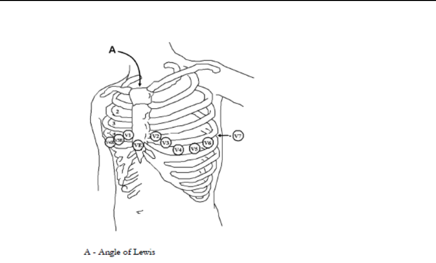
Chest Electrode Placement
ECG and Arrhythmia Monitoring 6-19
Chest Electrode Placement
V1 on the fourth intercostal space at the right
sternal border
V2 on the fourth intercostal space at the left
sternal border
V3 midway between the V2 and V4 electrode
positions
V4 on the fifth intercostal space at the left
midclavicular line
V5 on the left anterior axillary line, horizontal
with the V4 electrode position
V6 on the left midaxillary line, horizontal with
the V4 electrode position
V3R-V6R on the right side of the chest in
positions corresponding to those on the left
VE over the xiphoid process
V7 on posterior chest at the left posterior
axillary line in the fifth intercostal space
V7R on posterior chest at the right posterior
axillary line in the fifth intercostal space
For accurate chest electrode placement and measurement, it is important to
locate the fourth intercostal space.
To locate the fourth intercostal space:
1 Locate the second intercostal space by first palpating the Angle of Lewis
(the little bony protuberance where the body of the sternum joins the
manubrium). This rise in the sternum is where the second rib is
attached, and the space below this is the second intercostal space.
2 Palpate and count down the chest until you locate the fourth intercostal
space.
Draft Copy
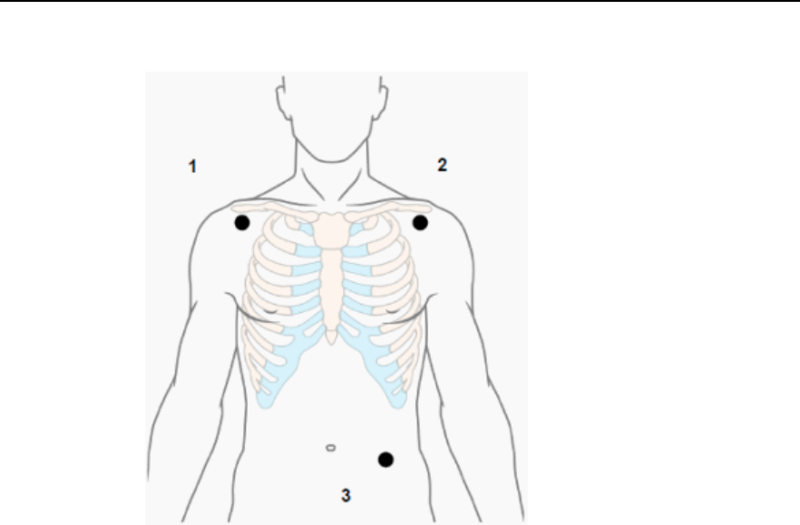
3-Wire Placement
6-20 ECG and Arrhythmia Monitoring
3-Wire Placement
1. RA - directly below the clavicle and
near the right shoulder
2. LA -directly below the clavicle and
near the left shoulder
3. LL - on the left lower abdomen
Draft Copy
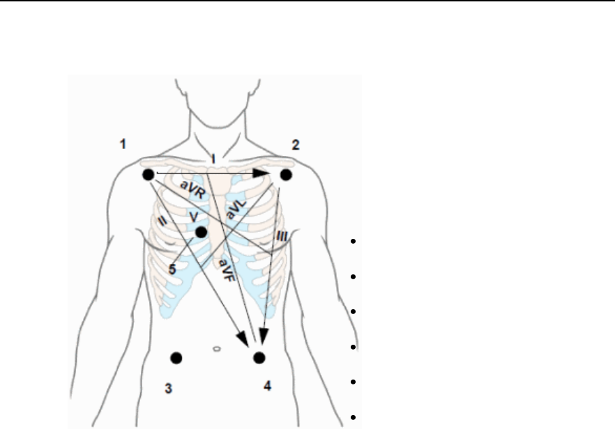
5-Wire Placement (Standard Mode)
ECG and Arrhythmia Monitoring 6-21
5-Wire Placement (Standard Mode)
1. RA directly below the clavicle and near the
right shoulder
2. LA directly below the clavicle and near the
left shoulder
3. RL on the left lower abdomen
4. LL on the right lower abdomen
5. V on the chest, the position depends on your
required lead selection.
V1 on the fourth intercostal space at the right
sternal border
V2 on the fourth intercostal space at the left
sternal border
V3 midway between the V2 and V4 electrode
positions
V4 on the fifth intercostal space at the left
midclavicular line
V5 on the left anterior axillary line, horizontal
with the V4 electrode position
V6 on the left midaxillary line, horizontal with
the V4 electrode position
Draft Copy
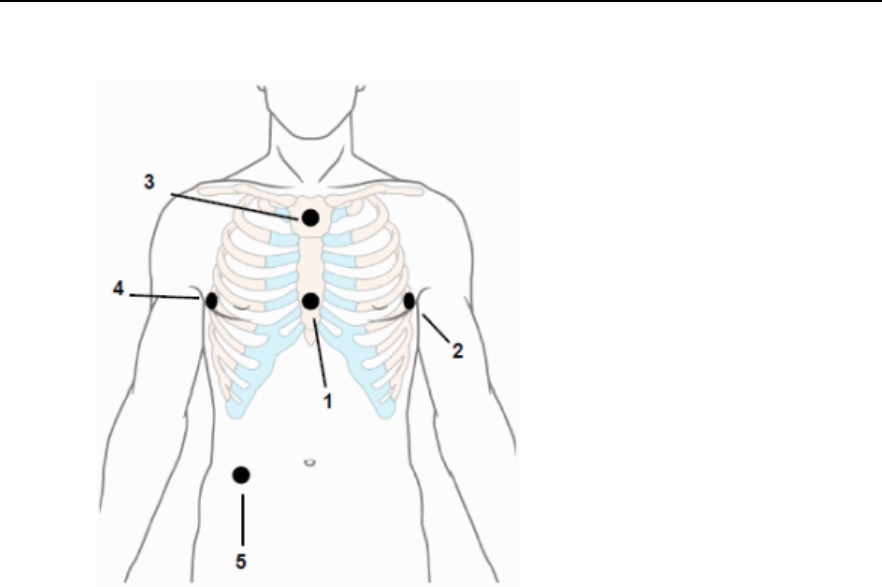
5-Wire Placement (EASI Mode)
6-22 ECG and Arrhythmia Monitoring
5-Wire Placement (EASI Mode)
1. E (V) on the lower sternum at the level of the
fifth intercostal space
2. A (LL) on the left midaxillary line at the same
level as the E electrode
3. S (LA) on the upper sternum
4. I (RA) on the right midaxillary line at the same
level as the E electrode
5. N (Reference) can be anywhere, usually below
the sixth rib on the right hip
Make sure that the S and E electrodes line up vertically on
the sternum, and that the I, E and A electrodes align
horizontally.
Draft Copy

6-Wire Placement
ECG and Arrhythmia Monitoring 6-23
6-Wire Placement
For a 6-lead placement use the positions from the 5-lead diagram above but
with two chest leads. The two chest leads, Va and Vb, can be positioned at
any two of the V1 to V6 positions shown in the chest electrode diagram
below.
The default position of Va - the brown lead - is at the V2 position.
The default position for Vb - the brown/white lead - is at the V5 position.
The lead placement for the Va and Vb lead labels must be appropriate. If
your unit uses other precordial leads for Va and Vb, they may be assigned
in Unit Settings at the Information Center as defaults for your whole unit,
or you may need to assign the new positions on a per-patient basis in the
Patient Window at the Information Center.
Selecting Positions of Va and Vb Chest Leads
The two chest leads for the 6-lead placement can be positioned at any two
of the V1 to V9 and V3R, V4R and V5R positions. Select the positions you
have used in the Patient Window at the Information Center, so that the
chest leads will be correctly labeled.
Draft Copy
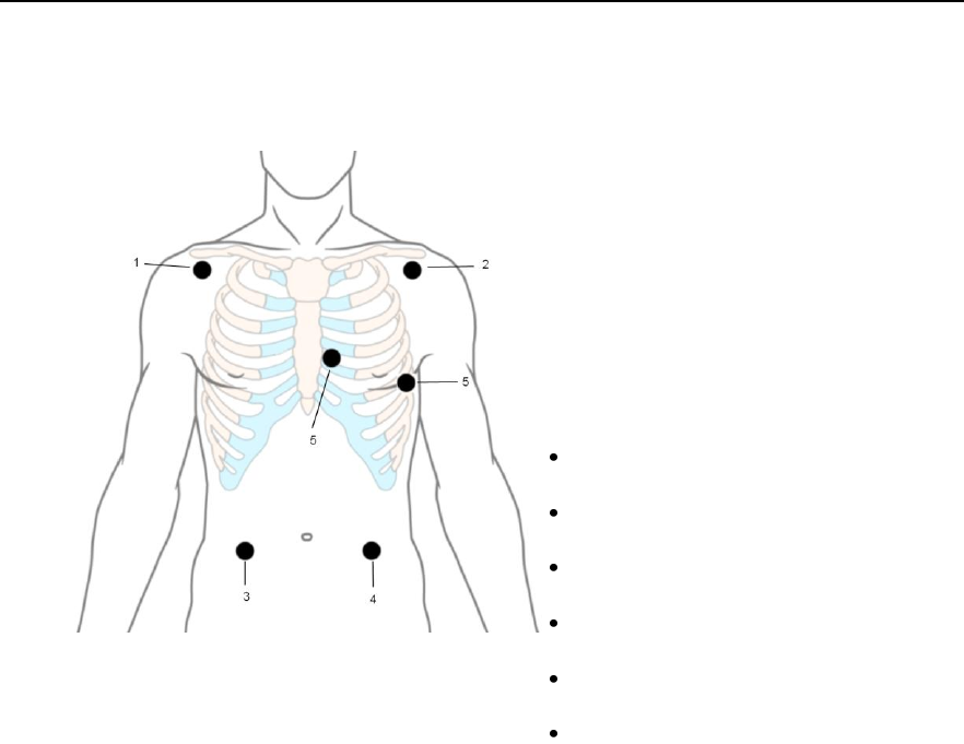
6-Wire Placement (Hexad Mode)
6-24 ECG and Arrhythmia Monitoring
6-Wire Placement (Hexad Mode)
The diagram below shows the Mason-Likar Placement for 12-Lead ECG
using 6 electrodes.
Note — In Hexad mode, V leads are chosen in pairs at
the IntelliVue Information Center iX.
1. RA directly below the clavicle and near the
right shoulder
2. LA directly below the clavicle and near the
left shoulder
3. RL on the left lower abdomen
4. LL on the right lower abdomen
5. V on the chest, the position depends on your
required lead selection. The typical position is
V1, although this may vary according based
on your hospital’s protocol.
V1 on the fourth intercostal space at the right
sternal border
V2 on the fourth intercostal space at the left
sternal border
V3 midway between the V2 and V4 electrode
positions
V4 on the fifth intercostal space at the left
midclavicular line
V5 on the left anterior axillary line, horizontal
with the V4 electrode position
V6 on the left midaxillary line, horizontal with
the V4 electrode position
Draft Copy

Monitoring during Leads Off
ECG and Arrhythmia Monitoring 6-25
Monitoring during Leads Off
ECG Fallback and Extended monitoring states are supported for the MX40
when the primary and/or secondary leads are in a "Leads Off" INOP
condition. Both of these states are entered into after 10 seconds of "Leads
Off" in an attempt to maintain monitoring and arrhythmia analysis.
ECG Fallback
ECG Fallback occurs when the primary lead is in "Leads Off" for 10 seconds
and a secondary lead is available.
Multilead Analysis
If there is a "Leads Off" technical alarm in the primary lead for > 10 seconds,
the active secondary lead becomes the primary lead. The arrhythmia
algorithm switches the leads on the display, but relearn does not occur.
When the "Leads Off" condition is corrected, the leads are switched back to
their original state.
Single Lead Analysis
For single lead analysis, if there are two leads available, the secondary lead
is made the primary lead until the "Leads Off" condition is corrected. The
arrhythmia algorithm performs a relearn using the available lead.
Extended Monitoring
If both the primary and secondary leads are in a "Leads Off" condition, the
ECG source on the MX40 will switch to any available lead. Relearning will
occur in this condition.
Fallback for EASI
If one of the derived EASI leads is in a technical alarm condition, a flat line
is displayed. After 10 seconds, the directly acquired EASI AS, EA, or AI
lead, depending on which is available, is displayed. Arrhythmia relearn is
performed with transition to or from EASI Fallback monitoring using the
available lead(s).
Relearning
Whenever there is a "Leads Off" condition for more than 60 seconds, the
arrhythmia algorithm performs a Relearn using the available leads.
Draft Copy

Monitoring during Leads Off
6-26 ECG and Arrhythmia Monitoring
Warning
Since Relearn happens automatically, if learning takes place during
ventricular rhythm, the ectopics can be incorrectly learned as the normal
QRS complex. This can result in missed detection of subsequent events of
V-Tach and V-Fib. For this reason, you should:
1 Respond promptly to any technical alarm.
2 Ensure that the arrhythmia algorithm is labeling beats correctly.
Draft Copy

ST/AR Arrhythmia Monitoring
ECG and Arrhythmia Monitoring 6-27
ST/AR Arrhythmia Monitoring
ST/AR Arrhythmia Algorithm
Indications for Use
The ST/AR Arrhythmia Algorithm is indicated for use in instances where
the clinician decides to monitor cardiac arrhythmias of adult and pediatric
patients and/or the ST segment of adult patients to gain information for
treatment, monitor the adequacy of treatment, or to exclude causes of
symptoms.
How the ST/AR Algorithm Works
ST/AR multi-lead analysis is performed on the user-selected primary and
secondary leads. If only one lead is available for multilead, ST/AR analysis
is performed on the single available lead.
Arrhythmia analysis consists of several steps:
1 The ECG signal is pre-processed to filter out baseline wander, muscle
artifact, and signal irregularities. In addition, if the Paced status = On,
pace pulses are detected then rejected from the processing to avoid
seeing them as QRS beats.
2 Beat detection to locate the QRS complexes for further analysis.
3 Feature measurement such as R-wave height, width, and timing.
4 Beat classification. Templates are created and are matched to incoming
beats, and the appropriate beat label is determined.
5 Atrial Fibrillation Detection. Analyzes the RR intervals and P waves.
6 Ventricular Fibrillation Detection. Looks for a flutter or sinusoidal wave
pattern in both ECG channels
7 Rhythm and alarm detection. Beat labels are used to produce the values
and events needed to generate rhythms and alarms.
Working in parallel with beat detection and classification, a separate
detector examines continuously for ventricular fibrillation, asystole, and
noise.
The quality of the ECG signal is important for accurate arrhythmia analysis.
The section below provides guidelines for optimizing signals for
arrhythmia analysis.
Draft Copy

ST/AR Arrhythmia Monitoring
6-28 ECG and Arrhythmia Monitoring
For additional information on the ST/AR Algorithm, refer to the Arrhythmia
Monitoring ST/AR Algorithm Application Note.
Aberrantly-Conducted Beats
As P-waves are not analyzed, it is difficult and sometimes impossible for
the monitor to distinguish between an aberrantly-conducted
supraventricular beat and a ventricular beat. If the aberrant beat resembles
a ventricular beat, it is classified as ventricular. You should always select a
lead where the aberrantly-conducted beats have an R-wave that is as
narrow as possible to minimize incorrect calls. Ventricular beats should
look different from these 'normal beats'. Instead of trying to select two leads
with a narrow R-wave, it may be easier to just select one lead and use single
lead arrhythmia monitoring. Extra vigilance is required by the clinician for
this type of patient.
Atrial Fibrillation Alarm
The MX40 performs atrial fibrillation analysis using information about the
RR irregularity, PR interval variability, and P-wave variability.
In order to generate an Afib alarm the following criteria must be detected
for 1 minute:
normal beat RR intervals must be irregular
PR interval deviation must be large
P-wave region must not match well
Atrial fibrillation analysis is only available for adult patients and atrial
fibrillation detection cannot be performed on PVCs or Paced beats.
An *End AFIB alarm will occur when no atrial fibrillation waveform is
detected for a configured delay time.
Since most atrial flutters have regular RR intervals, they cannot be detected
by the atrial fibrillation algorithm.
An *AFIB alarm can be falsely detected in the presence of:
sinus arrhythmia
muscle noise, or
electrode motion artifact
Draft Copy

ST/AR Arrhythmia Monitoring
ECG and Arrhythmia Monitoring 6-29
Intermittent Bundle Branch Block
Bundle branch and the other fascicular blocks create a challenge for the
arrhythmia algorithm. If the QRS during the block changes considerably
from the learned normal, the blocked beat may be incorrectly classified as
ventricular, causing false PVC alarms. You should always select a lead
where the bundle branch block beats have an R-wave that is as narrow as
possible to minimize incorrect calls. Ventricular beats should look different
from these 'normal beats'. Instead of trying to select two leads with a
narrow R-wave, it may be easier to just select one lead and use single lead
arrhythmia monitoring. Extra vigilance is required by the clinician for this
type of patient.
ECG and Arrhythmia Alarm Overview
The ECG and arrhythmia alarms available depend on which measurements
are switched on, and the arrhythmia option enabled for your MX40.
Cardiotach alarms are available when HR is on and the active alarm
source is ECG, but arrhythmia s switched off.
Basic arrhythmia alarms are available when Arrhythmia is switched on.
Enhanced arrhythmia alarms are available when Arrhythmia is
switched on and the Enhanced Arrhythmia option has been enabled for
your MX40.
To check your enabled settings, view the Standby screen.
Cardiotach Alarms
Additional Alarms with
Basic Arrhythmia Option
Additional Alarms with
Enhanced Arrhythmia
Option
***Asystole
***Ventricualr Fibrillation/
Tachycardia
***Extreme Bradycardia
***Extreme Tachycardia
*/**High heart rate
*/**Low heart rate
***Ventricular Tachycardia
*Pacer Not Capture
*Pacer Not Pacing
*PVCs/min HIGH (PVC >
limit/min)
*Afib
*End Afib
*Supraventricular Tach
*Missed Beat
*Pause
*Irregular HR
*End Irregular HR
*Ventricular Rhythm
*Run PVCs High
*Pair PVCs
*R-on-T PVCs
*Ventricular bigeminy
*Ventricular trigeminy
*Non-sustain VT
*Multiform PVCs
Draft Copy
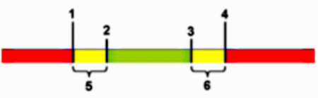
ST/AR Arrhythmia Monitoring
6-30 ECG and Arrhythmia Monitoring
Note — When operating with the IntelliVue Information Center Release N
or earlier, the ST/AR Arrhythmia Algorithm operates and generates alarms
independently at both the MX40 and the Information Center. Therefore,
you may see slight differences between the two, even though the alarm
settings and limits are the same.
Using ECG Alarms
At the Information Center, ECG alarms can be switched on and off and the
high and low alarm limits changed just like other measurement alarms, as
described in the Alarms chapter. Special alarm features which apply only to
ECG are described here.
Extreme Alarm Limits for Heart Rate
The extreme rate alarms, Extreme Tachy and Extreme Brady, are set at the
Information Center by adding a set value (the D value) to the high and low
alarm limits.
1. Extreme Brady Limit
2. Low Limit
3. High Limit
4. Extreme Tachy Limit
5. Extreme Brady (D value)
6. Extreme Tachy (D value)
You need to know which value has been configured for your monitor.
Changing the high and low alarm limits automatically changes the extreme
alarm limits within the allowed range.
Arrhythmia Alarm Settings
Some arrhythmia alarms can be turned off at the Information Center
depending its configuration. They are:
Non-Sustain VT, Vent Rhythm, Run PVCs, Pair PVCs, R-On-T PVC,
V.Bigeminy, V.Trigeminy, Multif.PVCs, Pause, SVT, HR High, HR Low
Irregular HR (IHR), Missed Beat, PVCs/min, Pacer Not Capture, Pacer
Not Pacing,and Afib.
Alarms that have been turned off at the Information Center will appear as
off in the Arrhythmia menu of the MX40, but they are not accessible, nor
can you change limits locally.
Draft Copy

ST/AR Arrhythmia Monitoring
ECG and Arrhythmia Monitoring 6-31
Yellow Arrhythmia Alarms
Yellow arrhythmia alarms are short yellow alarms specific to
arrhythmia-related patient conditions. Depending on your Information
Center configuration, they may be shown with one or two stars. The heart
rate alarms (High HR and Low HR) can be configured as short yellow or
standard yellow alarms. When they are standard yellow alarms they exist
independently of the other arrhythmia alarms and no timeout periods
apply.
Warning
When arrhythmia analysis is on, all yellow ECG and arrhythmia alarms are
short yellow alarms (one-star). This means that the alarm tones (if volume
is on) are active for six seconds only, after which the blinking numeric and
the alarm message remain for up to three minutes. The only exception to
this are the HR High and Low alarms which can be configured as standard
yellow alarms. Red alarms behave as usual.
Viewing Arrhythmia Waves
To view arrhythmia beat labels:
1 Go to the Setup ECG menu.
2 Select Arrhythmia.
3 Change Annotate Arrhy from Off to On. Beat labels will be annotated
above the ECG wave and Delayed will appear beside it.
To return to the normal ECG primary lead display:
1 Select Annotate Arrhy.
2 Change to Off.
3 Exit from the Setup ECG menu.
Draft Copy
ST/AR Arrhythmia Monitoring
6-32 ECG and Arrhythmia Monitoring
Arrhythmia Beat Labels
Arrhythmia beat labels tell you how the monitor is classifying beats.
N = Normal
V = Ventricular Ectopic
S = Supra-ventricular Premature
P = Paced
' = Pacer spike
" = Biventricular Pacer Spike
L = Learning patient's ECG
A = Artifact (noisy episode)
? = Insufficient information to classify beats
I = Inoperative condition (e.g., LEADS OFF)
M = Pause or missed beat
Draft Copy

ST/AR Arrhythmia Monitoring
ECG and Arrhythmia Monitoring 6-33
Enhanced Arrhythmia Chain
The diagram below shows the alarm condition priority chains for enhanced
arrhythmia. The alarm conditions in each category are prioritized according
to the level of seriousness.
Red Alarms Chain
Asystole
↓
V-FIB/TACH
↓
V-TACH
↓
Extreme Tachy/Extreme Brady
Yellow Arrhythmia Alarms
PVC Alarms Chain
Rate Alarms Chain
Beat Detection Alarms
Chain
Afib/End Afib
↓
lHR/End IHR
Non Sustain VT/Vent Rhythm
↓
Run PVCs
↓
Pair PVCs
↓
R-On-T PVCs
↓
SVT
↓
HR > xxx or HR < xxx
Pause
↓
Pacer Not Capture/Pacer Not
Pace/Missed Beat.
First Level Timeout Period
----------------------------------------------------------------------------------------------------------------------------
Second Level Timeout Period
Vent Bigeminy
↓
Vent Trigeminy
↓
PVCs >xx/min
↓
Multiform PVCs
Draft Copy
ST/AR Arrhythmia Monitoring
6-34 ECG and Arrhythmia Monitoring
Basic Arrhythmia Chain
The diagram below shows the alarm condition priorities for basic
arrhythmia and the timeout levels for yellow alarm conditions.
Red Alarms
Asystole
↓
V-FIB/TACH
↓
V-TACH
↓
Extreme
Tachy/Extreme
Brady
↓
Yellow Arrhythmia Alarms
PVC Alarms Chain
Beat Detection
Alarms Chain
Rate Alarms Chain
Pacer Not
Capture/Pacer
Not Pace
HR > xxx or HR < xxx
First Level Timeout Period
----------------------------------------------------------------------------------------------------------------------------------------------------------
Second Level Timeout Period
PVCs >xx/min
Learning
The arrhythmia system’s goal is to learn the patient’s normal complexes so
it can differentiate abnormal beats. This "learning" process uses the 15 first
valid beats (for example, free from noise) encountered during the learning
phase.
While the system is learning the complex, the delayed arrhythmia wave
displays the beat label "L".
Learning Phase
A learning phase involves the system learning the patient’s dominant
complexes. During a learning phase:
Draft Copy

ST/AR Arrhythmia Monitoring
ECG and Arrhythmia Monitoring 6-35
Alarm timeout periods are cleared.
Stored arrhythmia templates are cleared.
Asystole, Vfib, and HR alarms (when there are enough beats to
compute the HR) are active.
All other alarms are not active.
Single Lead Analysis
If single lead analysis is selected, the arrhythmia system begins learning
whenever:
ECG monitoring is initiated.
The Relearn Arrhy control is activated. See Initiating Arrhythmia
Relearning Manually p. 6-36.
The ECG Lead or Lead Label is changed manually, or when Fallback
occurs. See Fallback.
A "LEADS OFF" INOP condition (that has been active for >60 seconds)
ends.
When the MX40 re-associates with the Information Center.
Multilead Analysis
If multilead analysis is selected, the arrhythmia system begins a learning on
both leads whenever:
ECG monitoring is initiated.
The Relearn Arrhy control is activated (see Initiating Arrhythmia
Relearning Manually p. 6-36).
There has been a Leads Off INOP condition (that has been active for >60
seconds) for both leads, and the condition ends in either lead.
When the MX40 re-associates with the Information Center.
Multilead Analysis With Changes in One Lead
Since the arrhythmia system uses more than one lead for analysis, if there is
a change in one lead, the system does a relearn only on the affected lead.
This happens whenever:
An ECG lead or label is changed.
A Leads Off INOP condition (that has been active for >60 seconds) ends.
Draft Copy

ST/AR Arrhythmia Monitoring
6-36 ECG and Arrhythmia Monitoring
Note — During this learning phase the system will continue monitoring
using the operative lead. Therefore, the delayed arrhythmia wave is not
labeled "L". In addition:
Alarm timeout periods are maintained.
Stored arrhythmia templates are maintained for the operative lead.
All alarms turned on are active.
EASI ECG Monitoring
Whenever there is an INOP condition, the arrhythmia algorithm performs a
Relearn, using the available lead.
Warning
Since Relearn happens automatically, if learning takes place during
ventricular rhythm, the ectopics may be incorrectly learned as the normal
QRS complex. This may result in missed detection of subsequent events of
V-Tach and V-Fib. For this reason, you should:
1 Respond to the INOP message (for example, re-connect the electrode(s).
2 Ensure that the arrhythmia algorithm is labeling beats correctly.
Initiating Arrhythmia Relearning Manually
To initiate relearning manually, in the Setup ECG menu, select Relearn
Arrhy.
While the monitor is learning, if annotate arrhythmia is On, the delayed
arrhythmia wave displays the beat label L.
Next, the monitor determines the dominant rhythm. The beats are
labeled N.
After relearning is complete, you should check the delayed arrhythmia
wave to ensure that the algorithm is labeling the beats correctly. See
Arrhythmia Beat Labels p. 6-31.
If beats are still not classified correctly, check that the ECG is optimized for
arrhythmia monitoring. You may need to select a different lead or change
the electrodes or electrode positions if there is excessive noise, unstable
voltage, low amplitude, or large P- or T-waves.
Draft Copy

ST/AR ST Analysis Algorithm
ECG and Arrhythmia Monitoring 6-37
ST/AR ST Analysis Algorithm
Introduction
The intended use of the ST/AR ST Analysis algorithm is to monitor an adult
patient’s ECG for ST segment elevation or depression and produce
events/alarms for all possible ECG leads. The ST Analysis algorithm is
capable of monitoring paced and non-paced adult patients.
The ST/AR ST algorithm monitors ST segment elevation or depression for
each available telemetry ECG lead and produces events/alarms
simultaneously.
Note—The ST Analysis algorithm does not analyze ventricularly paced or
ventricular ectopic beats.
Warning
This device provides ST level change information; the clinical significance
of the ST level change information needs to be determined by a physician.
ST values update with every measurement period and enunciate,
depending upon the severity of the change, events and alarms as they are
detected.
The ST/AR ST algorithm is approved for use only with adult non-paced
and atrially-paced patients.
Caution
Some clinical conditions may make it difficult to achieve reliable ST
monitoring, for example:
if you are unable to select a lead this is not noisy
if arrhythmias such as atrial fib/flutter are present, which may cause an
irregular baseline
if the patient is continuously ventricularly paced
if the patient has left bundle branch block
Draft Copy
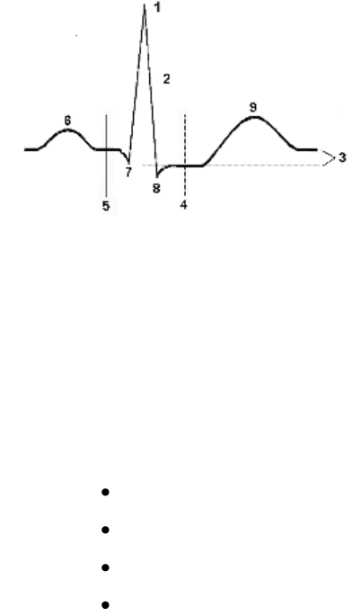
ST/AR ST Analysis Algorithm
6-38 ECG and Arrhythmia Monitoring
The Measurements
Overview
The ST/STE measurement for each beat complex is the vertical difference
between two measurement points. The isoelectric point provides the
baseline for both measurements.
The ST measurement uses the isoelectric point and the ST point. The ST
point is positioned with reference to the J-point.
The STE measurement uses the isoelectric point and the J point.
1. R-wave peak at 0 msec
2. J point
3. Difference = ST value
4. ST measurement point. Default = J+60 msec
5. Isoelectric point. Default = -80 msec
6. P
7. Q
8. S
9. T
You can manually adjust the ST/STE measurements on the Information
Center's Measurements application.
Turning ST or STE On and Off
ST and STE analysis can be turned on and off independently. You would
turn ST/STE monitoring off if:
You are unable to get any lead that is not noisy.
Arrhythmias such as atrial fib/flutter cause irregular baseline.
The patient is continuously ventricularly paced.
The patient has left bundle branch block.
To turn all ST or STE monitoring on or off at the
IntelliVue Information Center iX:
1 Select the Measurements ST page.
2 Click the I/O ST or I/O STE Analysis button to toggle ST or STE
Analysis on or off as appropriate.
Draft Copy

ST/AR ST Analysis Algorithm
ECG and Arrhythmia Monitoring 6-39
To turn ST monitoring on or off at the IntelliVue
Information Center Release N:
1 From the Patient Window, click the All Controls button.
2 From the All Controls Window, click the ST Setup button.
3 From the ST Setup Window, click ST On/Off as appropriate.
Displayed ST Data
ST data displays as values in the Patient Sector and Patient Window at the
Information Center. At the MX40, three ST values can be displayed below
the ECG wave. A positive value indicates ST segment elevation; a negative
value indicates ST segment depression. You can view ST data at the MX40
if ST is assigned to a numeric area. Up to 3 values can display in the
assigned space. If more than three values area available, the last value will
rotate.
Displayed STE Data
STE Data can only be displayed in the Measurements application STE page
at the Information Center iX.
Note — ST/STE data and alarms are only displayed at the MX40 when
operating with IntelliVue Information Center iX.
ST Lead Groups
ECG Leads are clinically grouped as follows:
ST Lead Group
ECG Leads
Inferior
II, III, aVF
Lateral
I, aVL, V5, V6
Antero-lateral
I, aVL, V4, V5, V6
Anterior
V1, V2, V3, V4
Septal
V1, V2, V3
Right
V3R, V4R, V5R
Posterior
V7, V8, V9
You can change the group displayed using the ST Views menu.
Draft Copy

ST/AR ST Analysis Algorithm
6-40 ECG and Arrhythmia Monitoring
Derived 12 Lead ECG
In view of the high degree of redundancy among the standard 12-lead ECG
leads, it is quite conceivable that a more practical leadset with a smaller
number of judiciously chosen leads can be used to reconstruct the missing
leads. For Hexad derived 12-lead the-6 electrode configuration is the
feasibility of deriving additional chest leads if the two chest electrodes are
placed in several pre-specified standard precordial locations. Using a
standard 5-electrode set in EASI lead placement you can monitor up to 12
standard ECG leads simultaneously and continuously at the bedside. EASI
provides a monitoring method for trending ST segment changes that can
provide an early indication of ischemia.
Caution
Derived ECG and their measurements are approximations to the standard
ECG, and should not be used for diagnostic interpretation.
EASI ST Analysis
With EASI monitoring, ST analysis is performed on up to 12 leads, and an
additional value of ST index is calculated and displayed. Assessment of
EASI-derived 12-lead ST measurement is recommended for adult patients
that meet the following parameters:
Ages: 33-82 years
Heights: 147 to 185 cm (58 to 73 in)
Weights: 53 to 118 kg (117 to 261 lbs)
Height to Weight Ratios: 1.41 to 2.99 cm/kg (0.25 to 0.54 in/lb)
For additional information on ST monitoring, refer to the ST Segment
Monitoring Application Note, Part Number 452296278611.
ST values are presented in the patient sector and Patient Window for EASI
derived leads along with STindx (ST Index). STindx is a summation of three
ST segment measurements, using the leads that can indicate ST segment
changes in the different locations of the heart:
anterior lead V2
lateral lead V5
inferior lead aVF
Draft Copy
ST/AR ST Analysis Algorithm
ECG and Arrhythmia Monitoring 6-41
HEXAD ST Analysis
When operating with the IntelliVue Information Center iX, the optional
Hexad algorithm generates a Mason-Likar 12-lead ECG from a 6-wire
leadset (including four limb electrodes and two chest electrodes) placed
according to the Mason-Likar 6-electrode placement.
To generate a derived 12-lead ECG using this configuration, 8 out of the 12
leads are directly acquired (I, II, III, aVR, aVL, aVF and the two
directly-recorded V leads) and only 4 precordial leads need to be derived.
This means that 8 of 12 are identical to the 12 leads acquired using a full set
of 10-wire standard ECG lead set. For more information refer to the 12 Lead
ECG Monitoring Using a Reduced Lead Set Application Note, Part Number
452296278591.
ST Alarms
ST Alarms are yellow alarms. They are announced after exceeding alarm
limits for one minute. ST Alarm Limits can only be set at the Information
Center. Each ST lead has its own alarm limit. ST alarms are triggered when
an ST value exceeds its limit for more than one minute. Turning ST Alarms
off turns off alarms for all ST leads.
STE Alarms
The STE Alarm is a yellow alarm. It is announced after exceeding alarm
limits for one minute. It can be turned on and off at the Information Center,
however its limits are not adjustable. The STE alarm limits are gender
specific and can be set individually for limb leads, V2/V3 leads, and
V1/V4/V5/V6 leads. The default values, for example on V2 and V3 1.5 mm
for females and 2.0 mm for males, are based on the recommendations from
the American Heart Association and American College of Cardiology.
The ST Elevation measurements with automated J-point determination
generate ST Elevation alarms, in addition to the ST measurements at the
user-defined ST point (J+offset), which may be useful for ST depression
alarms. When ST and STE analysis are both in use, this may result in
redundant alarms for ST elevations. Because of the different measurement
points, there may be different values obtained. Thus there could be an ST
alarm and an STE alarm but the STE alarm may announce sooner based
upon the values obtained.
Draft Copy
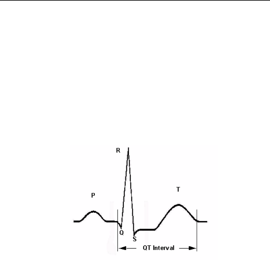
QT Interval Monitoring
6-42 ECG and Arrhythmia Monitoring
QT Interval Monitoring
Of special concern for QT monitoring is the administration of QT
prolonging drugs to patients identified with risk factors for Torsade de
Pointe. Females, older patients and patients with bradycardia, impaired left
ventricular function (ischemia, left ventricular hypertrophy), hypokalemia
and hypomagnesemia are in this increased risk category.
QT interval monitoring can assist in the detection of prolonged QT interval
syndrome. The QT interval in an ECG lead is the time interval from the
onset of the earliest deflection in the QRS complex to the end of the T wave.
For patients being monitored by the MX40, the Information Center
measures the QT interval once every minute during startup, during the
learning phase and on lead mode change. After that the Information Center
updates the QT values every five minutes.
The QT interval has an inverse relationship to heart rate. Faster heart rates
shorten the QT interval and slower heart rates prolong the QT interval. To
correct the QT interval for heart rate the Information Center uses the Bazett
correction formula by default. Your system, however, may be set up to use
the Fridericia correction formula as an alternative. The heart rate corrected
QT interval is abbreviated as QTc.
Note — When operating with the IntelliVue Information Center Release N
or earlier, QT Data is not displayed at the MX40
Draft Copy

QT Interval Monitoring
ECG and Arrhythmia Monitoring 6-43
Intended Use
The intended use of the ST/AR QT/QTc analysis is for use by the physician
in the risk assessment process indicated for pediatric and adult patients
with and without symptoms of arrhythmia. QT measurement is intended to
be used by qualified health professionals in hospital or clinical
environments. Composite QT (single or multi-lead derived) measures the
interval only and is not intended to produce any interpretation or diagnosis
of those measurements. Additional information regarding QT monitoring
can be found in the QT Interval Monitoring Application Note, Part Number
452296278601.
Warning
The device provides QT and QTc interval change information; the clinical
significance of the QT and QTc interval change information should be
determined by a clinician.
How the QT Analysis Algorithm Works
The Information Center measures the QT values once every minute during
startup. Subsequently, the Information Center updates the QT values every
five minutes. Normal or atrial paced beats and beats with a similar
morphology are averaged to form a representative waveform for further
processing. Normal beats followed by a premature QRS will be excluded
from the measurements to prevent the premature beat from obscuring the
end of the T-wave. If the algorithm cannot form a representative waveform,
for example because the morphology of the beats is too varied, the
Information Center generates a Cannot Analyze QT INOP when it detects
two consecutive invalid 5 minute values. This is also the case if normal
beats have been falsely labeled so that the algorithm does not have enough
valid beats to make QT measurements. No QT value is calculated if the
QT-HR is >150 bpm (Adult) or >180 bpm (Pediatric).
Because of the different algorithm approaches, a QT/QTc measurement
from a diagnostic 12-lead program may differ from the realtime
measurement.
For QT interval monitoring to be effective, basic or enhanced arrhythmia
monitoring must be on.
Draft Copy

QT Interval Monitoring
6-44 ECG and Arrhythmia Monitoring
Adjusting QT Settings
For patients being monitored by the MX40, you can turn QT Monitoring
on/off and adjust QT settings at the IntelliVue Information Center.
To turn QT Monitoring on/off at the IntelliVue
Information Center Release N:
1 From the Patient Window, click the All Controls button.
2 From the All Controls Window, click the QT Setup button.
3 From QT Setup, click the QT Analysis On checkbox.
QT analysis is on when a checkmark displays in the check box. When the
QT measurement is on, a QT status message is displayed in the QT Setup
window, along with the current values for QT, QTc, dQTc and QT-HR. The
lead labels indicating the leads used to calculate the baseline and current
values also appear.
To turn QT Monitoring on/off at the IntelliVue
Information Center iX:
1 Select the Measurements button from the Main Setup Window.
2 From the Measurements Window, select QT.
3 Click the I/O QT Analysis button to toggle on or off as appropriate.
The table below provides descriptions for each of the QT measurement
descriptions.
Measurement
Definition
QT
QT interval in milliseconds. The QT interval is the time between the
beginning of the Q-wave and the end of the Twave.
QTc
QTc represents the heart rate corrected QT interval. By default, the
Information Center uses the Bazett correction formula to correct
the QT interval for heart rate. Your system, however, may be set
up to use the Fridericia correction formula.
dQTc
The difference between the current QTc value and the QTc
baseline value.
QT-HR
The heart rate used to calculate QTc
Note—Turning QT analysis off does not clear the baseline value. This
allows you to turn QT analysis off during prolonged arrhythmias, such as
bigeminy, without losing the baseline.
Draft Copy

QT Interval Monitoring
ECG and Arrhythmia Monitoring 6-45
Limitations for QT Monitoring
Some conditions may make it difficult to achieve reliable QT monitoring.
When this occurs the CANNOT ANALYZE QT INOP message displays at
the Information Center, along with a QT STATUS message. Some
conditions that may make reliable QT monitoring difficult include:
T-Wave Detection Limitations.
Flat T-wave, atrial Fibrillation or atrial Flutter and prominent U-waves
can make QT monitoring difficult. For these cases you should select All
as the QT Lead on the QT window. The Information Center will use the
lead or leads that have a T-wave with sufficient amplitude and can be
detected. Alternatively select a single lead with a good T- wave
amplitude and no visible flutter activity and without a predominant
U-wave or P-wave.
QRS Changes
QRS changes such as widened QRS can affect QT monitoring. If a long
QTc is observed verify that is not caused by QRS widening.
Rhythm and Rate Limitations
Rhythm and rate limitations such as high heart rate (> 150 beats/min for
adults patients or > 180 beats/min for pediatric or neonatal patients),
paced rhythm and bigeminy rhythm can make reliable QT monitoring
difficult. If rhythm is sustained you may want to consider turning QT
interval monitoring off.
Draft Copy
QT Interval Monitoring
6-46 ECG and Arrhythmia Monitoring
Draft Copy
Monitoring Pulse Rate 7-1
7. Monitoring Pulse Rate
This section provides an introduction to the Pulse measurement and its
application.
Pulse Rate Measurement .......................................................................... 7-2
Displaying the Pulse Rate Measurement at the MX40 ......................... 7-3
Draft Copy

Pulse Rate Measurement
7-2 Monitoring Pulse Rate
Pulse Rate Measurement
The pulse rate measurement counts the arterial pulsations that result from
the mechanical activity of the heart in beats per minute (bpm). The pulse
rate is derived from the SpO2 measurement. Displayed results can range
from 30 to 300 bpm. There is no alarm function for pulse rate.
The pulse numeric is displayed at the Information Center only when SpO2
is being measured continuously. Manual measurements are displayed at
the MX40 with a time stamp. There are no alarms associated with the pulse
measurement. Pulse is turned on in the Telemetry Setup window at the
IntelliVue Information Center Release N or earlier and using the
Measurements/SpO2 page at the IntelliVue Information Center iX.
Draft Copy

Displaying the Pulse Rate Measurement at the MX40
Monitoring Pulse Rate 7-3
Displaying the Pulse Rate Measurement at the
MX40
To display the pulse rate measurement at the MX40:
1 If not already selected, press the Main Screen button and select the 1
waveform with 4 numerics display.
2 If pulse is not already displayed, touch a numeric.
3 Select Change Numeric.
4 Select Pulse.
Draft Copy
Displaying the Pulse Rate Measurement at the MX40
7-4 Monitoring Pulse Rate
Draft Copy
Monitoring Respiration Rate (Resp) 8-1
8. Monitoring Respiration Rate
(Resp)
This section provides an introduction to the Respiration Rate measurement
and its application.
Note — Resp is only available with theIntelliVue Information Center iX.
Respiration Rate Measurement ............................................................... 8-2
Resp Safety Information ........................................................................... 8-3
Lead Placement for Monitoring Resp ..................................................... 8-4
Displaying Resp on the MX40 ................................................................. 8-5
Draft Copy

Respiration Rate Measurement
8-2 Monitoring Respiration Rate (Resp)
Respiration Rate Measurement
For the respiratory measurement (Resp), the MX40 measures the thoracic
impedance between two ECG electrodes on the patient's chest. Changes in
the impedance due to thoracic movement produce the Resp waveform on
the display. The MX40 counts the waveform cycles to calculate the
respiration rate (RR).The waveform size can be set using the Setup Resp
menu which is displayed when you touch the Resp measurement area.
Settings for Resp On/Off, alarms, alarm limits and apnea time are defined at
the Information Center. When the ECG measurement is turned off, the Resp
measurement is also turned off.
Note — The Resp measurement is not available when the MX40 is
wirelessly connected to MP5T, MP2, or X2 patient monitors. When not
connected wirelessly to a monitor and Resp is being measured, the message
SRR Unavail w/ Resp is displayed on the MX40.
Draft Copy

Resp Safety Information
Monitoring Respiration Rate (Resp) 8-3
Resp Safety Information
Warning
Apnea The respiration measurement does not recognize obstructive and
mixed apneas. It only indicates an alarm when a pre-adjusted time has
elapsed since the last detected breath.
Resp Accessories To monitor respiration, use only non-OR ECG
accessories as listed in the Accessories Appendix.
Rate Adaptive Pacemakers Implanted pacemakers which can adapt to
the Minute Ventilation rate may occasionally react on the Impedance
measurement used by devices for the determination of the Resp value and
execute pacing with the maximum programmed rate. Turning off the Resp
measurement can prevent this.
Draft Copy

Lead Placement for Monitoring Resp
8-4 Monitoring Respiration Rate (Resp)
Lead Placement for Monitoring Resp
Correct patient skin preparation techniques for electrode placement are
important for Resp measurement. See Connecting and Positioning ECG
Electrodes p. 6-6.
The Resp measurement uses the standard MX40 patient cable. You can use
3-wire, 5-wire, or 6-wire leadsets, using either Standard or EASI placement.
Optimizing Lead Placement for Resp
If you want to measure Resp and you are already measuring ECG, you may
need to optimize placement of the two electrodes between which Resp will
be measured. Repositioning ECG electrodes from standard positions,
especially when you are using EASI placement, results in changes in the
ECG waveform and may influence ST and arrhythmia interpretation.
Cardiac Overlay
Cardiac activity that affects the Resp waveform is called cardiac overlay.
Cardiac overlay happens when the Resp electrodes pick up impedance
changes caused by the rhythmic blood flow. Correct electrode placement
can help to reduce cardiac overlay. Avoid the liver area and the ventricles
of the heart in the line between the respiratory electrodes.
Abdominal Breathing
Some patients with restricted chest movement breathe mainly abdominally.
In these cases, you may need to place the left leg electrode on the left
abdomen at the point of maximum abdominal expansion to optimize the
respiratory wave.
Draft Copy

Displaying Resp on the MX40
Monitoring Respiration Rate (Resp) 8-5
Displaying Resp on the MX40
To display the Resp waveform and/or numeric:
1 At the IntelliVue Information Center iX, select the Measurements
button from the Main Window.
2 From the Measurements Window, select Resp.
3 Click the I/O Resp button to toggle on or off as appropriate.
4 At the MX40, select a waveform area to display the Resp waveform.
5 The Change Wave menu is displayed.
6 From the Change Wave menu, select Resp.
7 Select any measurement numeric to change to display the Resp
numeric.
8 Select Change Numeric (it may be necessary to scroll down).
Note — The Change Wave menu is also used to adjust the Resp waveform
size at the MX40 and at the IntelliVue Information Center iX.)
9 From the Change Numeric menu, select Resp.
Draft Copy
Displaying Resp on the MX40
8-6 Monitoring Respiration Rate (Resp)
Draft Copy
SpO2 Monitoring 9-1
9. SpO2 Monitoring
This section provides an introduction to the SpO2 measurement and its
application.
SpO2 Safety Information ........................................................................... 9-2
Pulse Oximetry Measurement ................................................................. 9-5
Draft Copy

SpO2 Safety Information
9-2 SpO2 Monitoring
SpO2 Safety Information
Warnings
Always confirm monitor observations with clinical observation of the
patient before administering interventions.
Prolonged, continuous monitoring can increase the risk of changes in
skin characteristics, such as irritation, reddening, blistering or pressure
necrosis, particularly on patients with impaired perfusion and varying
or immature skin morphology. Specific attention must be given to
sensor site inspection for changes in skin quality, proper optical path
alignment and attachment. Check the application site at regular
intervals and change the site if any compromise in skin quality should
occur. More frequent checking can be required due to an individual
patient's condition.
Injected dyes such as methylene blue or intravascular dyshemoglobins
such as methemoglobin and carboxyhemoglobin can lead to inaccurate
(over-estimated) measurements.
Interference leading to inaccurate measurements can be caused by:
High levels of ambient light (Hint: cover application site with
opaque material)
Electromagnetic interference
Excessive patient movement and vibration.
This equipment is not suitable for use in the presence of a flammable
anesthetic mixture or oxygen concentrations greater than 25% (or partial
pressures greater than 27,5 kPa /206.27 mmHg).
Disposable SpO2 sensors can be damaged and lead to patient harm if
they become wet. Wet sensors must be replaced immediately.
To avoid venous pulsation, obstructed circulation, pressure marks,
pressure necrosis, artifacts and inaccurate measurements, make sure
that the sensor is not too tight. If the sensor is too tight, because the
application site is too large or becomes too large due to edema,
excessive pressure may be applied. This can result in venous congestion
distal from the application site, leading to interstitial edema, hypoxia
and tissue malnutrition.
Inspect the sensor application site every 2 to 3 hours to ensure skin
integrity, correct optical alignment, and circulation distal to the sensor
site. Move the sensor application site every four hours, or more often if
circulation or skin integrity is compromised.
Draft Copy

SpO2 Safety Information
SpO2 Monitoring 9-3
At elevated ambient temperatures, be careful with measurement sites
that are not well perfused, because this can cause severe burns after
prolonged application. All listed sensors operate without risk of
exceeding 41o C on the skin if the initial skin temperature does not
exceed 37o C.
Avoid placing the sensor on extremities with an arterial catheter or
intravascular venous infusion line.
Sensors connected to the MX40 but not applied to the patient, can
produce an error measurement. To avoid misdiagnosis, ensure the
sensor is properly applied to the patient.
Cautions
If you measure SpO2 on a limb that has an inflated NBP cuff, a
non-pulsatile SpO2 INOP (SpO2T NO PULSE) can occur. If the monitor
is configured to suppress this alarm, there may be a delay of up to 60
seconds in indicating critical patient status, such as sudden pulse loss or
hypoxia.
Do not use OxiCliq disposable sensors in a high humidity environment,
such as an incubator, or in the presence of fluids, which may
contaminate sensor and electrical connections causing unreliable or
intermittent measurements. Do not use disposable sensors on patients
who have allergic reactions to the adhesive.
When the MX40 is connected to a patient monitor using the MX40 /
IntelliVue Patient Monitor Adapter Cable, (p/n 989803172211), the SpO2
sensor must be directly connected to the patient monitor to monitor
SpO2.
Do not use more than one extension cable (M1941A). See Appendix A,
Accessories, for information on which sensors cannot be used with an
extension cable.
Position the sensor cable away from power cables to avoid electrical
interference.
SpO2 Information for the User
The pulse oximeter is calibrated to indicate functional oxygen saturation
(fractional oxyhemoglobin), and displayed results can range from 0 to
100%.
Draft Copy
SpO2 Safety Information
9-4 SpO2 Monitoring
A 10 second averaging filter is used in the calculation of the result.
Displayed results are typically updated every second, but the update
period can be automatically delayed by up to 30 seconds in the presence of
noise.
Note — The averaging filter time period is configurable at the IntelliVue
Information Center iX (default = 10 seconds).
Physiological SpO2 alarm signals will be generated. For adult patients, the
SpO2 low limit can be set between 50 and 99% inclusive, in 1% increments,
and the SpO2 high alarm limit can be set between 51 and 100% inclusive, in
1% increments. For pediatric patients, the SpO2 low limit can be set between
30 and 99% inclusive, in 1% increments, and the high alarm limit can be set
between 31 and 100% inclusive, in 1% increments. The maximum delay
between the physiological alarm condition and alarm signal generation is
25 seconds.
Pulse rate is also derived from the pulsatile SpO2 measurement, and
displayed results can range from 30 to 300 bpm. There is no alarm function
for pulse rate.
The pleth wave is auto-scaled to maximum display size. It decreases only
when the signal quality becomes marginal. Pleth wave size is NOT directly
proportional to the pulse volume.
Draft Copy

Pulse Oximetry Measurement
SpO2 Monitoring 9-5
Pulse Oximetry Measurement
The MX40 supports an SpO2 sensor connection using Fourier Artifact
Suppression Technology (FAST). The FAST algorithm overcomes many of
the issues associated with traditional pulse oximetry such as sensitivity to
patient movement and intense ambient light. The algorithm offers
improved motion artifact rejection as well as performance improvements
for patients with low perfusion. SpO2 can be measured continuously, where
a value is sent to the Information Center every second, or as a single,
individual Manual measurement. The Manual measurement will be
removed from the Information Center display after 1 hour.
The SpO2 parameter measures the arterial oxygen saturation, that is, the
percentage of oxygenated hemoglobin in relation to the total hemoglobin.
If, for example, a total of 97% of the hemoglobin molecules in the red blood
cells of the arterial blood combine with oxygen, then the blood has an
oxygen saturation of 97%. The SpO2 numeric that appears on the monitor
will read 97%. The SpO2 numeric indicates the percentage of hemoglobin
molecules which have combined with oxygen molecules to form
oxyhemoglobin.
The oxygen saturation is measured using the pulse oximetry method.
This is a noninvasive method of measuring the arterial hemoglobin
oxygen saturation. It measures how much light, sent from light sources
on one side of the sensor, travels through patient tissue (such as a finger
or an ear), to a receiver on the other side of the sensor.
The amount of light passing through depends on many factors, most of
which are constant, such as tissue or venous blood. However one of the
factors, the blood flow in the arterioles, varies with time because it is
pulsatile.
This measurement principle is used to derive the SpO2 measurement. The
numeric that is displayed is the oxygen saturation of the arterial blood - the
measurement of light absorption during a pulsation. Correct placement of
the sensor is essential for accurate measurements.
Note—Because pulse oximeter equipment measurements are statistically
distributed, only about two-thirds of pulse oximeter equipment
measurements can be expected to fall with ± Arms of the value measured
by a CO-oximeter.
Draft Copy

Pulse Oximetry Measurement
9-6 SpO2 Monitoring
SpO2 Sensors
Familiarize yourself with the instructions for use supplied with your sensor
before using it. In particular, check that the sensor being used is
appropriate for your patient category and application site. See Appendix A,
Accessories, for a complete listing of supported sensors for the MX40.
Selecting an SpO2 Sensor
Warning
Use only Philips-approved accessories. Use of product accessories
(patient cables, SpO2 sensors, etc.) other than those specified in this
manual may lead to patient injury or result in increased electromagnetic
emissions or decreased immunity of the product.
Reuse: Never reuse disposable sensors, accessories and so forth that are
intended for single use, or single patient use only.
Packaging: Do not use a sterilized accessory if the packaging is
damaged.
Do not use disposable sensors on patients who exhibit allergic reactions
to the adhesive.
When the specified Nellcor® sensors are used, the application must be
consistent with the sensor manufacturer's own guidelines.
Philips reusable sensors in adult, pediatric and infant (an alternative for use
on adult patients only) models can be used, as well as Philips and Nellcor®
disposable sensors.
Caution
Do not use OxiCliq disposable sensors in a high humidity environment, or
in the presence of fluids. These can contaminate sensor and electrical
connections, and thereby cause unreliable or intermittent measurements.
The following table will help you in selecting the correct sensor type.
Draft Copy

Pulse Oximetry Measurement
SpO2 Monitoring 9-7
Sensor Type
When to Use
Reusable
You can use reusable sensors on different
patients after cleaning and disinfecting them.
For care and cleaning instructions, see the
instructions accompanying the sensors.
Reusable sensors should be changed to
another site every four hours or in accordance
with your clinical practice guidelines.
See the Directions for Use supplied by Nellcor®
Incorporated for instructions on preparation and
application of reusable sensors.
Disposable
Use disposable sensors only once and then
discard. However, you can relocate them to a
different patient-site if the first location does not
give the desired results. Do not reuse
disposable sensors on different patients.
Note — See the Instructions for Use supplied
by Nellcor® Incorporated for instructions on
preparation and application of disposable
sensors.
Sensor Application Safety Information
Warning
Failure to apply a sensor properly can reduce the accuracy of the SpO2
measurement.
Loose/Tight sensor: If a sensor is too loose, it can compromise the
optical alignment or fall off. If it is too tight, for example because the
application site is too large or becomes too large due to edema,
excessive pressure can be applied. This can result in venous congestion
distal from the application site, leading to interstitial edema, hypoxia
and tissue malnutrition.
Skin irritations or ulcerations can occur as a result of the sensor being
attached to one location for too long. To avoid skin irritations and
ulcerations, inspect the sensor application site every 2-3 hours, and
change the application site at least every 4 hours or according to clinical
practice guidelines.
Venous Pulsation: Do not apply sensor too tightly as this results in
venous pulsation, which can severely obstruct circulation and lead to
inaccurate measurements.
Draft Copy

Pulse Oximetry Measurement
9-8 SpO2 Monitoring
Ambient Temperature: Never apply an SpO2 sensor at ambient
temperatures above 37 oC (99 oF) because this can cause severe burns
after prolonged application.
Extremities to Avoid: Avoid sites distal to NBP cuff, intra-arterial line,
or intravascular venous infusion line.
Applying the Sensor
1 Follow the SpO2 sensor's Instructions for Use, adhering to all warnings
and cautions.
2 If necessary, remove colored nail polish from the application site.
3 Apply the sensor to the patient. The application site should match the
sensor size so that the sensor can neither fall off, nor apply excessive
pressure.
4 Check that the light emitter and the photodetector are directly opposite
each other. All light from the emitter must pass through the patient's
tissue.
Connecting SpO2 Cables
The sensor cable is either directly connected to the blue SpO2 connector on
the MX40 patient cable or is connected to an adapter cable that is then
connected to the MX40 SpO2 connector.
Tone Modulation Indication
The pulse signal tone is controlled by the setting in the SpO2 Tone
Modulation menu.
Note — Tone Modulation Indication is only available when operating in
Continuous mode. It is not available when operating in Manual or Auto
mode.
Signal Quality Indicator
The SpO2 numeric is displayed together with a signal quality indicator
which gives an indication of the reliability of the current values.
The level to which the triangle is filled shows the quality of the signal. The
signal quality is at a maximum when the triangle is completely filled.
Draft Copy

Pulse Oximetry Measurement
SpO2 Monitoring 9-9
Measuring SpO2
Warning
Removal of the SpO2 sensor from the MX40 patient cable during
Continuous SpO2 monitoring results in a "No Sensor" technical alarm.
Silencing this alarm turns the SpO2 measurement off, however the SpO2
module is still operating in the background and consuming battery
power. If you do not intend to resume continuous SpO2 monitoring,
change to Manual mode. There is no technical alarm for a "No Sensor"
condition in Manual mode.
If you measure SpO2 on a limb that has an inflated NBP cuff, a
non-pulsatile SpO2 technical alarm can occur. If the monitor is
configured to suppress this alarm, there can be a delay of up to 60
seconds in indicating critical patient status, such as hypoxia.
SpO2 measurements can be made manually on an as-needed basis in
Manual mode, continuously in Continuous mode, or automatically in Auto
mode (IntelliVue Information Center iX only), depending on your MX40
configuration. While operating in Continuous mode, you can also measure
pulse, and display the pleth wave on the MX40 and at the Information
Center. The SpO2 parameter is turned on/off at the MX40 or by a control
from the Information Center. SpO2 monitoring consumes considerable
electrical energy. The battery power must be at least 10% full in order to
make SpO2 measurements.
To resume the SpO2 measurement after it has been turned off, touch the
blank measurement area and select SpO2 to turn it back on.
Note — Before disabling SpO2 at the Information Center, acknowledge any
active alarms at the MX40.
Setting the SpO2 mode can be done at the Information Center or at the
MX40.
To select the measurement mode at the MX40:
1 In SpO2 Setup, select Mode.
2 Select Continuous, Manual or Auto mode.
Draft Copy
Pulse Oximetry Measurement
9-10 SpO2 Monitoring
Understanding SpO2 Alarms
SpO2 monitoring offers high and low limit alarms, and a high priority (red
level) oxygen desaturation alarm. For adult patients, the SpO2 low limit can
be set between 50 and 99% inclusive, in 1% increments. For pediatric
patients, the SpO2 low limit can be set between 30 and 99% inclusive, in 1%
increments. You cannot set the low limit below the desaturation limit. The
SpO2 high alarm limit can be set between 51 and 100% inclusive, in 1%
increments for adult patients and set for pediatric patients between 31 and
100% inclusive, in 1% increments.
The delay between the physiologic alarm condition and alarm annunciation
at the MX40 is <16 seconds. This means that the MX40 will generate an
alarm if the averaged numeric value on the display exists beyond the alarm
limit for more than a maximum of 16 seconds.
Setting the high SpO2 alarm limit to 100% is equivalent to switching off the
high alarm. Therefore the upper alarm limit for oxygen saturation must be
carefully selected in accordance with accepted clinical practices.
The default setting for SpO2 yellow alarms is latched. That is, when an SpO2
limit is exceeded, you will need to acknowledge it at the Information
Center. The sound will be silenced but the message will remain on the
display until the condition is resolved.
Draft Copy

Monitoring with other Assigned Devices 10-1
10. Monitoring with other
Assigned Devices
This section provides information about the use of the MX40 when it is
assigned to other monitoring devices. The MX40 can be assigned to
IntelliVue Patient Monitors or IntelliVue Cableless Measurements for SpO2
and NBP. The connection to these other devices is done by pairing
networked devices or using the integrated short-range radio of the MX40.
For additional information on IntelliVue Patient Monitor or IntelliVue
Cableless Measurements operation, consult the Instructions for Use that
accompanied the device.
Warning
Assignment of the MX40 to IntelliVue Patient Monitors is only supported
when the patient monitor (MP5,MP5T,MP5SC, MP2 or X2 only) is equipped
with a short-range radio. Monitors that have this equipment will display
the short-range radio symbol on the label.
Caution
When the MX40 is connected to a patient monitor using the MX40 /
IntelliVue Patient Monitor Adapter Cable, (p/n 989803172211), the SpO2
sensor must be directly connected to the patient monitor to monitor SpO2.
Note — Assignment of the MX40 to IntelliVue Patient Monitors is not
available with patient monitors connected to the M3140 Information Center.
Note — The MP5T and MP5SC are non-networked devices as they does not
support a connection to the Information Center.
Draft Copy
Pulse Oximetry Measurement
10-2 Monitoring with other Assigned Devices
Assigning Devices ...................................................................................10-3
Controls Available when Assigned to IntelliVue Cableless
Measurements ..........................................................................................10-6
Controls Available when Assigned to IntelliVue Patient Monitors .10-7
Networked Device Synchronized Settings ...........................................10-8
MX40 Display when Wirelessly Connected to a Patient Monitor ....10-9
Draft Copy

Assigning Devices
Monitoring with other Assigned Devices 10-3
Assigning Devices
Device Assignment at the Information Center
You can assign an MX40 to a patient monitor at the Information Center. The
data from the MX40 automatically displays as a permanent overview
session in the Telemetry Data window on the patient monitor.
At the Information Center the MX40 data and the patient monitor data are
integrated in the patient sector.
Warning
All data presented in the Telemetry Data window are delayed for several
seconds. If you need realtime data, e.g. for defibrillation, always use the
ECG from the patient monitor.
Device Assignment at the MX40
To assign an MX40 to an IntelliVue Cableless
Measurement device:
1 Press the SmartKey button.
2 Press the Add/Remove SmartKey.
3 From the Add to menu, select the desired device and press Confirm.
The MX40 will attempt to complete the assignment for a 2-minute period. If
assignment fails or the MX40 is no longer in range of the other device, the
short-range radio turns off to save battery power. Repeat the procedure
above to retry or resume the assignment. You may also need to restart the
short-range radio at the cableless measurement device if it has entered its
power save mode. Touch and hold the left button on the device to restart
the short-range radio.
To assign an MX40 to an IntelliVue Patient Monitor:
1 Press the SmartKey button.
2 Press the Add/Remove SmartKey. The measurement selection key on
the monitor will change to show the "add cableless" icon .
3 In the Add Cableless menu, select the correct equipment label for the
device.
Draft Copy

Assigning Devices
10-4 Monitoring with other Assigned Devices
When connected the icon appears at the Information Center, Release N
or earlier.
The MX40 is assigned to the monitor. A "Tele Device Assigned" message
appears on the monitor. If the ECG wave now appears on the monitor, the
signal from the MX40 is successfully transmitting to the monitor. To
confirm that the correct MX40 has been assigned, open the ECG Setup
menu by touching the ECG waveform or HR numeric. The title of the menu
contains the equipment label of the MX40. Check that this is the correct
label.
When assigned to the monitor, the display of the MX40 appears as shown
below:
The display is primarily inactive, and there is no viewable patient data
displayed, however, battery status information is available.
If a monitor is already paired to another device, you cannot assign an MX40
to that monitor.
If the MX40 goes out-of-range or loses the short-range radio connection, it
will switch over to standard telemetry transmission to the Information
Center. In this case, the telemetry data is displayed in the Telemetry Data
Window.
If the devices are unassigned, the short-range radio connection is ended
To remove an assigned device from the MX40:
1 Press the SmartKey button.
2 Press the Add/Remove SmartKey.
3 From the Remove from menu, select the desired device and press
Confirm.
Device Assignment at the Patient Monitor
At the patient monitor, you can assign an MX40 to the patient monitor
using the Telemetry menu on the patient monitor.
Draft Copy
Assigning Devices
Monitoring with other Assigned Devices 10-5
When the devices are networked, all data is sent to the Information Center.
When non-networked, only the additional parameters measured at the
patient monitor (NBP, SpO2, and predictive temperature) are sent to the
Information Center. The Telemetry Data window is not displayed when
devices are non-networked.
Draft Copy

Controls Available when Assigned to IntelliVue Cableless Measurements
10-6 Monitoring with other Assigned Devices
Controls Available when Assigned to IntelliVue
Cableless Measurements
Action
At the
MX40
At the Cableless
Measurement
Device
At the IIC
At the IIC
iX
SpO2
Start SpO2
Yes
Yes
Yes
Yes
Change SpO2 Mode
Yes
Yes
Yes
Yes
Select SpO2
Repetition Time
No
Yes
No
Yes
Assign SpO2 Pod
Yes
Yes
No
No
Remove SpO2 Pod
Yes
Yes
Yes
No
Change Alarm Limits
No
No
Yes
Yes
Place Device in
Standby
No
No
No
No
Alarm Silence
Yes
(local only)
No
Yes
Yes
Alarm Off/Pause
Yes
(if enabled)
No
Yes
Yes
NBP
Start/Stop/Stat NBP
Yes
Yes
Yes
Yes
Change NBP Mode
Yes
Yes
No
No
Change NBP
Repetition Time
No
Yes
No
No
Change Alarm Limits
No
No
Yes
Yes
Assign NBP Pod
Yes
Yes
No
No
Remove NBP Pod
Yes
Yes
Yes
No
Place Device in
Standby
No
No
No
No
Alarm Silence
Yes
(local only)
No
Yes
Yes
Alarm Off/Pause
Yes
(if enabled)
No
Yes
Yes
Draft Copy

Controls Available when Assigned to IntelliVue Patient Monitors
Monitoring with other Assigned Devices 10-7
Controls Available when Assigned to IntelliVue
Patient Monitors
Action
At the
MX40
(N/A)
At the
Patient
Monitor
At the IIC
At the IIC
iX
SpO2
Start SpO2
Yes
Yes
Yes
Change SpO2 Mode
Yes
Yes
Yes
Select SpO2 Repetition
Time
Yes
No
Yes
Assign SpO2 Pod
Yes
No
No
Remove SpO2 Pod
Yes
Yes
No
Change Alarm Limits
Yes
Yes
Yes
Place Device in Standby
No
No
Yes
Alarm Silence
Yes
Yes
Yes
Alarm Off/Pause
Yes
No
Yes
NBP
Start/Stop/Stat NBP
Yes
Yes
Yes
Change NBP Mode
Yes
No
No
Change NBP Repetition
Time
Yes
No
Yes
Change Alarm Limits
Yes
Yes
Yes
Assign NBP Pod
Yes
No
No
Remove NBP Pod
Yes
Yes
No
Place Device in Standby
No
No
Yes
Alarm Silence
Yes
Yes
Yes
Alarm Off/Pause
Yes
No
Yes
Draft Copy

Networked Device Synchronized Settings
10-8 Monitoring with other Assigned Devices
Networked Device Synchronized Settings
If the patient’s ECG is initially being measured with a patient monitor, and
then the patient is connected to the MX40 for monitoring, the Information
Center will use the patient monitor settings for the MX40. When the initial
ECG source is the MX40, and then the patient is connected to the monitor,
the Information Center uses its Telemetry Setup settings. The following
settings will be synchronized:
Heart Rate
HR/Pulse Alarm On/Off, Heart Rate High/Low Limit
ECG
Primary Lead, Secondary Lead, Va Lead, Vb Lead
Arrhythmia
On/Unlocked, On/Locked, Off/Unlocked, Off/Locked,
Off/Not Available, Analysis Mode, Asystole
Threshold, Pause Threshold, VTach HR, VTach
Run, PVCs/min, Vent. Rhythm, SVT HR, SVT Run,
PVCs/min On/Off, Pacer not Capture On/Off, Pacer
not Pace On/Off, Non-sustain On/Off, Vent. Rhythm
On/Off, Run PVCs On/Off, Pair PVCs On/Off,
Missed Beat On/Off, Pause On/Off, R-on-T On/Off,
Vent. Bigeminy On/Off, Vent. Trigeminy On/Off,
Multiform PVCs On/Off, Irregular HR On/Off, SVT
On/Off, Afib On/Off, End Afib Time, Afib Remind
Time
ST
ST Analysis On/Off, ST Alarm On/Off, ISO point, J
point, ST point, ST Priority List, Single ST Alarm
Limit, Multi ST Alarm Limit, ST Auto/Manual
STE
STE Analysis On/Off, STE Alarm On/Off
QT
QT Analysis On/Off, QTc High On/Off, QTc High
Alarm Limit, dQTc High On/Off, dQTc High Alarm
Limit, QT Lead, QTc Correction Formula, QT
Baseline
SpO2T
SpO2 Alarms On/Off, SpO2 Alarm Limits, NBP Alarm
Suppression On/Off, Pulse (SpO2) On/Off, Desat
Limit, SpO2 Averaging Time
Draft Copy

MX40 Display when Wirelessly Connected to a Patient Monitor
Monitoring with other Assigned Devices 10-9
MX40 Display when Wirelessly Connected to a
Patient Monitor
When the MX40 is wirelessly connected to a patient monitor via the
short-range radio, its display is primarily inactive. There is no viewable
patient data on the display, however, battery status information is available
if the display is turned on.
Draft Copy
MX40 Display when Wirelessly Connected to a Patient Monitor
10-10 Monitoring with other Assigned Devices
Draft Copy
Monitoring with the MX40 at the Information Center 11-1
11. Monitoring with the MX40 at
the Information Center
This section describes the behavior of the MX40 as it relates to what is
displayed at the Information Center. What is displayed depends on which
version of the Information Center is in use, IntelliVue Information Center
Release N or earlier (referred to here as IIC), or IntelliVue Information
Center iX (referred here to as IIC iX).
MX40 Connection to the Information Center ...................................... 11-2
MX40 Controls in the Patient Window (IIC) ....................................... 11-3
MX40 Controls in the Patient Window (IIC iX) .................................. 11-5
Locating the MX40 (Find Device) .......................................................... 11-7
Viewing Device Location and Location History (optional) ............... 11-8
Using the Device Location Client (optional - IIC only) ...................... 11-9
Patient Configurable Settings in Telemetry Setup ............................ 11-10
Unit Configurable Settings ................................................................... 11-13
Draft Copy

MX40 Connection to the Information Center
11-2 Monitoring with the MX40 at the Information Center
MX40 Connection to the Information Center
Once the MX40 has been assigned to a sector at the Information Center, the
settings (alarms, arrhythmia and configured Unit settings) are synchronized
with the MX40. You may see a "Settings sync'd" message in the Status Area
on connection, re-connection, and anytime the settings are updated at the
Information Center. Arrhythmia Learning/Relearn occurs on connection
and re-connection to the IIC.
Warning
Since Relearn happens automatically at the IIC, if learning takes place
during ventricular rhythm, the ectopics can be incorrectly learned as the
normal QRS complex. This can result in missed detection of subsequent
events of V-Tach and V-Fib. For this reason, you should:
1 Respond promptly to any technical alarm.
2 Ensure that the arrhythmia algorithm is labeling beats correctly.
Upon loss of connection to the Information Center the MX40:
turns on its display
displays the "NO CENTRAL MONIT" INOP
uses the last known settings from the Information Center.
new physiological alarms are announced locally only.
Active alarms that occurred prior to the loss of connection can be
viewed in the Alarm List.
When a loss of battery power occurs while not connected to the Information
Center, the MX40 retains the last known alarm limits and vitals trends data
but this is not sent to the Information Center at re-connection. Patient name
is restored at re-connection.
When operating wirelessly via a Short-range Radio connection to an
IntelliVue Patient Monitor, changes made to patient name are updated at
the Information Center and the patient monitor, however, they are not
reflected in the Patient Information Area on the MX40. The update occurs
when network connection is restored.
Draft Copy

MX40 Controls in the Patient Window (IIC)
Monitoring with the MX40 at the Information Center 11-3
MX40 Controls in the Patient Window (IIC)
The Patient Window at the Information Center (accessed from the Patient
Window control in the Patient Sector) includes controls for a number of
MX40 operations. For detailed instructions on these operations, see the
IntelliVue Information Center Instructions for Use or the Online Help.
To View ECG or SpO2 Alarm Limits
1 Move the cursor over the HR or SpO2 label to display the current high
and low alarm limits.
To Change ECG or SpO2 Alarm Limits
1 Move the cursor over the High or Low numeric to display up/down
arrow controls for adjusting the limit.
2 After adjusting the limit, move the cursor away from the area to dismiss
the limit controls.
To Change ECG Waveform Size
1 Move the cursor over the ECG waveform to display the ECG
Waveform Size control.
2 Select the desired size from the list.
To Select Lead
1 Move the cursor over the ECG waveform to display the Lead Selection
control.
2 Select the desired lead from the list.
Important — Do not set the primary and secondary channels to the same
lead.
To Change Va and Vb Default Lead Settings (6-lead
only)
1 Move the cursor over the ECG waveform to display the Lead Selection
popup.
2 Select the label from the label list.
3 For Va or Vb, select Va or Vb, then select the lead to be assigned.
Assignment of the same V lead to both Va and Vb is not allowed.
Draft Copy

MX40 Controls in the Patient Window (IIC)
11-4 Monitoring with the MX40 at the Information Center
Important — Do not set the primary and secondary channels to the same
lead.
To Initiate a Spot Check (Manual) Spo2 Measurement
1 Move the cursor over the SpO2 label.
2 Click on the Spot Check (Manual) icon.
.
Draft Copy

MX40 Controls in the Patient Window (IIC iX)
Monitoring with the MX40 at the Information Center 11-5
MX40 Controls in the Patient Window (IIC iX)
The Patient Window at the Information Center iX includes controls for a
number of MX40 operations. For detailed instructions on these operations,
see the IntelliVue Information Center iX Instructions for Use or the Online Help.
To View ECG, Resp, NBP or SpO2 Alarm Limits
1 Click on the HR or SpO2 label in the Patient Window to display the
current high and low alarm limits.
To Change ECG, Resp, NBP or SpO2 Alarm Limits
1 Click on the HR or SpO2 label in the Patient Window.
2 Click on High Limit or Low Limit and select the new value from the list.
To Change Paced Status
1 Click on the HR label in the Patient Window.
2 Click on Paced Mode.
3 Click on Off or On to select the status.
Warning
At admission/discharge, always check that paced status is correct for the
patient.
To Change ECG Waveform Size
1 Click on the appropriate waveform.
2 Select Size Up or Size Down.
To Select Lead
1 Click the appropriate waveform.
2 Select the desired lead label from the list.
Important — Do not set the primary and secondary channels to the same
lead.
To Change Va and Vb Default Lead Settings (6-lead
only)
1 Click the Measurements Application button.
Draft Copy
MX40 Controls in the Patient Window (IIC iX)
11-6 Monitoring with the MX40 at the Information Center
2 Select ECG from the menu on the left.
3 Select Va or Vb from the ECG menu on the right and select from the list.
To Initiate a Manual SpO2 Measurement
1 Click the Measurements Application button.
2 Select SpO2 from the menu on the left.
3 Select Start from the SpO2 menu on the right.
Draft Copy

Locating the MX40 (Find Device)
Monitoring with the MX40 at the Information Center 11-7
Locating the MX40 (Find Device)
The Find Device feature enables you to generate an alternating pitch
repeated tone at the MX40 to assist in locating a missing device. Find
Device requires that the MX40 has sufficient battery power and is within
the coverage area.
To locate an MX40 (IIC):
1 From the Patient Window, select Telemetry Setup.
2 Select Find Device to generate a repeated tone at the MX40.
To silence this tone, touch the silence key on the MX40.
To locate an MX40 (IIC iX):
1 Click the Measurements application button.
2 Select Telemetry Setup.
3 Select Find.
To silence this tone, touch the silence key on the MX40.
Draft Copy

Viewing Device Location and Location History (optional)
11-8 Monitoring with the MX40 at the Information Center
Viewing Device Location and Location History
(optional)
MX40 Device Location information is identified in the Patient Window by a
compass icon followed by the location name of the access point that the
MX40 is currently connected to. If the location of the device changes, the
Patient Window is updated within 5 seconds of the location change.
Location History (IIC)
You can view the location history for a particular MX40 in the Device
Location History field in the Telemetry Setup window. The field displays
the five most recent Device Location descriptions in ascending order. The
total timespan of the log is 60 minutes.
Location History (IIC iX)
You can view the location history for a particular MX40 by clicking on the
compass icon in the Patient Window. The location and time-stamped
history is displayed for each equipment label.
Warning
Because the coverage range of Access Points can sometimes overlap,
including different floor levels, the IntelliVue Device Location feature is not
intended for use when attempting to locate a patient.
Note — If there is a change in location while viewing the history in the
Telemetry Setup window, you must re-enter Telemetry Setup to see the
change, as it does not update automatically.
Note — The IntelliVue Device Location feature is not supported for use
with the MX40 WLAN device, Part Number 865352.
Draft Copy

Using the Device Location Client (optional - IIC only)
Monitoring with the MX40 at the Information Center 11-9
Using the Device Location Client (optional - IIC
only)
The Device Location Client application is an optional software application
that allows you to display and locate devices visually, using Floor Plans
associated with your hospital’s layout. Device location history is also
available. The application is accessible using a separate PC’s web browser.
For additional installation information, see the IntelliVue Device Location
Installation Guide.
Warning
Because the coverage range of Access Points can sometimes overlap,
including different floor levels, the IntelliVue Device Location feature is not
intended for use when attempting to locate a patient.
Displaying and Locating Devices
The left side of the Client display screen contains a list of clinical units
associated with the current Floor Plan. Each unit contains a list of bed
labels. You view the beds listed within a unit by clicking on the plus sign
next to the unit name.
Note — The beds listed are only those equipped with traditional IntelliVue
telemetry devices or the MX40.
To identify and locate the device associated with the bed, simply click on
the desired bed label. The floor plan and the status bar above the floor plan
image now display the location of the device. Additionally, the status bar
lists the Access Point the device is currently associated with.
Viewing Device Location History
The location history of a particular device is also available. Select a device
from the Device List box and then click on the down arrow in the status bar.
The last five known locations of the device are displayed.
Draft Copy

Patient Configurable Settings in Telemetry Setup
11-10 Monitoring with the MX40 at the Information Center
Patient Configurable Settings in Telemetry Setup
The Telemetry Setup window enables you to configure the MX40 for
patient-specific settings. All patient-specific settings will be reset to the unit
defaults upon patient discharge. To access the window, from the Patient
Window click Telemetry Setup.
The following settings can be adjusted in this window:
Draft Copy

Patient Configurable Settings in Telemetry Setup
Monitoring with the MX40 at the Information Center 11-11
Patient-Configurable Settings in Telemetry Setup
Control
Function
Setting Choices
Factory
Default
Telemetry/
Multi-Function
Button
Determines the
Information Center
response when the
Multi-Function Button is
pressed.
Nurse Call - generate nurse call
alarm that can be retrieved from
Alarm Review for later use.
Record - generate a recording strip
Nurse Call and Record - generate
nurse call alarm and recording strip
None
Nurse Call
Fixed Pacer
Amplitude
Sets the appearance of
the pacer spikes to a
fixed size as they
appear in the patient
window.
enable
disable
Note — this does not affect the
appearance of the pacer spikes on
the MX40.
disable
SpO2 Enabled
Enable/disable the
SpO2 measurement at
the Information Center
and the MX40.
enable
disable
enable
SpO2 Mode
Determine the MX40
SpO2 measurement
behavior.
Note — Pulse Rate
and Pleth Wave are not
available in Spot Check
(Manual) mode.
Spot Check (Manual)- Provides
manual measurements so the
clinician can check as needed.
Measurement can be initiated at the
MX40 from the SmartKeys menu or
the SpO2 Setup menu and at the
Information Center by selecting the
Spot Check SpO2 icon in the Patient
Window.
Continuous - Sends an SpO2
parameter value to the Information
Center every second. If selected,
Pulse Rate and Pleth Wave may also
be sent.
Spot Check
(Manual)
Draft Copy

Patient Configurable Settings in Telemetry Setup
11-12 Monitoring with the MX40 at the Information Center
Patient-Configurable Settings in Telemetry Setup
Control
Function
Setting Choices
Factory
Default
Suppress
SpO2 INOPs
with NBP
Enable/disable the
SpO2 algorithm to
suppress sending
technical alarms from
the MX40 during an
NBP measurement for
60 seconds.
Warning
If you measure SpO2
on a limb that has an
inflated NBP cuff, a
non-pulsatile SpO2
technical alarm can
occur. If the monitor is
configured to suppress
this alarm, there can be
a delay of up to 60
seconds in indicating
critical patient status,
such as sudden pulse
loss or hypoxia.
enable
disable
enable
Pleth Wave
Enable/disable the
transmission of the
Pleth wave (and its
subsequent display) to
the Information Center.
For Continuous SpO2
mode only.
enable
disable
Note — When enabled, the Pleth
wave replaces the Vb wave in the
Patient Window during 6-lead
monitoring.
disable (Pleth is
not displayed.)
Pulse
Enable/disable display
of the Pulse rate at the
Information Center. For
Continuous SpO2 mode
only.
enable
disable
disable (Pulse rate
is not displayed.)
SpO2 Alarm
Turn SpO2 alarms
on/off at the Information
Center and the MX40.
enable (on)
disable (off)
enable
Unit Settings
Change current settings
back to last saved
clinical unit settings.
(none)
Draft Copy

Unit Configurable Settings
Monitoring with the MX40 at the Information Center 11-13
Unit Configurable Settings
Unit Settings provide access to clinical configuration items that affect all
patients on an Information Center. Changes in unit settings take effect upon
discharge, except for Standby duration and SpO2 mode, which take effect
immediately.
Access to unit settings requires a password, and the displays are in English.
Telemetry specific settings are accessed through All Controls -> Unit
Settings -> Telemetry Setup. The setting for telemetry non-arrhythmia
yellow alarms and INOP severity is located in All Controls -> Unit Settings
-> Alarms. For all other information on unit settings, see IntelliVue
Information Center Instructions for Use.
Draft Copy

Unit Configurable Settings
11-14 Monitoring with the MX40 at the Information Center
Unit Settings - Telemetry Setup
Control
Function
Settings
Factory
Default
Patient Type
Set patient type used for
SpO2 alarm limits.
Adult
Pediatric
Adult
Telemetry/
Multi-Function
Button
Determine the Information
Center response when
Telemetry Button is
pressed.
Nurse Call - generate nurse
call alarm that can be
retrieved from Alarm Review
for later use.
Record - generate a recording
strip
Both - generate nurse call
alarm and recording strip
None
Nurse Call
Standby
Duration
Sets the standby duration
on the MX40 when
Standby is initiated from
the Information Center.
Note — When Standby
is initiated from the MX40,
the duration is always
Infinite.
Infinite
10 minutes
20 minutes
30 minutes
1 hour
2 hours
3 hours
4 hours
Infinite
Enable Remote
Suspend
Enable/disable alarm
pause/suspend at the
MX40.
enable
disable
disable
Suspend
Duration
Sets the alarm suspend
duration time for each
assigned device on the
Information Center.
1, 2, or 3 minutes
2 minutes
Battery Gauge
on Information
Center
Display/disable a battery
gauge for each assigned
device on the Information
Center.
enable
disable
enable (battery
gauge is
displayed)
Note — the
battery gauge is
always displayed
on the MX40.
Draft Copy

Unit Configurable Settings
Monitoring with the MX40 at the Information Center 11-15
Unit Settings - Telemetry Setup
Control
Function
Settings
Factory
Default
RF Auto
Shutoff
Enable/disable RF
operation during an
extended situation of all
leads off for more than 10
minutes and the SpO2 is
not being measured
continuously.
enable
disable
enable (MX40
will shut off after
10 minutes of
Leads Off
condition and
SpO2 is not
being measured
continuously.
Reconnect the
patient cable to
resume
monitoring.)
Autopair
Enable/disable the
autopairing of the MX40
and the IntelliVue Patient
Monitor at the Information
Center.
enable
disable
enable
Enable
Cableless
Measurements
Enable/disable the use of
IntelliVue Cableless
Measurements for SpO2
and NBP
enable
disable
disable
SRR Fast
Transition
Reduce the delay time
when fast switching
between the MX40 and
the patient monitor.
enable
disable
enable
Fixed Pacer
Amplitude
Sets the appearance of
the pacer spikes at the
Information Center to a
fixed size as they appear
in the patient window.
enable
disable
disable
Enable SpO2
Enable/disable the SpO2
measurement at the
Information Center.
enable
disable
enable
Draft Copy

Unit Configurable Settings
11-16 Monitoring with the MX40 at the Information Center
Unit Settings - Telemetry Setup
Control
Function
Settings
Factory
Default
SpO2 Mode
Determine the MX40
SpO2 measurement
behavior.
Note — Pulse Rate and
Pleth Wave are not
available in Spot Check
(Manual) mode.
Spot Check (Manual)-
Provides manual
measurements so the clinician
can check as needed.
Measurement can be initiated
from the SmartKeys menu, the
SpO2 Setup menu or by
selecting the Spot Check
SpO2 icon in the Patient
Window.
Continuous - Sends an SpO2
parameter value to the
Information Center every
second. If selected, Pulse
Rate and Pleth Wave may
also be sent.
Spot Check
(Manual)
Suppress SpO2
Inops with NBP
Enable/disable the SpO2
algorithm to detect NBP
running and suppress
sending technical alarms
from the MX40 for 60
seconds.
Warning
If you measure SpO2 on a
limb that has an inflated
NBP cuff, a non-pulsatile
SpO2 technical alarm can
occur. If the monitor is
configured to suppress
this alarm, there can be a
delay of up to 60 seconds
in indicating critical
patient status, such as
sudden hypoxia.
enable
disable
enable
Draft Copy

Unit Configurable Settings
Monitoring with the MX40 at the Information Center 11-17
Unit Settings - Telemetry Setup
Control
Function
Settings
Factory
Default
Pleth Wave
Enable/disable the
transmission of the Pleth
wave and its subsequent
display to the Information
Center. For Continuous
mode only.
enable
disable
Note — When enabled,
during 6-lead monitoring, the
Pleth wave will replace the Vb
wave in the Patient Window.
disable (Pleth
wave is not
displayed.)
Pulse
Enable/disable the
transmission of the Pulse
rate and its subsequent
display to the Information
Center. For Continuous
mode only.
enable
disable
disable (Pulse
rate is not
displayed.)
SpO2 Alarm
Turn SpO2 alarms on/off
at the Information Center.
enable (on)
disable (off)
enable
SpO2 Limits
High
Increment/decrement
SpO2 high alarm limit by 1
(in %).
Limit maximum is 100. Limit
minimum is 51 (adult) or 31
(pediatric). High and low limit
must be at least 1% apart.
100 (adult,
pediatric)
SpO2 Limits
Low
Increment/decrement
SpO2 low alarm limit by 1
(in %).
Limit maximum is 99. Limit
minimum is 50 (adult) or 30
(pediatric). High and low limit
must be at least 1% apart.
90 (adult,
pediatric)
Draft Copy

Unit Configurable Settings
11-18 Monitoring with the MX40 at the Information Center
Unit Settings - Default Leads
Control
Function
Settings
Factory
Default
3-wire
Set the unit default lead.
I, II, III
II
5-wire,
ECG1
Set the unit default lead.
I, II, III, MCL, AVR, AVL, AVF,
V
II
5-wire,
ECG2
Set the unit default lead.
I, II, III, MCL, AVR, AVL, AVF,
V
V
5-wire,
ECG3
Set the unit default lead.
I, II, III, MCL, AVR, AVL, AVF,
V
III
5-wire EASI,
ECG1
Set the unit default lead.
I, II, III, AVR, AVL, AVF, V1,
V2, V3, V4, V5, V6
II
5-wire EASI,
ECG2
Set the unit default lead.
I, II, III, AVR, AVL, AVF, V1,
V2, V3, V4, V5, V6
V2
5-wire EASI,
ECG3
Set the unit default lead.
I, II, III, AVR, AVL, AVF, V1,
V2, V3, V4, V5, V6
III
5-wire EASI,
ECG4
Set the unit default lead.
I, II, III, AVR, AVL, AVF, V1,
V2, V3, V4, V5, V6
V5
6-wire, Va
Set the unit default lead
V1, V2, V3, V4, V5, ,V6, V7, V8,
V9, V3R, V4R, V5R
V2
6-wire, Vb
Set the unit default lead
V1, V2, V3, V4, V5, V6, V7, V8,
V9, V3R, V4R, V5R
V5
6-wire,
ECG1
Set the unit default lead.
I, II, III, MCL, AVR, AVL, AVF,
V1, V2, V3, V4, V5, V6, V7, V8,
V9, V3R, V4R, V5R
II
6-wire,
ECG2
Set the unit default lead.
I, II, III, MCL, AVR, AVL, AVF,
V1, V2, V3, V4, V5, V6, V7, V8,
V9, V3R, V4R, V5R
V2; V lead
choice is
determined
by Va and Vb
settings
6-wire,
ECG3
Set the unit default lead.
I, II, III, MCL, AVR, AVL, AVF,
V1, V2, V3, V4, V5, V6, V7, V8,
V9, V3R, V4R, V5R
III
6-wire,
ECG4
Set the unit default lead.
I, II, III, MCL, AVR, AVL, AVF,
V1, V2, V3, V4, V5, V6, V7, V8,
V9, V3R, V4R, V5R
V5; V lead
choice is
determined
by Va and Vb
settings
Draft Copy

Unit Configurable Settings
Monitoring with the MX40 at the Information Center 11-19
Unit Settings - NBP Setup
Control
Function
Settings
Factory
Default
Patient
Type
Set patient type used for NBP
alarm limits.
Adult
Pediatric
Adult
NBP Alarm
Set NBP alarm notification.
Systolic or Diastolic
Systolic
Diastolic
Mean
Off
Systolic or
Diastolic
Systolic
High
Increment/decrement NBP high
alarm limit by 5.
Limit Maximum is 260
Limit Minimum is 10
160 Adult
120 Pediatric
Systolic
Low
Increment/decrement NBP low
alarm limit by 5.
Limit Maximum is 260
Limit Minimum is 10
90 Adult
70 Pediatric
Diastolic
High
Increment/decrement NBP high
alarm limit by5.
Limit Maximum is 260
Limit Minimum is 10
90 Adult
70 Pediatric
Diastolic
Low
Increment/decrement NBP low
alarm limit by 5.
Limit Maximum is 260
Limit Minimum is 10
50 Adult
40 Pediatric
Mean High
Increment/decrement NBP high
alarm limit by 5.
Limit Maximum is 260
Limit Minimum is 10
110 Adult
90 Pediatric
Mean Low
Increment/decrement NBP low
alarm limit by 5.
Limit Maximum is 260
Limit Minimum is 10
60 Adult
50 Pediatric
Draft Copy

Unit Configurable Settings
11-20 Monitoring with the MX40 at the Information Center
Unit Settings - Alarms
Control
Function
Settings
Factory Default
ECG Leads Off
Adjust the severity level of
this technical alarm
(INOP).
Cyan
Yellow
Red
Cyan
Replace Battery
Adjust the severity level of
this technical alarm
(INOP).
Cyan
Yellow
Red
Cyan
Yellow
Set latched/non-latched
status for SpO2, ST, and
other non-arrhythmia
yellow alarms.
Latched
Non-latched
Latched
Reminders
Enables alarm reminders.
Enable
Disable
Enable
Draft Copy
Operating with Information Center Release L or M 12-1
12. Operating with Information
Center Release L or M
This section covers performance differences when operating the MX40 with
previous releases of the Information Center (Release L or M).
Display ...................................................................................................... 12-2
Alarms ....................................................................................................... 12-3
Draft Copy

Display
12-2 Operating with Information Center Release L or M
Display
An MX40 operating with either Release L or M of the Information Center
has two screens showing either one measurement waveform and four
numeric parameter values or the ECG lead placement chest diagram along
with two numeric parameter values, depending on configuration.
Draft Copy

Alarms
Operating with Information Center Release L or M 12-3
Alarms
An MX40 operating with Release L or M of the Information Center does not
have physiological alarm capability locally at the device (networked or
non-networked). A No Alarm Display message is present along with the
Alarms Paused icon.
Cautions
When operating with Information Center Release L or M, the alarm
pause time of the MX40 is not configurable. The alarm pause time for
the MX40 is always two minutes.
When operating with Information Center Release L or M, if alarms are
paused at the Information Center, the "Alarms Paused" message is only
displayed at the Information Center.
Technical alarms (INOPs) are communicated and can be silenced using the
Alarm Silence button.
Technical alarms can be reviewed using the Alarms SmartKey.
Note — Not all rechargeable battery technical alarms are communicated via
the Alert Data Integration paging system. The following alarms are not
communicated:
TELE CHECK BATT
TELE SERVICE BATT
TELE BATTERY TEMP
However, these technical alarms are still transmitted to the Information
Center.
Draft Copy
Alarms
12-4 Operating with Information Center Release L or M
Draft Copy
Trends 13-1
13. Trends
This section covers the Trend functionality of the MX40. Trends are patient
data collected over time and displayed in tabular form to give you a picture
of how your patient's condition is developing. Trend information is stored
in the MX40 for continuously-monitored measurements, such as ECG, as
well as for aperiodically-measured parameters, such as SpO2. One hour of
Trend information is standard on the MX40, with the option available for 24
hours.
Viewing Vital Trend Information ......................................................... 13-2
Draft Copy

Viewing Vital Trend Information
13-2 Trends
Viewing Vital Trend Information
To view Vital Trend information:
1 Touch the SmartKeys button.
2 From the SmartKeys menu, select Vitals Trend.
To change the time columns:
1 Touch the time column.
2 Select a different time period.
Draft Copy
Maintenance 14-1
14. Maintenance
This section provides procedures for maintaining the MX40 after
installation, including equipment label assignment, cleaning and battery
care.
Cleaning .................................................................................................... 14-2
Disposing of the MX40 ........................................................................... 14-5
Label Assignment for Replacement MX40 ........................................... 14-6
Charging Lithium-ion Rechargeable Batteries .................................... 14-8
Draft Copy

Cleaning
14-2 Maintenance
Cleaning
The procedure in this section keeps the MX40 and its accompanying patient
cable clean and provides protection against infectious agents and
bloodborne pathogens. Both the outside and the inside of the MX40 battery
compartment and the patient cable must be kept free of dirt, dust, and
debris.
Note — Single-Patient-Use leadsets are intended to be disposed of when
use is complete. They are not to be re-used and are not designed to be
cleaned using any of the materials listed below.
Important — After exposure, the MX40 and the patient cable must be
cleaned as per the instructions contained herein. Sterilization of the MX40
has been qualified using the STERRAD 100NX System. For more
information and instruction on sterilizing the MX40, contact your service
personnel. The alternative Steris V-pro process using hydrogen peroxide
vapor is also acceptable.
Perform the following steps to clean the MX40 and the
patient cable of visible surface contamination.
Note — when cleaning, the use of protective gloves is encouraged.
1 Remove the batteries and disconnect the patient cable.
2 If using disposable AA batteries, remove the battery tray and clean
separately.
3 Wipe the MX40 and the patient cable clean by using a cloth dampened
modestly with one of the approved cleaning agents listed in the table
below.
4 Follow the manufacturer's instructions with regard to application
duration.
5 Wipe the M40 and inside the patient cable housing with distilled water
or alcohol to prevent residue build-up.
6 Allow to air-dry, or dry with a non-lint producing cloth.
Draft Copy

Cleaning
Maintenance 14-3
Cleaning Materials for the MX40
Caution
Use of abrasive cleaning materials, or disinfectants or cleaning agents
not listed herein, on any part or component of the MX40 may damage
the components.
The Gore-tex patch in the battery compartment of the MX40 can be
damaged by the use of glutaraldehyde and anti-bacterial soap.
Sharp or pointed instruments should not be used to remove soil from
recessed areas on the MX40.
Approved Cleaners
Cleaner
Active Ingredient
Isopropyl Alcohol based
Isopropyl Alcohol (>70%)
Hydrogen Peroxide
Hydrogen Peroxide (3%)
Chlorine Bleach
Sodium Hypochlorite (1:10 concentration, mixed <
24 hours)
Metrex CaviWipes
Isopropyl alcohol (15-18%)
Sodium hydroxide (0.1%)
2-butoxyethanol (1-5%)
Viraguard
Isopropanol (70%)
Resert XL HLD
Hydrogen peroxide (1.4-2-3%)
2-Fumic Acid (<2.5%)
Sporox II Sterilizing &
Disinfection Solution
Hydrogen peroxide (7.5%)
Phosphoric acid (0.85%)
Sanicloth Plus
Germicidal Cloths
Isopropyl alcohol (55%)
Quaternary ammonium (0.5%)
WipesPlus Disinfecting
Wipes
Phenylphenol (0.28%),
Benzyl-p-chlorophenol (0.03%)
TechSpray General
Purpose Cleaner
Isopropyl alcohol (70%)
Oxivir Tb Cleaner
Disinfectant
Hydrogen peroxide (2.5-3.5%)
Oxivir Tb Wipes
Hydrogen peroxide (3%)
Sanicloth HB
Quaternary ammonium (1%)
Draft Copy

Cleaning
14-4 Maintenance
Cleaner
Active Ingredient
Sanicloth Plus
Quaternary ammonium (0.25%)
2-Butoxyethol (1-4%)
Isopropyl alcohol (14.85%)
Super Sanicloth
Quaternary ammonium (<1%)
Isopropyl alcohol (55%)
Sanicloth Bleach
Germicidal Disposable
Wipes
Sodium Hypochlorite (0.6%)
Bacillol 25
Ethanol (100 mg/g g)
Propane-2-ol (90 mg/g)
Propane-1-ol (60 mg/g)
Bacillol AF
Propane-1-ol (450 mg/g)
Propane-2-ol (250 mg/g)
Ethanol (47 mg/g)
Hydrogen Peroxide
Hydrogen peroxide (5%)
Meliseptol
Propane-1-ol, (50 g)
Glyoxal (0.08 g / 100 g)
Note —The cleaners listed above are also suitable for cleaning the patient
cable and the lithium-ion battery.
Draft Copy

Disposing of the MX40
Maintenance 14-5
Disposing of the MX40
Warning
To avoid contaminating or infecting personnel, the environment or other
equipment, make sure you disinfect and decontaminate the MX40
appropriately before disposing of it in accordance with your country's laws
for equipment containing electrical and electronic parts. For disposal of
parts and accessories where not otherwise specified, follow local
regulations regarding disposal of hospital waste.
You will find detailed disposal information on the following web page:
http://www.healthcare.philips.com/main/about/Sustainability/Recycling/p
m.wpd
The Recycling Passports located there contain information on the material
content of the equipment, including potentially dangerous materials which
must be removed before recycling (for example, batteries and parts
containing mercury or magnesium).
Do not dispose of waste electrical and electronic equipment as unsorted
municipal waste. Collect it separately, so that it can be safely and properly
reused, treated, recycled, or recovered.
Draft Copy

Label Assignment for Replacement MX40
14-6 Maintenance
Label Assignment for Replacement MX40
During installation, an equipment label is assigned to each MX40 in a
clinical unit so that the device can be identified during operation within the
wireless system. If an MX40 is lost, the Assign Label function at the
Information Center enables you to unassign the label from a lost device,
and re-assign its label to a replacement device. Labels are limited to those
available in an individual clinical unit.
Re-assigning an Equipment Label at the IntelliVue
Information Center
To re-assign an equipment label to a replacement
device:
1 At the Information Center, clear the sector that the original equipment
label was assigned to (Patient Window -> Sector Setup -> Clear
Sector -> OK).
Note — Before clearing the sector, ensure that the equipment label of
the lost device is not actively assigned to a patient being monitored.
2 Select All Controls -> Label Assignment.
3 Enter password.
Note — The remaining screens will be in English only.
4 Insert battery power into the MX40 and if attached, disconnect the
patient cable.
5 Select Refresh.
6 Select the MAC address of the replacement device from the New
Devices list. If the address does not appear, remove battery power and
re-insert. Select Refresh.
Note — The MAC address appears on the rear label of the MX40.
7 Select the equipment label that was assigned to the previous device
from the Equipment Label list.
8 Select Assign Label to initiate programming of the equipment label
into the replacement MX40.
9 When prompted, press Confirm on the MX40 to accept the assignment.
The confirmation must occur within 30 seconds of the prompt.
Draft Copy
Label Assignment for Replacement MX40
Maintenance 14-7
10 Wait for the new_device label to change to the selected equipment label.
11 In Sector Setup, select the Bed Label and Equipment Label and then
press OK.
Re-assigning an Equipment Label at the IntelliVue
Information Center iX
To re-assign an equipment label to a replacement
device:
1 Enter the Manage Unit application (scroll down if necessary).
2 Select Label Assignment.
3 Select the entry for both the previously assigned device (on the left) and
the entry for the available device (on the right).
4 Select Replace.
5 At the MX40, select Confirm.
6 At the Information Center iX, select OK.
7 Select Refresh to confirm that the device now appears in the Assigned
Devices column.
8 Confirm that the Equipment Label is now displayed on the MX40.
Draft Copy

Charging Lithium-ion Rechargeable Batteries
14-8 Maintenance
Charging Lithium-ion Rechargeable Batteries
The li-ion rechargeable battery is recharged using the IntelliVue CL
Charging Station.
To charge a battery, place it onto a charger slot on the charging station. The
battery power indicators will supply information about the charge status.
Warning
Always use the supplied power cord with the grounded mains plug to
connect the charging station to a grounded AC mains socket. Never
adapt the mains plug from the power supply to fit an ungrounded AC
mains socket.
Do not use AC mains extension cords or multiple socket outlets. If a
multiple portable socket outlet without an approved isolation
transformer is used, the interruption of its protective grounding may
result in leakage currents equal to the sum of the individual ground
leakage currents, so exceeding allowable limits.
Do not connect any devices that are not supported as part of the system.
Battery Power Indicators
There are various indications which help you keep track of the battery
power status.
LEDs on the charging station slots
battery status information on both the MX40 and the charging station's
display
INOP messages
The indicators always show the remaining capacity in relation to the
battery's actual maximum capacity which may lessen as the battery ages.
Charging Station LEDs
The nine charger slot LEDs show the battery status of the device in their
slot and are switched off if no battery is inserted.
Draft Copy
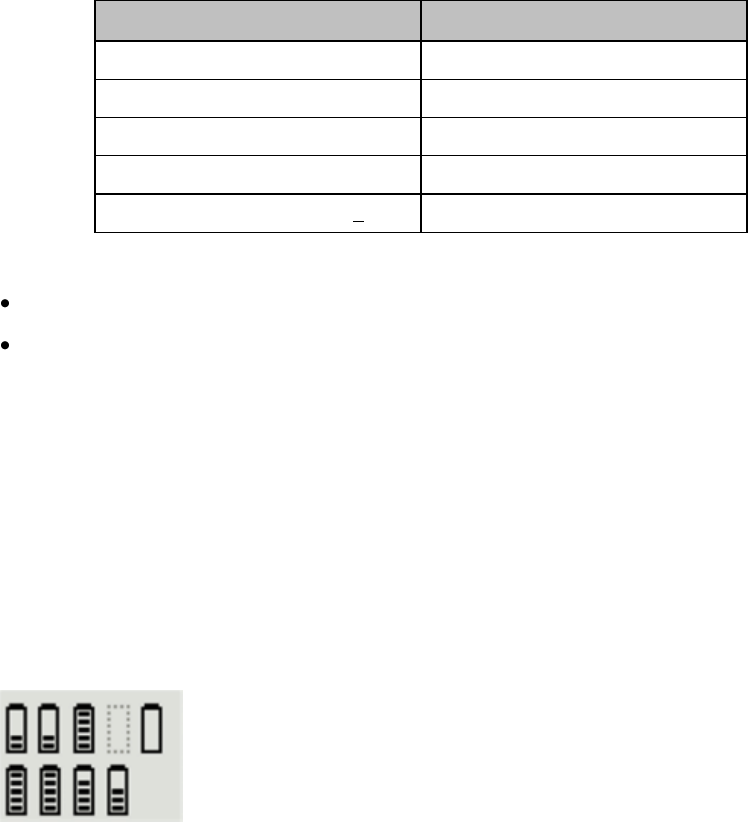
Charging Lithium-ion Rechargeable Batteries
Maintenance 14-9
If a battery is put on a charging station slot, the corresponding LED will
flash yellow until the battery's current state has been identified. Then a
beep is issued and the LED reflects the battery status as described in the
table below.
Status
LED
no battery on charger slot
off
battery put on charger slot
flashing yellow
battery not properly recognized, error
cyan
battery recognized, battery charging
yellow
battery recognized, battery full (>90%)
green
The AC Power / Error LED is
green when the charging station is connected to AC power
cyan during startup or to indicate a general charging station error
Note — Wiping of battery contacts with an alcohol solution after cleaning is
recommended.
Battery Status on the Charging Station Display
The IntelliVue CL Charging Station display provides a quick overview of
all the connected devices and their battery status. The screen is arranged in
the same layout as the charger slots.
Battery Lifetime Management
The lifetime of a li-ion battery depends on the frequency and duration of
use. When properly cared for, the useful life is approximately 4 years or 500
complete charge-discharge cycles, whichever comes first. In addition,
experience indicates that the incidence of failure may increase with battery
service life due to the accumulated stresses of daily use. We therefore
strongly recommend that li-ion batteries be replaced after 2 years or 500
complete charge-discharge cycles.
Draft Copy
Charging Lithium-ion Rechargeable Batteries
14-10 Maintenance
The age of a li-ion battery begins at the date of manufacture. The date of
manufacture is listed on the side of the battery.
Battery Disposal
Discharge the battery and insulate the terminals with tape before disposal.
Dispose of used batteries promptly and in accordance with local recycling
regulations.
Draft Copy
Safety Standards & Specifications 15-1
15. Safety Standards &
Specifications
This section describes the regulatory standards that the IntelliVue MX40
complies with, along with product and measurement specifications.
Regulatory Information .......................................................................... 15-2
Electromagnetic Compatibility .............................................................. 15-8
Battery Specifications ............................................................................ 15-14
Lithium-ion Battery Charge Time ....................................................... 15-17
Physical Specifications .......................................................................... 15-18
MX40 1.4 GHz Smart-Hopping Radio ................................................ 15-19
MX40 2.4 GHz Smart-Hopping Radio ................................................ 15-20
MX40 Short-Range Radio ..................................................................... 15-22
MX40 2.4GHz WLAN Radio ................................................................ 15-23
Environmental Specifications .............................................................. 15-25
Measurement Specifications ................................................................ 15-26
Draft Copy

Regulatory Information
15-2 Safety Standards & Specifications
Regulatory Information
Software Hazard Prevention
Potential hazards arising from errors in the software program have been
identified. Mitigations applied to reduce the associated risk of such hazards
are included as part of the Risk Management, Clinical Evaluation, and
Verification and Validation phases of the product’s development.
AC Power Source
The system is not intended for connection to the public mains as defined in
CISPR-11.
Industrie Canada Compliance (Canada)
This Class B ISM device complies with Canadian ICES-001.
Cet ISM de la classe B est conforme à la norme NMB-001 du Canada.
Safety Standards
The device complies with the following safety requirements for medical
electrical equipment:
EN 60601-1:1990 + A1:1993 + A2:1995 +A11:1993 +A12:1993 + A13:1996
General Requirements for Safety (with worldwide deviations, including
U.S. deviations)
CSA C22.2 #601.1:1992 Medical Electrical Equipment - General Safety
UL 60601-1 Medical Electrical Equipment - General Safety
UL 2054 Standards for Household and Commercial Batteries
EN 60601-1-1:2006 System Requirements
EN 60601-1-4:2000 Safety Requirements for Programmable Electronic
Medical Systems
EN 50371:2005 Low Power Electronic and Electronic Apparatus
Electromagnetic Exposure
EN ISO 9919:2005 Requirements for SpO2 Pulse Oximeters
EN ISO 10993-1:2003 Biocompatibility
EN ISO 10993-1:2003 Biocompatibility (for leadwires and pouch)
EN ISO 9919:2005 Pulse Oximeters
Draft Copy

Regulatory Information
Safety Standards & Specifications 15-3
IEC 60601-1-2:2001 Electromagnetic Compliance
IEC 60601-1-4:1999 +A1 Requirements for Programmable Electrical
Medical Systems
IEC 60601-1-6:2006 General requirements for basic safety and essential
performance - Collateral standard: Usability
IEC 60601-1-8:2006 General Requirements for Safety for Alarm Systems
IEC 60601-2-49:2001 Particular Requirements for Safety for Patient
Monitoring Equipment
IEC 60601-2-27:2005 Particular Requirements for Safety for
Electrocardiograph Monitoring Equipment
IEC 62133:2002 Safety Requirements for Portable Sealed Secondary Cells
(alkaline, lithium-ion)
AAMI EC 13:2007 Performance Standard, Cardiac Monitors
AAMI EC 53:1995 (R) 2001 ECG Cables/Leadwires (excluding 4.2.1)
Intended Use Statement
Intended for monitoring and recording of and to generate alarms for,
multiple physiological parameters of adults and pediatrics in a hospital
environment and during patient transport inside hospitals. Not intended
for home use. Intended for use by health care professionals.
Indications for Use
Indicated for use by health care professionals whenever there is a need for
monitoring the physiological parameters of patients. Intended for
monitoring and recording of, and to generate alarms for, multiple
physiological parameters of adults and pediatrics in hospital environments
and during transport inside hospitals.
Intended Uses of MX40
The MX40 is to be used primarily as a traditional telemetry medical device.
It connects to the IntelliVue Information Center by way of a wireless
network. When the MX40 is connected the IntelliVue Information Center
the IntelliVue Information Center provides the primary patient monitoring
and alarming function. The MX40 does not automatically provide local
monitoring or alarming when connected to the Information Center.
Draft Copy
Regulatory Information
15-4 Safety Standards & Specifications
The MX40 can provide time-limited local monitoring when it is not
connected to the wireless network.
Unlike a traditional bedside monitor which operates on AC power, the
MX40 is powered by battery and cannot provide continuous monitoring.
Authorized EU Representative
Philips Medizin Systeme Deutschland
Hewlett-Packard-Strasse 2
D 71034, Boeblingen
Germany
Patient Population
This device is not for use with infant or neonatal patients.
Use of the device is restricted to one patient at a time.
The components/accessories which come into contact with the patient’s skin
are in compliance with the relevant requirements of EN ISO 10993-1 for
Biocompatibility. The device is not designed for direct contact with the
patient’s skin. The accompanying pouch is the appropriate means for
holding the device.
Rx
Federal Law restricts this device to sale by or on the order of a physician.
Essential Performance
The IntelliVue MX40 provides Essential Performance (EP) under normal
operating conditions (includes EMC exposure) only as a complete Medical
Electrical System, consisting of the MX40, MPx companion monitor
(Optional), IntelliVue CL SpO2 and NBP Cableless Measurement
devices(Optional), IntelliVue Telemetry Network Infrastructure, and the
Information Center.
The System achieves its Essential Performance exclusively through alarm
generation at the IntelliVue Information Center and locally at the MX40,
based on configuration.
Draft Copy

Regulatory Information
Safety Standards & Specifications 15-5
The IntelliVue MX40 protects the patient from unacceptable immediate
clinical risk by generating specific Physiological Alarms when appropriate.
If the system cannot generate Physiological Alarms, then relevant Severe or
Hard-Level Technical Alarms (Inops) are created.
Risk Management Considerations
Warning
The MX40 operates exclusively via a wireless network connection,
therefore, it should not be used for primary monitoring in applications
where momentary loss of the ECG is unacceptable at the Information
Center. It sends ECG and optionally pulse oximetry data to the Information
Center, where the Information Center displays real-time patient data,
provides alarm annunciation, data storage and review applications. The
ECG waveform data, alarms and optionally SpO2 can always be viewed on
the MX40 regardless of the connection to the Information Center.
Smart Hopping technology alleviates most of the problems associated with
legacy telemetry technologies. Reception problems are less frequent,
because Smart Hopping avoids interference and moves to a different access
point if the signal strength is too low. The level of radio frequency activity
is always fluctuating in the environment. If the level becomes high enough
to significantly interfere with transceiver operation, the system responds by
moving to another "cleaner" area where there is less activity.
Dropouts
Because the MX40 operates exclusively via a wireless network connection,
under certain frequency conditions dropouts can occur. Dropouts result
from a weak signal or RF interference, and appear on the waveform when
the signal "drops" to the bottom of the channel for a minimum of 200 ms. If
dropouts are frequent enough to affect the heart rate count, the "Cannot
Analyze ECG" or "Cannot Analyze ST" technical alarm occurs. If there are
enough dropouts to cause disassociation/reassociation with the Information
Center, events in the Clinical Review application can reflect loss of data for
up to 1 minute in the worst case.
Draft Copy
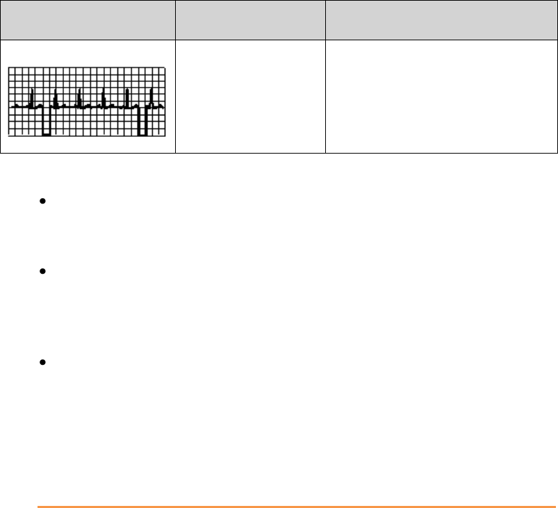
Regulatory Information
15-6 Safety Standards & Specifications
Problem
Cause
Remedy
Dropouts
Low signal strength
RF interference
See "Signal Strength" below.
See "Radio Frequency Interference"
below.
Monitoring Considerations
Patient should be restricted to the designated coverage area. Monitoring
performance will degrade if patients go outside the radius of coverage
of the receiving wireless network.
A patient location strategy is critical to a telemetry system. If a
life-threatening event occurs, the clinician must be able to locate the
patient quickly. The importance of this increases as the coverage area
increases.
Frequency management is the responsibility of the hospital. Philips
Healthcare has no control over the RF environment in the hospital. If
interference exists at the operating frequencies of the telemetry
equipment, telemetry performance will be affected. Careful selection of
frequencies for all wireless devices used within a facility (transceivers,
other wireless medical devices, etc.) is important to prevent interference
between them.
Caution
IEC/ANSI/AAMI 80001-1:2010
Philips recognizes the importance of a safe and effective network that meets
both the business needs of a healthcare facility, IT networking
requirements, and the clinical functionality. Philips supports the IEC
80001-1 standard in regards to working as a partner with a healthcare
organization in the design, implementation, and management of the
Medical IT-Network to properly provision and support not only Philips
devices, but all the devices using the network. Applying the principles of
risk management to hospital frameworks is highly encouraged.
When operating the MX40 on a Customer Supplied Clinical Network,
Philips strongly encourages our customers to perform risk management of
their Medical IT-Network infrastructure in accordance with IEC 80001.
Draft Copy

Regulatory Information
Safety Standards & Specifications 15-7
If the MX40 experiences loss of network connectivity, technical alerts at the
Information Center ("No Signal") and at the MX40 ("No Central Monitor")
will occur. The MX40 will also automatically revert to local monitor mode
which activates display of patient data on the MX40 – however, when in
this state, battery life will be shortened.
Draft Copy

Electromagnetic Compatibility
15-8 Safety Standards & Specifications
Electromagnetic Compatibility
Medical electrical equipment can either generate or receive electromagnetic
interference. This product has been evaluated for electromagnetic
compatibility (EMC) with the appropriate accessories according to IEC
60601-1-2:2001, the international standard for EMC for medical electrical
equipment. This IEC standard has been adopted in the European Union as
the European Norm, EN 60601-1-2:2001.
Radio frequency (RF) interference from nearby transmitting devices can
degrade performance of the product. Electromagnetic compatibility with
surrounding devices should be assessed prior to using the product.
Fixed, portable, and mobile radio frequency communications equipment
can also affect the performance of medical equipment. See your service
provider for assistance with the minimum recommended separation
distance between RF communications equipment and the product.
The cables, sensors/transducers, and other accessories for which compliance
is claimed are listed in the Service and User documentation accompanying
the product.
Warnings
The use of accessories, transducers and cables other than those specified
in the product service and user documentation can result in increased
electromagnetic emissions or decreased immunity of the product.
Short-range radio connections are subject to interruption due to
interference from other radio sources in the vicinity, including
microwaves, bluetooth devices, and DECT phones. Outside the
frequency band and 5% above and below, i.e. the exclusion band
according to IEC 60601-1-2, the short-range radio connection is immune
up to 3V/m in the frequency range from 80MHz to 2.5 GHz. Depending
on the strength and duration of the interference, the interruption may
occur for an extended period. Any interruption of the signal due to
interference, moving out of range, or for other reasons is indicated with
a Tele Disconnected INOP message.
The product should not be used next to or stacked with other
equipment. If you must stack the product, you must check that normal
operation is possible in the necessary configuration before the product
is used on patients.
Draft Copy

Electromagnetic Compatibility
Safety Standards & Specifications 15-9
Reducing Electromagnetic Interference
The MX40 and associated accessories can be susceptible to interference
from other RF energy sources and continuous, repetitive, power line bursts.
Examples of other sources of RF interference are other medical electrical
devices, cellular products, information technology equipment, and
radio/television transmission. If interference is encountered, as
demonstrated by artifact on the ECG or dramatic variations in physiological
parameter measurement values, attempt to locate the source. Assess the
following:
Is the interference due to misplaced or poorly applied electrodes or
sensors? If so, re-apply electrodes and sensors correctly according to
directions in Chapter 6.
Is the interference intermittent or constant?
Does the interference occur only in certain locations?
Does the interference occur only when in close proximity to certain
medical electrical equipment?
Once the source is located, attempt to attenuate the interference by
distancing the MX40 from the source as much as possible. If assistance is
needed, contact your local service representative.
Restrictions for Use
Artifact on ECG and other physiological waveforms caused by
electromagnetic interference should be evaluated by a physician or
physician authorized personnel to determine if it will negatively impact
patient diagnosis or treatment.
Electromagnetic Compatibility (EMC) Specifications
Take special precautions regarding electromagnetic compatibility (EMC)
when using medical electrical equipment. You must operate your
monitoring equipment according to the EMC information provided in this
book. Portable and mobile radiofrequency (RF) communications equipment
can affect medical electrical equipment.
Accessories Compliant with EMC Standards
All accessories listed in the accessories section comply, in combination with
the MX40, with the requirements of IEC 60601-1-2:2001 + A1:2004.
Draft Copy

Electromagnetic Compatibility
15-10 Safety Standards & Specifications
Warning
Using accessories other than those specified may result in increased
electromagnetic emission or decreased electromagnetic immunity of the
monitoring equipment.
Electromagnetic Emissions
Emissions Test
Compliance
Avoiding Electromagnetic
Interference
Radio Frequency (RF)
emissions
Group 1
TheMX40 uses RF energy only for its
internal function. Therefore, its RF
emissions are very low and are not likely
to cause any interference in nearby
electronic equipment.
RF emissions CISPR
11
Class B
The MX40 is suitable for use in all
establishments.
Harmonized emissions
Not Applicable
Device is battery powered only
Voltage
fluctuations/Flicker
emissions
IEC 61000-3-3
Not Applicable
Electromagnetic Immunity
The MX40 is suitable for use in the specified electromagnetic environment.
The user must ensure that it is used in the appropriate environment as
described below.
Immunity Test
IEC 60601-1-2 Test
Level
Compliance Level
Electromagnetic
Environment Guidance
Electrostatic discharge
(ESD)
IEC 61000-4-2
±6 kV contact
±8 kV air
±6 kV contact
±8 kV air
Floors should be wood, concrete,
or ceramic tile. If floors are
covered with synthetic material,
the relative humidity should be at
least 30%.
Power frequency (50/60
Hz) magnetic field
IEC 61000-4-8
3 A/m
3 A/m
Power frequency magnetic fields
should be a t levels characteristic
of a typical location in a typical
commercial and/or hospital
environment
Draft Copy

Electromagnetic Compatibility
Safety Standards & Specifications 15-11
Recommended Separation Distance
Warning
The MX40, equipped with a wireless network interface, intentionally
receives RF electromagnetic energy for the purpose of its operation.
Therefore, other equipment may cause interference, even if that other
equipment complies with CISPR emission requirements.
In the following table, P is the maximum output power rating of the
transmitter in watts (W) according to the transmitter manufacturer and d is
the recommended separation distance in meters (m).
Portable and mobile RF communications equipment should be used no
closer to any part of the MX40, including cables, than the recommended
separation distance calculated from the equation appropriate for the
frequency of the transmitter.
Field strengths from fixed RF transmitters, as determined by an
electromagnetic site survey, should be less than the compliance level in
each frequency range.
Interference may occur in the vicinity of equipment marked with this
symbol:
Immunity Test
IEC 60601-1-2 Test
Level
Compliance Level
Electromagnetic
Environment Guidance
Conducted RF
IEC 61000-4-6
3 Vrms
150 kHz to 80 MHz
3 VRMS
Recommended separation
distance:
d = 1.2√P
Radiated RF IEC
61000-4-3
3 V/m
80 MHz to 2.5 GHz
3 V/m
Recommended separation
distance:
80 MHz to 800 MHz
d = 1.2√P
800 MHz to 2.5 GHz
d = 2.3√P
Draft Copy

Electromagnetic Compatibility
15-12 Safety Standards & Specifications
Field strengths from fixed transmitters, such as base stations for radio
(cellular, cordless) telephones and land mobile radios, amateur radio, AM
and FM radio broadcast and TV broadcast cannot be predicted theoretically
with accuracy. To assess the electromagnetic environment due to fixed RF
transmitters, an electromagnetic site survey should be considered. If the
measured field strength in the location in which the monitor is used
exceeds the applicable RF compliance level above, the MX40 should be
observed to verify normal operation. If abnormal performance is observed,
additional measures may be necessary, such as reorienting or relocating the
monitor.
These guidelines may not apply in all situations. Electromagnetic
propagation is affected by absorption and reflection from structures,
objects, and people.
The MX40 is intended for use in an electromagnetic environment in which
radiated RF disturbances are controlled. The customer or user of the
monitor can help prevent electromagnetic interference by maintaining a
minimum distance between portable and mobile RF communications
equipment and the monitor as recommended below, according to the
maximum output power of the communications equipment.
In the following table, P is the maximum output power rating of the
transmitter in watts (W) according to the transmitter manufacturer and d is
the recommended separation distance in meters (m).
Frequency of
Transmitter
150 kHz to 80 MHz
80 MHz to 800 MHz
800 MHz to 2.5 GHz
Equation
d = 1.2√P
d = 1.2√P
d = 2.3√P
Rated max. output
power of transmitter
Separation distance
Separation distance
Separation distance
0.01 W
0.1 m
0.1 m
0.2 m
0.1 W
0.4 m
0.4 m
0.7 m
1 W
1.2 m
1.3 m
2.3 m
10 W
3.8 m
3.8 m
7.3 m
100 W
12.0 m
12.0 m
23.0 m
Draft Copy
Electromagnetic Compatibility
Safety Standards & Specifications 15-13
Electrosurgery Interference/Defibrillation/Electrostatic
Discharge
The equipment returns to the previous operating mode within 10 seconds
without loss of any stored data. Measurement accuracy may be temporarily
decreased while performing defibrillation. This does not affect patient or
equipment safety. Do not expose the equipment to x-ray or strong magnetic
fields (MRI). The MX40 is not for use during electrosurgery.
Restart Time
After power interruption, an ECG wave will be shown on the display after
30 seconds maximum.
Draft Copy

Battery Specifications
15-14 Safety Standards & Specifications
Battery Specifications
Battery Life
The battery life specifications listed below are based on the use of three
Duracell MN 1500 batteries. Battery life for other brands may differ.
Telemetry Mode
Networked
(Display Off)
Battery Life
(1.4GHz
p/n 865350)
Battery Life
(2.4GHz
p/n 865351)
ECG Only (only one radio
active)
24.9 hours
24.7 hours
ECG/SpO2 Continuous
(using legacy SpO2
cable/sensors. Only one
radio active.)
11.2 hours
8.9 hours
ECG/SpO2 Manual
In this mode battery life is dependent on the
usage rate and will range between the ECG
Only battery life and the ECG/SpO2
Continuous battery life.
Monitor Mode
Networked
(Display On)
Battery Life
(1.4GHz
p/n 865350)
Battery Life
(2.4GHz
p/n 865351)
ECG Only (only one radio
active)
11 hours
7.7 hours
ECG/SpO2 Continuous
(using legacy SpO2
cable/sensors. Only one
radio active.)
5.3 hours
2.9 hours
ECG/SpO2 Manual
In this mode battery life is dependent on the
usage rate and will range between the ECG
Only battery life and the ECG/SpO2
Continuous battery life.
Monitor Mode
Non-networked
(Display On)
Battery Life
(1.4GHz
p/n 865350)
Battery Life
(2.4GHz
p/n 865351)
ECG Only (only one radio
active)
6.8 hours
7.3 hours
ECG/SpO2 Continuous
(using legacy SpO2
cable/sensors. Only one
radio active.)
4.7 hours
4.6 hours
Draft Copy

Battery Specifications
Safety Standards & Specifications 15-15
Monitor Mode
Non-networked
(Display On)
Battery Life
(1.4GHz
p/n 865350)
Battery Life
(2.4GHz
p/n 865351)
ECG/SpO2 Manual
In this mode battery life is dependent on the
usage rate and will range between the ECG
Only battery life and the ECG/SpO2
Continuous battery life.
The battery life specifications listed below are based on the use of the
Philips Rechargeable Lithium-ion battery.
Telemetry Mode
Networked
(Display Off)
Battery Life
(1.4GHz
p/n 865350)
Battery Life
(2.4GHz
p/n 865351)
Battery Life
(WLAN
p/n 865352)
ECG Only (only one radio
active)
26.1 hours
25.1
25 hours
ECG/SpO2 Continuous
(using legacy SpO2
cable/sensors. Only one
radio active.)
15.6 hours
14.1
15 hours
ECG/SpO2 Manual
In this mode battery life is dependent on the usage rate and will
range between the ECG Only battery life and the ECG/SpO2
Continuous battery life.
Monitor Mode
Networked
(Display On)
Battery Life
(1.4GHz
p/n 865350)
Battery Life
(2.4GHz
p/n 865351)
Battery Life
(WLAN
p/n 865352)
ECG Only (only one radio
active)
11 hours
10.4 hours
11 hours
ECG/SpO2 Continuous
(using legacy SpO2
cable/sensors. Only one
radio active.)
8 hours
7.8 hours
8 hours
ECG/SpO2 Manual
In this mode battery life is dependent on the usage rate and will
range between the ECG Only battery life and the ECG/SpO2
Continuous battery life.
Monitor Mode
Non-networked
(Display On)
Battery Life
(1.4GHz
p/n 865350)
Battery Life
(2.4GHz
p/n 865351)
Battery Life
(WLAN
p/n 865352)
ECG Only (only one radio
active)
13 hours
10.4 hours
12 hours
ECG/SpO2 Continuous
(using legacy SpO2
cable/sensors. Only one
radio active.)
8.8 hours
7.8 hours
8.5 hours
Draft Copy

Battery Specifications
15-16 Safety Standards & Specifications
Monitor Mode
Non-networked
(Display On)
Battery Life
(1.4GHz
p/n 865350)
Battery Life
(2.4GHz
p/n 865351)
Battery Life
(WLAN
p/n 865352)
ECG/SpO2 Manual
In this mode battery life is dependent on the usage rate and will
range between the ECG Only battery life and the ECG/SpO2
Continuous battery life.
Note — Use of the Short-range radio can reduce battery life by 25%.
Note — The battery capacity of re-chargeable batteries degrades over time
and number of recharge cycles. Toward the end of its useful life, the battery
capacity may be reduced by 25-30%. If this reduced battery life is
unacceptable based on your use model, Philips recommends replacing the
rechargeable battery sooner.
Nominal Current
Operating Mode
Nominal Current
(p/n 865350)
Nominal Current
(p/n 865351)
Nominal Current
(p/n 865352)
ECG Only (Display
inactive)
67 mA @ 3.6V
67 mA @ 3.6V
70 mA @ 3.6V
ECG/SpO2 Continuous
(Display inactive)
136 mA @ 3.6V
136 mA @ 3.6V
140 mA @ 3.6V
Draft Copy

Lithium-ion Battery Charge Time
Safety Standards & Specifications 15-17
Lithium-ion Battery Charge Time
Definition
Charging Method
Charge
Time
Battery pack charge
time from 90%
depletion state
The Lithium-ion Battery Pack is charged on
a separate external charging station. It
must be removed from the MX40 to
charge.
6.5 hours
Draft Copy
Physical Specifications
15-18 Safety Standards & Specifications
Physical Specifications
Parameter
Specification
Height
126.8 mm (4.99 in)
Width
69.9 mm (2.75 in)
Depth
31.5 mm (1.24 in)
Weight
Without batteries, includes
SpO2 and Short-range radio
With 3 AA batteries, includes
SpO2 and Short-range radio
With lithium-ion battery,
includes SpO2 and Short -range
radio
1.4 GHz - 240 g (8.5 oz)
2.4 GHz - 215 g (7.6 oz)
WLAN - 206 g (7.3 oz)
1.4 GHz - 324 g (11.4 oz)
2.4 GHz - 298 g (10.5 oz)
WLAN - 292 g (10.3 oz)
1.4 GHz - 314 g (11.1 oz)
2.4 GHz - 289 g (10.2 oz)
WLAN - 274 g (9.7 oz)
Display
Type
View Area
Resolution
Backlight
ECG Display Sector Size
(height)
ECG Display Sweep Speed
Resp Display Sweep Speed
2.8" QVGA Color LCD
43.2mm x 57.6 mm (1.70" x 2.26")
240 x 320
White LED
13.5mm (portrait), 9.9mm (landscape)
10mm/s with 4.32 sec of viewable ecg
data (portrait), 10mm/s with 5.76 sec of
viewable ecg data (landscape)
2.5mm/s with 17.28 sec of viewable resp
data (portrait) 2.5mm/s with 23.04 sec of
viewable resp data (landscape).
Alarm Signal Sound Pressure
Level
40dB(A) - 70dB(A)
Draft Copy

MX40 1.4 GHz Smart-Hopping Radio
Safety Standards & Specifications 15-19
MX40 1.4 GHz Smart-Hopping Radio
Parameter
Specification
Frequency Ranges
Bands: 1395-1400 MHz and 1427-1432 MHz
Channel Spacing: 1.6 MHz
RF Output Power (existing
systems)
8 dBm +2/-1.5 dB (4.5 mW to 10 mW), into
antenna load
Radio Frequency Accuracy
during normal operation
<+60/-100 KHz relative to channel frequency,
includes temperature compensation and aging
effects
Modulation Type
GFSK (1M40Q7D)
Out of Band Spurious
Emission Levels:
<= 1394 MHz, >= 1401
MHz
<= 1428 MHz, >= 1433
MHz
<-41 dBm in 1 MHz bandwidth for FCC limit
Occupied bandwidth as
defined by power in 99%
BW
< +/- 800 KHz
1.4GHz WMTS (US only)
This device complies with Part 15 of the FCC Rules. Operation is subject to
the condition that this device does not cause harmful interference.
Operation of this equipment requires the prior coordination with a
frequency coordinator designated by the FCC for the Wireless Medical
Telemetry Service.
Draft Copy

MX40 2.4 GHz Smart-Hopping Radio
15-20 Safety Standards & Specifications
MX40 2.4 GHz Smart-Hopping Radio
Parameter
Specification
Frequency Range
ISM Band: 2400 - 2483.5 MHz
Channel Assignment
48 radio channels assigned from 2401.056 MHz
- 2482.272 MHz
Channel Spacing: 1.728 MHz
RF Output Power
FCC: Channels 0-46 -17 dBm +/- 1 dB (40 mW
to 63 mW, nominal 50 mW), into antenna load.
Channel 47 only - 15 dBm +/- 1 dB.
ETSI: 12 dBm +/- 1 dB (13 mW to 20 mW,
nominal 16 mW), into antenna load
ARIB: 13.5 dBm +/- 1 dB (18 mW to 28 mW,
nominal 22 mW), into antenna load
Radio Frequency Accuracy
during normal operation
<+ 60 /- 100 KHz relative to channel frequency,
includes temperature compensation and aging
effects
Modulation Type
GFSK, Gaussian Frequency Shift keying
(1M40Q7D)
Modulation Bandwidth
Typically 1.4 MHz (20 dB Bandwidth)
Typically 980 KHz (6 dB Bandwidth)
Out of Band Spurious
Emission Levels
Meets ETSI, RS210, FCC, ARIB standards
2.4 GHz ISM
FCC and Industry Canada Radio Compliance: This device complies with
Part 15 of the FCC Rules and RSS-210 of Industry Canada. Operation is
subject to the following two conditions: (1) this device may not cause
harmful interference, and (2) this device must accept any interference
received, including interference that may cause undesired operation. Any
changes or modifications to this equipment not expressly approved by
Philips Medical Systems may cause harmful radio frequency interference
and void your authority to operate this equipment.
Draft Copy
MX40 2.4 GHz Smart-Hopping Radio
Safety Standards & Specifications 15-21
The radio device used in this product is in compliance with the essential
requirements and other relevant provisions of Directive 1999/5/EC (Radio
Equipment and Telecommunications Terminal Equipment Directive). Class
2 radio equipment. Member states may apply restrictions on putting this
device into service or placing it on the market. This product is intended to
be connected to the Publicly Available Interfaces (PAI) and used
throughout the EEA.
This ISM device complies with Canadian ICES-001. Cet appareil ISM est
conforme a la norme NMB-001 du Canada.
Draft Copy

MX40 Short-Range Radio
15-22 Safety Standards & Specifications
MX40 Short-Range Radio
Parameter
Specification
Frequency Ranges
ISM Band: 2400-2483.5MHz
Radio Channel assignment
16 Radio Channel assigned, Fc= 2405 +5*(k-11)MHz,
k=11,12,…,26
Frequency Control
Configured via the bedside monitor or the Information
Center depending on use model.
RF Output Power
-1.5 to -4.5 dBm +2/-3dB (0.7 mW to 0.3 mW), into
Antenna load.
MX40 Frequency Accuracy
during normal operation
<+/-40ppm, includes temperature compensation &
aging effects
Modulation Type
Direct Sequence Spread Spectrum (DSSS), O-QPSK
with half sine pulse shaping modulation (1M40Q7D)
Modulation Bandwidth
>500KHz, typically +/-950KHz (6dB Bandwidth),
typically +/-1.4MHz (20dB Bandwidth)
Draft Copy

MX40 2.4GHz WLAN Radio
Safety Standards & Specifications 15-23
MX40 2.4GHz WLAN Radio
The MX40 2.4GHz/5.6GHz WLAN Radio conforms to the 802.11 a/b/g
standard operating in the 2.4GHz and 5.6GHz ISM bands.
Note — For the MX40 WLAN device, Part Number 865352, use of the
MX40's Short-range Radio is only supported when operating with 802.11a
(5.6GHz band).
The Radio characteristics are defined below.
WLAN Radio RF Specs
Specification
802.11b
Technology
IEEE 802.11 b
Frequency Range
2.4 to 2.4835GHz
Transmitter Power
14 to 17 dBm into antenna load (RMS power)
Modulation
CCK (Complementary Code Keying)
Occupied Bandwidth, 99%
<-22 MHz
802.11g
Technology
IEEE 802.11 g
Frequency Range
2.4 to 2.4835GHz
Transmitter Power
12 to 15 dBm into antenna load (RMS power)
Occupied Bandwidth, 99%
<-22 MHz
Modulation Type
OFDM (Orthogonal Frequency Division
Multiplex)
Frequency Bands (802.11 b/g)
FCC, RS210, ETSI
Japan{ARIB},China, AU/NZ: 2.400 –
2.4835GHz
Out of Band Emissions (802.11
b/g)
Meets ETSI, RS210, FCC, ARIB, AU/NZ
standards
802.11a
Technology
IEEE 802.11 a
Frequency Power
5.15 to 5.825GHz
Transmitter Power
12 to 14 dBm into Antenna load (RMS power)
Occupied Bandwidth
≤ 18 MHz
Modulation
DSSS : OFDM (Orthogonal Frequency
Division Multiplex)
Draft Copy

MX40 2.4GHz WLAN Radio
15-24 Safety Standards & Specifications
WLAN Radio RF Specs
Specification
Frequency Bands (802.11a)
FCC, RS210: 5.15 ~ 5.25Ghz, 5.25 ~
5.35Ghz, 5.42 ~ 5.725Ghz, 5.725 ~ 5.825Ghz
(excluding 5.6 ~5.65GH
ETSI, AU/NZ: 5.15~ 5.35Ghz, 5.47 ~
5.725Ghz Japan, ARIB: 5.150 – 5.250GHz,
5.25 – 5.35GHz, 5.470 – 5.725GHz,
China: 5.725 ~5.825Ghz
Out of Band Emissions
(802.11a)
Meets ETSI, RS210, FCC, ARIB, AU/NZ
standards
FCC and Industry Canada Radio Compliance
This device complies with Part 15 of the FCC Rules and RSS-210 of Industry
Canada. Operation is subject to the following two conditions: (1) this device
may not cause harmful interference, and (2) this device must accept any
interference received, including interference that may cause undesired
operation. Any changes or modifications to this equipment not expressly
approved by Philips Medical Systems may cause harmful radio frequency
interference and void your authority to operate this equipment.
The maximum antenna gain permitted (for devices in the 5250-5350
MHz and 5470-5725 MHz bands) complies with the e.i.r.p. limits as
stated in RSS-210.
The maximum antenna gain permitted (for devices in the 5725-5825
MHz bands) complies with the e.i.r.p. limits specified for point-to-point
operation as stated in RSS-210.
The device for band 5150-5250 MHz is only for indoor usage to reduce
potential for harmful interference to co-channel mobile satellite systems.
Caution
High power radars are allocated as primary users of 5250-5350 MHz and
5650-5850 MHz. These radars could cause interference and/or damage to
LE-LAN devices.
Draft Copy

Environmental Specifications
Safety Standards & Specifications 15-25
Environmental Specifications
Parameter
Specification
Temperature
Operating
Storage
0 to 37o C (32 to 99o F)
-30o C to 50o C (-22o F to 122o F) without batteries
12o C to 35o C (53.6o F to 95oF) with Single-Patient-Use
leadsets
Humidity
Operating
Storage
< 95% RH at 37o C (98.6o F) non-condensing
< 90% RH at 50o C (122o F) without batteries
Altitude
Operating &
Non-operating
Barometric
Pressure
3,000 m (9,842 ft)
72kPa (537 mmHg)
Draft Copy

Measurement Specifications
15-26 Safety Standards & Specifications
Measurement Specifications
ECG
Parameter
Specification
ECG channel transmitted
Leads
3 electrodes
Channel #1 = I, II, or III
5 electrodes
Channel #1 = II
Channel #2 = III
Channel #3 = MCL
5 electrodes, EASI
Channel #1 = Va-i
Channel #2 = Va-s
Channel #3 = Ve-s
6 electrodes
Channel #1= II
Channel #2 = III
Channel #3 = MCLa
Channel #4 = MCLb
Resolution
5 V
ECG Input
Differential, defibrillator protected against 360
joules discharge into a 100 ohm load
Input Impedance
> 5 megohms (@ 10 Hz
Input Dynamic Range
+/- 9 mV
DC Offset Range
+/- 320 mV
CMRR
> 90 dB @ 50, 60 Hz
Bandwidth +/- 3 dB
0.05 to 40 Hz
Gain Accuracy
+/- 5% at 25 oC (77 oF)
Noise Referred to ECG
Input (Peak-to-Peak)
AAMI: 30 V (as per AAMI EC 13)
Lead Wires
3, 5 or 6-wire patient cable compatible with
IntelliVue Patient Monitor, AAMI/IEC color codes
Time to baseline recovery
from Defibrillator
AAMI: 5 s max (until ECG wave is on display but
not yet centered, monitoring bandwidth)
Draft Copy

Measurement Specifications
Safety Standards & Specifications 15-27
Parameter
Specification
Pacer Rejection
Performance
(Pace pulses with no
tails).
Positive pacers1
Amplitude Width
+2 to +700 mV 0.1, 0.2, 0.5 and 1.0 ms
+2 to +500 mV 1.5 ms
+2 to +400 mV 2 ms
Negative pacers1
Amplitude Width
-2 to -700 mV 0.1, 0.2, 0.5 and 1.0 ms
-2 to -500 mV 1.5 ms
-2 to -400 mV 2 ms
1 Philips does not claim, verify, or validate support
for all available pacemakers.
EMC Performance Limits,
radiated immunity
Meets Essential Performance.
ECG Patient Cable
Disconnection Safety
All ECG connections are patient safe within 750
msec of patient cable removal, with patient leakage
current <10 Exception: Leadset detection pins
are protected mechanically to prevent patient
contact.
ECG Performance Disclosure/Specifications
Characteristic
Performance Disclosure/Specification (in
italics)
Heart Rate Averaging Method
Two different methods are used:
Normally, heart rate is computed by averaging the 12
most recent RR intervals.
If each of 3 consecutive RR intervals are greater than
1200 milliseconds (i.e. rate less than 50 b/min) for adult
and pediatric patients, then the 4 most recent RR
intervals are averaged to compute the HR.
Heart Rate Meter Accuracy and Response
to Irregular Rhythm
Provides correct heart rates (80, 60, 120, 90 b/min) using
test waveforms as indicated in ANSI/AAMI EC13
Sec. 4. 1. 2. 1 (e).
Response Time of Heart Rate Meter to
Change in Heart Rate
For a rate increase, the average time to reach the specified
heart rate using test waveforms as indicated in ANSI/AAMI
EC13 Sec. 4. 1. 2. 1 (f) is 10 seconds. For a rate drop, the
average time is 7 seconds.
Draft Copy

Measurement Specifications
15-28 Safety Standards & Specifications
Characteristic
Performance Disclosure/Specification (in
italics)
Time to Alarm for Tachycardia
The ranges of time to alarm using test waveforms as
indicated in ANSI/AAMI EC13 Sec. 4 1. 2. 1 (g) are 4 to 5
seconds.
Pacemaker Pulse Rejection Capability
Rejects pace pulses using test waveforms as indicated in
ANSI/AAMI EC13 Sec. 4. 1. 4.1 (with amplitude from +/- 2
to +/- 700 mV, width from 0.1 to 2.0 ms).
Range and Accuracy of Heart Rate Meter
Meets the ANSI/AAMI EC13 Section 4.2.7 recommended
minimum range and accuracy.
Heart rate range is 15 - 300 b/min for adults patients and
15-350 b/min for pediatric patients with accuracy of 1% of
the range. (Note: for rates equal to or less than 15, the
displayed heart rate is 0).
Alarm Limit Range
Meets the ANSI/AAMI EC13 Section 4.2.8.1 standard.
Lower alarm limit is 15 -295. Upper alarm limit is 20 - 300.
Resolution of Alarm Limit Settings
Meets the ANSI/AAMI EC13 Section 4.2.8.2 standard. The
resolution is 5 b/min.
Alarm Limit Accuracy
Meets the ANSI/AAMI EC13 Section 4.2.8.3 standard.
Error less than ± 10% or ± 5b/min
Time to Alarm for Cardiac Standstill
Meets the ANSI/AAMI EC13 Section 4.2.8.4 standard:
maximum alarm time <10 seconds, using the test
waveforms as indicated.
Time to Alarm for Low Heart Rate
Meets the ANSI/AAMI EC13 Section 4.2.8.5 standard:
maximum alarm time <10 seconds, using the test
waveforms as indicated.
Time to Alarm for High Heart Rate
Meets the ANSI/AAMI EC13 Section 4.2.8.6 standard:
maximum alarm time <10 seconds, using the test
waveforms as indicated.
Alarm Silencing
The time required for reactivation of a latched, silenced
alarm is 3 minutes
ECG Waveform Display Time Base
Accuracy
Meets the ANSI/AAMI EC13 Section 4.2.9.6 standard:
maximum error = +/-10%.
Channel Width
Meets the ANSI/AAMI EC13 Section 4.2.9.7(a) standard:
minimum = 30mm.
Trace Width
Meets the ANSI/AAMI EC13 Section 4.2.9.7(b) standard:
maximum = 1.0mm.
Aspect Ratio
Meets the ANSI/AAMI EC13 Section 4.2.9.7(f) standard: 0.4
+ 0.08 s/mV.
Input Signal Reproduction Accuracy:
Overall Error
Meets the ANSI/AAMI EC13 Section 4.2.9.8(a) standard:
maximum = +/- 20%.
Frequency Response: Sinusoidal
Meets the ANSI/AAMI EC13 Section 4.2.9.8(b) standard:
0.67 to 40 Hz
(3 db down).
Draft Copy

Measurement Specifications
Safety Standards & Specifications 15-29
Characteristic
Performance Disclosure/Specification (in
italics)
Frequency Response: Triangular
Meets the ANSI/AAMI EC13 Section 4.2.9.8(b) standard: 0
to 25% reduction.
Impulse Response:
(for waves marked with ST bandwidth)
Meets the ANSI/AAMI EC13 Section 4.2.9.8(c) standard:
displacement maximum = 0.1 mV; slope
maximum = 0.30 mV/s.
Pacemaker Pulse Display Capability
Meets the ANSI/AAMI EC13 Section 4.2.9. 12 standard:
minimum = 0.2 mV RTI.
Tall T-Wave Rejection Capability
Meets AAMI standard:
0.5 – 40 BW: HR of 80bpm at all T-wave amplitudes
0.05 – 40 BW: HR of 80bpm at all T-wave amplitudes
Respiration
Parameter
Specification
Leads Used for Measurement
RA, LL (standard) or I, A (EASI)
Range
Adult/Pedi: 0 to 120 rpm
Bandwidth
0.3Hz to 2.5Hz (-6dB)
Noise
Less than 25 mOhm (rms) referred to the
input
Calibration Signal
Signal: 1 Ohm p-p; Accuracy: +/- 20%
Respiration Rate Resolution
1 rpm
Respiration Accuracy
+/- 1 rpm for 0-120 rmp
Auxiliary Current, Respiration Excitation
Signal
< 470 uA rms @48KHz, sinusoidal waveform
Respiration Alarm
Alarm
Range
Delay
High
Adult/Pediatric: 10 to 100 rpm
≤ 15 seconds
Low
Adult/Pediatric: 0 to 95 rpm
for limits from 0 to 20 rpm: max. 4 seconds
for limits above 20 rpm: max. 15 seconds
Apnea Alarm
10 to 40 seconds
Incremental delay 5 seconds max.
Draft Copy

Measurement Specifications
15-30 Safety Standards & Specifications
FAST SpO2
Parameter
Specification
SpO2 Measurement
Range (Calibration and
Display)
0 to 100%
SpO2 Accuracy
See table following.
SpO2 Resolution
1%
SpO2 Numerics -
Averaging
5 - 20 seconds (default = 10 seconds)
Note—The update rate for the SpO2 pulse oximetry value and pulse rate is
typically 1 second. This can be extended to a max. 60 s when NBP is
measured on the same limb, with a corresponding INOP message after a
max. of 30 s, indicating that the displayed values are not current values.
The effect of SpO2 pulse oximetry on data averaging is internally controllable
by the patient worn monitorMX40, with no user controls.
SpO2 & Pulse Numerics -
Update Rate
Transmitted once per second.
Note—The update rate for the SpO2 pulse oximetry value and pulse rate is
typically 1 second. This can be extended to a max. 60 s when NBP is
measured on the same limb, with a corresponding INOP message after a
max. of 30 s, indicating that the displayed values are not current values.
Pleth Wave- Sampling
Rate
125 sps
Technical Alarms
(INOPs)
Triggered if the sensor is disconnected, if a pulse is not detected, if the signal
is noisy, if light interference is detected, if the sensor is defective, if the
measurement is erratic, or if the module is malfunctioning
Wavelength Range
500 to 1000 nm
Note—Information about wavelength range can be especially useful to
clinicians (e.g., clinicians performing photodynamic therapy).
Pulse Rate Measurement
(available only with
Continuous SpO2)
Range: 30 to 300 bpm
Accuracy: +/- 2%
Resolution: 1 bpm
Draft Copy

Measurement Specifications
Safety Standards & Specifications 15-31
Parameter
Specification
Display of SpO2
numerics
SpO2 values are displayed as xxx % SpO2 to meet ISO 9919.
Emitted Light Energy
< 15 mW
SpO2 Sensor Accuracy
Type
Description
Model Number
Accuracy %
Arms
(70-100%
Range)
Reusable Sensors
Adult Finger, 2m cable
M1191B
2.0
Adult Finger, 3m cable
M1191BL
2.0
Adult Finger, 0.45m cable
M1191T
3.0
Pediatric, Small Adult Finger, 1.5m cable
M1192A
2.0
Pediatric, Small Adult Finger, 0.45m cable
M1192T
3.0
Adult &Pediatric Ear Clip, 1.5m cable
M1194A
3.0
Adult Finger Clip, 3m cable
M1196A
3.0
Adult Finger Clip, 2m cable
M1196S
3.0
Adult Finger Clip, 0.9m cable
M1196T
3.0
LNCS Adult Reusable Sensor
Masimo LNCS DC-I
2.0
LNCS Pediatric Reusable Sensor
Masimo LNCS DC-IP
2.0
LNCS Tip-Clip Ear Reusable Sensor
Masimo LNCS TC-I
3.5
LNOP Adult Reusable Sensor
Masimo LNOP-DC-I
2.0
LNOP Pediatric Reusable Sensor
Masimo LNOP DC-IP
2.0
LNOP Tip-Clip Reusable Sensor
Masimo LNOP TC-I
3.5
Type
Description
Model Number
Accuracy %
Arms
(70-100%
Range)
Single Patient Use Sensors
Draft Copy

Measurement Specifications
15-32 Safety Standards & Specifications
Type
Description
Model Number
Accuracy %
Arms
(70-100%
Range)
Adult Finger, > 40kg
M1901B
3.0
Pediatric 3-20kg
M1902B
3.0
Pediatric Finger, 10-50kg
M1903B
3.0
Adult Finger, >30kg
M1904B
3.0
Adult, Pediatric > 20kg
M1131A
3.0
Adult Finger, > 30kg
Nellcor OxiMax
Max-A
3.0
Adult Finger, > 30kg
Nellcor OxiMax
Max-AL
3.0
Adult Finger > 40kg
Nellcor OxiMax
Max-N
3.0
Pediatric
Nellcor OxiMax
Max-P
3.0
Pediatric
Nellcor OxiMax
Max-I
3.0
Adult Finger > 30kg
Nellcor Oxisensor II
D-25
3.0
Adult Finger > 40kg
Nellcor Oxisensor II
N-25
3.0
Pediatric Finger 10-50kg
Nellcor Oxisensor II
D-20
3.0
Adult Finger
Nellcor OxiCliq A
3.0
Pediatric Finger
Nellcor OxiCliq P
3.0
Pediatric
Nellcor OxiCliq I
3.0
Adult Finger > 40kg
Nellcor OxiCliq N
3.0
Pediatric Adhesive
Masimo LNOP PDT
2.0
Pediatric Adhesive
Masimo LNOP
PDTx
2.0
Adult Adhesive
Masimo LNOP ADT
2.0
Adult Adhesive
Masimo LNOP
ADTx
2.0
Adult Adhesive
Masimo LNCS
ADTx
2.0
Pediatric Adhesive
Masimo LNCS
PDTx
2.0
Draft Copy

Measurement Specifications
Safety Standards & Specifications 15-33
Type
Description
Model Number
Accuracy %
Arms
(70-100%
Range)
Adult Adhesive
Masimo LNCS
Neo-3
2.0
Draft Copy
Draft Copy

Accessories A-1
A. Accessories
This section lists the accessories for use with the MX40. Accessories are
subject to change. Some accessories are not supplied by Philips.
You can order parts and accessories from Philips at
www.medical.philips.com or consult your local Philips representative for
details.
Warning
Use only Philips-approved accessories. Use of product accessories
(patient cables, SpO2 sensors, etc.) other than those specified in this
manual may lead to patient injury or result in increased electromagnetic
emissions or decreased immunity of the product.
Reuse: Never reuse disposable transducers, sensors, accessories, etc.
that are intended for single use, or single patient use only. Reuse may
compromise device functionality and system performance and cause a
potential hazard.
Philips' approval: Use only Philips-approved accessories. Using
non-Philips-approved accessories may compromise device functionality
and system performance and cause a potential hazard.
Packaging: Do not use a sterilized accessory if its packaging is
damaged.
Draft Copy
A-2 Accessories
MX40 Accessories
Pouches
Order Number
Description
989803174141
Carry Pouch, Waterproof, box of 50
989803174151
Carry Pouch, Waterproof, box of 200
9300-0768-050
Disp tele pouch w/snaps, 50/box
9300-0768-200
Disp tele pouch w/snaps, 200/box
Miscellaneous
Order Number
Description
989803176501
Protective caps, adapter cable, MX40
989803176491
Protective caps, Reusable leads, MX40
989803174131
MX40 Lithium-ion battery, pkg 3
989803176201
MX40 Lithium-ion battery, pkg 1
989803174891
MX40 AA Battery adapter, pkg 3
989803134771
Skin Preparation Sheets, 10
preps/sheet, pkg 10
Draft Copy

Accessories A-3
ECG Accessories
Electrodes
Order Number
Description
M4612A
Solid gel ECG electrode disp. 5/pouch
300/case
M4613A
Solid gel ECG electrode disp. 30/pouch
300/case
40489E
Adult paper tape ECG electrode, disp.
300/case
40493D
Adult foam ECG electrode, disp. 300/case
40493E
Adult foam ECG electrode, disp. 300/case
M1935A
Disposable EEG/ECG snap electrode
100/case
989803148801
Small adult solid gel snap electrode
1500/case
13941E
Adult cloth ECG electrode, disp. 300/case
13942E
Adult plastic tape ECG electrode, disp.
300/case
13950B
Pediatric cloth ECG electrode, disp.
300/case
13951C
Neo/Pediatric solid gel electrode, disp.
300/case
13955C
Neo/Pedi snap electrode, square,
disp.300/case
Leadsets and Patient Cables
MX40 Reusable Patient Cables
Order Number
Description
989803171801
ECG 3 lead grabber AAMI .85m (35")
989803171811
ECG 3 lead grabber AAMI + SpO2 .85m (35")
989803171821
ECG 5 lead snap AAMI .85m (35")
989803171841
ECG 5 lead snap AAMI + SpO2 .85m (35")
989803171831
ECG 5 lead grabber AAMI .85m (35")
989803171851
ECG 5 lead grabber AAMI + SpO2 .85m (35")
989803171861
ECG 6 lead grabber AAMI .85m (35")
Draft Copy

A-4 Accessories
Order Number
Description
989803171871
ECG 6 lead grabber AAMI + SpO2 .85m (35")
MX40 Extender Cable, including Bed Sheet Clip, p/n 989803172241
MX40 Single-Paitent-Use Cables
Order Number
Description
989803172031
ECG 5 lead grabber AAMI .85m (35")
989803172051
ECG 5 lead grabber + SpO2 AAMI .85m (35")
989803172131
ECG 5 lead grabber IEC 85m (35")
989803172151
ECG 5 lead grabber + SpO2 IEC .85m (35")
Reusable Leadsets for Use with IntelliVue Patient Monitors
Order Number
Description
989803151991
ECG 3 lead snap, gray, AAMI .85m (35")
989803151971
ECG 3 lead grabber, gray, AAMI .85m (35")
989803152071
ECG 5 lead snap, multi AAMI .85m (35")
989803152051
ECG 5 lead grabber, multi AAMI .85m (35")
989803152001
ECG 3 lead snap, gray IEC .85m (35")
989803151981
ECG 3 lead grabber, gray IEC .85m (35")
989803152081
ECG 5 lead snap, multi IEC .85m (35")
989803152061
ECG 5 lead grabber, multi IEC .85m (35")
All above leadsets require the MX40 to IntelliVue Adapter Cable, p/n 989803172211
and the use of the 3 lead and 5 lead Detachable Shield when showering.
Draft Copy

Accessories A-5
SpO2 Accessories
Philips/Nellcor Disposable Sensors
Order Number
Description
989803105481 (A)
M1904B Adult Finger, >30 kg
989803128551
M1133A Neo/Infant/Adult, <3, 10-20 kg, >40 kg
989803164921
M1134A Adh.-free Neo/Infant/Adult, >40 kg
989803128531
M1131A Adult/Pedi, >20 kg
989803111561(A)
M1903B Pedi Finger, 10-50 kg
989803105471(A)
M1902B Infant, 3-20 kg
989803105461(A)
M1901B Neonatal (adult application only),
<3 kg, >40 kg
989801190969 (B)
NellCor OxiMax Max-1, 3-20 kg
989801190966 (B)
Nellcor Oxisensor II D-20, 10-50 kg
989801190967 (B)
Nellcor OxiMax D-25, >30 kg
989801190970 (B)
Nellcor OxiMax N-25, <3 kg, >40 kg
Require M1943A/AL cable to connect to MX40. Sold in packages of 24. (A) Only
available from Philips in Europe and (B) Only available from Philips in Japan.
Philips Reusable Sensors
Order Number
Description
989803144371 A, B
M1191B Adult Finger, >50 kg
989803103231 A, B
M1192APedi/Sm. Adult 1.5 m, 15-50 kg
989803103251 A, B
M1194A Adult/Pedi Ear 1.5m, >40 kg
989803144381 A
M1191BL Adult Finger 3 m, >50 kg
989803128631 A
M1196A Adult Finger 3 m, >40 kg
989803128591 C, D
M1191T Adult Finger .45 m, >50 kg
989803128611 C, D
M1192T Pedi/Sm. Adults .45 m, 15-50 kg
989803128641 C, D
M1196T Adult Finger .9 m, >40 kg
989803174381 A, B
M1196S Adult Finger 2m, >40 kg
Draft Copy

A-6 Accessories
Order Number
Description
All sold as one piece each.
A - Sensors plug directly into MX40.
B - Supports use of M1941A extension cable.
C - Not for use with M1941A extension cable.
D - Requires M1943A/AL adapter cable.
Adapter Cables
Order Number
Description
989803105691
M1943A Adapter Cable, 1. m
989803128651**
M1943AL Adapter Cable, 3 m
989803105681**
M11941A Extension Cable, 2 m
M1020-61100**
Massimo Adapter Cable for LNOP sensors,3.6 m
989803148221**
Massimo Adapter Cable for LNCS sensors, 3 m
**Not to be used with the MX40 extender cable, p/n 989803172241
Draft Copy
Default Settings B-1
B. Default Settings
This section documents the most important default settings of your MX40
as it is delivered from the factory. For a comprehensive list and explanation
of default settings, see the IntelliVue Information Center Release N
Configuration Guide. The MX40's configuration settings can be changed
permanently in Configuration Mode.
Draft Copy

B-2 Default Settings
Alarm Default Settings
Alarm Setting
Factory Default
Alarm Volume
On Network: 0
Off Network: 10
QRS Volume
0
Tone Modulation
On
Alarm Sound
Traditional
Alarm Pause Time
2 min.
Note — The Alarm Pause Time when operating
with Information Center Release L or M is not
configurable. It is always 2 min.
Alarm Reminder (Red, Yellow)
On
Alarm Reminder (INOP)
On
Reminder Time
3 min.
ECG Leads Off - Severity
Cyan
Replace Battery - Severity
Cyan
Alarms On
Information Center Release L/M: Disabled
Information Center Release N: Enabled
Draft Copy
Default Settings B-3
ECG, Arrhythmia, ST and QT Default Settings
ECG Settings
Factory Defaults
Adult
Pedi
ECG
On
Primary Lead
II
Secondary Lead
6-lead: III
5-lead (Standard): III
5-lead (EASI): III
Default ECG Size
x1
Lead Placement
Standard
Leadset Type
AAMI
Analysis Mode
Multi-lead
High Limit
120 bpm
160 bpm
Low Limit
50 bpm
75 bpm
Asystole Threshold
4.0 sec
Arrhythmia Settings
Factory Defaults
Adult
Pedi
Arrhythmia
On
Pause Threshold
2.0 sec
VTach HR
100 bpm
120 bpm
VTach Run
5
Vent Rhythm
14
SVT HR
180 bpm
200
SVT Run
5
PVCs/min
10
5
Non-Sustained VT
On
Run PVCs
On
Pair PVCs
On
R-On-T PVCs
On
Draft Copy

B-4 Default Settings
Arrhythmia Settings
Factory Defaults
Adult
Pedi
V.Bigeminy
On
V.Trigeminy
On
PVCs/min
On
Multif. PVCs
On
Pacer N. Cap
On
Pacer N. Pac
On
Pause
On
Missed Beat
On
SVT
On
Afib
On
Irregular HR
On
Draft Copy

Default Settings B-5
Configuration Default Settings at the MX40
Setting
Factory Default
Touch Tone Volume
0 - 10 4
Default Screen
1 Wave (Portrait)
2 Waves (Portrait)
2 Waves (Landscape)
Chest Diagram
Screen Color
Blue
Gray
Green
Pink*
Purple*
Yellow*
(*only display in Standby Mode)
Alarm Sounds
Traditional
ISO
Unit Defaults
Confirm to restore to unit default settings
Draft Copy
B-6 Default Settings
Draft Copy
Sales and Support Offices C-1
C. Sales and Support Offices
Please call your local Philips Healthcare sales office listed in your telephone
directory or a Philips Healthcare regional office listed below for the location
of your nearest sales office.
On the web
www.healthcare.philips.com
Via email
healthcare@philips.com
By fax
+31 40 27 64 887
By postal service
Philips Healthcare
Global Information Center
P.O. Box 1168
5602 BD Eindhoven
The Netherlands
Asia
Tel: +842 2821 5888
Europe, Middle East, Africa
Tel: +31 40 27 63005
Latin America
Tel: +55 11 2125 0764
North America
Tel: +1 800 229 6417
Draft Copy
C-2 Sales and Support Offices
Draft Copy

Index 1
Index
A
Accessories
ECG • A-3
MX40 • A-2
SpO2 • A-5
Alarms • 5-1
Pausing • 5-6
Physiologic • 5-10
Reviewing • 5-8
Technical • 5-14
Arrhythmia Beat Labels • 6-36
B
Battery • 4-14
Charge Status • 4-19
Safety • 4-14
C
Cableless Measurements • 10-1
Charging Lithium-ion Rechargeable
Batteries • 4-15
Cleaning • 14-2
Materials • 14-3
Connecting and Positioning ECG Electrodes
• 8-4
D
Default Settings • B-1
alarms • B-2
ecg, arrhythmia, ST and QT • B-3
E
ECG • 6-5
Accessories • A-3
Fallback • 6-25
Relearn • 6-25
Safety • 6-2
ECG Performance Disclosure/Specifications
• 5-3
Electromagnetic Compatibility • 3-3
I
Initiating Arrhythmia Relearning Manually
• 6-35
IntelliVue Information Center • 11-1
L
Label Assignment • 14-6
Lock • 4-6
M
Main Screen Button • 4-4
Multi Function Button • 4-3
P
Paced Status • 4-6
Patient Configurable Settings in Telemetry
Setup • 4-28
Patient Information Area • 4-6
Pouch Use • 4-22
Pulse • 7-1
Q
QT • 6-42
R
RF Auto Shutoff • 11-13
RF Interference • 15-9
Risk Management Considerations • 6-6
S
Silence Alarms Button • 4-3
SmartKeys • 4-4
SmartKeys Button • 4-3
SpO2 • 9-9
Safety • 9-2
Sensor Type • 9-6
Draft Copy
2 Index
Status Area • 4-7
Symbols • 3-5
T
Telemetry Setup • 11-10
Draft Copy
Draft Copy
Part Number 4535 643 15721
Printed in USA February 2012
First Edition
4535 643 15721
Draft Copy