Philips Medical Systems North America OBRTBV1 Wireless Transducer User Manual ait fm manual
Philips Medical Systems North America Co. Wireless Transducer ait fm manual
UserManual.wiki
>
Philips Medical Systems North America
>
OBRTBV1 User Manual
>
User Manual
Contents
1.
User Manual
2.
Users_Manual
User Manual
Navigation menu
Upload a User Manual
Namespaces
Wiki Guide
HTML
PDF
Info
Views
User Manual
Discussion / Help
Navigation
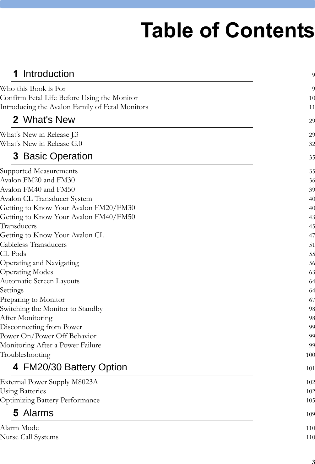


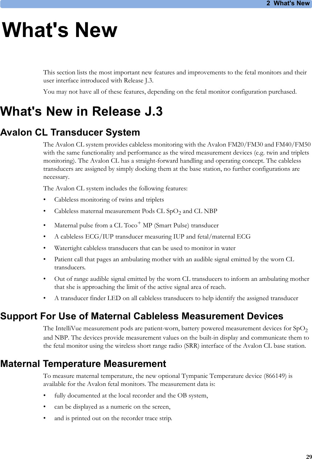


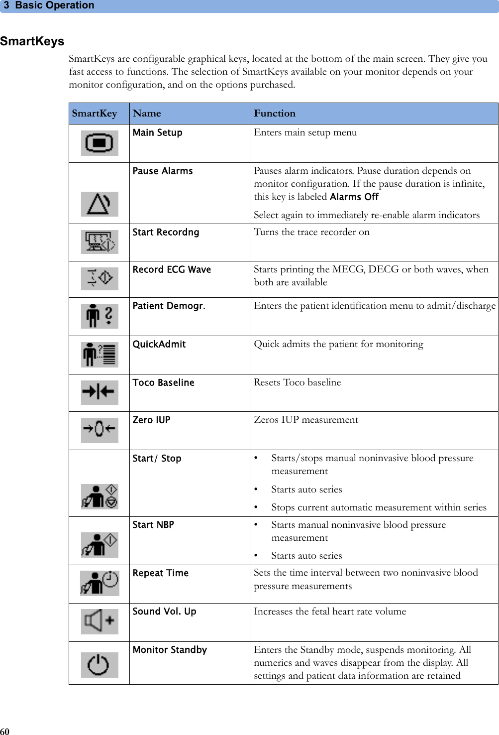
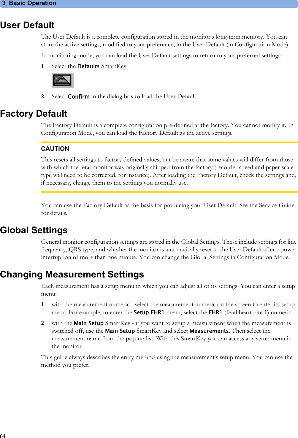

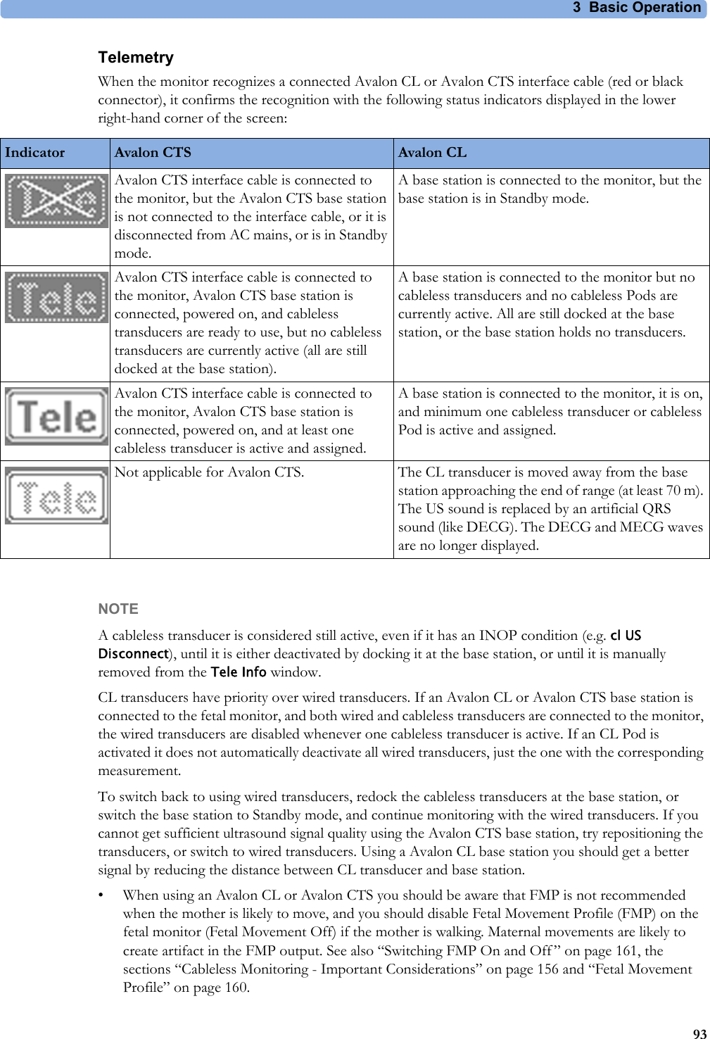


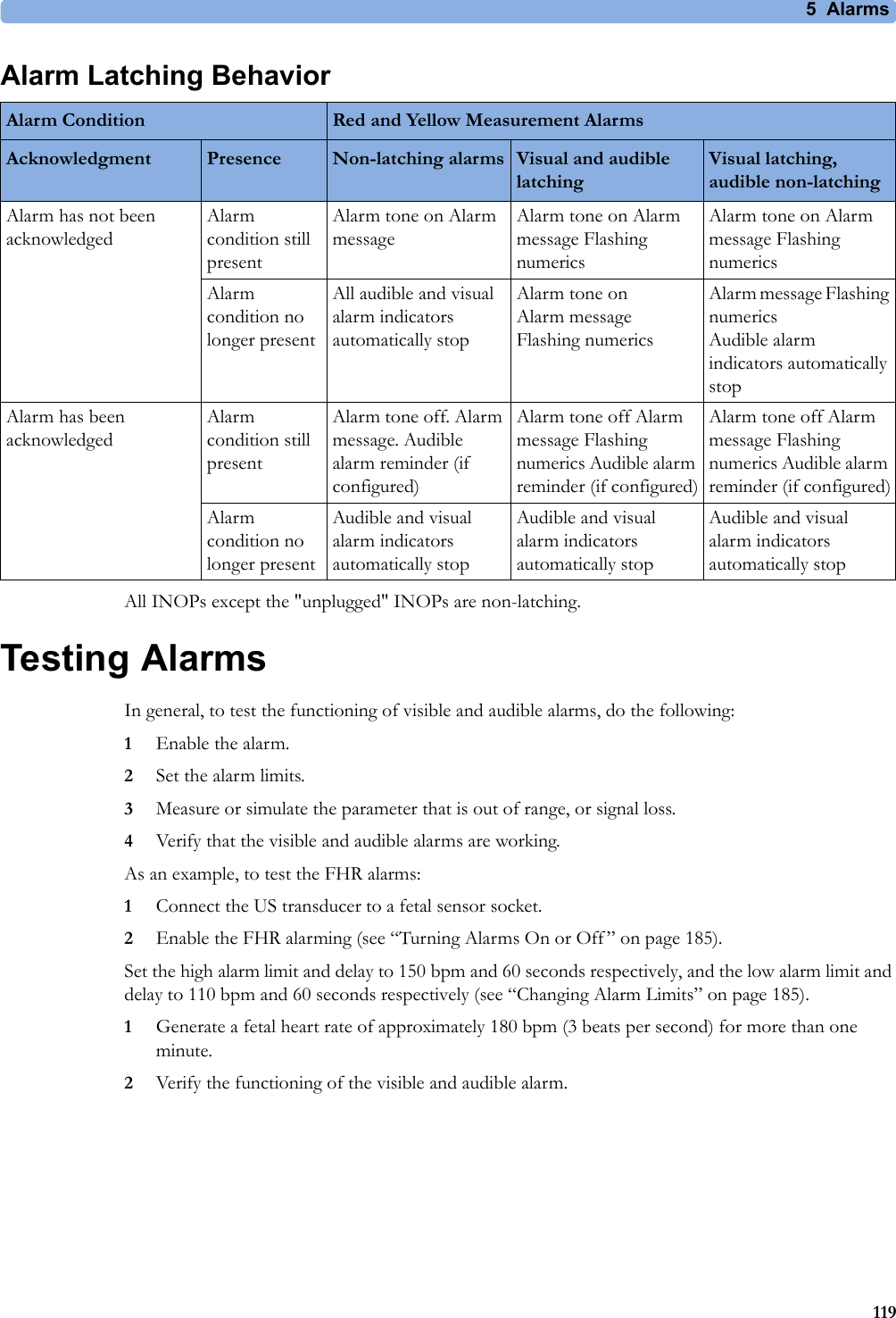

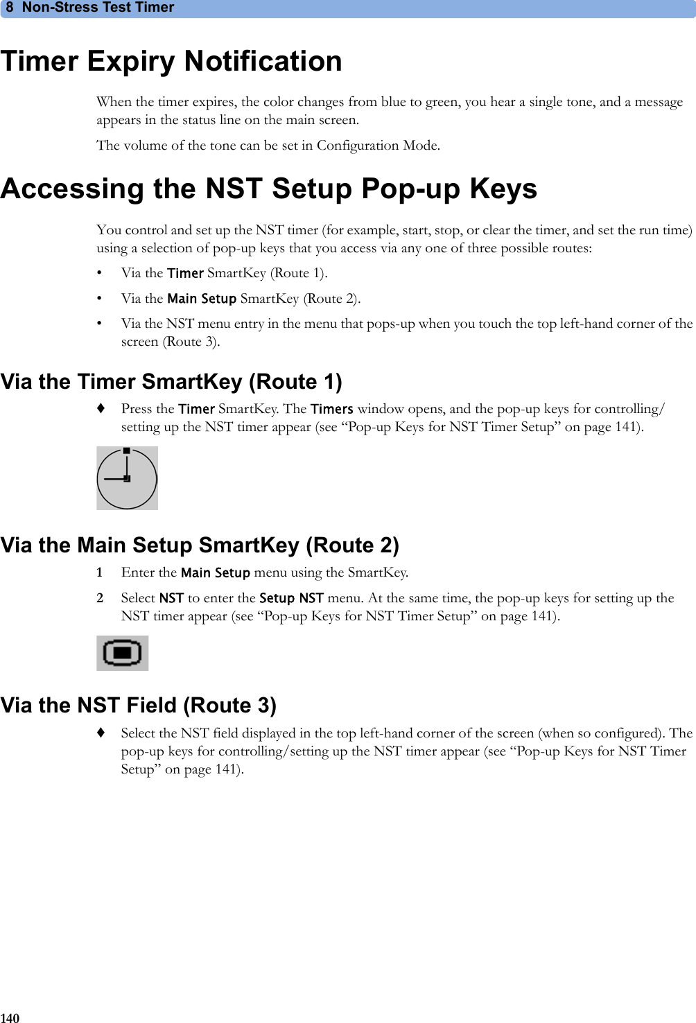
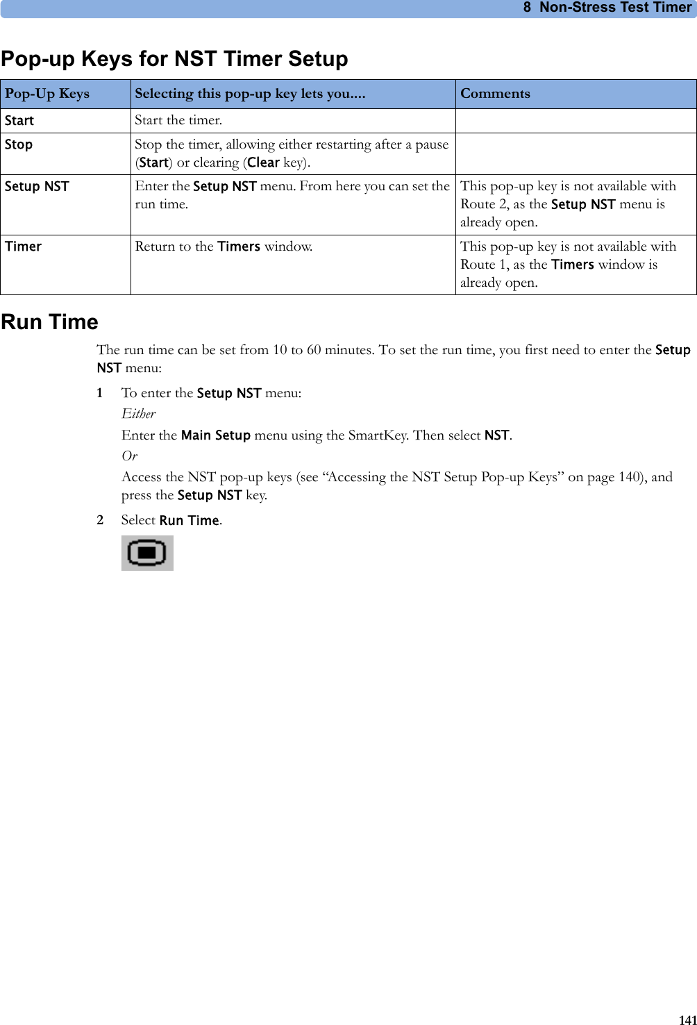

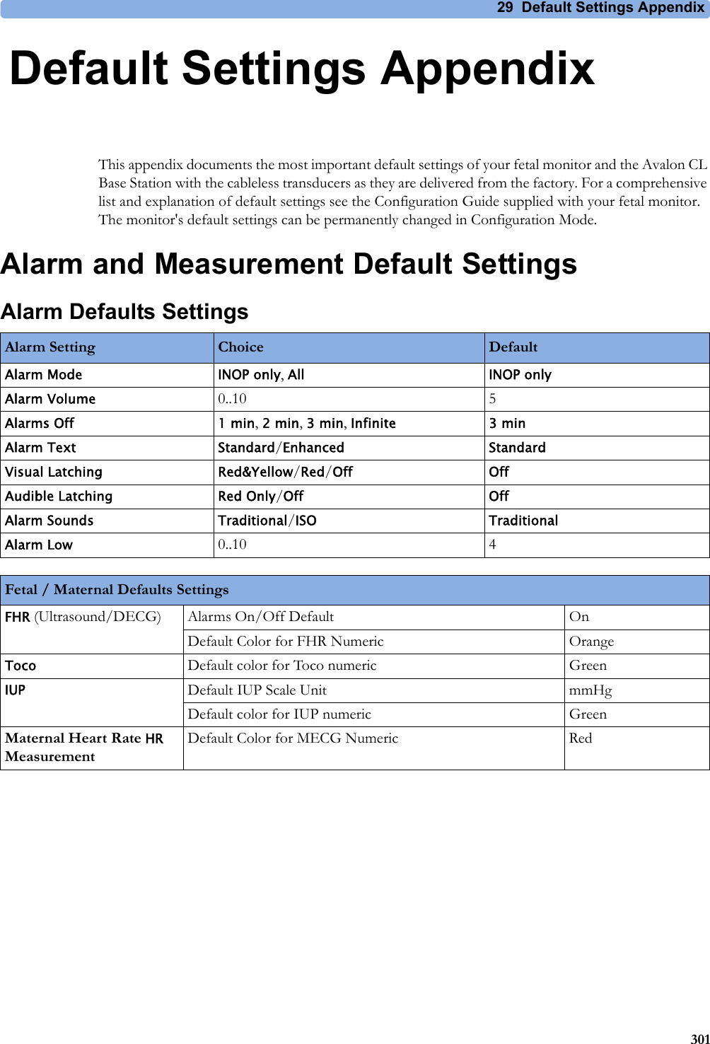
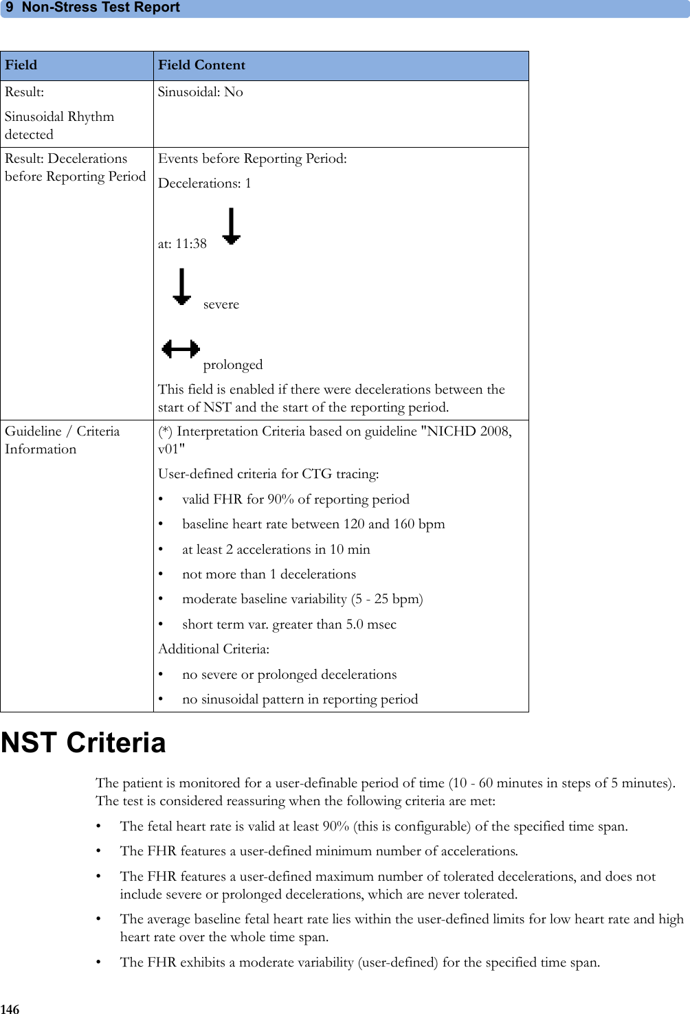
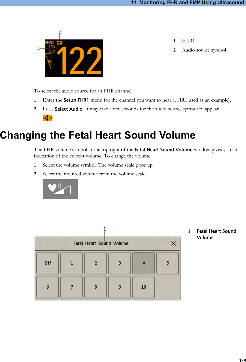
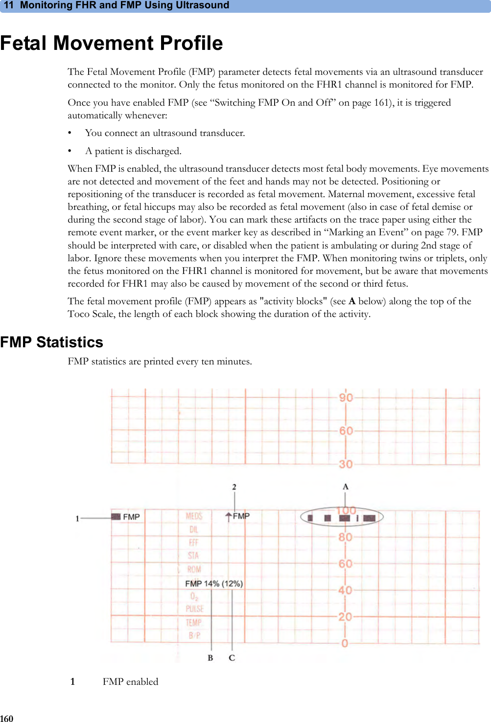
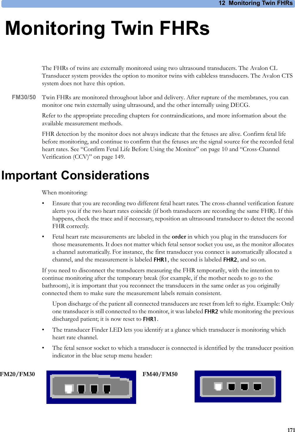
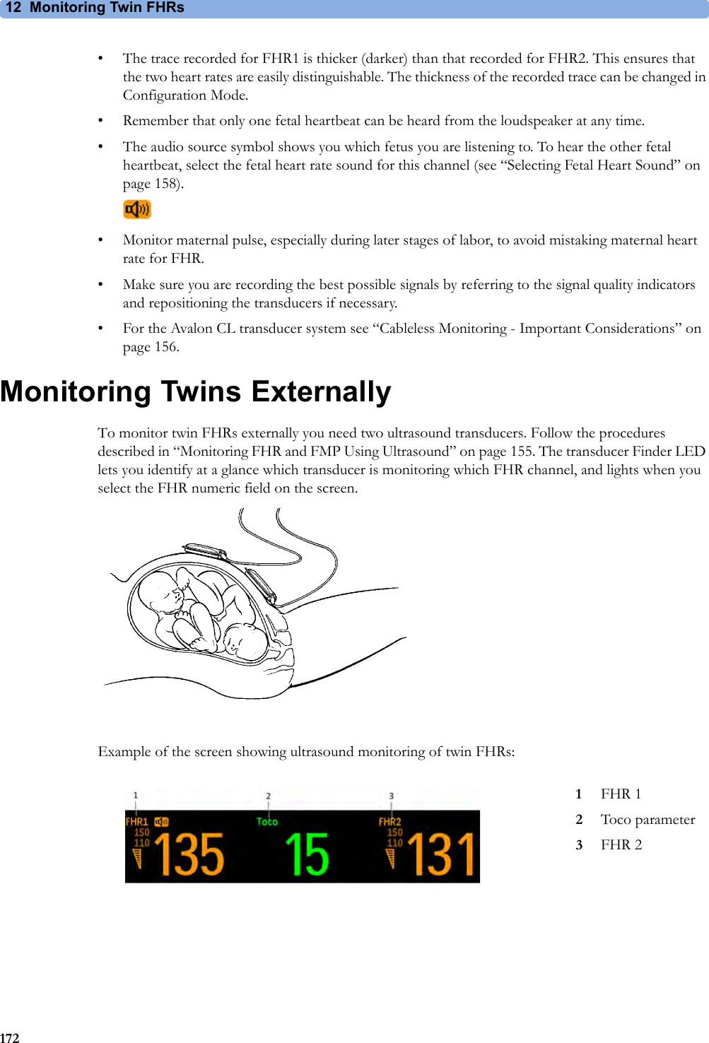
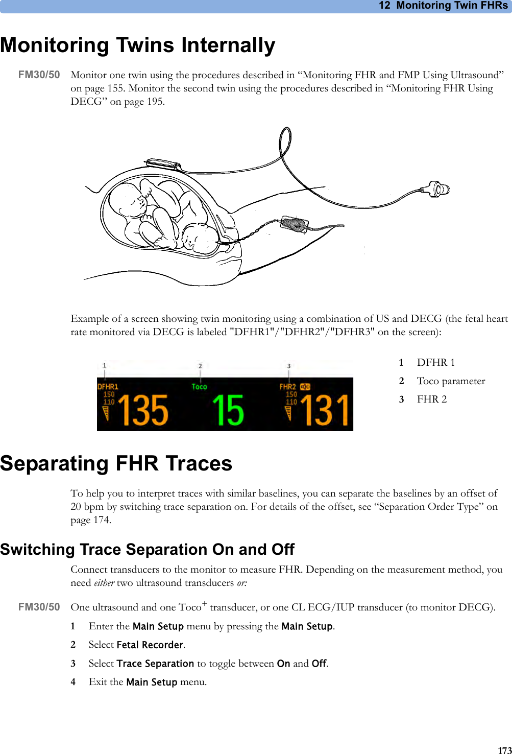
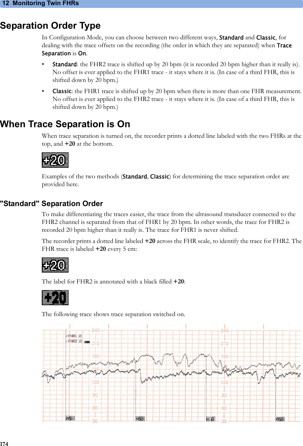
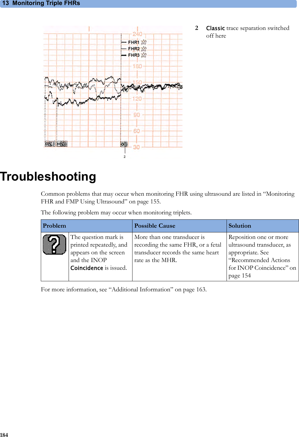
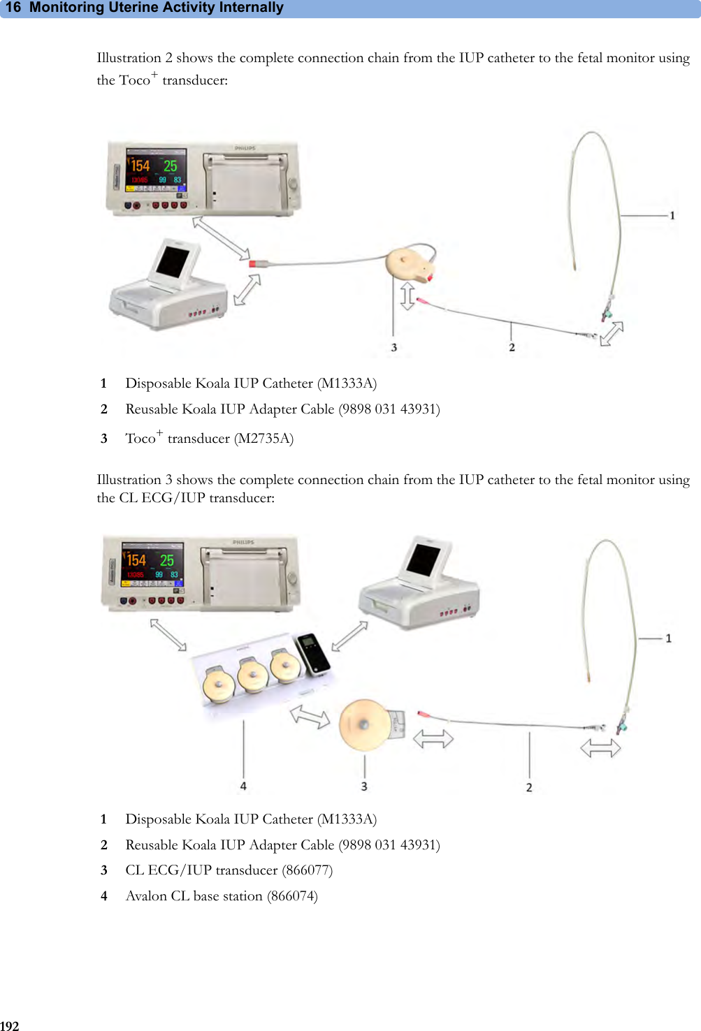
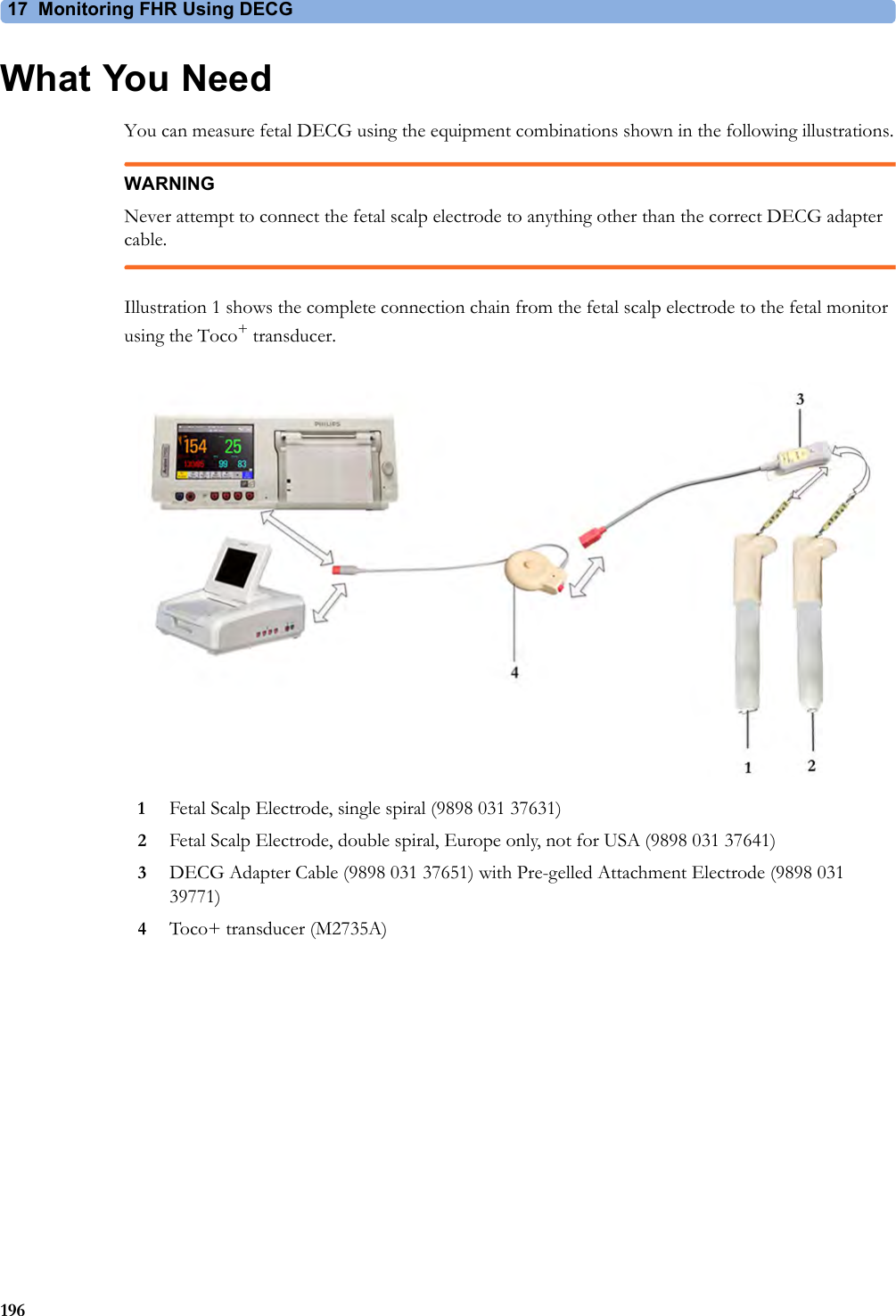
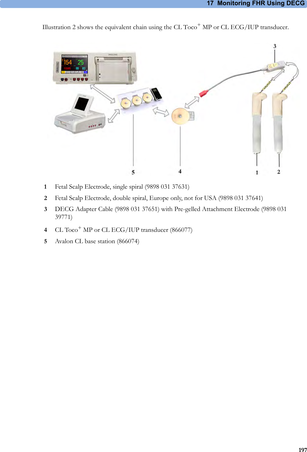
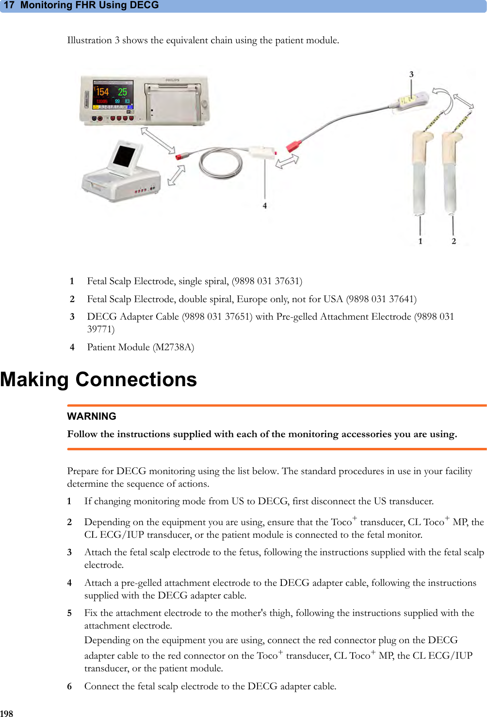
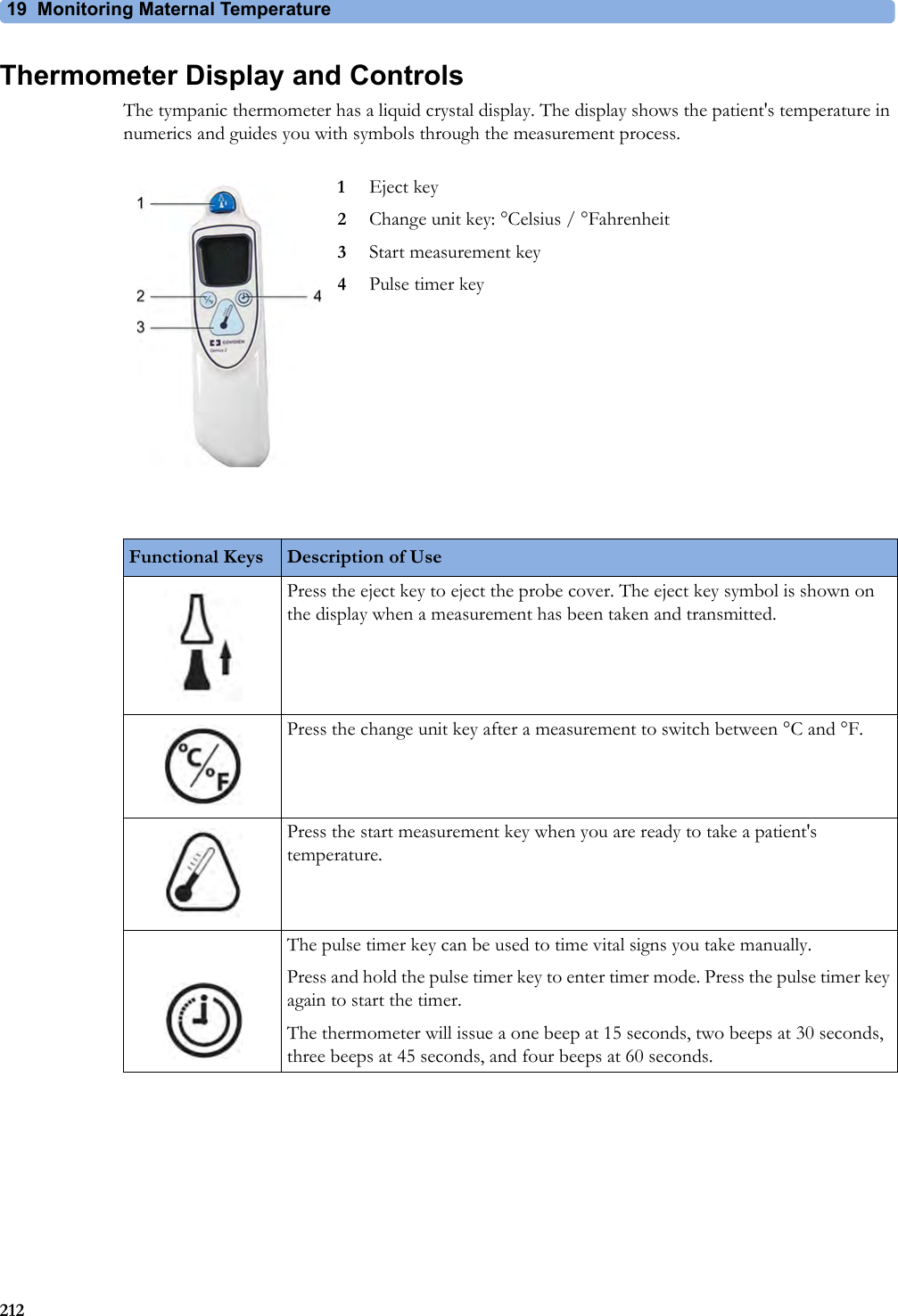
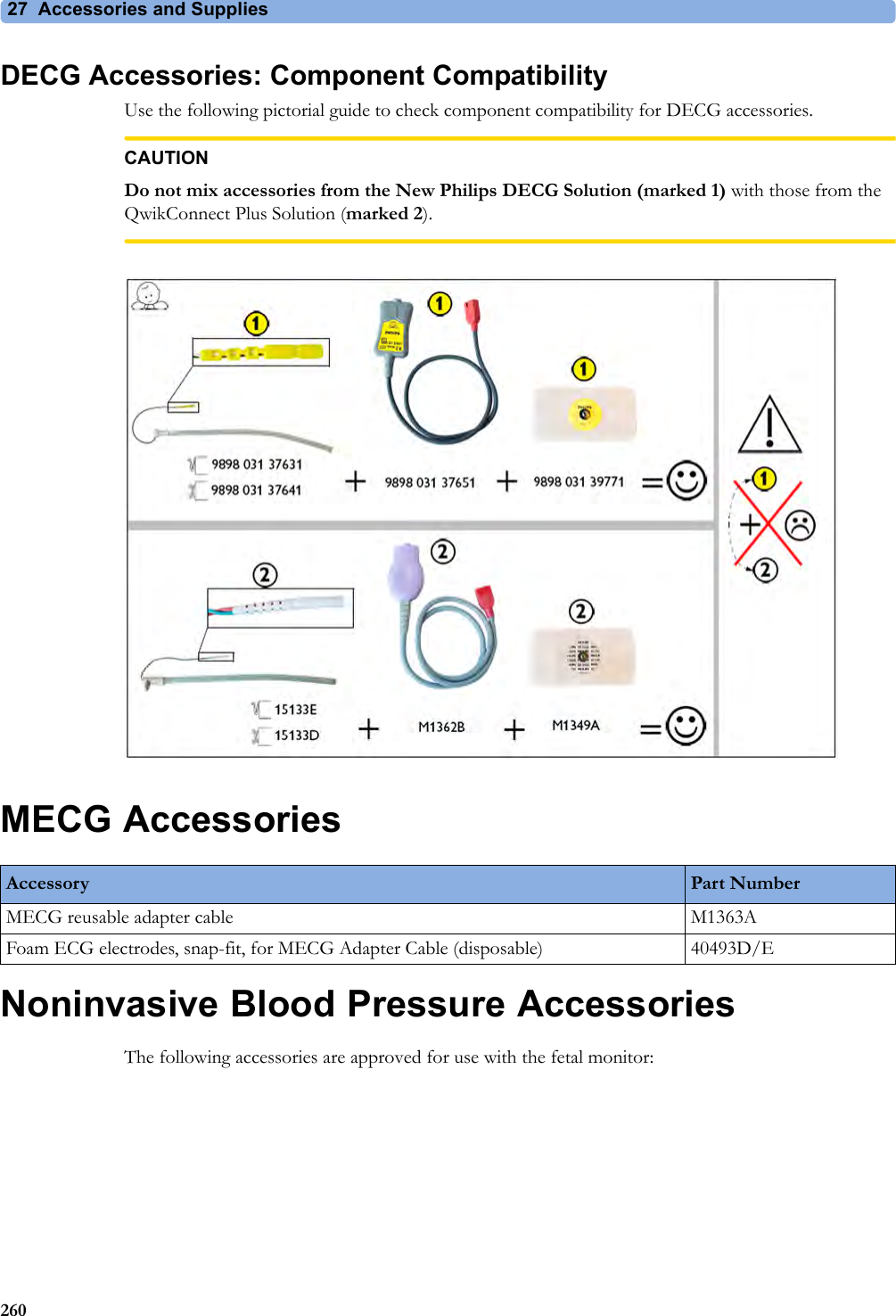
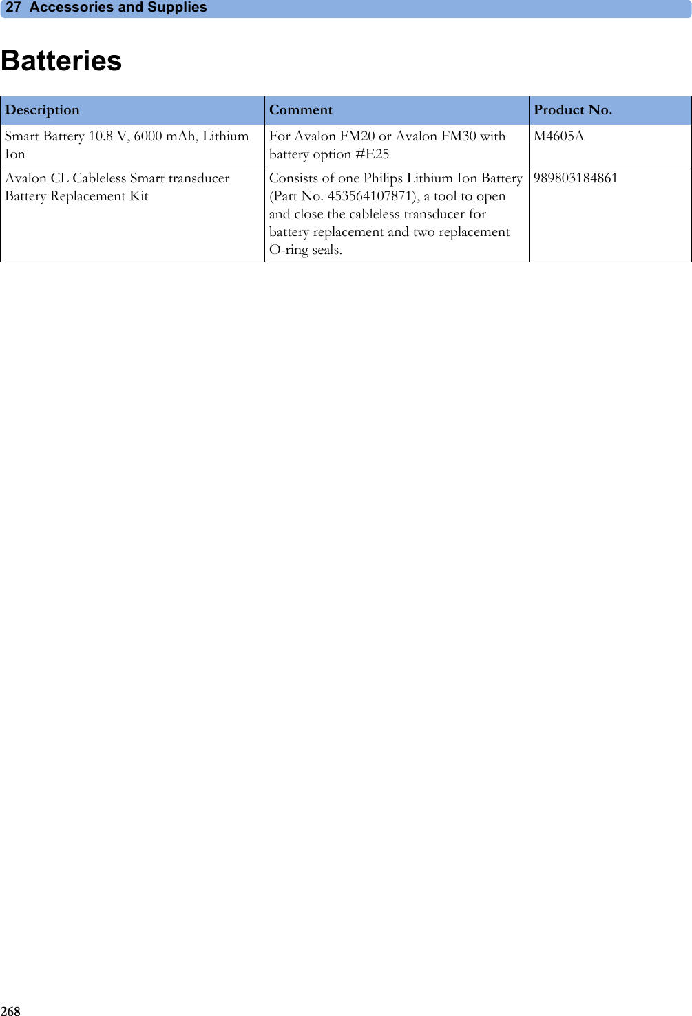
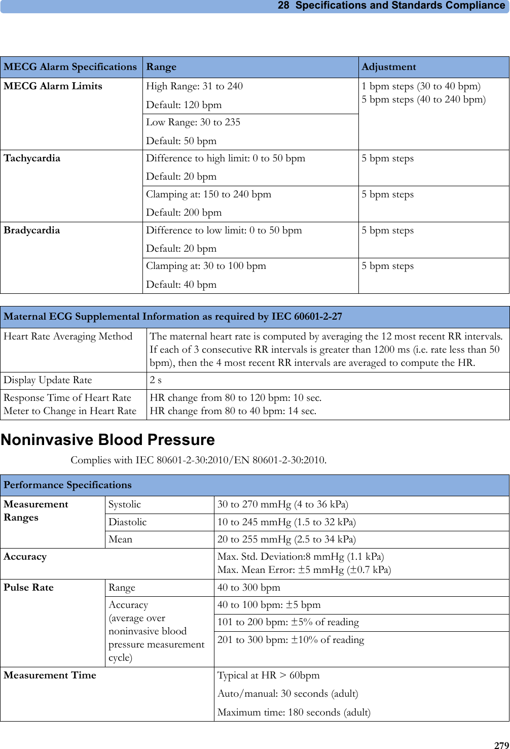
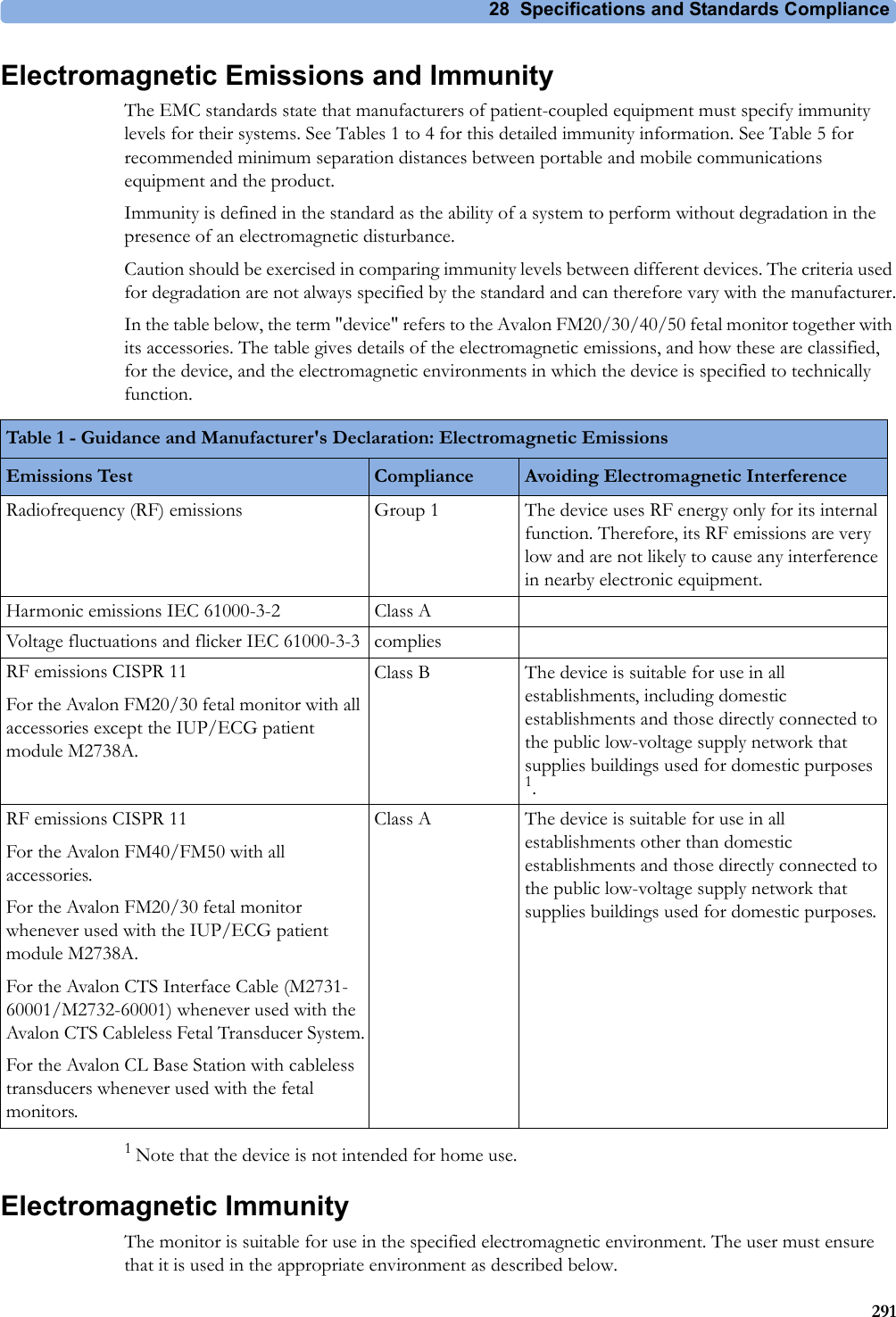
![9 Non-Stress Test Report1439Non-Stress Test ReportIt is generally accepted that a non stress test (NST) allows you to assess fetal well-being. The monitor's NST report process uses fetal ultrasound (but not DECG) heart rate traces and the Maternal Toco trace, generating a printed report when criteria are met and it is an indication of the fetal well-being. The American term Non Stress Test (NST) is used for antepartum testing. The interpretation algorithm and rule set are equivalent to those implemented in OB TraceVue Revision G.xx or IntelliSpace Perinatal H.xx and higher, and are based on the 2008 NICHD guidelines.An NST report is a diagnostic aid, but it does not replace the clinician’s judgment. The interpretation and the appropriate clinical response remain with the clinician.A fetus normally produces characteristic heart rate patterns. Average baseline variability and acceleration of the FHR in response to fetal movement are considered reassuring signs. This test does not take into account any form of external fetal stimulation.For every active ultrasound fetal heart rate measurement, one NST report can reside in the monitor’s memory. The reports are cleared when you discharge a patient and when you start a new NST report.When the NST Report option is available and the "NST Report" feature is "on", the NST status for all available ultrasound fetal heart rate measurements are displayed on the screen.The minimum displayed information is:• NST identification (by FHR number: 1, 2, 3)• Current NST status (by color: inverse for "not started yet", white for "running", yellow for "stopped", green for "finished")Setting Up an NST ReportTo setup NST Report functionality:1Enter the Main Setup menu and select the NST Report or2Select the NST Report SmartKey.3Press the "Setup" pop-up key.4Set your configuration options.Select from:•NST Analysis. Choose from On or Off.This switches the report feature on or off. This is linked to the NST timer. Both must be set to On for the NST report to function.•Report Recording. Choose from:–Manual - press the Record Report pop up key to trigger a manual request.–After Recorder Stop - report is recorded as soon as recorder becomes idle.–Immediately - If a realtime recording is running, the monitor pauses it. The recording is continued after the report has been recorded.Average short term variability (STV) value is documented in [bpm] and [ms] if STV is configured as part of the NST Report. This parameter is not considered as reassuring criteria.](https://usermanual.wiki/Philips-Medical-Systems-North-America/OBRTBV1.User-Manual/User-Guide-2013584-Page-143.png)


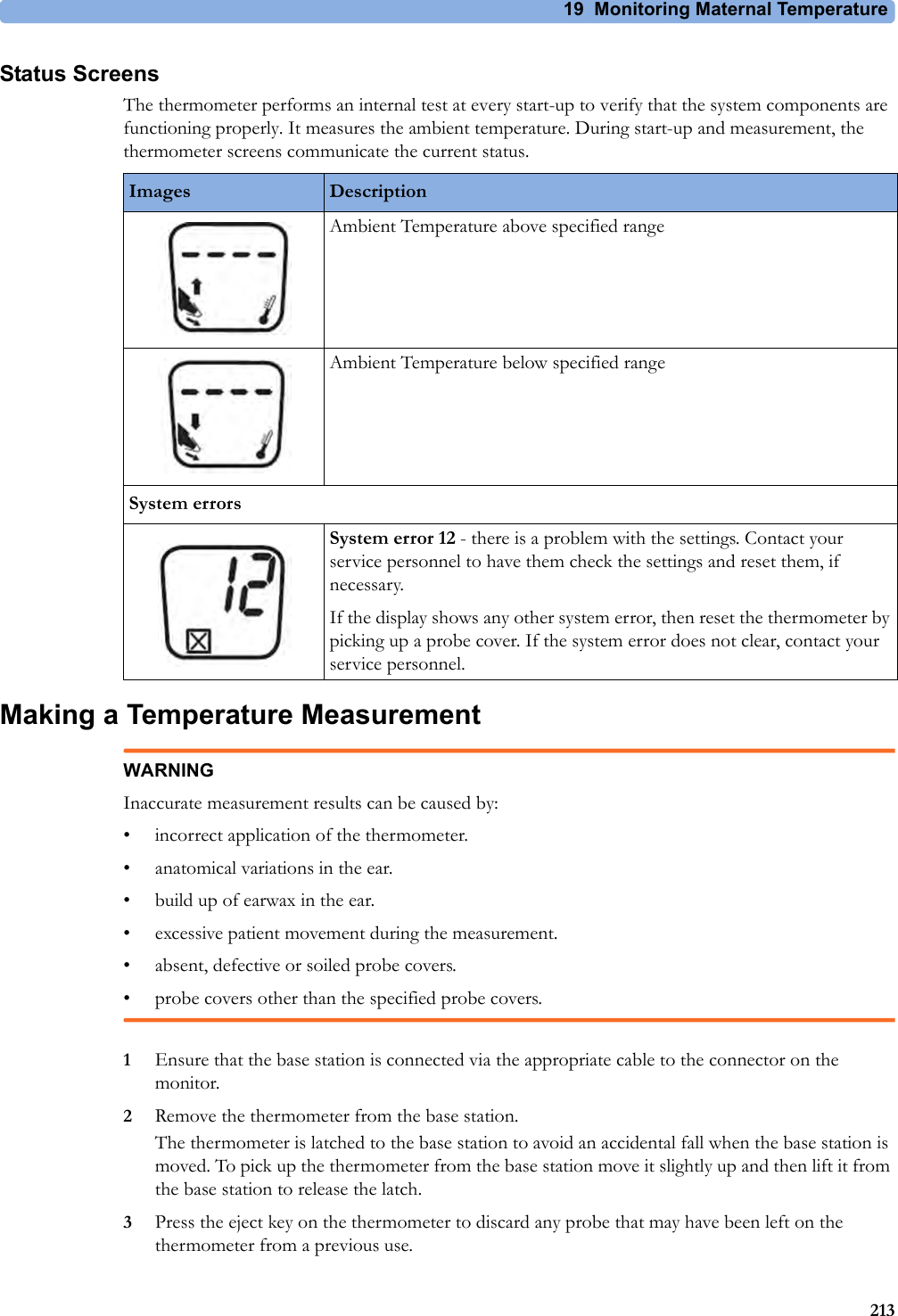


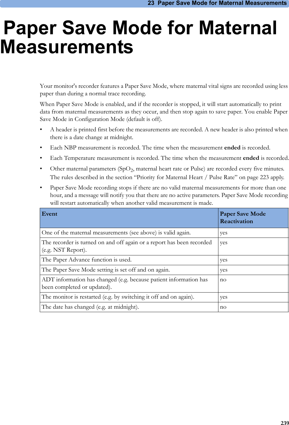


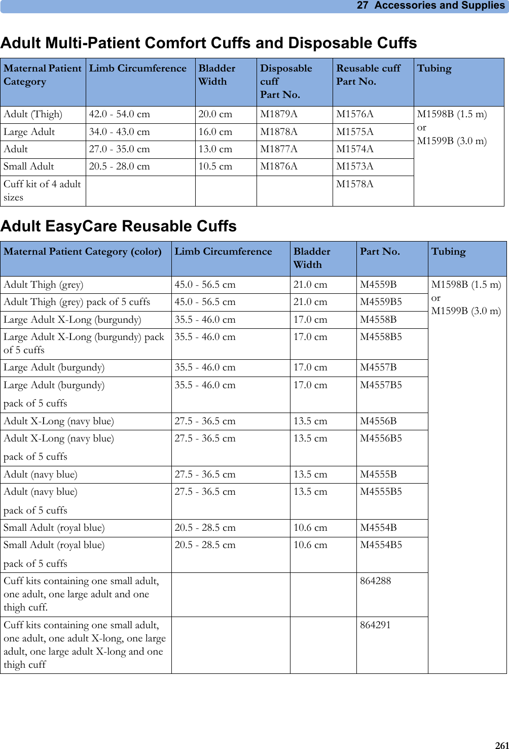
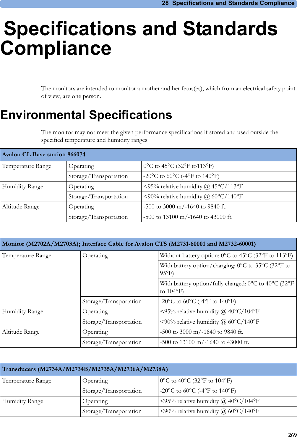
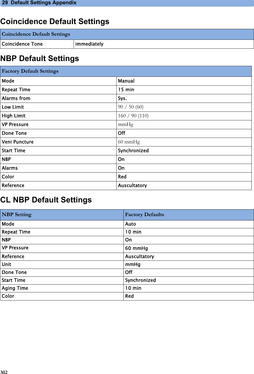
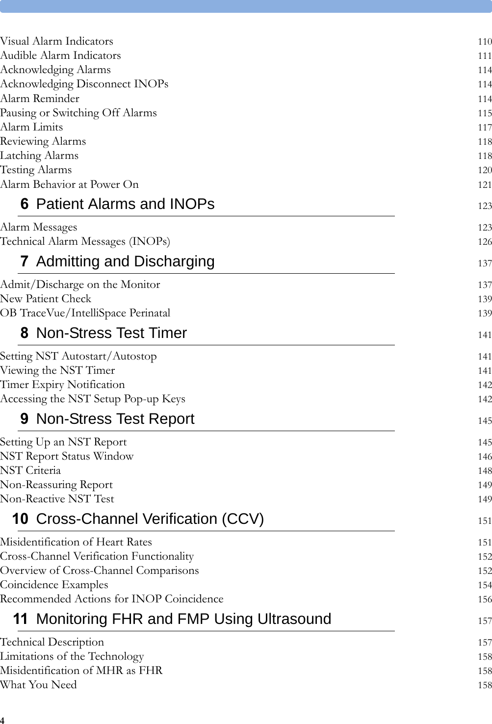
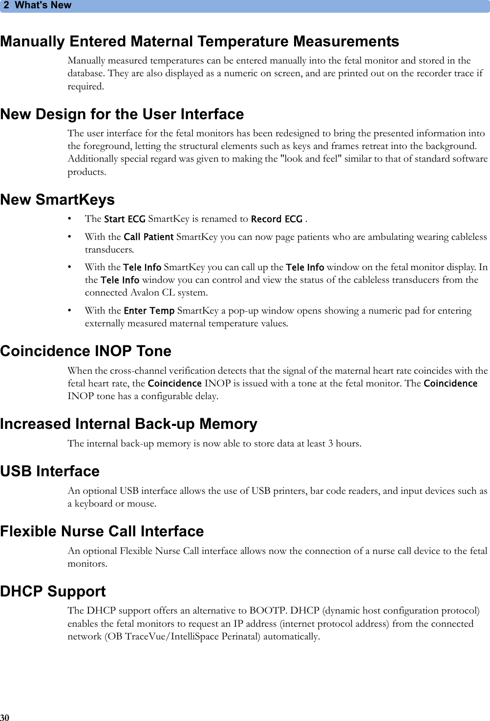
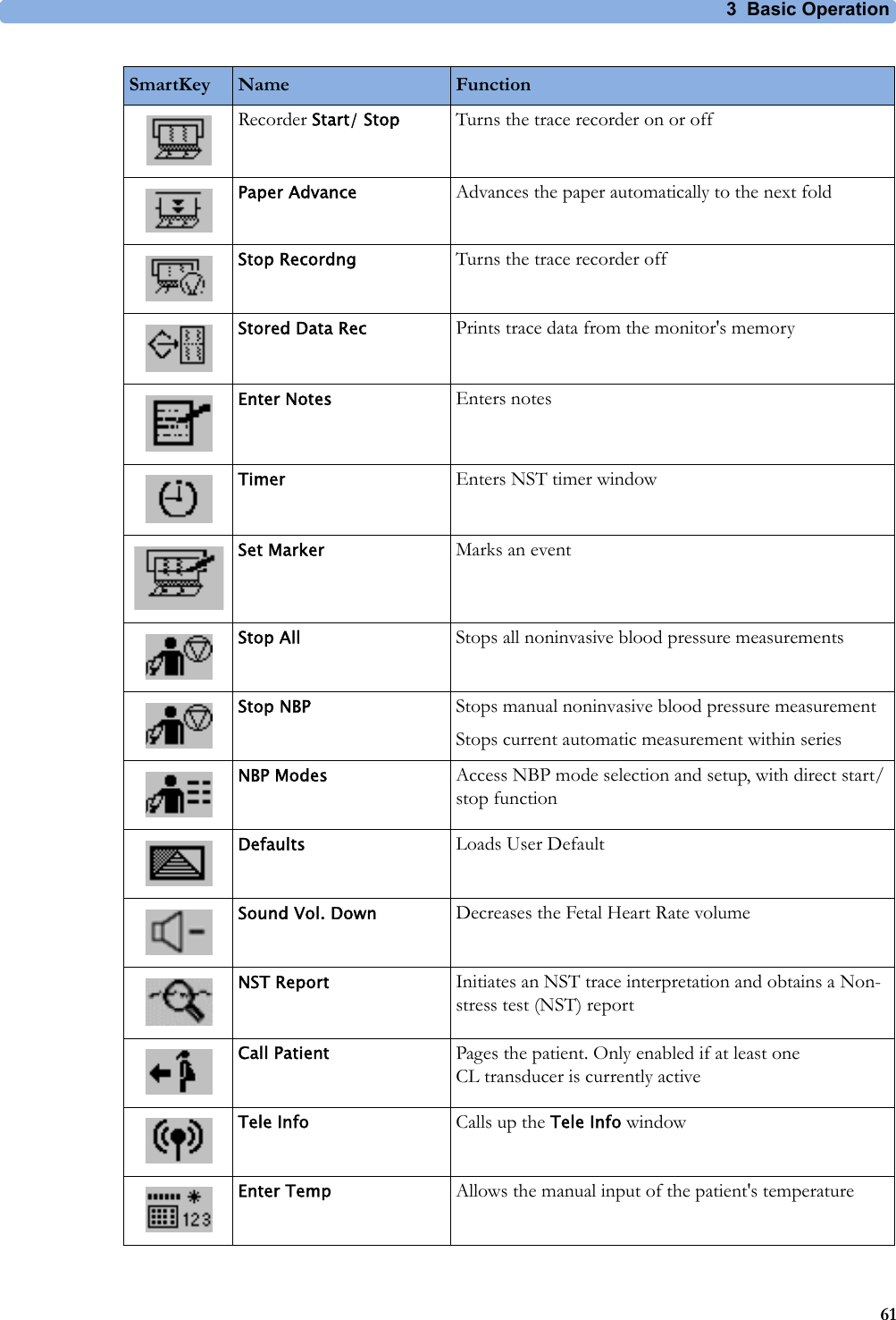
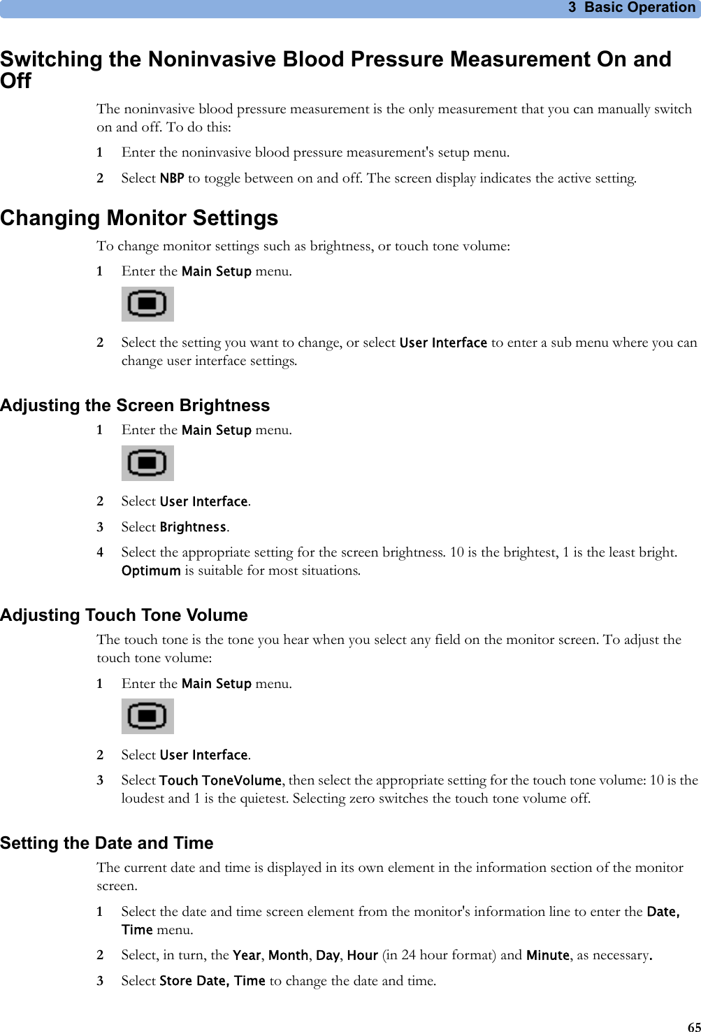
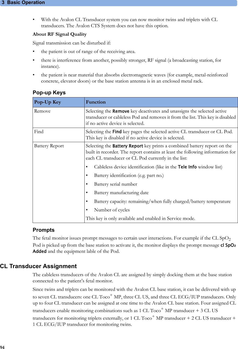
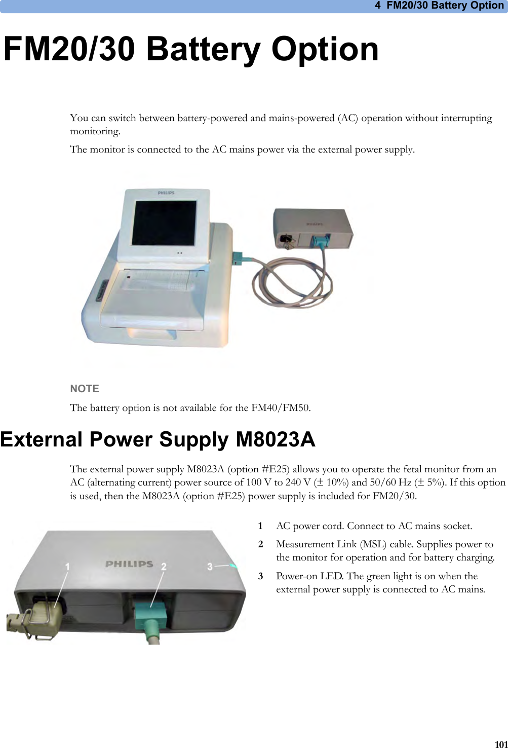
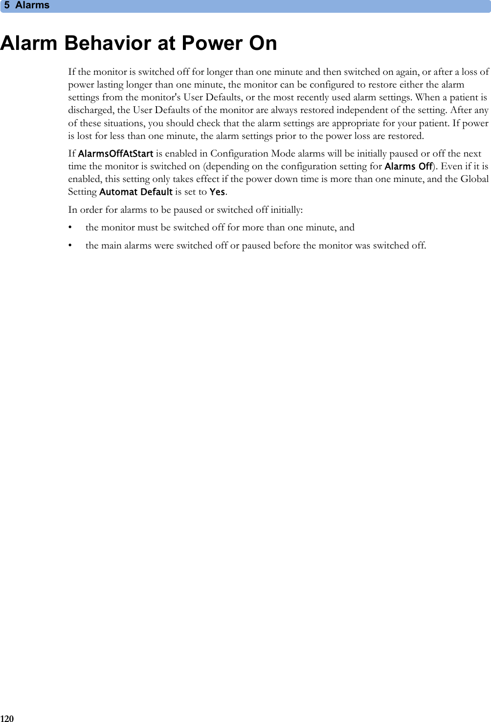
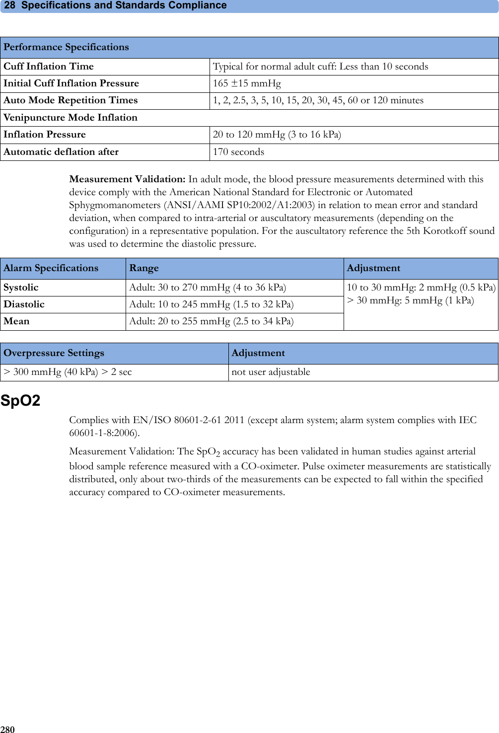
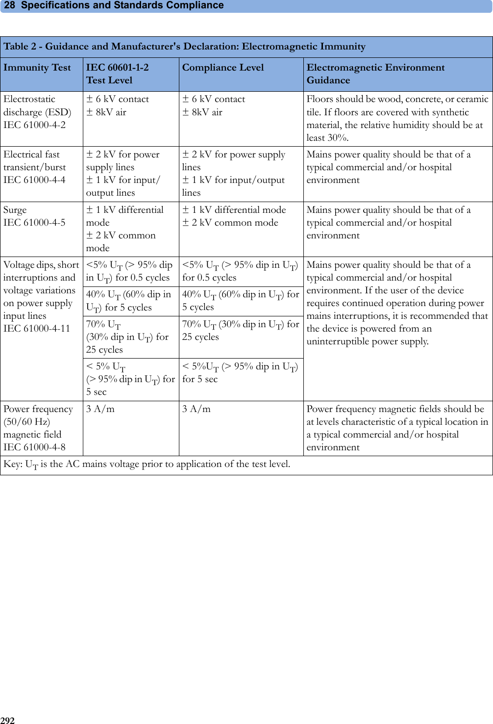
![28 Specifications and Standards Compliance273Interface Cable for Avalon CTS (M2731-60001 and M2732-60001)Shock Resistance Withstands a 1m drop to concrete surface with possible cosmetic damage onlyWater Ingress Protection Code IP X1Dimensions and Weight Maximum size mm/(in): width x height x depth55 x 28 x 50 (2.2 x 1.1 x 2.0 in)Cable length 2.5 mWeight < 200 g/7.0 oz.M8023A (Option #E25) External Power Supply Weight and DimensionsMaximum Weight 700 g ±10% (1.5 lb ±10%)Size (W x H x D) 207 x 70 x 113 mm / 8.1 x 2.8 x 4.4 inInterface SpecificationsNetwork Standard 100-Base-TX (IEEE 802.3 Clause 25)Connector RJ45 (8 pin)Isolation Basic insulation (reference voltage: 250 V; test voltage: 1500 V)MIB/RS232 Standard IEEE 1073-3.2-2000Connectors RJ45 (8 pin)Mode Software-controllableBCC (RxD/TxD cross over) orDCC (RxD/TxD straight throughPower 5 V ±5 %, 100 mA (max.)Isolation Basic insulation (reference voltage: 250 V; test voltage: 1500 V)USB Interface Standard USB 2.0 full-speed (embedded host)Connectors USB series "Standard A" receptaclePower Low power port 4.4V min; max. load for all ports together 500 mAIsolation noneRS232 (Standard) Connectors RJ45 (8-pin)Power noneInsulation Basic insulation (reference voltage: 250 V; test voltage: 1500 V)RS232 (Independent display interface option)Connectors RJ45 (8-pin)Power noneIsolation noneBasic Nurse Call Relay Connectors Modular Jack 6P6C, active open and closed contactContact <=100 mA, <=24 V DCIsolation Basic insulation (reference voltage: 250 V; test voltage: 1500 V)Delay <[Configured Latency +0.5] sec](https://usermanual.wiki/Philips-Medical-Systems-North-America/OBRTBV1.User-Manual/User-Guide-2013584-Page-273.png)
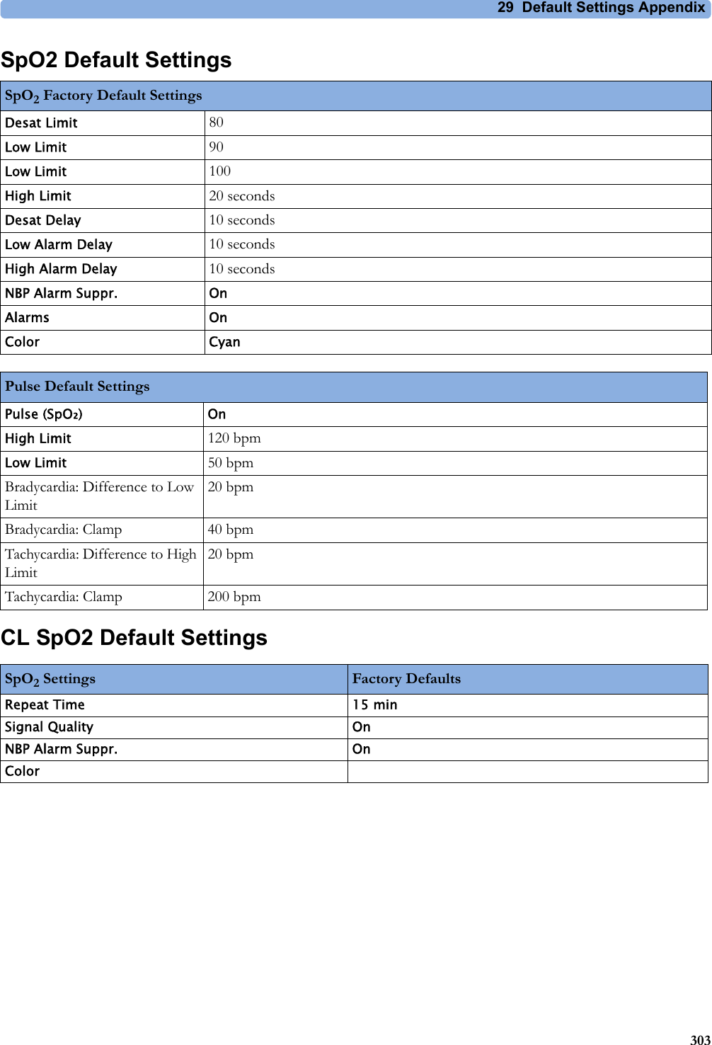
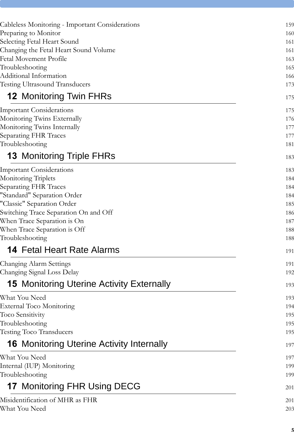
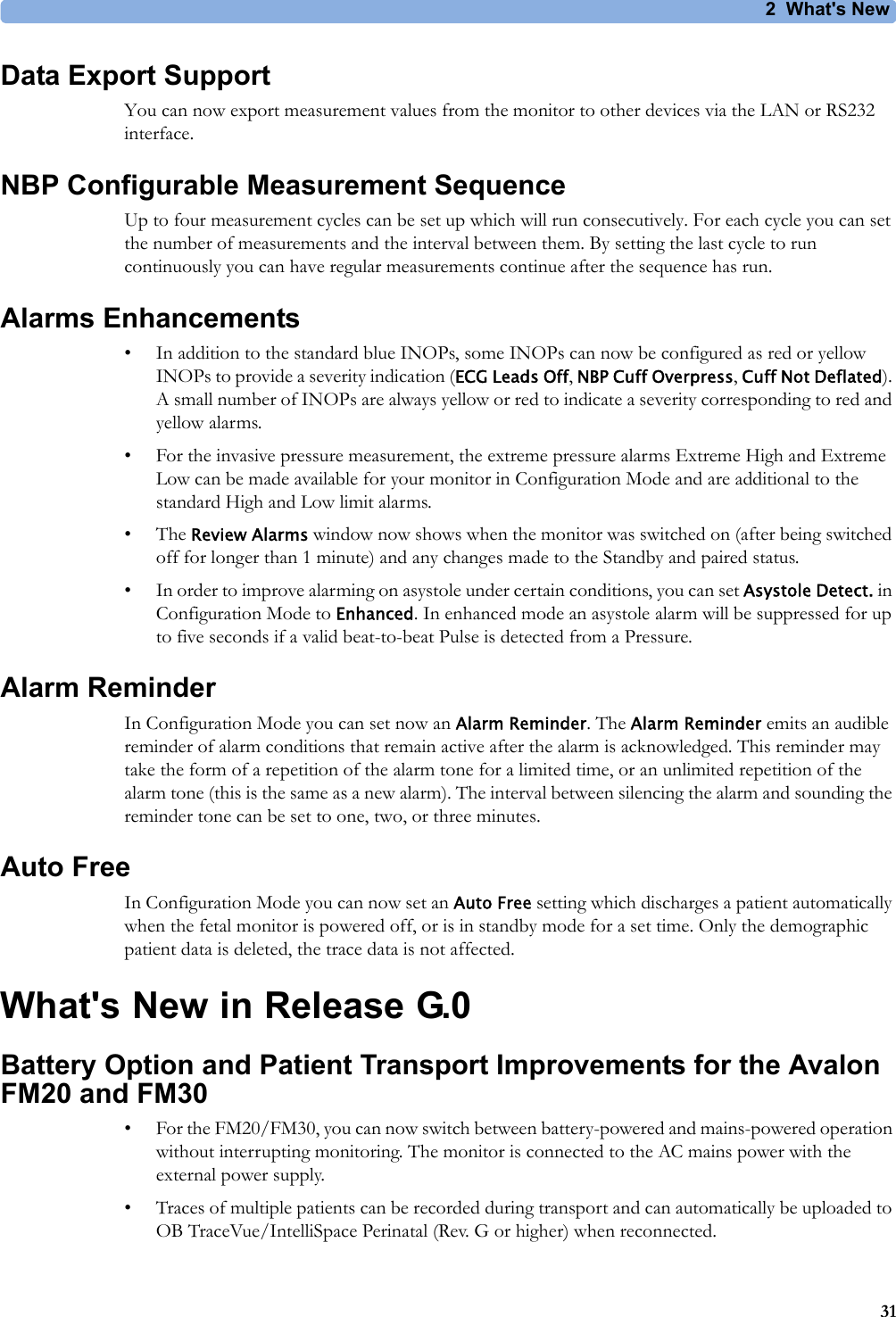
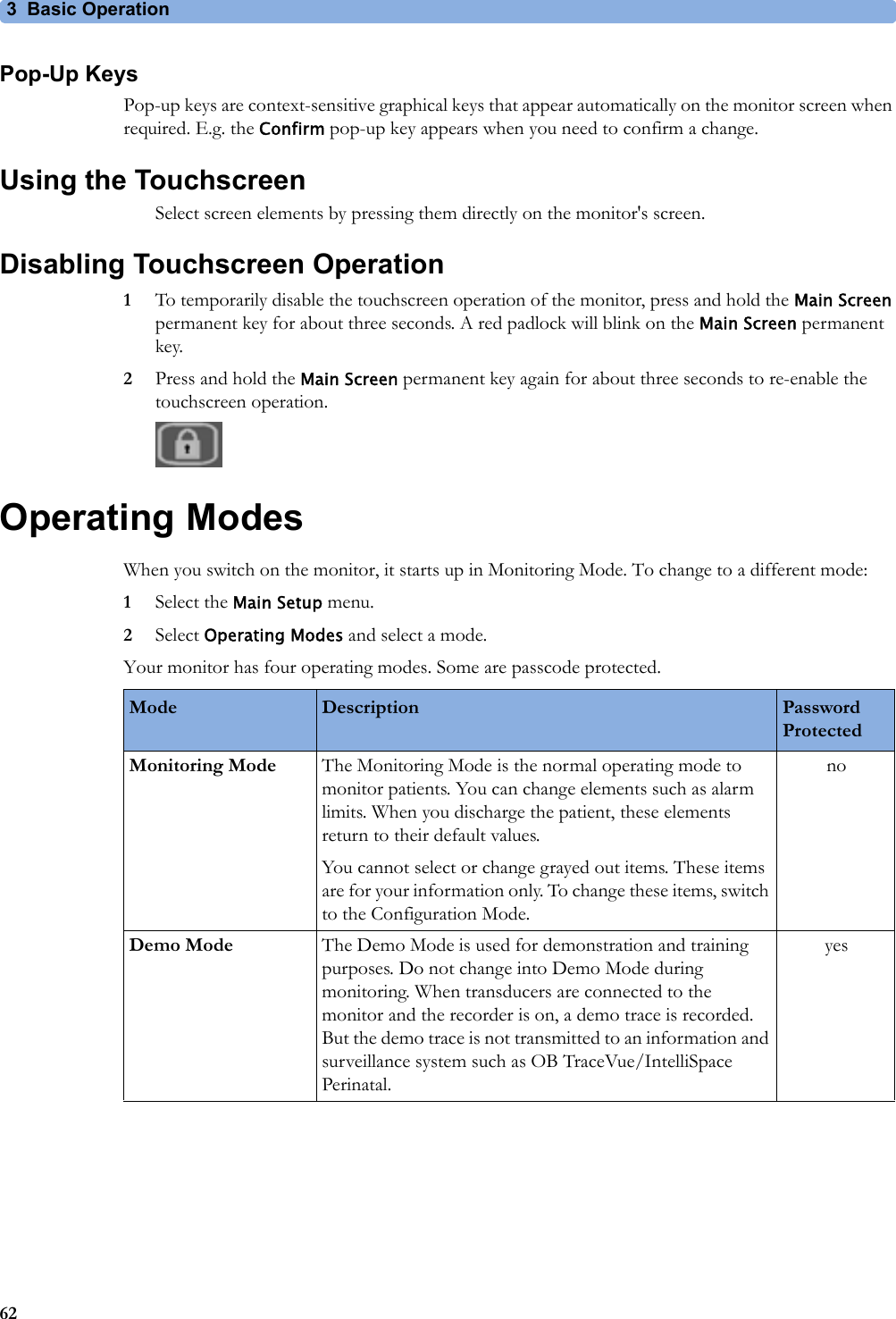
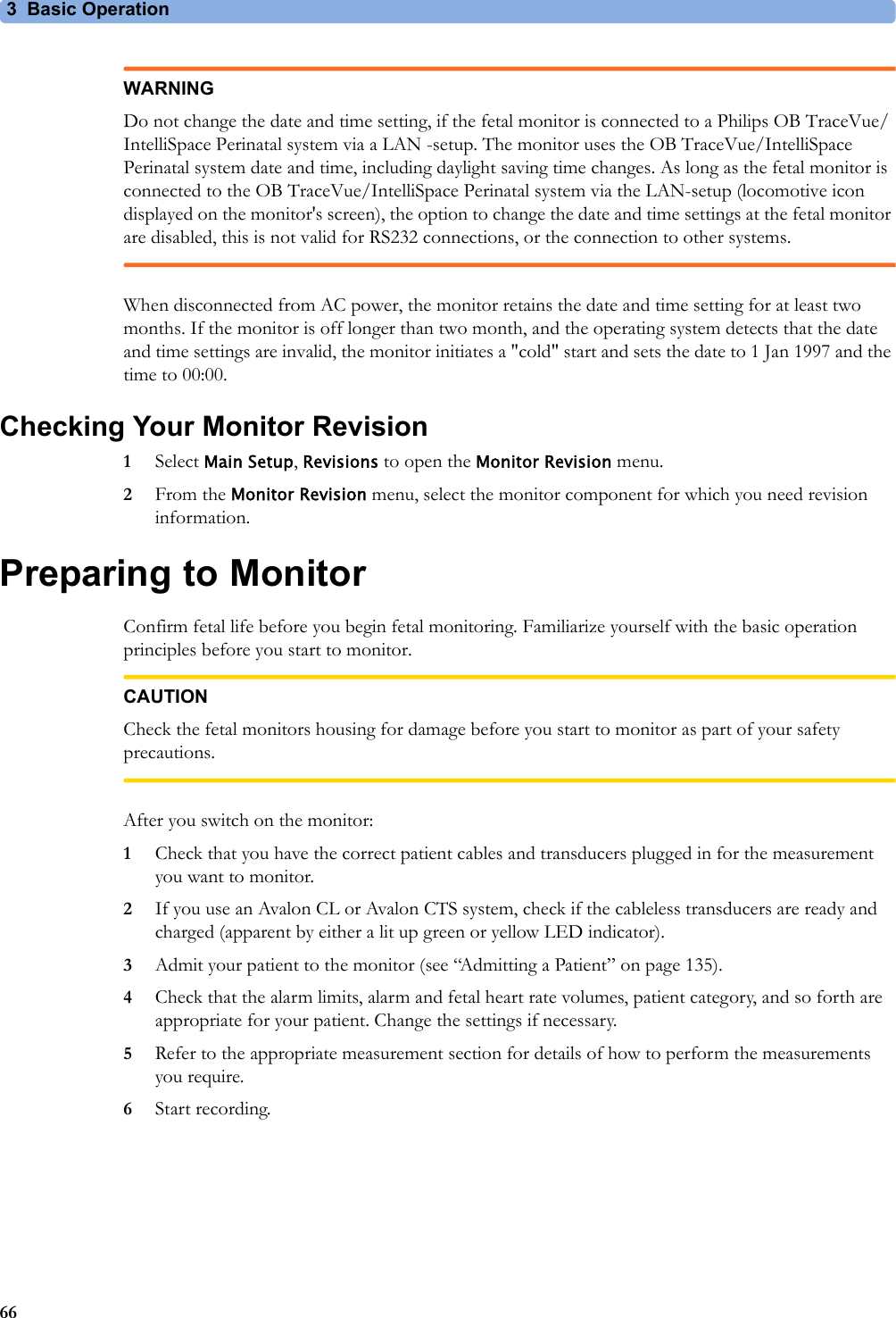
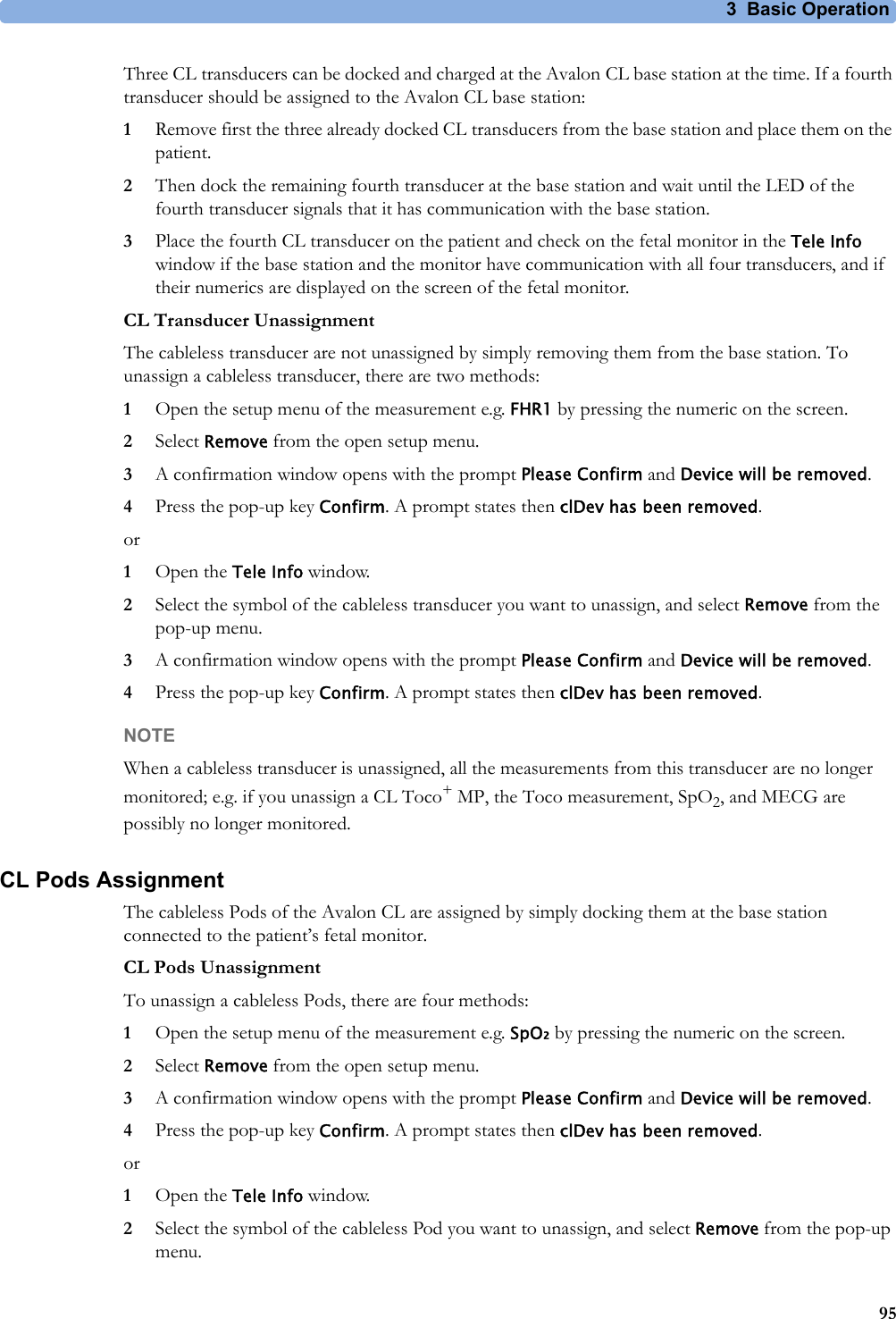
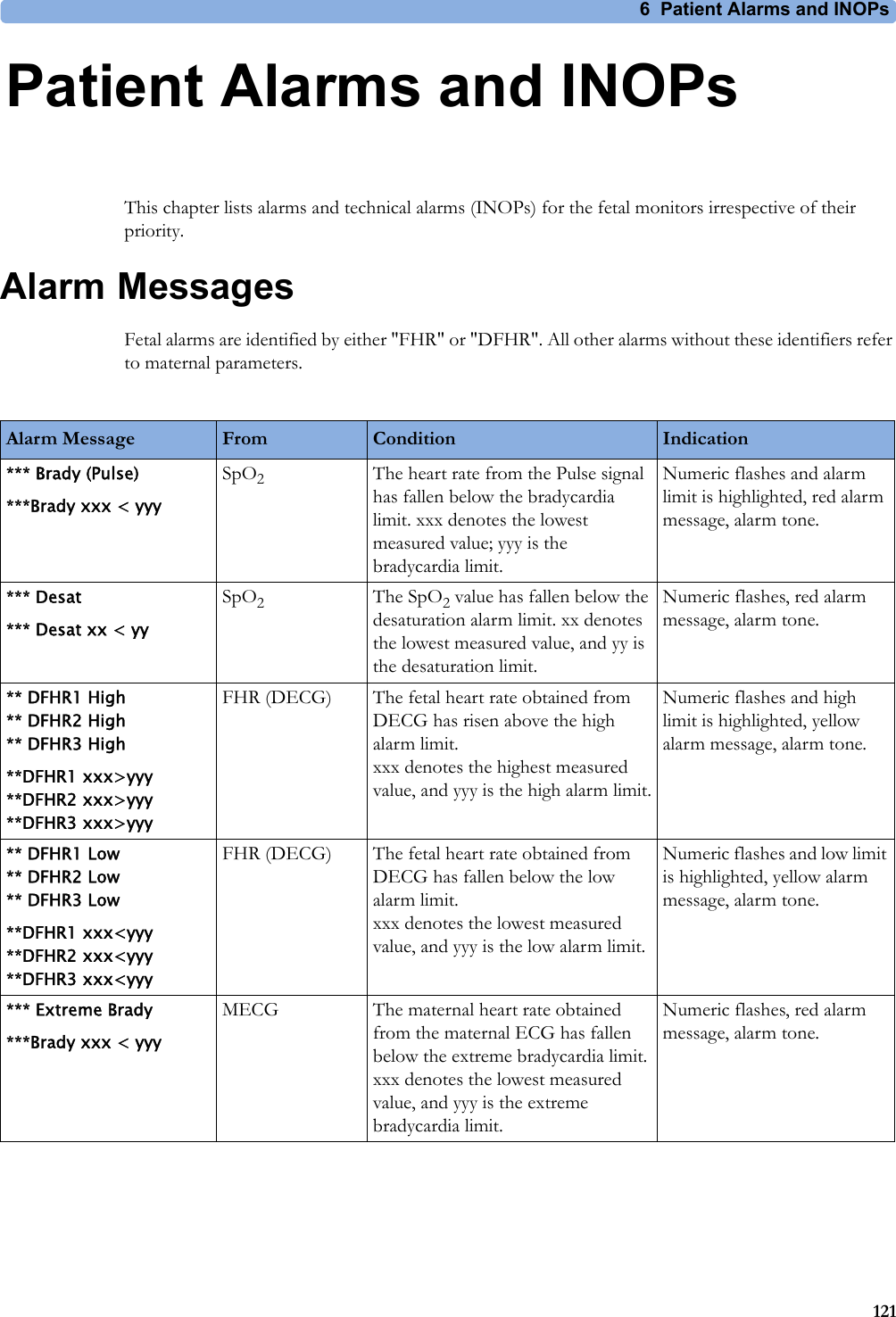
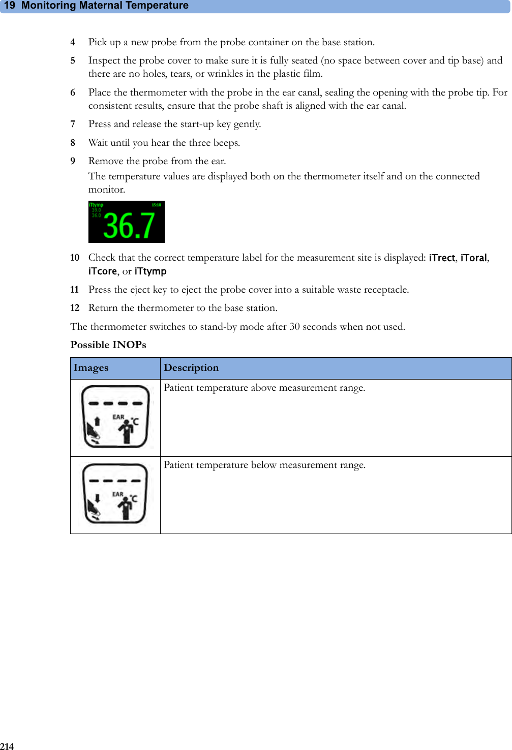
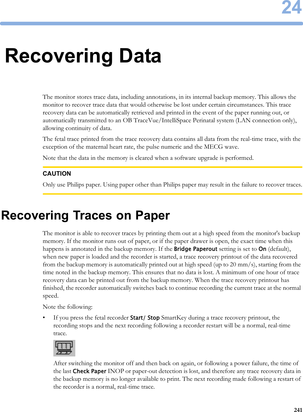
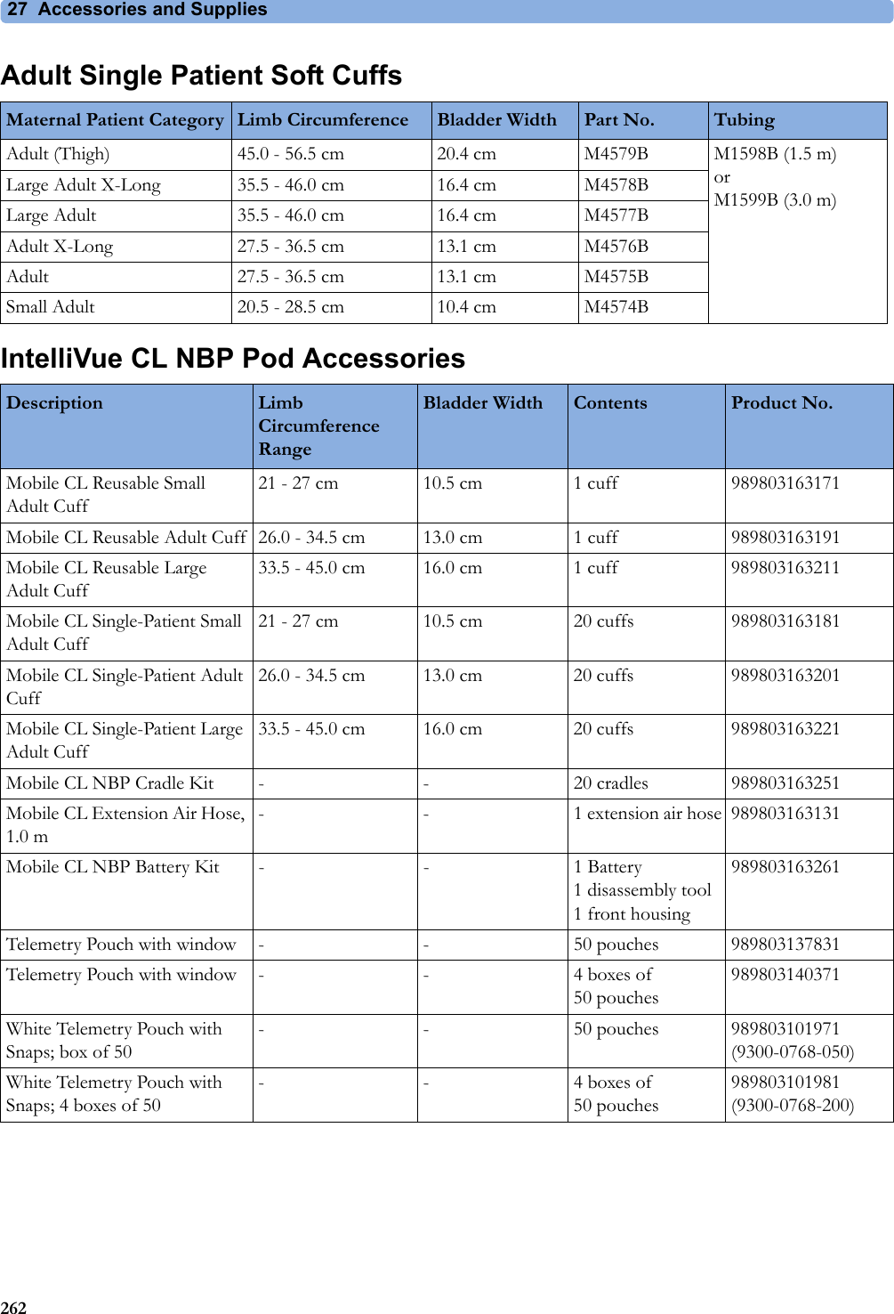
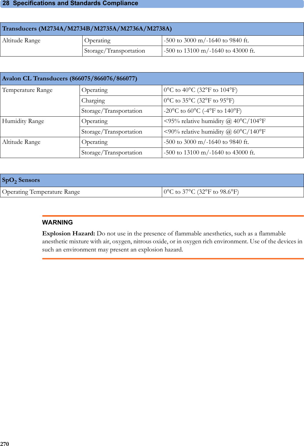
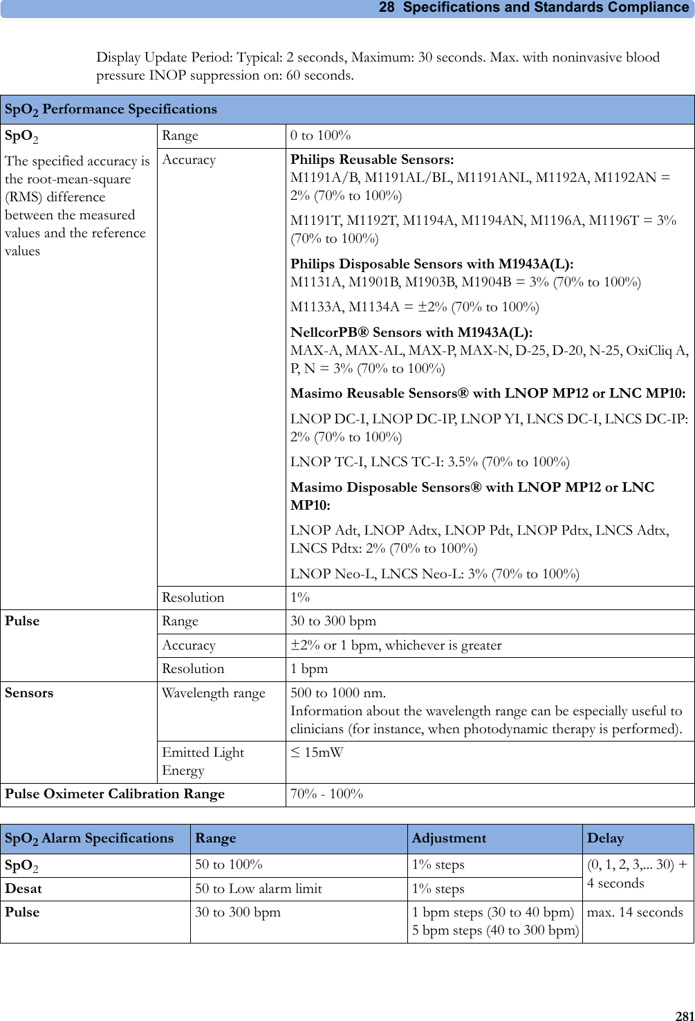
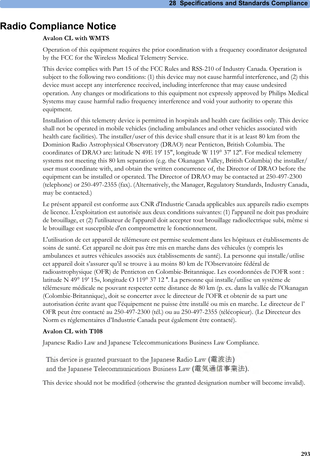
![28 Specifications and Standards Compliance2741 The power loss indication functionality of the Nurse Call Relay board is not supported with fetal monitors.Flexible Nurse Call Relay1Connectors 20 pin MDR (Mini D-Ribbon), active open and closed contactsContact <=100 mA, <=24 V DCIsolation Basic insulation (reference voltage: 250 V; test voltage: 1500 V)Delay <[Configured Latency +0.5] secInterface SpecificationsAvalon CL Radio Interface SpecificationsShort Range Radio Interface Type Internal SRR interfaceTechnology IEEE 802.15.4Frequency Band 2.4 GHz ISM (2.400 - 2.483 GHz)Modulation Technique DSSS (O -QPSK)Effective radiated power max. 0 dBm (1 mW)Range ca. 5 m without any physical obstructions as walls and doorsOBR (WMTS) Frequency Band 608 - 614 MHzEffective radiated power <20 mW (Base Station) <1 mW (CL transducers)Range min. 70 mOBR (ISM) Frequency Band 433.05 -434.79 MHzEffective radiated power <10 mW (Base Station)<1 mW (CL transducers)Range min. 70 mOBR (T108) Frequency Band 920.6 - 923.4 MHZEffective radiated power <20 mW (Base Station) <10 mW (CL transducers)Range min. 70 m](https://usermanual.wiki/Philips-Medical-Systems-North-America/OBRTBV1.User-Manual/User-Guide-2013584-Page-274.png)

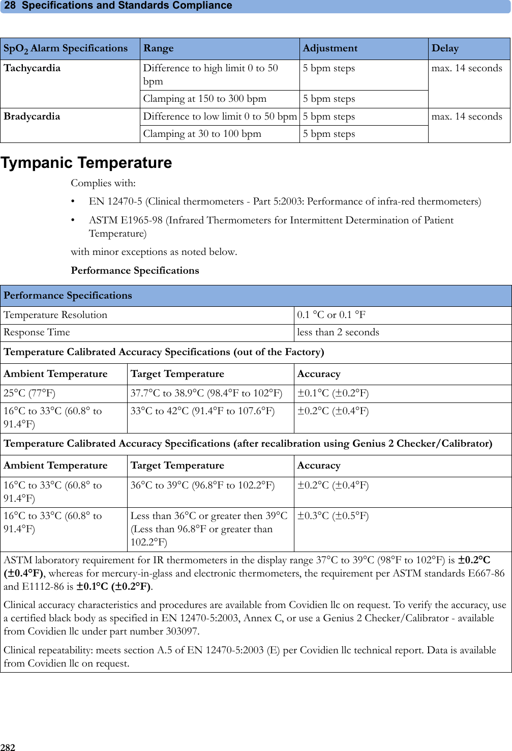
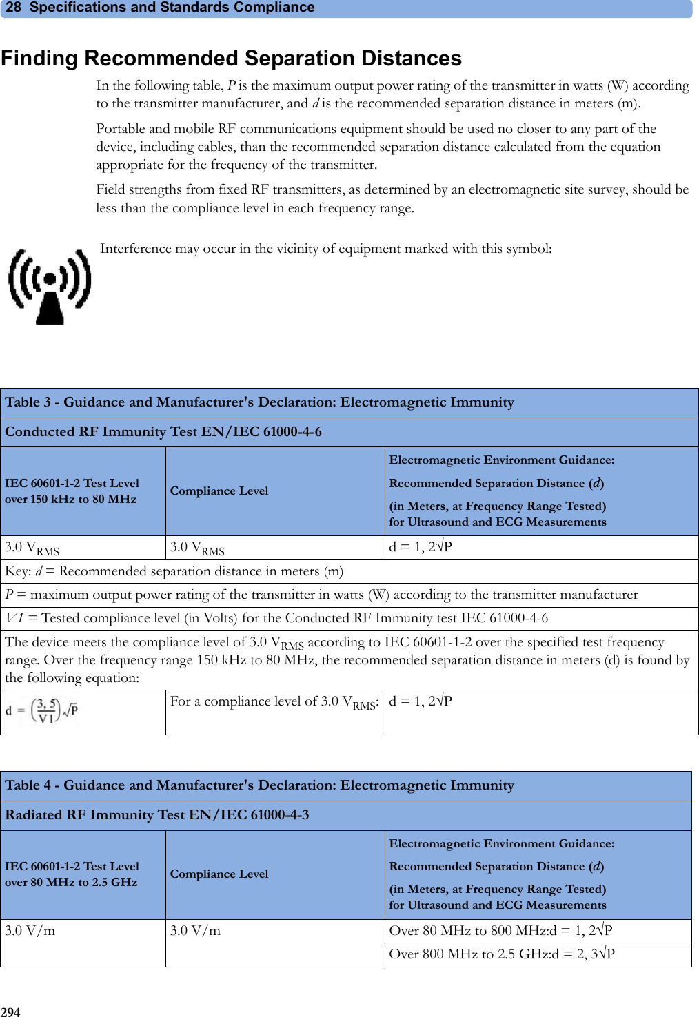
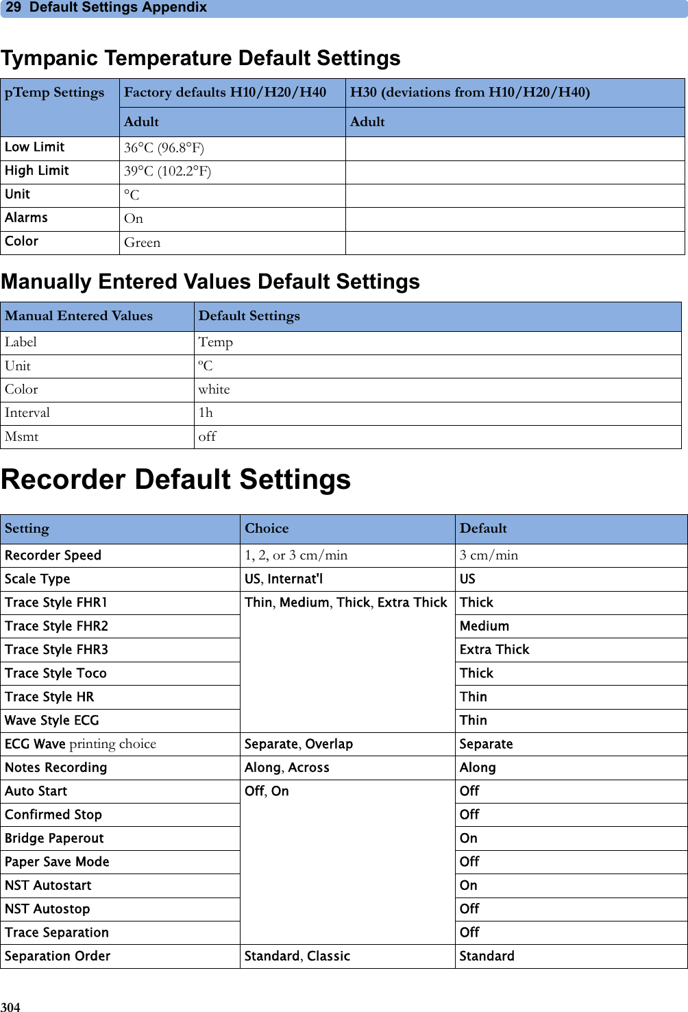
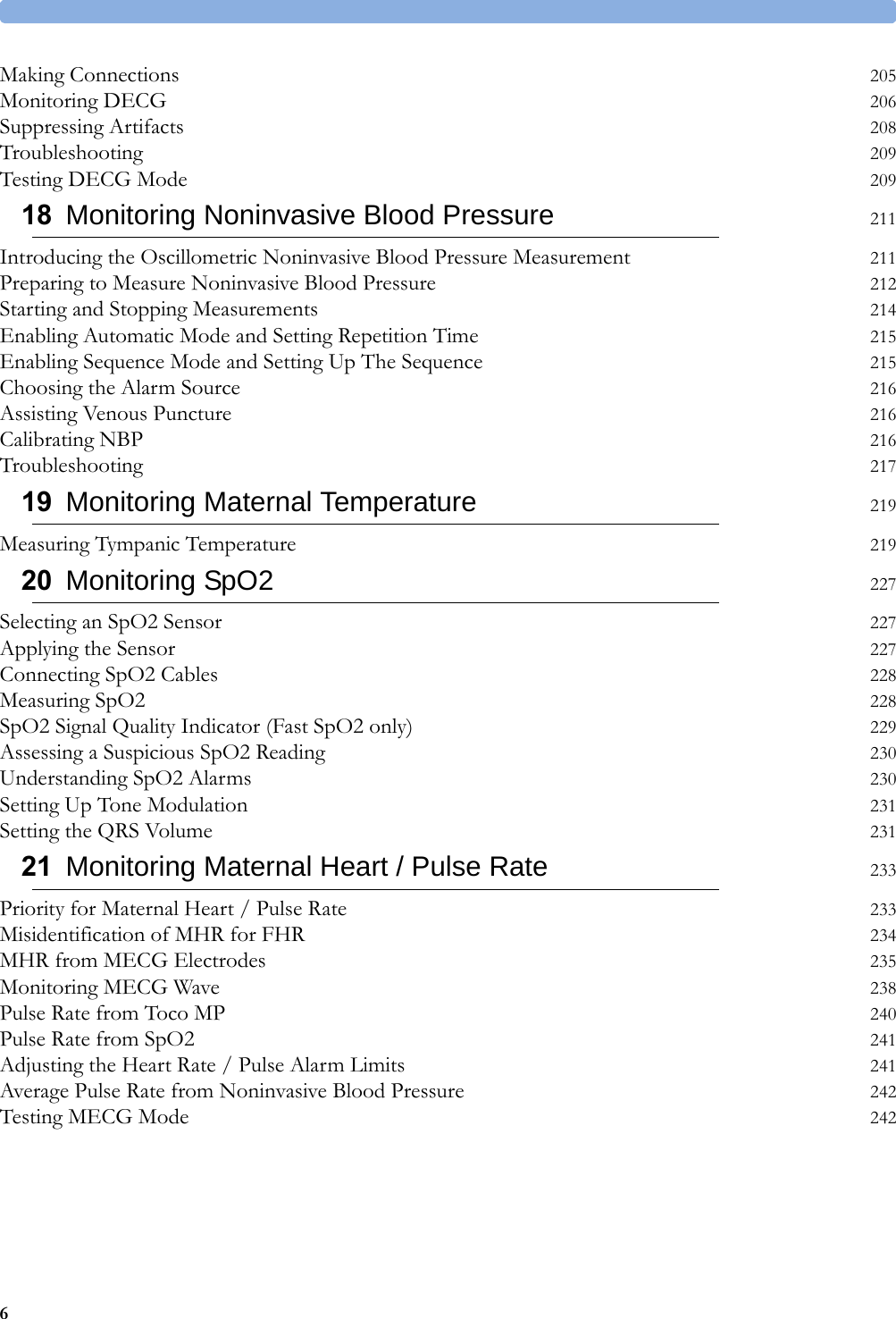
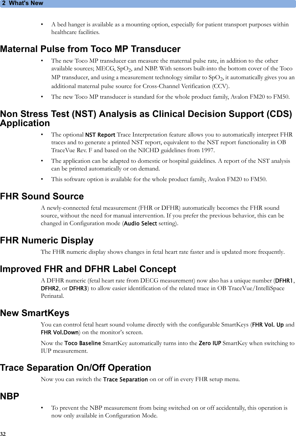
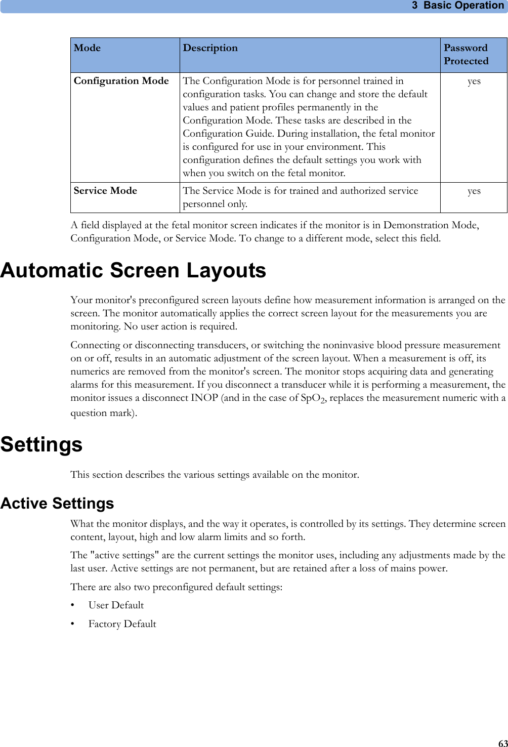
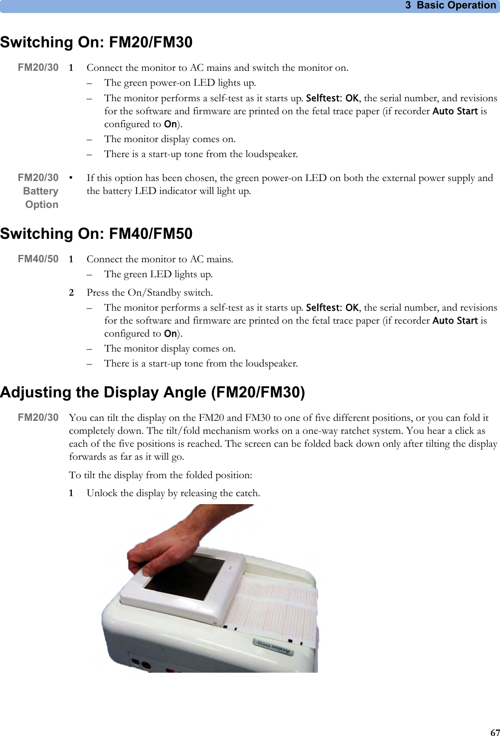
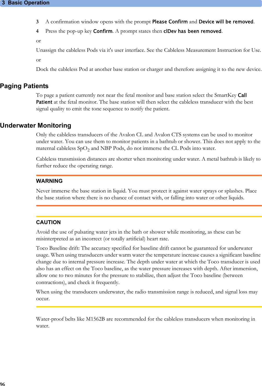
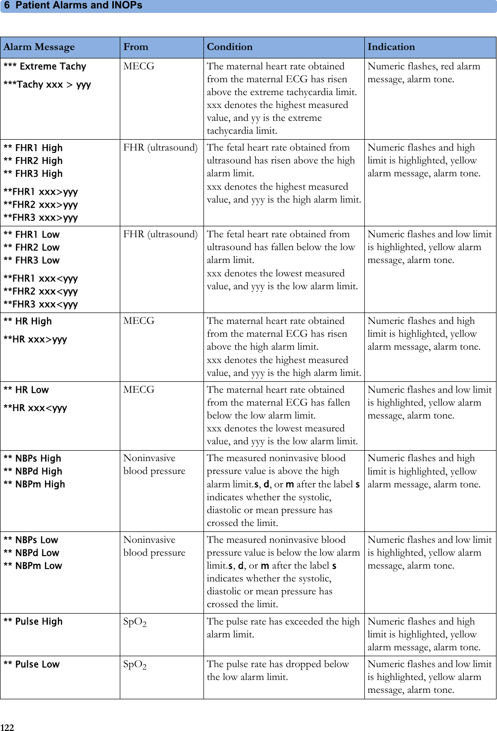
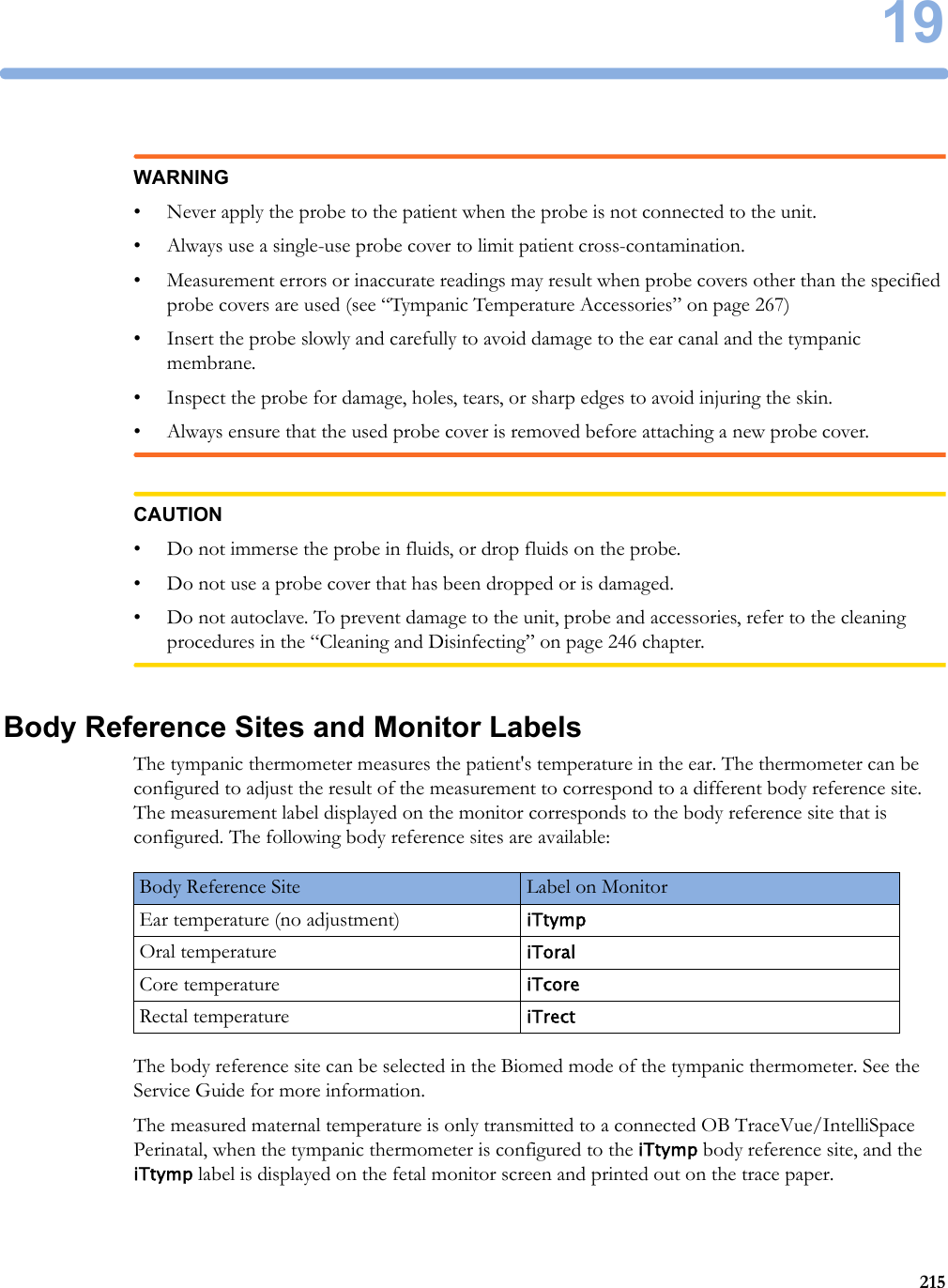
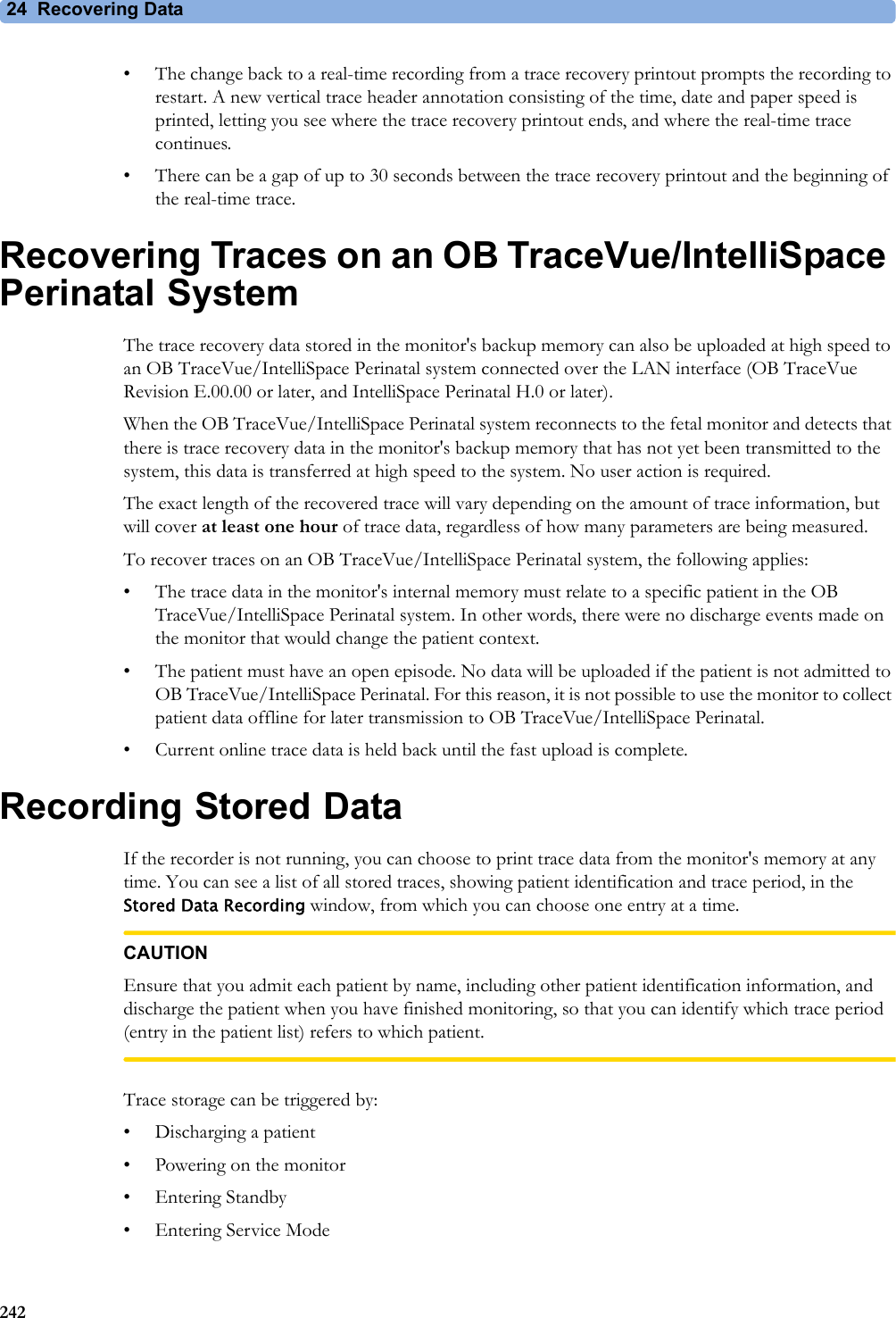
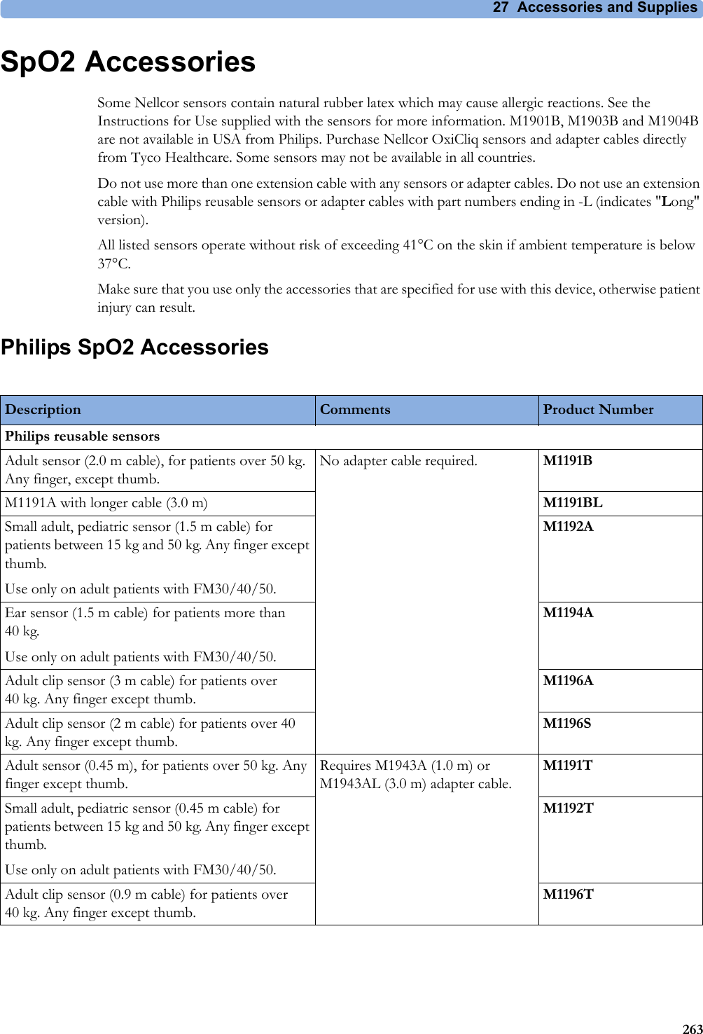
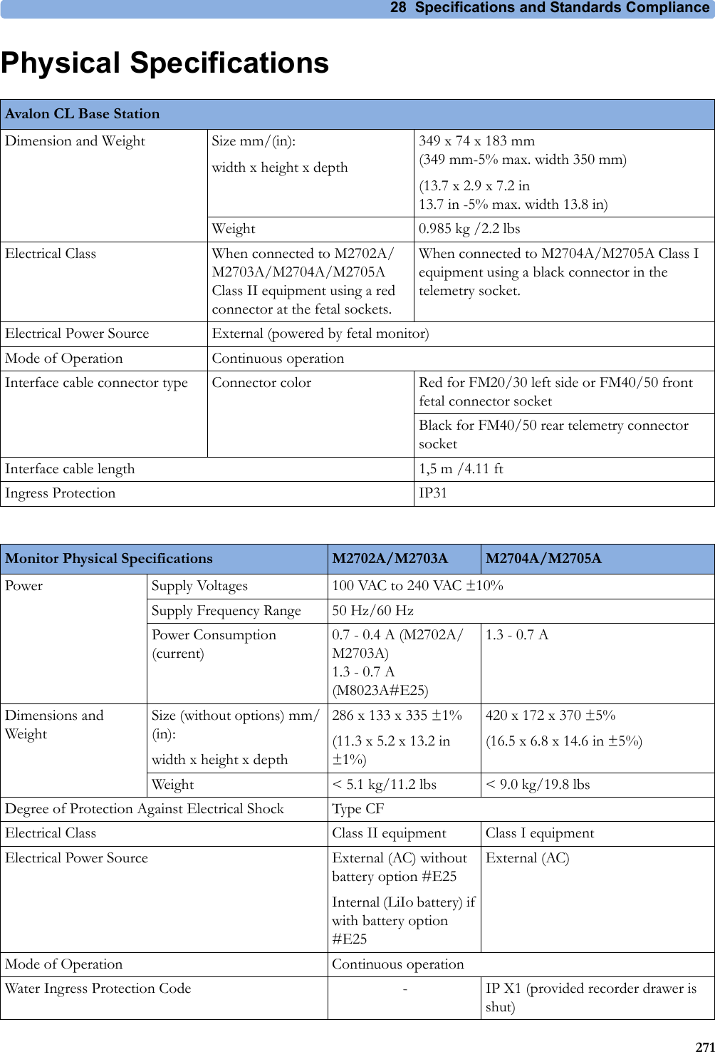
![28 Specifications and Standards Compliance300Socket for connecting Avalon CTS interface cable M2732-60001 or Avalon CL interface cable (with black connector, FM40/FM50)Identifies the year and month of manufacture.Symbol indication for non-ionizing radiation. Symbol indicating separate collection for waste electrical and electronic equipment.China ROHS CSA US mark GOST-R mark R&TTE Compliance Association: "Class 2 Device" Mark FCC ID Federal Communications Commission: FCC ID xxxxCMIIT ID Chinese Radio marking: CMIIT ID (China Ministry of Industry and Information Technology) Japanese Radio marking: Radio mark + "PMS Japan" (in Japanese) + Prod. No. + [R]-symbol + ID "Taiwan Radio Label" (NCC Logo) + ID Korea radio mark: KC logo, KCC ID number, and Conformity assessment informationIndustrial, Scientific, & Medical radio frequency band (Avalon CL frequency band used e.g. in the EU)Wireless Medical Telemetry Service (Avalon CL frequency band used e.g. in North America)Association Of Radio Industries And Businesses T108 (Avalon CL frequency band used e.g. in Japan)CE marking accompanied by the VDE NB number 0366IC-ID (Industry Canada ID)One IC-ID labeling for each built in radio: OBR, SRR Taiwan Radio Label (NCC Logo) + ID](https://usermanual.wiki/Philips-Medical-Systems-North-America/OBRTBV1.User-Manual/User-Guide-2013584-Page-300.png)