Philips Medical Systems North America OBRWRPBV1 Patient Monitoring User Manual ait fm manual
Philips Medical Systems North America Co. Patient Monitoring ait fm manual
Contents
- 1. User Manual Part 2
- 2. User Manual Part 1
User Manual Part 1

Instructions for Use
Avalon Fetal Monitor
FM20/30, FM40/50, Avalon CL
Release L.3 with Software Revision L.3x.xx
Patient Monitoring

3
1Table of Contents
1Introduction 9
Who this Book is For 9
Confirm Fetal Life Before Using the Monitor 10
Introducing the Avalon Family of Fetal Monitors 11
2What's New 21
What's New in Release L.3 21
What's New in Release J.3 23
3Basic Operation 27
Supported Measurements 28
Avalon FM20 and FM30 29
Avalon FM40 and FM50 30
Getting to Know Your Avalon FM20/FM30 31
Getting to Know Your Avalon FM40/FM50 34
Connecting the Monitor to AC Mains 36
Wired Transducers 36
Operating and Navigating 38
Operating Modes 44
Automatic Screen Layouts 45
Settings 45
Preparing to Monitor 48
After Monitoring 70
Switching the Monitor to the Standby Screen 71
Disconnecting from Power 71
Power On/Power Off Behavior 71
Monitoring After a Power Failure 72
Troubleshooting 72
4Cableless Monitoring 73
Avalon CL Transducer System 73
Basics of Cableless Systems 74
Twins and Triplets Support 75
Configuration of Cableless Systems 75
Getting to Know Your Avalon CL 76
Cableless Transducers 84
CL Pods 89
Calling Patients 93
Telemetry 94
Preparing to Monitor Cablelessly 100

4
Battery Lifetime Management 106
Patient Transport Within the Hospital 107
Underwater Monitoring 108
5FM20/30 Battery Option 109
External Power Supply M8023A 109
Using Batteries 110
Optimizing Battery Performance 113
Storing the Battery 115
Cableless Monitoring with FM20/30 Battery Option 116
Patient Transport Within the Hospital 116
6Alarms 117
Alarm Mode 118
Nurse Call Systems 118
Visual Alarm Indicators 119
Audible Alarm Indicators 119
Acknowledging Alarms 121
Acknowledging Disconnect INOPs 121
Alarm Reminder 122
Pausing or Switching Off Alarms 122
Alarm Limits 124
Reviewing Alarms 126
Latching Alarms 126
Testing Alarms 128
Alarm Behavior at Power On 128
7Patient Alarms and INOPs 129
Alarm Messages 129
Technical Alarm Messages (INOPs) 132
8Admitting and Discharging 147
Admit/Discharge on the Monitor 147
New Patient Check 149
OB TraceVue/IntelliSpace Perinatal 149
9Non-Stress Test Timer 151
Setting NST Autostart/Autostop 151
Viewing the NST Timer 151
Timer Expiry Notification 151
Accessing the NST Setup Pop-up Keys 152
10 Non-Stress Test Report 153
Setting Up an NST Report 153
NST Report Status Window 154
NST Criteria 157

5
11 Cross-Channel Verification (CCV) 159
Misidentification of Heart Rates 159
Cross-Channel Verification Functionality 160
Overview of Cross-Channel Comparisons 161
Coincidence Examples 162
Recommended Actions for Coincidence INOP 164
12 Monitoring FHR and FMP Using Ultrasound 165
Technical Description 165
Limitations of the Technology 166
Misidentification of Maternal HR as FHR 166
What You Need 166
Cableless Monitoring - Important Considerations 167
Preparing to Monitor 168
Selecting Fetal Heart Sound 169
Changing the Fetal Heart Sound Volume 170
Fetal Movement Profile 170
Troubleshooting 172
Additional Information 173
13 Monitoring Twin FHRs 183
Important Considerations 183
Monitoring Twins Externally 184
Monitoring Twins Internally 185
Separating FHR Traces 185
Troubleshooting 189
14 Monitoring Triple FHRs 191
Important Considerations 191
Monitoring Triplets 192
Separating FHR Traces 192
"Standard" Separation Order 193
"Classic" Separation Order 194
Switching Trace Separation On and Off 195
When Trace Separation is On 195
When Trace Separation is Off 195
Troubleshooting 196
15 Fetal Heart Rate Alarms 197
Changing Alarm Settings 197
Changing Signal Loss Delay 198
16 Monitoring FHR Using DECG 199
Misidentification of Maternal HR as FHR 199
What You Need 200
Making Connections 202

6
Monitoring DECG 202
Suppressing Artifacts 204
Troubleshooting 205
Testing DECG Mode 205
17 Monitoring Uterine Activity Externally 207
What You Need 207
External Toco Monitoring 208
Toco Sensitivity 208
Troubleshooting 208
18 Monitoring Uterine Activity Internally 211
What You Need 211
Internal (IUP) Monitoring 213
Troubleshooting 214
19 Monitoring aFHR, aHR, and aToco 215
Fetal Heart Rate aFHR 215
Uterine Activity aToco 216
What You Need 217
At the Monitor 217
Troubleshooting 218
20 Monitoring Maternal Heart / Pulse Rate 221
Priority for Maternal Heart / Pulse Rate 221
Misidentification of Maternal HR for FHR 222
Maternal HR from MECG Electrodes 222
Monitoring MECG Wave 225
Pulse Rate from Toco MP 227
Pulse Rate from SpO2 228
Adjusting the Heart Rate / Pulse Alarm Limits 228
Average Pulse Rate from Noninvasive Blood Pressure 228
Testing MECG Mode 229
21 Printing the ECG Waveform 231
22 Monitoring Noninvasive Blood Pressure 235
Introducing the Oscillometric Noninvasive Blood Pressure Measurement 235
Preparing to Measure Noninvasive Blood Pressure 237
Starting and Stopping Measurements 239
Enabling Automatic Mode and Setting Repetition Time 239
Enabling Sequence Mode and Setting Up the Sequence 240
Choosing the Alarm Source 240
Assisting Venous Puncture 241
Calibrating NBP 241
Troubleshooting 242

7
23 Monitoring SpO2 243
Selecting an SpO2 Sensor 243
Applying the Sensor 243
Connecting SpO2 Cables 244
Measuring SpO2 244
SpO2 Signal Quality Indicator (FAST SpO2 only) 245
Assessing a Suspicious SpO2 Reading 246
Understanding SpO2 Alarms 246
Setting Up Tone Modulation 247
Setting the QRS Volume 247
24 Monitoring Maternal Temperature 249
Measuring Tympanic Temperature 249
Entering Temperature Manually 254
25 Paper Save Mode for Maternal Measurements 255
26 Recovering Data 257
Recovering Traces on Paper 257
Recovering Traces on an OB TraceVue/IntelliSpace Perinatal System 258
Manually Recording Stored Data 258
27 Care and Cleaning 261
General Points 261
Cleaning and Disinfecting 262
Cleaning and Disinfecting Monitoring Accessories 263
Cleaning and Disinfecting the Tympanic Temperature Accessories 264
Cleaning and Disinfecting CL Transducers and CL Pods 264
Sterilizing 265
28 Maintenance 267
Inspecting the Equipment and Accessories 267
Inspecting the Cables and Cords 268
Maintenance Task and Test Schedule 268
Recorder Maintenance 269
Cleaning the Print Head 273
Returning Equipment for Repair 273
Disposing of the Monitor 274
29 Accessories and Supplies 275
Information on Latex 275
Avalon CL Base Station 275
Transducers 276
Fetal Accessories 276
Noninvasive Blood Pressure Accessories 278
SpO2 Accessories 280

8
Tympanic Temperature Accessories 285
Recorder Paper 285
Batteries 285
30 Specifications and Standards Compliance 287
Environmental Specifications 287
Physical Specifications 289
Interface Specifications 293
Performance Specifications 295
Recorder Specifications 308
External Displays: FM40/FM50 Only 310
Manufacturer's Information 310
Trademark Acknowledgment 310
Regulatory and Standards Compliance 311
Environment 321
Monitoring After a Loss of Power 321
ESU, MRI, and Defibrillation 321
Cardiac Pacemakers and Electrical Stimulators 322
Fast Transients/Bursts 322
Symbols on the System 322
31 Default Settings Appendix 327
Alarm and Measurement Default Settings 327
Recorder Default Settings 330
Index 333

1
9
1Introduction
Who this Book is For
This book is for trained healthcare professionals using the Avalon FM20, FM30, FM40, and FM50
fetal/maternal monitors, and the Avalon CL Transducer System. It describes how to set up and use the
monitor and transducers. Familiarize yourself with all instructions including warnings and cautions
before starting to monitor patients. Read and keep the Instructions for Use that come with any
accessories, as these contain important information about application, care, and cleaning that is not
repeated in this book.
If you have received this Instruction for Use because your fetal monitor has been upgraded to a newer
software version L.3, be aware that the standards compliance information contained in the
Instructions for Use for L.3 does not apply to your fetal monitor. Refer to your original Instructions
for Use for standards compliance information.
You should be:
• Trained in the use of fetal heart rate (FHR) monitors.
• Trained in the interpretation of FHR traces.
• Familiar with using medical devices and with standard fetal monitoring procedures.
For information on how to configure and service the monitor, see the Configuration Guide and the
Service Guides, or contact your authorized service provider.
Your monitor may not have all of the features and options described in this guide. The exact
appearance of the monitor may differ slightly from that shown in the illustrations.
This guide may contain descriptions of functionality and features that are not implemented in the
equipment currently shipped to Japan and/or of products that are not currently sold in Japan due to
limitations and restrictions under the applicable local laws and regulations in Japan. Please contact your
local sales representative and/or Philips Customer Support for details.
In this guide:
•A warning alerts you to a potential serious outcome, adverse event, or safety hazard. Failure to
observe a warning may result in death or serious injury to the user or patient.
•A caution alerts you to where special care is necessary for the safe and effective use of the
product. Failure to observe a caution may result in:
– minor or moderate personal injury,
– damage to the product or other property,
– possibly in a remote risk of more serious injury.

1 Introduction
10
•Monitor refers to the entire fetal/maternal monitor. Display refers to the physical display unit.
Screen refers to everything you see on the monitor's display, such as measurements, alarms,
patient data, and so forth.
FM30 • Whenever a monitor’s identifier appears to the left of a heading or paragraph, it means that the
information applies to that monitor only. Where the information applies to all models, no
distinction is made.
Avalon CL
Avalon CTS Whenever one of these identifiers appear to the left of a heading or paragraph, it means that the
information applies to that cableless transducer system. Where the information applies to both
systems, no distinction is made.
For installation instructions and technical description, see the corresponding Service Guide of the fetal
monitors.
Confirm Fetal Life Before Using the Monitor
Fetal monitoring technology available today is not always able to differentiate a fetal heart rate (FHR)
signal source from a maternal heart rate (MHR) source in all situations. Therefore, you should confirm
fetal life by independent means before starting to use the fetal monitor, for example, by palpation of fetal
movement or auscultation of fetal heart sounds using a fetoscope, stethoscope, or Pinard stethoscope.
If you cannot hear the fetal heart sounds, and you cannot confirm fetal movement by palpation,
confirm fetal life using obstetric ultrasonography. Continue to confirm that the fetus is the signal
source for the FHR during monitoring.
Be aware that:
• a maternal HR trace can exhibit features that are very similar to those of an FHR trace, even
including accelerations and decelerations. Do not rely solely on trace pattern features to identify a
fetal source.
• Fetal Movement Profile (FMP) annotations on a fetal trace alone may not always indicate that the
fetus is alive. The body of a deceased fetus can move and cause the monitor to annotate fetal body
movements.
Here are some examples where the maternal HR can be misidentified as the FHR.
When using an ultrasound transducer:
• It is possible to pick up maternal signal sources, such as the aorta or other large vessels.
• Misidentification may occur when the maternal HR is higher than normal (especially when it is
over 100 bpm).
When using a fetal scalp electrode:
• Electrical impulses from the maternal heart can sometimes be transmitted to the fetal monitor
through a recently deceased fetus via the spiral scalp electrode cable, appearing to be a fetal signal
source.
• The recorded maternal HR (and any artifact) can be misinterpreted as an FHR (especially when it
is over 100 bpm).
When Fetal Movement Profile (FMP) is enabled:
FMP annotations in the absence of fetal life may be a result of:
• Movement of the deceased fetus during or following maternal movement.
• Movement of the deceased fetus during or following manual palpation of fetal movement
(especially if the pressure applied is too forceful).

1 Introduction
11
• Movement of the ultrasound transducer.
• The ultrasound transducer detecting a maternal movement source, such as the mother coughing.
See also “Monitoring FHR and FMP Using Ultrasound” on page 165 and “Monitoring FHR Using
DECG” on page 199.
To reduce the possibility of mistaking the maternal HR for an FHR, it is recommended that you
monitor both maternal and fetal heart rates. The monitor's cross-channel verification (CCV) feature
can help by automatically detecting when a maternal HR coincides with an FHR. For further details,
see “Cross-Channel Verification (CCV)” on page 159.
Introducing the Avalon Family of Fetal Monitors
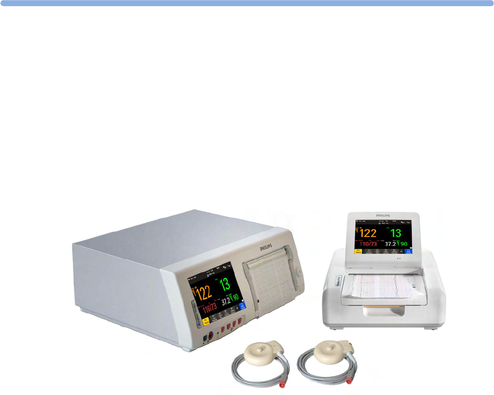
The Avalon family of fetal monitors consists of the Avalon FM20, FM30, FM40, and FM50. While the
FM20/FM30 and the FM40/FM50 have different form factors, the method of operation is very
similar for all monitors. The Avalon fetal monitors also share transducers, accessories, software, and
are compatible with the Avalon CL, and Avalon CTS Fetal Transducer Systems.
Intended Use
The Philips Avalon FM20 (M2702A), FM30 (M2703A), FM40 (M2704A), and FM50 (M2705A) fetal/
maternal monitors are intended for:
• noninvasive monitoring of fetal heart rates and movements.
• noninvasive monitoring of maternal heart rates, maternal pulse rates, uterine activity, maternal
noninvasive blood pressure, maternal oxygen saturation, and maternal temperature.
• invasive monitoring of direct fetal heart rate, intrauterine pressure, and for displaying and
recording of fetal and maternal electrocardiogram (ECG) (FM30 and FM50 only).
• displaying, storing, and recording patient data and parameter values, and for generating alarms
from fetal and maternal parameters.
• transmitting patient data and parameter values to a patient information and surveillance system.
• use by trained health care professionals.
• use in antepartum testing areas, in labor and delivery rooms, and during postpartum recovery in
the hospital environment. They are not intended for use in intensive care units or operating rooms.
• monitoring in a bath or shower (Avalon CL cableless transducers Toco+ MP, Ultrasound, and
ECG/IUP only).
• transport situations in healthcare facilities, for healthcare facilities outside hospitals, such as
doctors’ offices, and for use in private households (FM20 and FM30 only).

1 Introduction
12
WARNING
The fetal/maternal monitors are not intended for:
• use during defibrillation, electro-surgery, or magnetic resonance imaging (MRI).
• Electrocardiography (ECG) measurements on patients connected to electrical stimulator or with
cardiac pacemakers.
• use of the invasive measurements IUP and fetal DECG, use of the patient module (M2738A) and
use of the Avalon CL system in domestic establishments, and those connected directly to the
public low-voltage supply network that supplies buildings used for domestic purposes.
• measuring the maternal temperature using the tympanic thermometer (866149) in private
households.
WARNING
No modification of the fetal monitors, transducers, and the Avalon CL base station is allowed.
CAUTION
U.S. federal law restricts this device to sale by, or on the order of, a physician.
All users must read the Instructions for Use before working with the fetal monitor. Disregarding the
contents of the Instructions for Use is considered abnormal use.

1 Introduction
13
Indications for Use
Avalon Fetal/Maternal Monitor FM20
Indicated for use by trained health care professionals whenever there is a need for monitoring the
physiological parameters uterine activity, heart rate, oxygen saturation, noninvasive blood pressure,
pulse rate, and temperature of pregnant women, and the fetal heart rates of single fetuses, twins, and
triplets in labor and delivery rooms, in antepartum testing areas, in private households and during
transports in healthcare facilities.
Avalon Fetal/Maternal Monitor FM30
Indicated for use by trained health care professionals whenever there is a need for monitoring the
physiological parameters uterine activity, heart rate, electrocardiography (ECG), oxygen saturation,
noninvasive blood pressure, and pulse rate, and temperature of pregnant women, and the fetal heart
rates of single fetuses, twins, and triplets in labor and delivery rooms, in antepartum testing areas, in
private households and during transports in healthcare facilities.
Avalon Fetal/Maternal Monitor FM40
Indicated for use by trained health care professionals whenever there is a need for monitoring the
physiological parameters uterine activity, heart rate, oxygen saturation, noninvasive blood pressure,
and pulse rate, and temperature of pregnant women, and the fetal heart rates of single fetuses, twins,
and triplets in labor and delivery rooms and in antepartum testing areas.
Avalon Fetal/Maternal Monitor FM50
Indicated for use by trained health care professionals whenever there is a need for monitoring the
physiological parameters uterine activity, heart rate, electrocardiography (ECG), oxygen saturation,
noninvasive blood pressure, and pulse rate, and temperature of pregnant women, and the fetal heart
rates of single fetuses, twins, and triplets in labor and delivery rooms and in antepartum testing areas.
Safety Information
In this guide:
• A warning alerts you to a potential serious outcome, adverse event or safety hazard. Failure to
observe a warning may result in death or serious injury to the user or patient.
• A caution alerts you to where special care is necessary for the safe and effective use of the product.
Failure to observe a caution may result in minor or moderate personal injury or damage to the
product or other property, and possibly in a remote risk of more serious injury.

1 Introduction
14
Electrical Hazards
WARNING
Electrical shock hazard: Do not open the monitor housing. Refer all servicing to qualified service
personnel.
• Always use the supplied power cord with the earthed mains plug to connect to an earthed AC
mains socket. Never adapt the mains plug from the fetal monitor to fit an unearthed AC mains
socket.
• Do not use AC mains extension cords or multiple portable socket-outlets.
•FM20/FM30 only: The protective earth conductor is required for EMC purposes. It has no
protective function against electric shock. Double and/or reinforced insulation protects this
device against electric shock.
• Do not connect any devices that are not supported as part of a system.
• Any non-medical device placed and operated in the patient’s vicinity must be powered with an
approved isolation transformer that ensures mechanical fixing of the power cords, and covering of
any unused power outlets.
• The fetal/maternal monitor is NOT intended for use during defibrillation, electro-surgery, or
MRI. Remove all transducers, sensors, and accessories before performing electro-surgery,
defibrillation, or MRI, otherwise harm to the patient or the user can result.
• Do not touch the charging contacts for the cableless transducers at the Avalon CL base station
while you are touching the patient.
Leakage currents: If several items of equipment used to monitor a patient are interconnected, the
resulting leakage current may exceed allowable limits.
Radio Frequency Interference
WARNING
• Short range radio connections are subject to interruption due to interference from other radio
sources in the vicinity, including microwaves, bluetooth devices, WLAN devices (802.11b,g,n), and
cordless phones. Depending on the strength and duration of the interference, the interruption may
occur for an extended period. A loss of connection, due to moving out-of-range, interference, or
for other reasons, is indicated with a No Host Monitoring INOP (here the host is the fetal monitor)
on the IntelliVue CL NBP or CL SpO2 Pods, or a No Host Monitoring, or cl NBP Disconnect, or cl
SpO₂ Disconnect INOP at the fetal monitor. Correct channel configuration is important, refer to
the Service Guides and the Configuration Guide for details.
• To avoid magnetic interference affecting the mode of the pacemaker, ensure that the
Avalon CL base station does not come into close contact with implanted pacemakers.
• This equipment generates, uses, and radiates radio-frequency energy, and if it is not installed and
used in accordance with its accompanying documentation, may cause interference to radio
communications. Operation of this equipment in a residential area may cause interference, in
which case the users must take whatever measures may be required to correct the interference.
• Do not use cordless/mobile phones or any other portable RF communication system within the
patient vicinity, or within a 1.0 m radius of any part of the fetal monitoring system.

1 Introduction
15
• For paced patients: The radiated SRR power of the CL SpO2, CL NBP Pods, CL F&M Pod, and
the CL Wide Range Pod, and other sources of radio-frequency energy, when used in very close
proximity of a pacemaker, might be sufficient to interfere with pacemaker performance. Due to
shielding effects of the body, internal pacemakers are somewhat less vulnerable than external
pacemakers. However, caution should be exercised when monitoring paced patients.
• In order to minimize the possibility of interference, avoid positioning and wearing the Cableless
Measurement Devices in very close proximity to a pacemaker. Consult the pacemaker
manufacturer for information on the RF susceptibility of their products.
Use Environment
WARNING
Explosion Hazard:
• Do not use in the presence of flammable anesthetics, such as a flammable anesthetic mixture with
air, oxygen, nitrous oxide, or in oxygen rich environment. Use of the devices in such an
environment may present an explosion hazard.
• Use only Philips batteries part number M4605A with the FM20 or FM30 with battery option. Use
of a different battery may present a risk of fire or explosion.
Environmental Specifications:
• The performance specifications for the monitors, measurements, and accessories apply only for
use within the temperature, humidity, and altitude ranges specified in “Environmental
Specifications” on page 287.
Liquid Ingress:
• Do not operate the monitor if it is wet. If you spill liquid on the monitor, contact your service
personnel, or Philips service engineer.
• Never immerse the fetal monitor or the CL base station in liquid. You must protect them against
water sprays or splashes. Place the fetal monitor and the CL base station where there is no chance
of contact with, or falling into water or other liquids.
• Do not perform underwater monitoring (for example, in a bath or shower) using wired
transducers.
• The CL Fetal & Maternal Pod is not intended for underwater monitoring. The contacts between
the CL Fetal & Maternal Pod and the electrode patch have to be kept dry at all times. The CL Fetal
& Maternal Pod mounted on the electrode patch, can be worn underneath a shower, as long as the
CL Fetal & Maternal Pod stays mounted. Radio transmissions in the shower may be compromised.
Heat Exposure:
• Do not dry equipment using heating devices such as heaters, ovens (including microwave ovens),
hair dryers, and heating lamps.
• Do not put equipment or accessories in autoclave (for sterilization).
Positioning Equipment:
• The device should not be used adjacent to, or stacked with, other equipment unless otherwise
specified.

1 Introduction
16
Prohibited Environments:
• The monitors and their transducers, Pods, and accessories are not intended for use in an MRI
environment or in an oxygen-enriched environment (for example, hyperbaric chambers).
Alarms
WARNING
• Do not rely exclusively on the audible alarm system for fetal monitoring. Adjustment of alarm
volume to a low level or off during monitoring may result in a dangerous situation. Remember that
the most reliable method of fetal monitoring combines close personal surveillance with correct
operation of monitoring equipment.
• Alarm systems of the monitor and those of the connected obstetrical information and surveillance
system are independent and not synchronized.
•In
INOP only mode, no fetal/maternal patient alarms are enabled or indicated.
Accessories
WARNING
Philips' approval: Use only Philips-approved accessories. Using non-Philips-approved accessories
may compromise device functionality and system performance, and cause a potential hazard.
Reuse: Never reuse disposable transducers, sensors, accessories, and so forth, that are intended for
single use, or single patient use only. Reuse may compromise device functionality and system
performance, and cause a potential hazard.
Electromagnetic compatibility: The use of accessories, transducers, and cables other than those
specified may result in increased electromagnetic emissions or decreased electromagnetic immunity of
the device.
Damage: Do not use a damaged sensor or one with exposed electrical contacts.
Cables and tubing: When connecting devices for acquiring measurements, always position cables and
NBP tubing carefully to avoid entanglement or potential strangulation.

1 Introduction
17
Security Information
Protecting Personal Information
Protecting personal health information is a primary component of a security strategy. Each facility
using the monitors must provide the protective means necessary to safeguard personal information
consistent with country laws and regulations, and consistent with the facility’s policies for managing
this information. Protection can only be realized if you implement a comprehensive, multi-layered
strategy (including policies, processes, and technologies) to protect information and systems from
external and internal threats.
As per its intended use, the patient monitor operates in the patient vicinity and contains personal and
sensitive patient data. This also includes the trace print-outs at the monitor.
The monitor also includes controls to allow you to adapt the monitor to the patient's care model.
To ensure the patient's safety and protect their personal health information, you need a security
concept that includes:
•Physical security access measures - access to the monitor must be limited to authorized users.
It is essential that you consider physical security measures to ensure that unauthorized users
cannot gain access.
•Operational security measures - for example, ensuring that patients are discharged after
monitoring in order to remove their data from the monitor.
•Procedural security measures - for example, assigning only staff with a specific role the right to
use the monitors.
In addition, any security concept must consider the requirements of local country laws and regulations.
Always consider data security aspects of the network topology and configuration when connecting
patient monitors to shared networks. Your medical facility is responsible for the security of the
network, where sensitive patient data from the monitor may be transferred.
When a monitor is returned for repair, disposed of, or removed from your medical facility for other
reasons, always ensure that all patient data is removed from the monitor by ending monitoring for the
last patient (see “Discharging a Patient” on page 148). Also select Erase All in the Stored Data Recording
menu, to erase all stored data.
NOTE
Log files generated by the monitors and measurement modules are used for system troubleshooting
and do not contain protected health data.
About HIPAA Rules
If applicable, your facility’s security strategy should include the standards set forth in the Health
Insurance Portability and Accountability Act of 1996 (HIPAA), introduced by the United States
Department of Health and Human Services. You should consider both the security and the privacy
rules and the HITECH Act when designing policies and procedures. For more information, please
visit:
http://www.hhs.gov/ocr/privacy/

1 Introduction
18
About the EU Directives
If applicable, your facility’s security strategy should include the practices set forth in the Directive on
the protection of individuals with regard to the processing of personal data and on the free movement
of such data (Directive 95/46/EC of the European Parliament and of the Council of
24 October 1995). In addition, your facility should also take into account any additional, more
stringent standards put forward by any individual EU countries; that is, Germany, France, and so on.
Philips Product Security Policy Statement
Additional security and privacy information can be found on the Philips product security web site at:
http://www.healthcare.philips.com/main/support/equipment-performance/product-security/
index.wpd
Manufacturer Disclosure Statement for Medical Device Security – MDS2
You can view the Manufacturer Disclosure Statements for Medical Device Security (MDS2) for
specific devices at:
http://www.healthcare.philips.com/main/support/equipment-performance/product-security/
index.wpd
Overview of System Components
The Avalon CL system consists of the Avalon CL base station, the Avalon CL transducers, the
Avalon CL Fetal & Maternal Pod, the CL Wide Range Pod, and the IntelliVue CL Pods.
The IntelliVue CL Pods are only used for maternal measurements within the Avalon CL solution.
The following table provides an overview of all the devices.
Avalon FM20/FM30 and FM40/
FM50
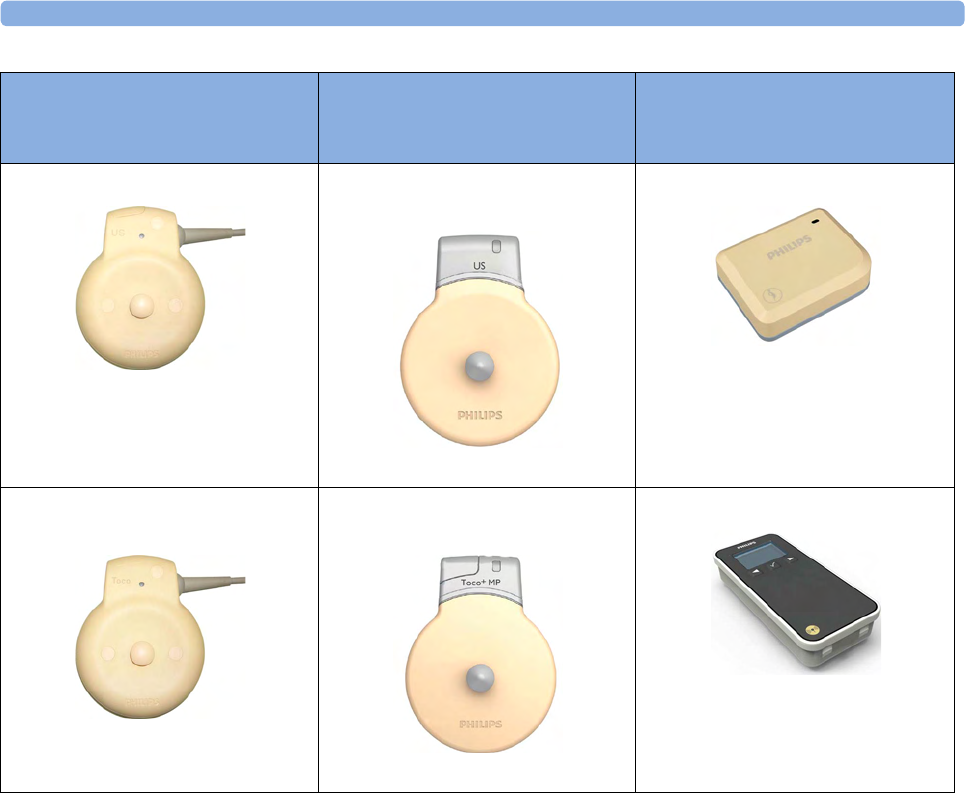
Wired Transducers
Avalon CL Base Station
Avalon CL Transducers
CL Pods
FM20/FM30
M2702A and M2703A
FM40/FM50
M2704A and M2705A
Avalon CL Base Station
866074
1 Introduction
19
US transducer (wired)
M2736A
Avalon CL US Transducer
(cableless)
866076
Avalon CL Fetal & Maternal Pod
866488
Toco/ Toco MP transducer
(wired)
M2734A and M2734B
Avalon CL Toco+ MP Transducer
(cableless)
866075
Avalon CL Wide Range Pod
866487
Avalon FM20/FM30 and FM40/
FM50
Wired Transducers
Avalon CL Base Station
Avalon CL Transducers
CL Pods
1 Introduction
20
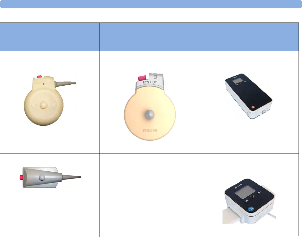
Toco+ transducer with ECG/IUP
capability (wired)
M2735A
Avalon CL ECG/IUP Transducer
(cableless)
866077
IntelliVue CL NBP Pod
(cableless)
865216
Patient Module for ECG/IUP
M2738A
IntelliVue CL SpO2 Pod
(cableless)
865215
Avalon FM20/FM30 and FM40/
FM50
Wired Transducers
Avalon CL Base Station
Avalon CL Transducers
CL Pods

2
21
2What's New
This section lists the most important new features and improvements to the fetal monitors and their
user interface introduced with Release L.3.
You may not have all of these features, depending on the fetal monitor configuration purchased.
What's New in Release L.3
Avalon CL Fetal & Maternal Pod
The Avalon CL Fetal & Maternal Pod is an extension of the Avalon CL solution. The Avalon
CL Fetal & Maternal Pod is used together with a single use patch with five abdominal electrodes. Prior
to use, the Avalon CL Fetal & Maternal Pod is charged and assigned at the Avalon CL base station.
The Avalon CL Fetal & Maternal Pod is used with singleton pregnancies. This solution provides
especially benefits to patients with high body mass index (BMI), although it can be used for all patients.
The Avalon CL Fetal & Maternal Pod includes the following features:
• The Avalon CL Fetal & Maternal Pod measures fetal heart rate (aFHR), maternal heart rate (aHR),
and uterine activity (aToco) from electrical signals.
•The
cl F&M Electrode Status window at the monitor gives an overview of the current electrode
contact status, when the CL Fetal & Maternal Pod is placed on the electrode patch, and the patch,
and the electrodes are applied to the patient's abdominal skin. The window can be opened by
selecting the new SmartKey cl F&M Status, or selecting the corresponding function in the main
setup menu.
• The Avalon CL Fetal & Maternal Pod and the CL Wide Range Pod are assigned at the CL base
station in the same easy way as the IntelliVue CL Pods.
• The functions Finder LED and Call Patient work also with the Avalon CL Fetal & Maternal
Pod.
See “Avalon CL Fetal & Maternal Pod” on page 21, “CL Fetal & Maternal Electrode Patch” on
page 91, “Applying the CL Fetal & Maternal Patch and Pod” on page 100, and “CL Pod Assignment”
on page 99.

2 What's New
22
Avalon CL Wide Range Pod
The Avalon CL Wide Range Pod is an extension of the Avalon CL solution. The Avalon CL Wide
Range Pod extends the signal range of the cableless measurements. It transmits the cableless
measurement signals via the hospital WLAN/WiFi to the fetal monitors. Wearing the CL Wide Range
Pod, the patient can walk freely within the hospital's WLAN/WiFi range during monitoring. Prior to
use, the Avalon CL Wide Range Pod is charged and assigned at the Avalon CL base station.
• A new WLAN symbol is printed on the trace to indicate the use of an assigned and active Avalon
CL Wide Range Pod.
• During monitoring with an active Avalon CL Wide Range Pod, the sound from the fetal heart rate
is replaced by an artificial QRS sound (when the patient is monitored with a CL US transducer or
CL F&M Pod).
See “CL Wide Range Pod” on page 91.
Dawes/Redman
Dawes/Redman is a method of fetal monitoring trace interpretation for helping to assess fetal
well-being. The algorithm based on the Dawes/Redman criteria uses the parameters fetal heart rate,
gestational age, fetal movement, accelerations and decelerations, and long, and short term variability to
generate a report.
Not available in the USA and territories relying on FDA market clearance.
Support of XDS Remote Display
The fetal monitor software supports the IntelliVue XDS “Remote Display” functionality only in
combination with IntelliSpace Perinatal revision K or higher. From the user interface of the
IntelliSpace Perinatal system, you can access all screen-operable functions of the currently connected
fetal monitor. These functions include for example, starting and stopping physiological measurements,
changing measurement modes, changing alarm limits, and silencing alarms.
New Alarm Behavior of CL Battery Empty INOP
The CL <xxx> Battery Empty INOP issued by the CL devices and the fetal monitor has a new alarm
behavior:
• At the fetal monitor, it is issued now with a cyan INOP alarm and tone.
• At CL devices (CL transducers and CL Pods), it is issued now with a tone.
See “Patient Alarms and INOPs” on page 129.
Using CL Pods with FM20/30 #E25
The CL Pods can now also be used with a battery operated FM20 or FM30 (option #E25). The
CL Pods can be assigned and activated. The CL F&M Pod can also be charged.
See “Using Batteries” on page 110.
Entering Notes - Type a Note
In the menu Enter Note, it is now possible to enter a note manually, instead of selecting one of the
pre-configured notes. To enter a note, select the new menu item Type a note. A window with a touch
keypad opens. The typed note can be up to 30 characters long.
See “Typing Notes” on page 70.

2 What's New
23
What's New in Release J.3
Avalon CL Transducer System
The Avalon CL Transducer System provides cableless monitoring with the Avalon FM20/FM30 and
FM40/FM50 with the same functionality and performance as the wired measurement devices (e.g.
twin and triplets monitoring). The Avalon CL Transducer System has a straight-forward handling and
operating concept. The CL transducers are assigned by simply docking them at the CL base station, no
further configuration is necessary.
The Avalon CL Transducer System includes the following features:
• Cableless monitoring of twins and triplets (see “Monitoring Twin FHRs” on page 183 and
“Monitoring Triple FHRs” on page 191)
• Cableless maternal measurement Pods CL SpO2 and CL NBP (see “IntelliVue CL Pods” on
page 92)
• Maternal pulse from a CL Toco+ MP (Smart Pulse) transducer (see “Monitoring Maternal Heart /
Pulse Rate” on page 221)
• A cableless ECG/IUP transducer measuring IUP or fetal/maternal ECG (see “Monitoring
MECG Wave” on page 225 and “Monitoring FHR Using DECG” on page 199)
• Watertight cableless transducers that can be used to monitor in water (see “Underwater
Monitoring” on page 108)
• Patient call that pages an ambulating mother with an audible signal emitted by the worn CL
transducers (see “Calling Patients” on page 93)
• Out-of-range audible signal emitted by the worn CL transducers to inform an ambulating mother
that she has reached the limit of the active signal area-of-reach (see “Standard Radio Range of CL
Transducers” on page 87)
• A transducer finder LED on all CL transducers to help identify the assigned transducer (see
“Cableless Transducer LED Indication” on page 86)
Support For Use of Maternal Cableless Measurement Devices
The IntelliVue CL measurement Pods are patient-worn, battery-powered measurement devices for
SpO2 and NBP. The devices provide measurement values on the built-in display and communicate
them to the fetal monitor using the wireless short range radio (SRR) interface of the Avalon CL base
station (see “IntelliVue CL Pods” on page 92).
Maternal Temperature Measurement
To measure maternal temperature, the new optional tympanic thermometer (866149) is available for
the Avalon fetal monitors (“Monitoring Maternal Temperature” on page 249). The measurement data
is:
• documented and printed out at the local recorder, and transmitted to the obstetrical information
and surveillance system.
• displayed as a numeric on the screen.

2 What's New
24
Manually Entered Maternal Temperature Measurements
Manually measured temperatures can be entered at the fetal monitor. They are displayed as a numeric
on screen, and are printed out on the recorder trace (“Monitoring Maternal Temperature” on
page 249).
SpO2 Recordings and Transmissions
SpO2 annotation on local recorder
You can now configure the interval for printing the SpO2 numeric values on the recorder trace. With
the new configuration setting Record on Trace, you can set the interval to 1 or 5 minutes.
SpO2 transmission to an obstetrical information and surveillance system
You can now configure the interval for transmitting the SpO2 numeric values to an obstetrical
information and surveillance system. With the new configuration setting Send to OB Sys, you can set the
interval to 1 or 5 minutes.
New Design for the User Interface
The user interface for the fetal monitors has been redesigned to bring the presented information into
the foreground, letting the structural elements such as keys and frames retreat into the background.
Additionally special regard was given to making the "look and feel" similar to that of standard software
products (see “Operating and Navigating” on page 38).
New SmartKeys
•The Start ECG SmartKey and menu item is renamed to Record ECG.
•With the Call Patient SmartKey, you can now page patients who are ambulating wearing Avalon CL
transducers.
•With the Tele Info SmartKey, you can call up the Tele Info window on the fetal monitor display. In
the Tele Info window, you can control and view the status of the cableless transducers from the
connected Avalon CL base station.
•With the Enter Temp SmartKey, a pop-up window opens showing a numeric pad for entering
manually measured maternal temperature values.
•With the NBP Modes SmartKey, you can access the NBP Mode selection and setup, and can directly
start and stop a measurement.
•With the QuickAdmit SmartKey, you can quick admit a patient to the monitor.
All new SmartKeys are optional, and have to be configured in Configuration Mode for use (see
“SmartKeys” on page 42).
Coincidence INOP Tone
When the cross-channel verification detects that the signal of the maternal heart rate coincides with the
fetal heart rate, the Coincidence INOP is now issued with a tone at the fetal monitor. The Coincidence
INOP tone has a configurable delay see “Cross-Channel Verification (CCV)” on page 159.

2 What's New
25
Increased Internal Back-up Memory
The internal back-up memory is now able to store traces and data from at least the last 3.5 hours with
the software revision J.3, and minimum 7 hours with the new mainboard hardware revision A 00.18
(see “Manually Recording Stored Data” on page 258 and “Recovering Data” on page 257).
Dual System Interface Support
If the fetal monitor is connected via a LAN connection to OB TraceVue/IntelliSpace Perinatal, the
RS232 interface can be used independently to connect e.g. an EMR system on read-only basis. The
system connected to the RS232 interface in this case cannot alter any data (such as ADT data, or the
date and time setting), or interfere with functions of the monitor, but is able to read output data. The
obstetrical information and surveillance system connected via LAN has priority.
USB Interface
An optional USB interface allows the use of bar code readers and input devices such as a keyboard, or
mouse (see “Getting to Know Your Avalon FM20/FM30”/“Bottom” on page 32 and “Getting to
Know Your Avalon FM40/FM50”/“Rear” on page 33).
Flexible Nurse Call Interface
An optional Flexible Nurse Call interface allows the connection of a nurse call device to the fetal
monitors (see “Getting to Know Your Avalon FM20/FM30”/“Bottom” on page 32 and “Getting to
Know Your Avalon FM40/FM50”/“Rear” on page 33).
DHCP Support
The DHCP support offers an alternative to BOOTP. DHCP (Dynamic Host Configuration Protocol)
enables the fetal monitors to request an IP address (internet protocol address) from the connected
network (OB TraceVue/IntelliSpace Perinatal) automatically.
Data Export Support
You can now export measurement values from the monitor to other devices via the LAN interface, or
with the optional MIB RS232 interface (see “Getting to Know Your Avalon FM20/FM30”/“Bottom”
on page 32 and “Getting to Know Your Avalon FM40/FM50”/“Rear” on page 33).
NBP Configurable Measurement Sequence
Up to four measurement cycles can be set up which will run consecutively. For each cycle, you can set
the number of measurements and the interval between them. By setting the last cycle to run
continuously, you can have regular measurements continue after the sequence has run (see “Enabling
Sequence Mode and Setting Up the Sequence” on page 240.
Alarms Enhancements
In addition to the standard cyan INOPs, some INOPs can now be configured as red or yellow INOPs
to provide a severity indication (ECG Leads Off, Cuff Overpress, Cuff NotDeflated, Battery Empty, No
Pulse) (see “Alarms” on page 117).

2 What's New
26
Alarm Reminder
In Configuration Mode, you can set now an Alarm Reminder. The Alarm Reminder emits an audible
reminder of alarm conditions that remain active after the alarm is acknowledged. This reminder may
take the form of a repetition of the alarm tone for a limited time, or an unlimited repetition of the
alarm tone (this is the same as a new alarm). The interval between silencing the alarm and sounding the
reminder tone can be set to one, two, or three minutes (see “Alarm Reminder” on page 122).
Auto Free
In Configuration Mode, you can now set an Auto Free setting which discharges a patient automatically
when the fetal monitor has been powered off, or is in standby mode for a set time. Only the
demographic patient data is deleted, the trace data is not affected.
3
27
3Basic Operation
This chapter gives you an overview of the monitor and its functions. It tells you how to perform tasks
that are common to all measurements (such as entering data, switching on a measurement, changing
some monitor settings, and setting up the recorder). The alarms section gives an overview of alarms.
The remaining sections tell you how to perform individual measurements, and how to care for and
maintain the equipment.

3 Basic Operation
28
Supported Measurements
Different measurements for the same physiological parameter may have a different appearance on the
trace, due to: variability (HR), averaging, delay, amplitude, or artifacts. Before interpreting the trace,
regard the fetal monitor setup and transducers used.
The following Fetal measurements are supported:
The following Maternal measurements are supported:
Measurements FM20 FM30 FM40 FM50
Fetal Heart Rate (FHR) via
US (including Twins)
Standard Standard Standard Standard
Triple FHR via US Optional Optional Optional Optional
dFHR via Direct ECG
(DECG)
- Standard - Standard
aFHR via CL F&M Pod Optional Optional Optional Optional
Toco Standard Standard Standard Standard
aToco via CL F&M Pod Optional Optional Optional Optional
Intrauterine Pressure (IUP) - Standard - Standard
Measurements FM20 FM30 FM40 FM50
Maternal Heart Rate (MHR)
via Maternal ECG Electrodes
Standard Standard Standard Standard
Maternal ECG (MECG wave) - Standard - Standard
aHR via CL F&M Pod Optional Optional Optional Optional
Maternal Pulse from Toco Standard Standard Standard Standard
Noninvasive Blood Pressure
with Pulse Rate
Optional Optional Optional Optional
Pulse Oximetry (Maternal
SpO2) with Pulse Rate
Optional Optional Optional Optional
Maternal Temperature Optional Optional Optional Optional
3 Basic Operation
29
Avalon FM20 and FM30
This section outlines the capabilities of your monitor.
Avalon FM20
The Avalon FM20 fetal/maternal monitor provides a solution for external fetal monitoring
applications, and optional noninvasive maternal vital signs.
You can monitor fetal heart rates (FHRs) externally using ultrasound, uterine activity and maternal
pulse using an external Toco transducer, and the maternal heart rate (MHR) with maternal ECG
electrodes, and optionally, noninvasive blood pressure and maternal oxygen saturation (SpO2).
Measurements are displayed on a 6.5 inch color display as numerics. The display is a touchscreen, and
you operate the monitor using this touchscreen interface. The integrated recorder documents fetal and
maternal measurements as well as the user-defined annotations.
You can connect the monitor to an OB TraceVue/IntelliSpace Perinatal system via the RS232
connection, or over a LAN connection (with OB TraceVue Revision E.00.00 and later, or IntelliSpace
Perinatal Revision H.0 and later).
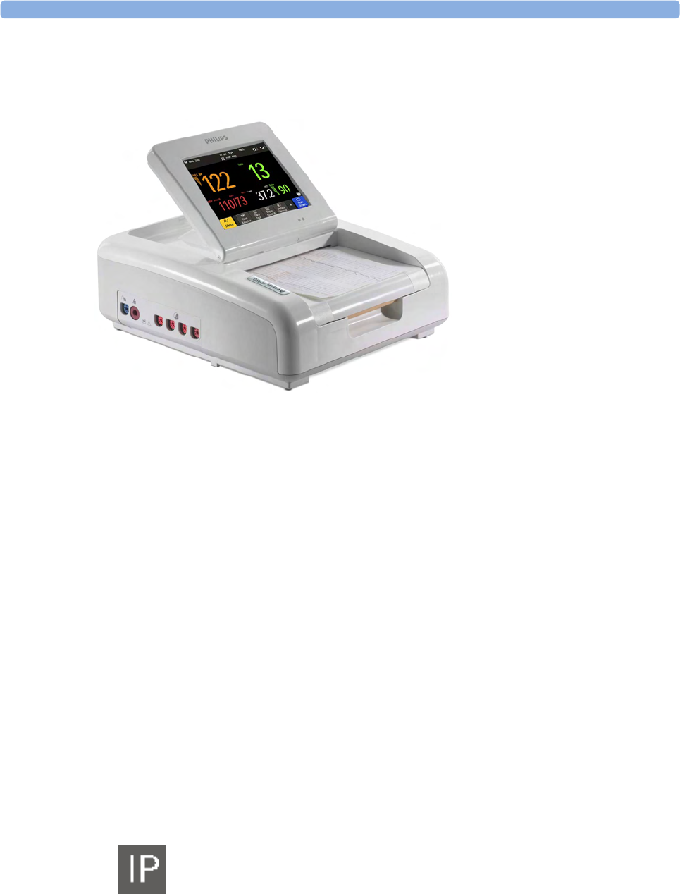
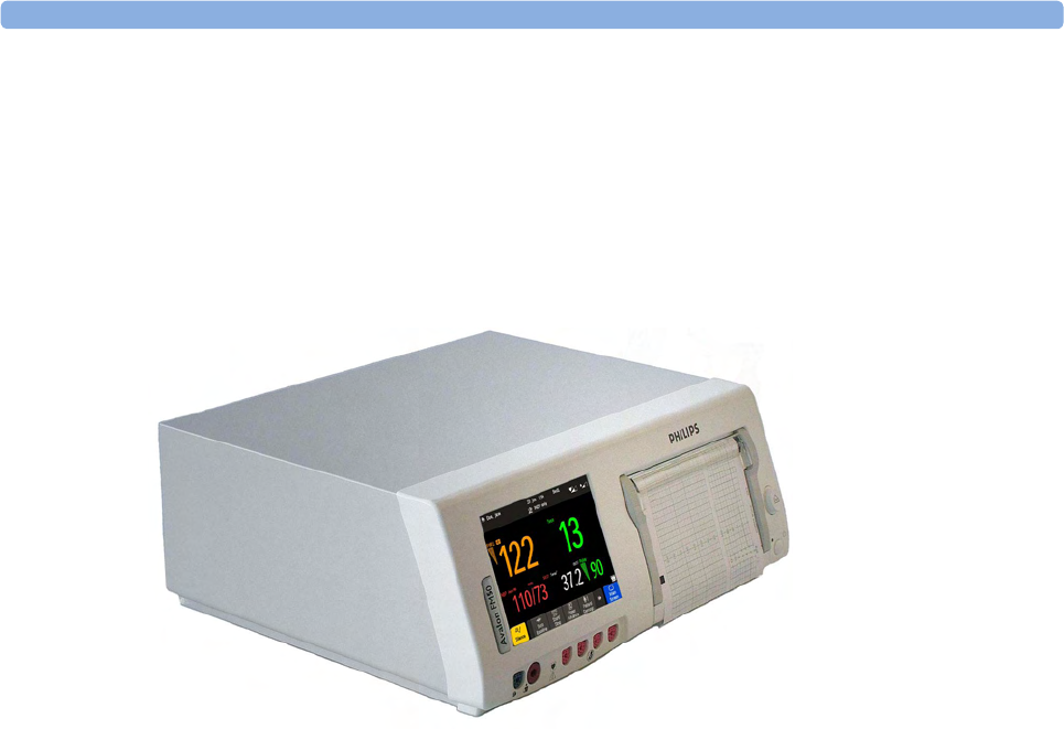
Avalon FM30
The Avalon FM30 fetal/maternal monitor offers a solution for both external and internal fetal
monitoring applications, and optional noninvasive maternal vital signs.
The Avalon FM30 shares all the features and capabilities of the Avalon FM20. In addition, you can
monitor one FHR internally with a direct fetal electrocardiogram (DECG), uterine activity internally
using an intrauterine pressure (IUP) catheter together with a Toco+ transducer or patient module.
The Avalon FM30 carries the IP label, indicating that it is capable of intrapartum monitoring.
3 Basic Operation
30
FM20/30 with
Battery
Option #E25
Only
The battery option for the FM20/30 provides support for the in-transport monitoring of all
measurements when disconnected from a power supply. Existing data storage is automatically
uploaded to OB TraceVue or IntelliSpace Perinatal after reconnecting it to the system. Trace printing
during transport is also possible.
Avalon FM40 and FM50
This section outlines the capabilities of your monitor.
Avalon FM40
The Avalon FM40 fetal/maternal monitor provides a solution for external fetal monitoring
applications, and noninvasive maternal vital signs.
You can monitor fetal heart rates (FHRs) externally using ultrasound, uterine activity using an external
Toco transducer, and the maternal heart rate (MHR) via maternal ECG electrodes, and noninvasive
blood pressure and maternal oxygen saturation (SpO2).
Measurements are displayed on a 6.5 inch color display as numerics. The display is a touchscreen, and
you operate the monitor using this touchscreen interface. The integrated recorder documents fetal and
maternal measurements as well as the user-defined annotations.
You can connect the monitor to an OB TraceVue/IntelliSpace Perinatal system with the RS232
connection, or over a LAN connection (with OB TraceVue Revision E.00.00 and later, or IntelliSpace
Perinatal Revision H.0 and later).
3 Basic Operation
31
Avalon FM50
The Avalon FM50 fetal/maternal monitor offers a solution for both external and internal fetal
monitoring applications, and noninvasive maternal vital signs.
The Avalon FM50 shares all the features and capabilities of the Avalon FM40. In addition, you can
monitor one FHR internally with a direct fetal electrocardiogram (DECG), and uterine activity
internally using an intrauterine pressure (IUP) catheter together with a Toco+ transducer or patient
module.
The Avalon FM50 carries the IP label, indicating that it is capable of intrapartum monitoring.
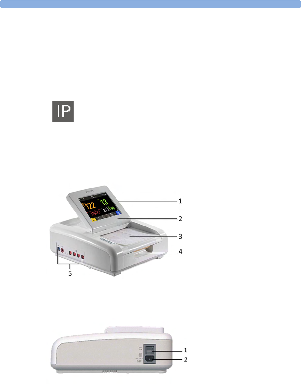
Getting to Know Your Avalon FM20/FM30
Overview
Right Side
1Touchscreen display (tilt and fold)
2Power LED
3Paper drawer
4Paper drawer release
5Connectors
1On/Off switch
2Power connector
3 Basic Operation
32
with Battery
Option
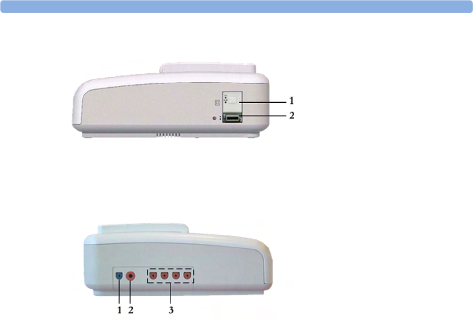
Left Side
Each of the fetal sensor sockets accepts any fetal transducer, one Avalon CL or one Avalon CTS
Cableless Fetal Transducer System base station, or an event marker.
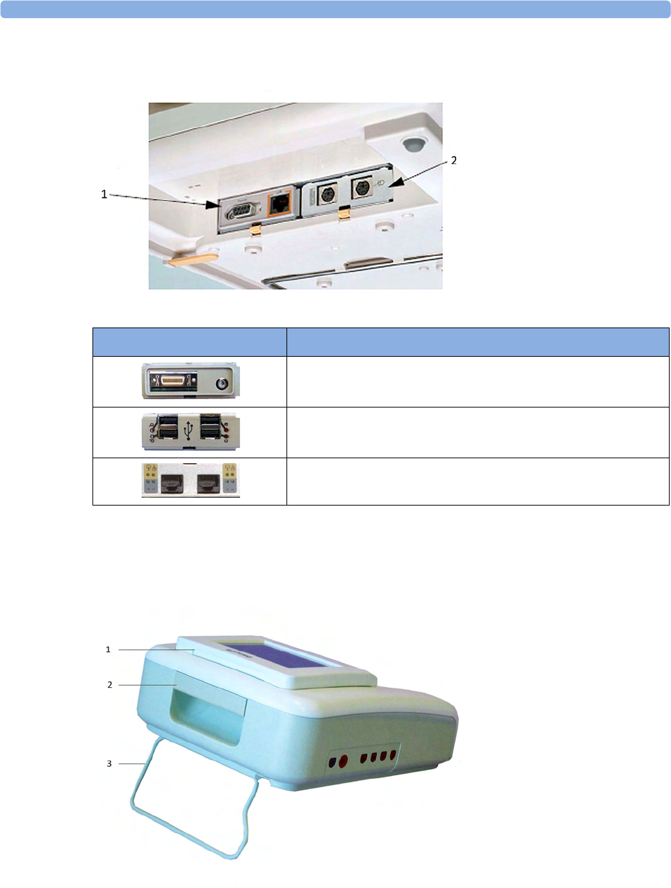
Bottom
There are five optional interfaces available for the Avalon FM20/30 monitor:
• LAN/RS232 system interface
• Dual PS/2 interface
• Dual MIB/RS232 interface
• Flexible Nurse Call interface
• USB ports interface
1On/Standby button with power LED
2MSL connector for external power
supply
1SpO2 socket (optional)
2Noninvasive Blood Pressure
socket (optional)
3Fetal sensor sockets
3 Basic Operation
33
You can use two of the five optional interfaces at the same time.
Rear
1LAN/RS232 system
interface
2Dual PS/2 system
interface
Optional Interfaces Description
Flexible nurse call interface card
Quad. USB ports
Dual MIB/RS232
1Display release
2Carrying handle
3Built-in stand
3 Basic Operation
34
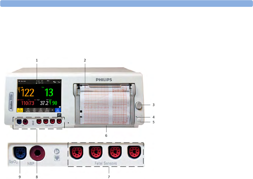
Getting to Know Your Avalon FM40/FM50
Front
Connect any fetal sensor or patient module at the fetal sensor sockets, including an Avalon CL or an
Avalon CTS via interface cable (with red connector).
1Touchscreen color display
2Transparent paper guide with tear-off
edge
3Paper eject button
4Power LED
5On/Standby button
6Recorder paper table
7Fetal sensor sockets
8Noninvasive blood pressure socket
(optional)
9SpO2 socket (optional)
3 Basic Operation
35
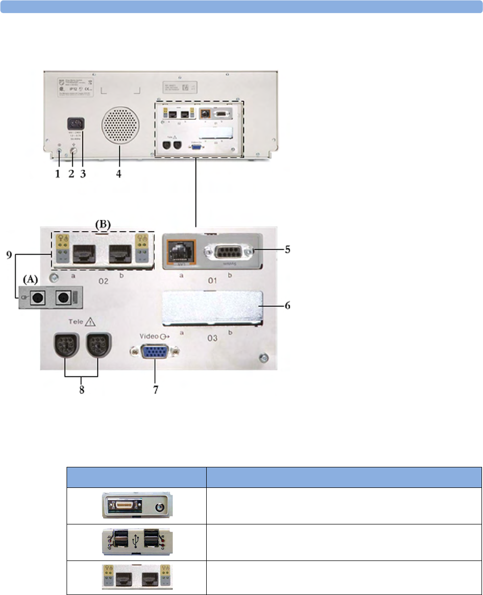
Rear
Two Avalon CL base stations, or one Avalon CTS can be also connected to the Telemetry interface
sockets using the interface cable (with black connector).
Additional Optional Interfaces
1Reserved for future use: protective
earth intended for use in system
installations
2Equipotential grounding point
3Power cord connector
4Loudspeaker
5Slot 01 for optional LAN/RS232
system interface (for connection to an
obstetrical information and
surveillance system)
6Slot 03 reserved for future use
7Video output (VGA)
8Telemetry interface
9Slot 02 for optional interfaces: Either
dual PS/2 system interface (A) for
mouse and keyboard connection) Or
MIB interface (B) for external
touchscreen connection, or the
optional interfaces for the flexible
nurse call or USB ports
Optional Interfaces Description
Flexible nurse call interface card
Quad. USB ports
Dual MIB/RS232 interface
3 Basic Operation
36
Connecting the Monitor to AC Mains
WARNING
• Always use the supplied power cord with the earthed mains plug to connect to an earthed AC
mains socket. Never adapt the mains plug from the fetal monitor to fit an unearthed AC mains
socket.
• Check that the line frequency is correctly configured in the Global Settings menu.
•FM20/FM30 only: The protective earth conductor is required for EMC purposes. It has no
protective function against electric shock. Double and/or reinforced insulation protects this
device against electric shock.
• Do not use AC mains extension cords or multiple portable socket-outlets.
Always ensure that the monitor is positioned so that the AC mains plug is easily accessible, to allow
disconnection of the monitor from the AC mains.
Wired Transducers
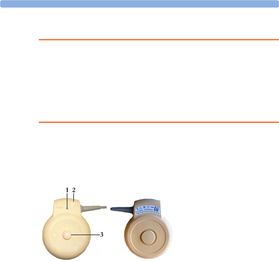
Toco (M2734A) and Toco MP Transducer (M2734B)
1Transducer finder LED - lights up
on the transducer supporting to
identify the measurement source
2"MP" for M2734B "Toco MP"
transducers (additionally capable
of providing the maternal pulse
measurement)
3Belt button
3 Basic Operation
37
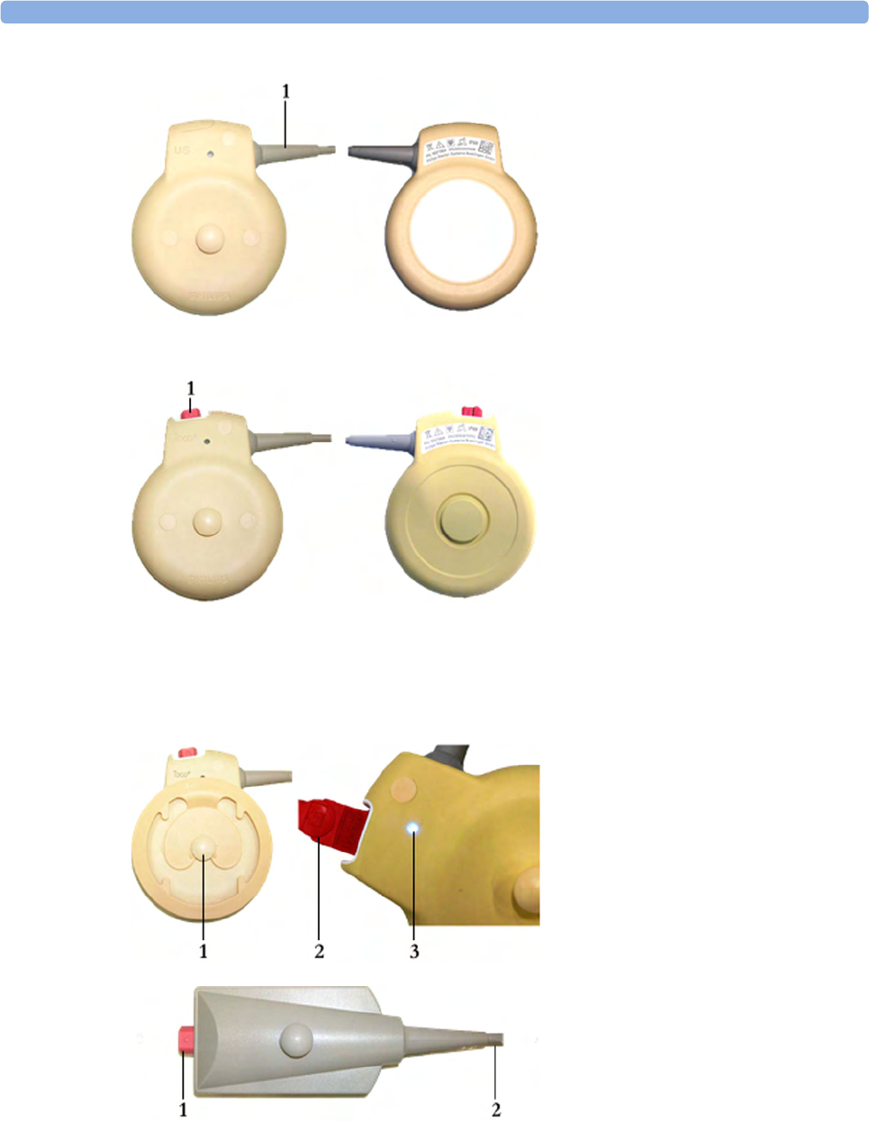
Ultrasound Transducer (M2736A)
1Cable - connects to any of the
four fetal sensor sockets on the
monitor
The M2736AA US transducer is
identical to the M2736A US
transducer, including all specifications
Toco+ Transducer with ECG/IUP capability
(M2735A)
1Connector - for connecting
ECG/IUP adapter cables
(M2735A Toco+ transducer only)
1Butterfly belt clip (shown fitted;
for use with belts without button
holes)
2Close-up of MECG adapter cable
connected to Toco+ transducer
3Close-up of active finder LED
Patient Module for ECG/IUP (M2738A)
1Connector - for connecting ECG/
IUP adapter cables (same as for
Toco+ transducer)
2Cable - connects to any of the four
fetal sensor sockets on the monitor
3 Basic Operation
38
Operating and Navigating
Your monitor has a touchscreen. Everything you need to operate the monitor, except the on and off
switch, is contained on its screen. Most screen elements are interactive. Screen elements include
measurement numerics, screen keys, information fields, status indicators, alarms fields, and menus.
Operator Position
The typical operator's position is in front of the monitor.
FM40/50 If an optional external touch display is connected to the monitor, you can operate the monitor using
the external touch display.
CAUTION
The screen contains sensitive personal data. For information how to protect personal information, see
“Protecting Personal Information” on page 17.
1Monitor
information line
2Measurement area
3Key area

3 Basic Operation
39
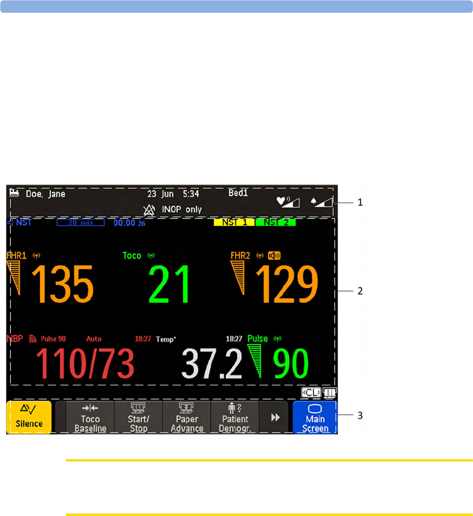
Screen Elements
Monitor Information Line
1LAN connection status indicator only. RS232 system connection is not indicated. The
locomotive icon indicates if the fetal monitor is connected to OB TraceVue/IntelliSpace
Perinatal, via a LAN cable or not.
2Patient identification
3Date and time
4Bed label (when connected to a Philips OB TraceVue/IntelliSpace Perinatal system)
5Fetal heart sound volume adjust/indicator
6Alarm volume adjust/indicator
7INOP and alarm status area - shows active alarm messages
3 Basic Operation
40
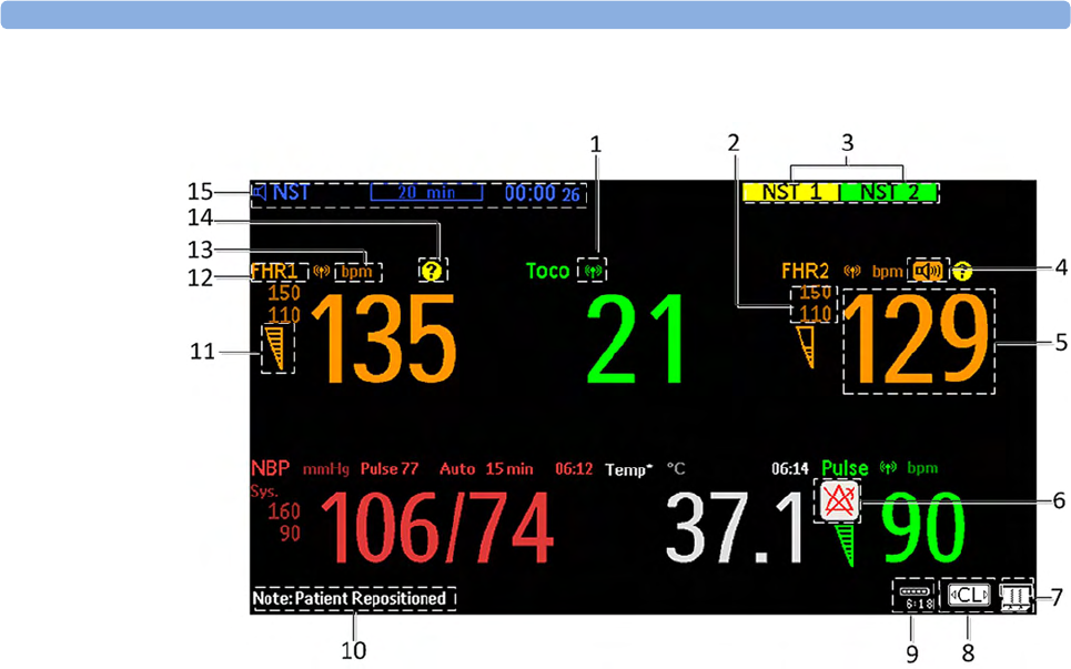
Measurement Area
1Antenna symbol (indicates a cableless measurement from a connected Avalon CL or Avalon CTS
system)
2Configurable alarm limits
3NST test
4Audio source symbol
5Measurement numeric
6Alarms off symbol
7Fetal trace recorder - status indicator
8Avalon CL or Avalon CTS system - status indicator
9Battery status indicator
10 Status line - shows status and prompt messages
11 Signal quality indicator: good, acceptable, poor
12 Fetal heart rate measurement label
13 Measurement unit (configurable)
14 Coincidence symbol (see “Cross-Channel Verification (CCV)” on page 159)
15 NST timer, if configured (default is Off)
3 Basic Operation
41
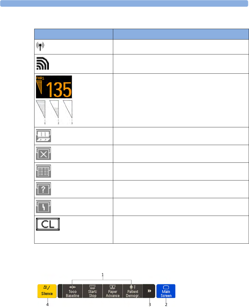
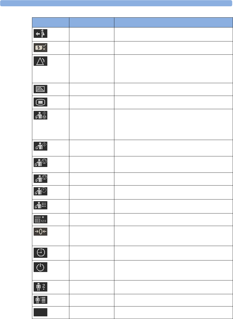
Screen Details
Key Area
Icon Description
The antenna symbol indicates a cableless measurement
(Avalon CL or Avalon CTS).
Indicates a short range radio measurement (CL Pods).
Signal quality indicator:
1Good
2Acceptable
3Poor
Fetal trace recorder - status indicator
Fetal recorder is on
Fetal recorder is off (when Paper Save Mode is off)
Fetal recorder is off (when Paper Save Mode is on)
There is a user-solvable recorder error (paper out, paper jam,
wrong paper scale set)
Fetal recorder is defective: call service
When an Avalon CL or Avalon CTS system is connected to the
monitor, a CL symbol is shown. It changes with the states of the
connected cableless device see “Cableless Status Indication” on
page 95.
1SmartKeys - these can vary according to your monitor's configuration
2Main Screen - closes all open menus and windows and returns to main screen
3Scroll to display more SmartKeys
4Silence - acknowledges all active alarms by switching off audible alarm indicators
3 Basic Operation
42
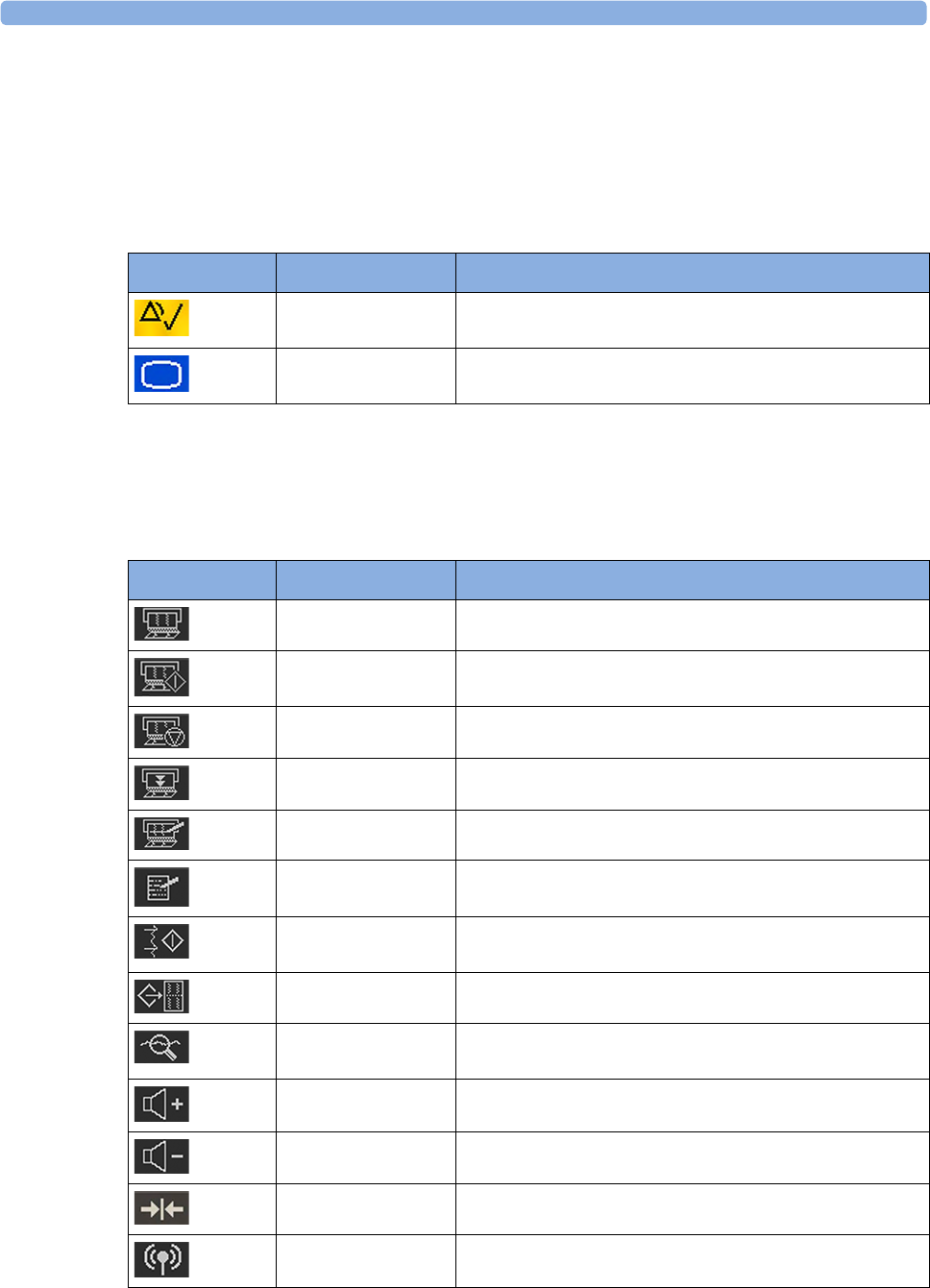
Keys
The monitor has three different types of keys.
Permanent Keys
A permanent key is a graphical key that remains permanently on the screen, giving you fast access to
functions.
SmartKeys
SmartKeys are configurable graphical keys, located at the bottom of the main screen. They give you
fast access to functions. The selection of SmartKeys available on your monitor depends on your
monitor configuration, and on the options purchased.
Key Name Function
Silence Acknowledges all active alarms by switching off audible
alarm indicators.
Main Screen Closes all open menus and windows and returns to the
main screen.
SmartKey Name Function
FRStart/Stop Turns the trace recorder on or off
Start Rec Turns the trace recorder on
Stop Rec Turns the trace recorder off
Paper Advance Advances the paper automatically to the next fold
Set Marker Marks an event
Enter Notes Enters notes
Record ECG Starts printing the MECG, DECG, or both waves, when
both are available
Stored Rec Prints trace data from the monitor's memory
NST Report Initiates an NST trace interpretation and obtains a Non-
stress test (NST) report
Sound Vol. Up Increases the fetal heart rate volume
Sound Vol. Down Decreases the fetal heart rate volume
Toco/IUP Bsl Resets Toco baseline
Tele Info Calls up the Tele Info window
3 Basic Operation
43
Call Patient Pages the patient. Only enabled if at least one
CL transducer is currently active
cl F&M Status Calls up the cl F&M Electrode Status window
Pause Alarms Pauses alarm indicators. Pause duration depends on
monitor configuration. If the pause duration is infinite, this
key is labeled Alarms Off
Select again to immediately re-enable alarm indicators
Defaults Loads User Default
Main Setup Enters main setup menu
Strt/Stp NBP Starts/stops manual noninvasive blood pressure
measurement
Starts auto series
Stops current automatic measurement within series
Start NBP Starts manual noninvasive blood pressure measurement
Starts auto series
Stop NBP Stops manual noninvasive blood pressure measurement
Stops current automatic measurement within series
Stop All NBP Stops all noninvasive blood pressure measurements
Repeat NBP Sets the time interval between two noninvasive blood
pressure measurements
NBP Modes Access NBP mode selection and setup, with direct start/
stop function
Enter Temp Allows the manual input of the patient's temperature
Zero IUP Resets the display and trace to 0. If you do not zero the IUP
measurement properly, the pressure trace may exceed the
paper scaling.
Timer Enters NST timer window
Standby Switches to standby screen, suspends monitoring. All
numerics and waves disappear from the display. All settings
and patient data information are retained
Patient Demogr. Enters the patient identification menu to admit/discharge
QuickAdmit Quick admits the patient for monitoring
Blank Key Blank key, can be used as divider between a group of keys
SmartKey Name Function

3 Basic Operation
44
Pop-Up Keys
Pop-up keys are context-sensitive graphical keys that appear automatically on the monitor screen when
required. For example, the Confirm pop-up key appears when you need to confirm a change.
Using the Touchscreen
Select screen elements by pressing them directly on the monitor's screen.
Disabling Touchscreen Operation
1To temporarily disable the touchscreen operation of the monitor, press and hold the Main Screen
permanent key for about three seconds. A red padlock will blink on the Main Screen permanent
key.
2Press and hold the Main Screen permanent key again for about three seconds to re-enable the
touchscreen operation.
Operating Modes
When you switch on the monitor, it starts up in Monitoring Mode. To change to a different mode:
1Select the Main Setup menu.
2Select Operating Modes and select a mode.
Your monitor has four operating modes. Some are passcode protected.
Mode Description Password
Protected
Monitoring Mode The Monitoring Mode is the normal operating mode to
monitor patients. You can change elements such as alarm
limits. When you discharge the patient, these elements
return to their default values.
You cannot select or change grayed out items. These items
are for your information only. To change these items,
switch to the Configuration Mode.
no
Demo Mode The Demo Mode is used for demonstration and training
purposes. Do not change into Demo Mode during
monitoring. When transducers are connected to the
monitor and the recorder is on, a demo trace is recorded.
But the demo trace is not transmitted when the fetal
monitor is connected via RS232 to an information and
surveillance system such as OB TraceVue/IntelliSpace
Perinatal.
yes

3 Basic Operation
45
A field displayed at the fetal monitor screen indicates if the monitor is in Demonstration Mode,
Configuration Mode, or Service Mode. To change to a different mode, select this field.
Automatic Screen Layouts
Your monitor's preconfigured screen layouts define how measurement information is arranged on the
screen. The monitor automatically applies the correct screen layout for the measurements you are
monitoring. No user action is required.
Connecting or disconnecting transducers, or activating or deactivating a cableless measurement, results
in an automatic adjustment of the screen layout. When a measurement is off, its numerics are removed
from the monitor's screen. The monitor stops acquiring data and generating alarms for this
measurement. If you disconnect a transducer while it is performing a measurement, the monitor issues
a disconnect INOP (and in the case of SpO2, replaces the measurement numeric with a question
mark).
Settings
This section describes the various settings available on the monitor.
Active Settings
What the monitor displays, and the way it operates, is controlled by its settings. They determine sound
volume settings, recorder settings, high and low alarm limits and so forth.
The "active settings" are the current settings the monitor uses, including any adjustments made by the
last user. Active settings are not permanent, but are retained after a loss of mains power.
There are also two preconfigured default settings:
•User Default
•Factory Default
Configuration Mode The Configuration Mode is for personnel trained in
configuration tasks. You can change and store the default
values and patient profiles permanently in the
Configuration Mode. These tasks are described in the
Configuration Guide. During installation, the fetal
monitor is configured for use in your environment. This
configuration defines the default settings you work with
when you switch on the fetal monitor.
yes
Service Mode The Service Mode is for trained and authorized service
personnel only.
yes
Mode Description Password
Protected

3 Basic Operation
46
User Default
The User Defaults are a complete configuration stored in the monitor's long-term memory. You can
store the active settings, modified to your preference, in the User Defaults (in Configuration Mode).
In Monitoring Mode, you can load the User Defaults settings to return to your preferred settings:
1Select the Defaults SmartKey.
2Select Confirm in the dialog box to load the User Defaults.
Factory Default
The Factory Defaults is a complete configuration predefined at the factory. You cannot modify it. In
Configuration Mode, you can load the Factory Defaults as the active settings.
CAUTION
This resets all settings to factory defined values, but be aware that some values will differ from those
with which the fetal monitor was originally shipped from the factory (recorder speed and paper scale
type will need to be corrected, for instance). After loading the Factory Defaults, check the settings, and
if necessary, change them to the settings you normally use.
You can use the Factory Defaults as the basis for producing your User Defaults. See the Configuration
Guide for details.
Global Settings
General monitor configuration settings are stored in the Global Settings. These include settings for line
frequency, QRS type, and whether the monitor is automatically reset to the User Defaults after a power
interruption of more than one minute. You can change the Global Settings in Configuration Mode.
Changing Measurement Settings
Each measurement has a setup menu in which you can adjust all of its settings. You can enter a setup
menu:
1with the measurement numeric - select the measurement numeric on the screen to enter its setup
menu. For example, to enter the Setup FHR1 menu, select the FHR1 (fetal heart rate 1) numeric.
2with the Main Setup SmartKey - if you want to set up a measurement when the measurement is
switched off, use the Main Setup SmartKey and select Measurements. Then select the measurement
name from the pop-up list. With this SmartKey you can access any setup menu in the monitor.
This guide always describes the entry method using the measurement's setup menu. You can use the
method you prefer.

3 Basic Operation
47
Changing Monitor Settings
To change monitor settings such as brightness, or touch tone volume:
1Enter the Main Setup menu.
2Select the setting you want to change, or select User Interface to enter a sub menu where you can
change user interface settings.
Adjusting the Screen Brightness
1Enter the Main Setup menu.
2Select User Interface.
3Select Brightness.
4Select the appropriate setting for the screen brightness. 10 is the brightest, 1 is the least bright.
Optimum is suitable for most situations.
Adjusting Audio Volume
Here you can adjust the audio volume for Alarm Volume, QRS Volume, and Timer Volume. To adjust an
audio volume:
1Enter the Main Setup menu.
2Select User Interface.
3Select Audio Volumes, then select one of the volume types, and select an audio level. 10 is the
loudest and 1 is the quietest. Selecting zero switches the volume off.
Setting the Date and Time
The current date and time is displayed in its own element in the information line of the monitor screen.
1Select the date and time screen element from the monitor's information line to enter the Date,
Time menu.
2Select, in turn, the Year, Month, Day, Hour (in 24 hour format), and Minute, as necessary.
3Select Store Date, Time to change the date and time.
WARNING
Do not change the date and time setting, if the fetal monitor is connected to a Philips OB TraceVue/
IntelliSpace Perinatal system. The monitor uses the OB TraceVue/IntelliSpace Perinatal system date
and time, including daylight saving time changes. As long as the fetal monitor is connected to the OB
TraceVue/IntelliSpace Perinatal system via the LAN-setup (locomotive symbol displayed on the
monitor's screen), the option to change the date and time settings at the fetal monitor are disabled, this
is not valid for RS232 connections, or the connection to other systems.

3 Basic Operation
48
When disconnected from AC power, the monitor retains the date and time setting for at least two
months. If the monitor is off longer than two months, and the operating system detects that the date
and time settings are invalid, the monitor initiates a "cold" start and sets the date to 1 Jan 1997 and the
time to 00:00.
Checking Your Monitor Revision
1Select Main Setup, Revisions to open the Monitor Revision menu.
2From the Monitor Revision menu, select the monitor component for which you need revision
information.
Preparing to Monitor
Confirm fetal life before you begin fetal monitoring. Familiarize yourself with the basic operation
principles before you start to monitor.
CAUTION
Check the fetal monitors housing for damage before you start to monitor as part of your safety
precautions.
After you switch on the monitor:
1Check that you have the correct patient cables and transducers plugged in for the measurement
you want to monitor.
2If you use an Avalon CL or Avalon CTS system, check if the cableless transducers are ready and
charged (apparent by either a lit up green or yellow LED indicator).
3Admit your patient to the monitor (see “Admitting a Patient” on page 147).
4Check that the alarm limits, alarm and fetal heart rate volumes, patient category, and so forth, are
appropriate for your patient. Change the settings if necessary.
5Refer to the appropriate measurement section for details of how to perform the measurements
you require.
6Start recording.
There is no special emergency access for the Avalon Fetal monitors. For all clinical use cases according
the Intended Use, the monitors are taken into operation by connecting them to AC mains and by
switching them on.
Switching On: FM20/FM30
1Connect the monitor to AC mains and switch the monitor on.
– The green power-on LED lights up.
– The monitor performs a self-test as it starts up. Selftest: OK, the serial number, and revisions
for the software and firmware are printed on the fetal trace paper (if recorder Auto Start is
configured to On).
– The monitor display comes on.
– There is a start-up tone from the loudspeaker.
Battery
Option • If this option has been chosen, the green power-on LED on both the external power supply and
the battery LED indicator will light up.

3 Basic Operation
49
Switching On: FM40/FM50
1Connect the monitor to AC mains.
– The green LED lights up.
2Press the On/Standby switch.
– The monitor performs a self-test as it starts up. Selftest: OK, the serial number, and revisions
for the software and firmware are printed on the fetal trace paper (if recorder Auto Start is
configured to On).
– The monitor display comes on.
– There is a start-up tone from the loudspeaker.
Adjusting the Display Angle (FM20/FM30)
You can tilt the display on the FM20 and FM30 to one of five different positions, or you can fold it
completely down. The tilt/fold mechanism works on a one-way ratchet system. You hear a click as
each of the five positions is reached. The screen can be folded back down only after tilting the display
forwards as far as it will go.
To tilt the display from the folded position:
1Unlock the display by releasing the catch.
2Lift the display forward. You will hear a click as the first position engages. If you want to tilt the
display further, lift the display further forward until you reach the desired angle.

3 Basic Operation
50
3To fold the display, pull the display forwards as far as it will go.
4Then push the display all the way back until it clicks shut.
If your monitor is wall-mounted, the display should be folded flat.
Fastening Belts and Transducers
You can use more than one belt if, for example, you are monitoring uterine activity and FHR
simultaneously. There are two basic ways to fasten belts and transducers:
• Belts with button fixings.
• Velcro belts together with the butterfly belt clip.
What You Need
• Ultrasound transducer
• Toco MP or CL Toco+ MP transducer
•Ultrasound gel
• Transducer belt (and optional butterfly belt clip, if applicable)

3 Basic Operation
51
Using Belts with Button Fixings
1Place the transducer belt across the bed, so that the fixing button will face away from the mother
when it is fastened.
2Lie the patient on the bed and arrange the belt around her until it is tight but still comfortable.
3Fasten the belt by pushing the fixing button through the overlapping section of the belt. Ensure
that the fixing button and the loose ends of the belt are at the patient's side.
4When you have positioned a transducer satisfactorily, you can attach it to the belt by pushing the
belt button on the transducer through one of the holes in the belt.
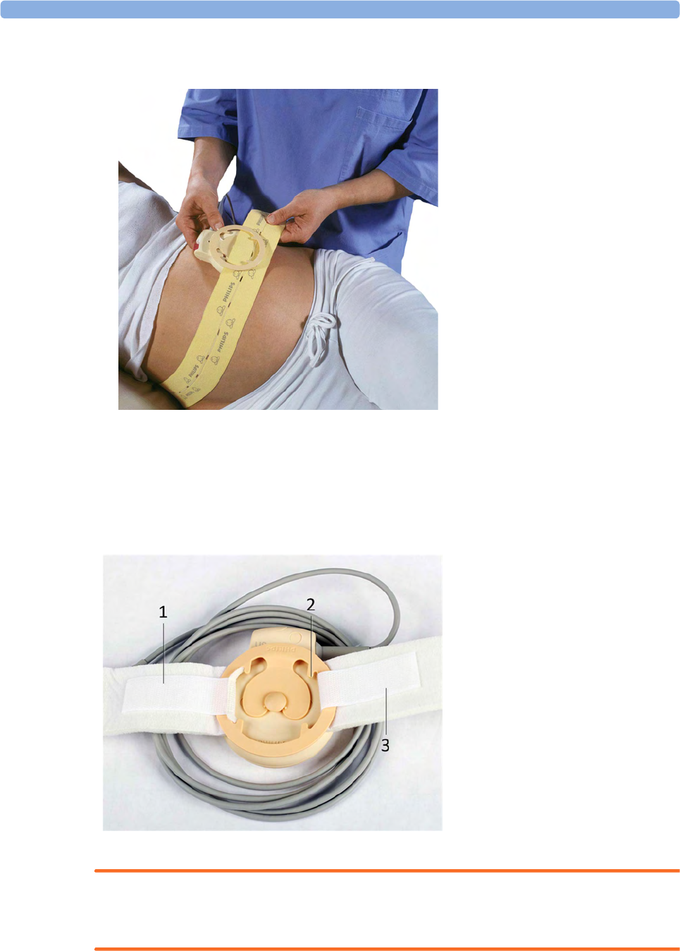
3 Basic Operation
52
5Alternatively, attach the butterfly belt clip to the transducer belt button and use this to attach the
transducer to the belt. The clip allows you to slide the transducer for easy repositioning.
Using Belt with Velcro Fixings
Insert one end of the belt between the belt guides on one side of the butterfly belt clip, and secure with
the velcro fixing. Insert the other end of the belt between the belt guides on the other side of the
butterfly belt clip, adjust for the correct tension, then secure with the velcro fixing.
WARNING
When connecting devices for acquiring measurements, always position cables and NBP tubing
carefully to avoid entanglement or potential strangulation.
1Velcro fixing
2Belt guides
3Velcro fixing
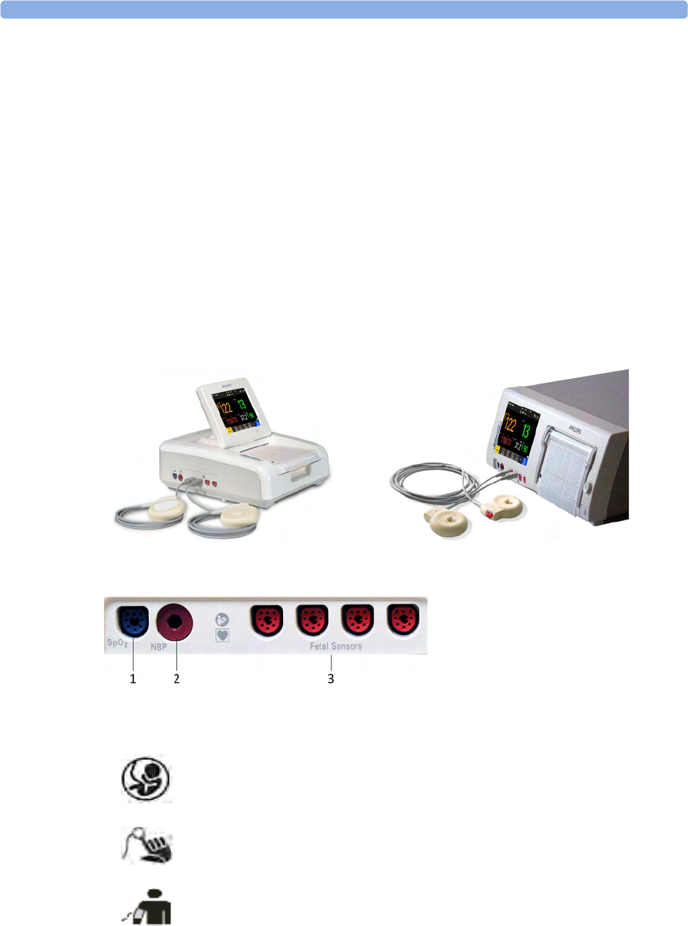
3 Basic Operation
53
Repositioning Transducers
A patient possibly wears transducers for long periods without interruption. In rare cases, skin
irritations may occur if a transducer is attached to one location for a longer period. To ensure there are
no adverse effects on the patient's skin, inspect the transducer application site at least every three
hours. If the skin quality changes, move the transducer to another site.
The ultrasound transducer is often repositioned to follow the fetal heart as part of the normal
monitoring process, but this is not so for the Toco transducer. Therefore, remember to check its
application site (between contractions) at least every three hours.
To reduce the risk of skin irritations, do not allow a cleaning or disinfecting agent to remain on the
transducer. Follow all instructions that accompany the specific cleaning and disinfecting agents you are
using. Remove agent residues with a cloth dampened in water before applying a transducer to a patient.
See “Care and Cleaning” on page 261 for further information, and a list of approved agents.
Connecting a Transducer to the Monitor
1SpO2 socket
2Noninvasive blood pressure socket
3Fetal sensor sockets
You can plug a fetal transducer, an ECG/IUP patient module, an Avalon CL or
Avalon CTS Cableless Fetal Transducer System interface cable (red connector), or
an external event marker into any of the four fetal sensor sockets marked by the
fetal symbol, or "Fetal Sensors" (depending on geography).
For measuring maternal SpO2, connect the sensor to the socket marked with the
SpO2 symbol or "SpO2" (depending on geography).
For maternal noninvasive blood pressure, connect the cuff to the socket marked
with the NBP symbol or "NBP" (depending on geography).

3 Basic Operation
54
For the FM20 and FM30, you can connect an Avalon CL or Avalon CTS Cableless Fetal Transducer
system interface cable (red connector) to one of the fetal sensor sockets at the left side of the monitor.
For the FM40 and FM50, you can connect an Avalon CL or Avalon CTS Cableless Fetal Transducer
System interface cable (black connector) to one of the two dedicated black sockets marked "Tele" at
the rear of the monitor, as an alternative to using one of the fetal sensor sockets (red connector) at the
front.
What You See on the Monitor
When you connect a transducer or sensor, the measurement numeric appears on the screen.
Fetal heart rate measurements are labeled in the order in which you plug in the transducers for those
measurements. It does not matter which fetal sensor socket you use, as the monitor allocates a channel
automatically. For instance, when monitoring triplets, the first transducer you connect is automatically
allocated a channel, and the measurement is labeled FHR1, the second FHR2, and the third FHR3. See
also chapters “Monitoring Twin FHRs” on page 183 and “Monitoring Triple FHRs” on page 191.
When you touch a measurement numeric on the screen, the setup menu for that measurement opens.
The fetal sensor socket to which the transducer for this measurement is connected is identified by the
transducer position indicator in the setup menu header.
1Interface cable to Avalon CL and
Avalon CTS Cableless Fetal
Transducer System.
2Connect the black connector to one
of the two black sockets (marked
"Tele") on the rear of the monitor.
FM20/FM30 FM40/FM50
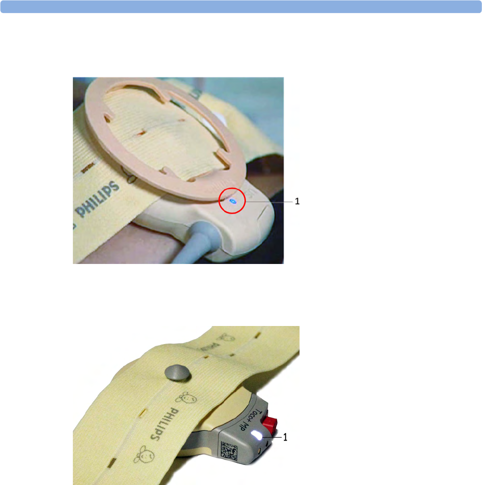
3 Basic Operation
55
The blue finder LED on a wired fetal transducer lights up when you touch the measurement on the
screen, allowing you to identify the corresponding transducer.
The white finder LED on a cableless fetal transducer lights up when you touch the measurement on
the screen, allowing you to identify the corresponding transducer.
The recorder prints an annotation showing the date, time, recorder speed, and Monitoring Mode. It
repeats this every 10 minutes.
Start Recording
Checking/Setting Paper Scale
You can check the paper Scale Type (US for USA, or Internat'l for other geographies) in the Fetal
Recorder menu. In Monitoring Mode, you can see these settings (grayed out), but you cannot change
them. They can be changed in Configuration Mode, see the Configuration Guide.
NOTE
Check if the scale type of the paper and the settings in the fetal monitor match.
1finder LED
1finder LED cableless transducer

3 Basic Operation
56
Paper Guide FM40/FM50
The recorder in the FM40 and FM50 features a transparent paper guide which:
• facilitates correct alignment of the paper, both during loading and while the recorder is running.
See “Loading Paper FM40/FM50” on page 65.
• incorporates a tear-off edge, which not only allows you to tear off the trace paper where you like
(not necessarily at a fold), but also helps to avoid paper misalignment while doing so (see “Tearing
Off the Paper” on page 61).
• is removable (see “Removing the Paper Guide: FM40/FM50” on page 269).
Switching the Recorder On and Off
In addition to the normal recording of real-time traces, you will sometimes see a trace recovery
printout from the monitor's internal backup memory at high speed when the recorder is started. For
details, see “Recovering Traces on Paper” on page 257.
For an explanation of the various symbols that can appear on the trace recording, see “Recorder
Specifications” on page 308.
To switch the recorder on, select in Main Setup the menu item Fetal Recorder, or press one of the
SmartKeys: Start/ Stop or Start Recordng.
The "recorder on" status indicator is displayed in the bottom right-hand corner of the screen when you
switch on the recorder.
The paper advances quickly for 2 cm and then returns to the set speed. Whenever the recorder is
switched on, a trace header is printed vertically on the trace paper, containing the following:
•Selftest: OK: confirmation that the monitor's self-test completed successfully, and that it is ready to
use
• the software revision and firmware revision
•the serial number
•the time
•the date
• patient name and medical record number (if entered)
• the recorder speed
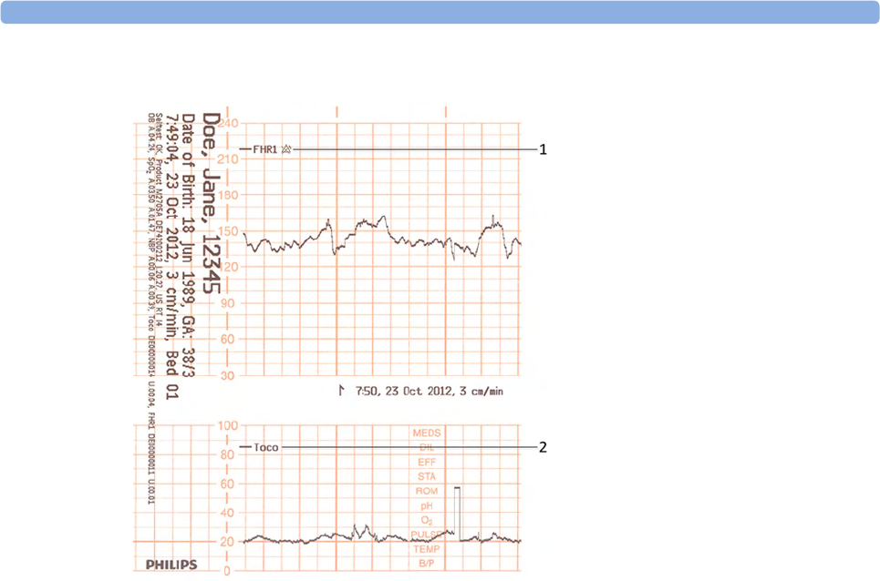
3 Basic Operation
57
The current monitoring modes (if any transducers are connected to the monitor) are printed.
Whenever a transducer's mode is changed, the following are printed:
•the time
•the date
• trace identification symbols
• the recorder speed
The monitor prints the time, date, recorder speed, and monitoring modes in the trace header when
first switched on, in a periodic time stamp every ten minutes after, and if the monitoring modes
change. The time stamp begins with the symbol shown below. The data is reprinted in the header if the
time and date are locally adjusted, or if an obstetrical information and surveillance system is connected
that readjusts the time and date automatically.
1Fetal heart rate label
2Uterine activity label
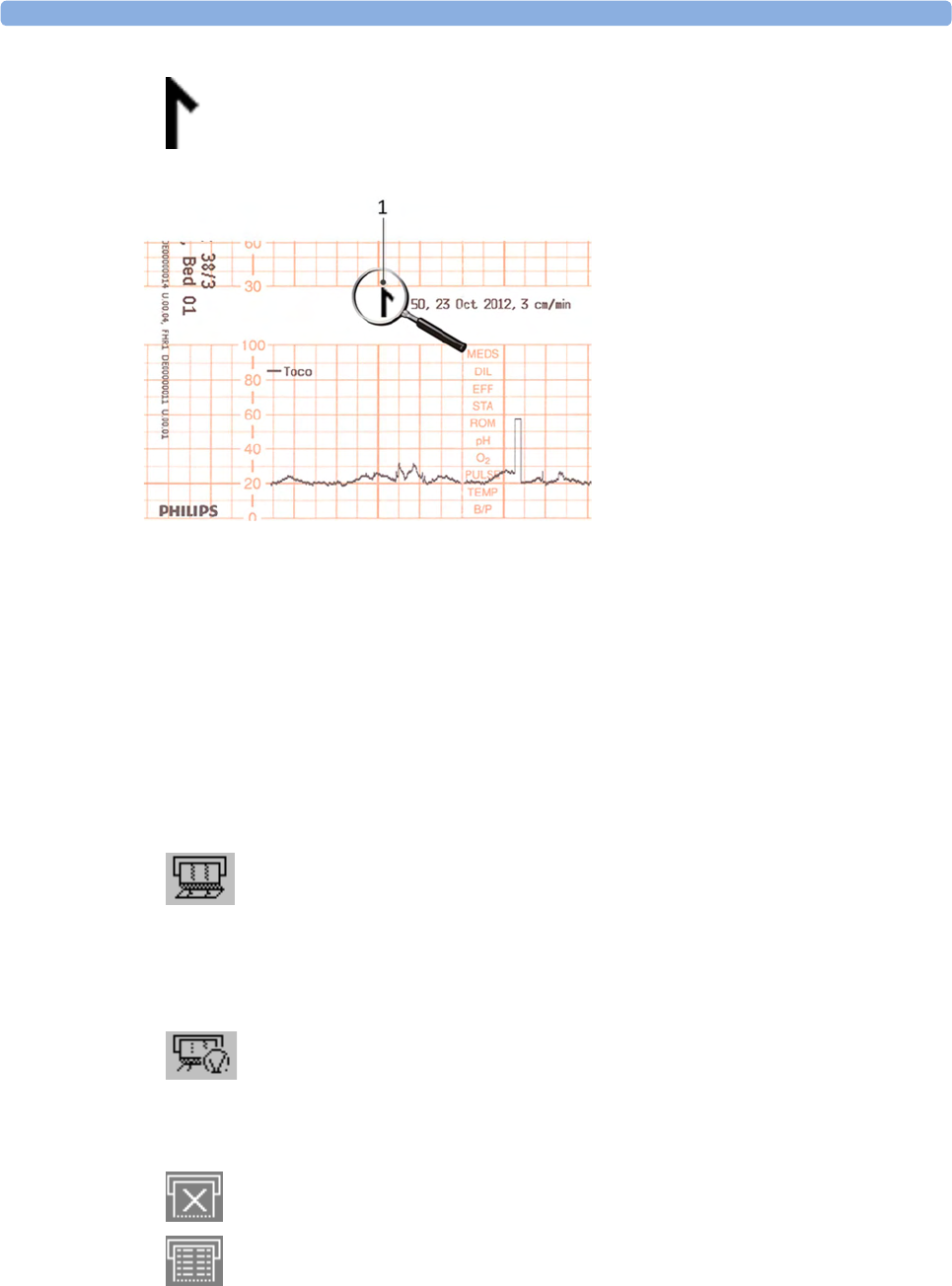
3 Basic Operation
58
The trace records maternal parameters also. When measuring noninvasive blood pressure, the
annotation is made at the end of the measurement. If the noninvasive blood pressure measurement
repetition time is short, the noninvasive blood pressure numeric may not always be printed.
The recording of notes (see “Entering Notes” on page 69) or time/date information may be
interrupted by connecting, or unplugging a transducer, or by a change in measurement-related setting
(for example, artifact suppression, Toco sensitivity, or alarm settings).
A new patient admission or a change to the paper scale setting stops all annotations, and prompts a
new vertical trace header to be printed.
To switch off the recorder:
1Either select Start/Stop from the Fetal Recorder menu.
2Or press one of the SmartKeys (depending on configuration): fetal recorder Start/ Stop or Stop
Recordng.
If your recorder is configured with Confirmed Stop on (a Configuration Mode setting), you will
need to confirm that you want to stop the recorder, before it will stop.
When the recorder is off, the "recorder off" status indicator is displayed in the bottom right-hand
corner of the screen: When the Paper Save Mode is set to Off the paper symbol shows an x mark,
and when Paper Save Mode is On the icon shows a paper trace icon.
1Time stamp printed every ten
minutes
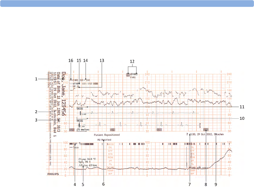
3 Basic Operation
59
Recording Elements
A variety of information can appear on the recorder trace. Here is a sample trace with some of the
most common elements and their meaning. Each trace header contains the last name and first name,
the patient ID, patient date of birth, the current date and time, patient's bed label, and the gestational
age of the pregnancy.
1Name, patient ID, date of birth, current date and time
2Recorder speed
3Gestational age and patient bed label
4FMP - Fetal Movement Profile
5Other measurements for the patient such as temperature, arterial oxygen saturation, and pulse
6Entered notes such as patient repositioned, or MD notified, or others
7Time stamp
8Trace separation
9Recorder speed
10 Maternal ECG
11 Direct ECG
12 Coincidence of heart rate detected
13 HR with Alarms Off symbol
14 Alarm Limits
15 dFHR2 (second fetal heart rate from DECG)
16 FHR1 (first fetal heart rate)

3 Basic Operation
60
Caution
The trace contains sensitive personal data. For information how to protect personal information, see
“Protecting Personal Information” on page 17.
Choosing Recorder Speed
You can choose a recorder speed of 1, 2, or 3 centimeters per minute (cm/min). The default setting is
3 cm/min.
The ACOG technical bulletin on FHR monitoring states that "accurate pattern recognition is difficult if not
impossible at 1 cm/min and that 1 cm/min is only recommended for more economic screening. When FHR
abnormalities arise, the faster recorder speeds will enhance FHR pattern recognition".
Additionally, because a change in recorder speed results in a change in the appearance of an FHR trace,
you are advised to ensure ALL monitors in your institution are set to the same speed.
To set the recorder speed (in Configuration Mode), see the Configuration Guide.
Advancing the Paper
You can advance the paper automatically to the next fold by pressing the Paper Advance SmartKey at
any time except during a stored data recording. This is also possible using the Fetal Recorder menu.
Marking an Event
You can record significant events on the trace paper (for example, when pain medication is
administered or when the mother changes position). The mother can use the remote event marker to
mark events herself. You connect the remote event marker to any free fetal sensor socket.
To mark an event on the trace paper, you can:
1Either select the Set Marker SmartKey.
2Or press the button on the optional remote event marker (989803143411). The remote event
marker is connected to the monitor via any fetal transducer socket.

3 Basic Operation
61
A small arrow is printed on the heart rate scale on the trace paper.
This reflects exactly when the marker button was first pressed; keeping the button pressed has no
influence on the annotation.
Tearing Off the Paper
CAUTION
Never pull on the paper to advance it, as this can cause misalignment of the paper. Always tear off the
paper along the perforation.
FM40/FM50 The recorder's paper guide incorporates a tear-off edge, allowing you to tear off the trace paper cleanly
where you like (not necessarily at a fold). When you are not using the paper guide, always tear off the
paper along the perforation.
To tear off the trace paper after monitoring using the paper guide:
1If the recorder is running (the "recorder on" status indicator is displayed), turn off the recorder by
selecting the fetal recorder Start/ Stop SmartKey or the Stop Recordng SmartKey.
2Tear off the paper as shown in the picture. To ensure a clean tear, always tear in an upwards
motion, as indicated by the arrows. You can start tearing from the left or right (right-handed user

3 Basic Operation
62
shown). You may want to use both hands to guarantee that the paper is not misaligned during the
tear off.
3If you wish to tear off the paper at a fold, select the Paper Advance SmartKey, wait for the paper to
stop, then tear it off.
FM20/FM30 The FM20/FM30 does not have a paper guide. The procedure is the same as described for the FM40/
FM50 with the exception that you should advance the paper to a perforation.
If you wish to tear off the paper at a perforation, select the Paper Advance SmartKey, wait for the paper
to stop, then tear it off.
Paper-Out Indication
Each pack of paper has 150 pages. The monitor issues a paper-out warning in the status line at the
bottom of the screen, when there are five pages to go. If you switch on the recorder or press the Paper
Advance key when there are fewer than five pages remaining, it may take two pages before the alarm is
activated. Load a new pack in time.
If the recorder runs out of paper, an audible paper-out alarm is sounded, if so configured. See
“Loading Paper FM40/FM50” on page 65, and “Loading Paper FM20/FM30” on page 62 to learn
how to reload paper.
Fetal traces continue to be recorded into the monitor's backup memory, and can be retrieved and
printed completely if new paper is loaded within one hour, when the Bridge Paperout setting is enabled
in Configuration Mode. See “Recovering Traces on Paper” on page 257 for further information.
Loading Paper FM20/FM30
CAUTION
Using recorder paper that is not approved by Philips can result in accelerated paper fading and can
damage the thermal line printhead. This type of damage is not covered by warranty.
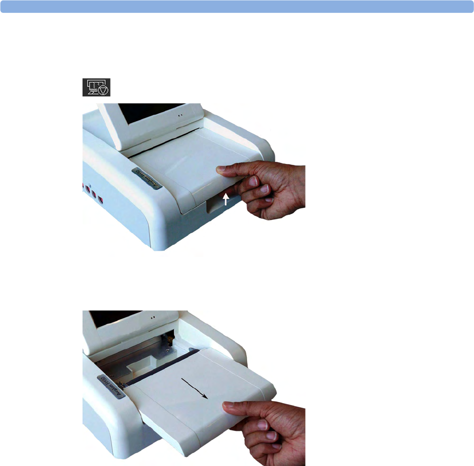
3 Basic Operation
63
FM20/FM30 To load a pack of paper:
1If the recorder is on, press the recorder Start/ Stop SmartKey or the Stop Recordng SmartKey to
turn it off before loading a new pack of paper.
2Press the paper table release to unlock the paper drawer and then pull the table forward to open it
fully.
3Lift out any remaining paper from the tray.
4Prepare to place the new pack of paper in the tray with the bottom side down. The bottom side is
indicated by the word STOP printed on the final page of the new pack.
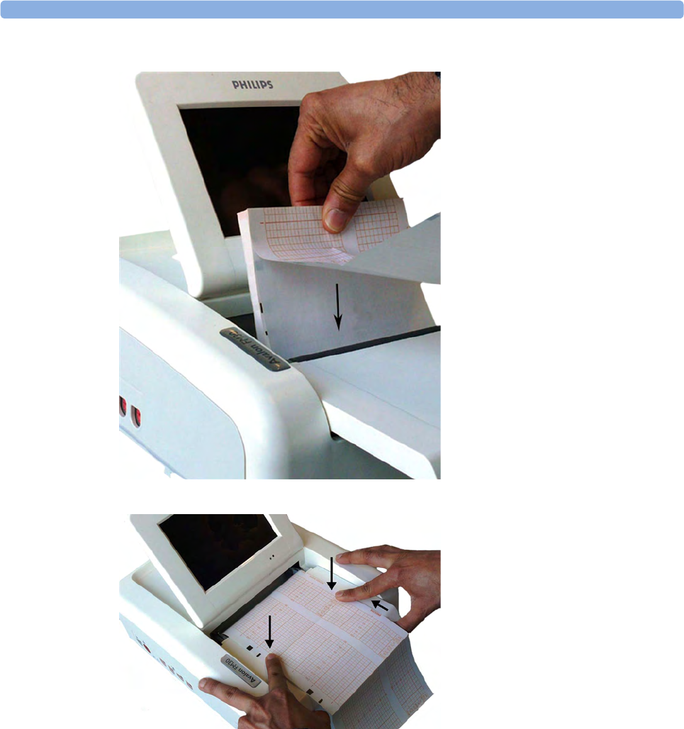
3 Basic Operation
64
5Unfold the top page of the pack and position the uterine activity scale on the right.
6Slide the pack into the tray.
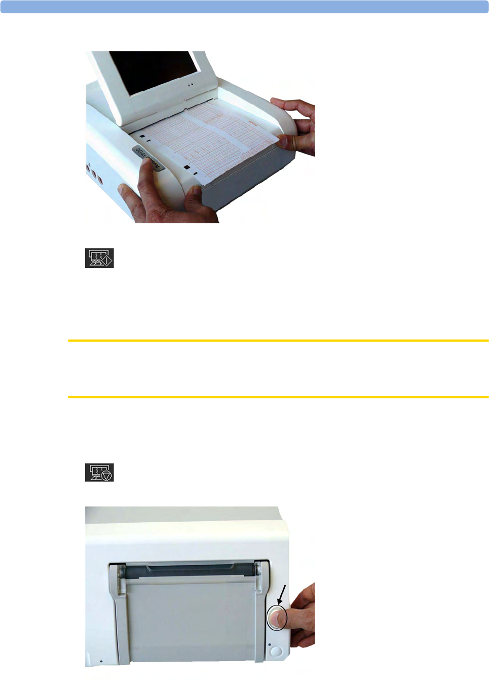
3 Basic Operation
65
7Push the paper drawer back until it "clicks" closed.
8Press the recorder Start/ Stop SmartKey or the Start Recordng SmartKey to switch on the recorder.
Annotations of trace information are printed on the trace paper (see “Switching the Recorder On and
Off” on page 56 for details).
Loading Paper FM40/FM50
CAUTION
Using recorder paper that is not approved by Philips can result in accelerated paper fading and can
damage the thermal line printhead. This type of damage is not covered by warranty.
FM40/FM50 To load a pack of paper:
1If the recorder is on, press the Start/ Stop Rec SmartKey or the Stop Recordng SmartKey to turn it
off before loading a new pack of paper.
2Press the paper eject button to open the paper drawer.
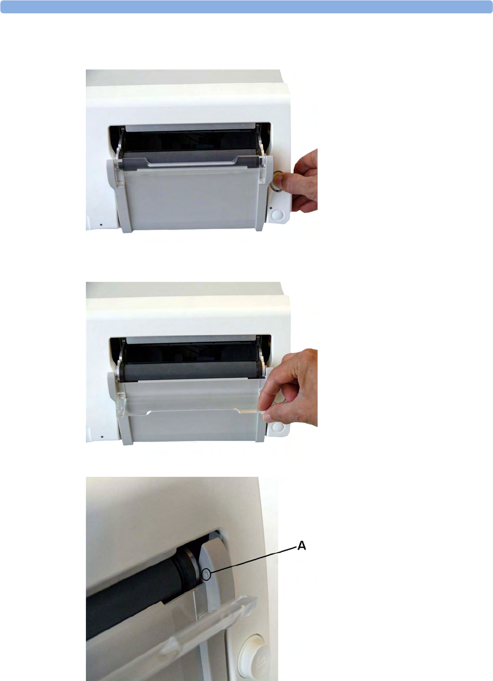
3 Basic Operation
66
3Lift out any remaining paper from the tray.
4Press and hold the paper eject button to partially eject the paper, thus making it easier to remove.
5Hinge the transparent paper guide forward. It is held in the closed position by a small protrusion
on each side of the holder.
A - Protrusion holds paper guide in closed position.

3 Basic Operation
67
6Prepare to place the new pack of paper in the tray with the bottom side down. The bottom side is
indicated by the word STOP printed on the final page of the new pack.
7Unfold the top page of the pack and position the uterine activity scale on the right.
8Slide the pack into the tray.
9Feed the paper evenly through the paper guide. Do not close the paper guide yet.
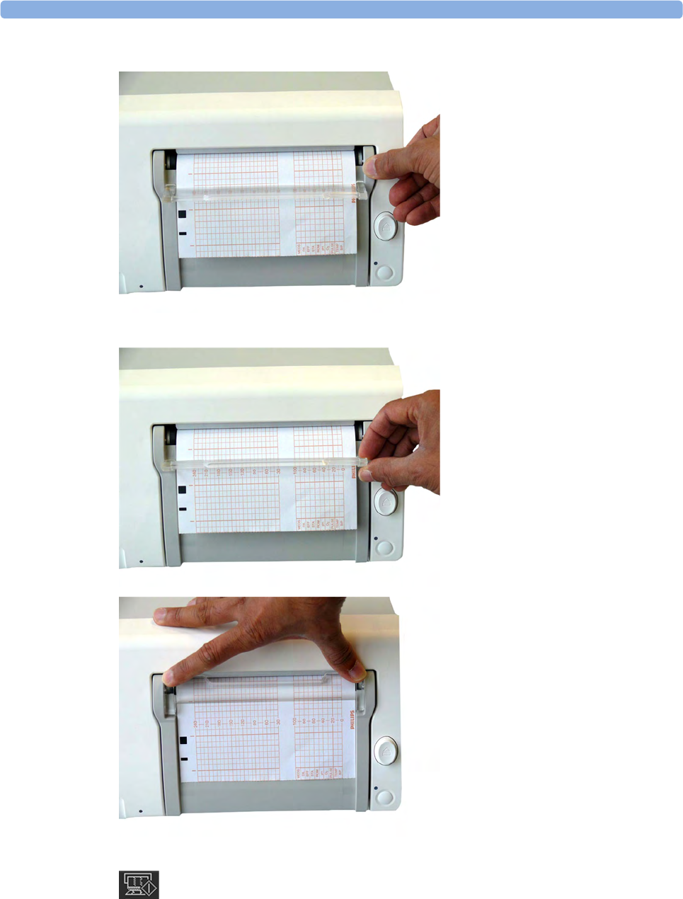
3 Basic Operation
68
10 Close the paper drawer.
11 Now close the paper guide.
12 Press the recorder Start/ Stop SmartKey or the Start Recordng SmartKey to switch on the recorder.
Annotations of trace information are printed on the trace paper (see “Switching the Recorder On
and Off” on page 56 for details).

3 Basic Operation
69
Entering Notes
Your monitor has a set of 15 factory pre-configured notes (see below). It is possible to edit these notes
in Configuration Mode (see the Configuration Guide). The maximum length of one single note is
30 characters.
To enter a note:
1Select the Enter Notes SmartKey to open the Enter Note menu.
2Scroll if necessary, then select the note you wish to enter. A confirmation dialog box opens:
3Select Confirm to enter the note. The note is then shown in the status line of the display, and is
annotated on the fetal trace if the fetal recorder is on.
4By default, notes are printed lengthwise in the direction of the trace, in the space between the FHR
grid and the uterine activity grid. If you prefer, you can configure the recorder to print across the
trace. You can change this in Configuration Mode.
The following are the pre-configured notes from which to choose:
1Patient Repositioned
2Vaginal Examination
3MD Notified
4Sitting
5On Back
6Left Lateral
7Ambulating
8Tocolytic Given
9Membranes Ruptured
10 Amniotomy
11 Amniotic Fluid Clear
12 Amniotic Fluid Not Clear
13 Oxytocin
14 Urinary Catheter
15 Micro Blood Analysis
Up to two notes can be printed directly, and the monitor can temporarily store up to a further two
notes, and these are printed after the first two have been printed. Any further notes are discarded. For
example, if you enter six notes in quick succession, the first two notes you entered are printed right
away, the next two are stored in memory and then printed when the first two have been printed, and
the last two are discarded.
If the printing of two notes happens to coincide with the regular printing of the time stamp that takes
place once every ten minutes, the time stamp is delayed until the notes have finished printing.

3 Basic Operation
70
Typing Notes
Other than the pre-configured notes selectable in the Enter Note menu, a note can be typed in
manually.
To type a note:
1Select the Enter Notes SmartKey to open the Enter Note menu.
2Select Type a note and a window with a touch keypad opens.
3Type the note and select Enter. The typed note can be up to 30 characters long. The note is shown
in the status line of the display, and is annotated on the fetal trace if the fetal recorder is on.
NOTE
The typed note remains in the window until it is deleted by using the backspace button of the
keyboard.
Signal Quality
During monitoring, if the fetal heart rate signal quality fluctuates, and becomes poor, it does not
necessarily mean that the transducer needs repositioning. The fluctuation may be caused by fetal
movement. Allow time for the signal to stabilize before deciding whether to reposition the transducer
(ultrasound), or apply a new electrode (ECG). For the best trace quality, the signal quality indicator
should be full, indicating good signal quality, even though it may be possible to make traces at a lower
signal quality level.
After Monitoring
Wired and cableless transducers
1Discharge the patient.
2Remove the transducer from the patient and, using a soft tissue, remove any gel from it. Then
clean the transducers.
3Dock CL transducers to the base station so they can recharge.
4Tear off the paper at the fold. To avoid misalignment of the recorder mechanism, NEVER pull on
the paper to advance it, or try to tear it other than at a fold (unless using the paper guide with the
FM40/FM50).
5Switch off the monitor.
NOTE
If an Avalon CL base station is connected to your FM20/30 monitor, do not turn off the monitor if
you need to recharge the batteries of the CL transducers. They can only be recharged if the FM20/30
monitor is on. If an Avalon CL base station is connected to an FM40/50 at the Telemetry ports in the
rear, the batteries of the CL transducers can be recharged while the monitor is not switched on. If you
disconnect a base station from a fetal monitor when the CL transducers are not fully charged, the base
station starts beeping. If you want to still disconnect it, confirm your choice by pressing the Standby
key of the base station, and the beeping stops.

3 Basic Operation
71
Switching the Monitor to the Standby Screen
To switch the monitor to the Standby screen:
Either
1Select the Monitor Standby SmartKey.
Or
1Enter the Main Setup menu using the SmartKey.
2Select Monitor Standby.
3Pressing any key or selecting any field on the screen will resume monitoring.
Disconnecting from Power
FM20/30
To disconnect the monitor from AC power, switch the monitor off using the On/Off switch located
on the right side of the device, or unplug the power cord from the AC mains socket.
FM20/FM30 with Battery Option and FM40/FM50
The On/Standby button does not disconnect the monitor from the AC power source. To disconnect,
unplug the power cord from the AC mains socket. Note that if the power cord is unplugged from the
AC mains socket before the monitor is put into Standby, a beeper is activated. The beeper warns you if
the monitor is accidentally disconnected from AC mains.
External Power Supply for the Avalon CL Base Station
To disconnect, unplug the power supply from the AC mains socket. Note that if the power supply is
unplugged from the AC mains socket before all CL devices are fully charged, a beep is issued. To
confirm the disconnection from power, and to silence the beep, press the On/Standby button of the
CL base station.
Power On/Power Off Behavior
The general rules determining the behavior of the fetal monitors when connected to, or disconnected
from power are as follows:
• A fetal monitor that was switched on prior to a temporary power loss, switches on again when
power is restored.
• A fetal monitor that was switched off prior to a temporary power loss, remains off when power is
restored.
• When AC mains power is lost, a battery powered monitor (FM20/30) continues to run without
interruption on battery power.

3 Basic Operation
72
Monitoring After a Power Failure
• A fetal monitor that was switched on prior to a temporary power loss, switches on again when
power is restored.
• A fetal monitor that was switched off prior to a temporary power loss, remains off when power is
restored.
• If the fetal monitor is without power for less than one minute, monitoring will resume with all
active settings unchanged.
• If the fetal monitor is without power for more than one minute, the behavior depends on your
configuration.
–If
Automat. Default is set to Yes, the default profile will be loaded when power is restored.
–If
Automat. Default is set to No, all active settings are retained, if power is restored within
48 hours. The Automat. Default setting is made in Configuration Mode.
Troubleshooting
Problem Possible Causes Solutions
Light or no trace Wrong paper Use recommended paper
Dirty printhead Clean printhead, see “Cleaning the
Print Head” on page 273
FM20/30 only: Paper misaligned due
to drawer not being correctly shut
Shut the drawer fully, pushing evenly
with both hands
End of paper noted when pack not
finished
Bad paper feed or wrong paper Check paper feed and use
recommended paper
Check Paper INOP is displayed INOP messages always indicate
equipment problems
See “Patient Alarms and INOPs” on
page 129
FetRec Equip Malf INOP is displayed
Paper End INOP is displayed
Wrong Paper Scale INOP is displayed

4
73
4Cableless Monitoring
Avalon CL Transducer System
The Avalon CL Fetal Transducer System lets you monitor the patient continuously with cableless
transducers during the antepartum period, labor, and delivery.
You can monitor the fetal heart rate (FHR):
• Using noninvasive CL Ultrasound transducers
• Invasively, using the CL ECG/IUP transducer or CL Toco+ MP transducer with a fetal scalp
electrode
• Noninvasively, with the CL F&M Pod
The uterine activity can be monitored using:
• Externally, using the CL Toco+MP transducer
• Externally, using the CL F&M Pod
• Invasively, using the CL ECG/IUP transducer or CL Toco+MP with an IUP catheter
The fetal and maternal parameters are measured and transmitted via radio frequency from the
CL transducers and CL Pods to the CL base station, eliminating the need for patient cables. With the
Avalon CL Transducer System, you can monitor a single fetus, twins, and triplets.
The Avalon fetal monitor (FM20-FM50) connected to the CL base station displays and records the
parameters. All the CL transducers and the CL F&M Pod are watertight. The IntelliVue CL Pods
should not be immersed in water. You can continuously monitor patients in a bath or shower using the
CL Toco+MP and the CL Ultrasound transducers, the CL F&M Pod should not be used during a bath.
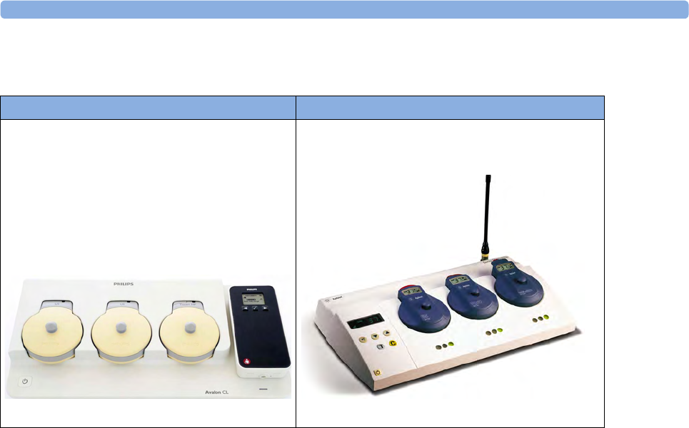
4 Cableless Monitoring
74
Basics of Cableless Systems
Assigning Cableless Devices
The cableless devices of the Avalon CL are assigned by simply docking them at the base station
connected to the patient’s fetal monitor. See the Avalon CTS Instructions for Use for the assignment
of the CTS transducers.
Activating Cableless Devices
The CL devices of the Avalon CL are activated by picking them up from the base station. If the
CL devices are activated, a corresponding symbol is displayed on the fetal monitor screen next to the
numeric of the measurement. See the Avalon CTS Instructions for Use for the activation of the
CTS transducers.
Deactivating Cableless Devices
The CL devices of the Avalon CL are deactivated by redocking them at a base station. To deactivate all
cableless devices at once, press the Standby key of the Avalon CL base station. See the Avalon CTS
Instructions for Use for the deactivation of the CTS transducers.
Unassigning Cableless Devices
The CL devices of the Avalon CL are unassigned by manually removing them in the corresponding
setup menu from the group of assigned cableless devices, or by unassigning them directly in the Tele
Info window. See the Avalon CTS Instructions for Use for the unassignment of the CTS transducers.
Avalon CL Transducer System Avalon CTS Transducer System

4 Cableless Monitoring
75
Twins and Triplets Support
Configuration of Cableless Systems
You have to configure the radio channels of the Avalon CL and Avalon CTS transducer system for
communication to work, and not to interfere with any other telemetry devices.
The configuration of a connected Avalon CL system is done in Configuration Mode or Service Mode
of the fetal monitor. Service Mode functions can be used to identify channel assignment conflicts in
the hospital environment. The configuration should be carried out by authorized and qualified service
personnel, either by the hospital's biomedical department, or by Philips Support.
For a detailed description of the configuration see the Avalon CL Service Guide and the Fetal Monitor
Configuration Guide. For details regarding the configuration of a connected Avalon CTS system see
the Avalon CTS Service Guide.
Fetal Movement Profile
When using an Avalon CL or Avalon CTS you should be aware that monitoring FMP is not
recommended when the mother is likely to move, and you should disable Fetal Movement Profile
(FMP) on the fetal monitor (Fetal Movement Off) if the mother is walking. Maternal movements are
likely to create artifact in the FMP output. See also “Switching FMP On and Off” on page 171, the
sections “Cableless Monitoring - Important Considerations” on page 167, and “Fetal Movement
Profile” on page 170.
Twins and Triplets Singletons only
Avalon CL Transducer System and
CL transducers
Avalon CTS System
Avalon CL Transducer System with
CL Fetal & Maternal Pod
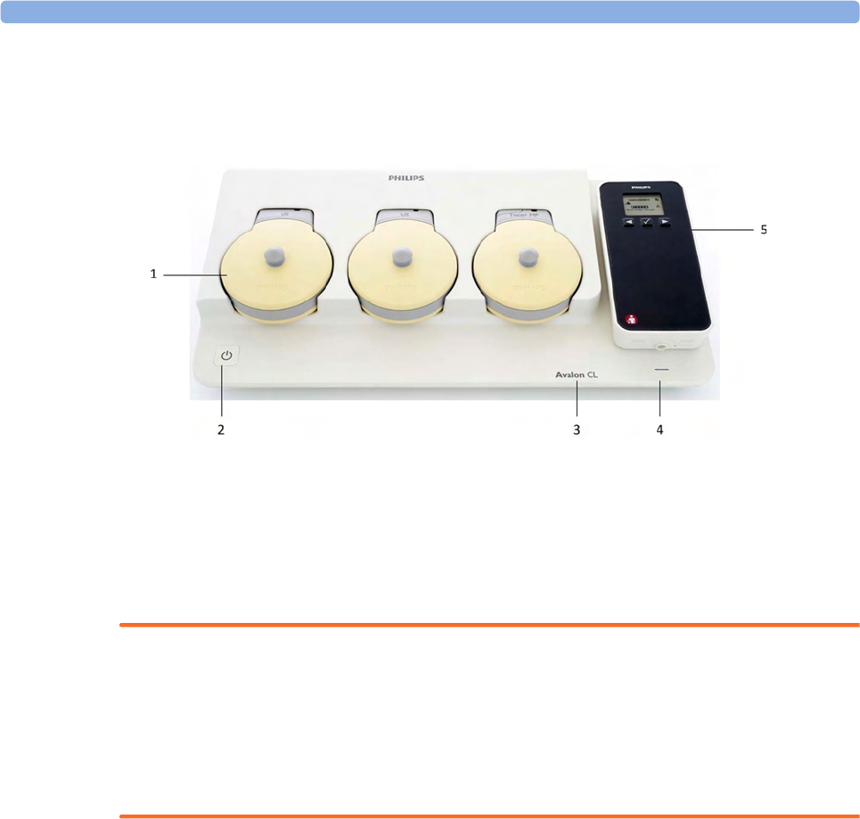
4 Cableless Monitoring
76
Getting to Know Your Avalon CL
Front
1Transducer docking slots
2On/Standby button with LED
3Device label
4LED for optional cableless Pods
5Docking slot for cableless Pods
WARNING
• To avoid magnetic interference affecting the mode of the pacemaker, ensure that the Avalon
CL base station does not come into close contact with implanted pacemakers.
• This equipment generates, uses, and radiates radio-frequency energy, and if it is not installed and
used in accordance with its accompanying documentation, may cause interference to radio
communications. Operation of this equipment in a residential area may cause interference, in
which case you must take whatever measures may be required to correct the interference.

4 Cableless Monitoring
77
Docking Slots for Cableless Transducers
The Avalon CL base station has three docking slots to hold the CL transducers. The transducers are
charged while docked. The base station has a built-in radio interface with an integrated antenna to
communicate with the transducers.
On/Standby Button
Pressing the On/Standby button switches the Avalon CL base station between the two modes On and
Standby.
If you switch the base station to On, the LED button lights up green. The base station is ready for use.
When the transducers are picked up from their docking slot, the base station sets up the radio
communication to the CL transducer automatically. Wired transducers connected to the fetal monitor
are disabled, and the antenna symbol for the CL transducer is displayed on the screen of the fetal
monitor.
If you switch the base station to Standby, the LED button turns off. The base station is now in
Standby mode. No radio communication occurs, any existing radio communication is stopped.
If the LED of the On/Standby button turns red, it indicates a technical problem has occurred that
needs your attention. Check your monitor for a possible related INOP message.
1On/Standby button
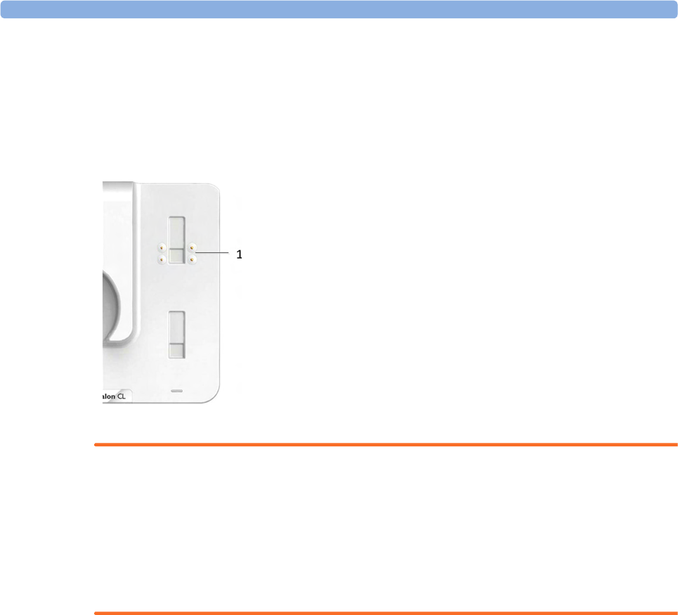
4 Cableless Monitoring
78
Docking Slot for Cableless Measurement Pods
The Avalon CL base station has one docking slot to hold a CL F&M Pod or an IntelliVue CL Pod.
The CL Pod is charged while docked. The LED under the docking slot indicates the battery status of
the CL Pod. The base station has a built-in short range radio interface with an integrated antenna to
communicate with the CL Pod.
WARNING
Short range radio connections are subject to interruption due to interference from other radio sources
in the vicinity, including microwaves, bluetooth devices, WLAN devices (802.11b,g,n), and cordless
phones. Depending on the strength and duration of the interference, the interruption may occur for an
extended period. A loss of connection, due to moving out-of-range, interference, or for other reasons,
is indicated with a No Host Monitoring INOP (here the host is the fetal monitor) on the NBP or
SpO2 Pods, or a cl NBP Disconnect or cl SpO₂ Disconnect INOP at the fetal monitor. Correct channel
configuration is important, see the Configuration Guide for details.
Audio Signal CL Base Station
The Avalon CL base station has two audio signals:
• If the base station issues a descending tone sequence, the attempt to set up radio communication
to a CL transducer or CL Pod has failed.
• The base station issues a permanent beeping tone if it is disconnected from a fetal monitor, or if
the FM20 or FM30 monitor is switched off, and the base station has transducers or a Pod
currently docked that need to be recharged.
Alarming is only available at the Avalon Fetal Monitor, not at the Cableless Measurement Devices, see
the Instructions of Use for the IntelliVue Cableless Measurements.
1Docking slot for CL Pods
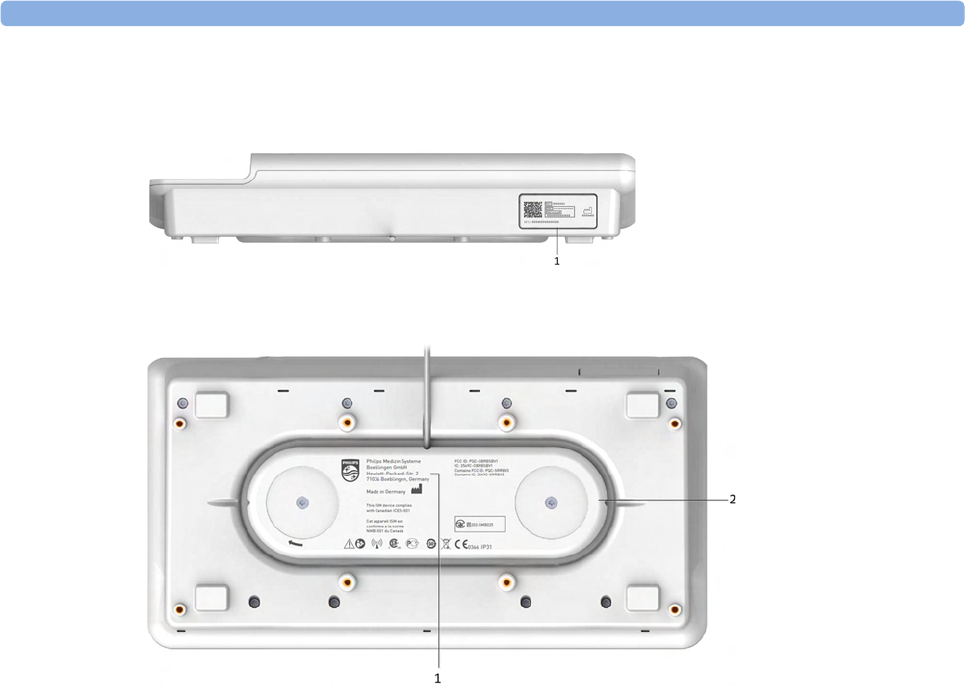
4 Cableless Monitoring
79
Rear and Bottom
1Name plate
1Manufacturer label
2Cable reel
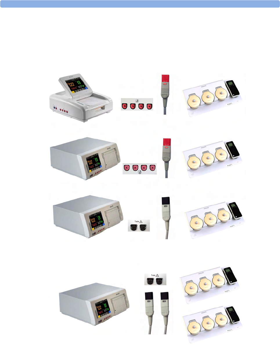
4 Cableless Monitoring
80
Connection Options
The fetal monitors FM20/FM30 and FM40/FM50 are compatible with the Avalon CL and Avalon
CTS Transducer Systems. Regard the following points for cableless monitoring:
• You can connect one Avalon CL base station with a red connector to an FM20/FM30 or an
FM40/FM50 (fetal socket), or one Avalon CL base station with a black connector to an FM40/
FM50 (telemetry socket).
• You can connect two Avalon CL base stations with black connectors to an FM40/FM50
(telemetry sockets)
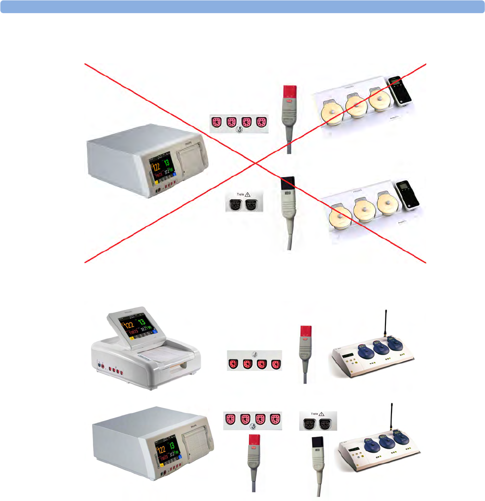
4 Cableless Monitoring
81
•You cannot connect two Avalon CL base stations to an FM40/FM50, if one Avalon CL base
station has a red connector, and the other Avalon CL base station has a black connector.
• You can connect one Avalon CTS system to an FM20/FM30 or FM40/FM50 at a time (either
fetal or telemetry socket).
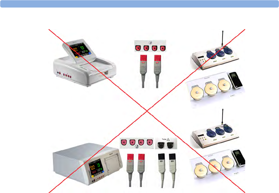
4 Cableless Monitoring
82
•You cannot connect an Avalon CTS and an Avalon CL at the same time to the same fetal monitor.
• Monitoring a multiple pregnancy using cableless transducers is supported by the Avalon CL system
only.
• Using a mixture of wired and cableless fetal transducers is not supported. You can use either wired
or cableless fetal transducers.
• If you cannot get sufficient signal quality using Avalon CTS transducers, switch to wired
transducers.
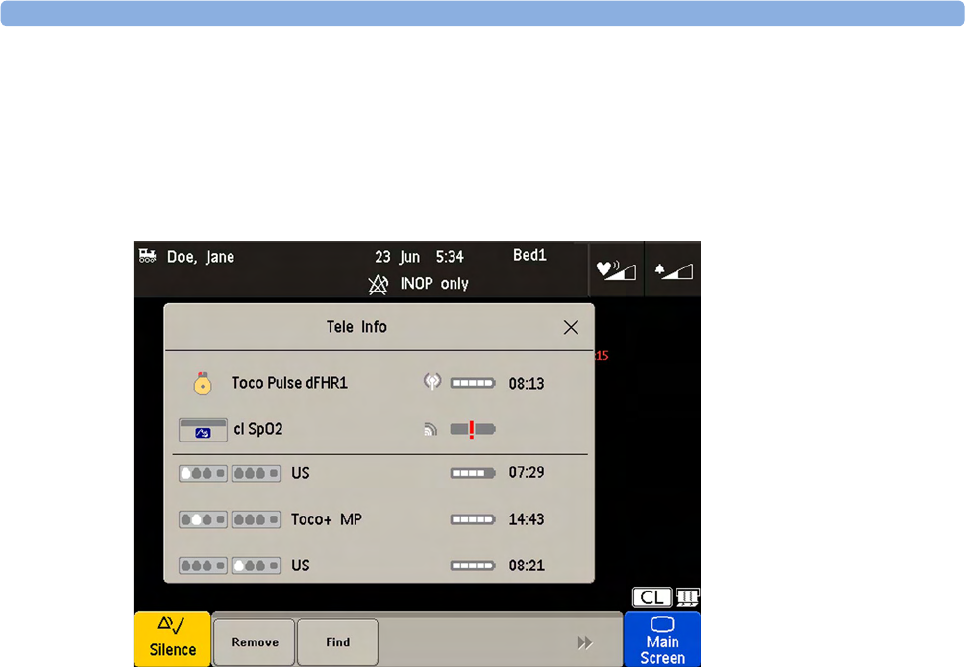
4 Cableless Monitoring
83
Connecting Two CL Base Stations to an FM40/50 Monitor
Two base stations can be connected to an FM 40/50 fetal monitor at the rear black telemetry ports. At
both base stations CL transducers and CL Pods can be assigned, activated, and redocked for charging.
The base stations work as one extended system together. Pressing the Standby key of either base
station, puts both base stations in Standby mode. The Tele Info window shows both base stations in
operation.
External Power Supply (Option K60)
In combination with the optional external AC power supply an Avalon CL base station serves only as
a charging station for Avalon CL transducers and IntelliVue CL Pods, and all radio communications
are disabled. The On/Standby button of the base station lights up white in this operation mode. The
charging indication of the LEDs of the docked CL transducers and the IntelliVue CL Pods remain the
same as described in the sections “Cableless Transducer LED Indication” on page 86 and “Battery
Status LED for CL Pods” on page 93.
When a transducer is picked up from the base station after charging, it needs to be activated for
monitoring by docking it on a CL base station connected to the patient's fetal monitor.
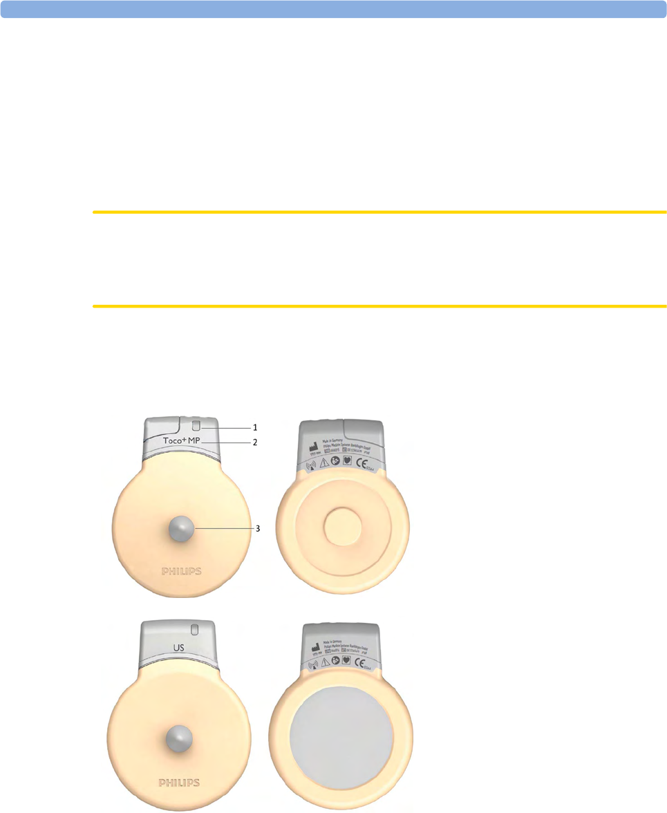
4 Cableless Monitoring
84
Cableless Transducers
The cableless Avalon CL transducers have a built-in radio interface with an on-board, integrated
antenna. The fetal monitor connected to the Avalon CL base station can control the transducer using
radio communication. The CL transducer transmits measured values, alarms, and status information to
the fetal monitor.
The CL transducers are assigned by simply docking them at the Avalon CL base station. If they are
picked up from their docking slot at the base station, they are automatically activated.
CAUTION
To ensure the correct assignment of CL transducers to the fetal monitor in use, always dock them at
the base station connected to that fetal monitor before use. This is particularly important when you
add an additional CL transducer that was previously docked at another base station.
NOTE
Avoid dropping the transducers.
1Transducer finder LED - lights
up on the transducer providing
the measurement source.
2CL Toco+ MP transducers
(capable of providing the
maternal pulse measurement)
3Belt button
CL Ultrasound transducer
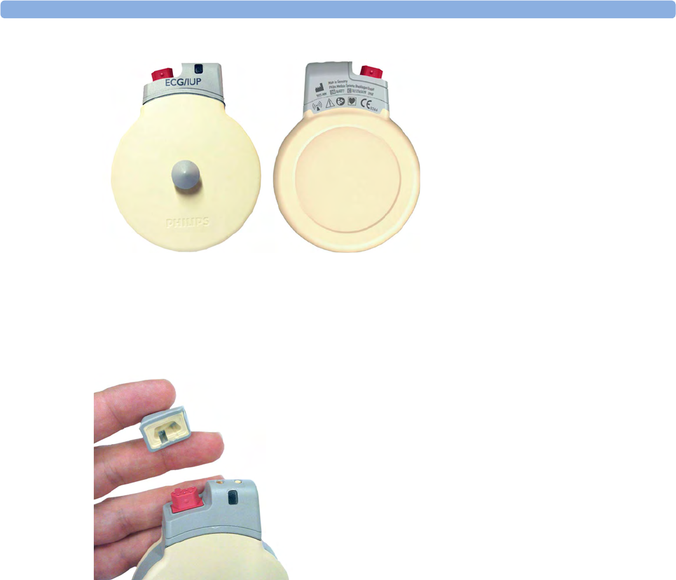
4 Cableless Monitoring
85
Connector Cap for the CL Toco+ MP Transducer
The CL Toco+ MP transducer is delivered with a connector cap covering the MECG/DECG/IUP
connector. The connector cap is designed to cover the connector, not to protect it from water. (The
connector itself is water-proof and may be immersed in water).
CL ECG/IUP transducer

4 Cableless Monitoring
86
Cableless Transducer LED Indication
The cableless transducers have a multi-color LED that indicates the status of the transducer with
specific colors. This LED remains visible when the transducer is correctly attached to the transducer
belt (Philips standard belt).
1LED
LED Status Meaning
White The LED lights up to identify the transducer among other transducers,
and to easily verify the correct transducer assignment (transducer finder).
The transducer finder LED is controlled by the fetal monitor. Press the
numerics to identify the corresponding transducer.
The LED also lights up when the mother is paged with the Call Patient
SmartKey.
White one short blink The LED shortly lights up to indicate that the transducer successfully
opened a radio communication with the base station and that it is ready to
use.
Green The LED lights up green when the transducer is fully charged and docked
at the base station.
Yellow The LED lights up yellow when the transducer is charging and docked at
the base station.
Red The LED flashes red when the transducer is out of battery and has to be
recharged.
When a docked transducer performs an update, the LED will blink fast
red for about 1 minute. In this case, do not remove the transducer until
the LED lights up green or yellow again.
Cyan The LED lights up cyan to indicate a technical problem that needs your
attention. Check your fetal monitor for a related INOP.

4 Cableless Monitoring
87
Audio Signal CL Transducers
The Avalon CL transducers have three audio signals:
• If an ascending tone sequence is played three times, the transducer was triggered by the fetal
monitor to page the patient wearing it, or to locate a not docked transducer.
• If the CL transducer's battery is empty, the transducer issues three beeps in intervals.
• An INOP tone indicates that the transducer has detected a technical problem (INOP). Check your
fetal monitor for a related INOP message.
Standard Radio Range of CL Transducers
The CL transducers have an operating range around the base station of at least 100 m/300 ft in the
line of sight. Obstructions such as walls, metal doors, elevators, and other environment structures can
lead to signal loss. The CL symbol indicator and the Tele Info window on the monitor's display (see
“Screen Elements” on page 39 and “Tele Info Window” on page 94) provide information on the
status of the signal strength.
When a patient is approaching the end of range, the US sound is replaced by an artificial QRS sound
(like DECG), and the DECG and MECG waves are no longer displayed on the monitor.
Out of Range
If the patient walks out-of-range, the CL transducer LED lights up cyan and every 16 seconds a two-
tone audio signal is emitted. At the monitor the INOP e.g. cl US Disconnect is issued. Inform the
patient to return to the CL base station, when a CL transducer starts beeping.
Radiated Transmission Power
The Avalon CL transducers provide all the benefits and flexibility of cableless operation, but do so
with an effective radiated transmission power significantly less than that of a typical remote controlled
child’s toy or mobile phone.
Extended Range Radio
Using the optional CL Wide Range Pod extends the radio range of the CL transducers and the
CL Pods to the local WLAN infrastructure. If the CL Wide Range Pod is active, the US sound is
replaced by an artificial QRS sound (like DECG), and the DECG and MECG waves are no longer
displayed on the fetal monitor. Numerics, alarms, and traces are shown at the fetal monitor as usual.
See also “CL Wide Range Pod” on page 91.
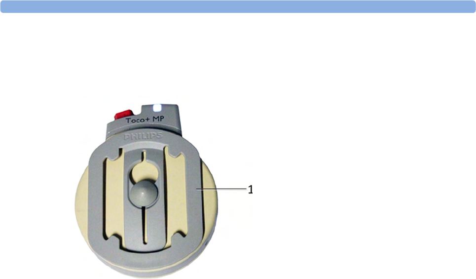
4 Cableless Monitoring
88
Using CL Transducers with a Belt Clip
The Avalon CL transducers can also be used with an optional belt clip to be ordered separately
(989803184851).
1Avalon CL belt clip
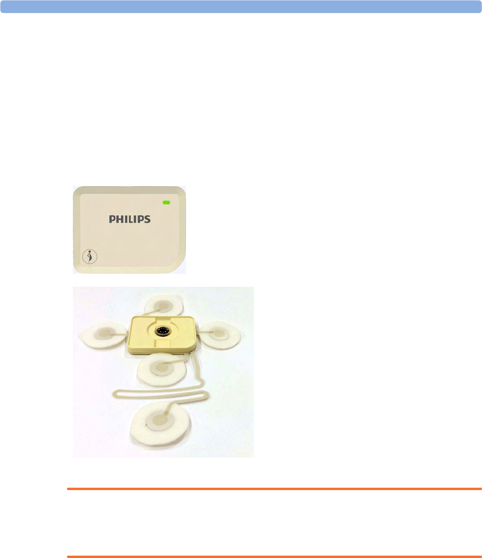
4 Cableless Monitoring
89
CL Pods
CL Fetal & Maternal Pod
The CL F&M Pod provides measurement values for FHR, Toco, and HR. It communicates them to
the fetal monitor using short range radio (SRR). It is controlled via SRR from the Avalon CL base
station and the connected fetal monitor.
The CL F&M Pod is assigned by docking it at the Avalon CL base station. Before monitoring, the
CL F&M Pod is mounted on a single-use electrode patch, and held in place by integrated magnets.
When the CL F&M Pod is active, the wired transducers connected to the fetal monitor are disabled.
WARNING
The CL Fetal & Maternal Pod has been validated with a gestational age of >36 weeks with patients in
labor. It is only intended for singleton pregnancies. If the measurement signals are not good or in any
way suspicious, use other means of monitoring (CL transducers or wired transducers).
CL F&M Pod
CL F&M Patch
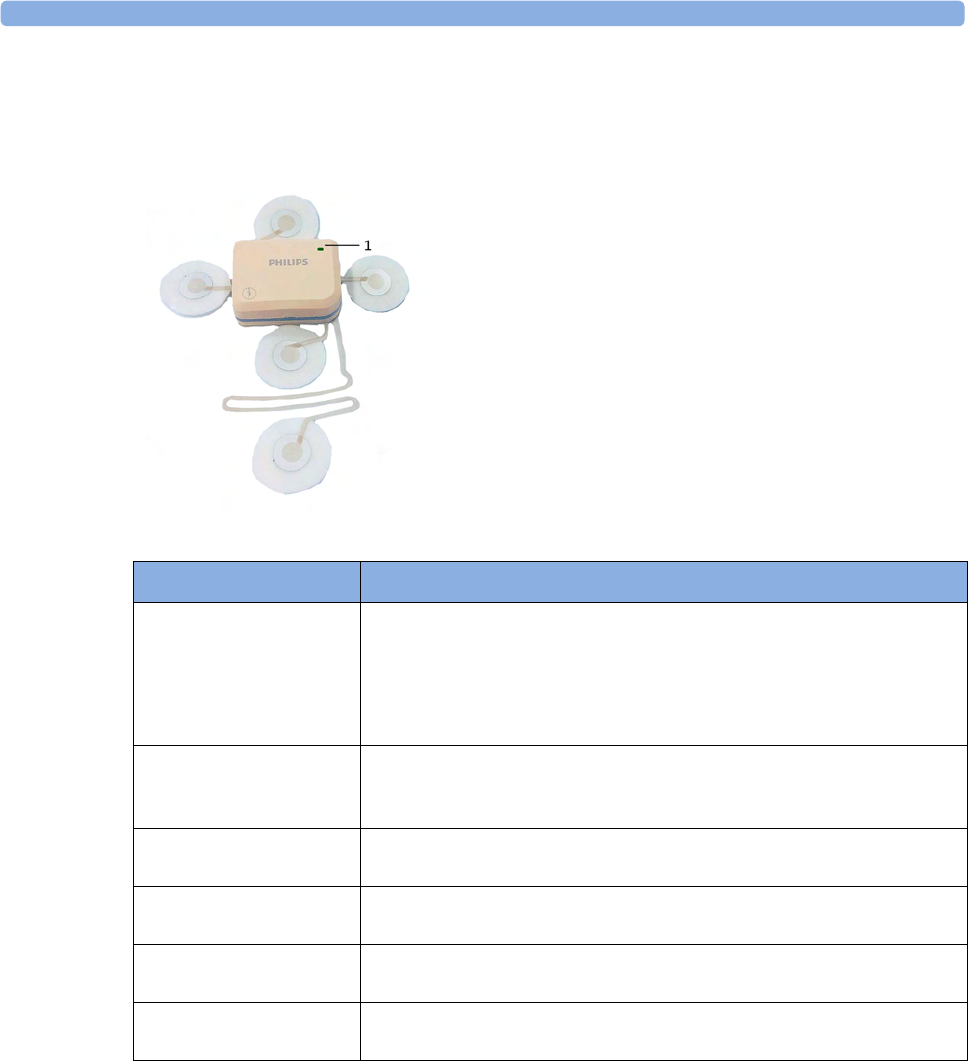
4 Cableless Monitoring
90
CL Fetal & Maternal Pod LED Indication
The CL F&M Pod has a multi-color LED that indicates the status of the CL F&M Pod with specific
colors.
Audio Signal CL Fetal & Maternal Pod
The Avalon CL F&M Pod has three audio signals:
• If an ascending tone sequence is played three times, the CL F&M Pod was triggered by the fetal
monitor to page the patient wearing it, or to locate a not docked CL F&M Pod.
• If three beeps are issued at intervals, the CL F&M Pod's battery is empty.
• An INOP tone indicates that the CL F&M Pod has detected a technical problem (INOP). Check
your fetal monitor for a related INOP message.
1LED
LED Status Meaning
White The LED lights up to identify the CL Pod, and to easily verify the correct
assignment (finder). The finder LED is controlled by the fetal monitor.
Select the numerics to identify the corresponding CL Pod.
The LED also lights up when the mother is paged with the Call Patient
SmartKey.
White, one short blink The LED briefly lights up to indicate that the CL Pod successfully
opened a radio communication with the base station and that it is ready to
use.
Green The LED lights up green when the CL Pod is fully charged and docked at
the base station.
Yellow The LED lights up yellow when the CL Pod is charging and docked at the
base station.
Red The LED flashes red when the CL Pod's battery is empty, and has to be
recharged.
Cyan The LED lights up cyan to indicate a technical problem that needs your
attention. Check your fetal monitor for a related INOP.
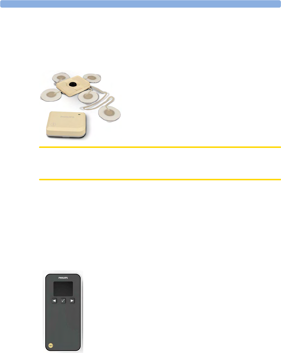
4 Cableless Monitoring
91
CL Fetal & Maternal Electrode Patch
The single-use disposable adhesive electrode patch holds the CL F&M Pod at the intended application
site on the abdomen of the patient. The electrode patch has five adhesive electrodes. The CL F&M
Pod is held in place during monitoring with magnetic contacts, and a connector. The electrode patch
and the CL F&M Pod can only be used together and within the Avalon Cableless Transducer System
solution for monitoring.
CAUTION
The electrode patch is single-patient use only, do not reuse the electrode patch on another patient to
avoid possible cross-infection.
CL Wide Range Pod
The Avalon CL Wide Range Pod is a battery-powered auxiliary network device that converts the SRR
and OB radio technology of Avalon CL transducers and the CL Pods into WLAN technology. This
allows data from the measurement devices to be transmitted to a fetal monitor while the patient is
ambulating.
The Avalon CL Wide Range Pod is a mobile device which can be worn by the patient or by an
attending caregiver. The display on the CL Wide Range Pod shows only technical data that may be
useful for troubleshooting system problems.
CL Wide Range Pod
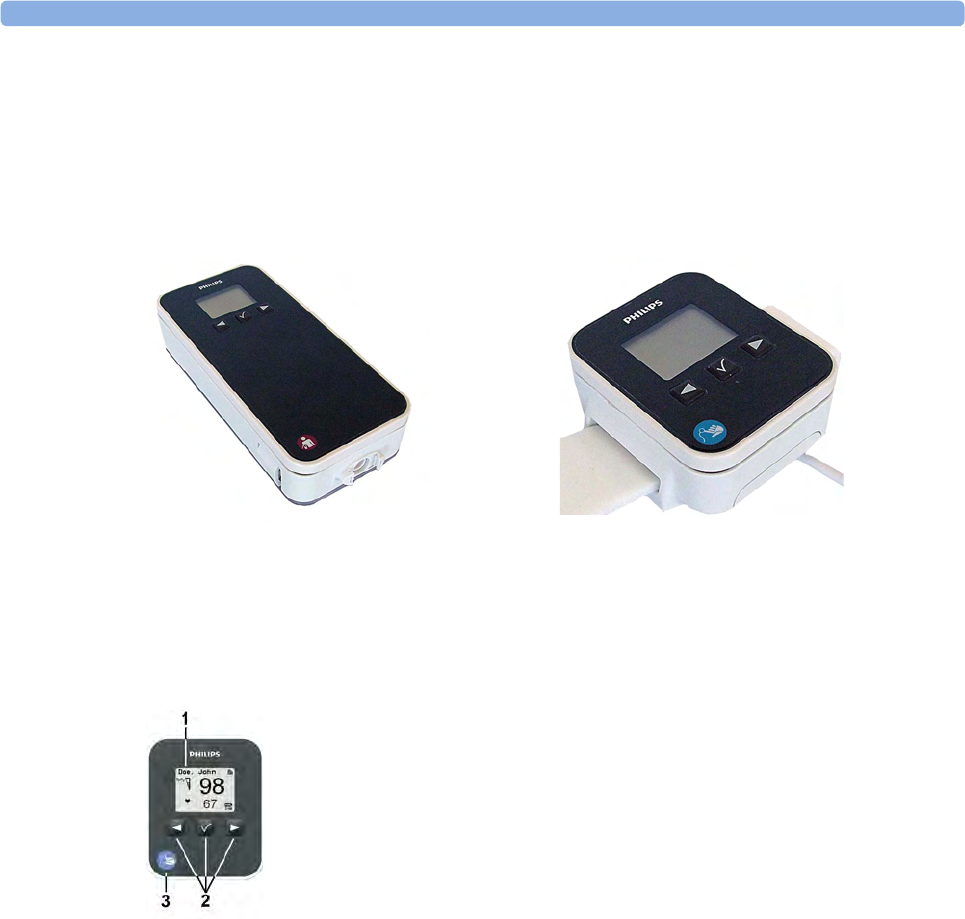
4 Cableless Monitoring
92
IntelliVue CL Pods
The two IntelliVue CL Pods provide measurement values for SpO2 and NBP on the built-in display,
and communicate them to the fetal monitor using short range radio (SRR). They are controlled with
SRR from the Avalon CL base station and the connected fetal monitor.
The maternal measurement pods are assigned by docking them at the Avalon CL base station.
The CL SpO2 Pod and the CL NBP Pod have an LCD display and three keys for basic operation e.g.
to assign the device to a patient:
For further details, see the IntelliVue Cableless Measurements Instructions for Use.
CL NBP Pod CL SpO2 Pod
1Integrated LCD display
2Hardkeys
3Measurement identifier
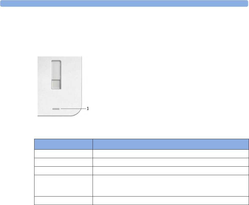
4 Cableless Monitoring
93
Battery Status LED for CL Pods
The CL Pods do not have their own battery status LED, but a small battery gauge on their display. On
the Avalon CL base station, the battery status LED for the CL Pods is located directly under the
docking slot.
The battery status LED shows five different states:
Audio Signal CL Pods
The CL Pods have audio signals to let you know when a battery has to be recharged. If a CL Pod's
battery is empty, the CL Pod issues three beeps at intervals.
Calling Patients
To call a patient currently not near the fetal monitor and base station, select the SmartKey Call Patient
at the fetal monitor. The base station will then select one transducer, or the CL F&M Pod if it is
assigned and active, to emit the tone sequence to notify the patient. Inform the ambulating patient, if
the cableless device is issuing any beeping sounds, to return to the room with the fetal monitor.
1Battery status LED for CL Pods
Status Meaning
Green The docked CL Pod is fully charged.
Yellow The docked CL Pod is charging.
Yellow blinking The communication is established with the docked CL Pod.
Cyan Indicates that the docked CL Pod or the charging slot has a technical
problem that needs your attention. Check your fetal monitor for a related
INOP message.
Off The battery status LED is off, when no CL Pod is docked.
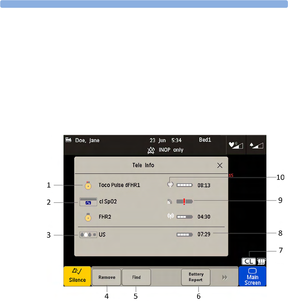
4 Cableless Monitoring
94
Telemetry
Tele Info Window
The Tele Info window of the fetal monitors allows you to manage the Avalon CL or CTS system.
Below is an exemplary view of the Tele Info window. Your window may differ depending on the status
of the connected system.
To open the Tele Info window, you can:
1Configure a Tele Info SmartKey to open the window,
2select the CL symbol on the main screen, or
3select the Main Setup and then Tele Info.
1CL transducer symbol assigned with the parameter labels
2Cableless measurement symbol and equipment ID
3Base station symbol with docking indication (the white slot indicates a charging transducer)
4Key Remove
5Key Find
6Key Battery Report (in Service Mode)
7CL symbol
8Remaining battery time
9Out of battery symbol
10 Indication of radio signal quality
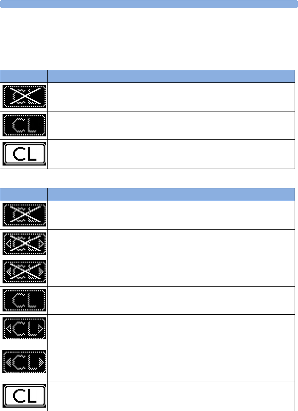
4 Cableless Monitoring
95
Cableless Status Indication
When the monitor recognizes a connected Avalon CL or Avalon CTS interface cable (red or black
connector), it confirms the recognition with the following status indicators displayed in the lower
right-hand corner of the screen:
Avalon CTS
Avalon CL
Indicator Description
Avalon CTS interface cable is connected to the monitor, but the Avalon CTS base station is not
connected to the interface cable, or it is disconnected from AC mains, or is in Standby mode.
Avalon CTS interface cable is connected to the monitor, Avalon CTS base station is connected,
powered on, and cableless transducers are ready to use, but no cableless transducers are currently
active (all are still docked at the base station).
Avalon CTS interface cable is connected to the monitor, Avalon CTS base station is connected,
powered on, and at least one cableless transducer is active and assigned.
Indicator Avalon CL
A base station is connected to the monitor, but the base station is in Standby mode.
A base station is connected to the monitor, but the base station is in Standby mode. The CL Wide
Range Pod is activated and trying to connect to the monitor.
A base station is connected to the monitor, but the base station is in Standby mode. The CL Wide
Range Pod is activated and connected to the monitor.
A base station is connected to the monitor but no cableless transducers and no cableless Pods are
currently active. All are still docked at the base station, or the base station holds no transducers.
A base station is connected to the monitor but no cableless transducers and no cableless Pods
(except the CL Wide Range Pod) are currently active. All are still docked at the base station, or the
base station holds no transducers. The CL Wide Range Pod is activated and trying to connect to
the monitor.
A base station is connected to the monitor but no cableless transducers and no cableless Pods
(except the CL Wide Range Pod) are currently active. All are still docked at the base station, or the
base station holds no transducers. The CL Wide Range Pod is activated and connected to the
monitor.
A base station is connected to the monitor, it is on, and minimum one assigned cableless
transducer or cableless Pod is active.
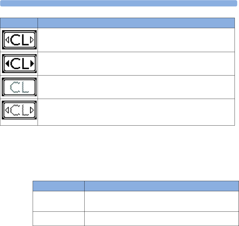
4 Cableless Monitoring
96
NOTE
A CL transducer is considered still active, even if it has an INOP condition (e.g. cl US Disconnect), until
it is either deactivated by docking it at the base station, or until it is manually removed from the Tele
Info window.
Pop-up Keys
Messages
The fetal monitor issues messages to certain user interactions. For example, if the CL SpO2 Pod is
picked up from the base station to activate it, the monitor displays the message cl SpO₂ Added and the
equipment label of the CL Pod.
A base station is connected to the monitor, it is on, and minimum one assigned cableless
transducer or cableless Pod is active. The CL Wide Range Pod is activated and trying to connect
to the monitor.
A base station is connected to the monitor, it is on, and minimum one assigned cableless
transducer or cableless Pod is active. The CL Wide Range Pod is activated and connected to the
monitor.
A CL transducer has moved away from the base station and is approaching the limit of the area of
reach (min. 100 m/300 ft in line of sight). The US sound is replaced by an artificial QRS sound
(like DECG). The DECG and MECG waves are no longer displayed.
A CL transducer has moved away from the base station and is approaching the limit of the area of
reach (ca. min. 100 m/300 ft in line of sight). The US sound is replaced by an artificial QRS sound
(like DECG). The DECG and MECG waves are no longer displayed. The CL Wide Range Pod is
activated and trying to connect to the monitor.
Indicator Avalon CL
Pop-Up key Function
Remove Selecting the Remove key deactivates and unassigns the selected active
transducer or CL Pod and removes it from the list. This key is disabled if no
active device is selected.
Find Selecting the Find key pages the selected active CL transducer. This key is
disabled if no active device is selected.

4 Cableless Monitoring
97
Use Priority When Combining Cableless and Wired Measurements
CL Transducers versus wired transducers
CL transducers have priority over wired transducers. If an Avalon CL or Avalon CTS base station is
connected to the fetal monitor, and both wired and CL transducers are connected to the monitor, all
the wired transducers are disabled whenever one CL transducer is active. To switch back to using
wired transducers, switch the base station to Standby mode, or redock all CL transducers at the base
station, and continue monitoring with the wired transducers.
CL NBP and CL SpO2 versus fetal monitor built-in NBP and SpO2 measurements
CL NBP and CL SpO2 have priority over the built-in NBP and SpO2 measurements. If a CL NBP or
CL SpO2 Pod is activated, the corresponding built-in measurement of the fetal monitor is deactivated.
To switch back to the built-in measurements, switch the base station to Standby mode, or redock the
CL Pods at the base station.
CL F&M Pod versus wired transducers
The CL F&M Pod has priority over wired transducers. If a CL F&M Pod is active, all the wired
transducers are disabled. To switch back to using wired transducers, switch the base station to Standby
mode, or redock the CL F&M Pod at the base station.
About RF Signal Quality
If you cannot get sufficient ultrasound signal quality using the Avalon CTS base station, try
repositioning the transducers, or switch to wired transducers.
Using an Avalon CL base station you should get a better signal by reducing the distance between the
CL transducer and the base station.
Signal transmission can be disturbed if:
• the patient is out of range of the receiving area.
• there is interference from another, possibly stronger, RF signal (a broadcasting station, for
instance).
• the patient is near material that absorbs electromagnetic waves (for example, metal-reinforced
concrete, elevator doors) or the base station is in an enclosed metal rack.

4 Cableless Monitoring
98
CL Transducer Assignment
The CL transducers are assigned by simply docking them at the Avalon CL base station connected to
the patient’s fetal monitor.
Since twins and triplets can be monitored with the Avalon CL base station, it can be delivered with up
to six CL transducers: one CL Toco+ MP, three CL US, and two CL ECG/IUP transducers. Up to
four CL transducer can be assigned at one time to the Avalon CL base station. Four assigned
CL transducers enable monitoring combinations such as 1 CL Toco+ MP transducer + 3 CL US
transducers for monitoring triplets externally, or 1 CL Toco+ MP transducer + 2 CL US transducer +
1 CL ECG/IUP transducer for monitoring twins.
Three CL transducers can be docked and charged at the Avalon CL base station at a time. If a fourth
transducer should be assigned to the Avalon CL base station:
1Remove first the three docked CL transducers from the base station and place them on the patient.
2Then dock the remaining fourth transducer at the base station and wait until the LED of the
fourth transducer signals that it has communication with the base station.
3Place the fourth CL transducer on the patient and check on the fetal monitor in the Tele Info
window if the base station and the monitor have communication with all four transducers, and if
their numerics are displayed on the screen of the fetal monitor.
CL Transducer Unassignment
The cableless transducer needs to be unassigned:
• before being used with another base station on another patient
• to allow cleaning before docking it back onto the base station (e.g. to replace it with a fully charged
transducer of the same type)
There are three methods to do this:
1Open the setup menu of the measurement e.g. FHR1 by selecting the numeric on the screen.
2Select Remove from the open setup menu.
3A confirmation window opens with the prompt Please Confirm and Device will be removed.
4Select the Confirm pop-up key. A message confirms cl US has been removed.
or
1Open the Tele Info window.
2Select the symbol of the cableless transducer you want to unassign, and select Remove from the
pop-up menu.
3A confirmation window opens with the prompt Please Confirm and Device will be removed.
4Select Confirm the pop-up key. A message confirms cl US has been removed.
or
1Redock the CL transducer at the base station.
2Switch the base station to stand-by.
3Remove the CL transducer; it is now unassigned.

4 Cableless Monitoring
99
NOTE
When a CL transducer is unassigned, all the measurements from this transducer are no longer
monitored; e.g. if you unassign a CL Toco+MP transducer, the Toco measurement, maternal Pulse, or
possibly also MECG or DECG are no longer monitored.
CL Pod Assignment
The CL Pods are assigned by simply docking them at the Avalon CL base station connected to the
patient’s fetal monitor.
CL Pod Unassignment
The CL Pods have to be unassigned:
• before assigning them to another base station or to another patient
• to allow cleaning, before docking them back onto the base station
There are three methods to do this:
1Open the setup menu of the measurement e.g. by selecting the numeric on the screen.
2Select Remove from the open setup menu.
3A confirmation window opens with the prompt Confirm and Device will be removed.
4Select the Confirm pop-up key. A message confirms <cl Measurement> has been removed.
or
1Open the Tele Info window.
2Select the symbol of the CL Pod, and select Remove from the pop-up menu.
3A confirmation window opens with the prompt Confirm and Device will be removed.
4Select the Confirm pop-up key. A message confirms <cl Measurement> has been removed.
or
1Redock the CL Pod at the base station.
2Switch the base station to stand-by.
3Remove the CL Pod; it is now unassigned.
To unassign a IntelliVue CL Pod using its user interface, see the Cableless Measurement
Instructions for Use.
NOTE
If you unassign a CL Pod, all the measurements from it are no longer monitored, or are monitored by
a connected lesser prioritized sensor.

4 Cableless Monitoring
100
Preparing to Monitor Cablelessly
When monitoring cablelessly with the FM20/30/40/40 monitors, most of the same procedures apply
as described in “Preparing to Monitor” on page 48. Additions and deviations applying to cableless
devices and existing procedures are described here.
CL Transducers
1To monitor cablelessly with the CL transducers, assign them at the base station as described in
“CL Transducer Assignment” on page 98.
2Place the CL transducers and the belt on the patient described in “Fastening Belts and
Transducers” on page 50.
3Check the measurements on the monitor, and if necessary, move the CL transducers until you have
a good signal for all measurements.
IntelliVue CL Pods
1To monitor cablelessly with the IntelliVue CL Pods, assign them at the base station as described in
“CL Pod Assignment” on page 99.
2Put the CL Pods in their cradles and place them on the patient as described in the IntelliVue
Cableless Measurements Instructions for Use.
Applying the CL Fetal & Maternal Patch and Pod
WARNING
Do not use the CL Fetal & Maternal Pod and electrode patch for monitoring if:
• The skin on the abdomen of the patient has established erythema, lesions, infection, inflammation,
or any kind of injuries at the applications site
• The patient has a history of skin irritation, allergies, or hypersensitivity to adhesives
• The patient carries multiple fetuses
• The gestational age is less than 36 completed weeks. The measurement method is also only
validated with patients in labor.
CAUTION
During handling, avoid close contact of the CL Fetal & Maternal Pod or the electrode patch to an
implanted pacemaker or defibrillator.

4 Cableless Monitoring
101
At the Mother's Side
1Have a new single-use electrode patch ready, and make sure that the pouch is still intact. Check the
expiration date that is printed on the pouch.
2Clean the application area on the abdomen of the patient. Use mild soap to wash any cream, oil, or
gel from the abdomen. Make sure to thoroughly wipe the area dry afterwards, ideally using paper
towels.
3Take the electrode patch from its pouch.
4Study the electrode patch Instructions for Use showing the correct placement of the electrode
patch on the abdomen of the patient.
5Remove the cover from the adhesive area under the central area of the patch. (Do not remove the
cover from any of the five surrounding electrodes yet).
6Verify the correct orientation of the patch. The “Philips/Monica” printed top electrode must point
to the patient’s chest.
7Place the central adhesive area of the patch over the patient’s umbilicus as shown in the patch
Instructions for Use. Then press it down.
For patients with a displaced umbilicus:
Where the umbilicus has been displaced downwards, position the center of the patch along the
midline, where it intersects the horizontal line passing over the iliac crests. Alternatively, estimate
the mid-point between the fundus and symphysis pubis.
For very obese patients or patients with a large panniculus:
An alternative strategy is to position the patch along the midline such that the edge of the top
electrode is placed 10-12 cm (4-5 in) below the fundus.
8Lift up one of the four electrodes. Identify the small area of the skin where you will place the
center of the electrode.
9Use one piece of abrasive ECG skin preparation paper to prepare the patient's skin. Make three
horizontal and three vertical strokes with the skin preparation paper. Focus the strokes on the
small area of the skin where the conductive center of the electrode will be placed. Make deliberate
but gentle strokes, lifting the finger after each stroke.
CAUTION
Do not use too much pressure with the abrasive skin preparation paper to avoid skin injury.
10 Remove the protective cover from the electrode. Place the electrode on the prepared skin. Press it
down firmly, but avoid pressing the central gel area of electrode.
11 Repeat the steps for the skin preparation and electrode placement for the other three electrodes.
incorrect correct
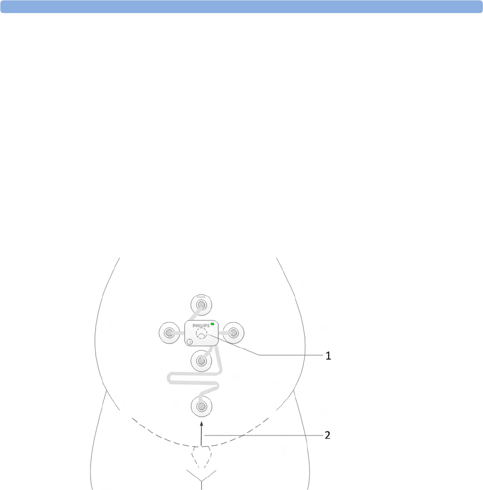
4 Cableless Monitoring
102
12 For the last remaining electrode attached to the long flexible cable, identify the small area of skin
to prepare, so that the center of this reference electrode will be positioned on the midline,
approximately 6 cm (2.4 in) above the rim of the symphysis pubis.
For patients with a displaced umbilicus, very obese patients, or patients with a large
panniculus:
Place the electrode on top of the panniculus approximating to the point 6 cm (2.4 in) vertically
from the symphysis pubis. If during monitoring the aFHR signal quality is poor, reposition the
electrode lower down on the abdomen to maximize the FHR signal, and consider placing the
electrode under the panniculus just below the turn.
13 Prepare the skin like for the first four electrodes.
14 Remove the protective cover from the electrode. Then place the electrode on the prepared skin
and press it down firmly, but avoid pressing the central gel area of electrode.
15 Assign a CL F&M Pod at the base station as described in “CL Pod Assignment” on page 99.
16 Place the CL F&M Pod on the electrode patch.
1CL F&M Pod and
electrode patch
centered on the
umbilicus
2Placement of electrode
6 cm (2.4 in) above the
rim of the symphysis
pubis
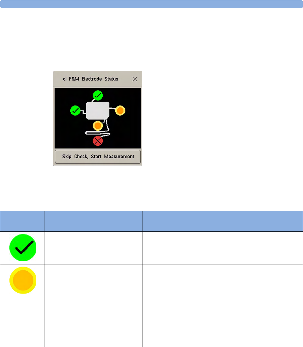
4 Cableless Monitoring
103
At the Monitor
After you have placed the CL F&M Pod on the electrode patch, the cl F&M Electrode Status window
opens at the monitor.
In the cl F&M Electrode Status window, the electrodes and their skin contact status are shown. The skin
contact status indicates, whether the skin preparation at each electrode site was successful.
1There are three methods to reopen a closed cl F&M Electrode Status window. Select:
–The
clF&M Status SmartKey (configurable)
–cl F&M Status in the setup menu of one of the CL F&M parameters (for example, Setup aFHR1)
–cl F&M Status from the Main Setup menu
Electrode
Status
Description What to Do
The skin contact status is good. When a good skin contact status is indicated for all five
electrodes, the cl F&M Electrode Status window closes, and the
measurement starts automatically.
Further skin preparation may be
required.
1Carefully remove the electrode from the skin.
2Dry the skin.
3Repeat the skin preparation procedure.
4If the contact status cannot be improved, you can choose
to skip the electrode status check by selecting the Skip
Check, Start Measurement button in the cl F&M Electrode
Status window. Measurement accuracy should not be
affected, but fetal heart rate detection may be less
sensitive.
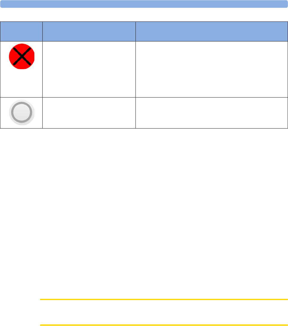
4 Cableless Monitoring
104
NOTE
If you have to repeat the skin preparation, or fix a loose electrode, ensure that enough wet gel remains
in the conductive middle of the electrode during the reapplication of the electrode. Add additional
fixation (any type of medical grade tape) to the pad in case the adhesive is compromised.
• If you cannot get a good measurement signal quality, use an alternative monitoring method.
• The electrode patch can remain applied for up to 48 hours. Remove the electrode patch, if there
are signs of skin irritation.
• If you have to replace an electrode patch:
– Gently remove the electrode patch from the abdomen of the patient.
– Wipe the abdomen dry thoroughly.
– Apply a new patch over exactly the same location. In this case, no further skin preparation is
required.
• Monitoring with the CL F&M Pod and electrode patch can continue when the patient takes a
shower. However, ensure that the CL F&M Pod remains on the electrode patch all the time, to
keep the contacts of the electrode patch dry. The achievable maximum wireless operating range
may be compromised when monitoring under a shower.
• The CL Fetal & Maternal Pod is not intended for underwater monitoring, for example in a
bathtub.
CAUTION
Do not reuse a patch on another patient due to the risk of cross contamination.
Further skin preparation is required. 1Carefully remove the electrode from the skin.
2Dry the skin.
3Repeat the skin preparation procedure.
4It is not recommended to skip the electrode status check,
if bad skin contact quality is persistently indicated for one
or more electrodes.
Electrode status is unknown. This status may be shown temporarily, or in case of a patch
malfunction, combined with an INOP message.
Electrode
Status
Description What to Do

4 Cableless Monitoring
105
After Monitoring
1After monitoring is done, remove the CL F&M Pod from the electrode patch.
2Clean and disinfect the CL F&M Pod, see “Care and Cleaning” on page 261.
3Dock the CL F&M Pod back at the base station.
4Gently remove the electrode patch and the electrodes from the abdomen of the patient.
5Dispose of the electrode patch.
6Remove the residuals of the adhesive from the patient's skin.
CL Wide Range Pod
The CL Wide Range Pod extends the signal range for the cableless measurement devices worn by the
ambulating patient.
1Assign the CL Wide Range Pod at the base station as described in “CL Pod Assignment” on
page 99.
2Activate the CL Wide Range Pod by taking it off the base station.
The CL Wide Range Pod connects itself over WLAN and LAN with the fetal monitor. As soon as
the connection to the monitor is established, the CL Wide Range Pod takes over from the base
station, and sends the signals from the cableless devices to the monitor. The connection status of
the CL Wide Range Pod is shown on the monitor, see “Cableless Status Indication” on page 95.
3Hand the CL Wide Range Pod to the patient to carry with her, or optionally wearing it using the
Mobile CL Transmitter Cradle (989803168881). The CL Wide Range Pod should be worn with its
rear side facing the body.
CL Wide Range Pod carried in hand, or CL Wide Range Pod worn with the belt clip (supporting
loop and belt clip part of the optional Mobile CL Transmitter Cradle).
4While the CL Wide Range Pod is active, cableless devices can still be assigned or unassigned at the
base station dynamically to the patient. To hand the signal transfer back from the CL Wide Range
Pod to the base station, redock the CL Wide Range Pod at the base station.

4 Cableless Monitoring
106
Battery Lifetime Management
The lifetime of a Lithium Ion battery depends on the frequency and duration of use.
CL Transducers
Battery replacement is recommended after 500 charge-discharge cycles, or if the battery is older than
4 years whatever is reached first. If the battery of a cableless transducer has aged and an exchange of
the battery is highly recommended, a prompt message is displayed at the fetal monitor for ca.
60 seconds. The prompt is repeated whenever the Tele Info window is opened until the battery is
replaced. The CL transducer battery allows for 10 hours of continuous operation.
Depending on the transducer type the following messages are displayed:
cl US battery has aged. Replacement strongly recommended
cl Toco battery has aged. Replacement strongly recommended
cl ECG/IUP batt has aged. Replacement strongly recommended
If you are getting this message, contact your service personnel so they can replace the CL transducer's
battery.
CL F&M Pod
Pod replacement is recommended after 500 charge-discharge cycles, or if the battery is older than
4 years whatever is reached first. If the battery of a CL F&M Pod has aged and an exchange of the Pod
is highly recommended, a prompt message is displayed at the fetal monitor for ca. 60 seconds. The
prompt is repeated whenever the Tele Info window is opened. The CL F&M battery allows for 16
hours of continuous operation.
The following message is displayed:
cl F&M battery has aged. Replacement strongly recommended
If you are getting this message, contact your service personnel so they can replace the CL F&M Pod.
CL Wide Range Pod
Battery replacement is recommended after 500 charge-discharge cycles, or if the battery is older than
4 years whatever is reached first. If the battery of a CL Wide Range Pod has aged and an exchange of
the battery is highly recommended, a prompt message is displayed at the fetal monitor for ca.
60 seconds. The prompt is repeated whenever the Tele Info window is opened until the battery is
replaced. The CL Wide Range Pod battery allows for 4 hours of continuous operation
The following message is displayed:
cl WRP battery has aged. Replacement strongly recommended
CL NBP and CL SpO2 Pods
For battery charge-discharge cycles specification of the IntelliVue CL Pods (NBP and SpO2), refer to
the Service Guide of the Cableless Measurements.
Charge Cycle
The age of a lithium ion battery begins at the date of manufacture. The lithium batteries are designed
for frequent recharging. A complete charging cycle is only reached and counted, when all recharging
periods equal a 100% charge.

4 Cableless Monitoring
107
The date of manufacture and number of charge-discharge cycles can be printed out in a battery report.
Patient Transport Within the Hospital
During transport, the patient wearing the CL transducers can be transferred from one fetal monitor to
another fetal monitor.
1To stop monitoring, discharge the patient at the fetal monitor. Do not switch the CL base station
to Standby.
Note: If you switch the CL base station to Standby after the discharge, the CL transducers only
hold the assignment to the CL base station for 1 minute.
2Disconnect the CL base station from the fetal monitor.
3The CL transducers hold the assignment to the CL base station for 30 minutes. Transport the
patient wearing the CL transducers with the disconnected CL base station to another fetal
monitor.
4Connect the CL base station to the other fetal monitor. The fetal monitors need to have the same
software revisions, and the correct time and date settings.
5Manually admit the patient to the fetal monitor, unless the patient is transferred to the new fetal
monitor with the OB TraceVue/IntelliSpace Perinatal system.
6Resume monitoring. Once the base station and the transducer are connected and assigned to the
new monitor, the previous monitor can be switched off or to Standby.

4 Cableless Monitoring
108
Underwater Monitoring
Only the battery-operated CL transducers of the Avalon CL and Avalon CTS systems can be used to
monitor under water. You can use them to monitor patients in a bathtub or shower. This does not
apply to the IntelliVue CL SpO2, CL NBP, and the CL Wide Range Pod, do not immerse the CL Pods
into water.
The CL F&M Pod can be worn within the shower, if the Pod is securely placed on the electrode patch,
so that the contacts cannot get wet. Radio transmission range of the CL F&M Pod may be reduced
under a shower.
Cableless transmission distances are shorter when monitoring under water. A metal bathtub is likely to
further reduce the operating range.
WARNING
Never immerse the base station in liquid. You must protect it against water sprays or splashes. Place
the base station where there is no chance of contact with water, or falling into water or other liquids.
CAUTION
Avoid the use of pulsating water jets in the bath or shower while monitoring, as these can be
misinterpreted as an incorrect (or totally artificial) heart rate.
Toco Baseline drift: When using transducers under warm water, the temperature increase causes a
significant baseline change due to internal pressure increase. The depth under water at which the Toco
transducer is used also has an effect on the Toco baseline, as the water pressure increases with depth.
After immersion, allow one to two minutes for the pressure to stabilize, then adjust the Toco baseline
(between contractions), and check it frequently.
When using the transducers underwater, the radio transmission range is reduced, and signal loss may
occur.
Water-proof belts like M1562B are recommended for the cableless transducers when monitoring in
water.
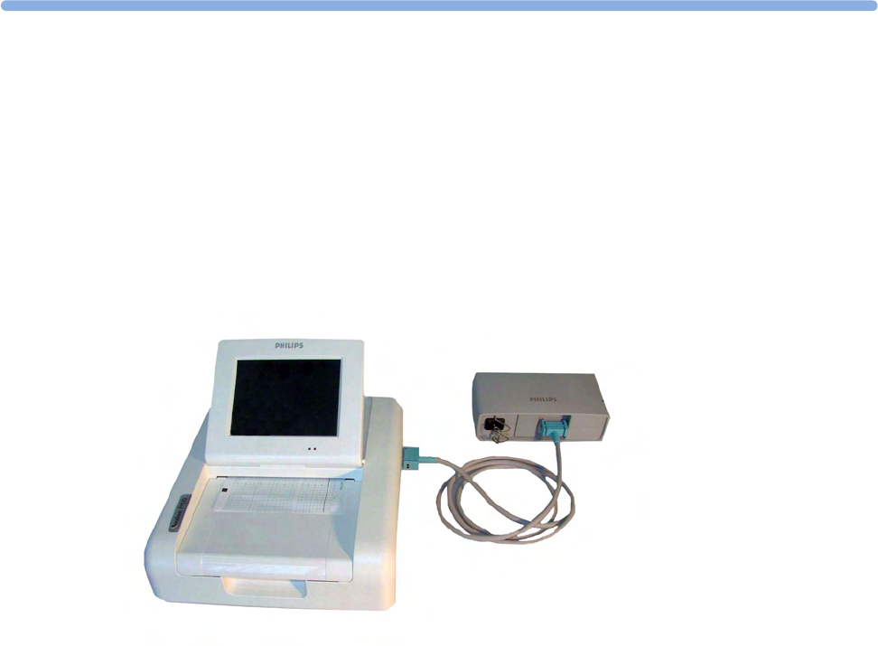
5
109
5FM20/30 Battery Option
You can switch between battery-powered and mains-powered (AC) operation without interrupting
monitoring.
The monitor is connected to the AC mains power via the external power supply.
NOTE
The battery option is not available for the FM40/FM50.
External Power Supply M8023A
The external power supply M8023A (option #E25) allows you to operate the fetal monitor from an
AC (alternating current) power source of 100 V to 240 V (±10%) and 50/60 Hz (±5%). If this option
is used, then the M8023A (option #E25) power supply is included for FM20/30.
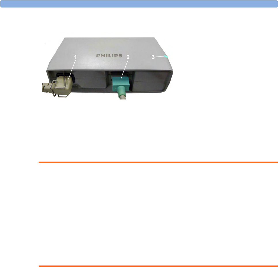
5 FM20/30 Battery Option
110
WARNING
• Always use the supplied power cord with the earthed mains plug to connect the external power
supply M8023A (option #E25) to an earthed AC mains socket. Never adapt the mains plug from
the power supply to fit an unearthed AC mains socket.
• Do not use AC mains extension cords or multiple portable socket-outlets. If a multiple portable
socket-outlet without an approved isolation transformer is used, the interruption of its protective
earthing may result in enclosure leakage currents equal to the sum of the individual earth leakage
currents, so exceeding allowable limits.
• Do not connect any devices that are not supported as part of a system.
• Any non-medical device placed and operated in the patient’s vicinity must be powered with an
approved isolation transformer that ensures mechanical fixing of the power cords and covering of
any unused power outlets.
Using Batteries
The Lithium Ion batteries used in your monitor store a large amount of energy in a small package. This
allows reliable battery-operated monitoring, but also requires care in use and handling of the batteries.
Follow the instructions in this chapter and see the Service Guide for further details.
Battery Power Indicators
The battery LED and battery status information on the main screen, in combination with INOP
messages and prompts, help you keep track of the battery power status. The indicators always show
the remaining capacity in relation to the battery's actual maximum capacity, which may lessen as the
battery ages. You can see the actual capacity in the Battery Status window.
1AC power cord, connected to AC mains socket
2Measurement Link (MSL) cable, supplies the power to the monitor for operation and for battery
charging
3Power-on LED, the green light is on when the external power supply is connected to the AC
mains
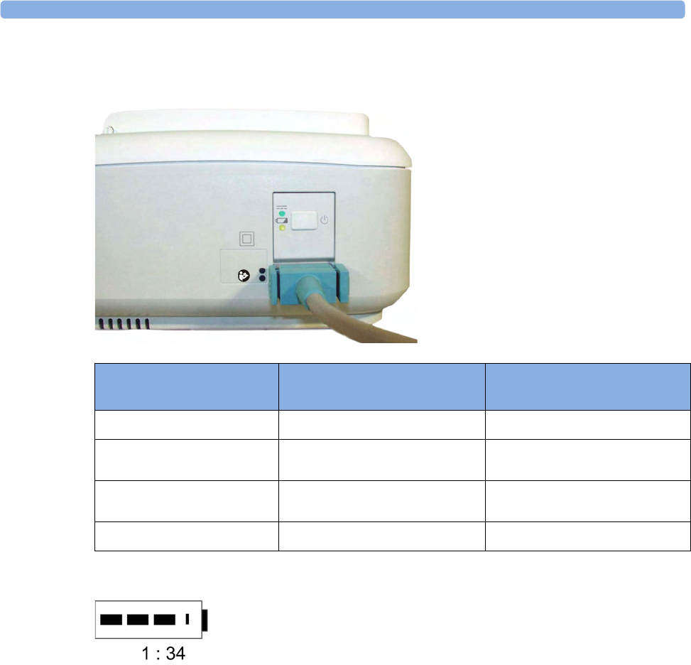
5 FM20/30 Battery Option
111
Battery LED
The possible battery LED status on the right side of the monitor is described in the table below.
Battery Status on the Main Screen
Battery status information is permanently displayed on all screens. It shows the status of the battery,
with the battery power remaining, with an estimate of the monitoring time this represents.
Battery power gauge: This shows the remaining battery power. It is divided into sections, each
representing 20% of the total power. If three sections are filled, as in this example, this indicates that
60% battery power remains. If no data is available from the battery, a question mark is shown in the
gauge.
Monitoring Time Available: Below the battery power gauge a time is displayed. This is the estimated
monitoring time available with the current battery power. Note that this time fluctuates depending on
the system load (the display brightness, the recorder configuration, and how many measurements you
carry out).
Battery LED Colors If the monitor is connected to
mains power, this means
If the monitor is running on
battery power, this means
Green Battery power is >90%
Yellow Battery charging (battery power
< 90%)
Red, flashing Less than 10 minutes power
remaining
Red, flashes intermittently Battery or charger malfunction Battery malfunction
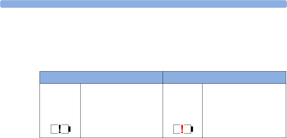
5 FM20/30 Battery Option
112
Battery malfunction symbols: Normal battery function is indicated by the battery power gauge,
together with the remaining operating time, on the main screen. You are informed of problems or
changes in the status of the battery by the battery status/malfunction indicator. This consists of a blank
battery gauge containing a "!" symbol. If the symbol is red, this indicates a critical situation. You can
check the specific cause of the problem by looking at the symbol(s) displayed in the Battery Status
window.
Battery Status Window
1To access the Battery Status window and its associated pop-up keys, select the battery status
information on the screen, or select Main Setup, Battery.
–Capacity, remaining tells you how much power is left in the battery.
–Capacity, fullCharge tells you how much power the battery can hold when fully charged.
–TimeToEmpty tells you approximately how long you can continue to use the monitor without
an AC connection. The time span fluctuates depending on the system load (the display
brightness and how many measurements you carry out), and the remaining capacity of the
battery.
–TimeToFull is shown in place of TimeToEmpty if the monitor is connected to a power supply,
and tells you how much time is left until the battery is charged to 90%. If >10 hr is shown
here, the battery may not charge completely when the monitor is in use.
Battery status/malfunction symbols: If a problem is detected with the battery, an INOP may be
issued, and the following symbols are displayed in the Battery Status window, where they may be
accompanied by a status message providing more details.
Battery Status Indicator Battery Malfunction Indicator
Alternates with the battery gauge
on the main screen.
Check in the Battery Status
window to see which status
symbol is displayed to identify
the cause.
The red exclamation mark
flashes. Critical battery situation
or malfunction. Check in the
Battery Status window to see
which malfunction indicator is
displayed, or refer to the INOP,
to identify the cause.
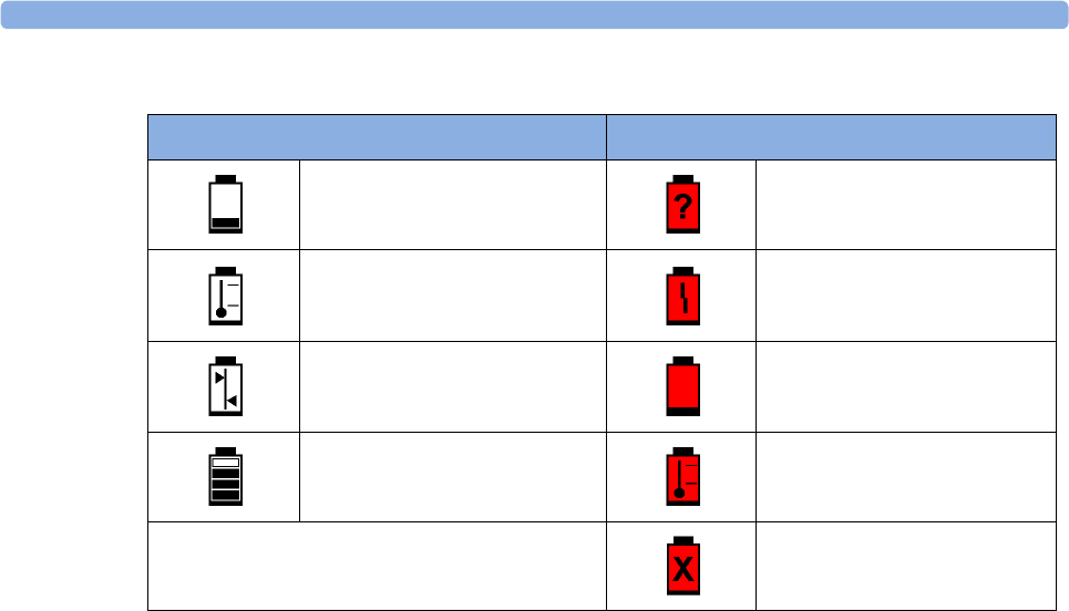
5 FM20/30 Battery Option
113
Symbols indicating critical situations are colored red.
Checking Battery Charge
To check the charge status of a battery, refer to the battery power gauge on the screen, or open the
Battery Status window.
When Battery Lifetime is Expired
When the battery is aged, either after 3 years from manufacturing date or after 500 charge-discharge
cycles, it is recommended to replace the battery. To remind you of this, a message will appear in the
Battery Status window. This message will only be displayed at the appropriate time when the date and
time on the monitor is correct.
Optimizing Battery Performance
The performance of rechargeable batteries may deteriorate over time. Battery maintenance as
recommended here can help to slow down this process.
Display Brightness Setting
1In the Main Setup menu, select User Interface, Brightness, then Optimum. This selects a level of
brightness suitable for most monitoring locations that uses less battery power than brighter
settings.
2Ensure that the current level of brightness is suitable for your monitoring location.
Battery Status Symbols Battery Malfunction Symbols
Battery is empty (Red) incompatible battery
Battery not charging as the
temperature is above or below
the specified range
(Red) battery malfunction
Battery requires maintenance (Red) battery has no power left
Charging stopped to protect the
battery
(Red) battery temperature too
high
(Red) battery is missing, insert
battery

5 FM20/30 Battery Option
114
Charging the Battery
To charge the battery:
1Connect the monitor to the external power supply (M8023A).
2Charge the battery until it is full, the battery LED is green, and the battery power gauge is filled.
During high load of the monitor (usage of multiple measurements) the battery may not charge. To
remedy this:
• reduce the load by removing measurements
• reduce the screen brightness or stop the recorder
Internal temperature conditions can also cause the battery to not charge. This is necessary to protect
the battery from damage and does not indicate a malfunction. Keep the monitor at room temperature
and move it away from heat sources or out of direct sunlight. The battery will resume charging when
the temperature is within range again. The battery will charge more quickly if the monitor is switched
off.
Conditioning the Battery
You must condition the battery when the "battery requires maintenance" symbol shows on the screen.
Do not interrupt the charge or discharge cycle during conditioning.
CAUTION
Condition the battery with a monitor not currently in use. The monitor switches off automatically
when there is no battery power left.
To condition the battery:
1Charge the battery until it is completely full. Open the Battery Status window and check that the
Batt fully charged message is displayed.
2Disconnect the monitor from mains power, and let the monitor run until there is no battery power
left and the monitor switches itself off.
3Reconnect the monitor to mains power and charge the battery until it is full for use or charge to
50% for storage.

5 FM20/30 Battery Option
115
Battery Safety Information
WARNING
Use only Philips batteries part number M4605A. Use of a different battery may present a risk of fire
or explosion.
Do not open batteries, or dispose of them in fire, or cause them to short circuit. They may ignite,
explode, leak, or heat up, causing personal injury.
If battery leakage should occur, avoid contact with skin. Refer to qualified and authorized service
personnel.
Dispose of used batteries promptly and in an environmentally responsible manner. Do not dispose
of the battery in normal waste containers. Consult your hospital administrator to find out about local
arrangements. Do not expose batteries to liquids.
Do not crush, drop, or puncture batteries - mechanical abuse can lead to internal damage and internal
short circuits which may not be visible externally.
If a battery has been dropped or banged against a hard surface, whether damage is visible externally or
not:
• discontinue use
• dispose of the battery in accordance with the disposal instructions above.
Keep batteries out of the reach of children.
CAUTION
Do not disassemble, heat above 100°C (212°F) or incinerate the batteries, to avoid the risk of fire and
burns. Keep batteries out of the reach of children and in their original package until you are ready to
use them.
If battery leakage should occur, use caution in removing the battery. Avoid contact with skin. Refer to
qualified and authorized service personnel.
Do not install or use pre-damaged batteries.
Storing the Battery
WARNING
Remove the battery from the monitor when it is not used for a longer period of time, to avoid
potential damage caused by battery leakage.
Batteries should be charged to a maximum of 50% for storage.
The battery will discharge over time if it is stored inside the monitor without AC power connection.
The reported values for "remaining capacity" and "runtime" will become less accurate when the battery
is stored in this way for a longer period of time (that is, several weeks).

5 FM20/30 Battery Option
116
Cableless Monitoring with FM20/30 Battery Option
The CL Pods can be used with the FM20/30 with battery option #E25. The CL Pods can be assigned
and activated, but will not be charged. The only exception to this is the CL F&M Pod, which can also
be charged.
The charging time of the CL transducers can take up to 6 hours if they are charged from an FM20/30
with battery option.
If you charge the CL transducers at an FM20/30 with battery option, be sure to remove all wired
transducers from the fetal monitor. Leaving them connected to the fetal monitor can cause the
CL transducers not to charge at all.
Patient Transport Within the Hospital
The FM20 and FM30 fetal monitor with battery option offer the possibility of continuous monitoring
of a patient, while she is transported within the hospital.
1Unplug the MSL connector at the fetal monitor. Or, in case an external power supply is mounted
on a rollstand, unplug it from the AC Mains.
The fetal monitor is now operating on battery power.
2Move the patient with the fetal monitor (on a cart) to the new location.
3Reconnect the MSL connector at the fetal monitor or the external power supply to the AC Mains.

6
117
6Alarms
The alarm information here applies to all measurements. Measurement-specific alarm information is
contained in the sections on individual measurements.
The fetal monitor has two different types of alarm: patient alarms and INOPs.
Patient Alarms
Patient alarms are red and yellow alarms. A red alarm indicates high priority, such as a potentially life
threatening situation (for example, SpO2 below the desaturation alarm limit). A yellow alarm indicates
a lower priority alarm (for example, a fetal heart rate alarm limit violation).
INOPs
INOPs are technical alarms. They indicate that the monitor cannot measure and therefore not detect
critical conditions reliably. If an INOP interrupts monitoring and alarm detection (for example, MECG
Leads Off), the monitor places a question mark in place of the measurement numeric and sounds an
audible tone. INOPs without this tone indicate that there may be a problem with the reliability of the
data, but that monitoring is not interrupted.
INOPs are cyan by default. The following INOPs can also be configured as red or yellow INOPs to
provide a severity indication:
•ECG Leads Off
•Battery Empty (FM20/30, CL devices)
•Cuff Overpress
•Cuff NotDeflated
•No Pulse
Alarm Delays
There is a delay between a physiological event at the measurement site and the corresponding alarm
indication at the monitor. This delay has two components:
•The general measurement delay time is the time between the occurrence of the
physiological event and when this event is represented by the displayed numerical values.
This delay depends on the algorithmic processing and on the measurement dependent averaging
time.

6 Alarms
118
•The time between the displayed numerical values exceeding an alarm limit and the alarm
indication on the monitor. This delay is the sum of the alarm delay configured for the specific
measurement plus the system alarm delay. The system alarm delay is the processing time the
system needs for any alarm on the monitor to be indicated after the measurement has triggered the
alarm. See the performance specifications in “Specifications and Standards Compliance” on
page 287 for the system alarm delay specification.
Multiple Alarms
If more than one alarm is active, the alarm messages are shown in the alarm status area in succession.
An arrow symbol next to the alarm message informs you that more than one message is active.
The monitor sounds an audible indicator for the highest priority alarm. If more than one alarm
condition is active in the same measurement, the monitor announces the most severe alarm condition
first.
WARNING
Alarm systems of the monitor and those of the connected obstetrical information and surveillance
system are independent and not synchronized.
Alarming is only available at the Avalon fetal monitor, not at the Cableless Measurement Devices, see
the Instructions for Use for the IntelliVue Cableless Measurements.
If configured so, SpO₂ No Pulse will only be displayed in yellow or red (instead of cyan), when no other
Pulse source is valid and is displayed instead of the Pulse from SpO2.
Alarm Mode
You can configure the alarm mode for your fetal monitor. There are two possible modes:
•All: alarms and INOPs are enabled, with all audible and visual indicators active.
•INOP only: only INOPs are enabled, with audible and visual indication active.
WARNING
In INOP only mode, no fetal/maternal patient alarms are enabled or indicated.
The alarm status area for yellow and red alarms shows the INOP only indication in conjunction with the
"Alarms Off" symbol. No individual measurement alarm limits or alarm off symbols are displayed. No
fetal/maternal patient alarm settings are available in the setup menus.
Nurse Call Systems
If configured to do so, red, yellow, and cyan alarms are indicated on a nurse call system which is
connected to the optional nurse call relay.

6 Alarms
119
Visual Alarm Indicators
Alarm message: An alarm message appears in the alarm status area on the second line at the top of
the screen indicating the source of the alarm. If more than one measurement is in an alarm condition,
the message changes every two seconds, and has an arrow at the side. The background color of the
alarm message matches the alarm priority: red for red alarms and red INOPs, yellow for yellow alarms
and yellow INOPs, and cyan for INOPs. The asterisk symbols (*) beside the alarm message match the
alarm priority: *** for red alarms, and ** for yellow alarms. INOPs are displayed without asterisks, but
a red INOP has !!! three exclamation marks, and a yellow INOP has !! two exclamation marks before it.
Depending on how your monitor is configured, it may display alarm limit violation messages:
• in text form, for example ** FHR1 Low or
• in numeric form, for example **FHR1 94<110, where the second number shows the currently set
alarm limit, and the first number shows the value at which that alarm limit was violated by the
widest margin.
Flashing numeric: The numeric of the measurement in alarm flashes.
Bright alarm limits: If the alarm was triggered by an alarm limit violation, the corresponding alarm
limit on the monitor screen is shown more brightly.
Audible Alarm Indicators
The audible alarm indicators configured for your fetal monitor depend on which alarm standard
applies in your hospital. Audible alarm indicator patterns are repeated until you acknowledge the alarm
by switching it off or pausing it, or until the alarm condition ceases (if audible alarm indication is set to
non-latching).
WARNING
Do not rely exclusively on the audible alarm system for fetal monitoring. Adjustment of alarm volume
to a low level or off during monitoring may result in a dangerous situation. Remember that the most
reliable method of fetal monitoring combines close personal surveillance with correct operation of
monitoring equipment.
Alarm Tone Configuration
The audible alarm indicators of your monitor are configurable. In the monitor's Configuration Mode,
you can:
• increase the alarm volume of unacknowledged alarms at regular intervals
• change the interval between alarm sounds (ISO/IEC Standard alarms only)
• change the base volume of the red and yellow alarm tones and the INOP tones
• change the alarm sound to suit the different alarm standards valid in different countries
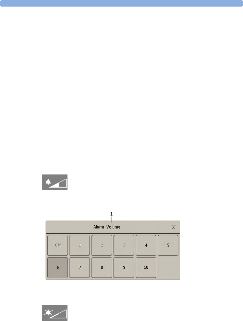
6 Alarms
120
Standard Philips Alarms
• Red alarms and red INOPs: a high pitched sound is repeated once a second.
• Two-star yellow alarms and yellow INOPs: a lower pitched sound is repeated every two seconds.
• One-star yellow alarms (short yellow alarms): the audible indicator is the same as for yellow
alarms, but of shorter duration.
• Standard INOPs: an INOP tone is repeated every two seconds.
ISO/IEC Standard Audible Alarms
• Red alarms and red INOPs: a high pitched tone is repeated five times, followed by a configurable
pause.
• Two-star yellow alarms and yellow INOPs: a lower pitched tone is repeated three times, followed
by a configurable pause.
• One-star yellow alarms (short yellow alarms): the audible indicator is the same as for yellow
alarms, but of shorter duration.
• Standard INOPs: a lower pitched tone is repeated twice, followed by a pause.
Changing the Alarm Tone Volume
The alarm volume symbol at the top right of the monitor screen gives you an indication of the current
volume. To change the volume:
1Select the volume symbol.
2The volume scale pops up.
3Select the required volume from the volume scale.
When the alarm volume is set to zero (Off), the alarm volume symbol shows this symbol:
If you switch the alarm volume off, you will not get any audible indication of alarm conditions.
1 Alarm Volume
6 Alarms
121
Minimum Volume for Severe Yellow or Red INOPs
Severe yellow or red INOPs require action to ensure the well-being of the patient. Therefore the
minimum volume for the INOP tone is set to at least alarm volume 8, irrespective of the current alarm
volume setting. The INOP tone will sound even if the monitor alarm volume is set to zero.
The severe INOPs for which this applies are:
Power Loss Tone
FM20/30 with
Battery
Option,
FM40/50
When power is lost - no power is available from the AC power source or from the battery - a beeper
will sound. The tone can be silenced by pressing the On/Standby button.
Acknowledging Alarms
To acknowledge all active alarms and INOPs, select the Silence key. This switches off the audible alarm
indicators.
• A checkmark beside the alarm message indicates that the alarm has been acknowledged.
• If the condition that triggered the alarm is still present after the alarm has been acknowledged, the
alarm message stays on the screen with a checkmark symbol beside it.
• If the alarm condition is no longer present, all alarm indicators stop and the alarm is reset.
• Switching off the alarms for the measurement in alarm, or switching off the measurement itself,
also stops alarm indication.
Acknowledging Disconnect INOPs
Acknowledging an INOP that results from a disconnected transducer, switches off the associated
measurement.
INOP Factory Default INOP tone
Battery Empty cyan severe (fetal monitor with battery
option)
Battery Empty cyan severe (CL transducers and Pods)
Cuff Overpress cyan severe
Cuff NotDeflated cyan severe

6 Alarms
122
Alarm Reminder
If Alarm Reminder is configured on for your monitor, you will get an audible reminder of alarm
conditions that remain active after you have acknowledged the alarm. This reminder may take the form
of a repetition of the alarm tone for a limited time, or an unlimited repetition of the alarm tone (this is
the same as a new alarm). Alarm Reminder is available only for yellow and red alarms and INOPs and
not for standard cyan INOPs.
In Configuration Mode, you can set the interval between silencing the alarm and sounding the
reminder tone to one, two, or three minutes.
Pausing or Switching Off Alarms
If you want to temporarily prevent alarms from sounding, for example while you are moving a patient,
you can pause alarms. Depending on your fetal monitor configuration, alarms are paused for one, two,
or three minutes, or infinitely.
To view the alarm pause setting chosen for your unit:
1Select Main Setup, Alarms, Alarm Settings.
2Check the Alarms Off setting.
This setting can be changed in Configuration Mode.
There are some settings made in Configuration Mode that can affect the availability of the pause
alarms functionality.
•The
Pause Alarms/Alarms Off SmartKey can be removed from the screen to avoid unintentional
switching off of alarms. In this case you can only pause alarms or switch alarms off permanently in
the Alarms menu, under Main Setup.
•The
Pause Alarms/Alarms Off SmartKey can be configured to pause or switch off red and yellow
alarms, yellow alarms only, or not to function at all. If it is configured not to function, you cannot
pause alarms or switch alarms off permanently at all.
When the alarms off priority is set to Yellow Only, the Pause Alarms/Alarms Off key becomes the Pause
Yellow/Yellow Al. Off.
To Pause All Alarms
If you have configured alarms to be paused for one, two, or three minutes, the SmartKey is labeled
Pause Alarms.
Select the Pause Alarms SmartKey to pause all alarms.
Or
1Select Main Setup.
2Select Alarms.
3Select Pause Alarms.
6 Alarms
123
To Switch All Alarms Off
You can switch alarms off permanently if your monitor is configured to allow infinite alarms pause,
and the SmartKey is labeled Alarms Off.
Select the Alarms Off SmartKey.
Or
1Select Main Setup.
2Select Alarms.
3Select Alarms Off.
While Alarms are Paused or Off
When red alarms are paused or off:
In the alarm field, the monitor displays the message Al. Paused x:yy or Alarms Off, together with the
alarms paused symbol or the alarms off symbol.
When yellow alarms are paused or off:
In the alarm field, the monitor displays the message YellowPaused x:yy or Yellow Alarms Off, together
with the alarms paused symbol or the alarms off symbol.
For red and yellow alarms:
Alarms Paused
Alarms Off
• No alarms are sounded and no alarm messages are shown.
• INOP messages are shown but no INOP tones are sounded.
The only exceptions are the INOPs Cuff NotDeflated, Cuff Overpress, and Battery Empty from the
FM20/30 monitor with battery option.
These INOPs switch all alarms back on again, so that an INOP tone can be sounded. You must
remove the INOP condition first, before you can switch off or pause the alarms again.
Restarting Paused Alarms
To manually switch on alarm indication again after a pause, select the SmartKey Pause Alarms (or
Alarms Off) again.
Alarm indication starts again automatically after the pause period expires. If the monitor is configured
to stay paused infinitely, you must select Alarms Off again to restart alarm indication.

6 Alarms
124
Extending the Alarm Pause Time
If your monitor has the function extended alarm pause enabled, you can extend the alarm pause time.
Use this to prevent alarms being indicated, for example, while you are washing a patient or carrying out
a procedure. Only extend the alarm pause time when you are sure that clinical personnel are available
to monitor the patient's condition closely.
To extend the alarm pause time to five or 10 minutes:
1Select one of the alarm fields. This calls up the Alarm Messages window.
2Select either the pop-up key PauseAl. 5 min or the pop-up key PauseAl. 10 min. Each time you
select one of these pop-up keys, the Alarm Pause Time is reset to five or 10 minutes.
To Switch Individual Measurement Alarms On or Off
This applies to alarm mode All.
1Select the measurement numeric to enter its setup menu.
2Select Alarms to switch between On and Off.
The alarms off symbol is shown beside the measurement numeric.
Alarm Limits
The alarm limits you set determine the conditions that trigger yellow and red limit alarms.
WARNING
Be aware that the monitors in your care area may each have different alarm settings, to suit different
scenarios. Always check that the alarm settings are appropriate before you start monitoring.
Viewing Individual Alarm Limits (Alarm Mode "All" Only)
You can usually see the alarm limits set for each measurement next to the measurement numeric on
the main screen.
1Alarm Limits
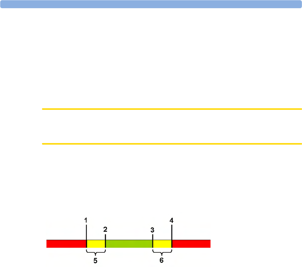
6 Alarms
125
If your monitor is not configured to show the alarm limits next to the numeric, you can see them in the
related measurement setup menu. Select the measurement numeric to enter the menu and check the
limits.
Changing Alarm Limits
To change individual measurement alarm limits using the measurement's setup menu:
1In the measurement's setup menu, select the alarm limit you want to change. This calls up a list of
available values for the alarm limit.
2Select a value from the list to adjust the alarm limit.
CAUTION
Set the alarm limits to a meaningful value for the individual patient. Setting the alarm limits to a too
high or too low value may render the alarm function useless.
Extreme Alarm Limits for Heart Rate and Maternal Pulse
The extreme rate alarms, Extreme Tachy and Extreme Brady, generated by the active alarm source,
either HR or Pulse, are set in Configuration Mode by adding a set value (the Δ value) to the high and
low alarm limits.
You need to know which value has been configured for your monitor. Changing the high and low
alarm limits automatically changes the extreme alarm limits within the allowed range.
To see the extreme rate alarms set for your monitor, in the Setup ECG menu, see the menu items Δ
ExtrTachy and Δ ExtrBrady.
1Extreme Brady Limit
2Low Limit
3High Limit
4Extreme Tachy Limit
5Δ Extreme Brady
6Δ Extreme Tachy
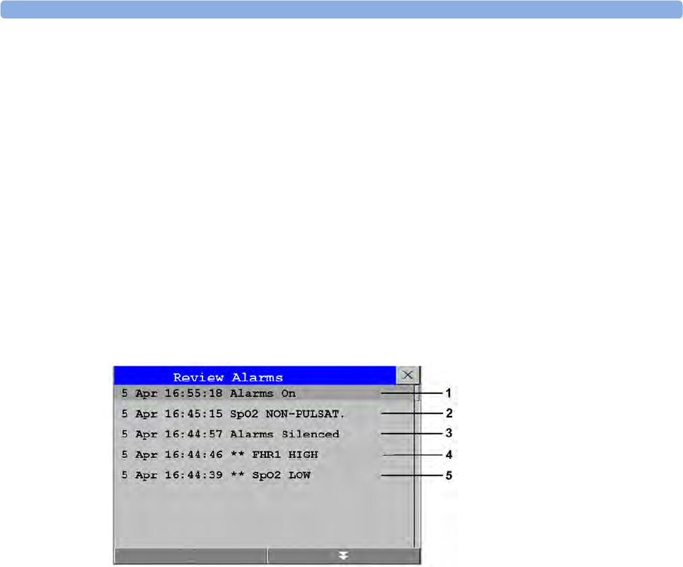
6 Alarms
126
Reviewing Alarms
To review the currently active alarms and INOPs, select any of the alarm status areas on the fetal
monitor screen. The Alarm Messages window pops up. All alarms and INOPs are erased from the
monitor's alarm history when you discharge a patient, or if you leave the Demonstration Mode.
Alarm Messages Window
The Alarm Messages window shows all the currently active alarms and INOPs in chronological order,
beginning at the top with the most recent. INOPs are shown on the left hand side, and alarms are
shown on the right hand side. Any active red alarms are shown first, followed by yellow alarms.
Acknowledged alarms or INOPs are shown with the checkmark symbol.
The Alarm Messages window pop-up keys appear when the window is opened. Selecting the Review
Alarms pop-up key opens the Review Alarms window.
Review Alarms Window
The Review Alarms window contains a list of up to 300 of the most recent alarms and INOPs with date
and time information. If configured to do so, each alarm is shown with the alarm limit active when the
alarm was triggered and the maximum value measured beyond this limit. The Review Alarms window
also shows any changes made to the Alarms On/Off or Alarms Silenced status. Only the main alarms
On/Off transitions are logged in the alarm history, and On/Off alarm transitions for individual
measurements are not logged.
The information in the Review Alarms window is deleted when a patient is discharged.
The Review Alarms window pop-up keys appear when the window is opened. Selecting the Active
Alarms pop-up key opens the Alarm Messages window.
Latching Alarms
The alarm latching setting for your monitor defines how the alarm indicators behave when you do not
acknowledge them. When alarms are set to non-latching, their indicators end when the alarm condition
ends. Switching alarm latching on means that visual and/or audible alarm indications are still displayed
or announced by the monitor after the alarm condition ends. The indication lasts until you
acknowledge the alarm.
1Alarms On
2SpO₂ No Pulse
3Alarms Silenced
4** FHR1 High
5** SpO₂ Low

6 Alarms
127
Viewing the Alarm Latching Settings
To see the alarm latching setting for your monitor:
1In the monitor's Main Setup menu, select Alarms.
2Select Alarm Settings, and see the Visual Latching and Audible Latching settings.
This setting can be changed in Configuration Mode. You should be aware of the settings chosen for
your unit. There are three possible choices each for visual and audible latching: Red & Yellow, Red Only,
and Off. The audible latching configuration can never be configured to a higher level than that
configured for the visual latching. In other words, the audible latching setting is always the same level,
or lower, than the visual latching setting. For example, if visual latching is configured to Red Only, then
audible latching can only be set to Red Only or Off. The following table shows the possible
combinations for latching settings:
Alarm Latching Behavior
All INOPs except the "unplugged" INOPs are non-latching.
Possible Combinations for Alarm Latching Settings
Visual Latching Setting Audible Latching Setting
Red & Yellow Red & Yellow
Red & Yellow Red Only
Red & Yellow Off
Red Only Red Only
Red Only Off
Off Off
Alarm Condition Red and Yellow Measurement Alarms
Acknowledgment Presence Non-latching alarms Visual and audible
latching
Visual latching,
audible non-latching
Alarm has not been
acknowledged
Alarm
condition still
present
Alarm tone on
Alarm message
Flashing numerics
Alarm tone on
Alarm message
Flashing numerics
Alarm tone on
Alarm message
Flashing numerics
Alarm
condition no
longer present
All audible and visual
alarm indicators
automatically stop
Alarm tone on
Alarm message
Flashing numerics
Audible alarm
indicators automatically
stop
Alarm message
Flashing numerics
Alarm has been
acknowledged
Alarm
condition still
present
Alarm tone off
Audible alarm
reminder (if
configured)
Alarm message
Flashing numerics
Alarm tone off
Audible alarm reminder
(if configured)
Alarm message
Flashing numerics
Alarm tone off
Audible alarm reminder
(if configured)
Alarm message
Flashing numerics
Alarm
condition no
longer present
Audible and visual
alarm indicators
automatically stop
Audible and visual
alarm indicators
automatically stop
Audible and visual
alarm indicators
automatically stop

6 Alarms
128
Testing Alarms
When you switch the fetal monitor on, a self test is started. You should hear a single tone. This
indicates that the audible alarm indicators are functioning correctly. For further testing of individual
measurement alarms, perform the measurement on yourself (for example SpO2 or NBP) or use a
simulator. Adjust alarm limits and check that appropriate alarm behavior is observed.
To test the functioning of visible and audible alarms, do the following:
1Enable the alarm (Alarm Mode needs to be set to All, see the Configuration Guide).
2Set the alarm limits.
3Measure or simulate the parameter that is out of range, or signal loss.
4Verify that the visible and audible alarms are working.
As an example, to test the FHR alarms:
1Connect the US transducer to a fetal sensor socket.
2Enable the FHR alarming (see “Turning Alarms On or Off” on page 197).
Set the high alarm limit and delay to 150 bpm and 60 seconds respectively, and the low alarm limit and
delay to 110 bpm and 60 seconds respectively (see “Changing Alarm Limits” on page 197).
1Generate a fetal heart rate of approximately 180 bpm (3 beats per second) for more than one
minute.
2Verify the functioning of the visible and audible alarms.
Alarm Behavior at Power On
If the monitor is switched off for longer than one minute and then switched on again, or after a loss of
power lasting longer than one minute, the monitor can be configured to restore either the alarm
settings from the monitor's User Defaults, or the most recently used alarm settings. When a patient is
discharged, the User Defaults of the monitor are always restored independent of the setting. After any
of these situations, ensure that the alarm settings are appropriate for your patient. If power is lost for
less than one minute, the alarm settings prior to the power loss are restored.
•If
AlarmsOffAtStart is enabled in Configuration Mode alarms will be initially paused or off the next
time the monitor is switched on, depending on a set of related configuration settings, see the
Configuration Guide.

7
129
7Patient Alarms and INOPs
This chapter lists alarms and technical alarms (INOPs) for the fetal monitors irrespective of their
priority.
Alarm Messages
Fetal alarms are identified by either "FHR", "dFHR", or aFHR. All other alarms without these
identifiers refer to maternal parameters. Alarm messages can be configured with the Enhanced setting
to give more information. These messages are shown additionally in the table below, with xxx for the
measured value and yyy for the alarm limit concerned.
Alarm Message From Condition Indication
** aFHR1 High
** aFHR2 High
** aFHR3 High
** aFHR1 xxx>yyy
** aFHR2 xxx>yyy
** aFHR3 xxx>yyy
FHR
(CL F&M Pod)
The fetal heart rate obtained from the
CL F&M Pod has risen above the high
alarm limit.
xxx denotes the highest measured value, and
yyy is the high alarm limit.
Numeric flashes and high
limit is highlighted, yellow
alarm message, alarm tone.
** aFHR1 Low
** aFHR2 Low
** aFHR3 Low
** aFHR1 xxx<yyy
** aFHR2 xxx<yyy
** aFHR3 xxx<yyy
FHR
(CL F&M Pod)
The fetal heart rate obtained from the
CL F&M Pod has fallen below the low
alarm limit.
xxx denotes the lowest measured value, and
yyy is the low alarm limit.
Numeric flashes and low limit
is highlighted, yellow alarm
message, alarm tone.
**aHR High
**HR xxx<yyy
HR
(CL F&M Pod)
The maternal heart rate obtained from the
CL F&M Pod has risen above the high
alarm limit.
xxx denotes the highest measured value, and
yyy is the high alarm limit.
Numeric flashes and high
limit is highlighted, yellow
alarm message, alarm tone.
**aHR Low
**HR xxx>yyy
HR
(CL F&M Pod)
The maternal heart rate obtained from the
CL F&M Pod fallen below the low alarm
limit.
xxx denotes the lowest measured value, and
yyy is the low alarm limit.
Numeric flashes and low limit
is highlighted, yellow alarm
message, alarm tone.

7 Patient Alarms and INOPs
130
*** Brady (Pulse)
***Brady/P xxx<yyy
SpO2The heart rate from the Pulse signal has
fallen below the bradycardia limit.
xxx denotes the lowest measured value; yyy
is the bradycardia limit.
Numeric flashes, red alarm
message, alarm tone.
*** Desat
*** Desat xx < yy
SpO2The SpO2 value has fallen below the
desaturation alarm limit. xx denotes the
lowest measured value, and yy is the
desaturation limit.
Numeric flashes, red alarm
message, alarm tone.
** dFHR1 High
** dFHR2 High
** dFHR3 High
**dFHR1 xxx>yyy
**dFHR2 xxx>yyy
**dFHR3 xxx>yyy
FHR (DECG) The fetal heart rate obtained from DECG
has risen above the high alarm limit.
xxx denotes the highest measured value, and
yyy is the high alarm limit.
Numeric flashes and high
limit is highlighted, yellow
alarm message, alarm tone.
** dFHR1 Low
** dFHR2 Low
** dFHR3 Low
**dFHR1 xxx<yyy
**dFHR2 xxx<yyy
**dFHR3 xxx<yyy
FHR (DECG) The fetal heart rate obtained from DECG
has fallen below the low alarm limit.
xxx denotes the lowest measured value, and
yyy is the low alarm limit.
Numeric flashes and low limit
is highlighted, yellow alarm
message, alarm tone.
*** Extreme Brady
***xBrady xxx<yyy
MECG The maternal heart rate obtained from the
maternal ECG has fallen below the extreme
bradycardia limit.
xxx denotes the lowest measured value, and
yyy is the extreme bradycardia limit.
Numeric flashes, red alarm
message, alarm tone.
*** Extreme Tachy
***xTachy xxx>yyy
MECG The maternal heart rate obtained from the
maternal ECG has risen above the extreme
tachycardia limit.
xxx denotes the highest measured value, and
yy is the extreme tachycardia limit.
Numeric flashes, red alarm
message, alarm tone.
** FHR1 High
** FHR2 High
** FHR3 High
**FHR1 xxx>yyy
**FHR2 xxx>yyy
**FHR3 xxx>yyy
FHR
(ultrasound)
The fetal heart rate obtained from
ultrasound has risen above the high alarm
limit.
xxx denotes the highest measured value, and
yyy is the high alarm limit.
Numeric flashes and high
limit is highlighted, yellow
alarm message, alarm tone.
** FHR1 Low
** FHR2 Low
** FHR3 Low
**FHR1 xxx<yyy
**FHR2 xxx<yyy
**FHR3 xxx<yyy
FHR
(ultrasound)
The fetal heart rate obtained from
ultrasound has fallen below the low alarm
limit.
xxx denotes the lowest measured value, and
yyy is the low alarm limit.
Numeric flashes and low limit
is highlighted, yellow alarm
message, alarm tone.
Alarm Message From Condition Indication

7 Patient Alarms and INOPs
131
** HR High
**HR xxx>yyy
MECG The maternal heart rate obtained from the
maternal ECG has risen above the high
alarm limit.
xxx denotes the highest measured value, and
yyy is the high alarm limit.
Numeric flashes and high
limit is highlighted, yellow
alarm message, alarm tone.
** HR Low
**HR xxx<yyy
MECG The maternal heart rate obtained from the
maternal ECG has fallen below the low
alarm limit.
xxx denotes the lowest measured value, and
yyy is the low alarm limit.
Numeric flashes and low limit
is highlighted, yellow alarm
message, alarm tone.
** <iTemp Label> High iTemp The temperature value has exceeded the
high alarm limit.
Numeric flashes and high
limit is highlighted, alarm
tone.
** <iTemp Label> Low iTemp The temperature value has dropped below
the alarm limit.
Numeric flashes and low limit
is highlighted, alarm tone.
** NBPs High
** NBPd High
** NBPm High
Noninvasive
blood pressure
The measured noninvasive blood pressure
value is above the high alarm limits s, d, or
m after the label indicates whether the
systolic, diastolic, or mean pressure has
crossed the limit.
Numeric flashes and high
limit is highlighted, yellow
alarm message, alarm tone.
** NBPs Low
** NBPd Low
** NBPm Low
Noninvasive
blood pressure
The measured noninvasive blood pressure
value is below the low alarm limits s, d, or m
after the label indicates whether the systolic,
diastolic, or mean pressure has crossed the
limit.
Numeric flashes and low limit
is highlighted, yellow alarm
message, alarm tone.
** Pulse High SpO2The pulse rate has exceeded the high alarm
limit.
Numeric flashes and high
limit is highlighted, yellow
alarm message, alarm tone.
** Pulse Low SpO2The pulse rate has dropped below the low
alarm limit.
Numeric flashes and low limit
is highlighted, yellow alarm
message, alarm tone.
** SpO₂ High SpO2The arterial oxygen saturation has exceeded
the high alarm limit.
Numeric flashes and high
limit is highlighted, yellow
alarm message, alarm tone.
** SpO₂ Low SpO2The arterial oxygen saturation has fallen
below the low alarm limit.
Numeric flashes and low limit
is highlighted, yellow alarm
message, alarm tone.
*** Tachy (Pulse)
***Tachy/P xxx>yyy
SpO2The heart rate from the Pulse signal has
exceeded the tachycardia limit.
xxx denotes the highest measured value, and
yyy is the tachycardia limit.
Numeric flashes, red alarm
message, alarm tone.
Alarm Message From Condition Indication

7 Patient Alarms and INOPs
132
Technical Alarm Messages (INOPs)
Monitor INOPs
INOP Message Indication What to do
2nd Tele Incompatible Monitor: INOP tone One of the connected base stations is not supported by
the monitor. Check software revisions.
Bus Master Incomp Monitor: INOP tone The Bus Master board or firmware is incompatible and
cannot be used with this monitor software revision.
Contact your service personnel.
Bus Master Malfunc Monitor: INOP tone There is a problem with the monitor's hardware. Contact
your service personnel.
Check Flex Texts Monitor: INOP tone If this INOP appears, check the monitor and patient
settings before you resume monitoring. If the settings are
unexpected, there may be a problem with the monitor
software. Contact your service personnel.
Check Keyboard Monitor: INOP tone Perform a visual and functional check of the keyboard.
Contact your service personnel.
Check Monitor Func Monitor: INOP tone A potential internal problem with the monitor has been
detected. Contact your service personnel.
Check Mouse Monitor: INOP tone Perform a visual and functional check of the mouse input
device. Contact your service personnel.
Check OBR Config Monitor: INOP tone OBR (OB Radio) channel configuration is invalid or
settings are not present. Check channel configuration and
hardware option.
Check Settings Monitor: INOP tone If this INOP appears, check the monitor and patient
settings before you resume monitoring. If the settings are
unexpected, there may be a problem with the monitor
software. Contact your service personnel.
Check TI Config Monitor: INOP tone If this INOP appears, the monitor can be used normally,
except for the Trace Interpretation feature. Contact your
service personnel.
Check Touch Input Monitor: Display only Perform a visual and functional check of the touch input
device. Contact your service personnel.
Coincidence
!! Coincidence
Monitor: INOP tone The fetal heart rate(s) and maternal heart rate/pulse
persistently coincide with another. (see “Cross-Channel
Verification (CCV)” on page 159). The INOP tone has a
configurable delay. The default setting is an instant INOP
tone.
Internal.Comm.Malf Monitor: INOP tone There is a problem with I2C Bus communication in the
monitor. Contact your service personnel.
NST Elapsed Monitor: INOP tone
(Message and tone only if
Setup NST Timer, Notification
is set to Alarm in
Configuration Mode).
The time has expired for the NST timer. Clearing the
timer clears the INOP.

7 Patient Alarms and INOPs
133
FM20/FM30 Battery INOPs
OBR Interference Monitor: INOP tone OBR (OB Radio) communication is disturbed by other
devices (not necessarily other wireless measurements).
Contact service personnel.
Paper End Monitor: INOP tone The end of the paper pack is detected. Insert a new pack
of paper.
Settings Malfunct Monitor: INOP tone The monitor cannot use the predefined settings for
monitoring. Contact your service personnel.
Speaker Malfunct Monitor: INOP tone Contact your service personnel to check the speaker and
the connection to the speaker.
SRR Incompatible Monitor: INOP tone The connected SRR (Short Range Radio) board or
firmware cannot be used with this base station's software
revision. Contact your service personnel.
SRR Interference Monitor: INOP tone The short range radio connection has interference from
another device. Try using another channel.
SRR Invalid Chan Monitor: INOP tone The channel configuration of the Short Range Radio is
invalid. Check channel and channel mask configuration.
SRR Malfunction Monitor: INOP tone Malfunction in the SRR (Short Range Radio) module(s).
If the INOP persists, contact your service personnel.
Tele Incompatible Monitor: INOP tone The base station is not supported by the monitor. Check
software revisions.
Tele Malfunction Monitor: INOP tone Malfunction of the connected base station. If the INOP
persists contact your service personnel.
Tele Unplugged Monitor: INOP tone The base station has been disconnected from the
monitor, while one or more CL devices were active. This
INOP is only issued, if the setting Sensor Disconnct is No
Auto Off, or the Alarm Mode is set to All.
Unsupported LAN Monitor: INOP tone There is a problem with the communication to the
network and central monitoring is currently not possible.
Check the connection. If the INOP persists, switch off
the monitor and contact your service personnel.
User I/F Malfunct Monitor: INOP tone Perform a visual and functional check of all the monitor
input devices. Contact your service personnel.
INOP Message Indication What to do
INOP Message Indication What to do
Batt Empty Monitor: INOP tone
Battery LED at the monitor
flashes. During this INOP,
alarms cannot be paused or
switched off.
The estimated remaining battery-powered operating time
is less than 10 minutes. Connect the monitor to AC
immediately.
If the condition persists and the monitor is not connected
to mains power, this INOP is re-issued two minutes after
you acknowledge it.
Batt Incompat Monitor: INOP tone The battery cannot be used with this monitor. Replace it
with the correct battery.

7 Patient Alarms and INOPs
134
Recorder INOPs
Batt Low Monitor: INOP tone The estimated battery-powered operating time remaining
is less than 20 minutes.
Batt Malfunction Monitor: INOP tone
Battery at the monitor
flashes. During this INOP,
alarms cannot be paused or
switched off unless the
monitor is connected to
mains power.
The monitor cannot determine the battery status. If the
INOP persists, replace the faulty battery. If the condition
persists and the monitor is not connected to mains power,
this INOP is reissued two minutes after you acknowledge
it.
Batt Missing Monitor: INOP tone No battery found in FM20/30. Contact your service
personnel.
Charger Malfunct Monitor: INOP tone
Battery at the monitor may
flash.
There is a problem with the battery charger in the
monitor. Connect the monitor to mains power and
contact your service personnel.
Check Batt Temp Monitor: INOP tone The temperature of the battery is too high. Check that the
monitor is not exposed to heat.
INOP Message Indication What to do
INOP Message Indication What to do
Check Paper Monitor: display only
Recorder: printout
Check that there is no paper jam, that the print drawer is
properly shut, that the paper is loaded with the grid facing
upwards, and that the correct Philips paper is being used.
FetRec Chk Config Monitor: INOP tone Recorder Speed and/or Scale Type settings are set to
Unknown and need to be set to the correct values in
Configuration Mode before the recorder can be operated.
FetRec Equip Malf Monitor: INOP tone There is a problem with the fetal recorder hardware.
Contact your service personnel.
Printhead Overheat Monitor: INOP tone The printhead is too hot. The recorder stops, the recorder
Start/ Stop key is disabled, and remains so until the
printhead cools down sufficiently. Wait for the printhead
to cool down, then press the recorder Start/ Stop key or
the Silence key to clear the INOP.
Wrong Paper Scale Monitor: INOP tone
Recorder: printout
The grid scale of the paper in the monitor does not match
the grid scale configured in the monitor. Make sure that
you use the correct paper and scale for your institution:
pre-printed: 30-240 in US and Canada, 50-210 in other
geographies.

7 Patient Alarms and INOPs
135
Wired Transducer INOPs
FHR (Ultrasound)
IUP
Toco
INOP Message Indication What to do
FHR1 Equip Malf
FHR2 Equip Malf
FHR3 Equip Malf
Monitor: INOP tone There is a problem with the FHR hardware. Contact your
service personnel.
FHR1 Signal Loss
FHR2 Signal Loss
FHR3 Signal Loss
Monitor: INOP tone
INOP tone if Alarm Mode is
set to All. No tone if Alarm
Mode is set to INOP only.
The input signal quality is not sufficient to process the
measurement. Adjust the position of the transducer to
obtain a better signal.
FHR1 Unplugged
FHR2 Unplugged
FHR3 Unplugged
Monitor: INOP tone Reconnect the FHR transducer to the monitor. Check if
all connections are sound.
INOP Message Indication What to do
IUP Equip Malf Monitor: INOP tone There is a problem with the IUP hardware. Contact your
service personnel.
IUP Unplugged Monitor: INOP tone Reconnect the IUP transducer to the monitor. Check if all
connections are sound.
INOP Message Indication What to do
Pulse(Toco) Malf Monitor: INOP tone
Toco MP Maternal Pulse
Measurement
There is a problem with the Toco MP transducer
hardware. Contact your service personnel.
Toco Equip Malf Monitor: INOP tone There is a problem with the Toco hardware. Contact your
service personnel.
Toco Unplugged Monitor: INOP tone Reconnect the Toco transducer to the monitor. Check if
all connections are sound.

7 Patient Alarms and INOPs
136
Cableless Transducer INOPs
INOP Message Indication What to do
cl US Batt Empty
!!cl US Batt Empty
!!!cl US BattEmpty
cl Toco Batt Empty
!!clToco BattEmpty
!!!clTocoBattEmpty
cl ECG/IUP Empty
!!cl ECG/IUP Empty
!!!clECG/IUP Empty
Monitor: INOP tone
(configurable cyan, yellow,
red)
CL transducer: yellow tone
and LED flashes red
The remaining monitoring time with this transducer is
below 15 minutes. Charge battery.
cl US Batt Low
cl Toco Batt Low
cl ECG/IUP BattLow
Monitor: Display only
CL transducer: LED flashes
red
The remaining monitoring time with this transducer is
below 30 minutes. Charge battery.
cl US Batt Malf
cl Toco Batt Malf
clECG/IUP BattMalf
Monitor: INOP tone
CL transducer: tone and cyan
LED
Malfunction of the battery system (charger circuit or
battery) detected (e.g. persistent communication error,
overvoltage, overcurrent, battery incompatible). Contact
your service personnel.
cl US Check Temp
cl Toco Chk Temp
clECG/IUP Chk Temp
Monitor: INOP tone
CL transducer: tone and cyan
LED
The temperature of the transducer or its battery is
critically high. If the transducer is docked on the base
station, charging is interrupted. Check that the transducer
is not covered and do not expose it to a heat source. Do
not place the base station in a sunny window in a room
without active air conditioning. The environment
temperature to charge a transducer battery should not
exceed 40°C/104°F. If the INOP persists, remove the
transducer from patient and contact your service
personnel.
cl US Disconnect
cl Toco Disconnect
cl ECG/IUP Disconn
Monitor: INOP tone
CL transducer: tone and cyan
LED
The cableless transducer has lost the connection to the
monitor.
cl US Malfunction
cl Toco Malf
cl ECG/IUP Malf
Monitor: INOP tone
Numeric is replaced by a -?-
CL transducer: tone and cyan
LED
Malfunction of the transducer. Contact your service
personnel.

7 Patient Alarms and INOPs
137
CL Fetal & Maternal Pod INOPs
INOP Message Indication What to do
aFHR1 Signal Loss
aFHR2 Signal Loss
aFHR3 Signal Loss
Monitor: INOP tone
Numeric is replaced by a -?-
INOP tone if Alarm Mode is
set to All. No tone if Alarm
Mode is set to INOP only.
The input signal quality is not sufficient to process the
measurement. Reapply the electrodes of the electrode
patch.
cl F&M Batt Empty
!!cl F&M BattEmpty
!!!cl F&M BatEmpty
Monitor: INOP tone
(configurable cyan, yellow,
red)
CL F&M Pod: LED flashes
red and yellow tone
The remaining monitoring time with the CL F&M Pod is
below 15 minutes. Charge the battery.
cl F&M Batt Incmp Monitor: INOP tone
CL F&M Pod: cyan LED and
INOP tone
The battery cannot be used with the CL F&M Pod.
Contact your service personnel.
cl F&M Batt Low Monitor: Display only
CL F&M Pod: LED flashes
red
The remaining monitoring time with the CL F&M Pod is
below 30 minutes. Charge the battery.
cl F&M Batt Malf Monitor: INOP tone
CL F&M Pod: cyan LED
Malfunction of the battery system (charger circuit or
battery) detected (for example: persistent communication
error, overvoltage, overcurrent, battery incompatible).
Contact your service personnel.
cl F&M Batt Temp Monitor: INOP tone
CL F&M Pod: cyan LED
The temperature of the CL F&M Pod or its battery is
critically high. If the Pod is docked on the base station,
charging is interrupted.
Check that device is not covered. Do not expose device
to heat sources. If INOP persists, remove the CL F&M
Pod from patient. Contact your service personnel.
cl F&M Check Batt Monitor: INOP tone
CL F&M Pod: cyan LED
During charging, the battery's temperature is below 0°C
(32°F), or above 45°C (113°F).
During discharge, the battery's temperature is below -5°C
(23°F), or above 55°C (131°F).
cl F&M Chk Chrg IF Monitor: INOP tone
CL F&M Pod: cyan LED
There is an over-, or undervoltage at the charger interface.
Contact your service personnel.

7 Patient Alarms and INOPs
138
cl F&M Chk Electr. Monitor: INOP tone
without tone, if no CL F&M
Pod parameter shows -?-
CL F&M Pod: cyan LED
• Not all electrodes have sufficient skin contact:
Prepare the skin at the application site further with
the abrasive pad.
• One or more leads between the measurement Pod
and the electrode(s) is broken: Replace the electrode
patch.
• Contact problem between the CL F&M Pod and the
electrode patch: Reconnect the CL F&M Pod.
This INOP can only occur in monitoring mode after the
initial electrode impedance check has occurred.
cl F&M ChkSettings Monitor: INOP tone
CL F&M Pod: cyan LED
The CL F&M Pod settings are incompatible or corrupted.
Check the settings. Contact your service personnel.
cl F&M Disconnect Monitor: INOP tone
CL F&M Pod: cyan LED
The CL F&M Pod has lost the connection to the monitor.
Call the patient back to the monitor. If the CL F&M Pod
has still no connection, remove it from the monitor, and
reassign it. If it still does not have a connection, contact
your service personnel.
cl F&M License Req Monitor: INOP tone
CL F&M Pod: cyan LED
There is no valid license registered. Contact your service
personnel.
cl F&M Malfunction Monitor: INOP tone
CL F&M Pod: cyan LED
The CL F&M Pod malfunctions. Contact your service
personnel.
cl F&M Patch Disc Monitor: INOP tone
CL F&M Pod: cyan LED
The CL F&M Pod has been disconnected from the
electrode patch during monitoring mode. Reconnect the
CL F&M Pod.
cl F&M Patch Malf Monitor: INOP tone
CL F&M Pod: cyan LED and
INOP tone
The connected electrode patch cannot be identified.
Either the electrode patch is malfunctioning, or the
connection between the CL F&M Pod and the patch is
defective.
cl F&M Remove Monitor: INOP tone
CL F&M Pod: cyan LED and
INOP tone
The battery temperature is too high 60°C (140°F).
Remove the CL F&M Pod immediately from the patient.
Contact your service personnel.
INOP Message Indication What to do

7 Patient Alarms and INOPs
139
CL Wide Range Pod INOPs
INOP Message Indication What to do
cl WRP Batt Empty
!!cl WRP BattEmpty
!!!cl WRP BatEmpty
Monitor: INOP tone
(configurable cyan, yellow,
red)
CL Wide Range Pod: Display
only, yellow tone
The remaining time with the CL Wide Range Pod is
below 15 minutes. Charge the battery.
cl WRP Batt Incmp Monitor: INOP tone
CL Wide Range Pod: Display
and INOP tone
The battery cannot be used with the CL Wide Range Pod.
Contact your service personnel.
cl WRP Batt Low Monitor: Display only
CL Wide Range Pod: Display
only
The remaining monitoring time with the CL Wide Range
Pod is below 30 minutes. Charge the battery.
cl WRP Batt Malf Monitor: INOP tone
CL Wide Range Pod: Display
only
Malfunction of the battery system (charger circuit or
battery) detected (for example: persistent communication
error, overvoltage, overcurrent, battery incompatible).
Contact your service personnel.
cl WRP Batt Temp Monitor: INOP tone
CL Wide Range Pod: Display
only
The temperature of the CL Wide Range Pod or its battery
is critically high. If the Pod is docked on the base station,
charging is interrupted.
Check that device is not covered. Do not expose device
to heat sources. If INOP persists, remove the CL Wide
Range Pod from patient. Contact your service personnel.
cl WRP Chk Chrg IF Monitor: INOP tone
CL Wide Range Pod: Display
and INOP tone
There is an over-, or undervoltage at the charger interface.
Contact your service personnel.
cl WRP ChkSettings Monitor: INOP tone
CL Wide Range Pod: Display
and INOP tone
The CL Wide Range Pod settings are incompatible or
corrupted. Check the settings. Contact your service
personnel.
cl WRP Disconnect Monitor: INOP tone
CL Wide Range Pod: Display
and INOP tone
The CL Wide Range Pod has lost the WLAN/LAN
connection for more than 10 seconds to the monitor.
cl WRP License Req Monitor: INOP tone
CL Wide Range Pod: Display
and INOP tone
There is no valid license registered. Contact your service
personnel.
cl WRP Malfunction Monitor: INOP tone
CL Wide Range Pod: Display
and INOP tone
The CL Wide Range Pod is malfunctioning. Contact your
service personnel.
cl WRP Remove Monitor: INOP tone
CL Wide Range Pod: Display
and INOP tone
The battery temperature is too high 60°C (140°F).
Remove the CL Wide Range Pod immediately from the
patient. Contact your service personnel.

7 Patient Alarms and INOPs
140
DECG and MECG INOPs
INOP Message Indication What to do
dFHR1 Equip Malf
dFHR2 Equip Malf
dFHR3 Equip Malf
Monitor: INOP tone There is a problem with the DECG hardware. Contact
your service personnel.
dFHR1 Leads Off
!! dFHR1 Leads Off
!!!dFHR1 Leads Off
dFHR2 Leads Off
!! dFHR2 Leads Off
!!!dFHR2 Leads Off
dFHR3 Leads Off
!! dFHR3 Leads Off
!!!dFHR3 Leads Off
Monitor: INOP tone
Numeric is replaced by a -?-
One or more DECG lead is not attached. Make sure that
all required leads are attached, and no electrodes have
been displaced. Check all connections are sound, and that
the leg plate attachment electrode is properly attached. If
the INOP persists, try using another adapter cable, or leg
plate attachment electrode. If the INOP persists, contact
your service personnel.
dFHR1 Signal Loss
dFHR2 Signal Loss
dFHR3 Signal Loss
Monitor: INOP tone
Numeric is replaced by a -?-
INOP tone if Alarm Mode is
set to All. No tone if Alarm
Mode is set to INOP only.
The input signal quality is not sufficient to process the
measurement. Reapply the fetal scalp electrode.
dFHR1 Unplugged
dFHR2 Unplugged
dFHR3 Unplugged
Monitor: INOP tone
Numeric is replaced by a -?-
Reconnect the DECG transducer to the monitor. Check
if all connections are sound.
MECG Equip Malf Monitor: INOP tone There is a problem with the MECG hardware. Contact
your service personnel.
MECG Leads Off
!! MECG Leads Off
!!! MECG Leads Off
Monitor: INOP tone
Numeric is replaced by a -?-
One or more MECG lead is not attached. Ensure that all
required leads are attached, and no electrodes have been
displaced. Check if all connections are sound. If the
INOP persists, try using another adapter cable. If the
INOP still persists, contact your service personnel.
MECG Unplugged Monitor: INOP tone
Numeric is replaced by a -?-
Reconnect the MECG transducer to the monitor. Check
if all connections are sound.

7 Patient Alarms and INOPs
141
NBP INOPs
INOP Message Indication What to do
Cuff Not Deflated
!! Cuff Not Deflat
!!!Cuff Not Deflat
Monitor: INOP tone (severe
yellow/red INOP tone)
Numeric is replaced by a -?-
During this INOP, alarms
cannot be paused or switched
off.
Remove the cuff from the patient. Make sure that the
tubing is not kinked or twisted. Try restarting the
measurement. You can silence the INOP, but the INOP
message remains visible until the next measurement is
started, or the Stop All SmartKey is selected.
NBP Check Cuff Monitor: INOP tone
Numeric is replaced by a -?-
Check if cuff is connected to the NBP Pod and cuff is
applied to the patient; check tubing and cuff for leakage.
Try restarting the measurement. If the INOP occurs
repeatedly, contact your service personnel. You can
silence this INOP, but the INOP message remains visible
until the next measurement is started or the Stop All
SmartKey is selected.
This INOP is issued, when the maximum time for
inflation is exceeded, or when there is a significant change
in inflation time between two successive measurements in
auto and sequence mode.
NBP Cuff Overpress
!! Cuff Overpress
!!!Cuff Overpress
Monitor: INOP tone (severe
yellow/red INOP tone)
Numeric is replaced by a -?-
During this INOP, alarms
cannot be paused or switched
off.
The cuff pressure exceeds the overpressure safety limits.
Remove the cuff from the patient. Ensure that the tubing
is not kinked or twisted, and that the correct patient
category is selected.
Try restarting the measurement. You can silence this
INOP, but the INOP message remains visible until the
next measurement is started, or the Stop All SmartKey is
selected.
NBP Equip Malf Monitor: INOP tone
Numeric is replaced by a -?-
Remove the cuff from the patient. The noninvasive blood
pressure hardware is faulty. Contact your service
personnel.
You can silence this INOP, but the INOP message
remains visible until the next measurement is started, or
the Stop All SmartKey is selected.

7 Patient Alarms and INOPs
142
CL NBP Pod INOPs
NBP Interrupted Monitor: INOP tone
Numeric is replaced by a -?-
Check the tubing and cuff for leakages or kinks. Check
that you are using the correct cuff size and placement,
and that the correct patient category is selected. Try
restarting the measurement. If the INOP occurs
repeatedly, contact your service personnel.
You can silence this INOP, but the INOP message
remains visible until the next measurement is started, or
the Stop All SmartKey is selected. This INOP arises when
the measurement needed longer than the maximum time
allowed for inflation, deflation, or the total measurement.
NBP Measure Failed Monitor: INOP tone
Numeric is replaced by a -?-
Check that you are using the correct cuff size and
placement, and that the correct patient category is
selected. Try restarting the measurement.
You can silence this INOP, but the INOP message
remains visible until the next measurement is started, or
the Stop All SmartKey is selected.
Check the condition and suitability of the patient for
noninvasive blood pressure monitoring. Use another cuff
to continue measuring.
INOP Message Indication What to do
INOP Message Indication What to do
Check Charger I/F Monitor: INOP tone
CL NBP Pod: display
message
Overvoltage or undervoltage detected at the charger
interface. Clean contacts of charger interface at Cableless
Measurement Device and charging station. If the INOP
persists, contact your service personnel.
cl NBP Batt Empty
!!cl NBP BattEmpty
!!!cl NBP BatEmpty
Monitor: INOP tone
(configurable cyan, yellow,
red)
CL NBP Pod: display
message, yellow tone
The remaining battery time of the CL NBP Pod is below
30 minutes. Charge the battery.
cl NBP Batt Incomp Monitor: INOP tone
CL NBP Pod: display
message
The battery in use with the CL NBP Pod is incompatible.
Replace it with one approved for use with the CL NBP
Pod.
cl NBP Batt Low Monitor: INOP tone
CL NBP Pod: display
message
The remaining battery time of the CL NBP Pod is below
2 hours.
cl NBP Batt Malf Monitor: INOP tone
CL NBP Pod: display
message
There is a malfunction in the CL NBP Pod's battery
system. Contact your service personnel.

7 Patient Alarms and INOPs
143
cl NBP Batt Temp Monitor: INOP tone
CL NBP Pod: display
message
The temperature of the battery in the CL NBP Pod is
critically high. Check that the Pod is not covered or
exposed to a heat source. If the INOP persists, remove
the Pod from the patient, and contact your service
personnel.
cl NBP Check Batt Monitor: INOP tone
CL NBP Pod: display
message
The battery in the CL NBP Pod is nearing the end of its
useful life. Only 50 charge-discharge cycles remain.
Contact your service personnel to replace the battery.
cl NBP ChkSettings Monitor: INOP tone
CL NBP Pod: display
message
If this INOP appears and an INOP tone sounds, check
the Cableless Measurement Device and patient settings
before you resume making measurements. If the settings
are unexpected, there may be a problem with the
Cableless Measurement Device software. Contact your
service personnel.
If this INOP is acknowledged at the Cableless
Measurement Device, it is cleared. If it is silenced
remotely, only the tone is cleared.
cl NBP Disconnect Monitor: INOP tone and
display
CL NBP Pod: display
message
The CL NBP Pod has lost the SRR connection to the
monitor.
cl NBP No Cradle Monitor: INOP tone
CL NBP Pod: display
message
The CL NBP Pod is not in the cradle. You can silence this
INOP, but the INOP message remains visible until the
CL NBP Pod is inserted into the cradle, and the next
measurement is started, or the Stop All SmartKey is
selected.
cl NBP Remove Monitor: INOP tone
CL NBP Pod: display
message
The temperature of the battery in the CL NBP Pod is too
high. Remove the Cableless Measurement Device from
the patient and contact service personnel.
cl NBP Serv Batt Monitor: INOP tone
CL NBP Pod: display
message
The battery in the CL NBP Pod has reached the end of its
useful life. It can no longer be charged. Contact your
service personnel to replace the battery.
NBP Check Cuff Monitor: INOP tone
CL NBP Pod: display
message
Check if cuff is connected to the NBP Pod and cuff is
applied to the patient; check tubing and cuff for leakage.
Try restarting the measurement. If the INOP occurs
repeatedly, contact your service personnel. You can
silence this INOP, but the INOP message remains visible
until the next measurement is started or the Stop All
SmartKey is selected.
This INOP arises when the maximum time for inflation is
exceeded or when there is a significant change in inflation
time between two successive measurements in auto and
sequence mode.
INOP Message Indication What to do

7 Patient Alarms and INOPs
144
SpO2 INOPs
INOP Message Indication What to do
SpO₂ Equip Malf Monitor: INOP tone There is a problem with the SpO2 hardware. Contact your
service personnel.
SpO₂ Erratic Monitor: INOP tone
Numeric is replaced by a -?-
Check the sensor placement. Try another adapter cable
and sensor. If the INOP persists, contact your service
personnel.
SpO₂ Extd.Update Monitor: display only
Numeric is replaced by a -?-
The update period of displayed values is extended due to
a noninvasive blood pressure measurement on the same
limb, or an excessively noisy signal.
SpO₂ Low Perf Monitor: display only
Numeric is replaced by a -?-
Accuracy may be compromised due to very low
perfusion. Stimulate circulation at sensor site. If INOP
persists, change the measurement site.
SpO₂ No Pulse
!! <SpO₂ Label> No Pulse
!!!<SpO₂ Label> No Pulse
Monitor: INOP tone
Numeric is replaced by a -?-
Check the perfusion at measurement site. If necessary,
stimulate circulation or change measurement site. If the
INOP is due to noninvasive blood pressure measurement
on the same limb, wait until the measurement is finished.
SpO₂ No Sensor Monitor: INOP tone
Numeric is replaced by a -?-
Ensure the SpO2 sensor is connected. If the INOP
persists, try another adapter cable and sensor. If you
silence this INOP, the measurement will be switched off.
SpO₂ NoisySignal Monitor: INOP tone
Numeric is replaced by a -?-
Excessive patient movement or electrical interference is
causing irregular pulse patterns. Try to reduce patient
movement, or to relieve the cable strain on the sensor.
SpO₂ Poor Signal Monitor: display only
Numeric is replaced by a -?-
The signal condition of the SpO2 measurement is poor
and measurement accuracy may be compromised.
SpO₂ Pulse? Monitor: INOP tone
Numeric is replaced by a -?-
The detectable pulsations of the SpO2 signal are outside
the specified pulse rate range.
SpO₂ Searching Monitor: display only
Numeric unavailable
SpO2 is analyzing the patient signal to derive Pulse, and
SpO2 values. Please wait until the search analysis is
complete.
SpO₂ Sensor Malf Monitor: INOP tone
Numeric unavailable
The SpO2 sensor or adapter cable is faulty. Try another
adapter cable and sensor. If the INOP persists, contact
your service personnel.
SpO₂ Sensor Off Monitor: INOP tone
Numeric unavailable
The SpO2 sensor is not properly applied to the patient.
Apply the sensor following the instructions supplied by
the manufacturer.
SpO₂ Unkn.Sensor Monitor: display only
Numeric is replaced by a -?-
The connected sensor or adapter cable is not supported
by the SpO2 measurement. Use only specified sensors
and cables.

7 Patient Alarms and INOPs
145
CL SpO2 Pod INOPs
SpO₂ Upgrade Monitor: display only
Numeric unavailable
The SpO2 measurement is currently in upgrade mode.
Monitoring is not possible in this mode.
SpO₂Interference Monitor: INOP tone
Numeric is replaced by a -?-
There is too much interference caused by a high level of
ambient light, and/or electrical interference. Cover the
sensor to minimize ambient light. If the INOP persists,
ensure that the sensor cable is not damaged, or positioned
too close to power cables.
INOP Message Indication What to do
INOP Message Indication What to do
Check Charger I/F Monitor: INOP tone
CL SpO2 Pod: display
message
Overvoltage or undervoltage detected at the charger
interface. Clean contacts of charger interface at Cableless
Measurement Device and charging station. If the INOP
persists, contact your service personnel.
cl SpO₂ Batt Empty
!!cl SpO₂ BatEmpty
!!!cl SpO₂ BtEmpty
Monitor: INOP tone
(configurable cyan, yellow,
red)
CL SpO2 Pod: display
message, yellow tone
The remaining battery time of the CL SpO2 Pod is
below 30 minutes. Charge the battery.
cl SpO₂ Batt Incmp Monitor: INOP tone
CL SpO2 Pod: display
message
The battery in use with the CL SpO2 Pod is incompatible.
Replace it with one approved for use with the CL SpO2
Pod.
cl SpO₂ Batt Low Monitor: INOP tone
CL SpO2 Pod: display
message
The remaining battery time of the CL SpO2 Pod is below
2 hours.
cl SpO₂ Batt Malf Monitor: INOP tone
CL SpO2 Pod: display
message
There is a malfunction in the CL SpO2 Pod's battery
system. Contact your service personnel.
cl SpO₂ Batt Temp Monitor: INOP tone
CL SpO2 Pod: display
message
The temperature of the battery in the CL SpO2 Pod is
critically high. Check that the Pod is not covered or
exposed to a heat source. If the INOP persists, remove
the CL Pod from the patient, and contact your service
personnel.
cl SpO₂ Check Batt Monitor: INOP tone
CL SpO2 Pod: display
message
The battery in the CL SpO2 Pod is nearing the end of its
useful life. Only 50 charge-discharge cycles remain.
Contact your service personnel to replace the battery.

7 Patient Alarms and INOPs
146
Tympanic Temperature INOPs
cl SpO₂ Chk Sett Monitor: INOP tone
CL SpO2 Pod: display
message
If this INOP appears and an INOP tone sounds, check
the Cableless Measurement Device and patient settings
before you resume making measurements. If the settings
are unexpected, there may be a problem with the
Cableless Measurement Device software. Contact your
service personnel.
If this INOP is acknowledged at the Cableless
Measurement Device, it is cleared. If it is silenced
remotely, only the tone is cleared.
cl SpO₂ Disconnect Monitor: INOP tone
CL SpO2 Pod: INOP tone
and display message
The CL SpO2 Pod has lost the SRR connection to the
monitor.
cl SpO₂ No Cradle Monitor: INOP tone
CL SpO2 Pod: display
message
The CL SpO2 Pod is not in its cradle.
cl SpO₂ Remove Monitor: INOP tone
CL SpO2 Pod: display
message
The temperature of the battery in the CL SpO2 Pod is too
high. Remove the CL SpO2 Pod from the patient and
contact service personnel.
cl SpO₂ Serv Batt Monitor: INOP tone
CL SpO2 Pod: display
message
The battery in the CL SpO2 Pod has reached the end of
its useful life. It can no longer be charged. Contact your
service personnel to replace the battery.
INOP Message Indication What to do
INOP Message Indication What to do
<iTemp Label> CalRequired Monitor: INOP tone The thermometer requires calibration. Contact your
service personnel.
<iTemp Label> Incompat. Monitor: INOP tone
Numeric is replaced by a -?-
The thermometer firmware is not supported by the
monitor software.
<iTemp Label> Malfunction Monitor: INOP tone
Numeric is replaced by a -?-
The thermometer or the interface board is defective.
Check the thermometer on another monitor - if the same
INOP occurs, replace the thermometer. If not, connect
another thermometer to this monitor. If the problem
persists, the interface board has a problem. Contact your
service personnel.
<iTemp Label> Meas Failed Monitor: INOP tone
Numeric is replaced by a -?-
The ambient temperature is out of range. If the ambient
temperature is within the valid range, check the
thermometer. Try picking up a new probe cover. If the
problem persists replace the thermometer and contact
your service personnel.
<iTemp Label> Overrange Monitor: INOP tone
Numeric is replaced by a -?-
The measured temperature is out of range. If the
temperature is within the valid range, check with another
thermometer.

8
147
8Admitting and Discharging
The fetal monitor can store basic patient demographic information used to identify patients.
Admit/Discharge on the Monitor
This section describes how you admit and discharge patients when using the monitor as a stand-alone
device (that is, when not used with an obstetrical information and surveillance system such as
OB TraceVue/IntelliSpace Perinatal).
Admitting a Patient
The fetal monitor displays physiological data as soon as a patient is connected. This lets you monitor a
patient who is not yet admitted. It is however important to admit patients properly so that you can
identify your patient on recordings.
Use the Patient Demographics window and its associated pop-up keys to admit and discharge patients.
To admit a patient:
1Select the patient name field or select the Patient Demogr. SmartKey to open the Patient
Demographics window.
2Clear any previous patient data by selecting Dischrge Patient and then Confirm.
If you do not discharge the previous patient, you will not be able to distinguish data from the
previous and current patients on the recording.
3Select Admit Patient.
4Enter the patient information: select each field and use the on-screen keyboard.
If a conventional keyboard is connected to the monitor, you can use this to enter patient
information:
–Last Name: Enter the patient's last name (family name), for example Doe.
–First Name: Enter the patient's first name, for example Jane.
–MRN: Enter the patient's medical record number (MRN), for example 12345678. Depending
on your configuration this field may be labeled differently e.g. Record ID, Lifetime ID, Account
Number, Serial Number, or SSN.
–Gestational Age: Enter the gestational age of the pregnancy. Enter one numeric for the week
(0-50) and one numeric for the day (0-6).
–Date of Birth: Enter the patient's date of birth.
5Select Confirm. The patient status changes to admitted. If the recorder is running, the recorder
stops and immediately restarts to annotate the new patient data.

8 Admitting and Discharging
148
Quick Admitting a Patient
Use Quick Admit to quickly admit a patient using only a limited set of demographic data.
1Select the Quick Admit SmartKey.
2Enter the required data (ID fields or last name depending on configuration) with the keyboard or a
barcode scanner.
3Select Enter.
4In the confirmation window, select Confirm to stop monitoring for the previous patient.
Complete the rest of the demographic details as soon as possible to fully identify the patient on the
network, on the monitor, and on printed reports. To complete the details, open the Patient
Demographics window and complete all required fields.
Editing Patient Information
To edit the patient information after a patient has been admitted, select the patient name field on the
main screen of the fetal monitor to open the Patient Demographics window, and enter the required
changes.
Discharging a Patient
You should always perform a discharge even if your previous patient was not admitted. A discharge:
– clears the information in the Patient Demographics window.
– resets all monitor settings to the settings defined in the User Defaults.
– advances the paper automatically if the recorder is running.
– stops the fetal recorder.
When a patient is discharged from the monitor, all patient demographic data is deleted (trace data is
not affected).
Depending on your configuration, monitoring for a patient may end automatically when the fetal
monitor has been powered off, or is in Standby mode for a set time.
To discharge a patient:
1Select the patient name field to display the Patient Demographics window and associated pop-up
keys.
2Select the pop-up key for Dischrge Patient.
3Select Confirm to discharge the patient.
CAUTION
In order to ensure that the settings are reset to User Defaults for a new patient, always discharge the
previous patient from the fetal monitor.
NOTE
In order to ensure a continuous record, it is recommended to discharge the patient at the monitor
before performing a new patient admission in OB TraceVue/IntelliSpace Perinatal.
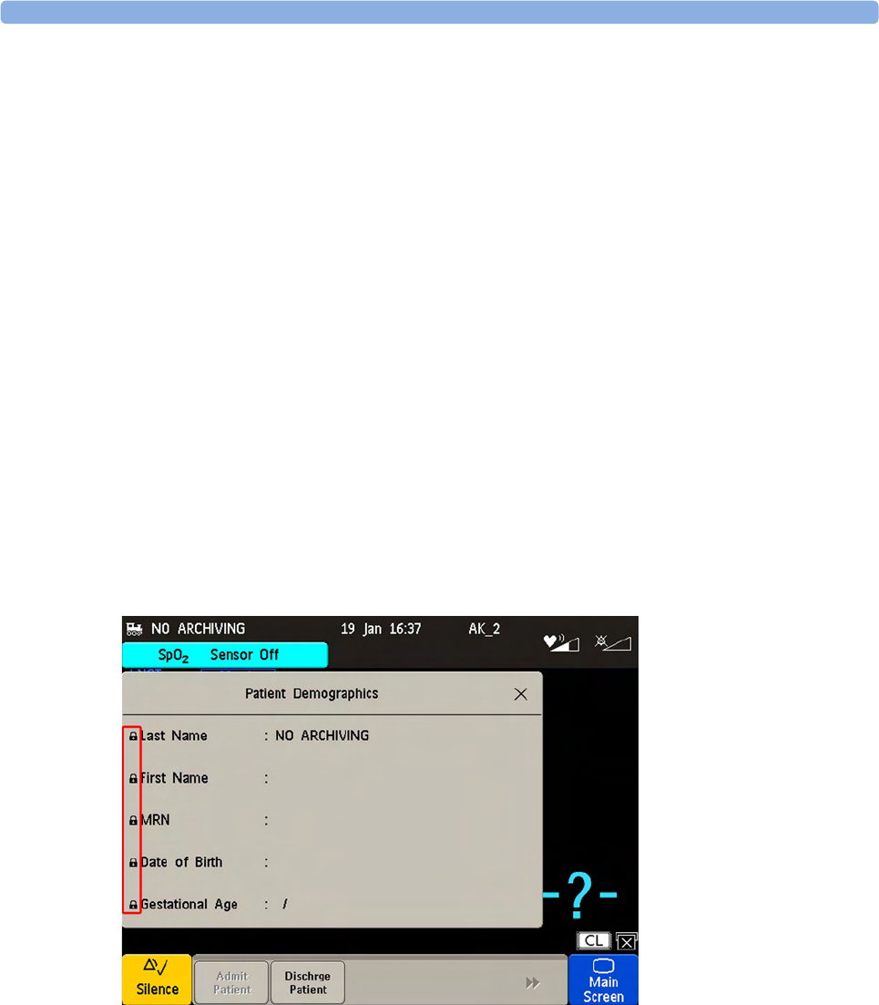
8 Admitting and Discharging
149
New Patient Check
The fetal monitor can be configured to ask you in certain situations:
• after a specified power-off period
• after a specified standby period
whether a new patient is now being monitored. The pop-up window is entitled Is this a New Patient?.
The monitor offers a Yes key, to discharge the previous patient and begin monitoring a new patient,
and a No key, to continue monitoring with the current patient data and settings.
The time periods for the two conditions can be configured independently.
OB TraceVue/IntelliSpace Perinatal
When the monitor is connected to an OB TraceVue/IntelliSpace Perinatal system over a LAN
connection, it has the control over patient demographic data. All patient and location-related data
visible on the monitor is set, overwritten, or updated by the OB TraceVue/IntelliSpace Perinatal
system. In the Patient Demographics window, a padlock symbol before the patient identification fields
indicates the locked state. The locked state prevents the reuse of the monitor for another patient, until
the current patient is discharged, and the monitor is freed through the OB TraceVue/IntelliSpace
Perinatal system. Locked fields remain locked when system connectivity is lost, until the monitor is
freed by discharging the patient. See the OB TraceVue/IntelliSpace Perinatal Instructions for Use for
details.
Transferring a Patient
When you are transferring a patient from one bed to another, both the monitor from which you are
transferring her and the monitor to which you are transferring her must be switched on and connected
to the OB TraceVue/IntelliSpace Perinatal network during the patient transfer.

8 Admitting and Discharging
150
OB TraceVue/IntelliSpace Perinatal via RS232
In contrast to a LAN connection, when the monitor is connected to an OB TraceVue/IntelliSpace
Perinatal system over an RS232 connection, the OB TraceVue/IntelliSpace Perinatal system does not
have full control over the monitor's patient admission and discharge functions.
Depending on how OB TraceVue/IntelliSpace Perinatal is configured, either the Last Name, First Name,
and the bed label, or just the bed label alone, are taken from the OB TraceVue/IntelliSpace Perinatal
system. See the OB TraceVue/IntelliSpace Perinatal Instructions for Use for details.