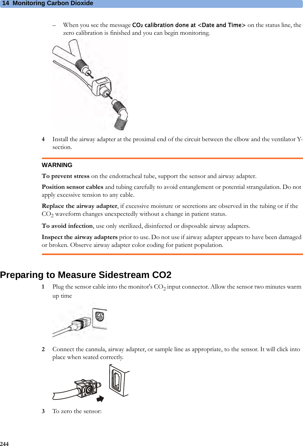
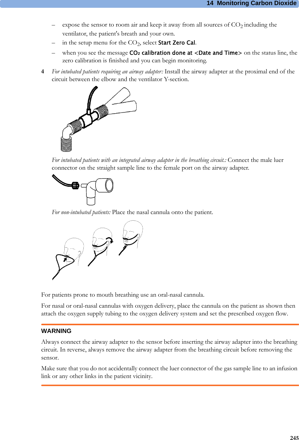
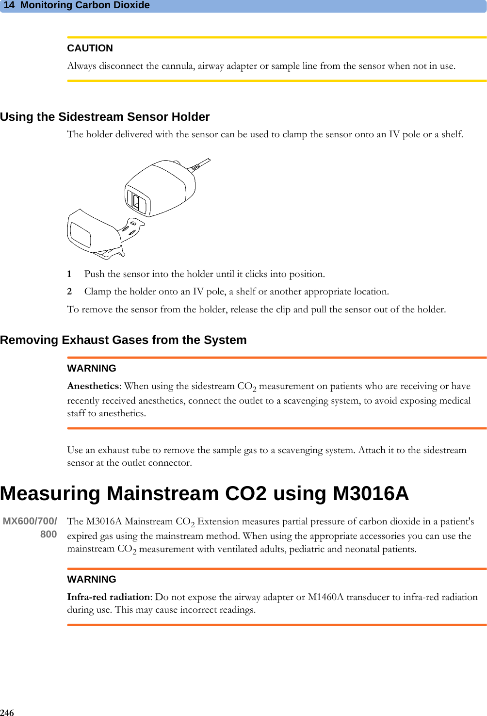
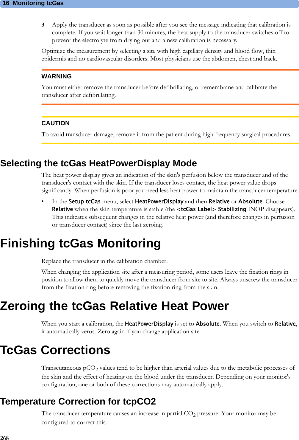
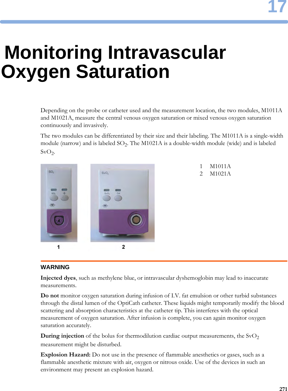
Philips Medical Systems North America SRRBV3 SRR Module User Manual ait fm manual
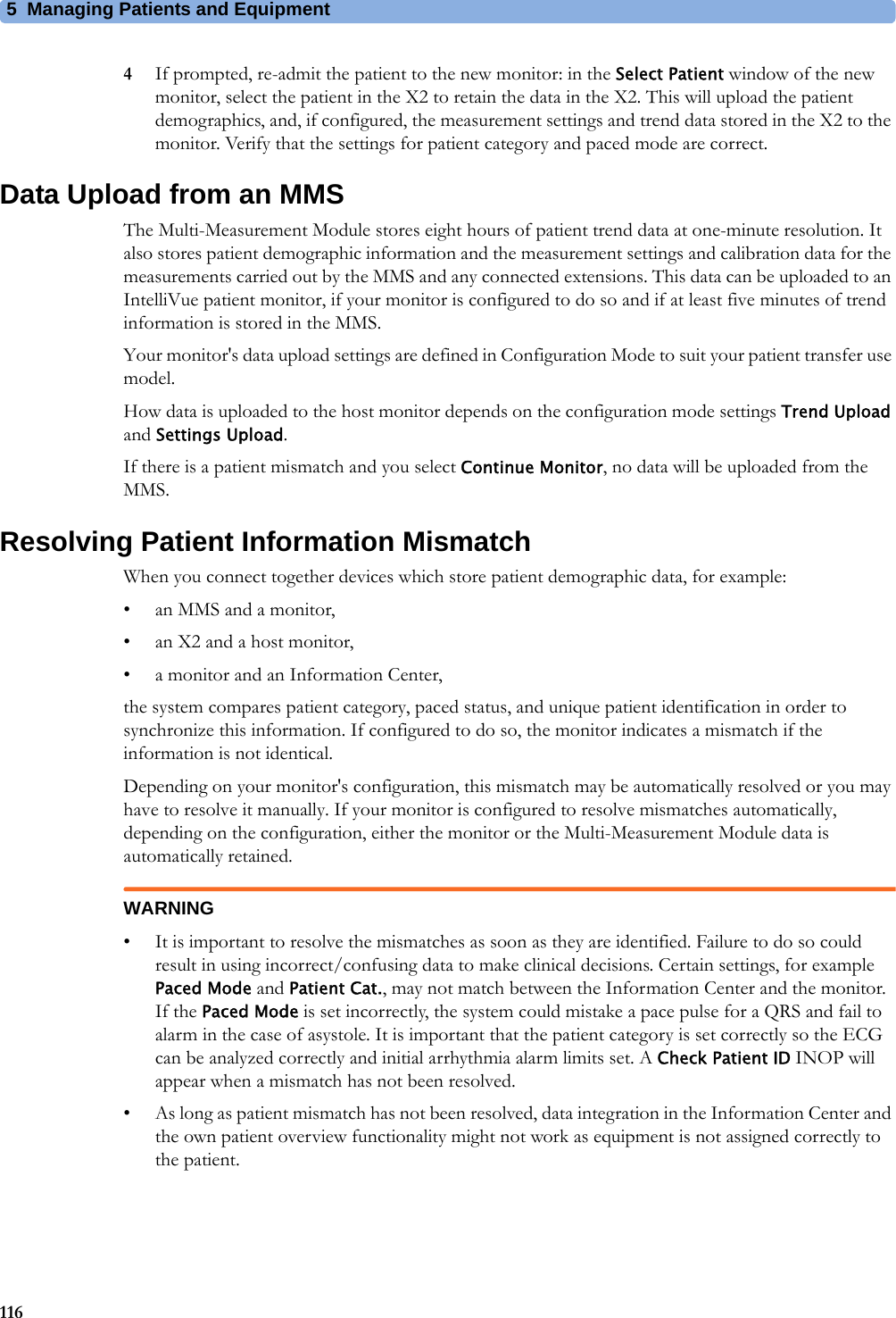
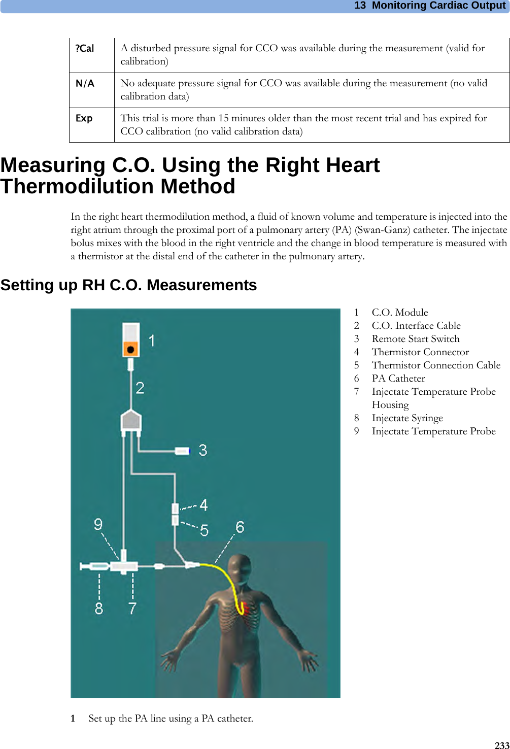
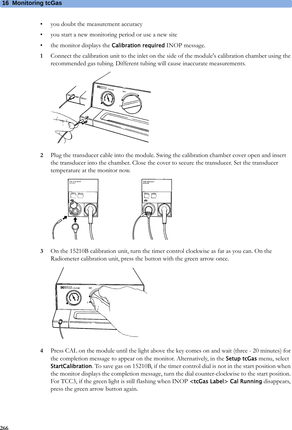
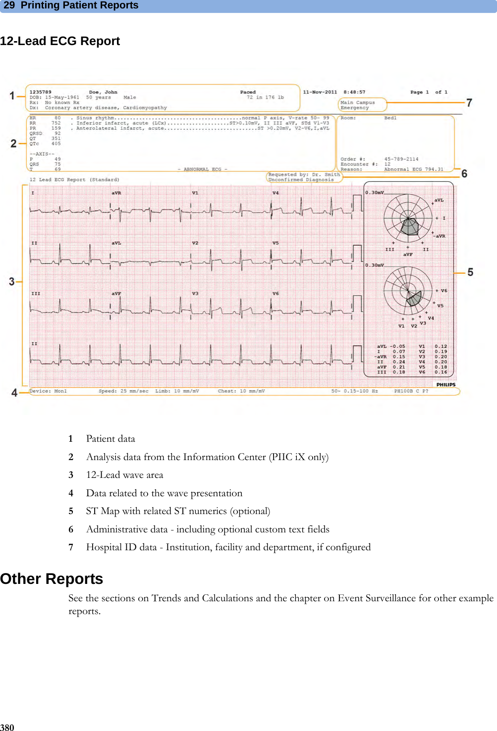
Philips Medical Systems North America Co. SRR Module ait fm manual
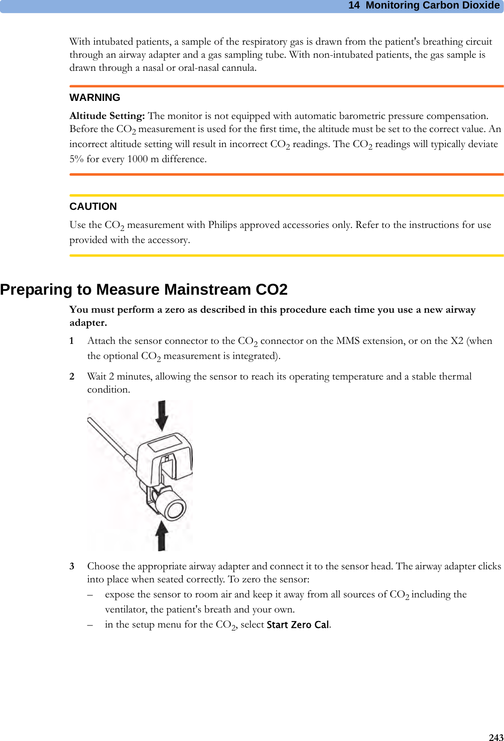
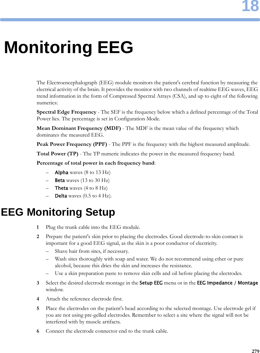
UserManual.wiki
>
Philips Medical Systems North America
>
SRRBV3 User Manual
IfU example english
Navigation menu
Upload a User Manual
Namespaces
Wiki Guide
HTML
PDF
Info
Views
User Manual
Discussion / Help
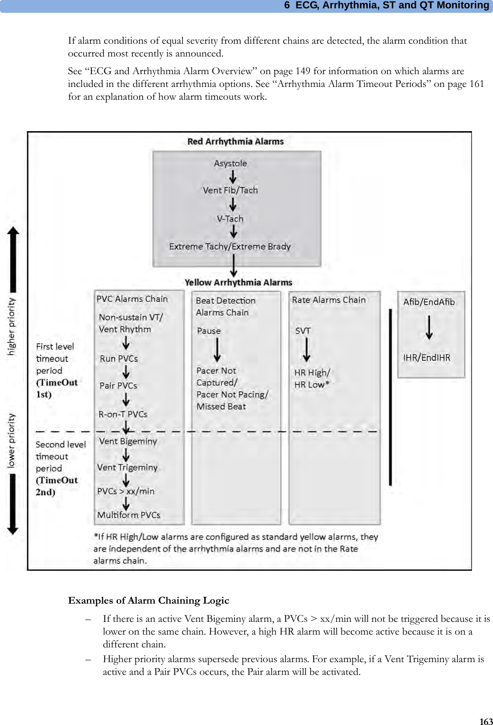
Navigation
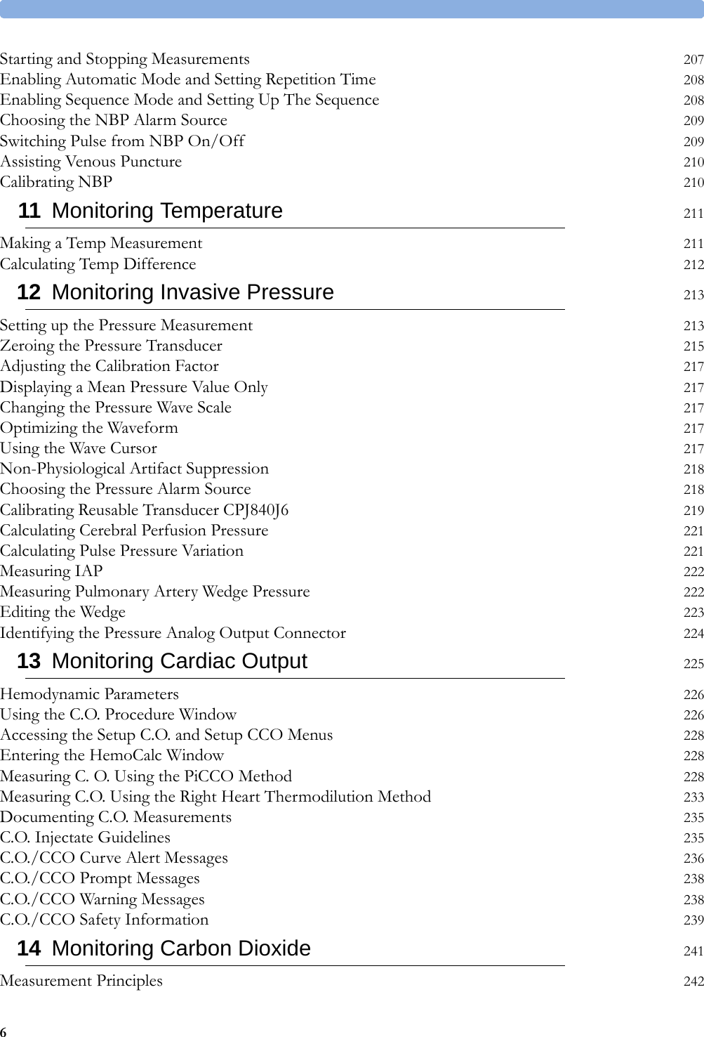


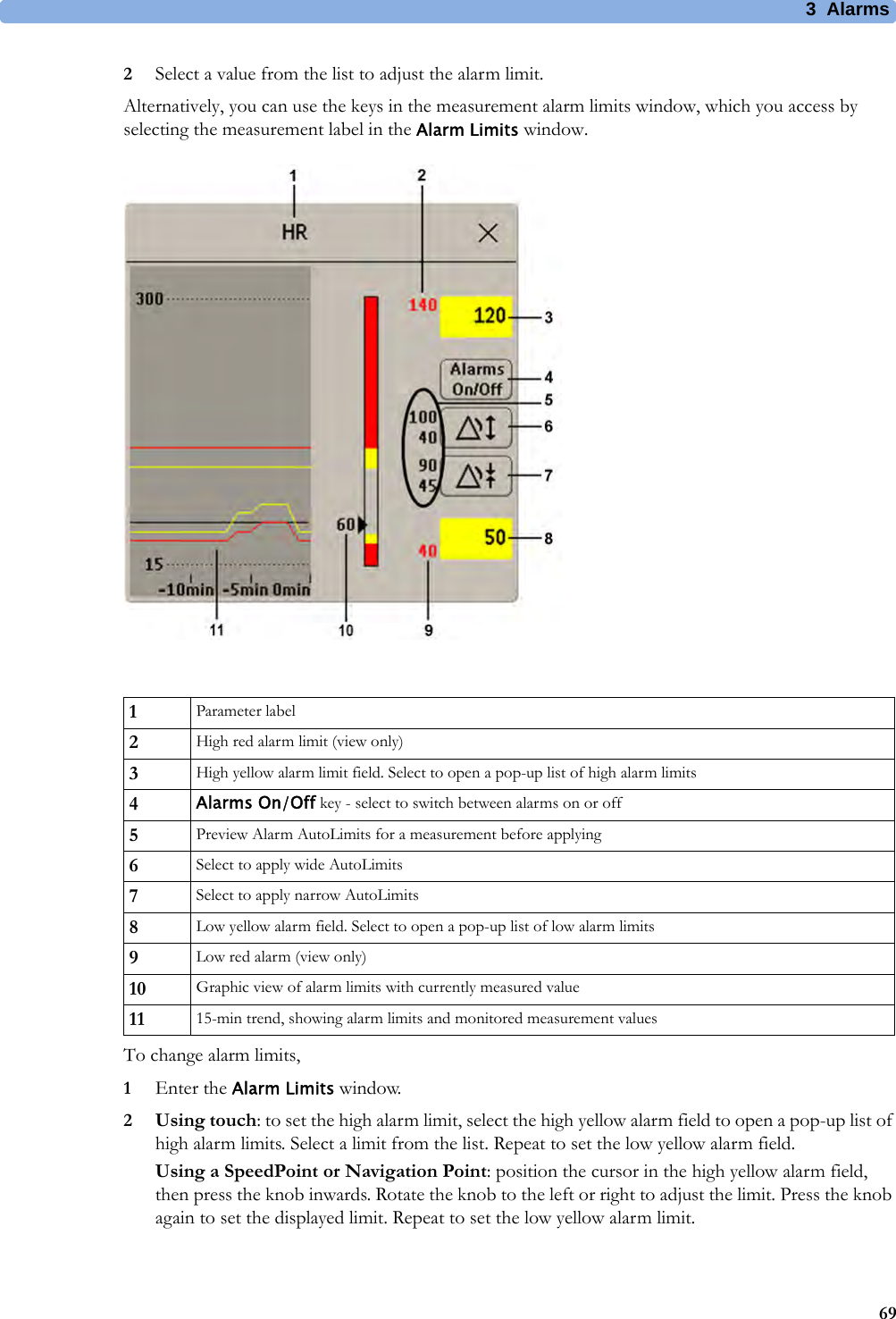
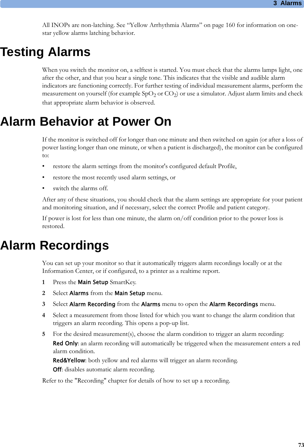

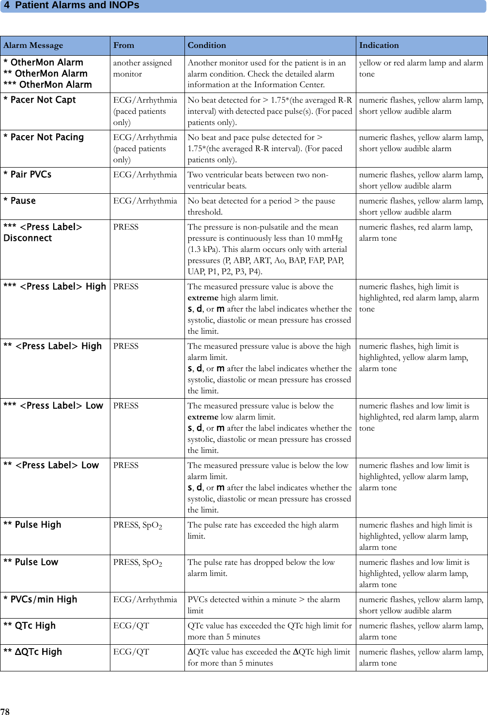
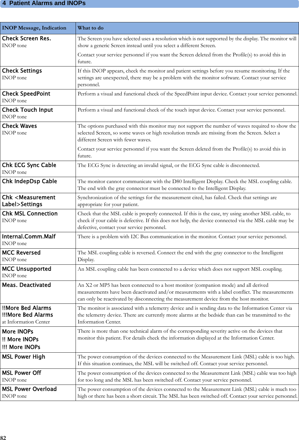
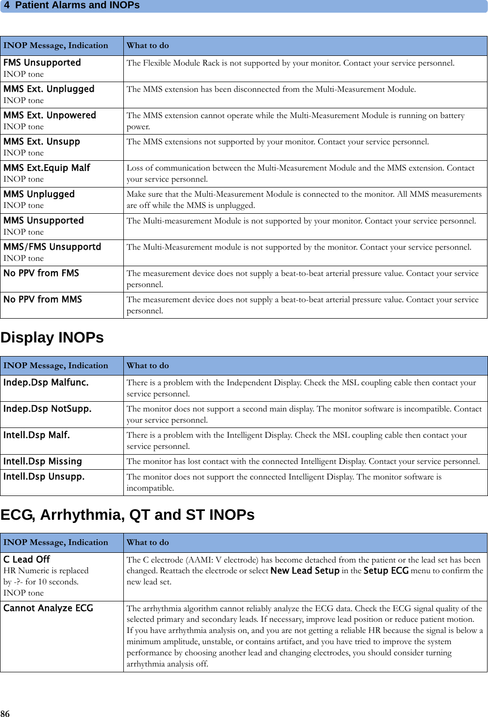
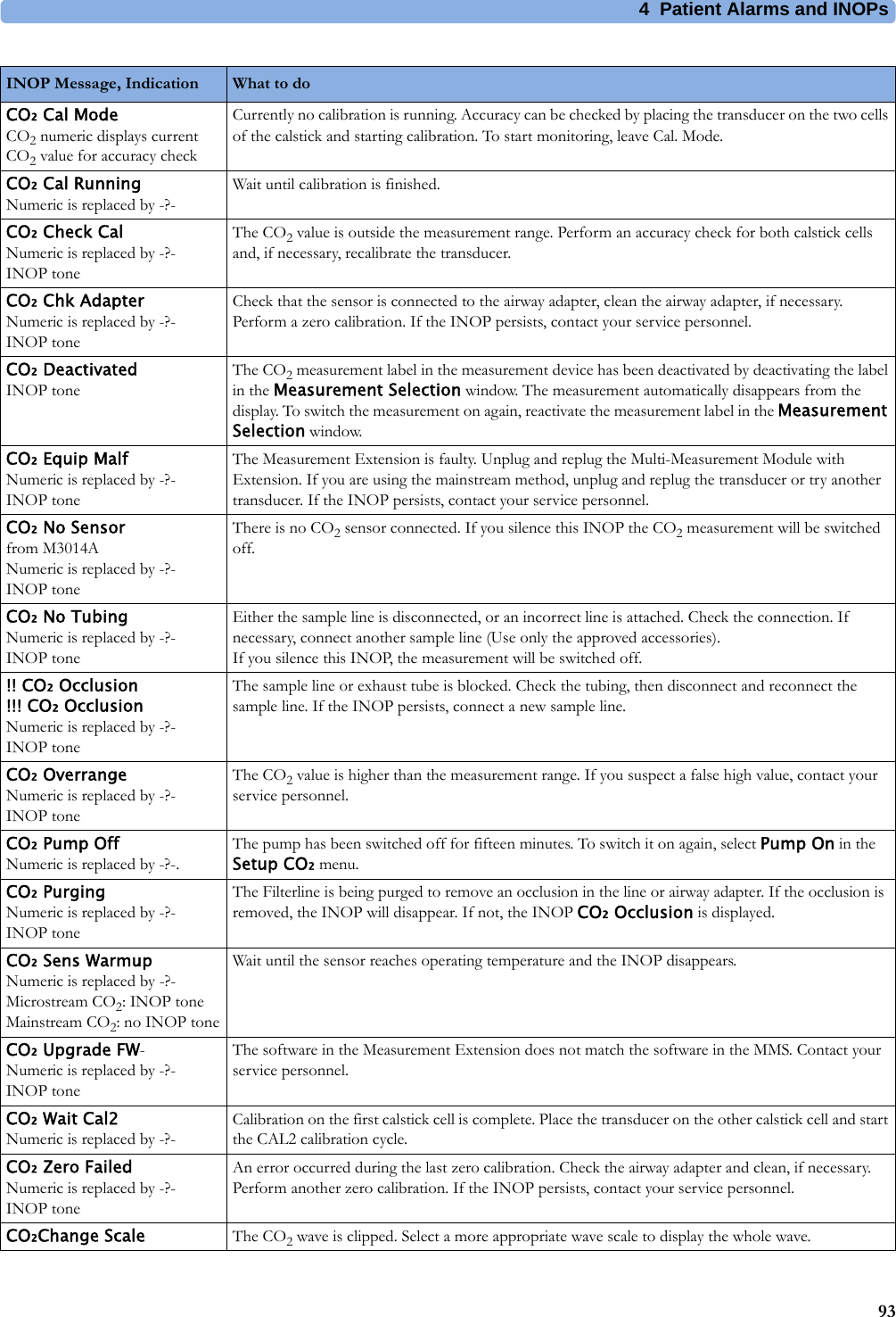
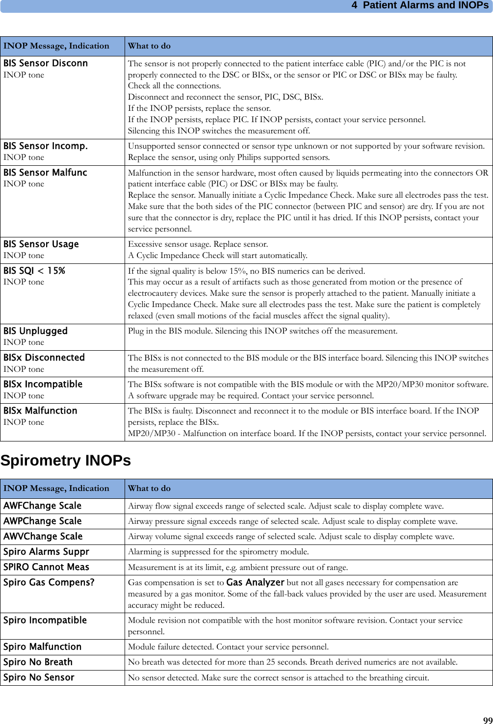
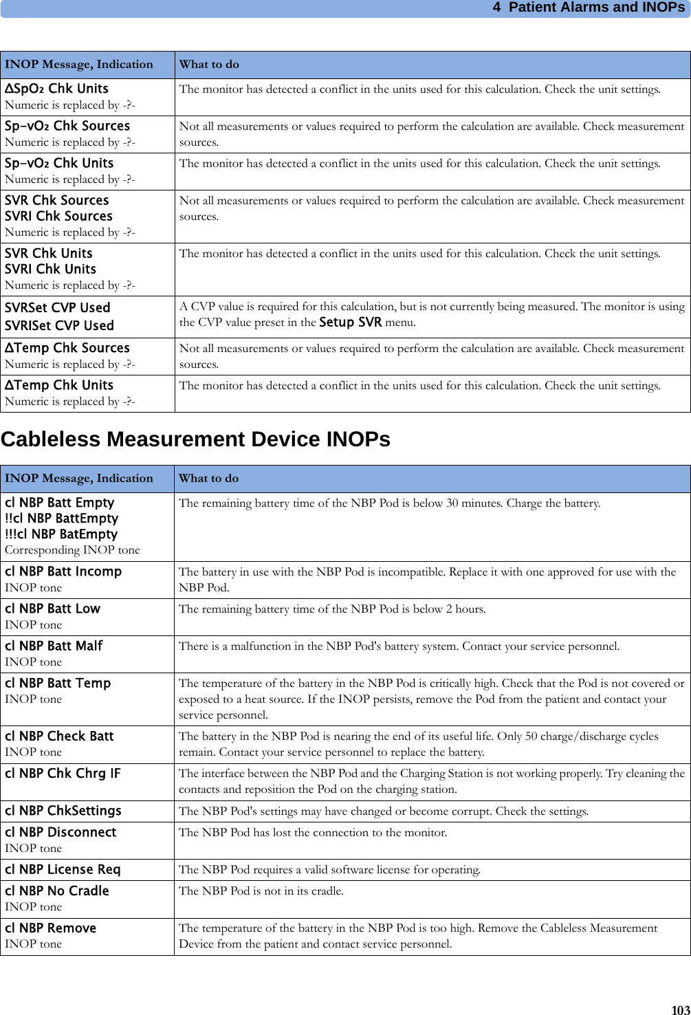
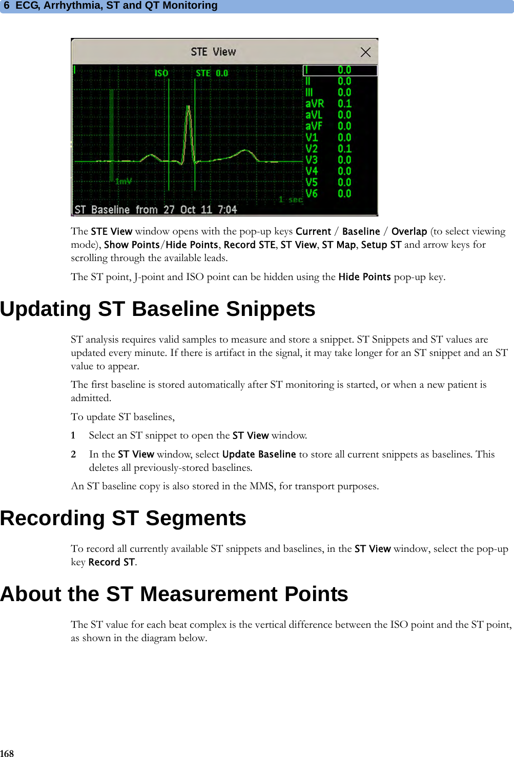
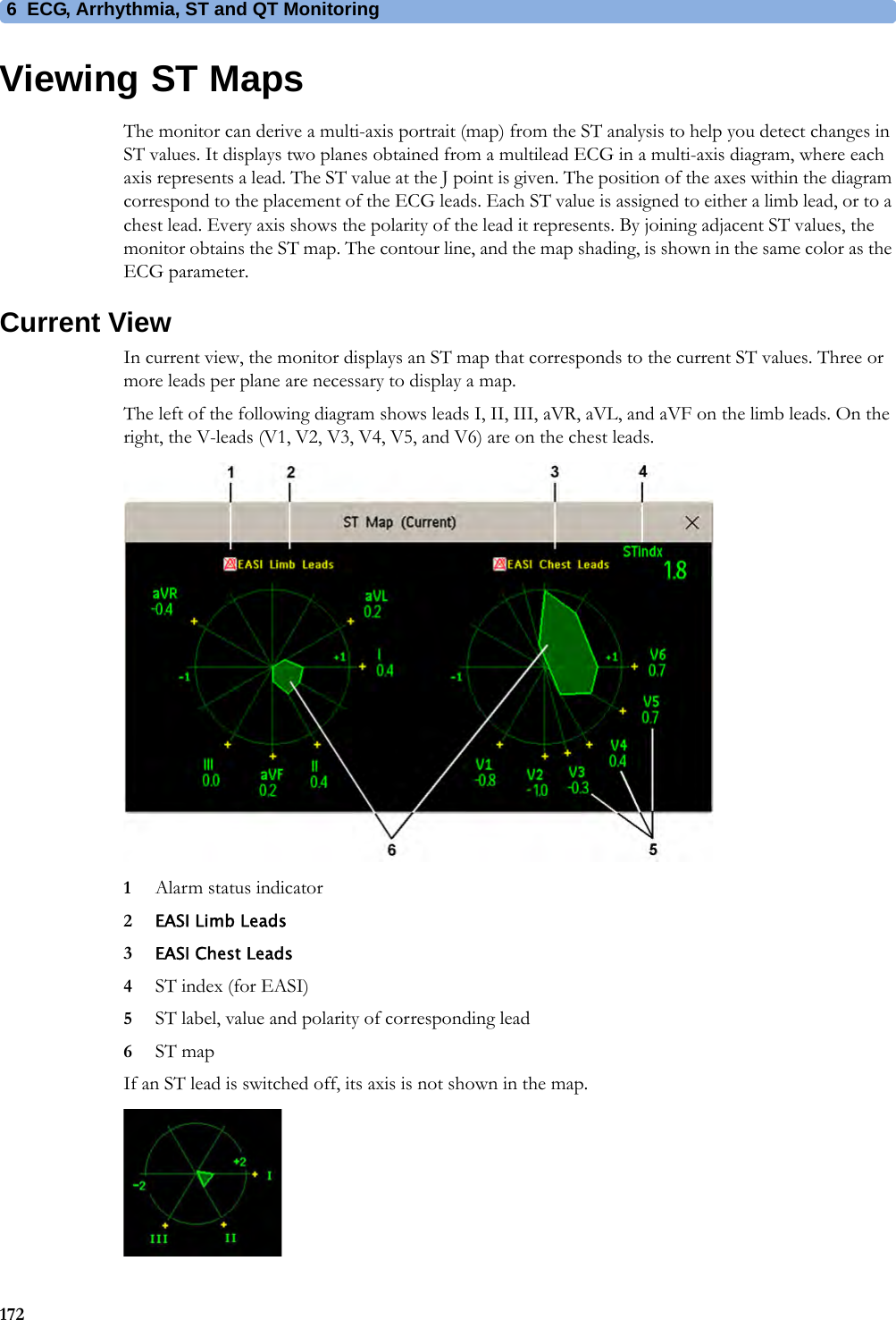
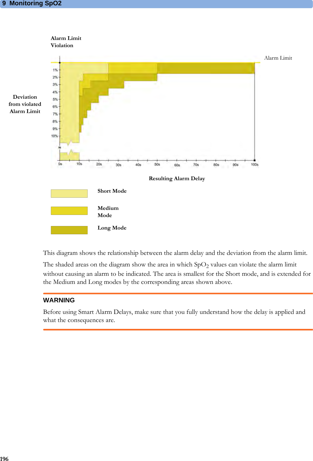
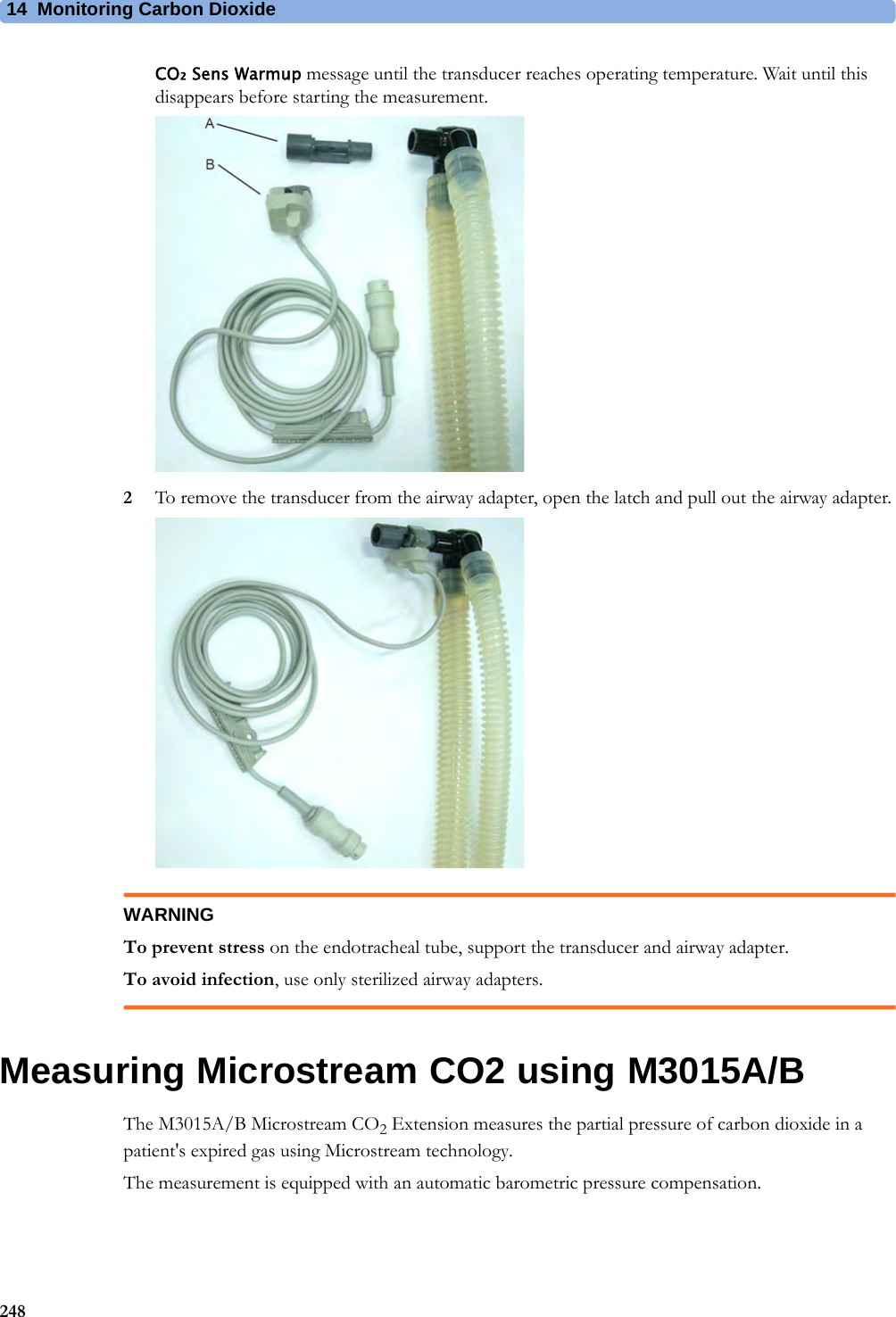
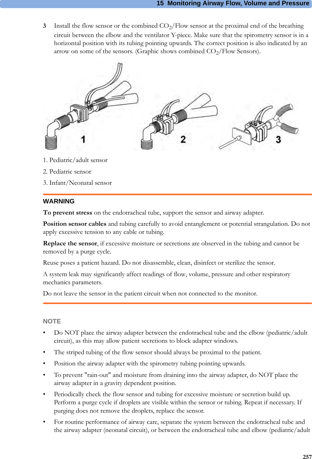
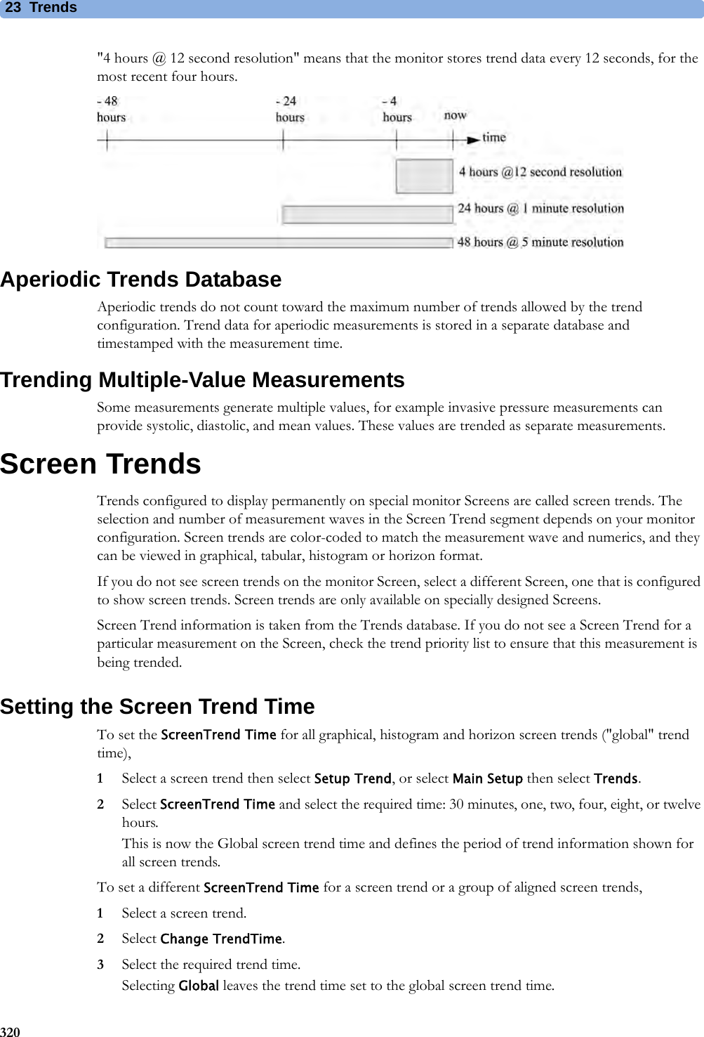
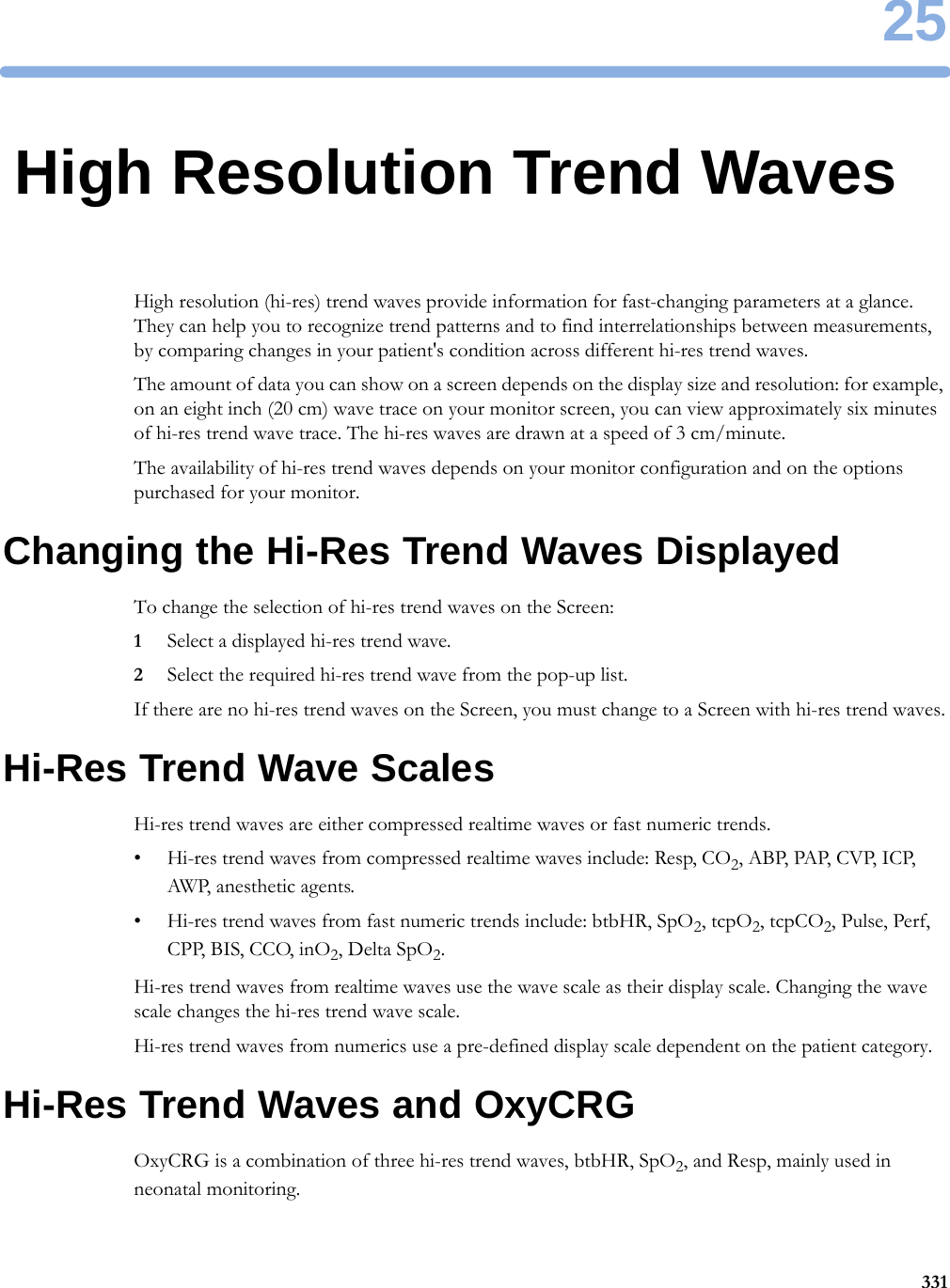
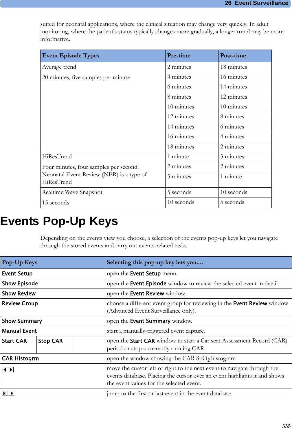
![4 Patient Alarms and INOPs87Cannot Analyze QT The QT algorithm cannot generate a valid QT value for more than 10 minutes, or 1 minute in the initial phase.Cannot Analyze ST The ST algorithm cannot generate a valid ST value. Possible causes are large variations in the measured ST values for consecutive beats, or ventricular paced beats. Review the ECG signal quality and the ST measurement points. If the patient has a ventricular pacemaker, ST analysis is not possible.Cannot Analyze STE The STE algorithm cannot generate valid ST elevation values. Possible causes are large variations in the measured ST values for consecutive beats, or ventricular paced beats. Review the ECG signal quality and the ST measurement points.ECG Equip MalfNumeric is replaced by -?-INOP toneContact your service personnel.The ECG hardware is faulty.<ECG Lead> Lead Off!! <ECG Lead> Lead Off!!! <ECG Lead> Lead OffNumeric is replaced by -?-INOP toneNot all the required leads for ECG monitoring are connected. Check the ECG connections and make sure that the electrode indicated by <ECG lead> [RA, LA, LL, RL, V or C] electrodes is attached. In EASI mode, all 5 electrodes must be connected.ECG Leads Off!! ECG Leads Off!!!ECG Leads OffNumeric is replaced by -?-INOP toneCheck that all of the required ECG leads are attached, and that none of the electrodes have been displaced. The INOP may also be caused by a saturated or overloaded ECG amplifier.ECG Noisy Elec <ECG Lead>The ECG signal from the named ECG electrodes [RA, LA, LL, RL, V (or C)] is noisy. Check the ECG connections and make sure that the electrode indicated is attached.ECG Noisy SignalINOP toneThe ECG signal is too noisy. Check that the electrodes are properly placed and have not dried out. Remove any possible sources of signal noise (such as power cords) from the area around the cable and the patient.The ECG signal may be saturated or overloaded.ECG Out Equip MalfINOP toneThere is a problem with the device connected to the ECG Out connector. Contact your service personnel.!!ECG/Ar AlarmsOff All ECG alarms have been switched off, or the HR alarm source is not ECG. To resume ECG alarm generation, switch ECG alarms on or select ECG as the alarm source.ECG/Arrh AlarmsOff!!ECG/Ar AlarmsOffAll ECG alarms have been switched off, or the HR alarm source is not ECG. To resume ECG alarm generation, switch ECG alarms on or select ECG as the alarm source.LA Lead OffNumeric is replaced by -?- for 10 seconds.INOP toneThe LA electrode has become detached from the patient or the lead set has been changed. Reattach the electrode or select New Lead Setup in the Setup ECG menu to confirm the new lead set.LL Lead OffNumeric is replaced by -?- for 10 seconds.INOP toneThe LL electrode has become detached from the patient or the lead set has been changed. Reattach the electrode or select New Lead Setup in the Setup ECG menu to confirm the new lead set.RA Lead OffNumeric is replaced by -?-INOP toneThe RA electrode has become detached from the patient or the lead set has been changed. Reattach the electrode or select New Lead Setup in the Setup ECG menu to confirm the new lead set.RL Lead OffNumeric is replaced by -?- for 10 seconds.INOP toneThe RL electrode has become detached from the patient or the lead set has been changed. Reattach the electrode or select New Lead Setup in the Setup ECG menu to confirm the new lead set.Some ECG AlarmsOff This message appears (if configured to do so) when the on/off settings of the yellow arrhythmia alarms differ from the current Profile.INOP Message, Indication What to do](https://usermanual.wiki/Philips-Medical-Systems-North-America/SRRBV3/User-Guide-2121007-Page-87.png)
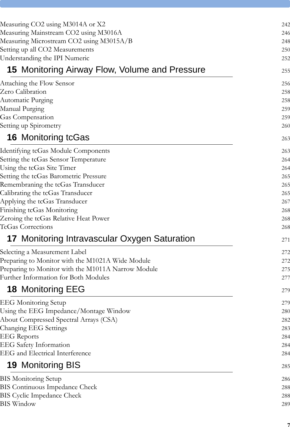
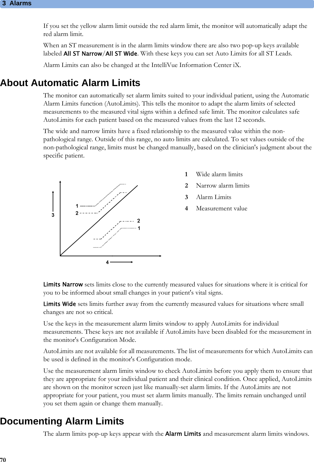
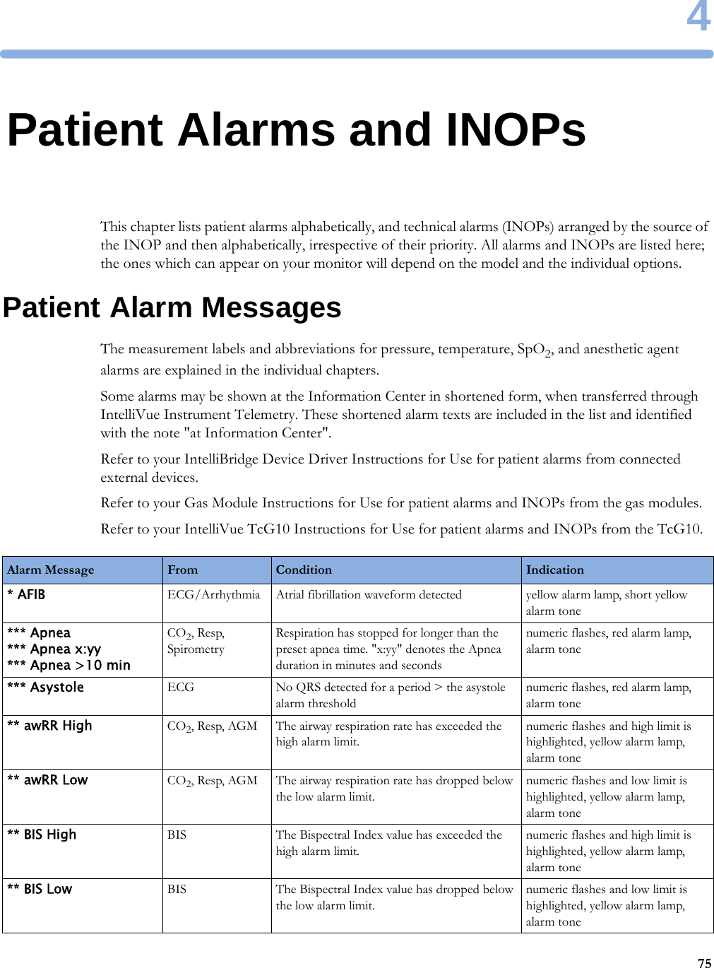
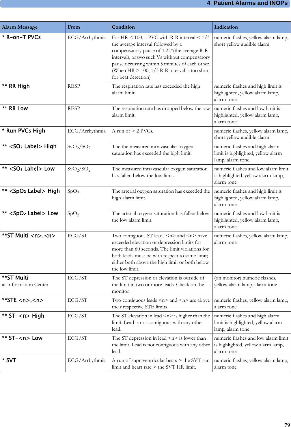
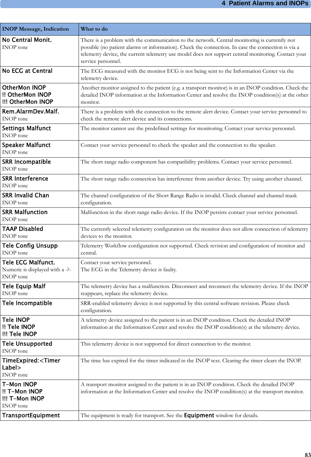
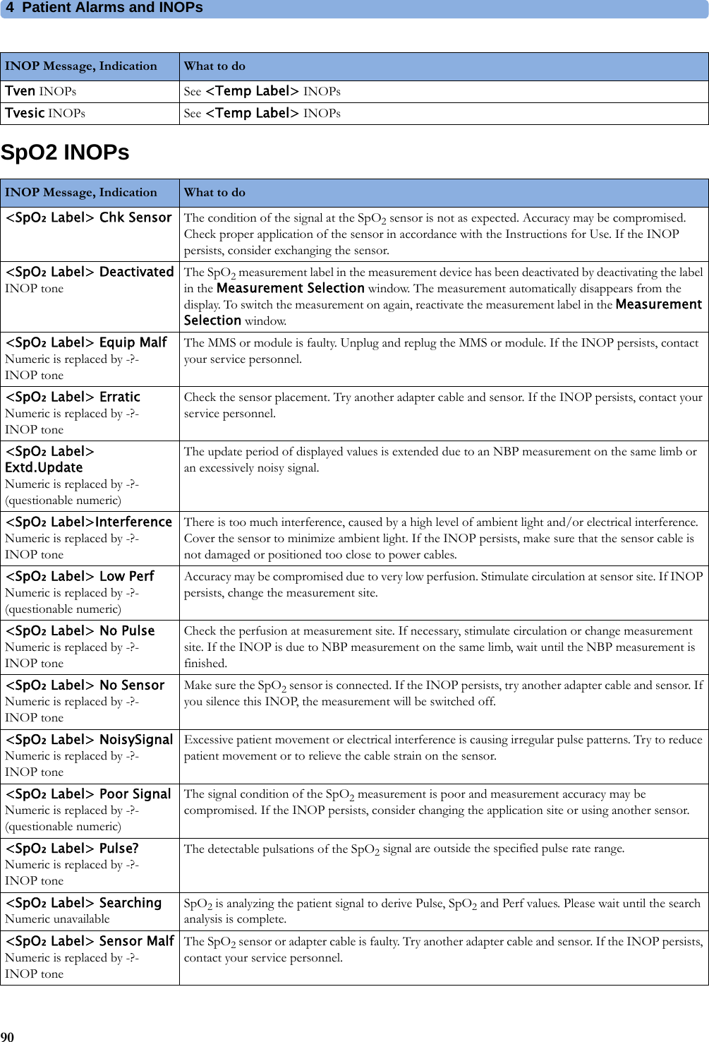
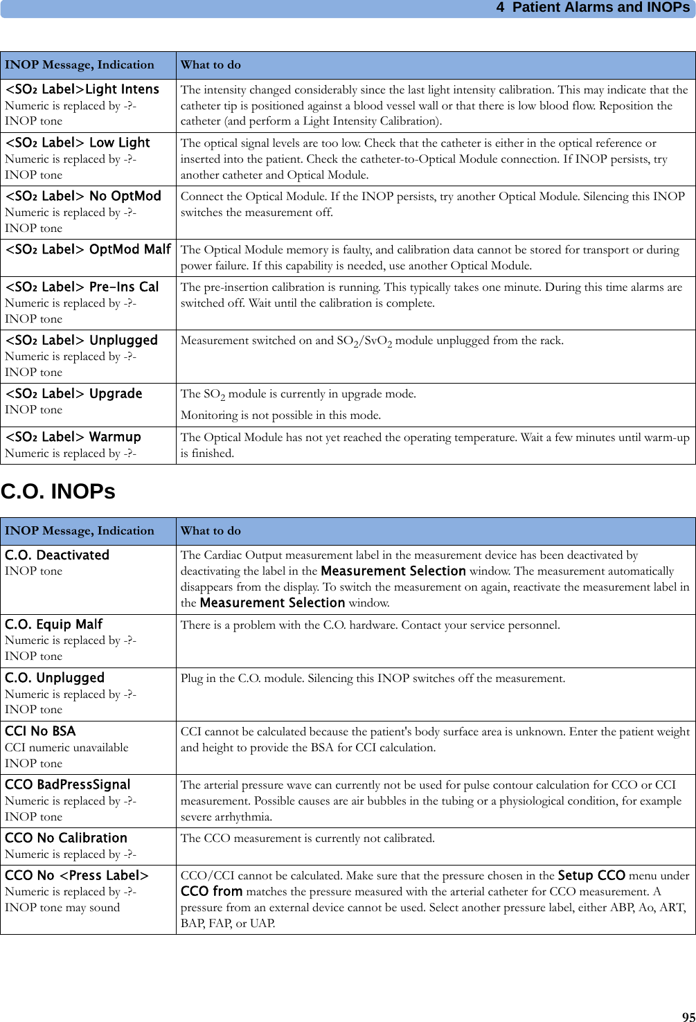
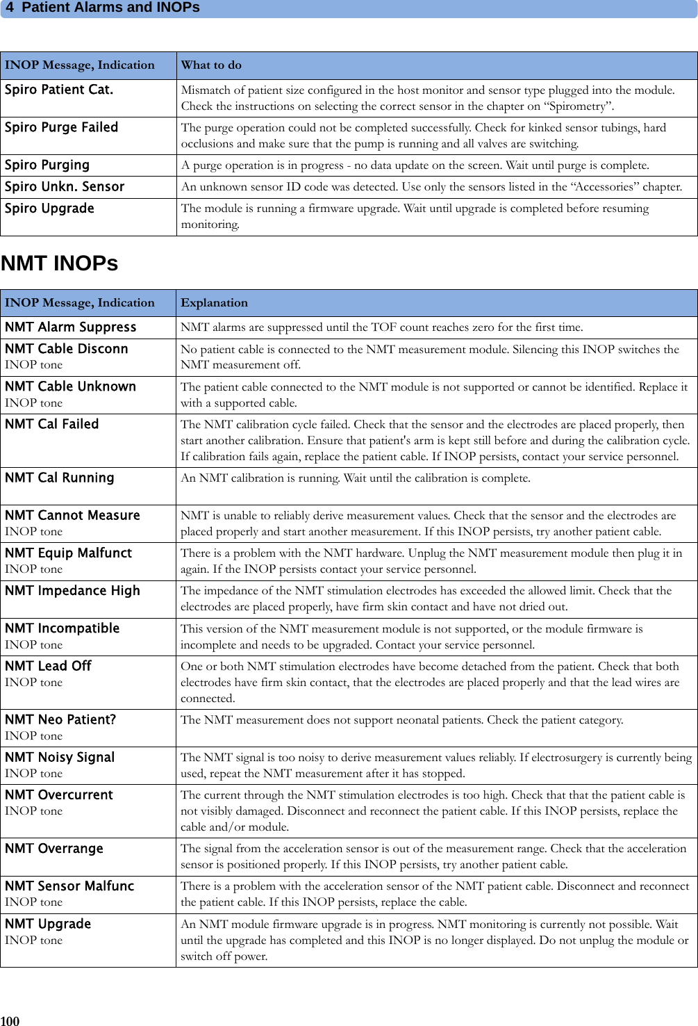
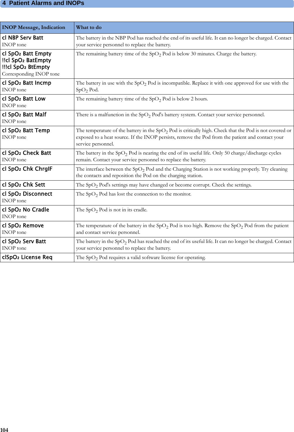
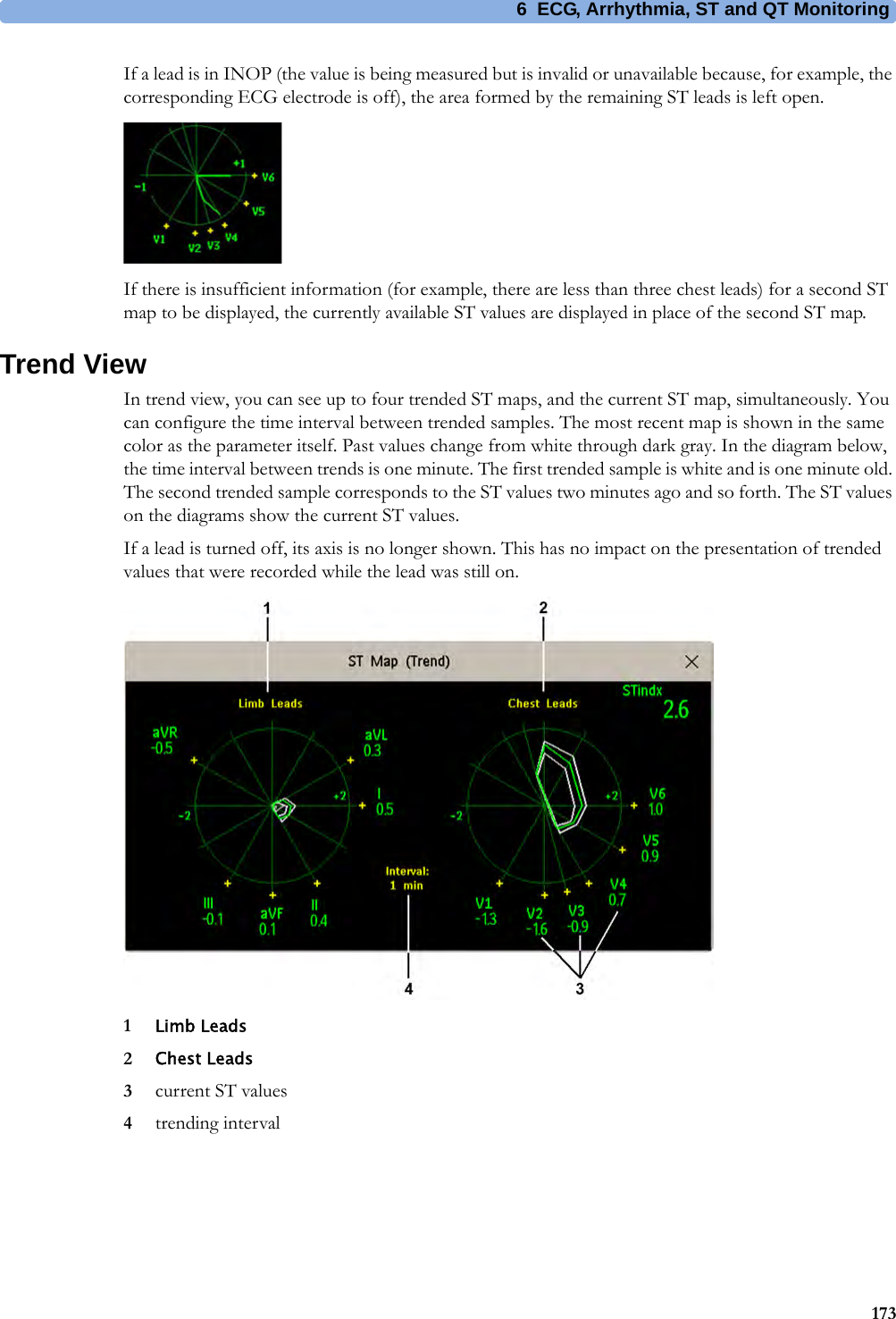
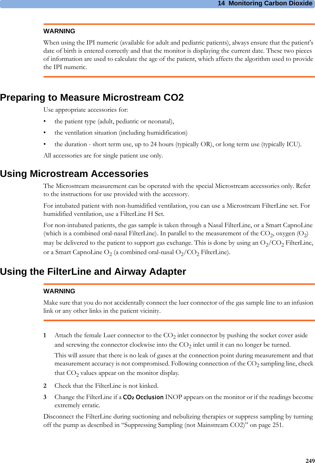
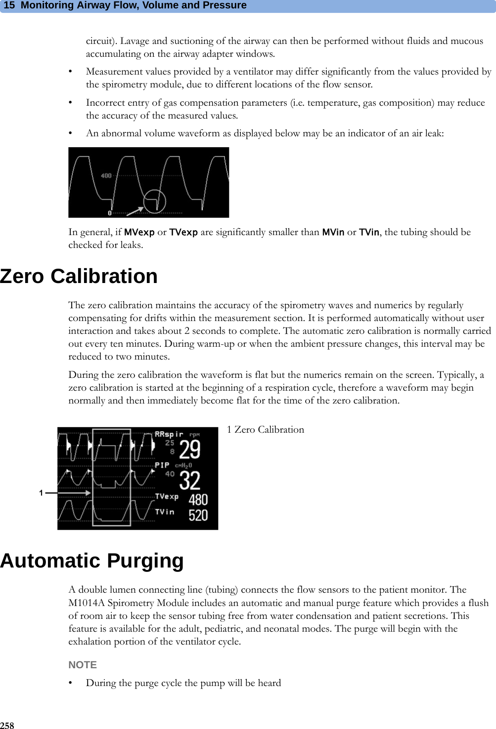
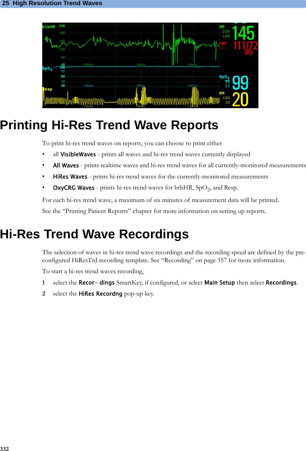
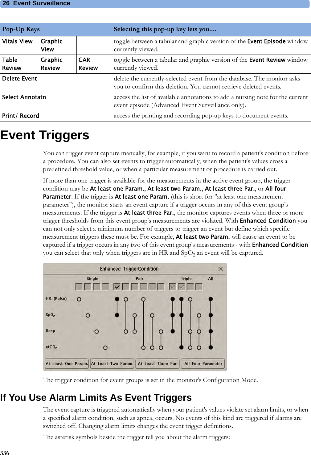
![4 Patient Alarms and INOPs88Pulse INOPsResp INOPsNBP INOPsV Lead OffNumeric is replaced by -?- for 10 seconds.INOP toneThe V electrode (IEC: C electrode) has become detached from the patient or the lead set has been changed. Reattach the electrode or select New Lead Setup in the Setup ECG menu to confirm the new lead set.INOP Message, Indication What to do INOP Message, Indication What to do Pulse Not AlarmingNumeric is replaced by -?-INOP tonePulse has no alarming because the system pulse is measured by an external device. Select another pulse source to enable pulse alarming.INOP Message, Indication What to do Resp Equip MalfNumeric is replaced by -?-INOP toneContact your service personnel. The RESP hardware is faulty.Resp ErraticNumeric is replaced by -?-The monitor has detected too many artifacts in the measured Resp signal. Check that the RA and LL electrodes are correctly attached and have not dried out.Resp Leads OffNumeric is replaced by -?-INOP toneNot all the required leads for Resp monitoring are attached. Make sure that the RA and LL leads are attached.INOP Message, Indication What to do !! Cuff Not Deflat!!!Cuff Not DeflatNumeric is displayed with a -?-Severe yellow/red INOP toneDuring this INOP, alarms cannot be paused or switched off.Remove the cuff from the patient. Make sure that the tubing is not kinked or twisted and that the correct patient category is selected. Try repeating the measurement. You can silence the INOP, but the INOP message remains visible until the next NBP measurement is started or the Stop All SmartKey is selected.[Adult or pediatric patients: The NBP cuff pressure has exceeded 15 mmHg (2 kPa) for more than 3minutes. Neonatal patients: The NBP cuff pressure has exceeded 5 mmHg (0.7 kPa) for more than 90 seconds.]!! Cuff Overpress!!!Cuff OverpressNumeric displayed with a -?-Severe yellow/red INOP toneDuring this INOP, alarms cannot be paused or switched off.The NBP cuff pressure exceeds the overpressure safety limits. Remove the cuff from the patient. Make sure that the tubing is not kinked or twisted and that the correct patient category is selected. Try restarting the measurement. You can silence this INOP, but the INOP message remains visible until the next measurement is started or the Stop All SmartKey is selected.NBP DeactivatedINOP toneThe NBP measurement label in the measurement device has been deactivated by deactivating the label in the Measurement Selection window. The measurement automatically disappears from the display. To switch the measurement on again, reactivate the measurement label in the Measurement Selection window.NBP Equip MalfNumeric is replaced by -?-INOP toneRemove the cuff from the patient. The NBP hardware is faulty. Contact your service personnel. You can silence this INOP, but the INOP message remains visible until the next measurement is started or the Stop All SmartKey is selected.](https://usermanual.wiki/Philips-Medical-Systems-North-America/SRRBV3/User-Guide-2121007-Page-88.png)
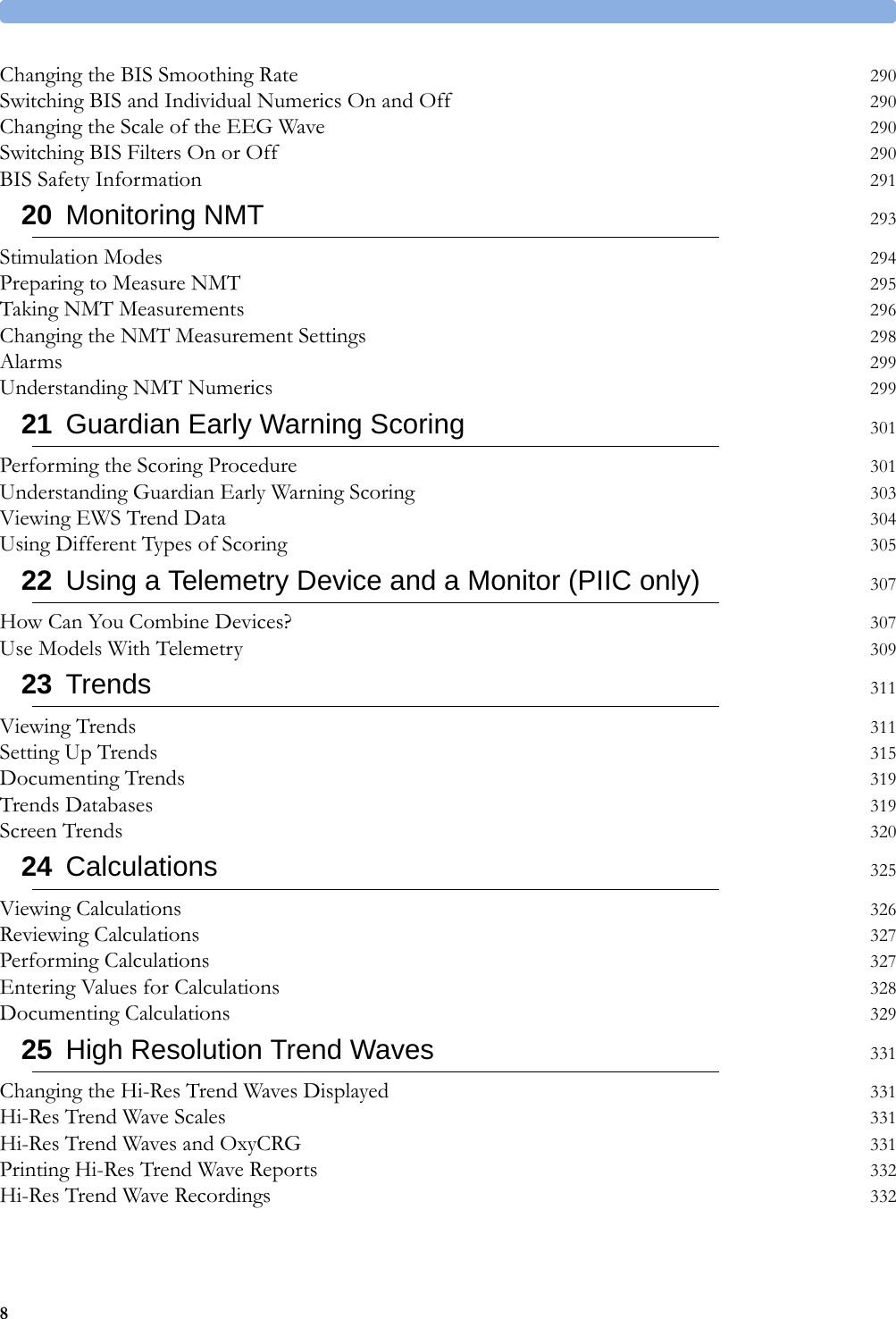
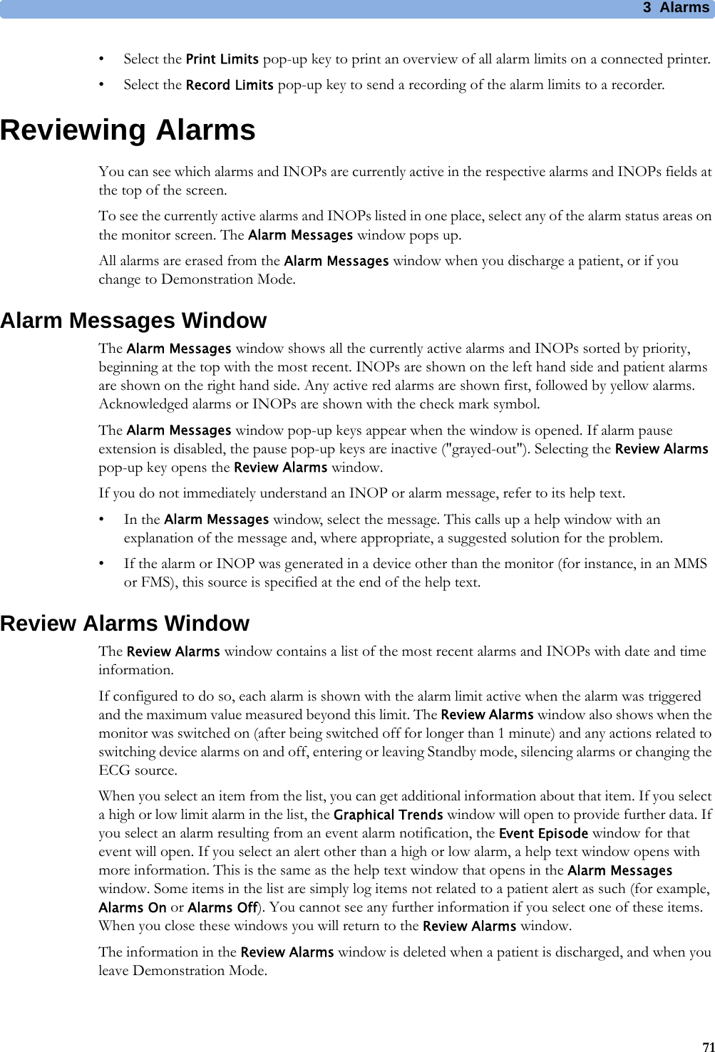
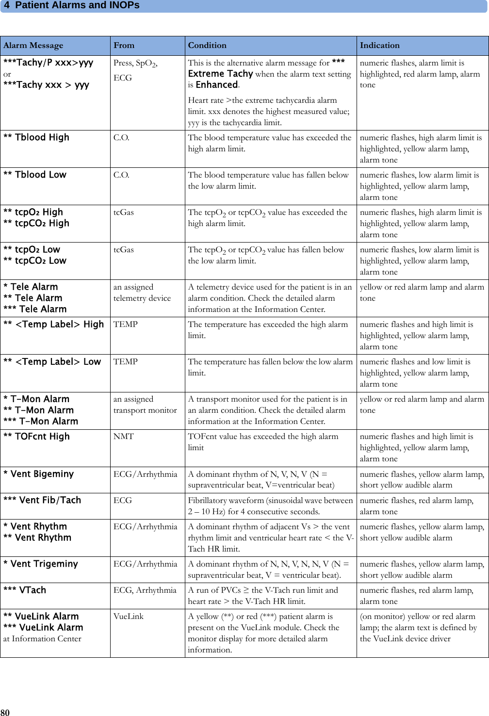
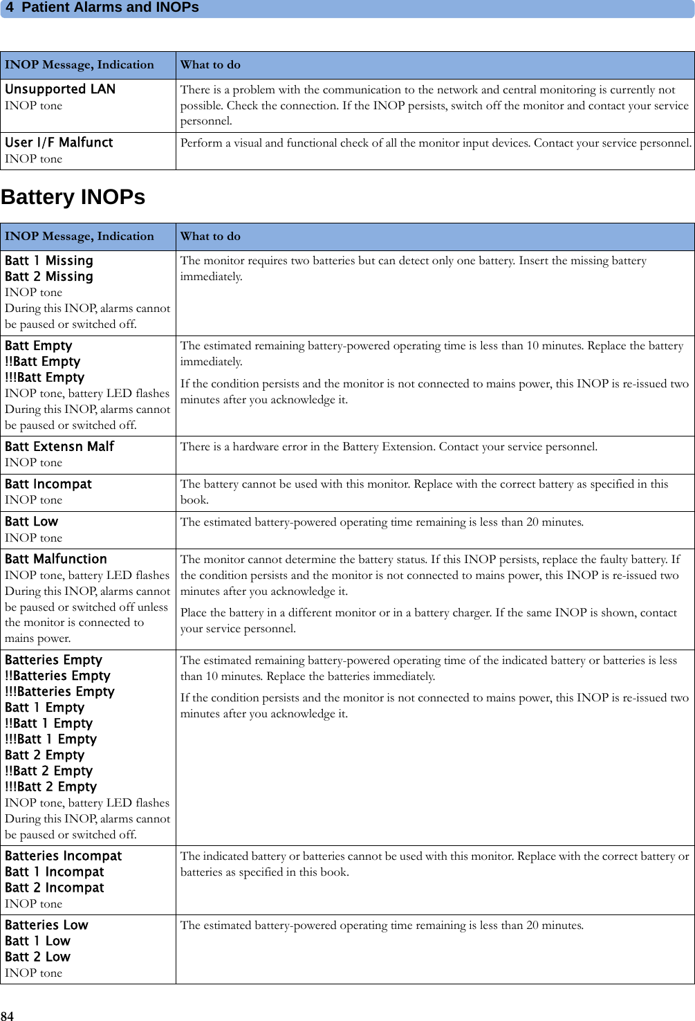
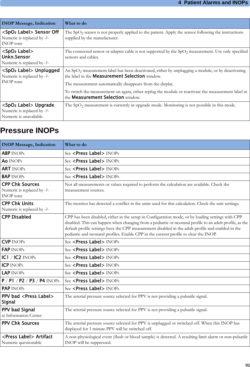
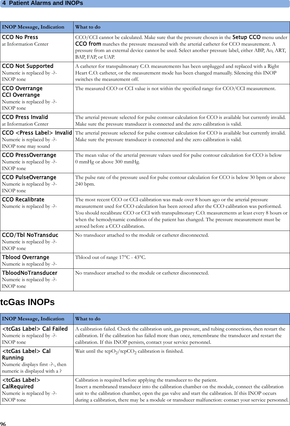
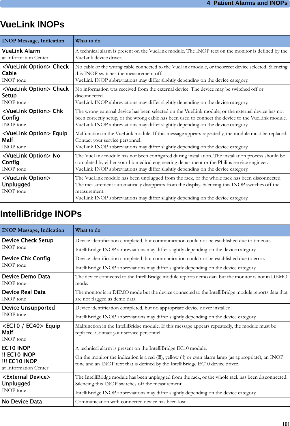
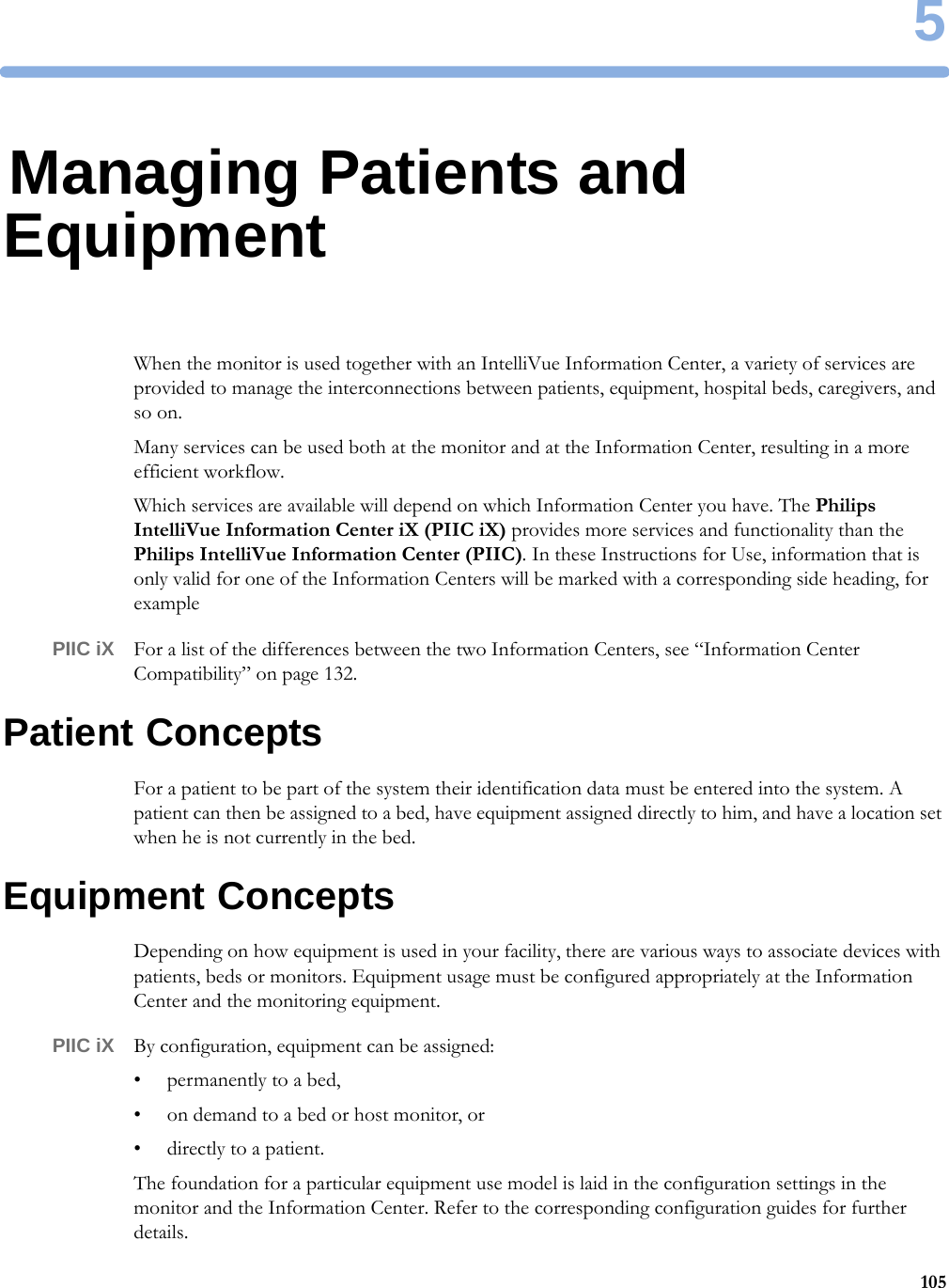
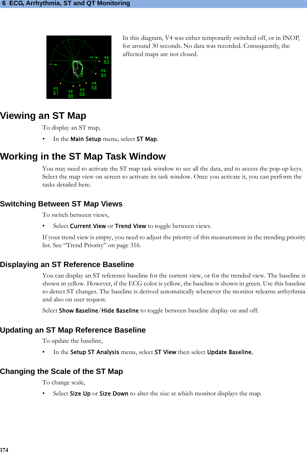
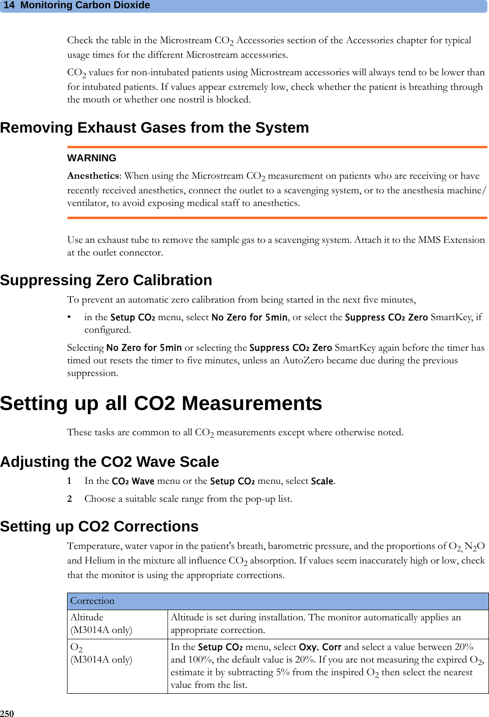
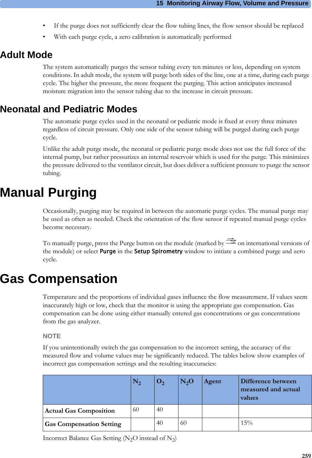
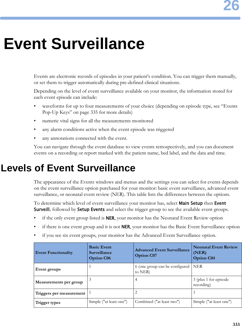
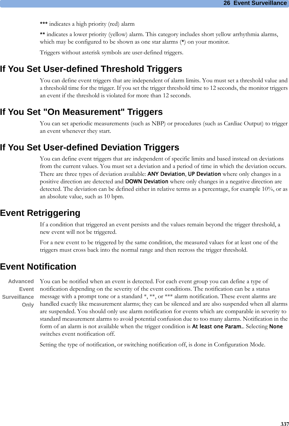
![4 Patient Alarms and INOPs89Temperature INOPsNBP InterruptedNumeric is replaced by -?-INOP toneCheck the tubing and cuff for leakages or kinks. Check that you are using the correct cuff size and placement, and that the correct patient category is selected. Try restarting the measurement. If the INOP occurs repeatedly, contact your service personnel.You can silence this INOP, but the INOP message remains visible until the next measurement is started or the Stop All SmartKey is selected.This INOP arises when the measurement needed longer than the maximum time for inflation, deflation or the total measurement.NBP Measure FailedNumeric may be displayed with a-?-INOP toneCheck that you are using the correct cuff size and placement, and that the correct patient category is selected. Try restarting the measurement.You can silence this INOP, but the INOP message remains visible until the next measurement is started or the Stop All SmartKey is selected.Check the condition and suitability of the patient for NBP monitoring. Use another cuff to continue measuring.INOP Message, Indication What to do INOP Message, Indication What to do T1, T2, T3, T4 INOPs See <Temp Label> INOPsTamb INOPs See <Temp Label> INOPsTart INOPs See <Temp Label> INOPsTcereb INOPs See <Temp Label> INOPsTcore INOPs See <Temp Label> INOPs<Temp Label> DeactivatedINOP toneA Temp measurement label in the measurement device has been deactivated, either by connecting a Pressure transducer in the shared Press/Temp socket, or by deactivating the label in the Measurement Selection window.The measurement automatically disappears from the display.To switch the measurement on again, either reconnect a Temp transducer or reactivate the measurement label in the Measurement Selection window.<Temp Label> Equip MalfNumeric is replaced by -?-INOP toneContact your service personnel.The temperature hardware is faulty.<Temp Label>NoTransducerNumeric is replaced by -?-INOP toneMake sure the TEMP probe is connected to the MMS or module.If you silence this INOP, the measurement will be switched off.<Temp Label> OverrangeNumeric is replaced by -?-INOP toneTry changing the application site of the transducer.[The temperature is less than -1°C, or greater than 45°C.]<Temp Label> UnpluggedINOP toneA Temp measurement label has been deactivated, either by unplugging a module, or by deactivating the label in the Measurement Selection window.The measurement automatically disappears from the display.To switch the measurement on again, either replug the module or reactivate the measurement label in the Measurement Selection window.Tesoph INOPs See <Temp Label> INOPsTnaso INOPs See <Temp Label> INOPsTrect INOPs See <Temp Label> INOPsTskin INOPs See <Temp Label> INOPsTtymp INOPs See <Temp Label> INOPs](https://usermanual.wiki/Philips-Medical-Systems-North-America/SRRBV3/User-Guide-2121007-Page-89.png)
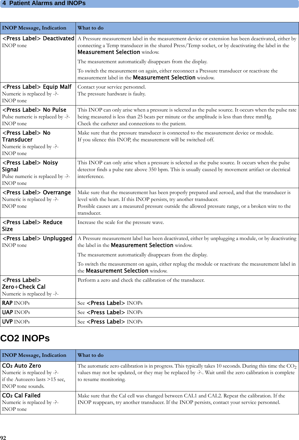

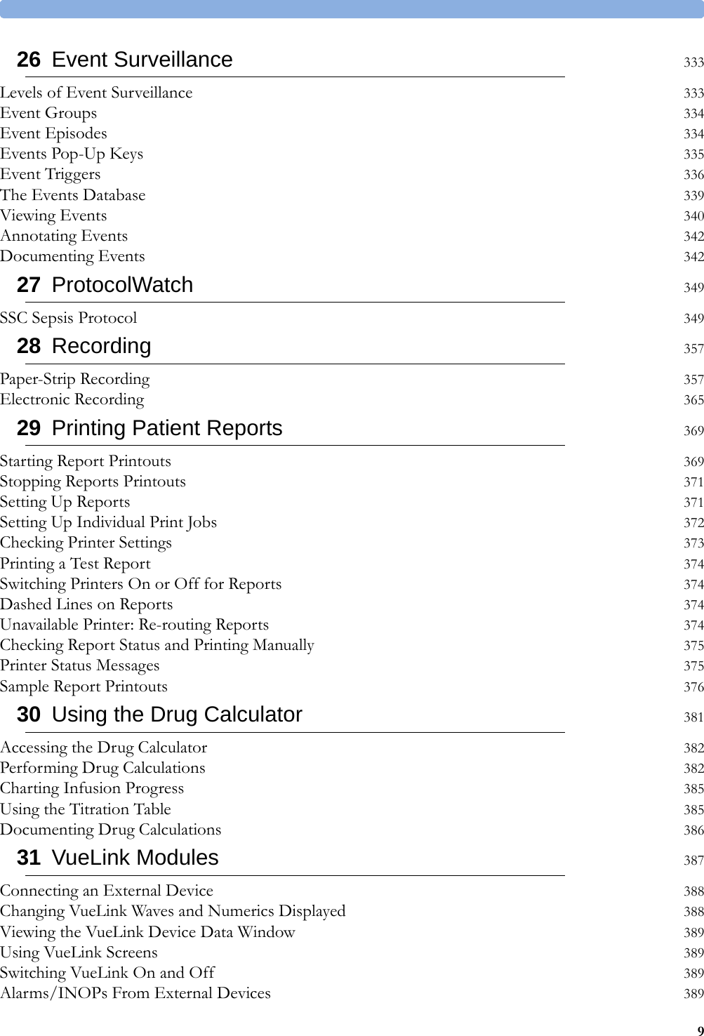
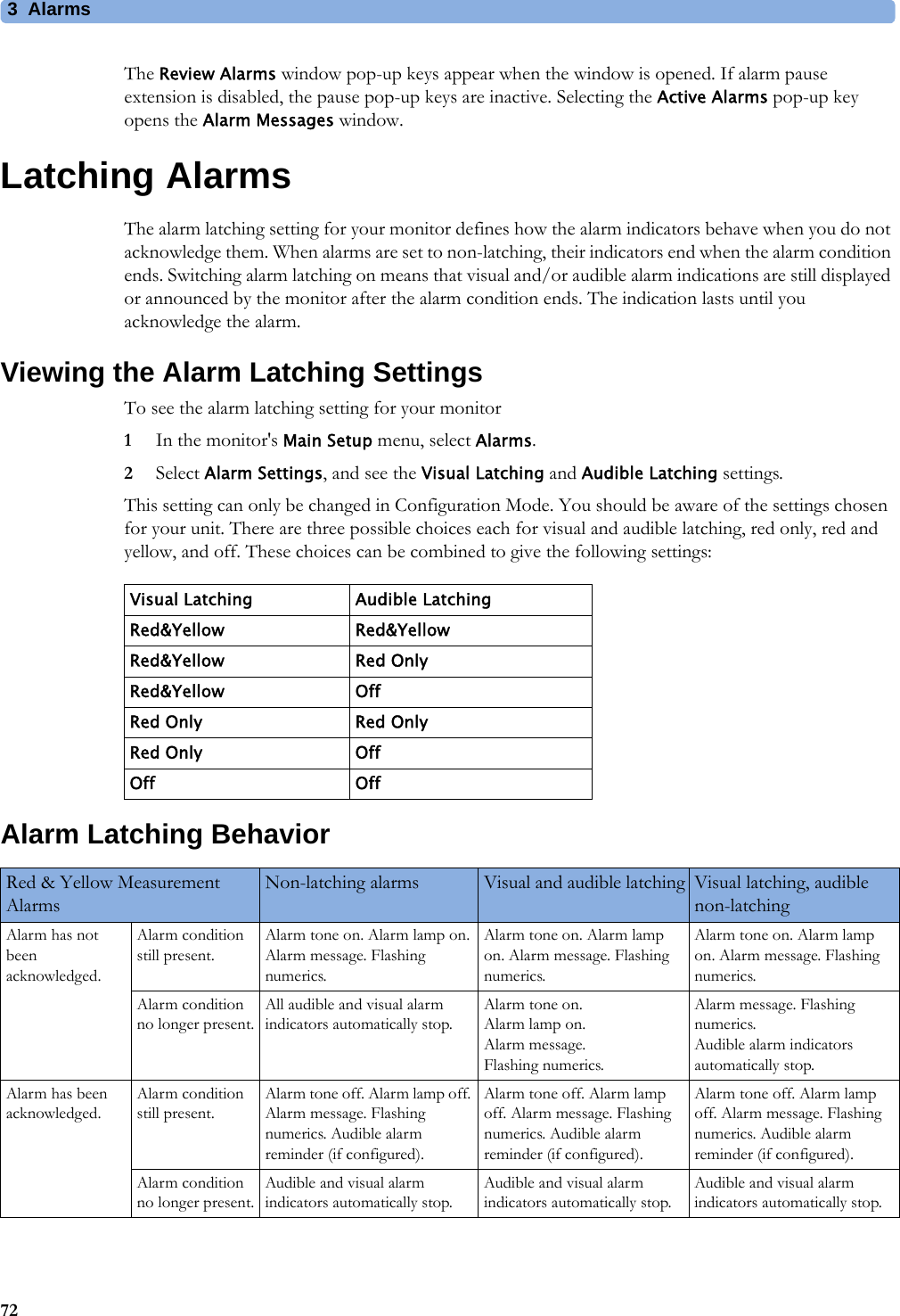
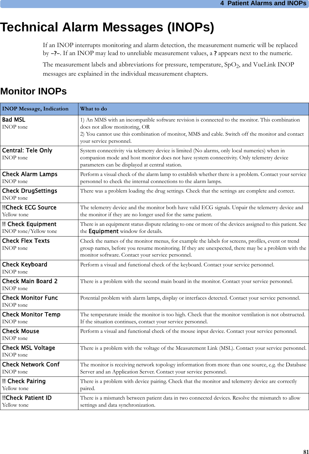
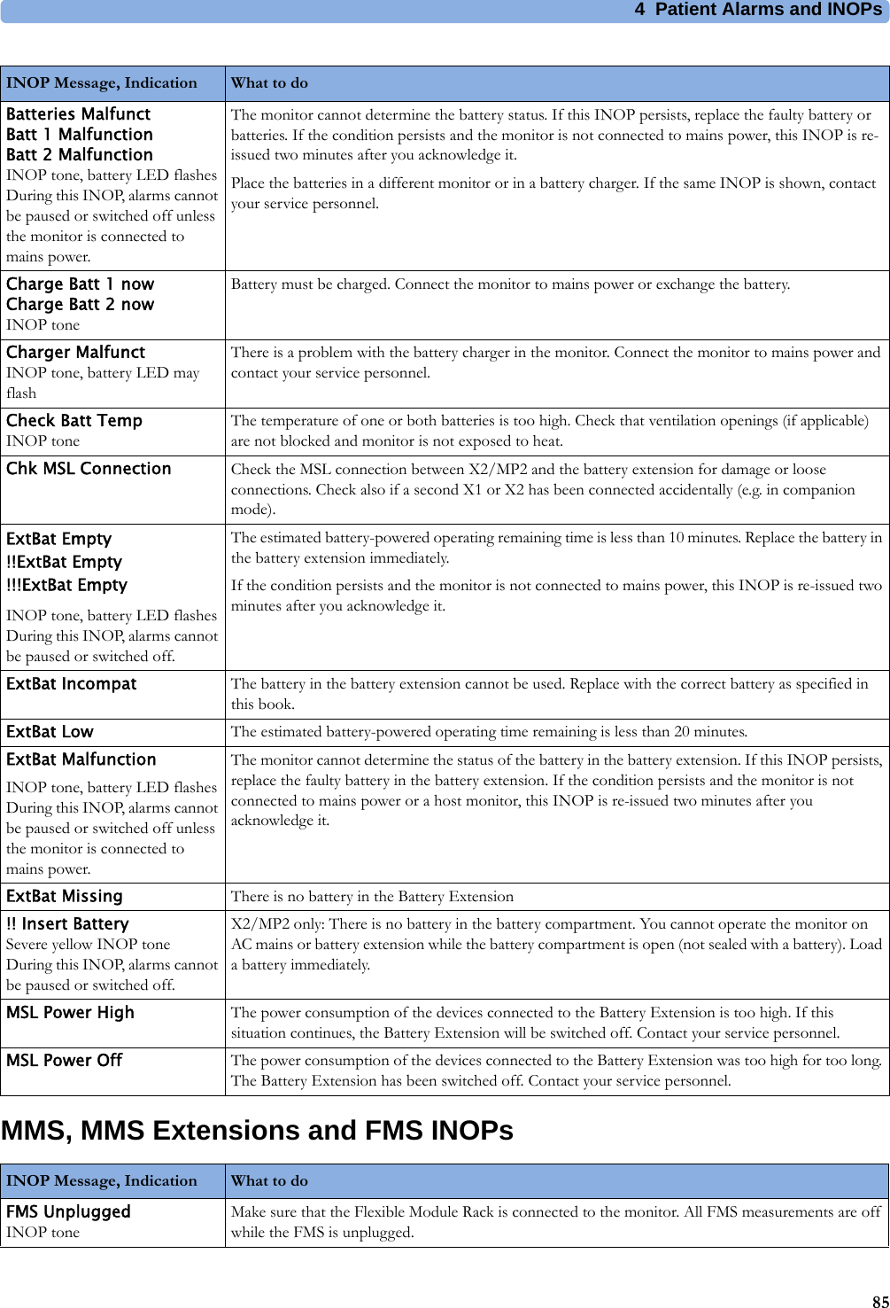
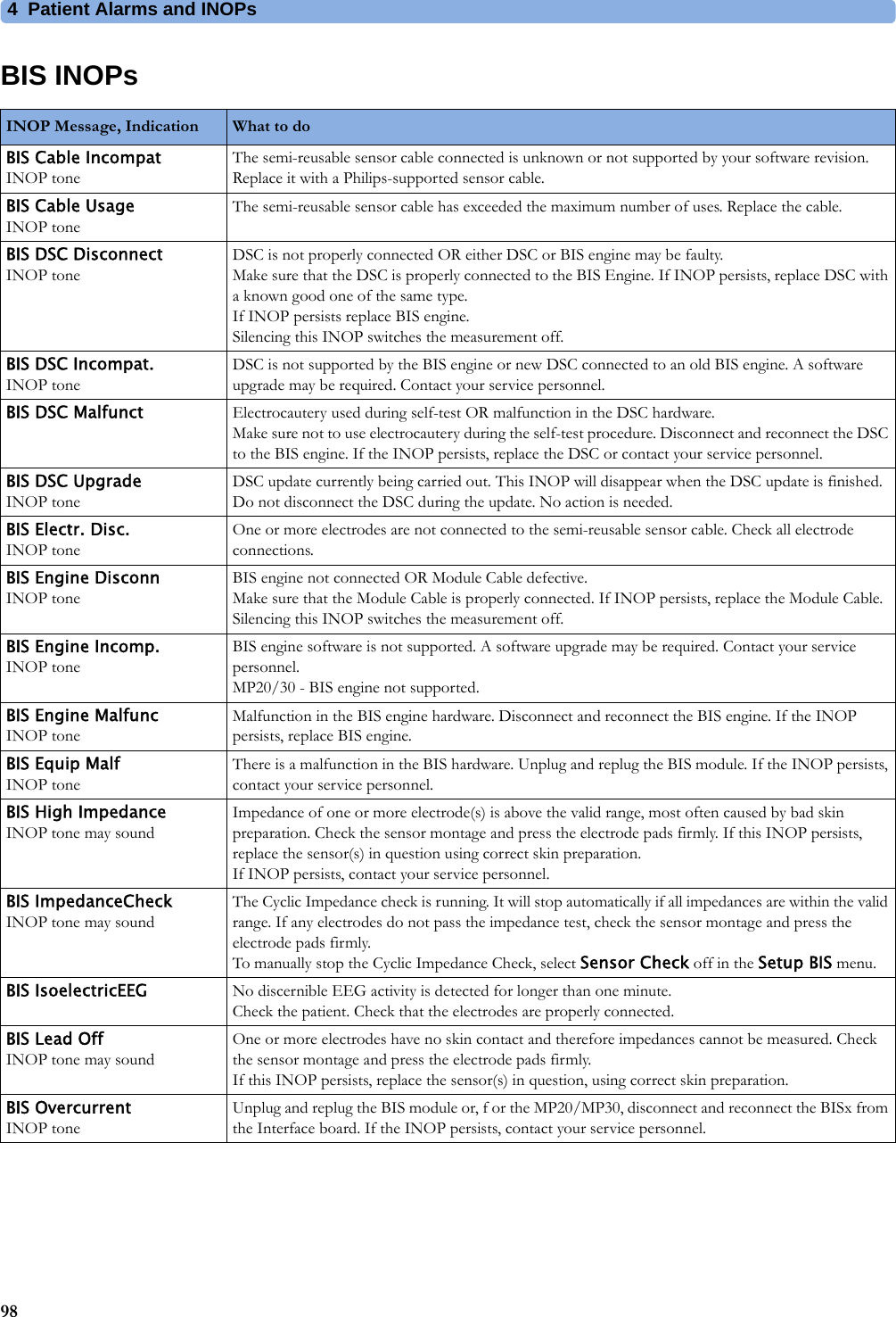
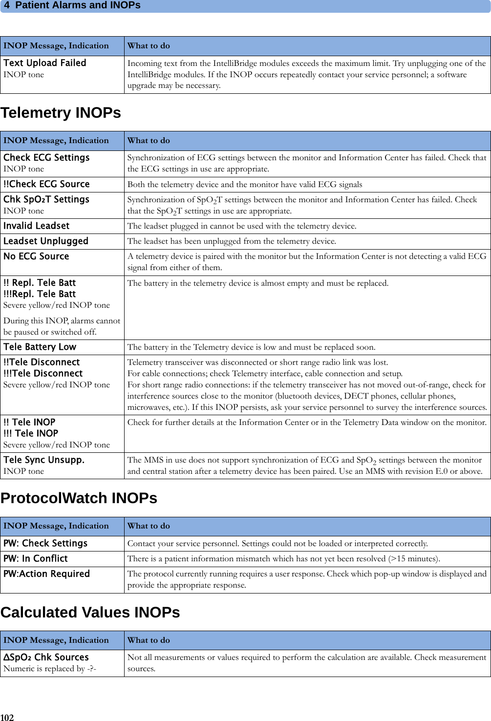
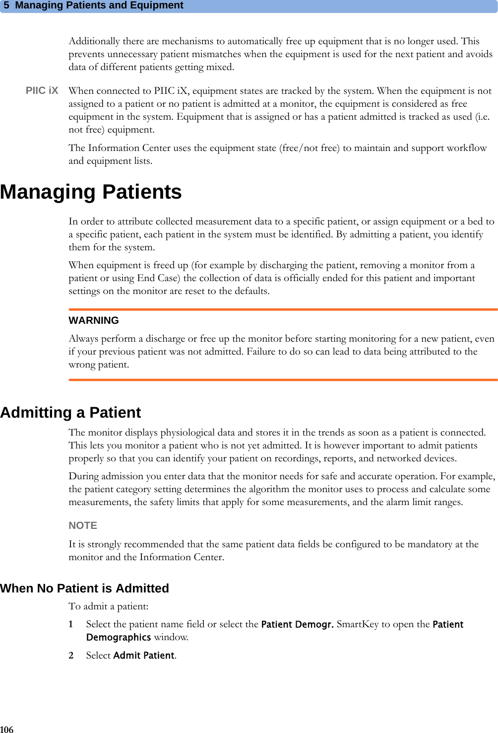
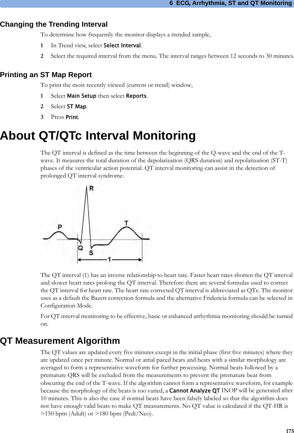
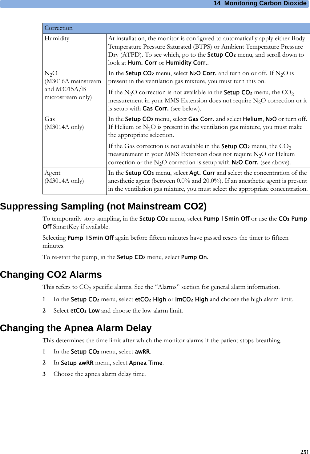
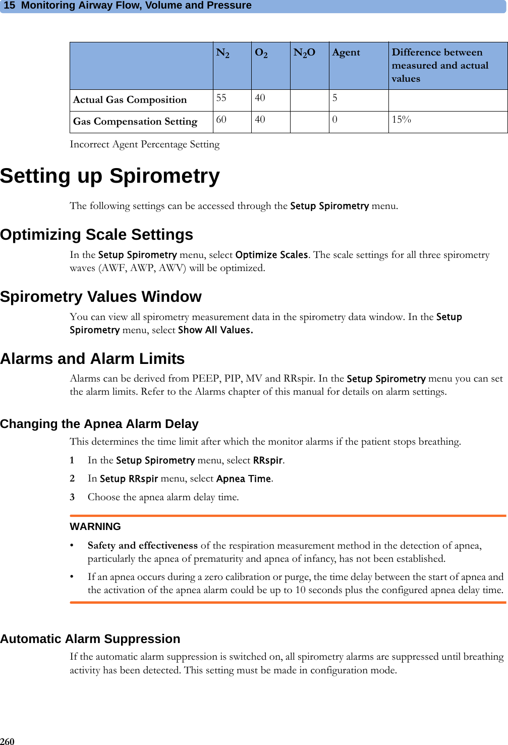
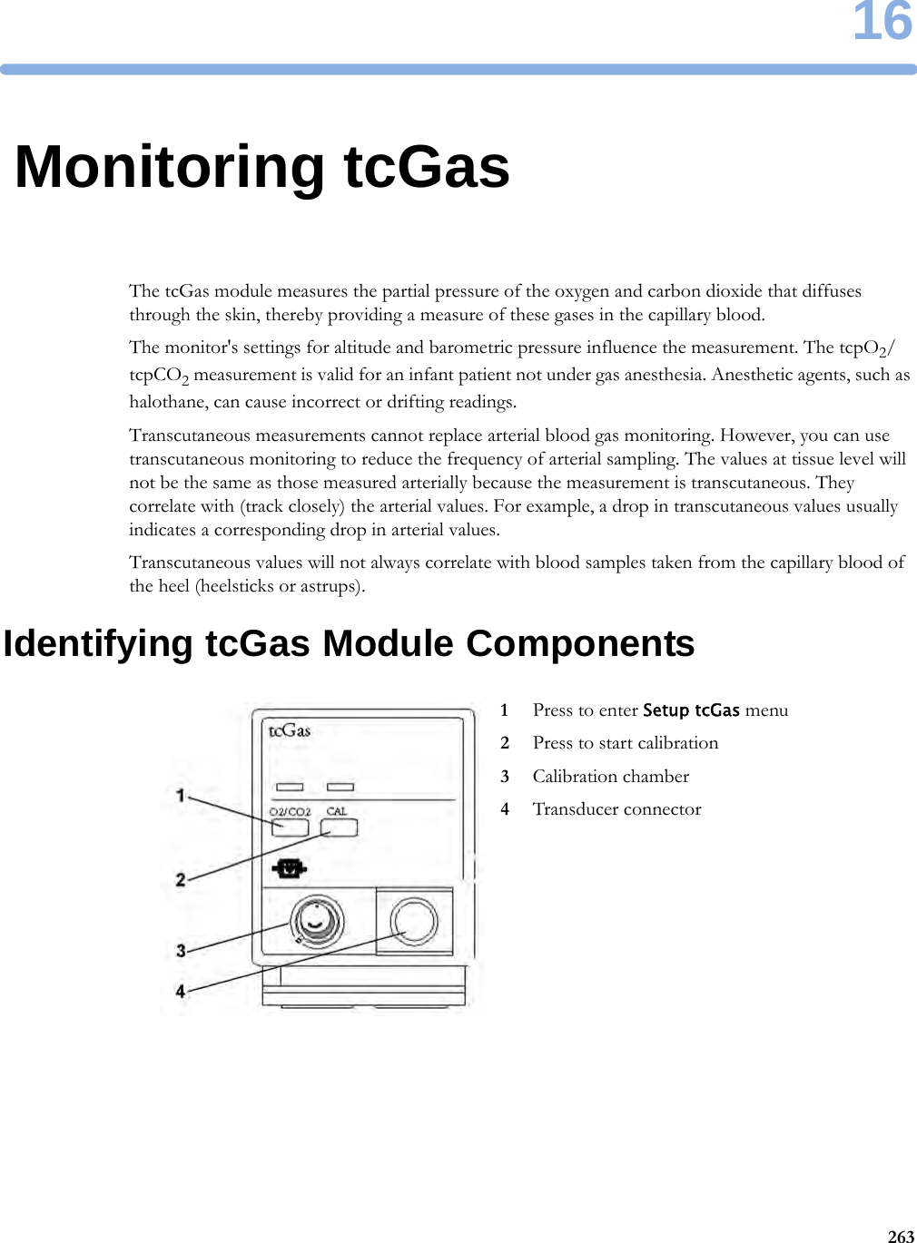
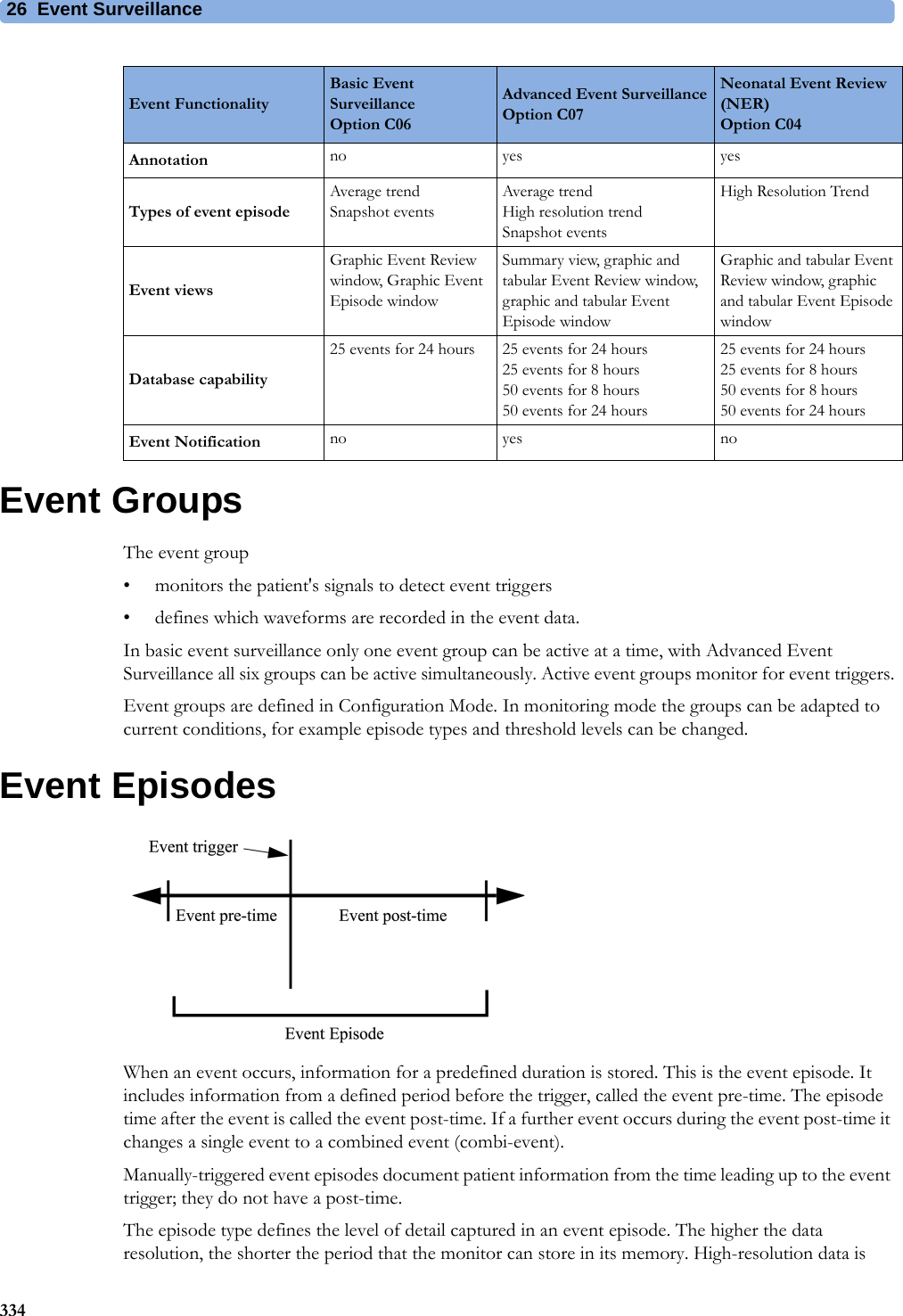
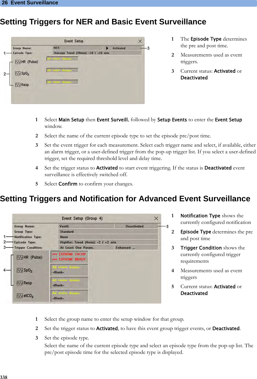
![4 Patient Alarms and INOPs97EEG INOPs<tcGas Label> Change SiteIf Heat Switch Off is configured to Yes, numeric is replaced by -?-INOP toneSite Timer has timed out. Change the application site to avoid skin burns. To reset the Site Timer, either calibrate and change the measurement site, or change the measurement site and reset the Site Timer manually by selecting the appropriate site time from the Setup tcGas menu.<tcGas Label> Check TimeSite Timer due to time out in 15 minutes or less.<tcGas Label> Equip MalfNumeric is replaced by -?-INOP toneThere is a malfunction in the transducer or module. Connect another transducer. If this INOP persists, contact your service personnel.<tcGas Label>NoTransducerNumeric is replaced by -?-INOP toneNo transducer is connected to the tcpO2/tcpCO2 module. Silencing the alarm switches off the measurement.<tcGas Label> StabilizingA ? appears next to the labelThe transducer has not yet reached the selected temperature and/or skin hyperemization is not yet finished. This INOP will disappear within three minutes.<tcGas Label> UnpluggedNumeric is replaced by -?-INOP toneThe measurement is switched on but the module is unplugged.The measurement automatically disappears from the display. Silencing this INOP switches off the measurement.INOP Message, Indication What to do INOP Message, Indication What to do EEG Equip MalfINOP toneThe EEG hardware is faulty. Contact your service personnel.EEG Impedance HighEEG1 ImpedanceHighEEG2 ImpedanceHighThe signal electrode in one or both channels exceeds the user-selected impedance limit, or the impedance of a single electrode exceeds the limit. Check the impedance. If the impedance is too high, reconnect the electrodes according to the EEG monitoring setup guidelines. If the INOP persists, contact your service personnel.EEG Line NoiseEEG1 Line NoiseEEG2 Line NoiseExcessive line noise has been detected in either channel EEG1 or EEG2, or in both EEG channels. Keep all cables together and away from metallic bodies, other cables & radiated fields.EEG Muscle NoiseEEG1Muscle NoiseEEG2Muscle NoiseToo much power above 30 Hz has been detected in channel EEG1 or EEG2, or both. Check the Electrode-to-Skin Impedance and reposition the electrode away from possible muscle activity, if necessary.EEG UnpluggedINOP tonePlug in module. Silencing this INOP switches off the measurement.EEG1 Lead Off <n>EEG2 Lead Off <n>[n = electrode]Reconnect specified electrode.EEG1 Lead OffEEG2 Lead Offat Information CenterOne or more electrodes are not connected. Check in the EEG Impedance / Montage window on the monitor which electrode(s) are affected and reconnect the electrodes.EEG1 Leads OffEEG2 Leads OffTwo or more electrodes are not connected. Check in the EEG Impedance / Montage window which electrodes are affected and reconnect the electrodes.EEG1 OverrangeEEG2 OverrangeInput signal is too high in one or both channels. This is usually caused by interfering signals such as line noise or electrosurgery.EEGNoTransducerINOP toneThe trunk cable is disconnected from the EEG plug-in module. Reconnect the trunk cable. Silencing this INOP switches the measurement off.](https://usermanual.wiki/Philips-Medical-Systems-North-America/SRRBV3/User-Guide-2121007-Page-97.png)
![5 Managing Patients and Equipment125The ECG measurement will be activated again at the monitor. [Note that in this case, as the screen switches back to the monitor's own measurements, the SpO2T measurement (if present) will no longer be displayed].In the same way the source is tracked when a telemetry device is directly connected to a monitor, then disconnected and vice versa.In case of ambiguity, a yellow INOP message !!Check ECG Source indicates that more than one valid ECG source is active.Synchronized SettingsFor some measurements, settings can be synchronized between the monitor and another measurement device. For example, if ECG is measured at the monitor, and then the patient is connected to a telemetry device for monitoring, the Information Center will use the monitor settings for the telemetry device. In general, the following settings will be synchronized:PIIC iX With the IntelliVue Information Center iX, the following additional measurement settings can be synchronized:Heart Rate HR/Pulse Alarm On/Off, Heart Rate High/Low Limit,ECG ECG On/Off1, Primary Lead, Secondary Lead, Va Lead2, Vb Lead2, Lead PlacementArrhythmia Analysis Mode, Arrhythmia On/Off, Asystole Threshold, Pause Threshold, VTach HR, VTach Run, PVCs/min, Vent. Rhythm, SVT HR, SVT Run, PVCs/min On/Off, Pacer not capture On/Off, Pacer not pace On/Off, Non-Sustain On/Off, Vent. Rhythm On/Off, Run PVCs On/Off, Pair PVCs On/Off, Missed Beat On/Off, Pause On/Off, R-on-T PVCs On/Off, Vent. Bigeminy On/Off, Vent. Trigeminy On/Off, Multiform PVCs On/Off, Irregular HR On/Off, SVT On/Off, Afib On/Off, Afib/IrrHR End Threshold, All ECG Alarm INOP mode.ST ST Analysis On/Off, ST Alarm On/Off, ISO Point, J point, ST point, ST Alarm Limits, ST-Index On/Off, ISO/J-Point Detection, ST Lead On/Off, ST BaselineQT QT analysis On/Off, QT Lead, QTc High Alarm On/Off, ΔQTc Alarm On/Off, QTc High Limit, ΔQTc High Limit, QT Baseline3SpO2TSpO2 Alarms on/off, SpO2 Alarm limits, SpO2 Low Alarm Delay, SpO2 High Alarm Limit, Desat Alarm LimitNBP Alarm Suppression On/Off, Pulse(SpO2) On/Off1ECG On/Off setting is forced to ON by the monitor, if the local setting is ON.2Va and Vb leads are reset to default (V2, V5) if the configured Va or Vb lead for the telemetry device is not one of V1 through V6.3With PIIC, QT baseline is synchronized, but not QT snippets.ECG/Arrhythmia Some ECG Alarms INOP On/OffST STE On/Off, STE Alarm On/OffNBP Sys/Dia/Mean Alarm Limits, Alarms On/ Off, Alarm SourceResp Apnea Time, Alarm Limits, Alarm On/Off, Resp On/Off](https://usermanual.wiki/Philips-Medical-Systems-North-America/SRRBV3/User-Guide-2121007-Page-125.png)


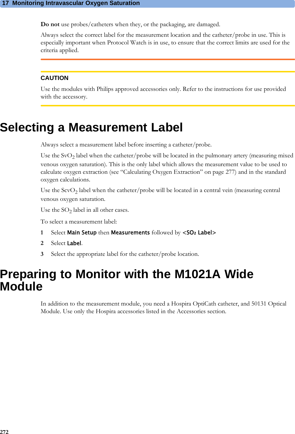
![17 Monitoring Intravascular Oxygen Saturation2774Draw a blood sample from the distal port of the catheter and flush the line according to standard hospital practice.5Obtain laboratory analysis of the sample using direct measurements.6Select CalibrationValue and select from the list the value received from the lab.7Select Hct [%] (or Hb [mmol/l] or Hb [g/dl] depending on the set up) and enter the corresponding value from the laboratory analysis.To change the setup for entering the Hb/Hct, see “Changing the Lab Value Required for Entry” on page 277 below.8If you need to enter a new correction factor, select Catheter Factor.9Enter the correction factor.10 Complete the calibration by selecting Store In-VivoCal (even if the stored calibration value did not change) and select Confirm. This updates the data stored in the optical module.Selecting Recall Last Cal recalls the previously stored calibration value.If the calibration fails, check that the light intensity indicator is indicating a stable medium to high level. Repeat the calibration.Changing the Lab Value Required for EntryYou can change the lab value required to be entered: Hb [g/dl], Hb [mmol/l] or Hct [%].1In the Setup <SO₂ Label> menu, select Hb/Hct Entry.2Select your preferred lab value and unit.Further Information for Both ModulesChecking Suspicious ValuesIf you have any doubts about the correctness of the measurement value, take a blood sample and have it analyzed using standard laboratory procedures.Calculating Oxygen ExtractionOxygen extraction is the difference between the measured SpO2 and SvO2 values. If you are monitoring SpO2 and SvO2, the monitor can calculate this value and display it as a numeric.• To switch oxygen extraction calculation on or off, in the Setup Sp-vO₂ menu, select Sp-vO₂ and toggle between On and Off.•If more than one SpO2 value is available, you must choose which value is used in the calculation. In the Setup Sp-vO₂ menu, select SpO₂ Source and select the required source.If one of the calculation sources becomes unavailable, the monitor displays the INOP Sp-vO₂ Chk Sources for one minute. After this time, the calculation automatically switches off. If the missing source becomes available again, the calculation automatically switches on again.](https://usermanual.wiki/Philips-Medical-Systems-North-America/SRRBV3/User-Guide-2121007-Page-277.png)


![24 Calculations328Entering Values for CalculationsThe monitor automatically enters any available values for calculations. For aperiodically-measured values such as C.O., the monitor will re-use the most recent value in the calculation database until a new value becomes available. If the calculation time is the last C.O. time, values will be used from up to and including 30 minutes before the C.O. time, except for height and weight where the last available value will be used.• To enter calculations values manually or edit automatically-entered values, select the value field to open the on-screen keyboard and use this to enter the correct value. Values edited manually are marked with an asterisk (*).If you enter a value that has more decimal places than allowed for a particular input, the value you enter will be rounded off after you select Enter. If you enter a value which cannot be stored, the message Value out of range will appear. Enter a new value.In hemodynamic calculations, if the systolic and diastolic pressures are manually entered, the mean pressure is calculated and marked with an asterisk (*). The formula used to estimate the mean pressure is:[systolic + (diastolic x 2)] / 3.Automatic Value SubstitutionIf the monitor cannot find a value required for calculation, it automatically tries to find an equivalent source for this value. For example, if C.O. is required but unavailable, the monitor automatically looks for CCO as a alternative source of C.O. values, or an alternative Pressure label may be used instead of ABP. The label of the value in the Calculations window does not change. Substituted values are marked with an asterisk (*).If a PAWP value is not available, PAWP will be set to zero in the formulas where it is used.Automatic Unit ConversionThe monitor needs consistent units for performing calculations. It automatically converts units where necessary before it performs the calculation, for example, pressures sourced in kPa, cmH2O, or mbar are automatically converted to mmHg, or to cmH2O for ventilation calculations.Manual Unit ConversionIf you need to convert units for other purposes you can use the Unit Conversion window:1Select Main Setup then select Calculations.2Select Unit Conversion.3Select the field under the unit you know and use the on-screen keypad to enter the known value. The converted value automatically appears in the adjacent field.BSA FormulaYour monitor provides both the Boyd and Dubois formulas for the calculation of body surface area (BSA). For calculations, the monitor uses the setting defined in the Patient Demographics menu. All calculation results that use BSA are indexed to the selected formula.• To check the current setting, select the patient name to enter the Patient Demographics menu. BSA(B) indicates that the Boyd formula is used; BSA(D) indicates that the Dubois formula is used.](https://usermanual.wiki/Philips-Medical-Systems-North-America/SRRBV3/User-Guide-2121007-Page-328.png)

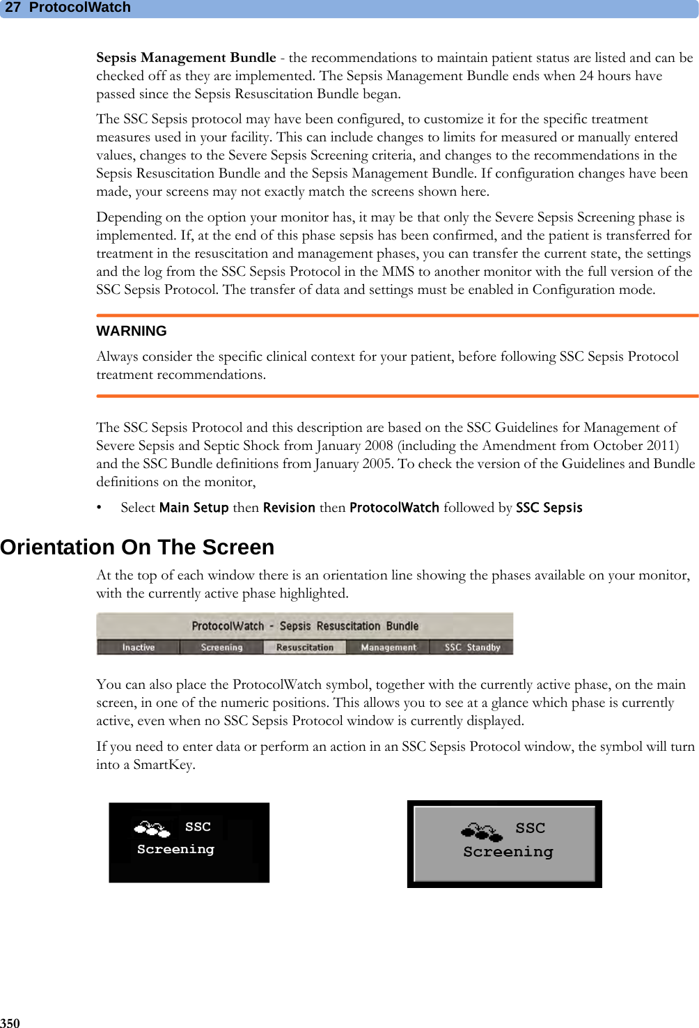
![2734927ProtocolWatchProtocolWatch (PW) is a clinical decision support tool. It allows you to run a clinical protocol which can monitor developments in the patient's condition, taking into account:• measured values from the monitor• values manually entered by you (for example manual temperature measurements, lab values)• your assessment of patient statusProtocolWatch notifies you when certain conditions or combinations of conditions occur and it documents developments in a log which can be printed.SSC Sepsis ProtocolThe SSC (Surviving Sepsis Campaign) Sepsis Protocol is a protocol implemented for the ProtocolWatch application. The SSC Sepsis Protocol is for use in screening for severe sepsis and monitoring of its treatment. It is a computerized implementation of the January 2008 Surviving Sepsis Campaign Guidelines for Management of Severe Sepsis and Septic Shock [Dellinger RP, Levy MM, Carlet JM et al: Surviving Sepsis Campaign: International guidelines for management of severe sepsis and septic shock: 2008 (published correction appears in Crit Care Med; 36:1394-1396). Crit Care Med 2008 36:296-327.], including the Amendment from October 2011. Philips does not make any claims about their effectiveness to reduce the morbidity or mortality associated with severe sepsis.The SSC Sepsis Protocol assists you in recognizing the early signs and symptoms of sepsis by comparing the state of your patient to the defined criteria and then guides you through the recommended treatment protocol. Use of the SSC Sepsis Protocol requires thorough knowledge of the complete SSC Guidelines for Management of Severe Sepsis and Septic Shock. Due to space limitations on the screen, the recommendations cannot always be reproduced in the full detail available in the printed and on-line guidelines. The SSC Sepsis Protocol is not a diagnostic or therapeutic tool and is not intended to replace the competent judgment of a clinician.The SSC Sepsis Protocol consists of three separate consecutive phases:Severe Sepsis Screening - measurement values and patient status are compared to the Severe Sepsis Screening criteria. When these criteria have been met, the clinician confirms the presence of infection and sepsis-related organ dysfunction and can authorize entering the Sepsis Resuscitation Bundle.Sepsis Resuscitation Bundle - the recommendations for sepsis resuscitation are listed and can be checked off as they are implemented. After achievement of all the sepsis resuscitation goals, or at the latest after 6 hours, the Sepsis Resuscitation Bundle is completed and the Sepsis Management Bundle begins.](https://usermanual.wiki/Philips-Medical-Systems-North-America/SRRBV3/User-Guide-2121007-Page-349.png)


![40 Specifications470Interface SpecificationsMX400/450/500/550/600/700/800 Interface SpecificationsMX400/450/500/550/600/700/800Network Standard 100-Base-TX (IEEE 802.3 Clause 25)Connector RJ45 (8 pin)Isolation basic insulation (reference voltage: 250 V; test voltage: 1500 V)MIB/RS232 Standard IEEE 1073-3.2-2000Connectors RJ45 (8 pin)Mode Software-controllableBCC (RxD/TxD cross over) orDCC (RxD/TxD straight through) not available for the advanced system interface MX400/450/500/550Power 5 V ±5 %, 100 mA (max.)Isolation basic insulation (reference voltage: 250 V; test voltage: 1500 V)USB Interface Standard USB 2.0 full-speed (embedded host)Connector USB series "Standard A" receptaclePower Low power port 4.4V min; max. load for all ports together 500 mAIsolation noneRS232 (Standard) Connector RJ45 (8-pin)Power noneIsolation basic insulation (reference voltage: 250 V; test voltage: 1500 V)RS232 (Independent display interface option)Connector RJ45 (8-pin)Power noneIsolation noneBasic Nurse Call Relay Connector modular Jack 6P6C, active open and closed contactContact <=100 mA, <=24 V DCIsolation basic insulation (reference voltage: 250 V; test voltage: 1500 V)Delay <[Configured Latency +0.5] secFlexible Nurse Call Relay Connector 20 pin MDR (Mini D-Ribbon), active open and closed contactsContact <=100 mA, <=24 V DCIsolation basic insulation (reference voltage: 250 V; test voltage: 1500 V)Delay <[Configured Latency +0.5] secIntelliBridge EC10 Interface boardConnector RJ45 (8-pin)Speed 1200 Bd, 2400 Bd, 4800 Bd, 9600 Bd, 19200 Bd, 38400 Bd, 57600 Bd, or 115200 Bd signaling speedCharacter bits 5-8Stop bits 1 or 2Parity Even or odd parity generation and checkingPower 5 V±5 % @ 0-100 mAIsolation double insulation (reference voltage: 250 V; test voltage: 4000 V)](https://usermanual.wiki/Philips-Medical-Systems-North-America/SRRBV3/User-Guide-2121007-Page-470.png)
![40 Specifications472Video Interface (Independent display interface option)Connector DVI (digital and analog, single link)Pixel clock frequency 31.5 MHz - 119 MHzDigital video signals single link TMDSAnalog video signals 0.7 Vpp@75 ΩHSYNC/VSYNC signals TTLDDC signals noneDDC power 5 V +/-5% @0-55 mAECG Sync Output/Analog ECG Output (1/4" stereo phone jack with tip, ring, sleeve)General Connector 1/4" phone with tip, ring, sleeveIsolation functional isolationAnalog ECG Output(ring, tip)Full scale on display signal gain x measured ECG voltageGain error <15 %Baseline offset <100 mVBandwidth 1 to 100 HzOutput voltage swing ±4 V (min)Signal delay <22 msSignal delay with older versions of the M3001A MMS[identifiable with the serial number prefix DE227 or DE441 and option string #A01]<30 msPacemaker Pulse filtered and included in ECG output signalDigital Pulse Output (ring) Output low voltage level <0.4 V @ I=-1 mAOutput high voltage level >2.4 V @ I=1 mAPulse Width 100 ms±10 ms (active high)Pulse Rise Time <1 ms (from 0.4 V to 2.4 V)Signal delay <25ms per AAMI EC13Signal delay with older versions of the M3001A MMS[identifiable with the serial number prefix DE227 or DE441 and option string #A01]<35ms per AAMI EC13MX400/450/500/550/600/700/800](https://usermanual.wiki/Philips-Medical-Systems-North-America/SRRBV3/User-Guide-2121007-Page-472.png)
![40 Specifications478RespirationHeart Rate Averaging Method Three different methods are used:Normally, heart rate is computed by averaging the 12 most recent RR intervals.For runs of PVCs, up to 8 RR intervals are averaged to compute the HR.If each of 3 consecutive RR intervals is greater than 1200 ms (that is, rate less than 50 bpm), then the 4 most recent RR intervals are aver\-aged to compute the HR.Response Time of Heart Rate Meter to Change in Heart Rate HR change from 80 to 120 bpm:Range: [6.4 to 7.2 seconds] Average: 6.8 secondsHR change from 80 to 40 bpm:Range: [5.6 to 6.4 sec] Average: 6.0 secondsHeart Rate Meter Accuracy and Response to Irregular Rhythm Ventricular bigeminy: 80 bpmSlow alternating ventricular bigeminy: 60 bpmRapid alternating ventricular bigeminy: 120 bpmBidirectional systoles: 90 bpmAccuracy of Input Signal Reproduction Methods A and D were used to establish overall system error and frequency response.Pacemaker Pulse Rejection Performance Rejection of pacemaker pulses with amplitudes from ±2 mV to ±700 mV and widths from 0.1 ms to 2.0 ms (Method A)Pacemaker Pulse Rejection of fast ECG signals 2.2 V/s RTI (Paced Mode)Minimum input slew rate 2.2 V/s RTIECG/Arrhythmia/ST Supplemental Information as required by AAMI EC11/13, IEC 60601-2-27Respiration Performance SpecificationsRespiration Rate Range Adult/pedi: 0 to 120 rpmNeo: 0 to 170 rpmAccuracy at 0 to 120 rpm ±1 rpmat 120 to 170 rpm ±2 rpmResolution 1 rpmBandwidth 0.3 to 2.5 Hz (-6 dB)Noise Less than 25 mΩ (rms) referred to the inputRespiration Alarm Specifications Range Adjustment DelayHigh Adult/pedi: 10 to 100 rpmNeo: 30 to 150 rpmunder 20 rpm: 1 rpm stepsover 20 rpm: 5 rpm stepsmax. 14 secondsLow Adult/pedi: 0 to 95 rpmNeo: 0 to 145 rpmunder 20 rpm: 1 rpm stepsover 20 rpm: 5 rpm stepsfor limits from 0 to 20 rpm: max. 4 secondsfor limits above 20 rpm: max. 14 secondsApnea Alarm 10 to 40 seconds 5 second steps](https://usermanual.wiki/Philips-Medical-Systems-North-America/SRRBV3/User-Guide-2121007-Page-478.png)

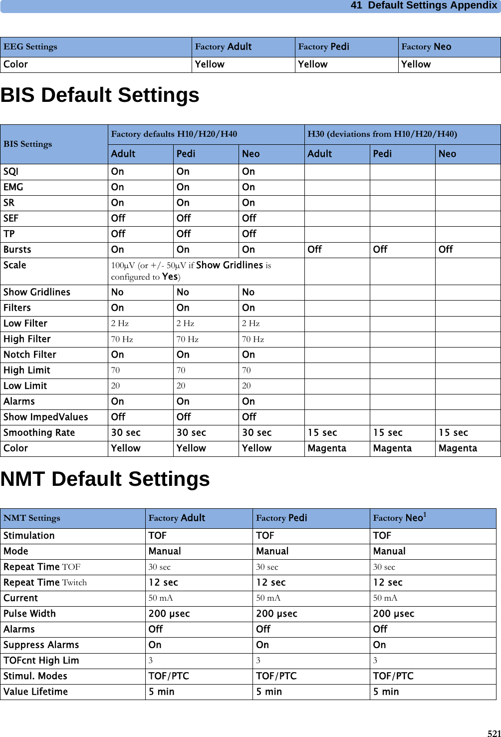
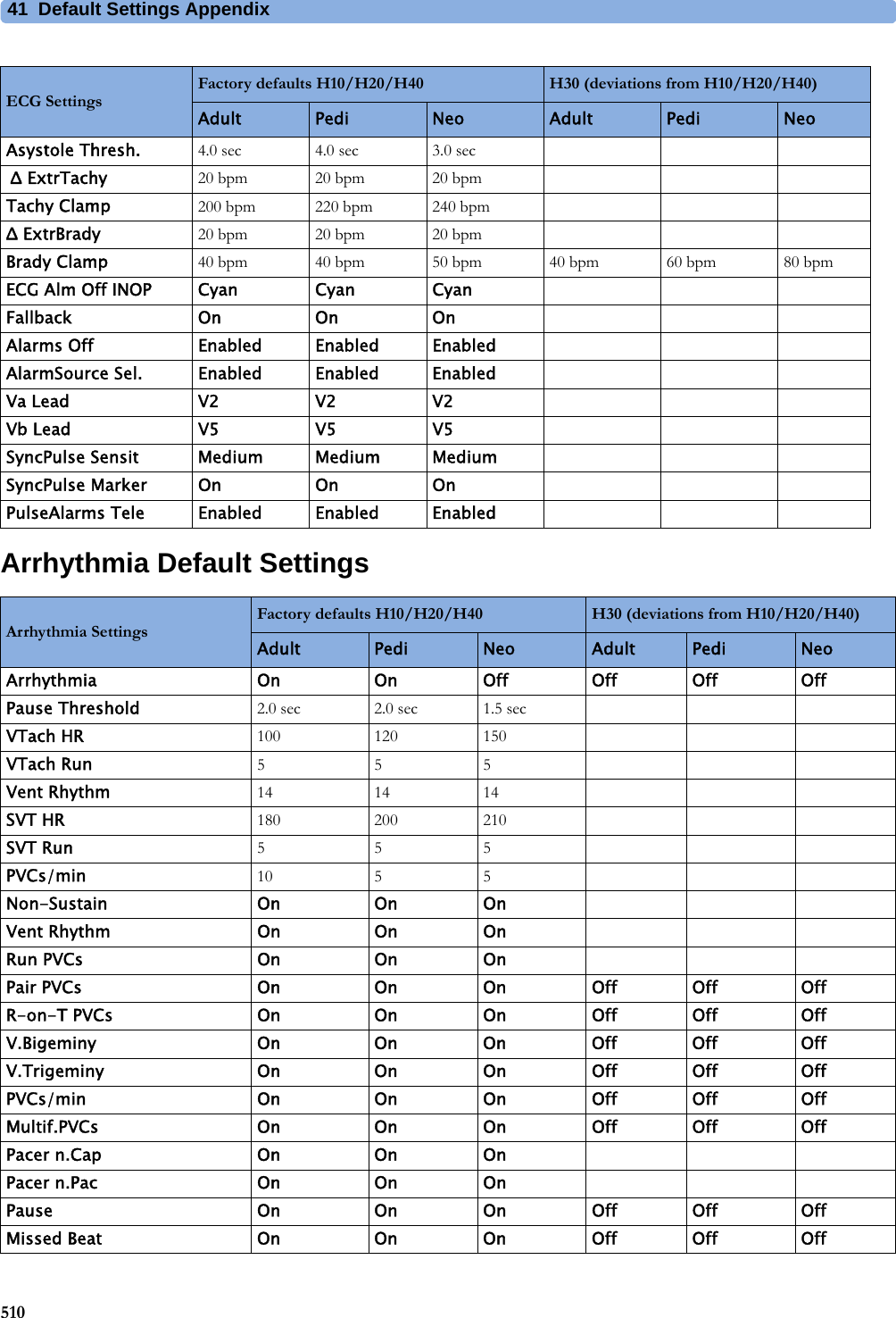
![4150141Default Settings AppendixThis appendix documents the most important default settings of your monitor as it is delivered from the factory. For a comprehensive list and explanation of default settings, see the Configuration Guide supplied with your monitor. The monitor's default settings can be permanently changed in Configuration Mode.Note: If your monitor has been ordered pre-configured to your requirements, the settings at delivery will be different from those listed here.Country-Specific Default SettingsCertain default settings are specific to a particular country. These are listed here for all countries alphabetically.Country-Description Line Frequency50/60 [Hz]UnitsWeightkg, lbUnitsHeightin, cmECG Cable ColorIEC, AAMIAfghanistan 50 kg cm AAMIÅland Islands 50 kg cm IECAlbania 50 kg cm IECAlgeria 50 kg cm IECAmerican Samoa 60 lb in AAMIAndorra 60 lb in AAMIAngola 50 kg cm IECAnguilla 60 lb in AAMIAntarctica 60 lb in AAMIAntigua and Barbuda 50 kg cm AAMIArgentina 50 kg cm AAMIArmenia 50 kg cm IECAruba 60 kg cm AAMIAustralia 50 kg cm AAMIAustria 50 kg cm IECAzerbaijan 50 kg cm IEC](https://usermanual.wiki/Philips-Medical-Systems-North-America/SRRBV3/User-Guide-2121007-Page-501.png)
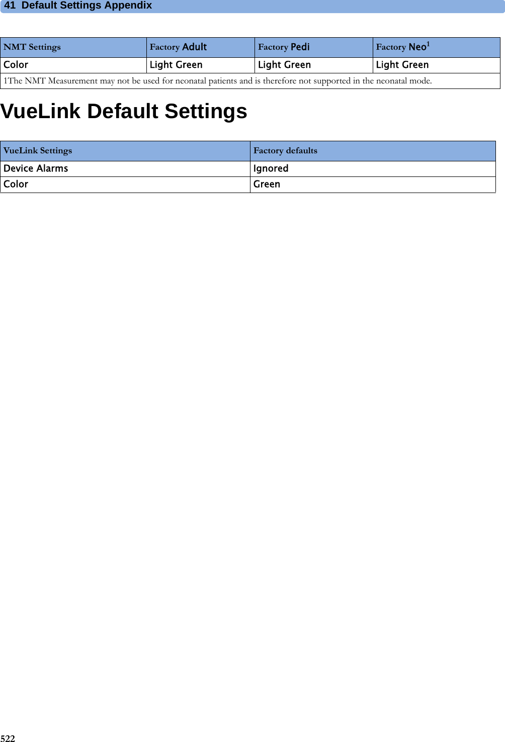
![41 Default Settings Appendix502Bahamas 60 kg cm AAMIBahrain 50 kg cm AAMIBangladesh 50 kg cm IECBarbados 50 kg cm AAMIBelarus 50 kg cm IECBelgium 50 kg cm IECBelize 60 lb in AAMIBenin 60 lb in AAMIBermuda 60 kg cm AAMIBhutan 60 lb in AAMIBolivia 60 kg cm AAMIBosnia and Herzegovina 50 kg cm IECBotswana 50 kg cm IECBouvet Island 60 lb in AAMIBrazil 60 kg cm AAMIBritish Indian Ocean Territory 60 lb in AAMIBrunei Darussalam 50 kg cm IECBulgaria 50 kg cm IECBurkina Faso 50 kg cm IECBurundi 50 kg cm IECCambodia 50 kg cm IECCameroon 50 kg cm IECCanada 60 kg cm AAMICape Verde 60 lb in AAMICayman Islands 60 kg cm AAMICentral African Republic 50 kg cm IECChad 60 lb in AAMIChile 50 kg cm AAMIChina 50 kg cm AAMIChristmas Islands 60 lb in AAMICocos Keeling Islands 60 lb in AAMIColombia 60 kg cm AAMIComoros 60 lb in AAMICongo 50 kg cm IECCongo, The Democratic Republic of the50 kg cm IECCountry-Description Line Frequency50/60 [Hz]UnitsWeightkg, lbUnitsHeightin, cmECG Cable ColorIEC, AAMI](https://usermanual.wiki/Philips-Medical-Systems-North-America/SRRBV3/User-Guide-2121007-Page-502.png)
![41 Default Settings Appendix503Cook Islands 60 lb in AAMICosta Rica 60 kg cm AAMICôte d'Ivoire 50 kg cm IECCroatia 50 kg cm IECCuba 60 kg cm IECCyprus 50 kg cm IECCzech Republic 50 kg cm IECDenmark 50 kg cm IECDjibouti 50 kg cm IECDominica 50 kg cm AAMIDominican Republic 60 kg cm AAMIEcuador 60 kg cm AAMIEgypt 50 kg cm IECEl Salvador 60 kg cm AAMIEquatorial Guinea 50 kg cm IECEritrea 50 kg cm IECEstonia 50 kg cm IECEthiopia 50 kg cm IECFalkland Islands, Malvinas 60 lb in AAMIFaroe Islands 60 lb in AAMIFiji 60 lb in AAMIFinland 50 kg cm IECFrance 50 kg cm IECFrench Guiana 50 kg cm IECFrench Polynesia 60 lb in AAMIFrench Southern Territories 60 lb in AAMIGabon 50 kg cm IECGambia 50 kg cm IECGeorgia 60 lb in AAMIGermany 50 kg cm IECGhana 50 kg cm IECGibraltar 60 lb in AAMIGreece 50 kg cm IECGreenland 60 lb in AAMIGrenada 50 kg cm AAMIGuadeloupe 50 kg cm IECCountry-Description Line Frequency50/60 [Hz]UnitsWeightkg, lbUnitsHeightin, cmECG Cable ColorIEC, AAMI](https://usermanual.wiki/Philips-Medical-Systems-North-America/SRRBV3/User-Guide-2121007-Page-503.png)
![41 Default Settings Appendix504Guam 60 lb in AAMIGuatemala 60 kg cm AAMIGuernsey 50 kg cm IECGuinea 60 lb in AAMIGuinea-Bissau 60 lb in AAMIGuyana 60 kg cm AAMIHaiti 60 kg cm AAMIHeard Island and McDonald Islands60 lb in AAMIHoly See, Vatican City State 60 lb in AAMIHonduras 60 kg cm AAMIHong Kong 50 kg cm IECHungary 50 kg cm IECIceland 50 kg cm IECIndia 50 kg cm IECIndonesia 50 kg cm IECIran, Islamic Republic of 50 kg cm AAMIIraq 50 kg cm AAMIIreland 50 kg cm IECIsle of Man 50 kg cm IECIsrael 50 kg cm IECItaly 50 kg cm IECJamaica 50 kg cm AAMIJapan 50 kg cm IECJersey 50 kg cm IECJordan 50 kg cm AAMIKazakhstan 50 kg cm IECKenya 50 kg cm IECKiribati 60 lb in AAMIKorea, Democratic People's Republic of60 lb in AAMIKorea, Republic of 60 kg cm AAMIKuwait 50 kg cm AAMIKyrgyzstan 60 lb in AAMILao People's Democratic Republic50 kg cm IECLatvia 50 kg cm IECCountry-Description Line Frequency50/60 [Hz]UnitsWeightkg, lbUnitsHeightin, cmECG Cable ColorIEC, AAMI](https://usermanual.wiki/Philips-Medical-Systems-North-America/SRRBV3/User-Guide-2121007-Page-504.png)
![41 Default Settings Appendix505Lebanon 50 kg cm AAMILesotho 50 kg cm IECLiberia 50 kg cm IECLibyan Arab Jamahiriya 60 lb in AAMILiechtenstein 60 lb in AAMILithuania 50 kg cm IECLuxembourg 50 kg cm IECMacao 50 kg cm IECMacedonia, The former Yugoslavian Republic of50 kg cm IECMadagascar 50 kg cm IECMalawi 50 kg cm IECMalaysia 50 kg cm IECMaldives 60 lb in AAMIMali 50 kg cm IECMalta 50 kg cm IECMarshall Islands 60 lb in AAMIMartinique 60 kg cm IECMauritania 50 kg cm IECMauritius 60 lb in AAMIMayotte 60 lb in AAMIMexico 60 kg cm AAMIMicronesia, Federal States of 60 lb in AAMIMoldova, Republic of 60 lb in AAMIMonaco 60 lb in AAMIMongolia 60 lb in AAMIMontenegro 50 kg cm IECMontserrat 50 kg cm AAMIMorocco 50 kg cm IECMozambique 50 kg cm IECMyanmar 60 lb in AAMINamibia 50 kg cm IECNauru 60 lb in AAMINepal 50 kg cm IECNetherlands 50 kg cm IECNetherlands Antilles 50 kg cm AAMICountry-Description Line Frequency50/60 [Hz]UnitsWeightkg, lbUnitsHeightin, cmECG Cable ColorIEC, AAMI](https://usermanual.wiki/Philips-Medical-Systems-North-America/SRRBV3/User-Guide-2121007-Page-505.png)
![41 Default Settings Appendix506New Caledonia 60 lb in AAMINew Zealand 50 kg cm AAMINicaragua 60 kg in AAMINiger 50 kg cm IECNigeria 50 kg cm IECNiue 60 lb in AAMINorfolk Islands 60 lb in AAMINorthern Mariana Islands 60 lb in AAMINorway 50 kg cm IECOman 50 kg cm AAMIPakistan 50 kg cm IECPalau 60 lb in AAMIPalestinian Territory 50 kg cm AAMIPanama 60 lb in AAMIPapua New Guinea 60 lb in AAMIParaguay 50 kg cm AAMIPeru 60 kg cm AAMIPhilippines 60 kg cm AAMIPitcairn 60 lb in AAMIPoland 50 kg cm IECPortugal 50 kg cm IECPuerto Rico 60 lb in AAMIQatar 50 kg cm AAMIReunion 60 lb in AAMIRomania 50 kg cm IECRussian Federation 50 kg cm IECRwanda 50 kg cm IECSaint Helena 60 lb in AAMISaint Kitts and Nevis 60 kg cm AAMISaint Lucia 50 kg cm AAMISaint Pierre and Miquelon 60 lb in AAMISaint Vincent & the Grenadines 50 kg cm AAMISamoa 60 lb in AAMISan Marino 60 lb in AAMISao Tome and Principe 60 lb in AAMISaudi Arabia 50 kg cm AAMICountry-Description Line Frequency50/60 [Hz]UnitsWeightkg, lbUnitsHeightin, cmECG Cable ColorIEC, AAMI](https://usermanual.wiki/Philips-Medical-Systems-North-America/SRRBV3/User-Guide-2121007-Page-506.png)
![41 Default Settings Appendix507Senegal 50 kg cm IECSerbia 50 kg cm IECSerbia & Montenegro 50 kg cm IECSeychelles 60 lb in AAMISierra Leone 50 kg cm IECSingapore 50 kg cm IECSlovakia 50 kg cm IECSlovenia 50 kg cm IECSolomon Islands 60 lb in AAMISomalia 50 kg cm IECSouth Africa 60 lb in AAMISouth Georgia and the South Sandwich Islands60 lb in AAMISpain 50 kg cm IECSri Lanka 50 kg cm IECSudan 50 kg cm IECSuriname 60 kg cm AAMISvalbard and Jan Mayen 60 lb in AAMISwaziland 60 lb in AAMISweden 50 kg cm IECSwitzerland 50 kg cm IECSyrian Arab Rep 50 kg cm AAMITaiwan, Province of China 60 kg cm AAMITajikistan 60 lb in AAMITanzania, United Republic of 60 lb in AAMIThailand 50 kg cm AAMITimor-Leste 60 lb in AAMITogo 60 lb in AAMITokelau 60 lb in AAMITonga 60 lb in AAMITrinidad and Tobago 60 kg cm AAMITunisia 50 kg cm IECTurkey 50 kg cm IECTurkmenistan 60 lb in AAMITurks and Caicos Islands 60 kg cm AAMITuvalu 60 lb in AAMICountry-Description Line Frequency50/60 [Hz]UnitsWeightkg, lbUnitsHeightin, cmECG Cable ColorIEC, AAMI](https://usermanual.wiki/Philips-Medical-Systems-North-America/SRRBV3/User-Guide-2121007-Page-507.png)
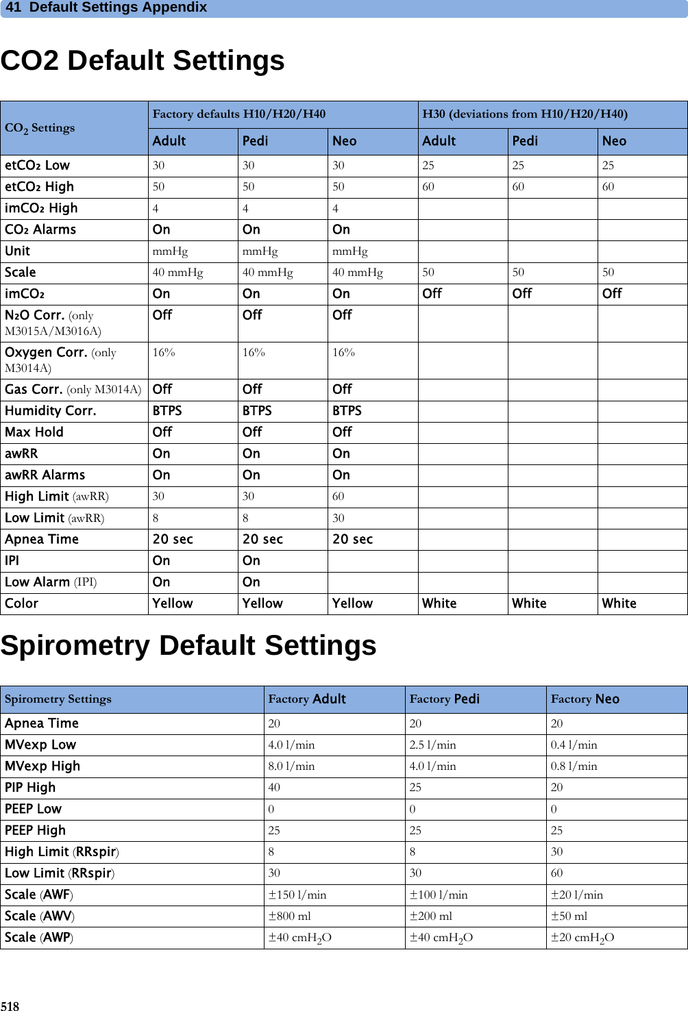
![41 Default Settings Appendix508Alarm and Measurement Default SettingsThe default wave speed for all measurements except Respiration is 25 mm/sec. For Respiration the default wave speed is 6.25 mm/sec.In the following tables, settings may be entered only once per table row if they are the same for all patient categories.Alarm Default SettingsUganda 60 lb in AAMIUkraine 60 lb in AAMIUnited Arab Emirates 50 kg cm AAMIUnited Kingdom 50 kg cm IECUnited States 60 lb in AAMIUnited States Minor Outlying Islands60 lb in AAMIUruguay 50 kg cm AAMIUzbekistan 60 lb in AAMIVanuatu 60 lb in AAMIVenezuela 60 lb in AAMIViet Nam 50 kg cm IECVirgin Islands, British 50 kg cm AAMIVirgin Islands, United States 60 lb in AAMIWallis and Futuna Islands 60 lb in AAMIWestern Sahara 50 kg cm IECYemen 50 kg cm AAMIZambia 60 lb in AAMIZimbabwe 60 lb in AAMICountry-Description Line Frequency50/60 [Hz]UnitsWeightkg, lbUnitsHeightin, cmECG Cable ColorIEC, AAMIAlarm Settings Factory Default H10/H20/H40 H30 (deviations from H10/H20/H40)Alarm Volume 5Alarms Off 2 minPause Al. 5min EnabledPause Al. 10min EnabledAuto Alarms Off OffAlarmOffReminder OffVisual Latching Red&Yellow Red Only](https://usermanual.wiki/Philips-Medical-Systems-North-America/SRRBV3/User-Guide-2121007-Page-508.png)
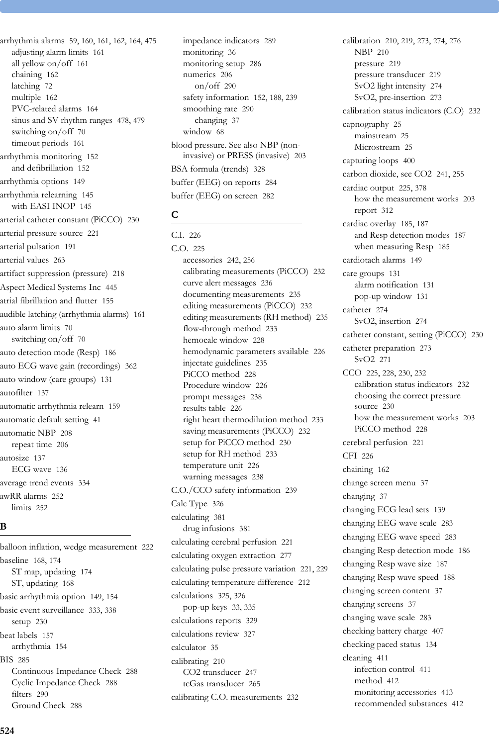
![41 Default Settings Appendix519tcGas Default SettingsIntravascular Oxygen Saturation Default SettingstcGas Settings Factory Adult Factory Pedi Factory NeotcpO₂ High Limit 80 mmHg 80 mmHg 80 mmHgtcpO₂ Low Limit 50 mmHg 50 mmHg 50 mmHgtcpO₂ Alarms On On OntcpCO₂ HighLimit 50 mmHg 50 mmHg 50 mmHgtcpCO₂ Low Limit 30 mmHg 30 mmHg 30 mmHgtcpCO₂ Alarms On On OnSite Timer 4.0 hours 4.0 hours 4.0 hoursDisable Timer Not Allowed Not Allowed Not AllowedHeat Switch Off (i.e., after Site Timer elapsed) No No NoTransducer Temp. 43.0°C 43.0°C 43.0°CCO₂ Correction (Severinghaus) On On OnMetabolismFactor 8 mmHg 8 mmHg 8 mmHgtcGas Unit mmHg mmHg mmHgTemperature Unit °C °C °CtcpO₂ Color Blue Blue BluetcpCO₂ Color Green Green GreenSO2 Settings Factory Adult Factory Pedi Factory NeoLow Limit 70% 70% 70%HR High Limit 80% 80% 80%Alarms On On OnLight Intensity On On OnColor Yellow Yellow YellowHb/Hct Entry Hct [%] Hct [%] Hct [%]Factor Entry Disabled Disabled DisabledSvO2 Settings Factory Adult Factory Pedi Factory NeoLow Limit 60% 60% 60%High Limit 80% 80% 80%Alarms On On OnLight Intensity On On OnColor Yellow Yellow YellowHb/Hct Entry Hct [%]Factor Entry Disabled](https://usermanual.wiki/Philips-Medical-Systems-North-America/SRRBV3/User-Guide-2121007-Page-519.png)
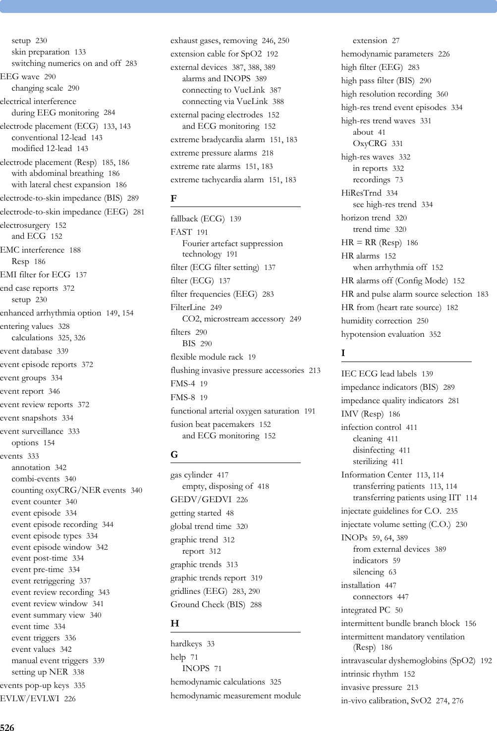
![41 Default Settings Appendix520SvO2 Default SettingsScvO2 Default SettingsEEG Default SettingsScvO2 Settings Factory Adult Factory Pedi Factory NeoLow Limit 70% 70% 70%High Limit 80% 80% 80%Alarms On On OnLight Intensity On On OnColor Yellow Yellow YellowSvO2 Settings Factory Adult Factory Pedi Factory NeoLow Limit 60% 60% 60%High Limit 80% 80% 80%Alarms On On OnLight Intensity On On OnColor Yellow Yellow YellowHb/Hct Entry Hct [%]Factor Entry DisabledScvO2 Settings Factory Adult Factory Pedi Factory NeoLow Limit 70% 70% 70%High Limit 80% 80% 80%Alarms On On OnLight Intensity On On OnColor Yellow Yellow YellowEEG Settings Factory Adult Factory Pedi Factory NeoTP, SEF OnOnOnMDF, PPF, Delta, Theta, Alpha, Beta Off Off OffSEF Threshold 90% 90% 90%Numeric Average 8 sec 8 sec 8 secWave Scale 100µV (or ± 50µV if Show Gridlines is configured to Yes)Show Gridlines No No NoLow Filter 0.5 Hz 0.5 Hz 0.5 HzHigh Filter 30 Hz 30 Hz 30 HzImpedance Limit 5 kOhm 5 kOhm 5 kOhmSmoothing CSA On On On](https://usermanual.wiki/Philips-Medical-Systems-North-America/SRRBV3/User-Guide-2121007-Page-520.png)