Philips Medical Systems North America WLANBV3 WLAN Module IEEE 802.11 a/b/g/n User Manual 865221 english
Philips Medical Systems North America Co. WLAN Module IEEE 802.11 a/b/g/n 865221 english
Contents
- 1. User manual
- 2. user_manual mp2 english
- 3. user manual 865221 english
user manual 865221 english
Instructions for Use
IntelliVue Cableless
Measurements
CL SpO2 Pod – CL NBP Pod –
CL Respiration Pod
Release D.00
Patient Monitoring

3
1Table of Contents
1Introduction and Basic Operation 5
Safety Information 6
Security Information 8
Introducing the IntelliVue Cableless Measurements 10
2IntelliVue CL SpO2 Pod 13
General Operation of the SpO2 Pod 13
Connection with Host Systems 20
Monitoring SpO2 28
Alarms 34
Local Attended Monitoring 43
SpO2 Default Settings 49
Integrated Battery Handling 50
Accessories 52
Maintenance and Troubleshooting 53
3IntelliVue CL NBP Pod 55
General Operation of the NBP Pod 55
Connection with Host Systems 62
Monitoring NBP 69
Alarms 77
Local Attended Monitoring 86
NBP Default Settings 91
Integrated Battery Handling 92
Accessories 93
Maintenance and Troubleshooting 97
4IntelliVue CL Respiration Pod 99
General Operation of the Respiration Pod 99
Connection with Host Systems 100
Monitoring Respiration 104
Technical Alarms (INOPs) 108
Respiration Default Settings 109
Integrated Battery Handling 110
Accessories 111
Maintenance and Troubleshooting 112
5Cableless Measurement Auxiliary Devices 113
IntelliVue CL Transmitter and IntelliVue CL Hotspot 113
IntelliVue CL Transmitter Base Station 117

4
IntelliVue CL Charging Station 118
Maintenance and Troubleshooting 119
6Care and Cleaning 121
General Points 121
Cleaning and Disinfecting the IntelliVue Cableless Measurement Devices 122
Disposing of the IntelliVue Cableless Measurement Devices 123
7Specifications 125
Indications for Use 125
Compatible Medical Devices 127
Symbols 127
Manufacturer's Information 129
Regulatory and Safety Specifications 129
EMC and Radio Regulatory Compliance 130
Safety and Performance Tests 132
Electromagnetic Compatibility (EMC) 132
Accessories Compliant with EMC Standards 133
Electrosurgery Interference/Defibrillation 133
IntelliVue CL SpO2 Pod Specifications 133
IntelliVue CL NBP Pod Specifications 135
IntelliVue CL Respiration Pod Specifications 138
Alarm Specifications for CL NBP, CL SpO2 and CL Resp Pod 140
Telemetry Device Battery Runtime Specifications 141
IntelliVue CL Transmitter Specifications 141
IntelliVue CL Transmitter Base Station Specifications 143
IntelliVue CL Hotspot Specifications 144
Index 147

1
5
1Introduction and Basic Operation
These Instructions for Use are for clinical professionals using the IntelliVue Cableless Measurements and
their specified compatible accessories.
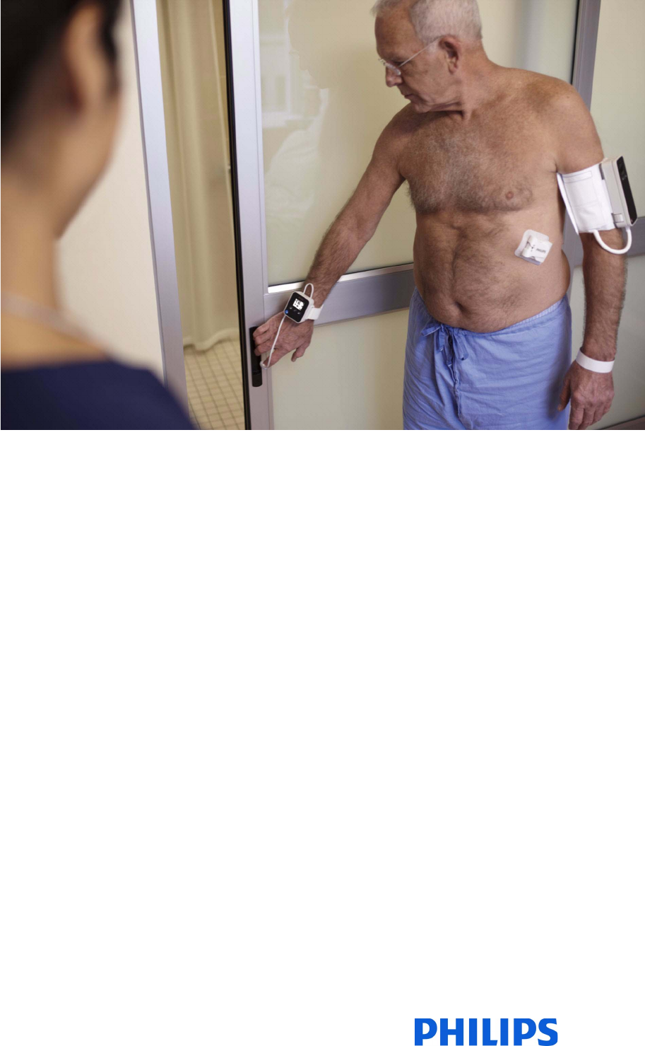
IntelliVue Cableless Measurements refers to the IntelliVue Cableless Measurements product family
consisting of the IntelliVue CL SpO2 Pod (865215), IntelliVue CL NBP Pod (865216) and IntelliVue CL
Respiration Pod (865218) with their accessories. Also included are the auxiliary devices: the IntelliVue CL
Charging Station (865220), IntelliVue CL Transmitter (865221), IntelliVue CL Transmitter Base Station
(865237) and IntelliVue CL Hotspot (865222).
The IntelliVue Cableless Measurements are used for monitoring and recording arterial oxygen saturation,
pulse rate, noninvasive blood pressure and respiration rate of adult and pediatric patients.
Familiarize yourself with all instructions including warnings and cautions, and attend one of the training
courses, before starting to make measurements with patients. Read and keep the Instructions for Use that
come with any accessories, as these contain important information about care and cleaning that is not
repeated here.
When using the IntelliVue Cableless Measurements with an IntelliVue Patient Monitor, an Avalon Fetal
Monitor, a telemetry system or IntelliVue GuardianSoftware, refer to and adhere to all warnings in the
Instructions for Use of the respective device or software.
This guide may contain descriptions of functionality and features that are not implemented in the
equipment currently shipped to Japan and/or of products that are not currently sold in Japan due to
limitations and restrictions under the applicable local laws and regulations in Japan. Please contact your local
sales representative and/or Philips Customer Support for details.
In these Instructions for Use:
•A warning alerts you to a potential serious outcome, adverse event or safety hazard. Failure to observe
a warning may result in death or serious injury to the user or patient.
•A caution alerts you to where special care is necessary for the safe and effective use of the product.
Failure to observe a caution may result in minor or moderate personal injury or damage to the product
or other property, and possibly in a remote risk of more serious injury.
Display refers to the physical display of the Cableless Measurement Device. Screen refers to everything
you see on the IntelliVue Cableless Measurement's display, such as measurement values, patient data and so
forth.
IntelliVue CL Transmitter/WLAN functionality may not be available in all countries.

1 Introduction and Basic Operation
6
Safety Information
Use Environment
WARNING
• If a patient being monitored by Cableless Measurement Devices moves out of range of the patient
monitor, the measurements are not transmitted to the patient monitor or the Information Center. Keep
the patient monitor with the patient during transport.
• Always make sure that the applied pod is assigned to the correct patient.
Electrical Hazards
WARNING
•Electrical shock hazard: Do not open the device housing. Refer all servicing to qualified service
personnel.
• Always use the supplied power cord with the grounded mains plug to connect the charging station to a
grounded AC mains socket. Never adapt the mains plug from the charging station to fit an ungrounded
AC mains socket.
• Do not use AC mains extension cords or multiple portable socket outlets. If a multiple portable socket
outlet without an approved isolation transformer is used, the interruption of its protective grounding
may result in enclosure leakage currents equal to the sum of the individual ground leakage currents, so
exceeding allowable limits.
• Do not connect any devices that are not supported as part of a system.
Radiofrequency Interference
WARNING
• Short Range Radio connections are subject to interruption due to interference from other radio sources
in the vicinity, including microwaves, bluetooth devices, WLAN devices (802.11b,g,n) and cordless
phones. Depending on the strength and duration of the interference, the interruption may occur for an
extended period. A loss of connection, due to moving out-of-range, interference, or for other reasons,
is indicated with a No Host Monitoring INOP on the NBP or SpO2 Pods, or a cl NBP Disconnect, cl
SpO₂ Disconnect or cl Resp Disconnect INOP at the host monitor. Correct channel configuration is
important, refer to the Configuration Guide for details.
Battery Handling
WARNING
• Do not crush or puncture - mechanical abuse can lead to internal damage and internal short circuits
which may not be visible externally.
• Do not incinerate the devices or expose them to temperatures above 60°C (140°F).

1 Introduction and Basic Operation
7
Accessories
WARNING
•Reuse: Never reuse single-patient sensors, accessories and so forth that are intended for single use, or
single patient use only. Reuse may compromise device functionality and system performance and cause
a potential hazard, in particular with regard to cross-contamination.
•Philips’ approval: Use only Philips-approved accessories. Using non-Philips-approved accessories may
compromise device functionality and system performance and cause a potential hazard.
• Using accessories other than those specified may result in increased electromagnetic emission or
decreased electromagnetic immunity of the IntelliVue Cableless Measurement Devices.
Maintenance
WARNING
•Schedule: Failure on the part of the responsible individual hospital or institution employing the use of
this equipment to implement a satisfactory maintenance schedule may cause undue equipment failure
and possible health hazards.
•Contact: If you discover a problem with any of the equipment, contact your service personnel, Philips,
or your authorized supplier.
• If the IntelliVue Cableless Measurement Device is mechanically damaged, or if it is not working
properly, do not use it for any monitoring procedure on a patient, contact your service personnel.
Care, Cleaning and Disposal
WARNING
• If you spill liquid on the equipment, or if the equipment is accidentally immersed in liquid, contact your
service personnel or Philips service engineer. Do not operate the equipment before it has been tested
and approved for further use.
• Do not use flammable agents for disinfecting the equipment in an oxygen-enriched environment, as
this might lead to sudden ignition of vapors, resulting in injury to the patient or staff.
• To avoid contaminating or infecting personnel, the environment or other equipment, make sure you
disinfect and decontaminate the IntelliVue Cableless Measurement Devices appropriately before
disposing of it in accordance with your country's laws for equipment containing electrical and electronic
parts. For disposal of parts and accessories, where not otherwise specified, follow local regulations
regarding disposal of hospital waste.

1 Introduction and Basic Operation
8
Security Information
Protecting Personal Information
Protecting personal health information is a primary component of a security strategy. Each facility using the
devices must provide the protective means necessary to safeguard personal information consistent with
country laws and regulations, and consistent with the facility’s policies for managing this information.
Protection can only be realized if you implement a comprehensive, multi-layered strategy (including policies,
processes, and technologies) to protect information and systems from external and internal threats.
As per their intended use, the devices operate in the patient vicinity and contain personal and sensitive
patient data. They also include controls to allow you to adapt the devices to the patient's care model.
To ensure the patient's safety and protect their personal health information you need a security concept that
includes:
•Physical security access measures - access to the devices must be limited to authorized users. It is
essential that you consider physical security measures to ensure that unauthorized users cannot gain
access.
•Operational security measures - for example, ensuring that devices are powered off after monitoring
in order to remove patient data from the device.
•Procedural security measures - for example, assigning only staff with a specific role the right to use
the devices.
In addition, any security concept must consider the requirements of local country laws and regulations.
Always consider data security aspects of the network topology and configuration when connecting devices
to shared networks. Your medical facility is responsible for the security of the network, where sensitive
patient data from the monitor may be transferred.
When a device is returned for repair, disposed of, or removed from your medical facility for other reasons,
always ensure that all patient data is removed from the device by powering it off.
NOTE
Log files generated by the devices are used for system troubleshooting and do not contain protected health
data.
About HIPAA Rules
If applicable, your facility’s security strategy should include the standards set forth in the Health Insurance
Portability and Accountability Act of 1996 (HIPAA), introduced by the United States Department of Health
and Human Services. You should consider both the security and the privacy rules and the HITECH Act
when designing policies and procedures. For more information, please visit:
http://www.hhs.gov/ocr/privacy/
About the EU Directives
If applicable, your facility’s security strategy should include the practices set forth in the Directive on the
protection of individuals with regard to the processing of personal data and on the free movement of such
data (Directive 95/46/EC of the European Parliament and of the Council of 24 October 1995). In addition,
your facility should also take into account any additional applicable regulation or statutory requirement.
Philips Product Security Policy Statement
Additional security and privacy information can be found on the Philips product security web site at:
http://www.usa.philips.com/healthcare/about/customer-support/product-security

1 Introduction and Basic Operation
9
Manufacturer Disclosure Statement for Medical Device Security – MDS2
You can view the Manufacturer Disclosure Statements for Medical Device Security (MDS2) for specific
devices at:
http://www.usa.philips.com/healthcare/about/customer-support/product-security
1 Introduction and Basic Operation
10
Introducing the IntelliVue Cableless Measurements
The IntelliVue Cableless Measurement Devices provide measurement values and communicate them to
other system components using a wireless short range radio (SRR) interface.
Introduction
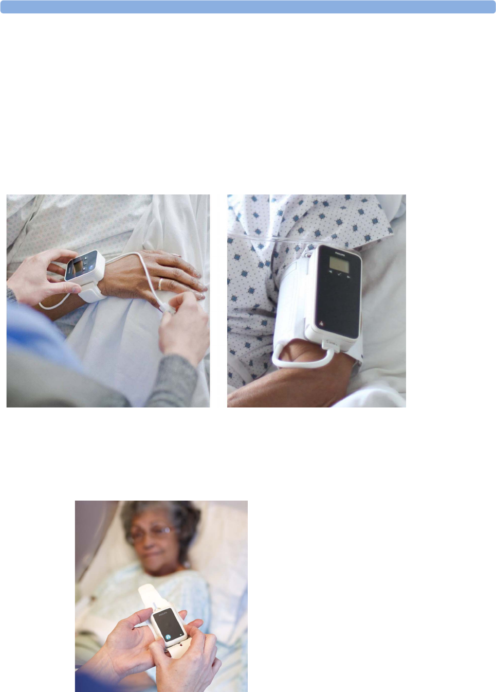
IntelliVue CL SpO2 Pod
The IntelliVue CL SpO2 Pod is a battery powered,
cableless Pulse Oximetry measuring device.
IntelliVue CL NBP Pod
The IntelliVue CL NBP Pod is a battery powered,
cableless, noninvasive blood pressure (NBP)
measuring device.
IntelliVue CL Respiration Pod
The IntelliVue CL Respiration Pod is a battery powered, cableless device for measuring respiration rate
and, optionally, pulse. It also provides basic information about patient posture and activity.
1 Introduction and Basic Operation
11
Basic Operation
IntelliVue CL SpO2 Pod and IntelliVue CL NBP Pod
The IntelliVue CL SpO2 Pod and the IntelliVue CL NBP Pod can be used together with IntelliVue Patient
Monitors MP5/MP5SC/MP5T, MP2/X2, IntelliVue Telemetry System Transceivers TRx4841A/
TRx4851A, MX40 wearable patient monitors, Avalon Fetal Monitors, and IntelliVue GuardianSoftware.
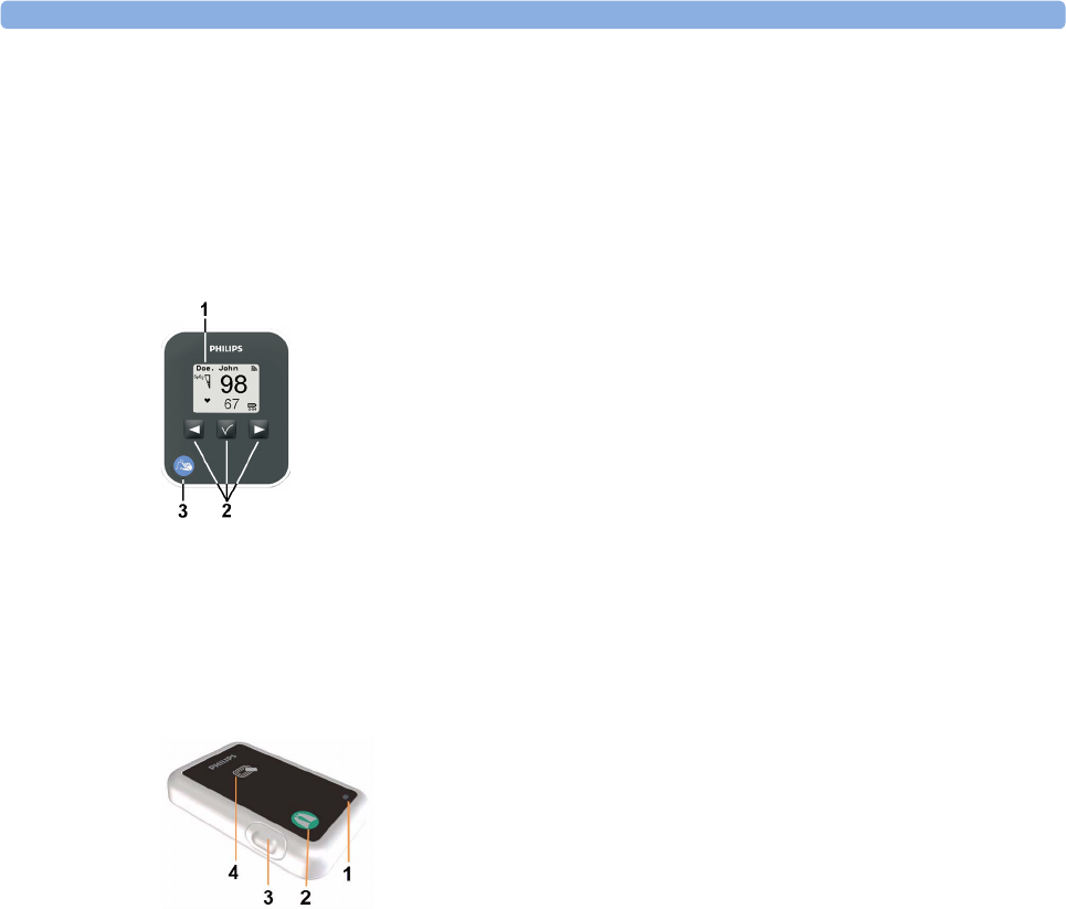
Both devices have an LC display and three keys for basic operation:
IntelliVue CL Respiration Pod
The IntelliVue CL Respiration Pod can be used together with IntelliVue Patient Monitors MP5/MP5SC/
MP5T, MP2/X2, or IntelliVue GuardianSoftware. The device has one multi-color LED for status display
and one hardkey for basic operation, e.g. to start a measurement.
1Integrated monochrome LC display
2Hardkeys
3Measurement identifier
1Multi-color LED
2Measurement identifier
3Hardkey
4Indication for built-in RFID tag

1 Introduction and Basic Operation
12
2
13
2IntelliVue CL SpO2 Pod
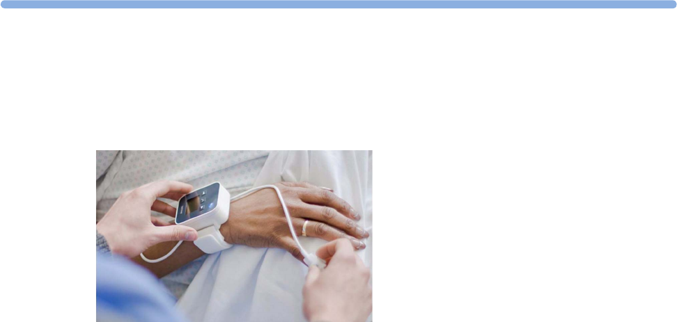
The IntelliVue CL SpO2 Pod is a wrist-worn device; you need a Mobile CL SpO2 Cradle to hold the sensor
connector in place and a wristband to fix the cradle to a patient's arm.
Specialized single-patient SpO2 sensors are available for use with the IntelliVue CL SpO2 Pod. For details
regarding the complete set of single-patient supplies, cradle, wristband and sensors, refer to “IntelliVue CL
SpO2 Pod Accessories” on page 52.
General Operation of the SpO2 Pod
The following sections describe operation on the SpO2 Pod itself. For operation from a patient monitor, see
“Controls Available with a Patient Monitor” on page 25. For operation from an Information Center via a
telemetry system, see “Controls Available with a Telemetry Device” on page 26. For operation with
IntelliVue GuardianSoftware, see “Controls Available with GuardianSoftware” on page 27.
The SpO2 Pod has three hardkeys for basic operation and a set of configurable SmartKeys which appear on
the screen. These are used to activate and navigate through the on-screen menus and to select individual
items. The typical operator's position is such that everything on the device's display can be read clearly and
easily.
Switching the Device On
The first time an SpO2 Pod is used, or after the device has been powered off for storage, place it on the
IntelliVue CL Charging Station. This will automatically switch the device on.
If the SpO2 Pod has only been switched off temporarily (see “Switching the Device Off” on page 17), press
any hardkey to turn the device on again.
When an SpO2 Pod is not operated, it will automatically switch off the screen lighting after a short time. A
little later the low-activity screen will be displayed.
2 IntelliVue CL SpO2 Pod
14
Screen Layout
There are three variations of the Main Screen layout depending on the Alarm status and the general activity
level.
Standard Layout
Alarm Layout
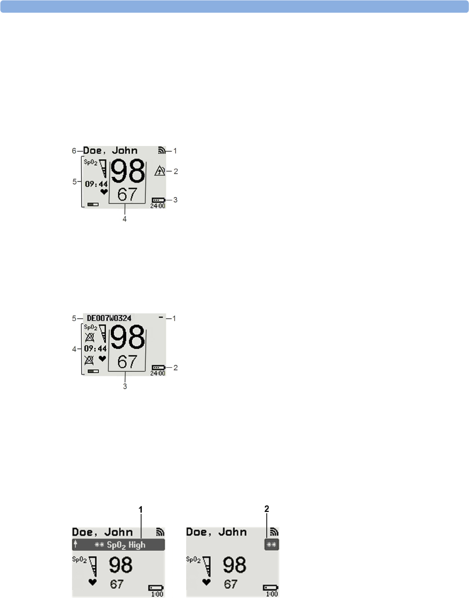
If an alarm occurs the full alarm message appears at the top of the screen. After the alarm message has been
silenced the alarm indicator is shown as a symbol on the right side of the screen.
When assigned to a monitor, telemetry device or a patient in GuardianSoftware:
1Connection status indicator
2Indicator that alarming capability has been transferred to
the host (to the monitor or, for the telemetry device, to
the Information Center). No patient alarms will be
announced on the Cableless Measurement Device.
3Battery indicator
4Measurement values
5Measurement-related symbols (see the “Monitoring
SpO2” section for details)
6Patient identification
When not assigned to a monitor or telemetry device:
1Connection status indicator
2Battery indicator
3Measurement values
4Measurement-related symbols (see the “Monitoring
SpO2” section for details). The Alarms Off symbols
indicate that no physiological alarms are available from
the Cableless Measurement Devices when not assigned
to a host.
5Cableless Measurement Device equipment label
1Full length alarm message
2Alarm indicator

2 IntelliVue CL SpO2 Pod
15
Low-Activity Screen
If the Cableless Measurement Device has not been operated for a while, the screen lighting will switch itself
off and a little later the screen will switch to a pre-configured "low-activity" screen.
When a Cableless Measurement Device Cannot be Activated
If you cannot activate a device by pressing a key, place it on the IntelliVue CL Charging Station. The device
becomes active. Check the battery status. If necessary, leave the device on the charger until the battery is
fully charged.
Using the Hardkeys
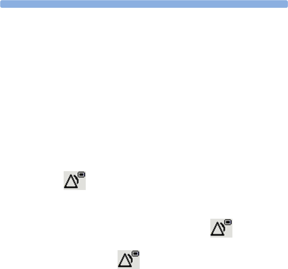
The IntelliVue Cableless Measurement Devices have three hardkeys: ◄, , ►.
Use ◄ and ► to navigate through SmartKeys and menus and to select items or to silence alarms.
The three hardkeys also have an additional function when the key is held down for a couple of seconds:
Using the SmartKeys
A SmartKey is a graphical key which appears on the screen and gives you fast access to functions.
SmartKeys Menu
Press the hardkey (without any screen element highlighted) to get to the SmartKeys menu.
Use the ◄ and ► hardkeys to move along the row of SmartKeys. The highlighted SmartKey is displayed in
full above the row of SmartKeys. When you use the ◄ or ► hardkey at the end of the row, an Exit screen
appears and then with further presses you move on to the next page of SmartKeys. To leave the SmartKeys
menu you can use the Exit screen or press the ► hardkey for a couple of seconds to return to the Main
Screen.
When the required SmartKey is highlighted, press the key to activate the corresponding function.
To get to the next page of the SmartKeys menu, highlight the rightmost SmartKey then press the ► key.
◄opens the Add To screen to assign a device (or to unassign it when it is already assigned)
opens the SmartKeys menu
►returns to the Main Screen. If already on the Main Screen, it locks the keys and a lock symbol
appears on the screen above the battery symbol. If keys are already locked, it unlocks the keys and
the lock symbol disappears
2 IntelliVue CL SpO2 Pod
16
List of Available SmartKeys
SmartKey Text Labels
Main Setup
start an SpO2 measurement
set the SpO2 mode
Add/Remove device
enter Battery menu
enter Profiles menu
change Screen
put device in standby mode (or power off when pressed for more than two
seconds)
enter Patient menu
enters the Alarms menu to access: Alarm Messages, Alarm Limits, Alarms On/
Off/Pause, Alarm Volume.
Change alarm volume
Change pulse tone volume

2 IntelliVue CL SpO2 Pod
17
Using the Main Setup Menu
In addition to the hardkeys and SmartKeys for the most needed functions, the Main Setup menu gets you to
all settings that can be adjusted for the respective device. Select the Main Setup SmartKey to get to the Main
Setup menu.
Switching the Device Off
To put the device in standby mode, select the Standby SmartKey, then Confirm.
If you keep Standby pressed for more than two seconds, you can choose between Standby or Power Off.
•Standby means that the display is switched off and the measurements are disabled. Use this option if
your device is not used temporarily. Press any hardkey to turn the device on again.
•Power Off means that the device is switched off completely and can only be switched on again by
putting it on a charger. Use this option when the device is not used for a longer time or prepared for
storage or shipping.
Auto Standby and Auto Power Off
The device can be configured to automatically go into standby mode after a configurable time span of
inactivity. When in standby mode, the device can be automatically powered off after a configurable time
span. See the IntelliVue Cableless Measurements Configuration Guide for details on how to configure these
settings.
Operating Modes
Your device has four operating modes. Some are passcode protected.
•Monitoring Mode: This is the normal, every day working mode that you use for making
measurements. You can change elements such as measurement modes, patient category and so forth.
When you remove the patient from the device, these elements return to their default values. Changes
can be stored permanently only in Configuration Mode. You may see items, such as some menu
options, that are visible but 'grayed out' so that you can neither select nor change them. These are
present for your information only and can be changed only in Configuration Mode.
•Demonstration Mode: Passcode protected, this is for demonstration purposes only. You must not
change into Demonstration Mode during monitoring.
•Configuration Mode: Passcode protected, this mode is for personnel trained in configuration tasks.
These tasks are described in the Configuration Guide. During installation the Cableless Measurement
Device is configured for use in your environment. This configuration defines the default settings you
work with when you switch on.
Main Setup
SpO₂
Pulse
Alarms
Patient
Equipment
User Interface
Standby
Profiles
Operating Modes
Date, Time
Battery
Revisions

2 IntelliVue CL SpO2 Pod
18
•Service Mode: Passcode protected, this is for trained service personnel.
When you switch the device on, it starts up in monitoring mode. To change to a different mode:
1Use the Main Setup SmartKey to get to the Main Setup menu.
2Select Operating Modes and choose the mode you require.
Using the Patient Menu
The Patient menu allows you to see patient demographics information and to remove a patient from a
device. Patient Demographic information is only displayed if the Cableless Measurement Device is assigned
to a patient monitor or GuardianSoftware. Patient Category is the only item of patient data which can be
changed at the Cableless Measurement Device, but only when the device is not assigned to a patient
monitor or telemetry device.
Displaying the Patient Menu
To display the Patient menu,
• select the Patient SmartKey, or
• select the Main Setup SmartKey followed by Patient.
Stop Using a Device for a Patient
To remove a patient from the Cableless Measurement Device,
•in the Patient menu select Free Device.
All patient data is cleared, settings are reset to the defaults and the device is removed from the monitor or
telemetry device.
NOTE
Depending on your configuration, when the device is put on the charger, patient data will also be cleared
and the device will be free for another patient.
Using the Device for a New Patient
To use a device for a new patient,
•in the Patient menu, select New Patient.
If the device was not free, the existing data will be deleted and the profile set to the default.
Using Profiles
A profile is a set of measurement and general settings which have been customized for a particular purpose.
The Cableless Measurement Devices can have four different profiles configured to your requirements. The
default profile is marked with a symbol.
To select a different profile,
1Select the Profiles SmartKey or the Main Setup SmartKey followed by Profiles.
2Select the required profile from the list.
Selecting New Patient or Free Device will always reset the profile to the default.

2 IntelliVue CL SpO2 Pod
19
Setting the Date and Time
If the Cableless Measurement Device is assigned to a patient monitor, telemetry device or
GuardianSoftware, the date and time will be taken from the host. If this is not the case, you can set the date
and time on the Cableless Measurement Device,
1Select the Main Setup SmartKey and then Date, Time.
2Enter the data for date and time one after another.
3Select Store Date, Time.
If the time has not been set, --:-- will display on the device.
Battery Status
The IntelliVue CL SpO2 Pods show their battery status on their display both in operating and charging
condition. The battery status indicator is located in the lower right corner of the screen during operation
and in the middle of the screen during charging.
Battery Status Menu
Select the Battery SmartKey or Main Setup followed by Battery using the ◄ and ► keys, then press the
key to open the Battery menu. The Battery menu provides the following information: full-charge and
remaining capacity, voltage, current and temperature.

2 IntelliVue CL SpO2 Pod
20
Connection with Host Systems
The following sections describe how the IntelliVue Cableless Measurement Devices work together with
host systems (Patient Monitors, Fetal Monitors, Telemetry Devices / Information Center or
GuardianSoftware).
IntelliVue Cableless Measurements Use Models
With these patient-worn measurement devices you can measure and transmit a patient's vitals regularly or
on an intermittent data collection basis. There are four typical use models:
With a Patient Monitor
The IntelliVue Cableless Measurement Devices can be used together with an MP5/MP5SC/MP5T, MP2 or
X2 patient monitor (with an SRR interface). They can communicate their measurement values via short
range radio to the monitor. The monitor may be assigned to a patient sector at the IntelliVue Information
Center (IIC). When assigned to the Information Center, certain actions can be performed at both the
patient monitor and the Information Center. See the table “Controls Available with a Patient Monitor” on
page 25.
In situations where patients are becoming more mobile (for example, in step-down/intermediate care units)
the lightweight Cableless Measurement Devices allow increased mobility within the short range radio range,
without giving up vital signs monitoring.
When assigned to a patient monitor, the Cableless Measurement Device can be selected for use in patient
transport at the patient monitor (for details see the Patient Monitor Instructions for Use). In this case, the
Cableless Measurement Device will perform local attended monitoring. The patient must be attended by
a caregiver during transport, to ensure that alarms on the Cableless Measurement Device are recognized. In
local attended monitoring mode, an alarm message text appears in the alarm status area at the top of the
screen indicating the source of the alarm and an alarm tone is issued. See “Alarms” on page 34 for details.
A telemetry device can be assigned to a patient monitor equipped with short range radio at the same time as
any Cableless Measurement Devices are also assigned to this monitor.
When assigned to a patient monitor, the admitted patient name is displayed on the SpO2 Pod.
If the connection between the monitor and the Cableless Measurement Device is lost, an INOP will be
displayed at the monitor: cl SpO₂ Disconnect. A No Host Monitoring INOP will be displayed on the SpO2
Pod, and an INOP tone will sound. In this case, visual and audible alarms are still available at the SpO2 Pod,
but it is not possible to change the alarm settings.
With a Fetal Monitor
In combination with an Avalon CL Transducer System, the IntelliVue CL SpO2 Pod can be used together
with an Avalon FM 20-50 Fetal Monitor. The SpO2 Pods are assigned to the fetal monitor by docking them
at the Avalon CL Base Station. For information about Avalon Fetal Monitors, the Avalon CL Transducer
System and the Avalon CL Base Station, please refer to the Avalon Fetal Monitor Instructions for Use.
With a Telemetry Device
The Cableless Measurement Devices can be assigned to a patient with the telemetry device TRx4841A/
TRx4851A or an MX40 wearable patient monitor. They can communicate their measurement values via
short range radio to the telemetry device which communicates them to an IntelliVue Information Center to
provide a consolidated set of patient values.
Some of the measurement tasks can be performed remotely from the Information Center. See the table
“Controls Available with a Telemetry Device” on page 26.
If the patient name is available at the Information Center, it will be also displayed on the SpO2 Pod.

2 IntelliVue CL SpO2 Pod
21
When a Cableless Measurement Device is assigned to a telemetry device, it is not possible for the telemetry
device to be wirelessly assigned or directly connected to a patient monitor.
If the connection between the telemetry device and the Cableless Measurement Device is lost, an INOP will
be displayed at the Information Center: cl SpO₂ Disconnect. A No System Monitor. INOP will be displayed
on the SpO2 Pod, and an INOP tone will sound.
With IntelliVue GuardianSoftware
The Cableless Measurement Devices can be used together with IntelliVue GuardianSoftware.
GuardianSoftware collects non-continuous vital signs data that are transmitted via a Transmitter, Hotspot
or MP5 from the Cableless Measurement Devices. Using the collected data, it provides trending, review,
reporting and notification. The Guardian Early Warning Scoring (Guardian EWS) application provides
basic assessment guidance, helping you to recognize the early signs of deterioration in your patients.
GuardianSoftware is not intended for monitoring in combination with Cableless Measurement Devices.
Some of the measurement tasks can be performed remotely from GuardianSoftware. See the table
“Controls Available with GuardianSoftware” on page 27. GuardianSoftware also manages the patient data.
If the connection between GuardianSoftware and the Cableless Measurement Device is lost, the connection
symbol will be displayed gray at GuardianSoftware. A No System INOP will be displayed on the SpO2 Pod
(no alarm sound).
If a patient name is available at GuardianSoftware, it will be also displayed on the Pod. Any update of
patient data will be synchronized between the Pods and GuardianSoftware. The only patient management
action available directly at the Pod is Free Device. Selecting Free Device removes the current patient from
the Pod and resets the Pod to the default profile. The Pod is unassigned.
Device Compatibility
The IntelliVue CL SpO2 Pods require the following software levels in the associated equipment:
• IntelliVue Patient Monitor - Release H.0 or above
• Avalon Fetal Monitor in combination with an Avalon CL Transducer System - Release J.3 or above
• IntelliVue Information Center - Release M or above
• Philips Patient Information Center iX - Release A or above
• Telemetry device TRx4841A/TRx4851A - Revision D.00.22 or above
• MX40 wearable patient monitor - Revision A.0 or above
• IntelliVue GuardianSoftware - Revision A.0 or above
Availability of Patient Alarms
When the IntelliVue CL SpO2 Pod is used alone, without an assignment to a monitor or telemetry device,
no patient alarms will be generated.
When the IntelliVue CL SpO2 Pod is assigned to a patient monitor or telemetry device and a short range
radio connection exists, alarms may be announced at the patient monitor or the Information Center.
•When assigned to a patient monitor / fetal monitor: Alarm messages will be displayed and audible
alarm indicators sounded at the monitor in the same way and under the same conditions as for its own
measurements. See the Instructions for Use of the patient monitor for details.
If a Cableless Measurement Device that is assigned to a patient monitor is selected for use in patient
transport at the patient monitor, the Cableless Measurement Device will perform local attended
monitoring. See the Instructions for Use of the patient monitor for details on how to do this. The
patient must be attended by a caregiver during transport, to ensure that alarms on the Cableless
Measurement Device are recognized. In local attended monitoring mode, an alarm message text

2 IntelliVue CL SpO2 Pod
22
appears in the alarm status area at the top of the screen indicating the source of the alarm and an alarm
tone is issued. See “Alarms” on page 34 for details.
•When assigned to a telemetry device: Measurement values sent via the telemetry device to the
IntelliVue Information Center can generate alarms at the Information Center when the values meet the
criteria set there for alarms. The alarms will be announced in the same way as measurements from other
sources. See the Instructions for Use of the Information Center for details.
•When assigned to GuardianSoftware: Measurement values sent via transmitter, hotspot or MP5 to
IntelliVue GuardianSoftware will be visualized in GuardianSoftware. Since IntelliVue GuardianSoftware
is a data management system, no alarms are announced. The IntelliVue Cableless Measurement Devices
will also not generate physiological alarms when connected to IntelliVue GuardianSoftware. See the
Instructions for Use of GuardianSoftware.
Assigning an IntelliVue Cableless Measurement Device to a Host
When an IntelliVue CL SpO2 Pod is used with a host system (patient monitor, telemetry device or
GuardianSoftware), the Pod must be assigned to that host system.
The assignment can be done at the CL SpO2 Pod itself or at the host system (patient monitor or
GuardianSoftware).
WARNING
Always make sure that the applied CL SpO2 Pod is assigned to the correct patient.
WARNING
Short Range Radio connections are subject to interruption due to interference from other radio sources in
the vicinity, including microwaves, bluetooth devices, WLAN devices (802.11b,g,n) and cordless phones.
Depending on the strength and duration of the interference, the interruption may occur for an extended
period. A loss of connection, due to moving out-of-range, interference, or for other reasons, is indicated
with a No Host Monitoring INOP on the SpO2 Pod, or a cl SpO₂ Disconnect INOP at the host monitor.
Correct channel configuration is important, refer to the Configuration Guide for details.
Assignment at the Measurement Device
To make an assignment, select:
•the
Add/Remove SmartKey , or
• hold the ◄key pressed.
This opens the Add To menu which lists the available patient monitors and telemetry devices within the SRR
range. In order to save power, the list is only visible for a short time; the menu is automatically closed after
40 seconds.
Telemetry device: A telemetry device must be put into assignment mode by pressing the key on the
telemetry device before it can appear in the list. Pressing the key starts an SRR channel search to find
the clearest channel available. During the search all 4 LEDs will blink once per second. The search will

2 IntelliVue CL SpO2 Pod
23
take approximately 20-25 seconds. Once a channel is identified, the first LED will light up and blink
once per second to indicate that the telemetry device is ready for assignment.
1Select a patient monitor or telemetry system using the ◄ and ► keys.
If you select a patient monitor, the measurement selection key on that monitor will change to show the
type of measurement device.
2Activate the assignment by pressing the key twice on the measurement device.
The Cableless Measurement Device is assigned to the selected patient monitor or telemetry device. A
telemetry device plays the assignment tone when the assignment is successful. A patient monitor issues
an assignment prompt message.
If the internal measurement in the patient monitor is active (the measurement selection key has a yellow
frame), you will need to confirm that it should be deactivated in favor of the Cableless Measurement Device
you want to assign. To do this:
1Select the measurement selection key on the monitor.
A prompt message appears with the Confirm and Cancel keys.
2Select Confirm to deactivate the internal measurement.
When the Cableless Measurement Device is assigned, the symbol appears on its display indicating that
alarming capability has been transferred to the host (to the monitor or, for the telemetry device, to the
Information Center). No patient alarms will be announced on the Cableless Measurement Device.
To unassign the measurement device from the monitor or telemetry system, select the Add/Remove
SmartKey, then select Remove From. After confirmation the SRR connection is disconnected.
Assignment at the Patient Monitor
Assignment at the Patient Monitor
Prepare the Cableless Measurement Device for assignment by activating the Add/Remove SmartKey.
At the patient monitor,
1Select the Measurement Selection key.
2Select the Add cl Msmt pop-up key.
This opens the Add cl Measurement window, which shows the available Cableless Measurement
Devices:
3Select the device which you want to assign to the patient in the monitor.
4The monitor displays the assignment prompt message.
If the internal measurement in the patient monitor is active, you will need to confirm that it should be
deactivated in favor of the Cableless Measurement Device you want to assign.
When the Cableless Measurement Device is assigned, the symbol appears on its display indicating that
alarms from the device will be sent to the patient monitor.
Add To
Mon 1
Mon 2
Tele 33
Tele 44
2 IntelliVue CL SpO2 Pod
24
An assigned Cableless Measurement Device can be removed in the Measurement Selection window. For
more details see the Instructions for Use for your patient monitor.
Assignment with an RFID Reader and Tagged Cableless Devices
You can directly assign all cableless devices that have RFID tags with a Philips HS1-R RFID/barcode
reader. The SpO2 Pod used must have an IntelliVue ProxiTag RFID tag adhesively attached.
1Hold the cableless device close to the reader.
Depending on its configuration, the reader beeps, vibrates or indicates via the LEDs when it has read
the tag.
2Press any hardkey on the cableless device.
The Cableless Measurement Device is now added to the monitor.
If the corresponding internal measurement in the patient monitor is active, you will be asked to confirm that
it should be deactivated in favor of the Cableless Measurement Device by selecting Replace.
If a Cableless Measurement of the same type is already assigned to the monitor, you will be asked to confirm
that it should be removed by selecting Replace.
Assignment at the Fetal Monitor
The first time an IntelliVue Cableless Measurement Device is used with an Avalon Fetal Monitor, or after a
device has been powered off for storage, place it on the Avalon CL Base Station. This will automatically
switch the device on. The device is assigned automatically to the Fetal Monitor working with the CL Base
Station.
NOTE
When you place a Cableless Measurement Device onto an Avalon CL Base Station to assign it to an Avalon
Fetal Monitor, the Cableless Measurement Device is automatically unassigned from the previous patient.
Special Conditions when Working with Fetal Monitors
The following special conditions apply when CL SpO2 Pods are operating with an Avalon Fetal Monitor as
a host:
•The SpO
2 Pods are intended to measure the maternal SpO2 and Pulse. The patient category is always
Adult.
•The
Pulse measurement is always On. The Pulse: On/Off setting is not available.
• Physiological alarms are only available at the Avalon Fetal Monitor, not at the Cableless Measurement
Devices. Local attended monitoring is not available: Use for Transp. is not supported. (Local attended
monitoring is used for displaying alarms locally at the Cableless Measurement Devices during patient
transport, when the patient is attended by a caregiver).
• Alarm-related operations (e.g. switching alarms on and off, setting the high and low alarm limits) are
not available when Alarm Mode is set to INOP only in the Avalon Fetal Monitor. See the Avalon Fetal
Monitor Instructions for Use and Avalon Fetal Monitor Configuration Guide for further information.

2 IntelliVue CL SpO2 Pod
25
• You can use the Remove operation at the host to remove Cableless Measurement Devices, as described
in the Avalon Fetal Monitor Instructions for Use.
• Averaging Time is not configurable.
• Smart Alarm Delay is not supported.
• Pulse tone from the CL SpO2 Pod is not supported at the Avalon Fetal Monitor.
•Perfusion is always Off and cannot be changed to On.
• Perfusion Change Indicator is not supported.
• It is not possible to change the label, it is always SpO₂.
• Continuous mode only. The functions for starting a measurement, selecting the measurement mode
and setting the repetition time are not supported.
• Configuration of Aging Time (for Aging Numerics) is not possible.
• Pleth wave is not available.
Assignment with GuardianSoftware
To assign a Cableless Measurement Device to a patient in GuardianSoftware:
1Select the patient on the Chalkboard.
2Take the Cableless Measurement Device from the charger.
3On the Equipment List tab, select the Cableless Measurement Device on the Available Equipment list,
highlighted in green on top of the list. The device on top of the list is always the one with the most
recent user interaction (taken off the charger, put on the charger, or key pressed).
4Click Use for Patient to assign the device to the patient.
Controls Available with a Patient Monitor
The controls available when working with the Cableless Measurement Device and a patient monitor are
described in the table below.
* except when SRR connection to host is lost
Action At the Cableless
Measurement
Device
At the Patient
Monitor
At the IIC
Start SpO2Yes Yes No
Change SpO2 Mode Yes Yes No
Select SpO2 Repetition Time Yes Yes No
Assign SpO2 Pod Yes Yes No
Remove SpO2 Pod Yes Yes No
Change Alarm Limits Yes* Yes No
Place Device in Standby Yes Yes Yes
Alarm Silence Yes Yes Yes
Alarm Off/Pause Yes Yes Yes

2 IntelliVue CL SpO2 Pod
26
WARNING
If a patient being monitored by Cableless Measurement Devices moves out of range of the patient monitor,
the measurements are not transmitted to the patient monitor or the Information Center. The measurements
are available on the Cableless Measurement Device only. If this occurs, the No Host Monitoring message is
displayed on the measurement device. The measurement device will also sound the INOP tone.
Controls Available with a Telemetry Device
The controls available when working with the Cableless Measurement Device and a TRx4841/TRx4851A
Transceiver or MX40 wearable patient monitor with a short range radio adapter (SRRA) are described in the
table below.
NOTE
When you unplug the ECG cable from the telemetry device and plug it into the monitor associated with the
same patient, the ECG source will automatically be from the monitor. The SpO2 measurement devices
assigned to the telemetry device will continue to source data to the telemetry device and the Information
Center. You may need to change screens on the patient monitor to see the measurements.
NOTE
The SpO2 measurement sourced from the telemetry device (label: SpO2T) has priority over the
IntelliVue CL SpO2 measurement. The SpO2T measurement is sent to the Information Center as long as it
is available and the IntelliVue CL SpO2 measurement is available on the measurement device only.
Action At the Cableless
Measurement Device
At the IIC
Start SpO2Yes Yes
Change SpO2 Mode Yes Yes
Select SpO2 Repetition Time Yes No
Assign SpO2 Pod Yes No
Remove SpO2 Pod Yes Yes
Change Alarm Limits No Yes
Place Device in Standby No No
Alarm Silence No Yes
Alarm Off/Pause No Yes

2 IntelliVue CL SpO2 Pod
27
Controls Available with GuardianSoftware
The controls available when working with the Cableless Measurement Device and GuardianSoftware are
described in the table below.
Trending
The IntelliVue Cableless Measurement Devices provide data for trending of parameters. The trended data
are only available via a host system. For details on trends see the Instructions for Use of your host system.
When the connection to the host is lost during measurement, the IntelliVue Cableless Measurement
Devices are able to collect data in a local memory. These data can be uploaded to GuardianSoftware, but
not to other host systems, when a connection is established at a later stage.
Action At the Cableless
Measurement Device
At GuardianSoftware
Start SpO2Yes Yes
Change Mode Yes Yes
Select SpO2 Repetition Time Yes Yes
Assign SpO2 Pod Yes Yes
Remove SpO2 Pod Yes Yes
Place Device in Standby No No
Technical Alarm Silence No Yes
Alarm Off/Pause No No

2 IntelliVue CL SpO2 Pod
28
Monitoring SpO2
Philips pulse oximetry uses a motion-tolerant signal processing algorithm, based on Fourier artifact
suppression technology (FAST). A sensor is used that transmits light of two different wavelengths through
the tissue of the patient. The measurement principle of pulse oximetry is based on the specific absorption
characteristics of oxyhemoglobin and deoxyhemoglobin and the pulsating arteriolar vascular bed at the
measurement site. It provides four measurements:
• Oxygen saturation of arterial blood (SpO2) - percentage of oxygenated hemoglobin in relation to the
sum of oxyhemoglobin and deoxyhemoglobin (functional arterial oxygen saturation).
• Pleth waveform - auto-scaled visual indication of patient's pulse which is not directly proportional to
the pulse volume (only on patient monitor, GuardianSoftware or Information Center, if assigned).
• Pulse rate (derived from pleth wave) - detected pulsations per minute.
• Perfusion indicator - numerical value for the pulsatile portion of the measured signal caused by arterial
pulsation (only on patient monitor, if assigned).
NOTE
No alarms are generated for SpO2 and Pulse when measuring SpO2 with the SpO2 Pod not assigned to a
patient monitor or telemetry device.
The SpO2 measurement is suitable for use in the presence of electrosurgery and during the discharge of a
cardiac defibrillator according to IEC 80601-2-30.
SpO2 Sensors
Specialized SpO2 Sensors are available for use with the IntelliVue CL SpO2 Pod. See the “IntelliVue CL
SpO2 Pod Accessories” section for details.
Familiarize yourself with the Instructions for Use supplied with your sensor before using it. In particular,
check that the sensor being used is appropriate for your patient category and application site.
Additional Information
The following documents contain additional information, depending on which accessories you are using:
• Mobile CL Single-Patient SpO2 Sensor Instructions for Use
• Mobile CL Reusable SpO2 Sensor1 Instructions for Use
• Mobile CL SpO2 Wristband Instructions for Use
1 may not be available in all geographies
2 IntelliVue CL SpO2 Pod
29
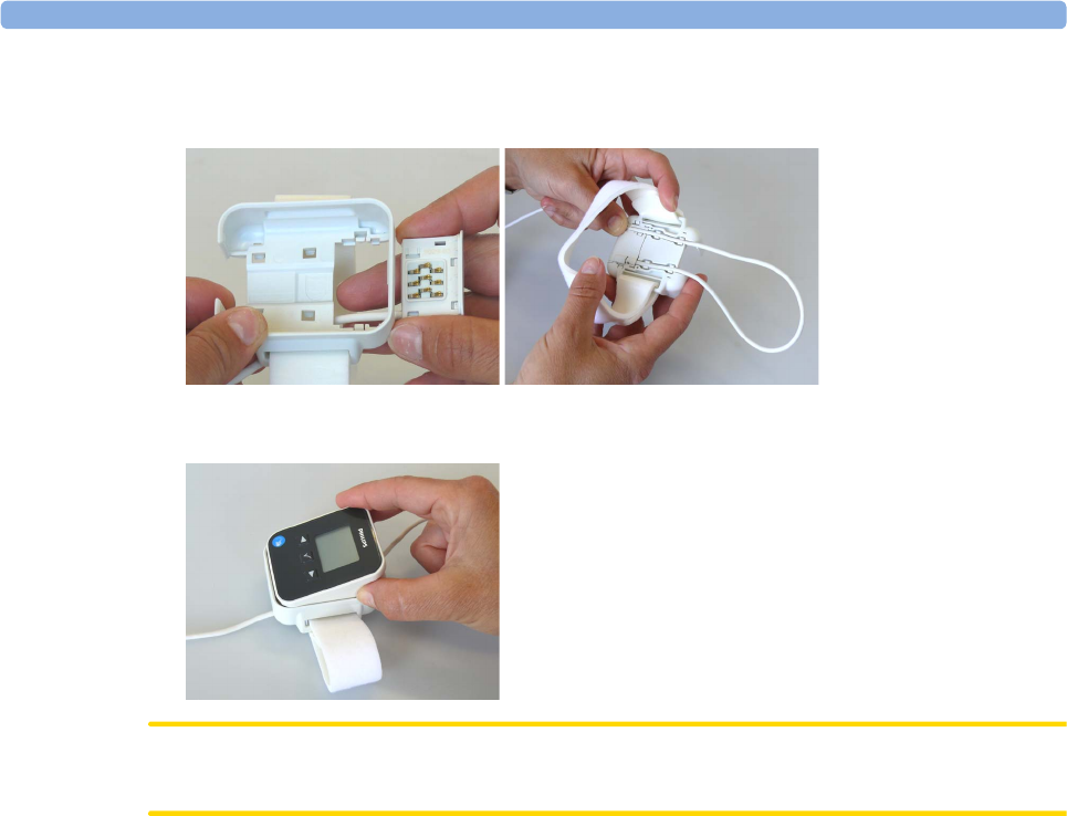
Connecting SpO2 Sensors
1Connect the sensor to the single patient Mobile CL SpO2 Cradle (if not already connected).
2Insert the SpO2 Pod into the Mobile CL SpO2 Cradle. The correct orientation is indicated by a
matching blue dot inside the cradle.
CAUTION
Make sure that the contacts of the SpO2 Pod and the sensor are dry and free of residues.
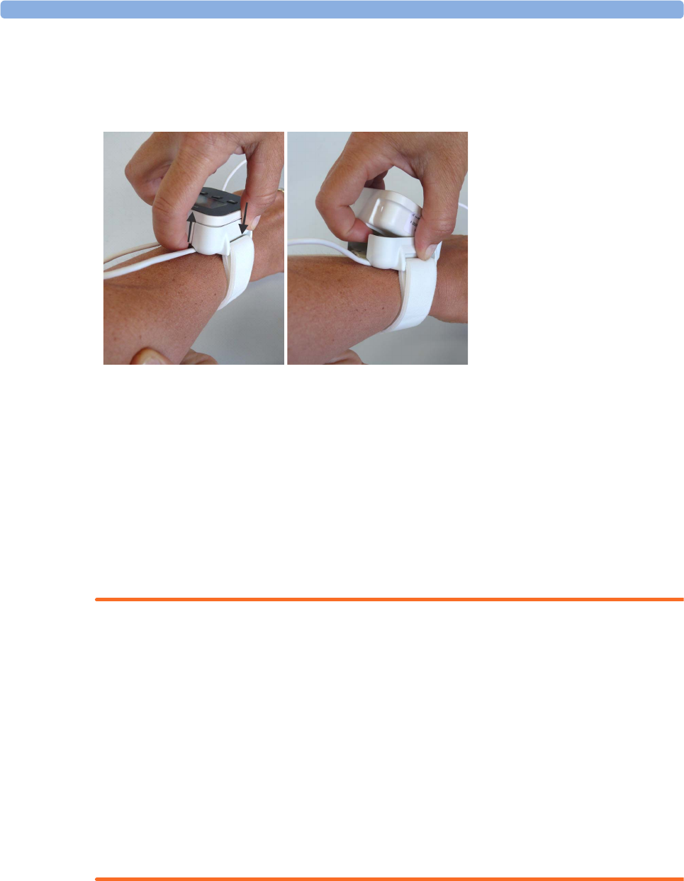
3Secure the cradle on the patient's arm using the wristband.
a. Feed the free end of the wristband through the slot in the cradle, starting from the underside of the
cradle.
b. Slide the wristband onto the patient's arm and pull the free end until the wristband fits snugly.
c. Close the wristband using the Velcro patch on the free end of the band.
2 IntelliVue CL SpO2 Pod
30
Removing the Pod from the Cradle
To remove the SpO2 Pod from the cradle, pull on the Pod at the opening in the cradle, while holding the
cradle in place on the patient's arm.
Applying the Sensor
1Choose a finger of the patient that matches the sensor dimension in a way that the sensor optical
components are properly aligned and the sensor is neither too loose nor applies too much pressure to
the finger. For small pediatric patients consider the thumb.
2Remove colored nail polish from the application site.
3Apply the sensor to the patient. The application site should match the sensor size so that the sensor can
neither fall off, nor apply excessive pressure. See the sections below for details on applying the different
sensors.
4Check that the light emitter and the photodetector are directly opposite each other. All light from the
emitter must pass through the patient's tissue.
WARNING
Proper Sensor Fit: If a sensor is too loose, it might compromise the optical alignment or fall off. If it is too
tight, for example because the application site is too large or becomes too large due to edema, excessive
pressure may be applied. This can result in venous congestion distal from the application site, leading to
interstitial edema, hypoxemia and tissue malnutrition. Skin irritations or lacerations may occur as a result of
the sensor being attached to one location for too long. To avoid skin irritations and lacerations, periodically
inspect the sensor application site and change the application site regularly.
Venous Pulsation: Do not apply sensor too tightly as this results in venous pulsation which may severely
obstruct circulation and lead to inaccurate measurements.
Ambient Temperature: At elevated ambient temperatures be careful with measurement sites that are not
well perfused, because this can cause severe burns after prolonged application. All listed sensors operate
without risk of exceeding 41°C on the skin if the initial skin temperature does not exceed 35°C.
Extremities to Avoid: Avoid placing the sensor on extremities with an arterial catheter, an NBP cuff or an
intravascular venous infusion line.

2 IntelliVue CL SpO2 Pod
31
Measuring SpO2
During measurement, ensure that the application site:
– has a pulsatile flow, ideally with a perfusion indicator value above 1.0 or, if the perfusion indicator is
not available, with signal quality indicator of at least medium.
– has not changed in its thickness (for example, due to edema), causing an improper fit of the sensor.
WARNING
• If not specified otherwise in the SpO2 sensor's instructions for use, the following applies:
– For fully conscious pediatric or adult patients, who have a normal function of perfusion and
sensory perception at the measurement site:
To ensure skin quality and correct optical alignment of the sensor, inspect the application site when
the measurement results are suspicious or when the patient complains about pressure at the
application site, but at least every 24 hours. Correct the sensor alignment if necessary. Move the
sensor to another site, if the skin quality changes.
– For all other patients:
Inspect the application site every two to three hours to ensure skin quality and correct optical
alignment. Correct the sensor alignment if necessary. If the skin quality changes, move the sensor
to another site.
Change the application site at least every four hours.
• Injected dyes such as methylene blue, or intravascular dyshemoglobins such as methemoglobin and
carboxyhemoglobin may lead to inaccurate measurements.
• Inaccurate measurements may result when the application site for the sensor is deeply pigmented or
deeply colored, for example, with nail polish, artificial nails, dye or pigmented cream.
• Interference can be caused by:
– High levels of ambient light (including IR warmers) or strobe lights or flashing lights (such as fire
alarm lamps). (Hint: cover application site with opaque material.)
– Another SpO2 sensor in close proximity (e.g. when more than one SpO2 measurement is
performed on the same patient). Always cover both sensors with opaque material to reduce cross-
interference.
– Electromagnetic interference, especially at perfusion indicator values below 1.0 or signal quality
indicator below medium.
– Excessive patient movement and vibration.
Selecting Measurement Modes
There are three different modes available for making SpO2 measurements:
•Continuous mode - SpO2 is measured continuously until the measurement is switched off.
•Manual mode - a single SpO2 measurement is made when the Start SpO₂ SmartKey or the Start SpO₂
menu item is selected. One set of values is then displayed with the time the measurement was made.
•Automatic mode - a series of measurements is made with an interval between them. The interval is
selected using the Repeat Time SmartKey or the Repeat menu item. The measurement starts
automatically when automatic mode is selected.
The values measured in manual mode or automatic mode will be displayed for a configurable time span.
After that the values are regarded as invalid and are no longer displayed. Battery power usage will be
appreciably higher when measuring in continuous mode, in comparison to manual or automatic mode,
resulting in a reduced battery runtime.
2 IntelliVue CL SpO2 Pod
32
Starting and Stopping Measurements
Use the setup menu or SmartKeys to start measurements manually:
When manual measurements are made, there will be no continuous SpO2 monitoring or alarming. The
manual measurement value reflects a momentary status. The numerics from SpO2 measurements made in
manual mode will remain for a time on the main screen. They are annotated with the time that the
measurement was made to distinguish them from continuously measured values.
Understanding SpO2 Numerics and Symbols
SpO2 Signal Quality Indicator
The SpO2 numeric is displayed together with a signal quality indicator (if configured and enough space is
available) which gives an indication of the reliability of the displayed values.
The level to which the triangle is filled shows the quality of the signal; the indicator below shows a medium
signal quality, the signal quality is at a maximum when the triangle is completely filled.
Action to be Performed SpO2 menu SmartKeys
Start manual measurement Start SpO₂
Start
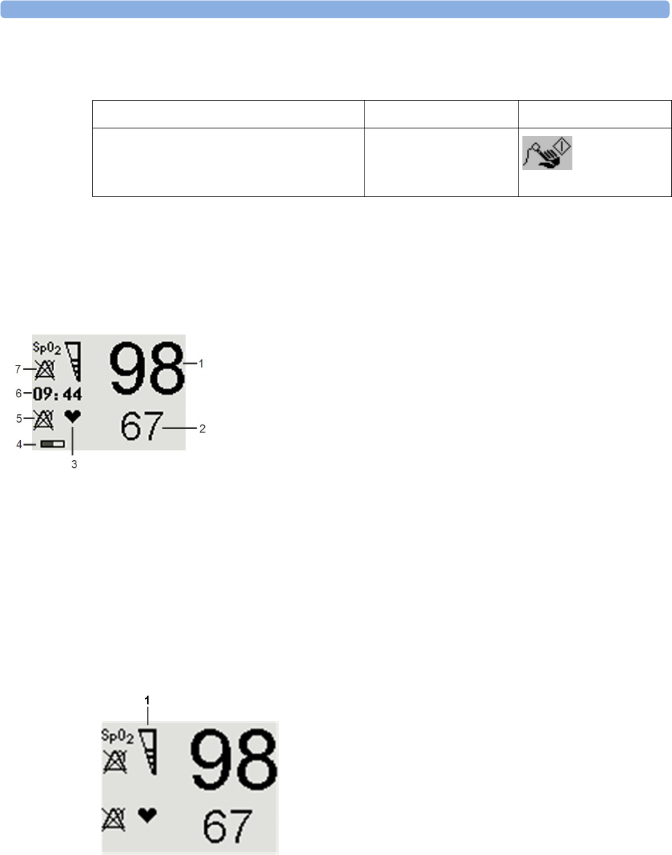
1SpO2 numeric
2Pulse rate numeric
3Symbol indicating pulse rate
4Measurement mode - indicates here that Auto mode is
active and shows the time to the next measurement.
5Alarms Off symbol for Pulse
6Timestamp
7Alarms Off symbol for SpO2
Note: The Alarms Off symbols indicate that no physiological alarms are available from the Cableless
Measurement Devices when not assigned to a host.
1SpO2 Quality Indicator

2 IntelliVue CL SpO2 Pod
33
Assessing a Suspicious SpO2 Reading
Traditionally, pulse rate from SpO2 was compared with heart rate from ECG to confirm the validity of the
SpO2 reading. With newer algorithms, such as FAST-SpO2, this is no longer a valid criteria because the
correct calculation of SpO2 is not directly linked to the correct detection of each pulse.
When pulse rate is very low, or strong arrhythmia is present, the SpO2 pulse rate may differ from the heart
rate calculated from ECG but this does not indicate an inaccurate SpO2 value.
If you doubt the measured SpO2, use the signal quality indicator (if available) or, when used with a patient
monitor, the pleth wave and perfusion indicator on the monitor to assess the signal quality.
WARNING
With pulse oximetry, sensor movement, ambient light (especially strobe lights or flashing lights) or
electromagnetic interference can give unexpected intermittent readings when the sensor is not attached.
Especially bandage-type sensor designs are sensitive to minimal sensor movement that might occur when
the sensor is dangling.
Changing the Averaging Time
Depending on the monitor configuration, you may be able to change the averaging time for the SpO2
values.
The averaging time represents the approximate time period used for the calculation. The exact averaging
time also depends on the signal conditions. The longer the averaging time, the longer the time needed until
the SpO2 values reflect the physiological event. The same averaging is applied to all numerical values: SpO2,
pulse rate and perfusion (only available at the patient monitor). Fast averaging is useful for situations where
an extremely fast measurement is required or few artifacts are expected. Use slow averaging where you
expect the number of artifacts to be relatively high.
1In the SpO₂ menu, select Average.
2Select the required averaging time from the list.
Perfusion Numeric (only available on the Patient Monitor)
The perfusion numeric (Perf) gives a value for the pulsatile portion of the measured signal caused by the
pulsating arterial blood flow.
You can also use the perfusion numeric as a quality indicator for the SpO2 measurement. Above 1 is
optimal, between 0.3-1 is acceptable. Below 0.3 is marginal; reposition the sensor or find a better site.

2 IntelliVue CL SpO2 Pod
34
Alarms
The IntelliVue Cableless Measurements have two different types of alarm: patient alarms and technical
alarms (INOPs).
Patient Alarms
Patient Alarms are high priority alarms (such as a potentially life threatening situation), also called red
alarms, or medium priority alarms, also called yellow alarms.
Technical Alarms (INOPs)
Technical alarms, also known as INOPs, indicate that the measuring device cannot measure reliably. If an
INOP interrupts monitoring, there will be a question mark in place of the measurement numeric. An INOP
tone sounds at the Cableless Measurement Device only when there is no SRR connection to a host.
Exception: the Battery empty INOP tone sounds also with SRR connection.
Most INOPs are low priority, however there are a small number of INOPs which, due to their severity, are
medium or high priority.
Alarm Delays
There is a delay between a physiological event at the measurement site and the corresponding alarm
indication at the Cableless Measurement Device. This delay has two components:
• The general measurement delay time is the time between the occurrence of the physiological event and
when this event is represented by the displayed numerical values. This delay depends on the algorithmic
processing.
• The time between the displayed numerical values crossing an alarm limit and the alarm indication on
the device is the system alarm delay. The system alarm delay is the processing time the system needs for
any alarm on the Cableless Measurement Device to be indicated after the measurement has triggered
the alarm. This delay depends on the Cableless Measurement Device and the connected host system.
See the performance specifications in the chapter “IntelliVue CL SpO2 Pod Specifications” on
page 133 for the system alarm delay specification of the Cableless Measurement Device.
The alarm delay configured for a specific measurement is normally a fixed time.
Multiple Alarms
If more than one alarm is active, the alarm messages are shown in the alarm status area in succession. An
arrow symbol next to the alarm message informs you that more than one message is active.
The Cableless Measurement Device sounds an audible indicator for the highest priority alarm. If more than
one alarm condition is active in the same measurement, the Cableless Measurement Device announces the
most severe.
NOTE
If you want to use local attended monitoring, make sure to have all Cableless Measurement Devices
upgraded to at least Rev. B.02.
Visual Alarm Indicators
WARNING
• No patient alarms are available on the Cableless Measurement Devices when assigned to a host monitor
(unless they are selected for use in patient transport at the monitor they are assigned to) or
GuardianSoftware.
• Visual patient alarm indicators are disabled on the Cableless Measurement Devices when connected to
a host monitor (unless they are selected for use in patient transport at the monitor they are assigned to)
or GuardianSoftware.
2 IntelliVue CL SpO2 Pod
35
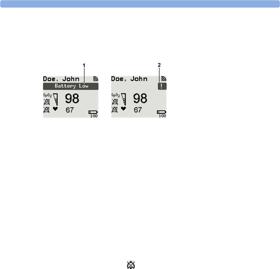
Alarm Message
Alarm messages are displayed in black on a light gray background in the alarm status area at the top of the
screen indicating the source of the alarm and coded according to their severity. If more than one
measurement is in an alarm condition, the message changes every few seconds, and has an arrow ( ) at the
side. The asterisk symbols (*) beside the alarm message match the alarm priority: *** for red alarms, ** for
yellow alarms. Standard INOPs do not have a symbol, red and yellow INOPs have exclamation marks
beside the alarm message: !!! for red INOPs and !! for yellow INOPs.
An alarm message that appears is automatically highlighted. Use the key to silence the message. A Silence
message is displayed at the bottom of the screen and highlighted. Press again to confirm the
acknowledgment of the alarm. After the confirmation, any ongoing alarm message is displayed in the icon
tray of the screen.
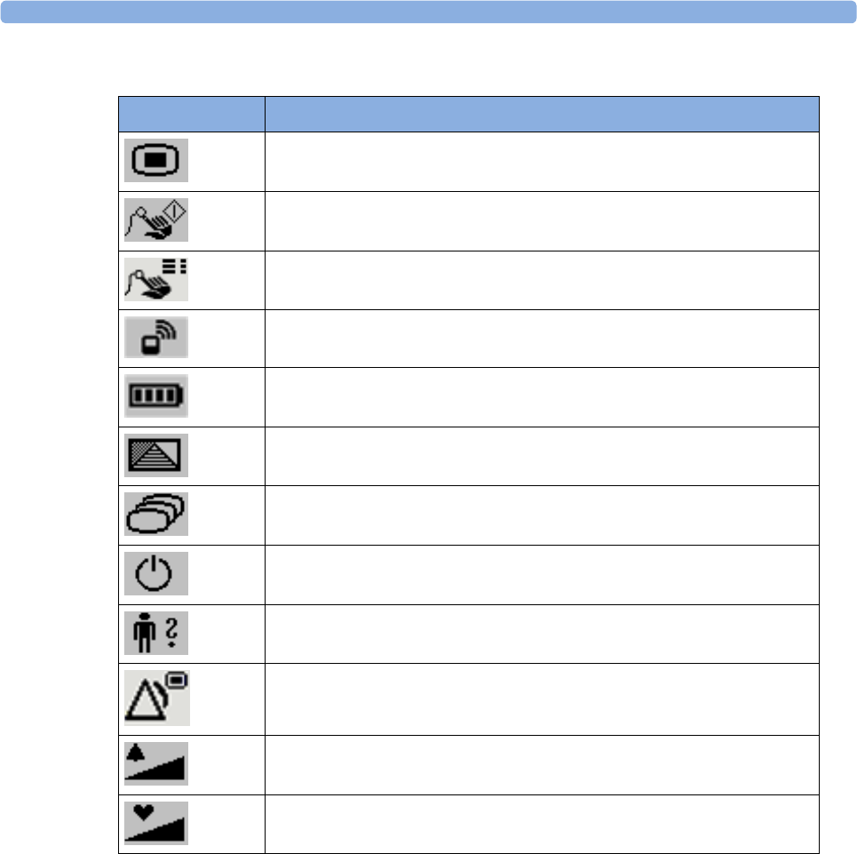
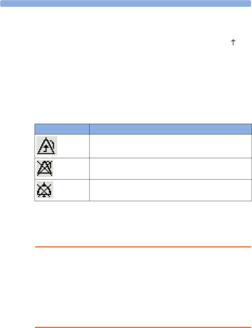
Alarm States
Depending on the alarm state of your Cableless Measurement Device, the following icons may be displayed
on the device:
Audible Alarm Indicators
Audible alarm indicator patterns are repeated until you acknowledge the alarm by switching it off or pausing
it, or until the alarm condition ceases (if audible alarm indication is set to non-latching).
Cableless Measurements Devices alone (without host, e.g. a patient monitor) are not suitable for unattended
monitoring due to their limited alarm volume.
WARNING
• Do not rely exclusively on the audible alarm system for patient monitoring. Adjustment of alarm
volume to a low level or off during patient monitoring may result in patient danger. Remember that the
most reliable method of patient monitoring combines close personal surveillance with correct
operation of monitoring equipment.
• No patient alarms are available on the Cableless Measurement Devices when connected to a host
monitor (unless they are selected for use in patient transport at the monitor they are assigned to) or to
GuardianSoftware.
• When connected to a host monitor or GuardianSoftware, no alarm tones are available on the Cableless
Measurement Devices (unless they are selected for use in patient transport at the monitor they are
assigned to).
Icon Description
No local alarming on Cableless Measurement Device. The device is connected
to a host monitor or telemetry device and has no visual or audible patient alarm
indicators. The device will only display INOP messages.
Alarms are switched off.
Alarm volume is set to 0.
2 IntelliVue CL SpO2 Pod
36
Silencing an Alarm
To silence an alarm, select the alarm message and press the key.
This will silence the alarm tone and clear the alarm message. If the condition which caused the alarm is still
present, the alarm indicator will be displayed in the icon tray of the screen.
When using a Cableless Measurement Pod with an IntelliVue Information Center iX Release A, make sure
to remove the pod at the telemetry device and only when in SRR range of the telemetry device. Otherwise
you will get a technical alarm (cl SpO₂ Disconnect) that can not be silenced at the telemetry device. You will
then have to reboot the telemetry device to remove the message.
Displaying a List of Current Alarms
To display a list of the currently active alarms,
1Select the Alarms SmartKey or Main Setup SmartKey, followed by Alarms.
2Select Alarm Messages.
Setting the Volume of the Alarm Tone
To set the volume for the Alarm tone,
1Select the Alarms SmartKey or Main Setup SmartKey, followed by Alarms.
2Select AlarmVol and select a volume setting. The maximum is 10 and the minimum depends on your
configuration.
If the volume of the Alarm tone is set to zero, the following symbol is displayed on the right icon tray of the
Cableless Measurement Device screen:
NOTE
No Alarm tone will sound at the device as long as it is within the SRR range.
Minimum Volume for No Host Monitoring INOP
If your device is connected to a host monitor, and the connection is interrupted, the INOP message No
Host Monitoring will appear within 30 seconds, accompanied by an INOP tone. To help ensure that this
INOP, and any other active alarm, is not overlooked, the INOP and alarm tones may be configured to have
a minimum volume. In this case, INOP and alarm tones will sound even if the device alarm volume is set to
zero.
1Full length alarm message
2Alarm indicator
2 IntelliVue CL SpO2 Pod
37
Alarm Reminder
If Reminder is configured on your device, you will get an audible reminder of alarm conditions that remain
active after you have silenced the alarm. This reminder may take the form of a repetition of the alarm tone
for a limited time, or an unlimited repetition of the alarm tone (this is the same as a new alarm). Alarm
Reminder is not available for standard, light blue INOPs but for yellow and red INOPs.
In Configuration Mode, you can set the interval between silencing the alarm and sounding the reminder
tone to one, two, or three minutes.
Pausing or Switching Off Alarms
If you want to temporarily prevent alarms from sounding, for example while you are moving a patient, you
can pause alarms. Depending on your device configuration, alarms are paused for one, two, or three
minutes, or infinitely. Infinite alarm pause is equivalent to switching the alarms off.
To view the alarm pause setting chosen for your unit,
1In the SmartKeys Menu select Main Setup, Alarms, then OffDurat.
2Check the setting.
This setting can only be changed in Configuration Mode.
To Pause or Switch Off Alarms
Select the key in the SmartKeys Menu followed by Alarms. Press the hardkey to switch to
Paused. If your device is configured to infinite pause time, selecting this option switches alarms off.
Restarting Paused Alarms
To manually switch on alarm indication again after a pause, select the key again.
Alarm indication starts again automatically after the pause period expires. If the device is configured to stay
paused infinitely, you must select again to restart alarm indication.

2 IntelliVue CL SpO2 Pod
38
Alarm Limits
The alarm limits you set determine the conditions that trigger yellow and red limit alarms. For SpO2, where
the value ranges from 100 to 0, setting the high alarm limit to 100 switches the high alarm off. In these
cases, the alarms off symbol is not displayed.
WARNING
Be aware that the devices in your care area may each have different alarm settings, to suit different patients.
Always check that the alarm settings are appropriate for your patient before you start monitoring.
Adjusting the Alarm Limits
1Select the Alarms SmartKey followed by Alarm Limits (or select Main Setup followed by SpO₂):
2Select High Lim then choose the high alarm limit.
3Select Low Lim then choose the low alarm limit.
WARNING
High oxygen levels may predispose a premature infant to retrolental fibroplasia. If this is a consideration do
NOT set the high alarm limit to 100%, which is equivalent to switching the high alarm off.
Adjusting the Desat Limit Alarm
The Desat alarm is a high priority (red) alarm notifying you of potentially life threatening drops in oxygen
saturation.
1In the SpO₂ menu, select DesatLim.
2Adjust the limit.
Setting Up Tone Modulation
Only when the Cableless Measurement Device is not connected to a host:
If tone modulation is on, the pulse tone pitch lowers when the SpO2 level drops.
Select Main Setup followed by User Interface. In this menu, select Tone Modulation to switch between Yes
(for on) and No (for off).
NOTE
If the SpO2 level drops below 52%, two short tones will be issued rather than one long tone.
Latching Alarms
The alarm latching setting for your device defines how the alarm indicators behave when you do not
acknowledge them. When alarms are set to non-latching, their indicators end when the alarm condition
ends. Switching alarm latching on means that visual and/or audible alarm indications are still displayed or
announced by the device after the alarm condition ends. The indication lasts until you acknowledge the
alarm.

2 IntelliVue CL SpO2 Pod
39
Viewing the Alarm Latching Settings
To see the alarm latching setting for your device,
1In the Main Setup menu, select Alarms.
2Here you can see the Visual Latching and Audible Latching settings.
This setting can only be changed in Configuration Mode. You should be aware of the settings chosen for
your unit. There are three possible choices each for visual and audible latching, red only, red and yellow, and
off. These choices can be combined to give the following settings:
Alarm Latching Behavior
All INOPs are non-latching.
Testing Alarms
When you switch the CL SpO2 Pod on, a selftest is started. You must check that the backlight switches on,
and that you hear a single tone. This indicates that the alarm indicators are functioning correctly. For further
testing of individual measurement alarms, perform the measurement on yourself or use a simulator. Adjust
alarm limits and check that appropriate alarm behavior is observed.
Alarm Behavior at Power On
If the device is switched off (Standby), all alarm settings are maintained. If the device is switched off
completely (Power Off), or the battery is completely empty, resulting in complete power loss, all alarm
settings will be lost unless they were actively saved by storing the active profile before the device was
switched off. See “Switching the Device Off” on page 17 and “Using Profiles” on page 18 for details.
When the device is switched back on from either state, it will start in Profile A and you may have to switch
to the desired profile which contains your alarm settings.
After any of these situations, you should check that the alarm settings are appropriate for your patient and
monitoring situation, and if necessary, select the correct profile and patient category.
Visual Latching Audible Latching
Red&Yellow Red&Yellow
Red&Yellow Red Only
Red&Yellow Off
Red Only Red Only
Red Only Off
Off Off
Red & Yellow Measurement
Alarms
Non-latching alarms Visual and audible latching Visual latching, audible
non-latching
Alarm has not
been
acknowledged.
Alarm condition
still present.
Alarm tone on. Alarm message. Alarm tone on. Alarm
message.
Alarm tone on. Alarm
message.
Alarm condition
no longer present.
All audible and visual alarm
indicators automatically stop.
Alarm tone on.
Alarm message.
Alarm message.
Audible alarm indicators
automatically stop.
Alarm has been
acknowledged.
Alarm condition
still present.
All audible and visual alarm
indicators automatically stop.
All audible and visual alarm
indicators automatically stop.
All audible and visual alarm
indicators automatically stop.
Alarm condition
no longer present.
Audible and visual alarm
indicators automatically stop.
Audible and visual alarm
indicators automatically stop.
Audible and visual alarm
indicators automatically stop.

2 IntelliVue CL SpO2 Pod
40
Reference List of Patient Alarms
Reference List of all INOPs
Alarm Message, Indication Source Condition
*** Brady (Pulse) SpO2The heart rate from the Pulse signal has fallen below the
bradycardia limit.
*** Desat SpO2The SpO2 value has fallen below the desaturation alarm
limit.
** Pulse High SpO2The pulse rate has exceeded the high alarm limit.
** Pulse Low SpO2The pulse rate has dropped below the low alarm limit.
** <SpO₂ Label> High SpO2The arterial oxygen saturation has exceeded the high alarm
limit.
** <SpO₂ Label> Low SpO2The arterial oxygen saturation has dropped below the low
alarm limit.
*** Tachy (Pulse) SpO2The Pulse Rate from the Pleth signal has exceeded the
tachycardia limit
INOP Message, Indication Source What to do
Batt Incompatible
INOP tone
Battery Battery cannot be used with this Cableless Measurement
Device. Replace battery with one that has been approved for
use with this Cableless Measurement Device. Contact your
service personnel.
Batt Malfunction
INOP tone
Battery Malfunction of the battery system detected (charger circuit
or battery). Contact your service personnel.
Battery Empty
INOP tone
Battery The remaining monitoring time is below 30 minutes. Charge
battery.
Battery Low
INOP tone
Battery The remaining monitoring time is below 2 hours.
Check Batt Temp
INOP tone
Battery The temperature of the battery is critically high. Check that
Cableless Measurement Device is not covered and not
exposed to a heat source. If INOP persists, remove
Cableless Measurement Device from patient and contact
your service personnel.
Check Battery
INOP tone
Battery The maximum number of charge/discharge cycles of the
battery will be reached in less than 50 cycles. Contact your
service personnel to replace the battery.
Check Charger I/F
INOP tone
Battery Overvoltage or undervoltage detected at the charger
interface. Clean contacts of charger interface at Cableless
Measurement Device and charging station. If the INOP
persists, contact your service personnel.

2 IntelliVue CL SpO2 Pod
41
cl SpO₂ Chk Sett
INOP tone
Cableless Measurement
Device
If this INOP appears and an INOP tone sounds, check the
Cableless Measurement Device and patient settings before
you resume making measurements. If the settings are
unexpected, there may be a problem with the Cableless
Measurement Device software. Contact your service
personnel.
If this INOP is acknowledged at the Cableless Measurement
Device, it is cleared. If it is silenced remotely, only the tone is
cleared.
cl SpO₂ Disconnect
only at the host
Cableless Measurement
Device
The SpO2 Pod has lost the SRR connection to the telemetry
device or the patient monitor.
No Host Monitoring
INOP tone
Cableless Measurement
Device
There is a problem with the communication to the assigned
patient monitor or telemetry device and monitoring is
currently not possible (no patient alarms or information).
Check the connection. Contact your service personnel.
No System Cableless Measurement
Device
There is a problem with the communication to the assigned
IntelliVue GuardianSoftware and monitoring is currently
not possible (no patient alarms or information). Check the
connection. Contact your service personnel.
Remove From Pat
INOP tone
Cableless Measurement
Device
Displayed on the Cableless Measurement Device. The
temperature of the battery is too high. Remove the Cableless
Measurement Device from the patient and contact service
personnel.
Service Battery
INOP tone
Battery Maximum number of charge/discharge cycles for battery
exceeded. Charging of the battery is inhibited. Contact your
service personnel to replace battery.
<SpO₂ Label> Equip Malf
Numeric is replaced by -?-
INOP tone
SpO2The SpO2 Pod is faulty. Contact your service personnel.
<SpO₂ Label> Erratic
Numeric is replaced by -?-
INOP tone
SpO2Check the sensor placement. Try another adapter cable and
sensor. If the INOP persists, contact your service personnel.
<SpO₂ Label> Extd.Update
Numeric is replaced by -?-
SpO2The update time for displayed values is extended due to an
NBP measurement on the same limb or an excessively noisy
signal.
<SpO₂ Label>Interference
Numeric is replaced by -?-
INOP tone
SpO2There is too much interference, caused by a high level of
ambient light and/or electrical interference. Cover the
sensor to minimize ambient light. If the INOP persists,
make sure that the sensor cable is not damaged or
positioned too close to power cables.
<SpO₂ Label> Low Perf
Numeric is replaced by -?-
SpO2Accuracy may be compromised due to very low perfusion.
Stimulate circulation at sensor site. If INOP persists, change
the measurement site.
<SpO₂ Label> NeoPatient?
Numeric is replaced by -?-
INOP tone
SpO2The patient monitor the SpO2 Pod is assigned to is in
neonatal mode. The INOP will remain active until the
monitor is changed to adult or pediatric mode.
INOP Message, Indication Source What to do

2 IntelliVue CL SpO2 Pod
42
<SpO₂ Label> No Pulse
Numeric is replaced by -?-
INOP tone
SpO2Check the perfusion at the measurement site. If necessary,
stimulate circulation or change the measurement site. If the
INOP is due to an NBP measurement on the same limb,
wait until the NBP measurement is finished.
<SpO₂ Label> No Sensor
Numeric is replaced by -?-
INOP tone
SpO2Make sure the SpO2 sensor is connected. If the INOP
persists, try another sensor. If you acknowledge this INOP,
the measurement will be switched off.
<SpO₂ Label> NoisySignal
Numeric is replaced by -?-
INOP tone
SpO2Excessive patient movement or electrical interference is
causing irregular pulse patterns. Try to reduce patient
movement or to relieve the cable strain on the sensor.
<SpO₂ Label> Poor Signal SpO2The signal quality of the SpO2 measurement is poor. The
accuracy may be compromised.
<SpO₂ Label> Pulse?
Numeric is replaced by -?-
INOP tone
SpO2The detectable pulsations of the SpO2 signal are outside the
specified pulse rate range.
<SpO₂ Label> Searching
Numeric is unavailable
SpO2The patient signal is analyzed, but no valid numerics are
available yet.
<SpO₂ Label> Sensor Malf
Numeric is replaced by -?-
INOP tone
SpO2The SpO2 sensor is faulty. Try another sensor. If the INOP
persists, contact your service personnel.
<SpO₂ Label> Sensor Off
Numeric is replaced by -?-
INOP tone
SpO2The algorithm has determined that a sensor is connected,
but not properly applied to the patient. The ability of the
algorithm to detect this condition depends on the used
sensor type.
<SpO₂ Label> Unkn.Sensor
Numeric is replaced by -?-
INOP tone
SpO2The connected SpO2 sensor is not supported by this
measurement hardware.
<SpO₂ Label> Upgrade
Numeric is replaced by -?-
SpO2SpO2 in upgrade mode, no patient monitoring possible.
INOP Message, Indication Source What to do

2 IntelliVue CL SpO2 Pod
43
Local Attended Monitoring
When working with an IntelliVue MP5, MP5SC, MP5T Patient Monitor with software revision J.2 or higher
as a host, or with an IntelliVue X2 Multi-Measurement Module with software revision K.2 or higher, the
IntelliVue CL SpO2 and NBP Pods can be used for local attended monitoring. This is for situations where
you want to have alarm indications at the CL Pods when they are out of reach of the patient monitor
(disconnected). The patient monitor setting to switch CL Measurement Alarms on and off (cl Alarms On/
Off) is used to enable and disable this functionality. As a default, the CL Measurement Alarms are on.
Local Attended Monitoring Enabled
By default, the patient monitor is set to receive alarms from the CL Pods (can only be changed in
configuration mode). This scenario is used for patients who require uninterrupted monitoring. The various
alarms from the CL Pods are indicated at the patient monitor if they are enabled at the monitor. When the
CL Pod is disconnected from the patient monitor and the caregiver has activated the transport mode at the
monitor, physiological alarms are indicated locally at the CL Pod. A cl SpO₂ Disconnect INOP is shown at
the monitor if the SRR connection is lost and the transport mode has not been activated.
CL Pod connected to a patient monitor and CL Measurement Alarms On (Standard Use Model):
CL Pod disconnected from patient monitor and CL Measurement Alarms On, Local Attended
Monitoring:
SRR connection
At the CL Pod:
Indication of technical
alarms only
At the monitor:
Indication of physiological and
technical alarms from CL Pods
No SRR connection
At the CL Pod:
Indication of technical and
physiological alarms
At the monitor:
No indication of physiological
alarms from CL Pods. No
indication of technical alarms
after disconnection.
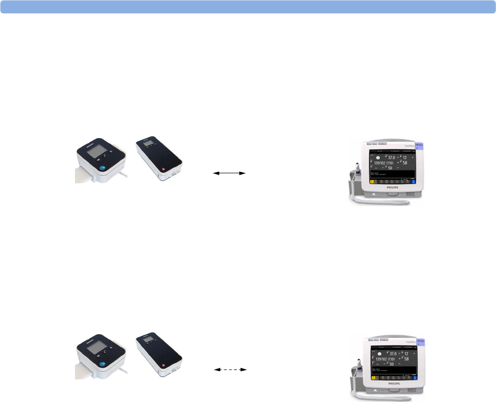
2 IntelliVue CL SpO2 Pod
44
Local Attended Monitoring Disabled
The patient monitor is set to cl Alarms Off (this can only be done in configuration mode). This scenario is
used if the patients do not require permanent monitoring and are mobile, but vital signs are taken from time
to time. All alarms from the CL Pods are switched off at the monitor. If the SRR connection is lost, no cl
SpO₂ Disconnect INOP is shown at the monitor in this scenario.
CL Pod connected to a patient monitor and CL Measurement Alarms Off:
CL Pod disconnected from patient monitor and CL Measurement Alarms Off:
SRR connection
At the CL Pod:
Indication of technical
alarms only
At the monitor:
No indication of physiological
alarms from CL Pods.
Indication of technical alarms
from CL Pods.
No SRR connection
At the CL Pod:
Indication of technical
alarms only
At the monitor:
No indication of physiological
and technical alarms from CL
Pods.

2 IntelliVue CL SpO2 Pod
45
Alarm Availability: Standard Use Model versus Local Attended Monitoring with CL
Measurement Alarms On
12
Standard Use Model Local Attended Monitoring
->
Caregiver activates
'Use for transport'
<-
Caregiver activates
'Use with monitor'
SRR connection no SRR connection
Action / Event Situation Alarm Availability
at CL Pod
Alarm Availability
at Patient Monitor
Standard Use Model:
normal operation,
no special action
CL Pod connected to the
patient monitor (1)
Technical alarms
(own)
No physiological alarms
No Local Alarming icon is
displayed:
Technical alarms
(own + from Pod)
Physiological alarms
(own + from Pod)
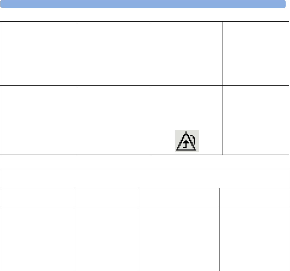
2 IntelliVue CL SpO2 Pod
46
Activation of Local Attended
Monitoring:
Caregiver activates Local
Attended Monitoring and
disconnects CL Pod temporarily
by setting Use for Transp. in the
Patient Monitor's Equipment
window
Patient is in transport without
connection to the host system,
caregiver attends the patient
(2)
Technical alarms
(own)
Physiological alarms
(own)
Technical alarms
(own)
Physiological alarms
(own)
No alarms from CL Pod
Deactivation of Local
Attended Monitoring:
Caregiver deactivates Local
Attended Monitoring and
reconnects CL Pod to a patient
monitor by setting Use with
Monitor in the patient monitor's
Equipment window
Patient returns from
transport.
Back to the standard use
model (1)
Technical alarms
(own)
No physiological alarms
No Local Alarming icon is
displayed:
Technical alarms
(own + from Pod)
Physiological alarms
(own + from Pod)
Special Case:
Connection lost while in Standard Use Model
Action / Event Situation Alarm Availability
at CL Pod
Alarm Availability
at Patient Monitor
Alternative Use Model:
CL Pod temporarily
disconnected from a monitor
due to unintentional loss of
connection (e.g. out of range),
Local Attended Monitoring
has not been activated by the
caregiver
No Host Monitoring INOP
at CL Pod
cl SpO₂ Disconnect INOP
at patient monitor
Local Attended
Monitoring is
automatically activated (2)
Technical alarms
(own)
Physiological alarms
(own)
Technical alarms
(own)
Physiological alarms
(own)
No alarms from CL Pod

2 IntelliVue CL SpO2 Pod
47
Alarm Availability: Standard Use Model versus Local Attended Monitoring with CL
Measurement Alarms Off
34
Patient within Range Patient Mobile
->
Patient mobile
<-
Patient back
SRR connection no SRR connection
Action / Event Situation Alarm Availability
at CL Pod
Alarm Availability
at Patient Monitor
Connected, but no CL Alarms
(CL Measurement Alarms
Off):
normal operation,
no special action
CL Pod connected to the
patient monitor (3)
Technical alarms
(own)
No physiological alarms
No Local Alarming icon is
displayed:
Technical alarms
(own + from Pod)
Physiological alarms
(own)

2 IntelliVue CL SpO2 Pod
48
Patient is leaving the vicinity
of the monitor:
no special action
Patient is mobile without
connection to the host system
(4)
Technical alarms
(own)
No physiological alarms
Alarms Off icon is displayed
in front of each numeric:
Technical alarms
(own)
Physiological alarms
(own)
No alarms from CL Pod
Patient returns to the vicinity
of the monitor:
no special action
Patient returns.
Back to connected status (3)
Technical alarms
(own)
No physiological alarms
No Local Alarming icon is
displayed:
Technical alarms
(own + from Pod)
Physiological alarms
(own + from Pod)

2 IntelliVue CL SpO2 Pod
49
SpO2 Default Settings
These are the most important default settings of your IntelliVue CL SpO2 Pod as they are delivered from
the factory. For a comprehensive list and explanation of default settings, see the Configuration Guide
supplied with your devices. The default settings can be permanently changed in Configuration Mode. When
the Pod is assigned to a patient monitor, the settings defined at the patient monitor will overwrite the
settings defined at the Pod.
SpO2 Settings Factory Defaults
Adult Pedi Neo
Mode Continuous Continuous Continuous
Repeat Time 15 min 15 min 15 min
Alarms On On On
Pulse Volume 111
ToneMod. Yes Yes Yes
Perfusion OnOnOn
Average 10 sec 10 sec 10 sec
NBP Alarm Suppr. OnOnOn
Aging Time 10 min 10 min 10 min
Color Cyan (light blue) Cyan (light blue) Cyan (light blue)
Average in Mon. No No No
Signal Quality OnOnOn
Label SpO₂SpO₂SpO₂
SpO2 Alarm Default Settings
Setting Adult Pedi Neo
DesatLim 80 80 80
Low Lim 90 90 85
High Lim 100 100 95
Desat Delay 20 sec 20 sec 20 sec
High Alarm Delay 10 sec 10 sec 10 sec
Low Alarm Delay 10 sec 10 sec 10 sec
Pulse Settings Factory Defaults
Adult Pedi Neo
Pulse OnOnOn
Alarms On On On
High Lim 120 160 200
Low Lim 50 75 100
Δ Brady 202020
Brady Clamp 40 40 50

2 IntelliVue CL SpO2 Pod
50
Integrated Battery Handling
Only qualified and authorized service personnel (biomedical engineers or technicians) should change
batteries.
Battery Care
Battery care begins when you receive a new IntelliVue Cableless Measurement Device with built-in battery
and continues throughout the life of the device. The table below lists battery care activities and when they
should be performed.
Handling Precautions
Lithium ion batteries store a large amount of energy in a small package. Use caution when handling the
IntelliVue Cableless Measurement Devices with built-in battery; misuse or abuse could cause bodily injury
and/or property damage.
• Handle with care.
• Do not expose the device to liquids.
• Do not attempt to disassemble the device.
• Do not put device in autoclave.
• Damaged devices should not be used anymore.
WARNING
• Do not crush or puncture - mechanical abuse can lead to internal damage and internal short circuits
which may not be visible externally.
• Do not incinerate the devices or expose them to temperatures above 60°C (140°F).
Δ Tachy 202020
Tachy Clamp 200 220 240
Pulse Settings Factory Defaults
Adult Pedi Neo
Activity When to perform
Perform a visual inspection Before using the IntelliVue Cableless Measurement Device
Charge the battery Upon receipt, after use, or if a low battery state is indicated. To
optimize performance, a fully (or almost fully) discharged
battery should be charged as soon as possible.
Store the device in a state of charge in the
range of 40-50% and power off the device
completely.
When not in use for an extended period of time, or when the
device is shipped.

2 IntelliVue CL SpO2 Pod
51
Storage
If unused IntelliVue Cableless Measurement Devices are stored for an extended period of time:
• they should be powered off for storage
• they should be stored in a cool place, ideally between 15°C and 25°C (60°F and 77°F)
• the state of charge should be between 40 and 50%
• they should be recharged every six months
Storing in a cool place slows the aging process of the batteries. They should be fully charged prior to use.
Do not store the device at a temperature outside the range of -20°C (-4°F) to 60°C(140°F).
Do not store cableless devices in direct sunlight.
NOTE
Storing the devices at temperatures above 40°C (104°F) for extended periods of time could significantly
reduce the battery's life expectancy.
Battery Lifetime Management
The lifetime of a Lithium Ion battery depends on the frequency and duration of use. When properly cared
for, the useful life is approximately 4 years or 400 complete charge-discharge cycles, whichever comes first.
In addition, experience indicates that the incidence of failure may increase with battery service life due to the
accumulated stresses of daily use. We therefore strongly recommend that lithium ion batteries be replaced
after 4 years or 400 complete charge-discharge cycles.
To see the date of manufacture and the number of charge-discharge cycles:
1Select the Battery Smartkey or Main Setup followed by Battery.
2Press the hardkey to view the battery details.
The date of manufacture and the number of charge-discharge cycles are listed with other battery data on the
screen. Use the ◄ hardkey to scroll through the list.
The age of a lithium ion battery begins at the date of manufacture.

2 IntelliVue CL SpO2 Pod
52
Accessories
You can order parts and accessories from Philips supplies at www.medical.philips.com or consult your local
Philips representative for details. Also consult the accessories' Instructions for Use, if available.
WARNING
Reuse: Never reuse single-patient sensors, accessories and so forth that are intended for single use, or
single patient use only. Reuse may compromise device functionality and system performance and cause a
potential hazard, in particular with regard to cross-contamination.
Philips’ approval: Use only Philips-approved accessories. Using non-Philips-approved accessories may
compromise device functionality and system performance and cause a potential hazard.
Accessories Compliant with EMC Standards
All accessories listed in the accessories sections comply, in combination with the IntelliVue Cableless
Measurements, with the requirements of IEC 60601-1-2.
IntelliVue CL SpO2 Pod Accessories
All listed sensors operate without risk of exceeding 41°C on the skin, if the initial skin temperature does not
exceed 35°C.
Make sure that you use only the accessories that are specified for use with this device, otherwise patient
injury can result.
1 May not be available in all geographies
Part Number Description Contents
989803165941 Mobile CL 20 single patient SpO2 Sensors and
Cradles for use on pediatric and adult patients
>10 kg
20 Single-Patient Mobile CL DSpO2-1A Sensors
20 Single-Patient Wristbands
20 Single-Patient Cradles
pre-assembled
989803165921 Mobile CL 20 single patient SpO2 Sensors for
use on pediatric and adult patients >10 kg
20 Single-Patient Mobile CL DSpO2-1A Sensors
9898031659311Mobile CL reusable SpO2 Sensor and Cradles
for use on pediatric and adult patients > 15 kg
1 Reusable Mobile CL RSpO2-1A Sensor
20 Single-Patient Cradles with pre-attached
Wristbands
989803165951 Mobile CL 20 SpO2 Cradles (single patient) 20 Single-Patient Cradles with pre-attached
Wristbands
989803165961 Mobile CL 50 SpO2 Wristbands (single
patient)
50 Single-Patient Wristbands
989803168861 Mobile CL SpO2 Battery Kit 1 Battery
1 disassembly tool
1 front housing

2 IntelliVue CL SpO2 Pod
53
Maintenance and Troubleshooting
WARNING
Schedule: Failure on the part of the responsible individual hospital or institution employing the use of this
equipment to implement a satisfactory maintenance schedule may cause undue equipment failure and
possible health hazards.
Contact: If you discover a problem with any of the equipment, contact your service personnel, Philips, or
your authorized supplier.
Inspecting the Equipment and Accessories
You should perform a visual inspection before every use, and in accordance with your hospital's policy.
With the device switched off:
1Examine unit exteriors for cleanliness and general physical condition. Make sure that the housings are
not cracked or broken, that everything is present, that there are no spilled liquids and that there are no
signs of abuse.
2Inspect all accessories (cables, sensors and so forth). If any show signs of damage, do not use them.
WARNING
If the IntelliVue Cableless Measurement Device is mechanically damaged, or if it is not working properly,
do not use it for any monitoring procedure on a patient, contact your service personnel.
Maintenance Task and Test Schedule
All maintenance tasks and performance tests are documented in detail in the service documentation
supplied on the IntelliVue Cableless Measurements documentation DVD. These tasks are for Philips-
qualified service professionals only.
Ensure that these tasks are carried out as indicated by the device's maintenance schedule, or as specified by
local laws. Contact a Philips-qualified service provider if your device needs a safety or performance test.
Clean and disinfect equipment to decontaminate it before testing or maintaining it.
Troubleshooting
If a device will not switch on when you press a key, place it onto a charger slot on the charging station.
If you suspect a problem with an individual measurement device, read the Instructions for Use and
double check that you have set up the measurement correctly. Check also that the measurement has not
been switched off at the patient monitor that the device is assigned to.
If you suspect an intermittent, system-wide problem call your service personnel.

2 IntelliVue CL SpO2 Pod
54
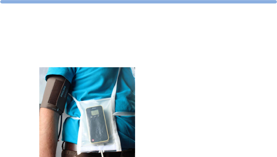
3
55
3IntelliVue CL NBP Pod
To measure NBP, you need Philips standard cuffs, a Mobile CL NBP Cradle and a pouch and extension air
hose, or a Mobile CL NBP Cradle and Mobile CL Cuffs. When using Mobile CL Cuffs, the cradle is used to
attach the Pod to the cuffs and to allow easy removal of the Pod.
Standard Philips cuffs and specialized single-patient and reusable NBP cuffs are available for use with the
IntelliVue CL NBP Pod. For details regarding the cuffs and single-patient cradle, refer to “IntelliVue CL
NBP Pod Accessories” on page 94.
General Operation of the NBP Pod
The following sections describe operation on the NBP Pod itself. For operation from a patient monitor, see
“Controls Available with a Patient Monitor” on page 67. For operation from an Information Center via a
telemetry system, see “Controls Available with a Telemetry Device” on page 68. For operation with
IntelliVue GuardianSoftware, see “Controls Available with GuardianSoftware” on page 68.
The NBP Pods have three hardkeys for basic operation and a set of configurable SmartKeys which appear
on the screen. These are used to activate and navigate through the on-screen menus and to select individual
items. The typical operator's position is such that everything on the device's display can be read clearly and
easily.
Switching the Devices On
The first time an NBP Pod is used, or after the device has been powered off for storage, place it on the
IntelliVue CL Charging Station. This will automatically switch the device on.
If the NBP Pod has only been switched off temporarily (see “Switching the Device Off” on page 17), press
any hardkey to turn the device on again.
When an NBP Pod is not operated, it will automatically switch off the screen lighting after a short time. A
little later the low-activity screen will be displayed.
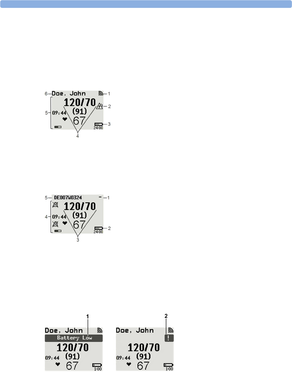
3 IntelliVue CL NBP Pod
56
Screen Layout
There are three variations of the Main Screen layout depending on the Alarm status and the general activity
level.
Standard Layout
Alarm Layout
If an alarm occurs the full alarm message appears at the top of the screen. After the alarm message has been
silenced the alarm indicator is shown as a symbol on the right side of the screen.
When assigned to a monitor, telemetry device or a patient in GuardianSoftware:
1Connection status indicator
2Indicator that alarming capability has been transferred to
the host (to the monitor or, for the telemetry device, to
the Information Center). No patient alarms will be
announced on the Cableless Measurement Device.
3Battery indicator
4Measurement values
5Measurement-related symbols (see the “Monitoring
NBP” section for details)
6Patient identification
When not assigned to a monitor or telemetry device:
1Connection status indicator
2Battery indicator
3Measurement values
4Measurement-related symbols (see the “Monitoring
NBP” section for details). The Alarms Off symbols
indicate that no physiological alarms are available from
the Cableless Measurement Devices when not assigned
to a host.
5Cableless Measurement Device equipment label
1Full length alarm message
2Alarm indicator

3 IntelliVue CL NBP Pod
57
Low-Activity Screen
If the Cableless Measurement Device has not been operated for a while, the screen lighting will switch itself
off and a little later the screen will switch to a pre-configured "low-activity" screen.
When a Cableless Measurement Device Cannot be Activated
If you cannot activate a device by pressing a key, place it on the IntelliVue CL Charging Station. The device
becomes active. Check the battery status. If necessary, leave the device on the charger until the battery is
fully charged.
Using the Hardkeys
The IntelliVue Cableless Measurement Devices have three hardkeys: ◄, , ►.
Use ◄ and ► to navigate through SmartKeys and menus and to select items or to silence alarms.
The three hardkeys also have an additional function when the key is held down for a couple of seconds:
Using the SmartKeys
A SmartKey is a graphical key which appears on the screen and gives you fast access to functions.
SmartKeys Menu
Press the hardkey (without any screen element highlighted) to get to the SmartKeys menu.
Use the ◄ and ► hardkeys to move along the row of SmartKeys. The highlighted SmartKey is displayed in
full above the row of SmartKeys. When you use the ◄ or ► hardkey at the end of the row, an Exit screen
appears and then with further presses you move on to the next page of SmartKeys. To leave the SmartKeys
menu you can use the Exit screen or press the ► hardkey for a couple of seconds to return to the Main
Screen.
When the required SmartKey is highlighted, press the key to activate the corresponding function.
To get to the next page of the SmartKeys menu, highlight the rightmost SmartKey then press the ► key.
◄opens the Add To screen to assign a device (or to unassign it when it is already assigned)
opens the SmartKeys menu
►returns to the Main Screen. If already on the Main Screen, it locks the keys and a lock symbol
appears on the screen above the battery symbol. If keys are already locked, it unlocks the keys and
the lock symbol disappears
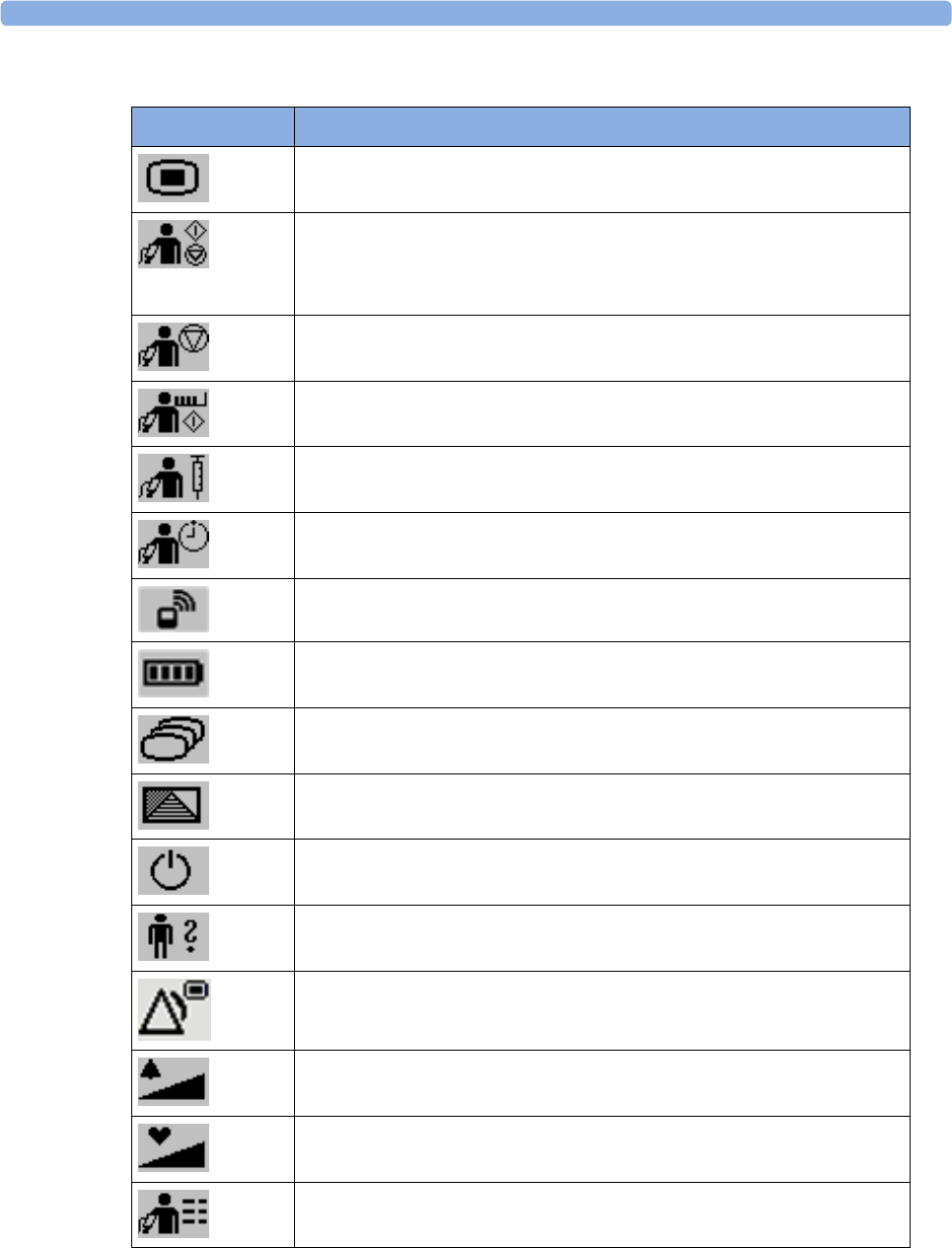
3 IntelliVue CL NBP Pod
58
List of Available SmartKeys
SmartKey Text Labels
Main Setup
- start/stop manual NBP measurement
- start auto series
- start measurement sequence
- stop current automatic measurement within series
stop any NBP measurement and measurement series
start NBP STAT measurement
start venipuncture (inflate cuff to subdiastolic pressure)
set the NBP repetition time
Add/Remove device
enter Battery menu
change Screen
enter Profiles menu
put the device in standby mode (or power off when pressed for more than two
seconds)
enter Patient menu
enters the Alarms menu to access: Alarm Messages, Alarm Limits, Alarms On/
Off/Pause, Alarm Volume.
change alarm volume
change pulse tone volume
access NBP mode selection and setup, with direct start/stop function

3 IntelliVue CL NBP Pod
59
Using the Main Setup Menu
In addition to the hardkeys and SmartKeys for the most needed functions, the Main Setup menu gets you to
all settings that can be adjusted for the respective device. Select the Main Setup SmartKey to get to the Main
Setup menu.
Switching the Device Off
To put the device in standby mode, select the Standby SmartKey, then Confirm.
If you keep Standby pressed for more than two seconds, you can choose between Standby or Power Off.
•Standby means that the display is switched off and the measurements are disabled. Use this option if
your device is not used temporarily. Press any hardkey to turn the device on again.
•Power Off means that the device is switched off completely and can only be switched on again by
putting it on a charger. Use this option when the device is not used for a longer time or prepared for
storage or shipping.
Auto Standby and Auto Power Off
The device can be configured to automatically go into standby mode after a configurable time span of
inactivity. When in standby mode, the device can be automatically powered off after a configurable time
span. See the IntelliVue Cableless Measurements Configuration Guide for details on how to configure these
settings.
Operating Modes
Your device has four operating modes. Some are passcode protected.
•Monitoring Mode: This is the normal, every day working mode that you use for making
measurements. You can change elements such as measurement modes, patient category and so forth.
When you remove the patient from the device, these elements return to their default values. Changes
can be stored permanently only in Configuration Mode. You may see items, such as some menu
options, that are visible but 'grayed out' so that you can neither select nor change them. These are
present for your information only and can be changed only in Configuration Mode.
•Demonstration Mode: Passcode protected, this is for demonstration purposes only. You must not
change into Demonstration Mode during monitoring.
•Configuration Mode: Passcode protected, this mode is for personnel trained in configuration tasks.
These tasks are described in the Configuration Guide. During installation the Cableless Measurement
Device is configured for use in your environment. This configuration defines the default settings you
work with when you switch on.
•Service Mode: Passcode protected, this is for trained service personnel.
Main Setup
NBP
Alarms
Patient
Equipment
User Interface
Standby
Profiles
Operating Modes
Date, Time
Battery
Revisions

3 IntelliVue CL NBP Pod
60
When you switch the device on, it starts up in monitoring mode. To change to a different mode:
1Use the Main Setup SmartKey to get to the Main Setup menu.
2Select Operating Modes and choose the mode you require.
Standby Mode
The IntelliVue Cableless Measurement Devices do not have standby mode. However, when connected to a
monitor that is in standby mode, the IntelliVue Cableless Measurement Device will show a standby screen.
Using the Patient Menu
The Patient menu allows you to see patient demographics information and to remove a patient from a
device. Patient Demographic information is only displayed if the Cableless Measurement Device is assigned
to a patient monitor or GuardianSoftware. Patient Category is the only item of patient data which can be
changed at the Cableless Measurement Device, but only when the device is not assigned to a patient
monitor or telemetry device.
Displaying the Patient Menu
To display the Patient menu,
• select the Patient SmartKey, or
• select the Main Setup SmartKey followed by Patient.
Stop Using a Device for a Patient
To remove a patient from the Cableless Measurement Device,
•in the Patient menu select Free Device.
All patient data is cleared, settings are reset to the defaults and the device is removed from the monitor or
telemetry device.
NOTE
Depending on your configuration, when the device is put on the charger, patient data will also be cleared
and the device will be free for another patient.
Using the Device for a New Patient
To use a device for a new patient,
•in the Patient menu, select New Patient.
If the device was not free, the existing data will be deleted and the profile set to the default.
Using Profiles
A profile is a set of measurement and general settings which have been customized for a particular purpose.
The Cableless Measurement Devices can have four different profiles configured to your requirements. The
default profile is marked with a symbol.
To select a different profile,
1Select the Profiles SmartKey or the Main Setup SmartKey followed by Profiles.
2Select the required profile from the list.
Selecting New Patient or Free Device will always reset the profile to the default.

3 IntelliVue CL NBP Pod
61
Setting the Date and Time
If the Cableless Measurement Device is assigned to a patient monitor, telemetry device or
GuardianSoftware, the date and time will be taken from the host. If this is not the case, you can set the date
and time on the Cableless Measurement Device,
1Select the Main Setup SmartKey and then Date, Time.
2Enter the data for date and time one after another.
3Select Store Date, Time.
If the time has not been set, --:-- will display on the device.
Battery Status
The IntelliVue CL NBP Pods show their battery status on their display both in operating and charging
condition. The battery status indicator is located in the lower right corner of the screen during operation
and in the middle of the screen during charging.
Battery Status Menu
Select the Battery SmartKey or Main Setup followed by Battery using the ◄ and ► keys, then press the
key to open the Battery menu. The Battery menu provides the following information: full-charge and
remaining capacity, voltage, current and temperature.

3 IntelliVue CL NBP Pod
62
Connection with Host Systems
The following sections describe how the IntelliVue Cableless Measurement Devices work together with
host systems (Patient Monitors, Fetal Monitors, Telemetry Devices / Information Center or
GuardianSoftware).
IntelliVue Cableless Measurements Use Models
With these patient-worn measurement devices you can measure and transmit a patient's vitals regularly or
on an intermittent data collection basis. There are four typical use models:
With a Patient Monitor
The IntelliVue Cableless Measurement Devices can be used together with an MP5/MP5SC/MP5T, MP2 or
X2 patient monitor (with an SRR interface). They can communicate their measurement values via short
range radio to the monitor. The monitor may be assigned to a patient sector at the IntelliVue Information
Center (IIC). When assigned to the Information Center, certain actions can be performed at both the
patient monitor and the Information Center. See the table “Controls Available with a Patient Monitor” on
page 67.
In situations where patients are becoming more mobile (for example, in step-down/intermediate care units)
the lightweight Cableless Measurement Devices allow increased mobility within the short range radio range,
without giving up vital signs monitoring.
When assigned to a patient monitor, the Cableless Measurement Device can be selected for use in patient
transport at the patient monitor (for details see the Patient Monitor Instructions for Use). In this case, the
Cableless Measurement Device will perform local attended monitoring. The patient must be attended by
a caregiver during transport, to ensure that alarms on the Cableless Measurement Device are recognized. In
local attended monitoring mode, an alarm message text appears in the alarm status area at the top of the
screen indicating the source of the alarm and an alarm tone is issued. See “Alarms” on page 34 for details.
A telemetry device can be assigned to a patient monitor equipped with short range radio at the same time as
any Cableless Measurement Devices are also assigned to this monitor.
When assigned to a patient monitor, the admitted patient name is displayed on the NBP Pod.
If the connection between the monitor and the Cableless Measurement Device is lost, an INOP will be
displayed at the monitor: cl NBP Disconnect. A No Host Monitoring INOP will be displayed on the NBP
Pod, and an INOP tone will sound. In this case, visual and audible alarms are still available at the NBP Pod,
but it is not possible to change the alarm settings.
With a Fetal Monitor
In combination with an Avalon CL Transducer System, the IntelliVue CL NBP Pod can be used together
with an Avalon FM 20-50 Fetal Monitor. The NBP Pods are assigned to the fetal monitor by docking them
at the Avalon CL Base Station. For information about Avalon Fetal Monitors, the Avalon CL Transducer
System and the Avalon CL Base Station, please refer to the Avalon Fetal Monitor Instructions for Use.
With a Telemetry Device
The Cableless Measurement Devices can be assigned to a patient with the telemetry device TRx4841A/
TRx4851A or an MX40 wearable patient monitor. They can communicate their measurement values via
short range radio to the telemetry device which communicates them to an IntelliVue Information Center to
provide a consolidated set of patient values.
Some of the measurement tasks can be performed remotely from the Information Center. See the table
“Controls Available with a Telemetry Device” on page 68.
If the patient name is available at the Information Center, it will be also displayed on the NBP Pod.

3 IntelliVue CL NBP Pod
63
When a Cableless Measurement Device is assigned to a telemetry device, it is not possible for the telemetry
device to be wirelessly assigned or directly connected to a patient monitor.
If the connection between the telemetry device and the Cableless Measurement Device is lost, an INOP will
be displayed at the Information Center: cl NBP Disconnect. A No System Monitor. INOP will be displayed
on the NBP Pod, and an INOP tone will sound.
With IntelliVue GuardianSoftware
The Cableless Measurement Devices can be used together with IntelliVue GuardianSoftware.
GuardianSoftware collects non-continuous vital signs data that are transmitted via a Transmitter, Hotspot
or MP5 from the Cableless Measurement Devices. Using the collected data, it provides trending, review,
reporting and notification. The Guardian Early Warning Scoring (Guardian EWS) application provides
basic assessment guidance, helping you to recognize the early signs of deterioration in your patients.
GuardianSoftware is not intended for monitoring in combination with Cableless Measurement Devices.
Some of the measurement tasks can be performed remotely from GuardianSoftware. See the table
“Controls Available with GuardianSoftware” on page 68. GuardianSoftware also manages the patient data.
If the connection between GuardianSoftware and the Cableless Measurement Device is lost, the connection
symbol will be displayed gray at GuardianSoftware. A No System INOP will be displayed on the NBP Pod
(no alarm sound).
If a patient name is available at GuardianSoftware, it will be also displayed on the Pod. Any update of
patient data will be synchronized between the Pods and GuardianSoftware. The only patient management
action available directly at the Pod is Free Device. Selecting Free Device removes the current patient from
the Pod and resets the Pod to the default profile. The Pod is unassigned.
Device Compatibility
The IntelliVue CL NBP Pods require the following software levels in the associated equipment:
• IntelliVue Patient Monitor - Release H.0 or above
• Avalon Fetal Monitor in combination with an Avalon CL Transducer System - Release J.3 or above
• IntelliVue Information Center - Release M or above
• Philips Patient Information Center iX - Release A or above
• Telemetry device TRx4841A/TRx4851A - Revision D.00.22 or above
• MX40 wearable patient monitor - Revision A.0 or above
• IntelliVue GuardianSoftware - Revision A.0 or above
Availability of Patient Alarms
When the IntelliVue CL NBP Pod is used alone, without an assignment to a monitor or telemetry device no
patient alarms will be generated.
When the IntelliVue CL NBP Pod is assigned to a patient monitor or telemetry device and a short range
radio connection exists, alarms may be announced at the patient monitor or the Information Center.
•When assigned to a patient monitor / fetal monitor: Alarm messages will be displayed and audible
alarm indicators sounded at the monitor in the same way and under the same conditions as for its own
measurements. See the Instructions for Use of the patient monitor for details.
If a Cableless Measurement Device that is assigned to a patient monitor is selected for use in patient
transport at the patient monitor, the Cableless Measurement Device will perform local attended
monitoring. See the Instructions for Use of the patient monitor for details on how to do this. The
patient must be attended by a caregiver during transport, to ensure that alarms on the Cableless
Measurement Device are recognized. In local attended monitoring mode, an alarm message text
appears in the alarm status area at the top of the screen indicating the source of the alarm and an alarm
tone is issued. See “Alarms” on page 34 for details.

3 IntelliVue CL NBP Pod
64
•When assigned to a telemetry device: Measurement values sent via the telemetry device to the
IntelliVue Information Center can generate alarms at the Information Center when the values meet the
criteria set there for alarms. The alarms will be announced in the same way as measurements from other
sources. See the Instructions for Use of the Information Center for details.
•When assigned to GuardianSoftware: Measurement values sent via transmitter, hotspot or MP5 to
IntelliVue GuardianSoftware will be visualized in GuardianSoftware. Since IntelliVue GuardianSoftware
is a data management system, no alarms are announced. The IntelliVue Cableless Measurement Devices
will also not generate physiological alarms when connected to IntelliVue GuardianSoftware. See the
Instructions for Use of GuardianSoftware.
Assigning an IntelliVue Cableless Measurement Device to a Host
When an IntelliVue CL NBP Pod is used with a host system (patient monitor, telemetry device or
GuardianSoftware), the Cableless Measurement Device must be assigned to that host system.
The assignment can be done at the CL NBP Pod itself or at the host system (patient monitor or
GuardianSoftware).
WARNING
Always make sure that the applied CL NBP Pod is assigned to the correct patient.
WARNING
Short Range Radio connections are subject to interruption due to interference from other radio sources in
the vicinity, including microwaves, bluetooth devices, WLAN devices (802.11b,g,n) and cordless phones.
Depending on the strength and duration of the interference, the interruption may occur for an extended
period. A loss of connection, due to moving out-of-range, interference, or for other reasons, is indicated
with a No Host Monitoring INOP on the NBP Pod, or a cl NBP Disconnect INOP at the host monitor.
Correct channel configuration is important, refer to the Configuration Guide for details.
Assignment at the Measurement Device
To make an assignment, select:
•the
Add/Remove SmartKey , or
• hold the ◄key pressed.
This opens the Add To menu which lists the available patient monitors and telemetry devices within the SRR
range. In order to save power, the list is only visible for a short time; the menu is automatically closed after
40 seconds.
Telemetry device: A telemetry device must be put into assignment mode by pressing the key on the
telemetry device before it can appear in the list. Pressing the key starts an SRR channel search to find
the clearest channel available. During the search all 4 LEDs will blink once per second. The search will

3 IntelliVue CL NBP Pod
65
take approximately 20-25 seconds. Once a channel is identified, the first LED will light up and blink
once per second to indicate that the telemetry device is ready for assignment.
1Select a patient monitor or telemetry system using the ◄ and ► keys.
If you select a patient monitor, the measurement selection key on that monitor will change to show the
type of measurement device.
2Activate the assignment by pressing the key twice on the measurement device.
The Cableless Measurement Device is assigned to the selected patient monitor or telemetry device. A
telemetry device plays the assignment tone when the assignment is successful. A patient monitor issues
an assignment prompt message.
If the internal measurement in the patient monitor is active (the measurement selection key has a yellow
frame), you will need to confirm that it should be deactivated in favor of the Cableless Measurement Device
you want to assign. To do this:
1Select the measurement selection key on the monitor.
A prompt message appears with the Confirm and Cancel keys.
2Select Confirm to deactivate the internal measurement.
When the Cableless Measurement Device is assigned, the symbol appears on its display indicating that
alarming capability has been transferred to the host (to the monitor or, for the telemetry device, to the
Information Center). No patient alarms will be announced on the Cableless Measurement Device.
To unassign the measurement device from the monitor or telemetry system, select the Add/Remove
SmartKey, then select Remove From. After confirmation the SRR connection is disconnected.
Assignment at the Patient Monitor
Assignment at the Patient Monitor
Prepare the Cableless Measurement Device for assignment by activating the Add/Remove SmartKey.
At the patient monitor,
1Select the Measurement Selection key.
2Select the Add cl Msmt pop-up key.
This opens the Add cl Measurement window, which shows the available Cableless Measurement
Devices:
3Select the device which you want to assign to the patient in the monitor.
4The monitor displays the assignment prompt message.
If the internal measurement in the patient monitor is active, you will need to confirm that it should be
deactivated in favor of the Cableless Measurement Device you want to assign.
When the Cableless Measurement Device is assigned, the symbol appears on its display indicating that
alarms from the device will be sent to the patient monitor.
Add To
Mon 1
Mon 2
Tele 33
Tele 44
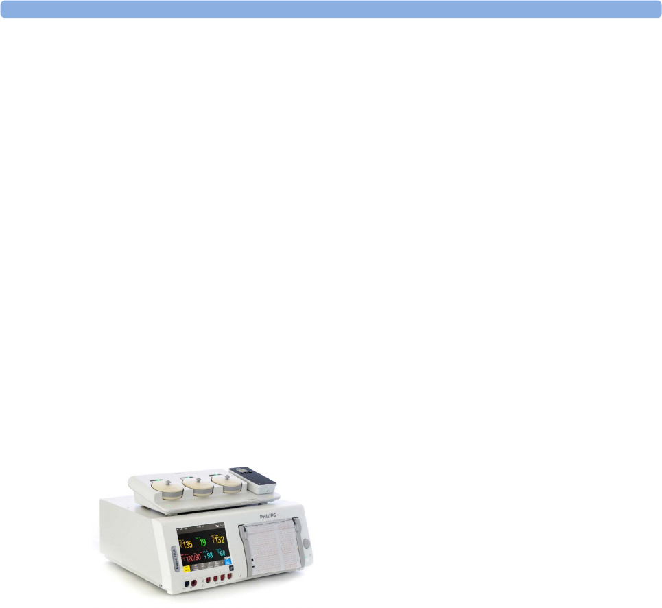
3 IntelliVue CL NBP Pod
66
An assigned Cableless Measurement Device can be removed in the Measurement Selection window. For
more details see the Instructions for Use for your patient monitor.
Assignment with an RFID Reader and Tagged Cableless Devices
You can directly assign all cableless devices that have RFID tags with a Philips HS1-R RFID/barcode
reader. The Respiration Pod has a built-in RFID tag. The NBP Pod used must have an IntelliVue ProxiTag
RFID tag adhesively attached.
1Hold the cableless device close to the reader.
Depending on its configuration, the reader beeps, vibrates or indicates via the LEDs when it has read
the tag.
2Press any hardkey on the cableless device.
The Cableless Measurement Device is now added to the monitor.
If the corresponding internal measurement in the patient monitor is active, you will be asked to confirm that
it should be deactivated in favor of the Cableless Measurement Device by selecting Replace.
If a Cableless Measurement of the same type is already assigned to the monitor, you will be asked to confirm
that it should be removed by selecting Replace.
Assignment at the Fetal Monitor
The first time an IntelliVue Cableless Measurement Device is used with an Avalon Fetal Monitor, or after a
device has been powered off for storage, place it on the Avalon CL Base Station. This will automatically
switch the device on. The device is assigned automatically to the Fetal Monitor working with the CL Base
Station.
NOTE
When you place a Cableless Measurement Device onto an Avalon CL Base Station to assign it to an Avalon
Fetal Monitor, the Cableless Measurement Device is automatically unassigned from the previous patient.
Special Conditions when Working with Fetal Monitors
The following special conditions apply when CL NBP Pods are operating with an Avalon Fetal Monitor as
a host:
• The CL NBP Pods are intended to measure the maternal NBP and Pulse. The patient category is always
Adult.
•The
Pulse measurement is always On. The Pulse: On/Off setting is not available.
• Physiological alarms are only available at the Avalon Fetal Monitor, not at the Cableless Measurement
Devices. Local attended monitoring is not available: Use for Transp. is not supported. (Local attended
monitoring is used for displaying alarms locally at the Cableless Measurement Devices during patient
transport, when the patient is attended by a caregiver).
• Alarm-related operations (e.g. switching alarms on and off, setting the high and low alarm limits) are
not available when Alarm Mode is set to INOP only in the Avalon Fetal Monitor. See the Avalon Fetal
Monitor Instructions for Use and Avalon Fetal Monitor Configuration Guide for further information.

3 IntelliVue CL NBP Pod
67
• You can use the Remove operation at the host to remove Cableless Measurement Devices, as described
in the Avalon Fetal Monitor Instructions for Use.
• STAT mode is not supported.
• Accelerated Measurement mode is not supported.
Assignment with GuardianSoftware
To assign a Cableless Measurement Device to a patient in GuardianSoftware:
1Select the patient on the Chalkboard.
2Take the Cableless Measurement Device from the charger.
3On the Equipment List tab, select the Cableless Measurement Device on the Available Equipment list,
highlighted in green on top of the list. The device on top of the list is always the one with the most
recent user interaction (taken off the charger, put on the charger, or key pressed).
4Click Use for Patient to assign the device to the patient.
Controls Available with a Patient Monitor
The controls available when working with the Cableless Measurement Device and a patient monitor are
described in the table below.
* except when SRR connection to host is lost
WARNING
If a patient being monitored by Cableless Measurement Devices moves out of range of the patient monitor,
the measurements are not transmitted to the patient monitor or the Information Center. The measurements
are available on the Cableless Measurement Device only. If this occurs, the No Host Monitoring message is
displayed on the measurement device. The measurement device will also sound the INOP tone.
Action At the Cableless
Measurement
Device
At the Patient
Monitor
At the IIC
Start/Stop/Stat NBP Yes Yes Yes
Change NBP Mode Yes Yes No
Change NBP Repetition Time Yes Yes No
Change Alarm Limits Yes* Yes No
Assign NBP Pod Yes Yes No
Remove NBP Pod Yes Yes No
Place Device in Standby Yes Yes Yes
Alarm Silence No Yes Yes
Alarm Off/Pause No Yes Yes

3 IntelliVue CL NBP Pod
68
Controls Available with a Telemetry Device
The controls available when working with the Cableless Measurement Device and a TRx4841/TRx4851A
Transceiver or MX40 wearable patient monitor with a short range radio adapter (SRRA) are described in the
table below.
NOTE
When you unplug the ECG cable from the telemetry device and plug it into the monitor associated with the
same patient, the ECG source will automatically be from the monitor. The NBP measurement devices
assigned to the telemetry device will continue to source data to the telemetry device and the Information
Center. You may need to change screens on the patient monitor to see the measurements.
Controls Available with GuardianSoftware
The controls available when working with the Cableless Measurement Device and GuardianSoftware are
described in the table below.
Trending
The IntelliVue Cableless Measurement Devices provide data for trending of parameters. The trended data
are only available via a host system. For details on trends see the Instructions for Use of your host system.
When the connection to the host is lost during measurement, the IntelliVue Cableless Measurement
Devices are able to collect data in a local memory. These data can be uploaded to GuardianSoftware, but
not to other host systems, when a connection is established at a later stage.
Action At the Cableless
Measurement Device
At the IIC
Start/Stop/Stat NBP Yes No
Change NBP Mode Yes No
Change NBP Repetition Time Yes No
Change Alarm Limits No Yes
Assign NBP Pod Yes No
Remove NBP Pod Yes Yes
Place Device in Standby No No
Alarm Silence No Yes
Alarm Off/Pause No Yes
Action At the Cableless
Measurement Device
At GuardianSoftware
Start/Stop/Stat NBP Yes Yes
Change NBP Mode Yes Yes
Change NBP Repetition Time Yes Yes
Assign NBP Pod Yes Yes
Remove NBP Pod Yes Yes
Place Device in Standby No No
Alarm Silence No Yes
Alarm Off/Pause No No

3 IntelliVue CL NBP Pod
69
Monitoring NBP
The IntelliVue CL NBP Pod uses the oscillometric method for measuring NBP. The blood pressure
measurements determined with this device were clinically validated according to ISO 81060-2 in relation to
mean error and standard deviation, when compared to auscultatory measurements (depending on the
configuration) in a representative patient population. The fifth Korotkoff sound was used to determine the
diastolic pressure for adult/adolescent subjects and the 4th for pediatric subjects.
The accuracy of the mean arterial pressure (MAP) was validated using the approximation:
MAPref = (SYSref + 2*DIAref) / 3
with SYSref and DIAref being the blood pressure measured by the auscultatory method.
The NBP measurement is suitable for use in the presence of electrosurgery and during the discharge of a
cardiac defibrillator according to IEC 80601-2-30.
Introducing the Oscillometric NBP Measurement
Oscillometric devices measure the amplitude of pressure changes (oscillations) in the occluding cuff as the
cuff deflates from above systolic pressure. The amplitude suddenly increases as the pulse breaks through the
occlusion in the artery. As the cuff pressure decreases further, the pulsations increase in amplitude, reach a
maximum (which approximates to the mean pressure), and then diminish.
Studies show that, especially in critical cases (arrhythmia, vasoconstriction, hypertension, shock),
oscillometric devices are more accurate and consistent than devices using other noninvasive measuring
techniques.
WARNING
Patient Category: Do not use the IntelliVue CL NBP Pod on neonatal patients. The initial inflation
pressure and overpressure safety limits are too high for neonatal patients and could cause fractures and
bruises.
Intravenous infusion: Do not use the NBP cuff on a limb with an intravenous infusion or arterial catheter
in place. This could cause tissue damage around the catheter when the infusion is slowed or blocked during
cuff inflation.
Skin Damage: Do not measure NBP in cases of sickle-cell disease or any condition where skin damage has
occurred or is expected.
Existing Wounds: Do not apply the cuff over a wound as this can cause further injury.
Mastectomy: Avoid applying the cuff on the side of the mastectomy, as the pressure increases the risk of
lymphedema. For patients with a bilateral mastectomy, use clinical judgement to decide whether the benefit
of the measurement outweighs the risk.
Unattended Measurement: Use clinical judgement to decide whether to perform frequent unattended
blood pressure measurements. Too frequent measurements can cause blood flow interference potentially
resulting in injury to the patient. In cases of severe blood clotting disorders frequent measurements increase
the risk of hematoma in the limb fitted with the cuff.
Temporary Loss of Function: The pressurization of the cuff can temporarily cause loss of function of
monitoring equipment used simultaneously on the same limb.
CAUTION
If you spill liquid onto the equipment or accessories, particularly if there is a chance that it can get inside the
tubing or the measurement device, contact your service personnel.

3 IntelliVue CL NBP Pod
70
Measurement Limitations
NBP readings can be affected by the position of the patient, their physiological condition, the measurement
site, and physical exercise. Thus a physician must determine the clinical significance of the NBP
information.
Measurements are impossible with heart rate extremes of less than 40 bpm or greater than 300 bpm, or if
the patient is on a heart-lung machine.
The measurement may be inaccurate or impossible:
• with excessive and continuous patient movement such as shivering or convulsions
• if a regular arterial pressure pulse is hard to detect with cardiac arrhythmias
• with rapid blood pressure changes
• with severe shock or hypothermia that reduces blood flow to the peripheries
• with obesity, where a thick layer of fat surrounding a limb dampens the oscillations coming from the
artery
• on an edematous extremity.
Accelerated Measurement
When the accelerated measurement is used the minimum number of oscillations per deflation step is 1,
instead of the 2 in the standard measurement. This allows a faster measurement result but requires that the
patient keeps the limb in question still. The accelerated measurement is recommended for use when very
few or no artifacts are expected, for example with sedated patients.
You can see whether the accelerated measurement is in use by looking in the patient monitor's Setup NBP
menu. The Accelerated Msmt setting shows whether the accelerated measurement is Off, on for Manual
measurements or on for All measurements. You can see this setting in Monitoring Mode but it can only be
changed in Configuration Mode.
When the accelerated measurement is in use, no pulse rate is derived from NBP.
Measurement Modes
There are three modes for measuring NBP:
•Manual - measurement on demand.
•Auto - continually repeated measurements (between one minute and 24 hours adjustable interval).
•Sequence - up to four measurement cycles which will run consecutively, with number of measurements
and interval between them configurable for each cycle.
Auto and Sequence modes must be set up, before a measurement series can be started. See “Enabling
Automatic Mode and Setting Repetition Time” on page 74 and “Enabling Sequence Mode and Setting Up
The Sequence” on page 75.
Additionally, you have the possibility to start an immediate, one-time measurement series at any time:
•STAT - rapid series of measurements over a five minute period. Use only on supervised patients.
After a STAT measurement series, the monitor returns to the previous mode. If an Auto or Sequence
measurement series was running before the STAT measurement, it will continue to run afterwards.
Reference Method
The measurement reference method is always Auscultatory (manual cuff). For further information, see the
Application Note supplied on the documentation DVD.
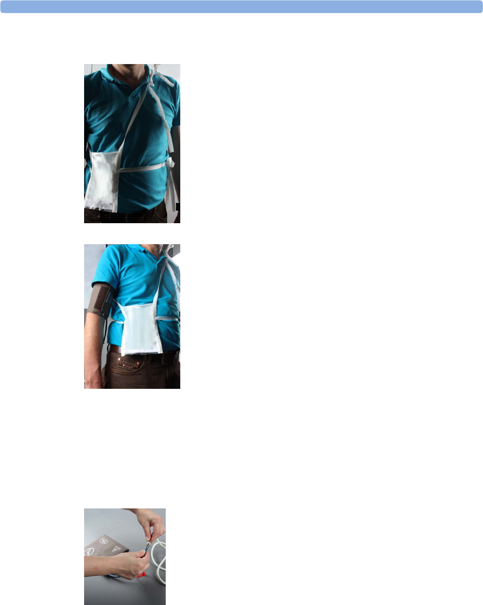
3 IntelliVue CL NBP Pod
71
Preparing to Measure NBP with Standard Cuffs
1Apply the carrying pouch to the patient.
2Apply the cuff to the patient's upper arm at the same level as the heart.
If the cuff is not at heart level, you must use the measurement correction formula to correct the
measurement.
Make sure that you are using a Philips-approved correct sized cuff and that the bladder inside the cover
is not folded or twisted.
A wrong cuff size, and a folded or twisted bladder, can cause inaccurate measurements. The width of
the cuff should be in the range from 37% to 47% of the limb circumference.
Do not wrap the cuff too tightly around the limb. It may cause discoloration, and ischemia of the
extremities.
3Connect the extension air hose to the cuff.
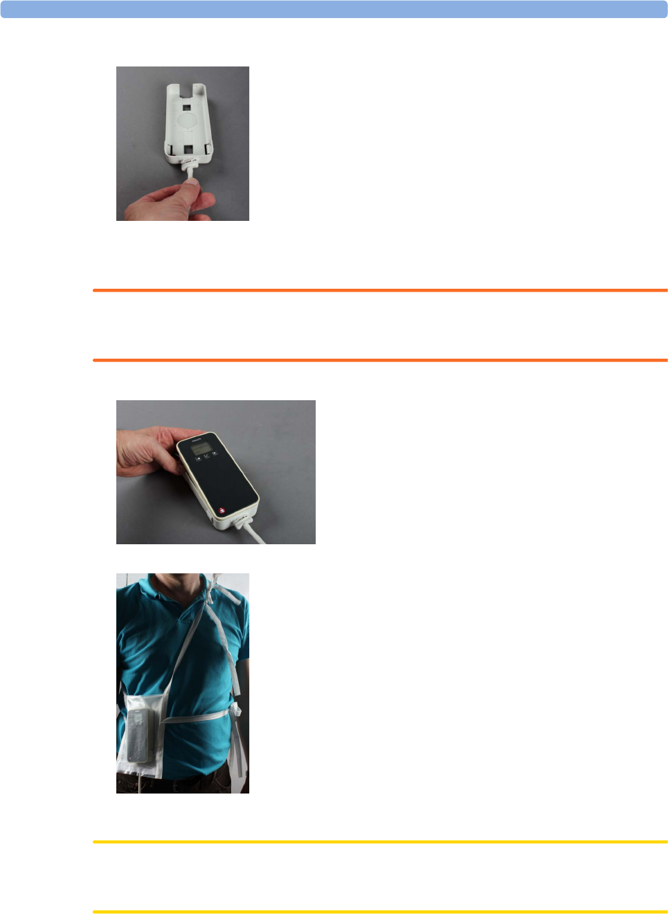
3 IntelliVue CL NBP Pod
72
4Connect the extension air hose to the cradle.
Hold the flat part of the connector vertically when plugging it into the inlet, then twist it clockwise to
lock into place. Avoid compression or restriction of pressure tubes. Air must pass unrestrictedly
through the tubing.
WARNING
Kinked or otherwise restricted tubing can lead to a continuous cuff pressure, causing blood flow
interference and potentially resulting in injury to the patient.
5Place the NBP Pod into the cradle.
6Put the NBP Pod into the carrying pouch.
Make sure to pinch the velcro enclosures firmly together around the extension hose exiting from the
pouch.
CAUTION
Make sure that the air vent, located next to the air tubing connector on the NBP Pod, is not covered
during operation. If air cannot enter the air vent, the pump may be damaged.

3 IntelliVue CL NBP Pod
73
WARNING
Inspect the application site of the cuff regularly to ensure skin quality and inspect the extremity of the
cuffed limb for normal color, warmth and sensitivity. If the skin quality changes, or if the extremity
circulation is being affected, move the cuff to another site or stop the blood pressure measurements
immediately. Check more frequently when making automatic or stat measurements.
Attaching the Pod Directly to a Mobile CL Cuff
As an alternative to using a carrying pouch, you can attach the NBP Pod directly to the cuff. In this case you
do not need the extension hose.
1Attach the cradle to the NBP cuff.
2Plug the air tubing into the cradle.
3Apply the cuff to the patient's upper arm.
Apply the cuff so that the cradle is located at the outside of the arm. The bladder of the cuff is then
automatically over the artery.
4Insert the NBP Pod into the cradle.
Additional Information
The following documents contain additional information, depending on which accessories you are using:
• Mobile CL Reusable NBP Cuffs Instructions for Use
• Mobile CL Single-Patient NBP Cuffs Instructions for Use
• Mobile CL NBP Cradle Instructions for Use
• Mobile CL Extension Air Hose Instructions for Use
Recommendations For Measurements Used in Diagnosis of Hypertension
To make a measurement for use in the diagnosis of hypertension, follow the steps below:
1Ensure the patient is comfortably seated, with their legs uncrossed, feet flat on the floor and back and
arm supported.
2Ask the patient to relax and not talk before and during the measurement.
3If possible, wait 5 minutes before making the first measurement.
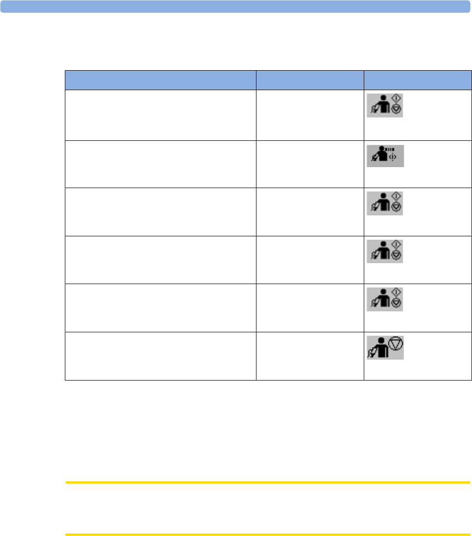
3 IntelliVue CL NBP Pod
74
Starting and Stopping Measurements
Use the setup menu or SmartKeys to start and stop measurements.
Depending on the configuration of the NBP Auto/Sequence series, measurements are automatically started
within 3 seconds (Automatic Start set to Fast) or 3 minutes (Automatic Start set to Slow) after the NBP Pod
has been inserted into the cradle. With Automatic Start set to Off, the Auto/Sequence series have to be
started manually.
No pulse can be derived from the NBP measurement in Accelerated and STAT mode.
If accelerated measurement mode is configured for manual or manual and Auto/Sequence measurements,
make sure that the patient is not moving during the measurements.
CAUTION
Use clinical judgment to decide whether to perform repeated series of STAT measurements because of the
risk of purpura, ischemia and neuropathy in the limb with the cuff.
Enabling Automatic Mode and Setting Repetition Time
1In the NBP menu, select Mode and select Auto from the pop-up menu.
2For an automatic measurement, select Repeat and set the time interval between two measurements.
Action to be Performed NBP Setup menu SmartKeys
Start manual measurement
Start Auto series
Start measurement sequence
Start/Stop
Start/Stop
Start STAT measurement Start NBP Stat
Start NBP STAT
Stop Manual measurements Start/Stop
Start/Stop
Stop current Auto/sequence measurement Start/Stop
Start/Stop
Stop current STAT measurement and end
STAT mode
Start/Stop
Start/Stop
Stop Auto, Manual or STAT measurement,
end STAT mode AND Auto/Sequence series
Stop All
Stop All
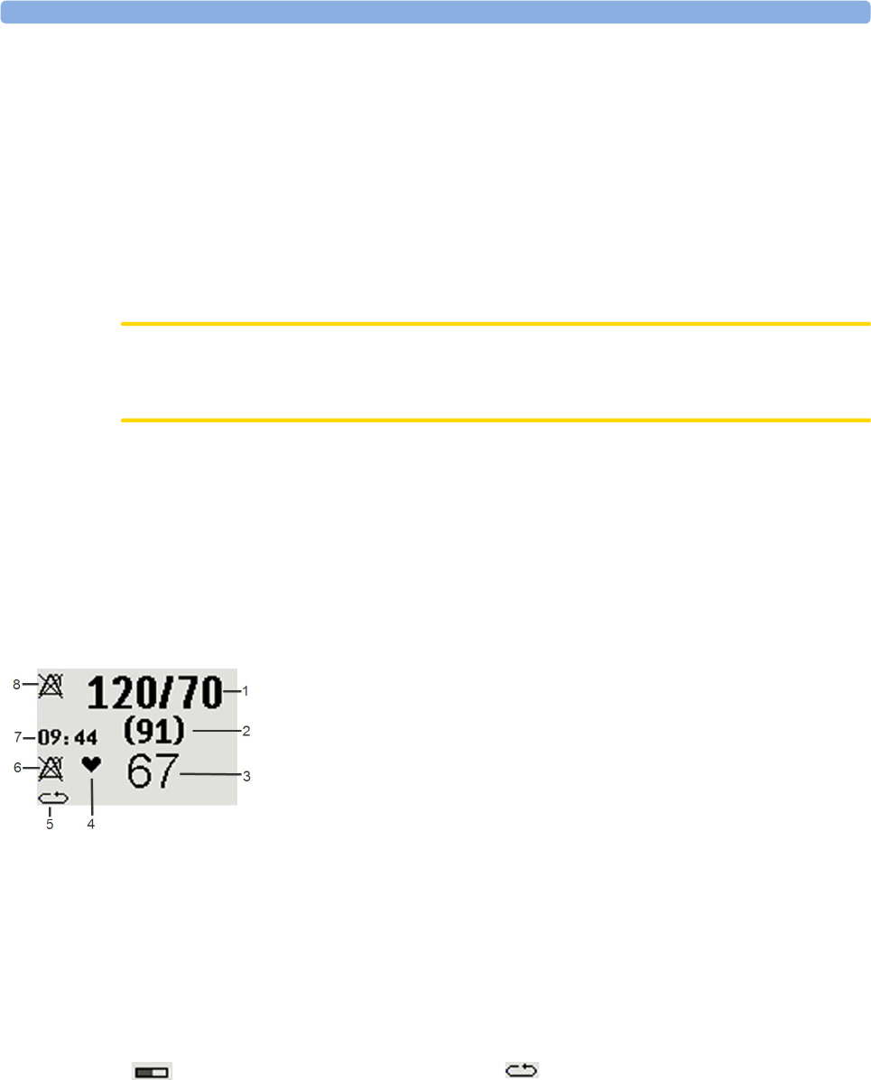
3 IntelliVue CL NBP Pod
75
Enabling Sequence Mode and Setting Up The Sequence
1In the NBP menu, select Mode and select Sequence from the pop-up menu.
2Select Setup Sequence to open the Setup Sequence menu.
Up to four measurement phases can be setup which will run consecutively. For each phase you can set
the number of measurements and the interval between them. If you want to run less than four phases in
a sequence, you can set the number of measurements for one or more phases to Off.
3Select each phase in turn (A, B, C and D) and select the number of measurements and the time interval
between the measurements.
4To have measurements continue after the sequence, set the number of measurements for your last
phase to Cont and this phase will run indefinitely.
CAUTION
Be aware that, if none of the phases are set to Cont, NBP monitoring will end after the last measurement of
the last phase.
When the NBP measurement mode is set to Sequence, the repetition time for Auto mode cannot be
changed.
Announcement Tone:
Depending on the configuration of the NBP Pod, a tone before each measurement announces the next
measurement. Please inform the patient to stop moving, and especially stop moving the arm with the cuff,
when the tone sounds and the cuff inflates in order to allow a fast and accurate measurement.
Understanding the NBP Numerics and Symbols
Note: The Alarms Off symbols indicate that no physiological alarms are available from the Cableless
Measurement Devices when not assigned to a host.
Measurement modes with a series of measurements can be indicated with two different symbols:
An S in front of the symbol indicates Sequence mode and an A, B, C or D indicates which phase of the
sequence is currently running.
1Systolic/Diastolic pressure
2Mean pressure
3Pulse rate
4Pulse rate indicator
5Measurement mode (see below)
6Alarms Off symbol for Pulse (Pulse from NBP does not
have alarm capability, therefore it cannot be switched
on)
7Timestamp
8Alarms Off symbol for NBP
indicates that a series is running and
shows the relative time to the next
measurement.
indicates that auto or sequence mode is
selected but the measurement series has not
yet started.

3 IntelliVue CL NBP Pod
76
During Measurements
The cuff pressure is displayed instead of the timestamp.
Correcting the Measurement if Limb is not at Heart Level
To correct the measurement if the limb is not at heart level, to the displayed value
When Unexpected Values are Measured
When values measured are higher or lower than expected, check the following potential causes:
Switching Pulse from NBP On/Off
In the process of making the NBP measurement, a pulse value can be derived and displayed. The pulse
value is displayed together with the time the measurement was made. After one hour the value becomes
invalid. There are no alarms associated with pulse from NBP.
When the accelerated measurement is in use, no pulse value can be derived.
To switch the display of the pulse value on or off:
•In the NBP menu select Pulse.
Assisting Venous Puncture
You can use the NBP cuff to cause subdiastolic pressure. The cuff deflates automatically after a set time
(adult/pediatric 170 seconds) if you do not deflate it.
1In the NBP menu select Veni Puncture, or select the Veni Puncture SmartKey.
2Puncture vein and draw blood sample.
3Reselect Veni Puncture to deflate the cuff.
During measurement, the NBP display shows the inflation pressure of the cuff and the remaining time in
venous puncture mode.
Calibrating NBP
NBP is not user-calibrated. NBP pressure transducers must be verified and calibrated, if necessary, at least
once every two years by a qualified service professional. See the Service Guide for details.
Add 0.75 mmHg (0.10 kPa) for each centimeter
higher or
Deduct 0.75 mmHg (0.10 kPa) for each
centimeter lower or
Add 1.9 mmHg (0.25 kPa) for each inch higher. Deduct 1.9 mmHg (0.25 kPa) for each inch lower.
Possible Cause Solution
The patient was talking or moving before or during
the measurement.
Allow the patient to rest quietly, then try again after
three to five minutes.
The incorrect cuff size was used or the cuff was not
at heart level
Check the cuff size, level, and position then repeat
the measurement.
Measurement limitations have not been taken into
account.
Check the list in “Measurement Limitations” on
page 70.

3 IntelliVue CL NBP Pod
77
Alarms
The IntelliVue Cableless Measurements have two different types of alarm: patient alarms and technical
alarms (INOPs).
Patient Alarms
Patient Alarms are high priority alarms (such as a potentially life threatening situation), also called red
alarms, or medium priority alarms, also called yellow alarms.
Technical Alarms (INOPs)
Technical alarms, also known as INOPs, indicate that the measuring device cannot measure reliably. If an
INOP interrupts monitoring, there will be a question mark in place of the measurement numeric. An INOP
tone sounds at the Cableless Measurement Device only when there is no SRR connection to a host.
Exception: the Battery empty INOP tone sounds also with SRR connection.
Most INOPs are low priority, however there are a small number of INOPs which, due to their severity, are
medium or high priority.
Alarm Delays
There is a delay between a physiological event at the measurement site and the corresponding alarm
indication at the Cableless Measurement Device. This delay has two components:
• The general measurement delay time is the time between the occurrence of the physiological event and
when this event is represented by the displayed numerical values. This delay depends on the algorithmic
processing.
• The time between the displayed numerical values crossing an alarm limit and the alarm indication on
the device is the system alarm delay. The system alarm delay is the processing time the system needs for
any alarm on the Cableless Measurement Device to be indicated after the measurement has triggered
the alarm. This delay depends on the Cableless Measurement Device and the connected host system.
See the performance specifications in the chapter “IntelliVue CL NBP Pod Specifications” on page 135
for the system alarm delay specification of the Cableless Measurement Device.
The alarm delay configured for a specific measurement is normally a fixed time.
Multiple Alarms
If more than one alarm is active, the alarm messages are shown in the alarm status area in succession. An
arrow symbol next to the alarm message informs you that more than one message is active.
The Cableless Measurement Device sounds an audible indicator for the highest priority alarm. If more than
one alarm condition is active in the same measurement, the Cableless Measurement Device announces the
most severe.
NOTE
If you want to use local attended monitoring, make sure to have all Cableless Measurement Devices
upgraded to at least Rev. B.02.
Visual Alarm Indicators
WARNING
• No patient alarms are available on the Cableless Measurement Devices when assigned to a host monitor
(unless they are selected for use in patient transport at the monitor they are assigned to) or
GuardianSoftware.
• Visual patient alarm indicators are disabled on the Cableless Measurement Devices when connected to
a host monitor (unless they are selected for use in patient transport at the monitor they are assigned to)
or GuardianSoftware.

3 IntelliVue CL NBP Pod
78
Alarm Message
Alarm messages are displayed in black on a light gray background in the alarm status area at the top of the
screen indicating the source of the alarm and coded according to their severity. If more than one
measurement is in an alarm condition, the message changes every few seconds, and has an arrow ( ) at the
side. The asterisk symbols (*) beside the alarm message match the alarm priority: *** for red alarms, ** for
yellow alarms. Standard INOPs do not have a symbol, red and yellow INOPs have exclamation marks
beside the alarm message: !!! for red INOPs and !! for yellow INOPs.
An alarm message that appears is automatically highlighted. Use the key to silence the message. A Silence
message is displayed at the bottom of the screen and highlighted. Press again to confirm the
acknowledgment of the alarm. After the confirmation, any ongoing alarm message is displayed in the icon
tray of the screen.
Alarm States
Depending on the alarm state of your Cableless Measurement Device, the following icons may be displayed
on the device:
Audible Alarm Indicators
Audible alarm indicator patterns are repeated until you acknowledge the alarm by switching it off or pausing
it, or until the alarm condition ceases (if audible alarm indication is set to non-latching).
Cableless Measurements Devices alone (without host, e.g. a patient monitor) are not suitable for unattended
monitoring due to their limited alarm volume.
WARNING
• Do not rely exclusively on the audible alarm system for patient monitoring. Adjustment of alarm
volume to a low level or off during patient monitoring may result in patient danger. Remember that the
most reliable method of patient monitoring combines close personal surveillance with correct
operation of monitoring equipment.
• No patient alarms are available on the Cableless Measurement Devices when connected to a host
monitor (unless they are selected for use in patient transport at the monitor they are assigned to) or to
GuardianSoftware.
• When connected to a host monitor or GuardianSoftware, no alarm tones are available on the Cableless
Measurement Devices (unless they are selected for use in patient transport at the monitor they are
assigned to).
Icon Description
No local alarming on Cableless Measurement Device. The device is connected
to a host monitor or telemetry device and has no visual or audible patient alarm
indicators. The device will only display INOP messages.
Alarms are switched off.
Alarm volume is set to 0.

3 IntelliVue CL NBP Pod
79
Silencing an Alarm
To silence an alarm, press the key.
This will silence the alarm tone and clear the alarm message. If the condition which caused the alarm is still
present, the alarm indicator will be displayed on the right hand side of the screen.
When using a Cableless Measurement Pod with an IntelliVue Information Center iX Release A, make sure
to remove the pod at the telemetry device and only when in SRR range of the telemetry device. Otherwise
you will get a technical alarm (cl NBP Disconnect) that can not be silenced at the telemetry device. You will
then have to reboot the telemetry device to remove the message.
Displaying a List of Current Alarms
To display a list of the currently active alarms,
1Select the Alarms SmartKey or Main Setup SmartKey, followed by Alarms.
2Select Alarm Messages.
Setting the Volume of the Alarm Tone
To set the volume for the Alarm tone,
1Select the Alarms SmartKey or Main Setup SmartKey, followed by Alarms.
2Select AlarmVol and select a volume setting. The maximum is 10 and the minimum depends on your
configuration.
If the volume of the Alarm tone is set to zero, the following symbol is displayed on the right icon tray of the
Cableless Measurement Device screen:
Minimum Volume for No Host Monitoring INOP
If your device is connected to a host monitor, and the connection is interrupted, the INOP message No
Host Monitoring will appear within 30 seconds, accompanied by an INOP tone. To help ensure that this
INOP, and any other active alarm, is not overlooked, the INOP and alarm tones may be configured to have
a minimum volume. In this case, INOP and alarm tones will sound even if the device alarm volume is set to
zero.
Alarm Reminder
If Reminder is configured on your device, you will get an audible reminder of alarm conditions that remain
active after you have silenced the alarm. This reminder may take the form of a repetition of the alarm tone
for a limited time, or an unlimited repetition of the alarm tone (this is the same as a new alarm). Alarm
Reminder is not available for standard, light blue INOPs but for yellow and red INOPs.
In Configuration Mode, you can set the interval between silencing the alarm and sounding the reminder
tone to one, two, or three minutes.
1Full length alarm message
2Alarm indicator
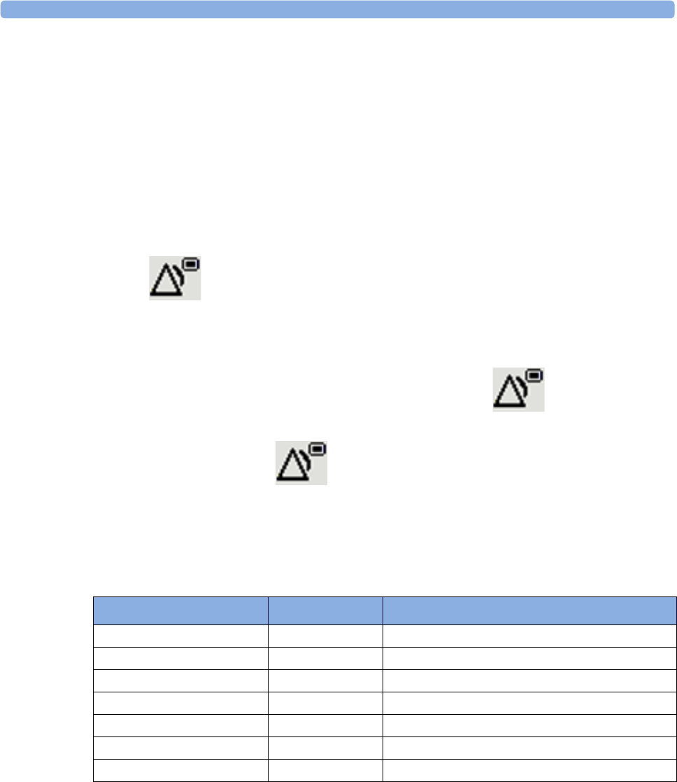
3 IntelliVue CL NBP Pod
80
Pausing or Switching Off Alarms
If you want to temporarily prevent alarms from sounding, for example while you are moving a patient, you
can pause alarms. Depending on your device configuration, alarms are paused for one, two, or three
minutes, or infinitely. Infinite alarm pause is equivalent to switching the alarms off.
To view the alarm pause setting chosen for your unit,
1In the SmartKeys Menu select Main Setup, Alarms, then OffDurat.
2Check the setting.
This setting can only be changed in Configuration Mode.
To Pause or Switch Off Alarms
Select the key in the SmartKeys Menu followed by Alarms. Press the hardkey to switch to
Paused. If your device is configured to infinite pause time, selecting this option switches alarms off.
Restarting Paused Alarms
To manually switch on alarm indication again after a pause, select the key again.
Alarm indication starts again automatically after the pause period expires. If the device is configured to stay
paused infinitely, you must select again to restart alarm indication.
Choosing the NBP Alarm Source
You can monitor for alarm conditions in systolic, diastolic and mean pressure, either singly or in parallel.
Only one alarm is given, with the priority of mean, systolic, diastolic.
In the NBP menu, select Al. from and choose from:
If Mean is not selected as alarm source (Sys., Dia., or Sys & Dia selected), but the monitor can only derive a
mean value, mean alarms will nevertheless be announced using the most recent mean alarm limits. Check
that the mean alarm limits are appropriate for the patient, even when not using mean as the alarm source.
When no value can be derived an NBP Measure Failed INOP will be displayed.
Menu Option Displayed as Pressure value monitored
Sys. Sys. systolic
Dia. Dia. diastolic
Mean Mean mean
Sys & Dia S & D systolic and diastolic in parallel
Dia & Mean D & M diastolic and mean in parallel
Sys & Mean S & M systolic and mean in parallel
Sys&Dia&Mean S&D&M all three pressures in parallel

3 IntelliVue CL NBP Pod
81
Alarm Limits
The alarm limits you set determine the conditions that trigger limit alarms.
WARNING
Be aware that the devices in your care area may each have different alarm settings, to suit different patients.
Always check that the alarm settings are appropriate for your patient before you start monitoring.
Adjusting the Alarm Limits
1Select the Alarms SmartKey followed by Alarm Limits (or select Main Setup followed by NBP).
2Depending on your alarm source:
a. Select Sys.High, Dia.High and/or MeanHigh then choose the high alarm limit.
b. Select Sys. Low, Dia. Low and/or Mean Low then choose the low alarm limit.
Latching Alarms
The alarm latching setting for your device defines how the alarm indicators behave when you do not
acknowledge them. When alarms are set to non-latching, their indicators end when the alarm condition
ends. Switching alarm latching on means that visual and/or audible alarm indications are still displayed or
announced by the device after the alarm condition ends. The indication lasts until you acknowledge the
alarm.
Viewing the Alarm Latching Settings
To see the alarm latching setting for your device,
1In the Main Setup menu, select Alarms.
2Here you can see the Visual Latching and Audible Latching settings.
This setting can only be changed in Configuration Mode. You should be aware of the settings chosen for
your unit. There are three possible choices each for visual and audible latching, red only, red and yellow, and
off. These choices can be combined to give the following settings:
Alarm Latching Behavior
As NBP is an aperiodic parameter, "Alarm condition no longer present" means either that for a
measurement in alarm the alarm limits are changed in such a way that the value is now within the limits, or
that a new measurement is done with a value within the limits.
Visual Latching Audible Latching
Red&Yellow Red&Yellow
Red&Yellow Red Only
Red&Yellow Off
Red Only Red Only
Red Only Off
Off Off

3 IntelliVue CL NBP Pod
82
All INOPs are non-latching. NBP specific INOPs generated by the CL Pod are latching.
Testing Alarms
When you switch the CL NBP Pod on, a selftest is started. You must check that the backlight switches on,
and that you hear a single tone. This indicates that the alarm indicators are functioning correctly. For further
testing of individual measurement alarms, perform the measurement on yourself or use a simulator. Adjust
alarm limits and check that appropriate alarm behavior is observed.
Alarm Behavior at Power On
If the device is switched off (Standby), all alarm settings are maintained. If the device is switched off
completely (Power Off), or the battery is completely empty, resulting in complete power loss, all alarm
settings will be lost unless they were actively saved by storing the active profile before the device was
switched off. See “Switching the Device Off” on page 17 and “Using Profiles” on page 18 for details.
When the device is switched back on from either state, it will start in Profile A and you may have to switch
to the desired profile which contains your alarm settings.
After any of these situations, you should check that the alarm settings are appropriate for your patient and
monitoring situation, and if necessary, select the correct Profile and patient category.
Reference List of Patient Alarms
Reference List of all INOPs
Red & Yellow Measurement
Alarms
Non-latching alarms Visual and audible latching Visual latching, audible
non-latching
Alarm has not
been
acknowledged.
Alarm condition
still present.
Alarm tone on. Alarm message. Alarm tone on. Alarm
message.
Alarm tone on. Alarm
message.
Alarm condition
no longer present.
All audible and visual alarm
indicators automatically stop.
Alarm tone on.
Alarm message.
Alarm message.
Audible alarm indicators
automatically stop.
Alarm has been
acknowledged.
Alarm condition
still present.
All audible and visual alarm
indicators automatically stop.
All audible and visual alarm
indicators automatically stop.
All audible and visual alarm
indicators automatically stop.
Alarm condition
no longer present.
Audible and visual alarm
indicators automatically stop.
Audible and visual alarm
indicators automatically stop.
Audible and visual alarm
indicators automatically stop.
Alarm Message, Indication Source Condition
** NBPs High
** NBPd High
** NBPm High
NBP The measured NBP value is above the high alarm limit.
s, d, or m after the label indicates whether the systolic,
diastolic or mean pressure has crossed the limit.
** NBPs Low
** NBPd Low
** NBPm Low
NBP The measured NBP value is below the low alarm limit.
s, d, or m after the label indicates whether the systolic,
diastolic or mean pressure has crossed the limit.

3 IntelliVue CL NBP Pod
83
INOP Message, Indication Source What to do
Batt Incompatible
INOP tone
Battery Battery cannot be used with this Cableless Measurement
Device. Replace battery with one that has been approved for
use with this Cableless Measurement Device. Contact your
service personnel.
Batt Malfunction
INOP tone
Battery Malfunction of the battery system detected (charger circuit
or battery). Contact your service personnel.
Battery Empty
INOP tone
Battery The remaining monitoring time is below 30 minutes. Charge
battery.
Battery Low
INOP tone
Battery The remaining monitoring time is below 2 hours.
Check Batt Temp
INOP tone
Battery The temperature of the battery is critically high. Check that
Cableless Measurement Device is not covered and not
exposed to a heat source. If INOP persists, remove
Cableless Measurement Device from patient and contact
your service personnel.
Check Battery
INOP tone
Battery The maximum number of charge/discharge cycles of the
battery will be reached in less than 50 cycles. Contact your
service personnel to replace the battery.
Check Charger I/F
INOP tone
Battery Overvoltage or undervoltage detected at the charger
interface. Clean contacts of charger interface at Cableless
Measurement Device and charging station. If the INOP
persists, contact your service personnel.
cl NBP ChkSettings
INOP tone
Cableless Measurement
Device
If this INOP appears and an INOP tone sounds, check the
Cableless Measurement Device and patient settings before
you resume making measurements. If the settings are
unexpected, there may be a problem with the Cableless
Measurement Device software. Contact your service
personnel.
If this INOP is acknowledged at the Cableless Measurement
Device, it is cleared. If it is silenced remotely, only the tone
is cleared.
cl NBP Disconnect
only at the host
Cableless Measurement
Device
The NBP Pod has lost the SRR connection to the telemetry
device or the patient monitor.
Cuff Not Deflated
Numeric is replaced by -?-
INOP tone
During this INOP, alarms cannot be
paused or switched off.
NBP The NBP cuff pressure has exceeded 15 mmHg (2 kPa) for
more than 3 minutes.
Remove the cuff from the patient. Make sure that the tubing
is not kinked or twisted and that the correct patient category
is selected. Try repeating the measurement. You can
acknowledge the INOP, but the INOP message remains
visible until the next NBP measurement is started or the
Stop All SmartKey is selected.

3 IntelliVue CL NBP Pod
84
NBP Check Cuff
Numeric is replaced by -?-
INOP tone
NBP Check if cuff is connected to the NBP Pod and cuff is
applied to the patient; check tubing and cuff for leakage.
Try restarting the measurement. If the INOP occurs
repeatedly, contact your service personnel. You can silence
this INOP, but the INOP message remains visible until the
next measurement is started or the Stop All SmartKey is
selected.
This INOP arises when the maximum time for inflation is
exceeded or when there is a significant change in inflation
time between two successive measurements in auto and
sequence mode.
NBP Cuff Overpress
Numeric is replaced by -?-
INOP tone
During this INOP, alarms cannot be
paused or switched off.
NBP The NBP cuff pressure exceeds the overpressure safety
limits. Remove the cuff from the patient. Make sure that the
tubing is not kinked or twisted and that the correct patient
category is selected. Try restarting the measurement. You
can acknowledge this INOP, but the INOP message
remains visible until the next measurement is started or the
Stop All SmartKey is selected.
NBP Equip Malf
Numeric is replaced by -?-
INOP tone
NBP Remove the NBP Pod and cuff from the patient. The NBP
hardware is faulty. Contact your service personnel. You can
acknowledge this INOP, but the INOP message remains
visible until the next measurement is started or the Stop All
SmartKey is selected.
NBP Interrupted
Numeric is replaced by -?-
INOP tone
NBP Check the tubing and cuff for leakages or kinks. Check that
you are using the correct cuff size and placement, and that
the correct patient category is selected. Try restarting the
measurement. If the INOP occurs repeatedly, contact your
service personnel. You can silence this INOP, but the INOP
message remains visible until the next measurement is
started or the Stop All SmartKey is selected. This INOP
arises when the measurement needed longer than the
maximum time for deflation or the total measurement.
NBP Measure Failed
Numeric is replaced by -?-
INOP tone
NBP Check that you are using the correct cuff size and
placement, and that the correct patient category is selected.
Try restarting the measurement. You can silence this INOP,
but the INOP message remains visible until the next
measurement is started or the Stop All SmartKey is selected.
Check the condition and suitability of the patient for NBP
monitoring. Use another cuff to continue measuring.
NBP Neo Patient?
Numeric is replaced by -?-
INOP tone
NBP The patient monitor that the NBP pod is assigned to is in
neonatal mode or a neonatal cuff has been detected. The
monitor must be in adult or pediatric mode.
No Cradle
Numeric is replaced by -?-
INOP tone
NBP The NBP Pod is not in the cradle. You can silence this
INOP, but the INOP message remains visible until the NBP
Pod is inserted into the cradle and the next measurement is
started or the Stop All SmartKey is selected.
If INOP appears with the NBP Pod inserted into the cradle,
remove and replace the cradle.
INOP Message, Indication Source What to do

3 IntelliVue CL NBP Pod
85
No Host Monitoring
INOP tone
Cableless Measurement
Device
There is a problem with the communication to the assigned
patient monitor and monitoring is currently not possible (no
patient alarms or information). Check the connection.
Contact your service personnel.
No System Cableless Measurement
Device
There is a problem with the communication to the network
and central monitoring is currently not possible. Check the
connection.
Remove From Pat
INOP tone
Cableless Measurement
Device
Displayed on the Cableless Measurement Device. The
temperature of the battery is too high. Remove the Cableless
Measurement Device from the patient and contact service
personnel.
Service Battery
INOP tone
Battery Maximum number of charge/discharge cycles for battery
exceeded. Charging of the battery is inhibited. Contact your
service personnel to replace battery.
INOP Message, Indication Source What to do
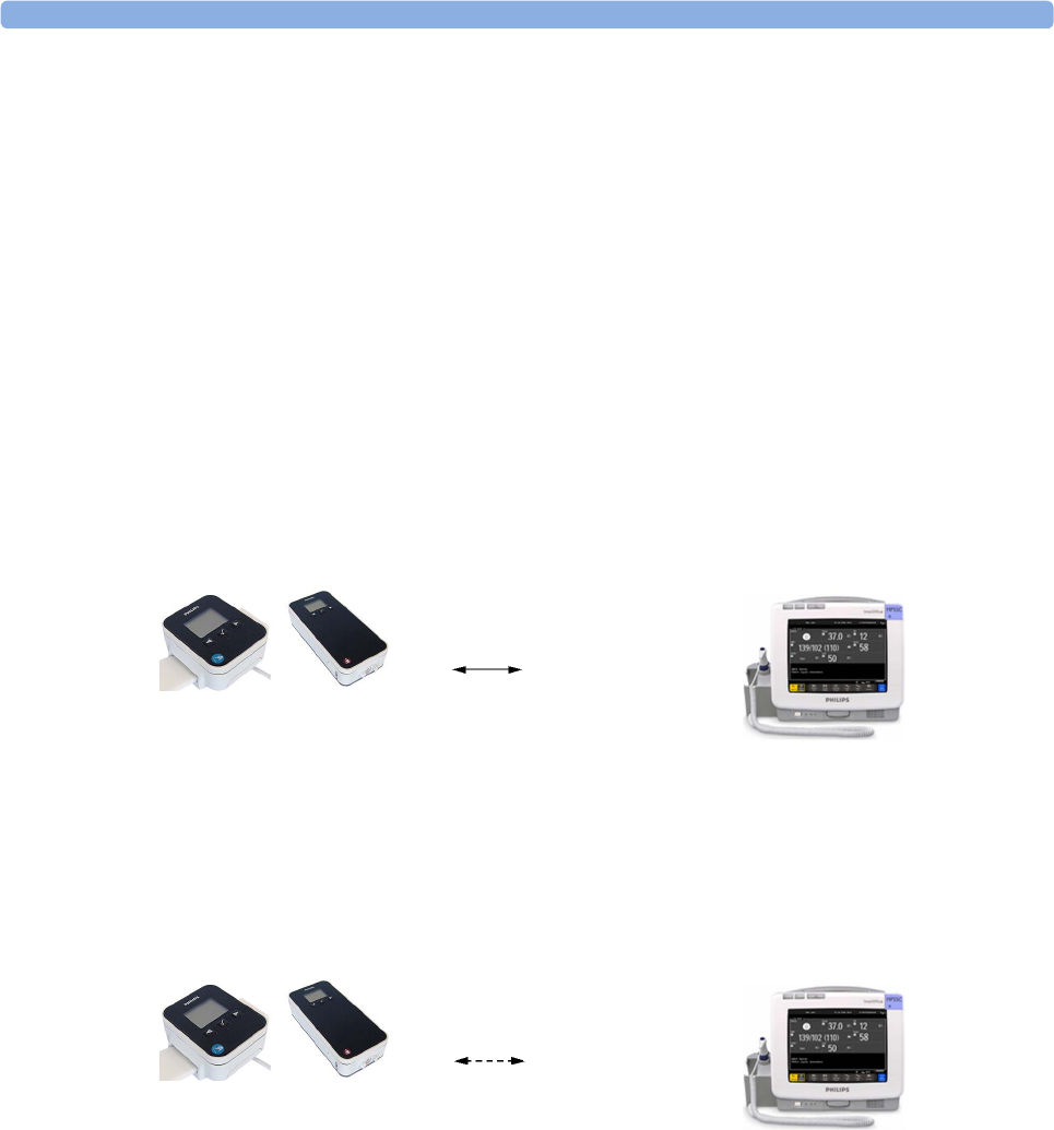
3 IntelliVue CL NBP Pod
86
Local Attended Monitoring
When working with an IntelliVue MP5, MP5SC, MP5T Patient Monitor with software revision J.2 or higher
as a host, or with an IntelliVue X2 Multi-Measurement Module with software revision K.2 or higher, the
IntelliVue CL SpO2 and NBP Pods can be used for local attended monitoring. This is for situations where
you want to have alarm indications at the CL Pods when they are out of reach of the patient monitor
(disconnected). The patient monitor setting to switch CL Measurement Alarms on and off (cl Alarms On/
Off) is used to enable and disable this functionality. As a default, the CL Measurement Alarms are on.
Local Attended Monitoring Enabled
By default, the patient monitor is set to receive alarms from the CL Pods (can only be changed in
configuration mode). This scenario is used for patients who require uninterrupted monitoring. The various
alarms from the CL Pods are indicated at the patient monitor if they are enabled at the monitor. When the
CL Pod is disconnected from the patient monitor and the caregiver has activated the transport mode at the
monitor, physiological alarms are indicated locally at the CL Pod. A cl NBP Disconnect INOP is shown at
the monitor if the SRR connection is lost and the transport mode has not been activated.
CL Pod connected to a patient monitor and CL Measurement Alarms On (Standard Use Model):
CL Pod disconnected from patient monitor and CL Measurement Alarms On, Local Attended
Monitoring:
SRR connection
At the CL Pod:
Indication of technical
alarms only
At the monitor:
Indication of physiological and
technical alarms from CL Pods
No SRR connection
At the CL Pod:
Indication of technical and
physiological alarms
At the monitor:
No indication of physiological
alarms from CL Pods. No
indication of technical alarms
after disconnection.

3 IntelliVue CL NBP Pod
87
Local Attended Monitoring Disabled
The patient monitor is set to cl Alarms Off (this can only be done in configuration mode). This scenario is
used if the patients do not require permanent monitoring and are mobile, but vital signs are taken from time
to time. All alarms from the CL Pods are switched off at the monitor. If the SRR connection is lost, no cl
NBP Disconnect INOP is shown at the monitor in this scenario.
CL Pod connected to a patient monitor and CL Measurement Alarms Off:
CL Pod disconnected from patient monitor and CL Measurement Alarms Off:
SRR connection
At the CL Pod:
Indication of technical
alarms only
At the monitor:
No indication of physiological
alarms from CL Pods.
Indication of technical alarms
from CL Pods.
No SRR connection
At the CL Pod:
Indication of technical
alarms only
At the monitor:
No indication of physiological
and technical alarms from CL
Pods.
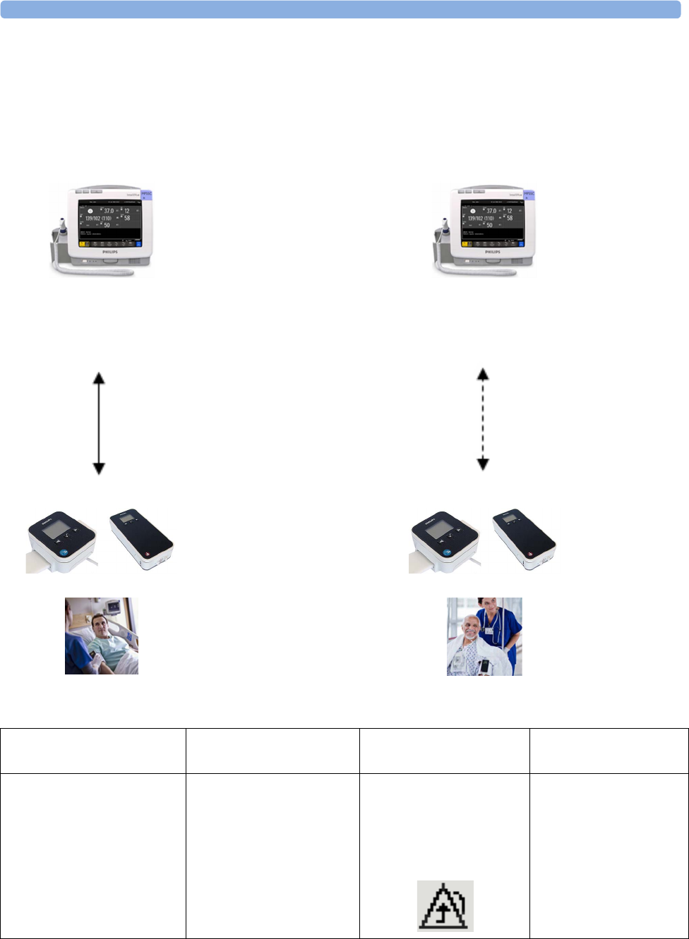
3 IntelliVue CL NBP Pod
88
Alarm Availability: Standard Use Model versus Local Attended Monitoring with CL
Measurement Alarms On
12
Standard Use Model Local Attended Monitoring
->
Caregiver activates
'Use for transport'
<-
Caregiver activates
'Use with monitor'
SRR connection no SRR connection
Action / Event Situation Alarm Availability
at CL Pod
Alarm Availability
at Patient Monitor
Standard Use Model:
normal operation,
no special action
CL Pod connected to the
patient monitor (1)
Technical alarms
(own)
No physiological alarms
No Local Alarming icon is
displayed:
Technical alarms
(own + from Pod)
Physiological alarms
(own + from Pod)

3 IntelliVue CL NBP Pod
89
Activation of Local Attended
Monitoring:
Caregiver activates Local
Attended Monitoring and
disconnects CL Pod temporarily
by setting Use for Transp. in the
Patient Monitor's Equipment
window
Patient is in transport without
connection to the host system,
caregiver attends the patient
(2)
Technical alarms
(own)
Physiological alarms
(own)
Technical alarms
(own)
Physiological alarms
(own)
No alarms from CL Pod
Deactivation of Local
Attended Monitoring:
Caregiver deactivates Local
Attended Monitoring and
reconnects CL Pod to a patient
monitor by setting Use with
Monitor in the patient monitor's
Equipment window
Patient returns from
transport.
Back to the standard use
model (1)
Technical alarms
(own)
No physiological alarms
No Local Alarming icon is
displayed:
Technical alarms
(own + from Pod)
Physiological alarms
(own + from Pod)
Special Case:
Connection lost while in Standard Use Model
Action / Event Situation Alarm Availability
at CL Pod
Alarm Availability
at Patient Monitor
Alternative Use Model:
CL Pod temporarily
disconnected from a monitor
due to unintentional loss of
connection (e.g. out of range),
Local Attended Monitoring
has not been activated by the
caregiver
No Host Monitoring INOP
at CL Pod
cl NBP Disconnect INOP
at patient monitor
Local Attended
Monitoring is
automatically activated (2)
Technical alarms
(own)
Physiological alarms
(own)
Technical alarms
(own)
Physiological alarms
(own)
No alarms from CL Pod
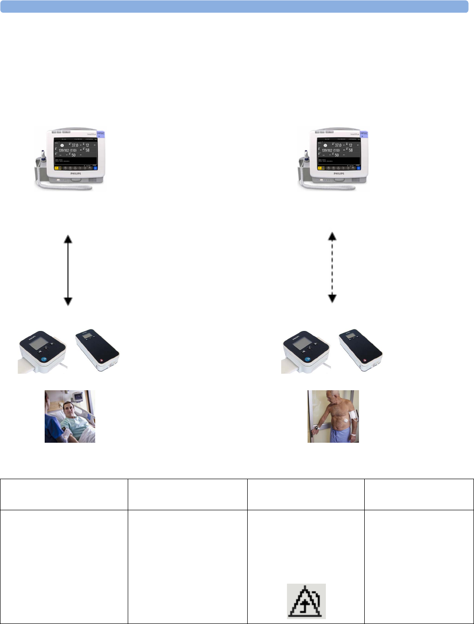
3 IntelliVue CL NBP Pod
90
Alarm Availability: Standard Use Model versus Local Attended Monitoring with CL
Measurement Alarms Off
34
Patient within Range Patient Mobile
->
Patient mobile
<-
Patient back
SRR connection no SRR connection
Action / Event Situation Alarm Availability
at CL Pod
Alarm Availability
at Patient Monitor
Connected, but no CL Alarms
(CL Measurement Alarms
Off):
normal operation,
no special action
CL Pod connected to the
patient monitor (3)
Technical alarms
(own)
No physiological alarms
No Local Alarming icon is
displayed:
Technical alarms
(own + from Pod)
Physiological alarms
(own)
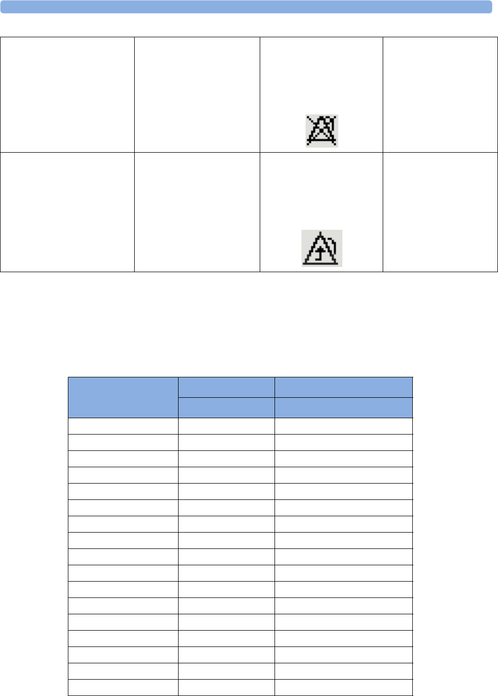
3 IntelliVue CL NBP Pod
91
NBP Default Settings
These are the most important default settings of your IntelliVue CL NBP Pod as they are delivered from the
factory. For a comprehensive list and explanation of default settings, see the Configuration Guide supplied
with your devices. The default settings can be permanently changed in Configuration Mode. When the Pod
is assigned to a patient monitor, the settings defined at the patient monitor will overwrite the settings
defined at the Pod.
Patient is leaving the vicinity
of the monitor:
no special action
Patient is mobile without
connection to the host system
(4)
Technical alarms
(own)
No physiological alarms
Alarms Off icon is displayed
in front of each numeric:
Technical alarms
(own)
Physiological alarms
(own)
No alarms from CL Pod
Patient returns to the vicinity
of the monitor:
no special action
Patient returns.
Back to connected status (3)
Technical alarms
(own)
No physiological alarms
No Local Alarming icon is
displayed:
Technical alarms
(own + from Pod)
Physiological alarms
(own + from Pod)
NBP Settings
Adult Pedi
Mode Auto Auto
Al. from Sys. Sys.
Sys.High 160 120
Dia.High 90 70
MeanHigh 110 90
Sys. Low 90 70
Dia. Low 50 40
Mean Low 60 50
Alarms On On
NBP On On
Repeat Time 10 min 10 min
Pulse On On
Unit mmHg mmHg
Done Tone Off Off
Start Time Synchronized Synchronized
VP Pressure 60 mmHg 40 mmHg
Reference Auscultatory Auscultatory

3 IntelliVue CL NBP Pod
92
Integrated Battery Handling
Only qualified and authorized service personnel (biomedical engineers or technicians) should change
batteries.
Battery Care
Battery care begins when you receive a new IntelliVue Cableless Measurement Device with built-in battery
and continues throughout the life of the device. The table below lists battery care activities and when they
should be performed.
Handling Precautions
Lithium ion batteries store a large amount of energy in a small package. Use caution when handling the
IntelliVue Cableless Measurement Devices with built-in battery; misuse or abuse could cause bodily injury
and/or property damage.
• Handle with care.
• Do not expose the device to liquids.
• Do not attempt to disassemble the device.
• Do not put device in autoclave.
• Damaged devices should not be used anymore.
WARNING
• Do not crush or puncture - mechanical abuse can lead to internal damage and internal short circuits
which may not be visible externally.
• Do not incinerate the devices or expose them to temperatures above 60°C (140°F).
Aging Time 10 min 10 min
Color Red Red
AnnouncementTone Off Off
Automatic Start Off Off
Accelerated Msmt Off Off
NBP Settings
Adult Pedi
Activity When to perform
Perform a visual inspection Before using the IntelliVue Cableless Measurement Device
Charge the battery Upon receipt, after use, or if a low battery state is indicated. To
optimize performance, a fully (or almost fully) discharged
battery should be charged as soon as possible.
Store the device in a state of charge in the
range of 40-50% and power off the device
completely.
When not in use for an extended period of time, or when the
device is shipped.

3 IntelliVue CL NBP Pod
93
Storage
If unused IntelliVue Cableless Measurement Devices are stored for an extended period of time:
• they should be powered off for storage
• they should be stored in a cool place, ideally between 15°C and 25°C (60°F and 77°F)
• the state of charge should be between 40 and 50%
• they should be recharged every six months
Storing in a cool place slows the aging process of the batteries. They should be fully charged prior to use.
Do not store the device at a temperature outside the range of -20°C (-4°F) to 60°C(140°F).
Do not store cableless devices in direct sunlight.
NOTE
Storing the devices at temperatures above 40°C (104°F) for extended periods of time could significantly
reduce the battery's life expectancy.
Battery Lifetime Management
The lifetime of a Lithium Ion battery depends on the frequency and duration of use. When properly cared
for, the useful life is approximately 4 years or 400 complete charge-discharge cycles, whichever comes first.
In addition, experience indicates that the incidence of failure may increase with battery service life due to the
accumulated stresses of daily use. We therefore strongly recommend that lithium ion batteries be replaced
after 4 years or 400 complete charge-discharge cycles.
To see the date of manufacture and the number of charge-discharge cycles:
1Select the Battery Smartkey or Main Setup followed by Battery.
2Press the hardkey to view the battery details.
The date of manufacture and the number of charge-discharge cycles are listed with other battery data on the
screen. Use the ◄ hardkey to scroll through the list.
The age of a lithium ion battery begins at the date of manufacture.
Accessories
You can order parts and accessories from Philips supplies at www.medical.philips.com or consult your local
Philips representative for details. Also consult the accessories' Instructions for Use, if available.
WARNING
Reuse: Never reuse single-patient sensors, accessories and so forth that are intended for single use, or
single patient use only. Reuse may compromise device functionality and system performance and cause a
potential hazard, in particular with regard to cross-contamination.
Philips’ approval: Use only Philips-approved accessories. Using non-Philips-approved accessories may
compromise device functionality and system performance and cause a potential hazard.
Accessories Compliant with EMC Standards
All accessories listed in the accessories sections comply, in combination with the IntelliVue Cableless
Measurements, with the requirements of IEC 60601-1-2.

3 IntelliVue CL NBP Pod
94
IntelliVue CL NBP Pod Accessories
Mobile CL Cuffs and Accessories
Comfort Care Reusable Cuffs
Part Number Description Limb
Circumference
Range
Contents
989803163171 Mobile CL Reusable Small Adult
Cuff
21 - 27 cm 1 cuff
989803163191 Mobile CL Reusable Adult Cuff 26.0 - 34.5 cm 1 cuff
989803163211 Mobile CL Reusable Large Adult
Cuff
33.5 - 45.0 cm 1 cuff
989803163181 Mobile CL Single-Patient Small
Adult Cuff
21 - 27 cm 20 cuffs
989803163201 Mobile CL Single-Patient Adult
Cuff
26.0 - 34.5 cm 20 cuffs
989803163221 Mobile CL Single-Patient Large
Adult Cuff
33.5 - 45.0 cm 20 cuffs
989803163251 Mobile CL NBP Cradle Kit - 20 cradles
989803163131 Mobile CL Extension Air Hose,
1.0 m
- 1 extension air hose
989803187431 Mobile CL Air Hose - Bayonet
Connector
- 1 adapter air hose
989803163261 Mobile CL NBP Battery Kit - 1 Battery
1 disassembly tool
1 front housing
989803137831 Telemetry Pouch with window - 50 pouches
989803140371 Telemetry Pouch with window - 4 boxes of
50 pouches
989803101971
(9300-0768-050)
White Telemetry Pouch with
Snaps; box of 50
- 50 pouches
989803101981
(9300-0768-200)
White Telemetry Pouch with
Snaps; 4 boxes of 50
- 4 boxes of
50 pouches
Part Number Description Limb Circumference Range
M1571A Infant cuff 10.0 - 15.0 cm
M1572A Pediatric cuff 14.0 - 21.5 cm
M1573A Small adult cuff 20.5 - 28.0 cm
M1573XL Small adult cuff, XL 20.5 - 28.0 cm
M1574A Adult cuff 27.0 - 35.0 cm
M1574XL Adult cuff, XL 27.0 - 35.0 cm
M1575A Large adult cuff 34.0 - 43.0 cm
M1575XL Large adult cuff, XL 34.0 - 43.0 cm

3 IntelliVue CL NBP Pod
95
Easy Care Reusable Cuffs
Multi Care Cuffs
M1576A Thigh cuff 42.0 - 54.0 cm
M1577A Kit of small cuffs (M1571A to M1574A)
M1578A Kit of large cuffs (M1573A to M1576A)
M1579A Kit of all cuffs (M1571A to M1576A)
Part Number Description Limb Circumference Range
Part Number Description Limb Circumference Range
M4552B Infant cuff 10.0 - 15.0 cm
M4552B5 Pack of 5 M4552B cuffs
M4553B Pediatric cuff 14.0 - 21.5 cm
M4553B5 Pack of 5 M4553B cuffs
M4554B Small adult cuff 20.5 - 28.5 cm
M4554B5 Pack of 5 M4554B cuffs
M4555B Adult cuff 27.5 - 36.0 cm
M4555B5 Pack of 5 M4555B cuffs
M4556B Adult cuff, XL 27.5 - 36.0 cm
M4556B5 Pack of 5 M4556B cuffs
M4557B Large adult cuff 35.0 - 45.0 cm
M4557B5 Pack of 5 M4557B cuffs
M4558B Large adult cuff, XL 35.0 - 45.0 cm
M4558B5 Pack of 5 M4558B cuffs
M4559B Thigh cuff 44.0 - 56.0 cm
M4559B5 Pack of 5 M4559B cuffs
864288 Assortment pack of one small adult, one adult, one large adult
and one thigh cuff
864289 Assortment pack of one infant, one pediatric, one small adult
and one adult cuff
864290 Assortment pack of one infant, one pediatric, one small adult,
one adult, one large adult and one thigh cuff
864291 Assortment pack of one small adult, one adult, one adult XL,
one large adult, one large adult XL and one thigh cuff
Part Number Description Limb Circumference Range
989803183311 Infant cuff 10.0 - 15.0 cm
989803183321 Pediatric cuff 14.0 - 21.5 cm
989803183331 Small adult cuff 20.5 - 28.0 cm
989803183341 Adult cuff 27.0 - 35.0 cm
989803183351 Adult cuff, XL 27.0 - 35.0 cm

3 IntelliVue CL NBP Pod
96
Single Patient, Gentle Care Cuffs
Single Care Cuffs
Value Care Cuffs
989803183361 Large adult cuff 34.0 - 43.0 cm
989803183371 Thigh cuff 42.0 - 54.0 cm
Part Number Description Limb Circumference Range
Part Number Description Limb Circumference Range
M4572B Infant cuff 10.0 - 15.0 cm
M4573B Pediatric cuff 14.0 - 21.5 cm
M4574B Small adult cuff 20.5 - 28.5 cm
M4575B Adult cuff 27.5 - 36.0 cm
M4576B Adult cuff, XL 27.5 - 36.0 cm
M4577B Large adult cuff 35.0 - 45.0 cm
M4578B Large adult cuff, XL 35.0 - 45.0 cm
M4579B Thigh cuff 44.0 - 56.0 cm
Part Number Description Limb Circumference Range
989803182281 Pediatric cuff 14.0 - 21.5 cm
989803182291 Small adult cuff 20.5 - 28.5 cm
989803182301 Adult cuff 27.5 - 36.0 cm
989803182311 Adult cuff, XL 27.5 - 36.0 cm
989803182321 Large adult cuff 35.0 - 45.0 cm
Part Number Description Limb Circumference Range
989803160811 Infant cuff 10.0 - 15.0 cm
989803160821 Pediatric cuff 14.0 - 21.5 cm
989803160831 Small adult cuff 20.5 - 28.5 cm
989803160841 Adult cuff 27.0 - 35.0 cm
989803160851 Adult cuff, XL 27.0 - 35.0 cm
989803160861 Large adult cuff 34.0 - 43.0 cm

3 IntelliVue CL NBP Pod
97
Maintenance and Troubleshooting
WARNING
Schedule: Failure on the part of the responsible individual hospital or institution employing the use of this
equipment to implement a satisfactory maintenance schedule may cause undue equipment failure and
possible health hazards.
Contact: If you discover a problem with any of the equipment, contact your service personnel, Philips, or
your authorized supplier.
Inspecting the Equipment and Accessories
You should perform a visual inspection before every use, and in accordance with your hospital's policy.
With the device switched off:
1Examine unit exteriors for cleanliness and general physical condition. Make sure that the housings are
not cracked or broken, that everything is present, that there are no spilled liquids and that there are no
signs of abuse.
2Inspect all accessories (cables, sensors and so forth). If any show signs of damage, do not use them.
WARNING
If the IntelliVue Cableless Measurement Device is mechanically damaged, or if it is not working properly,
do not use it for any monitoring procedure on a patient, contact your service personnel.
Maintenance Task and Test Schedule
All maintenance tasks and performance tests are documented in detail in the service documentation
supplied on the IntelliVue Cableless Measurements documentation DVD. These tasks are for Philips-
qualified service professionals only.
Ensure that these tasks are carried out as indicated by the device's maintenance schedule, or as specified by
local laws. Contact a Philips-qualified service provider if your device needs a safety or performance test.
Clean and disinfect equipment to decontaminate it before testing or maintaining it.
Troubleshooting
If a device will not switch on when you press a key, place it onto a charger slot on the charging station.
If you suspect a problem with an individual measurement device, read the Instructions for Use and
double check that you have set up the measurement correctly. Check also that the measurement has not
been switched off at the patient monitor that the device is assigned to.
If you suspect an intermittent, system-wide problem call your service personnel.

3 IntelliVue CL NBP Pod
98
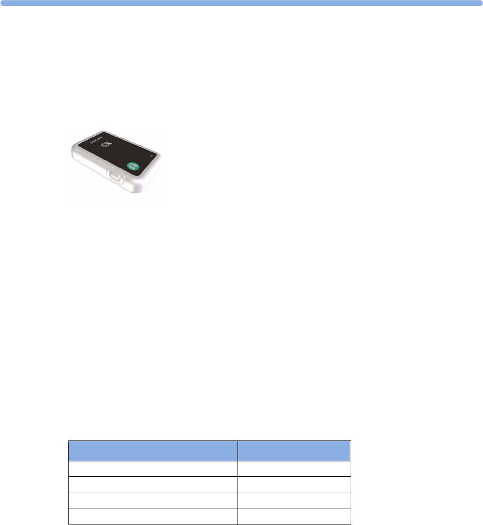
4
99
4IntelliVue CL Respiration Pod
For respiration measurement, attach the Cableless Respiration Pod to the patient's left costal arch using the
Mobile CL Respiration Pod Attachment. As an option, the Respiration Pod also provides pulse
measurement. The CL Respiration Pod also provides information about patient posture (positions like
supine, prone, upright,...) and activity (e.g. very high or very low activity).
For details regarding the adhesive attachment (Mobile CL Respiration Pod Attachment), refer to “IntelliVue
CL Respiration Pod Accessories” on page 111.
General Operation of the Respiration Pod
The IntelliVue CL Respiration Pod does not have a display and is generally operated via the host system
(e.g. patient monitor). The Pod reports the measured values and status information to the host system via
SRR.
The IntelliVue CL Respiration Pod has a multi-color LED and a single operation key to display states and
allow some basic operation locally.
Putting the Pod into Operation
The first time a CL Respiration Pod is used, place it on the IntelliVue CL Charging Station. This will
automatically switch the device on, and the device will become visible to the host (patient monitor or
GuardianSoftware).
Checking the Battery Status
Press the key once to check the battery status:
If the LED is blinking, this means that the Pod is currently not assigned to a host.
Status LED
Battery OK green
Battery low yellow
Battery empty red
Battery or system malfunction cyan

4 IntelliVue CL Respiration Pod
100
Recharging the Pod
To recharge the pod, place it on the charging station. During loading, the pod's LED shows the status:
Power Off
To power off the IntelliVue CL Respiration Pod, take the device from the charging station, then press and
hold the key on the pod for five seconds until the LED blinks red. Release the key and press it again to
confirm power off. The LED will switch to solid red and fade out. To switch it back on, you must place the
device on a charging station. Use this option when the device is not used for a longer time or prepared for
storage or shipping.
Connection with Host Systems
The following sections describe how the IntelliVue Cableless Measurement Devices work together with
host systems (Patient Monitors or GuardianSoftware).
IntelliVue Cableless Measurements Use Models
With these patient-worn measurement devices you can measure and transmit a patient's vitals regularly or
on an intermittent data collection basis. There are two typical use models:
With a Patient Monitor
The IntelliVue Cableless Measurement Devices can be used together with an MP5/MP5SC/MP5T, MP2 or
X2 patient monitor (with an SRR interface). They can communicate their measurement values via short
range radio to the monitor. The monitor may be assigned to a patient sector at the IntelliVue Information
Center (IIC). When assigned to the Information Center, certain actions can be performed at both the
patient monitor and the Information Center. See the table “Controls Available with a Patient Monitor” on
page 102.
In situations where patients are becoming more mobile (for example, in step-down/intermediate care units)
the lightweight Cableless Measurement Devices allow increased mobility within the short range radio range,
without giving up vital signs monitoring.
A telemetry device can be assigned to a patient monitor equipped with short range radio at the same time as
any Cableless Measurement Devices are also assigned to this monitor.
If the connection between the monitor and the Cableless Measurement Device is lost, an INOP will be
displayed at the monitor: cl Resp Disconnect.
With IntelliVue GuardianSoftware
The Cableless Measurement Devices can be used together with IntelliVue GuardianSoftware.
GuardianSoftware collects non-continuous vital signs data that are transmitted via a Transmitter, Hotspot
or MP5 from the Cableless Measurement Devices. Using the collected data, it provides trending, review,
reporting and notification. The Guardian Early Warning Scoring (Guardian EWS) application provides
basic assessment guidance, helping you to recognize the early signs of deterioration in your patients.
GuardianSoftware is not intended for monitoring in combination with Cableless Measurement Devices.
Some of the measurement tasks can be performed remotely from GuardianSoftware. See the table
“Controls Available with GuardianSoftware” on page 103. GuardianSoftware also manages the patient data.
If the connection between GuardianSoftware and the Cableless Measurement Device is lost, the connection
symbol will be displayed gray at GuardianSoftware.
Status LED
Battery full (≥90%) green
Battery loading yellow
Battery malfunction cyan

4 IntelliVue CL Respiration Pod
101
Device Compatibility
The IntelliVue CL Respiration Pod requires the following software levels in the associated equipment:
• Patient Monitor - Release J.2 or above
• IntelliVue GuardianSoftware - Revision B.0 or above
The IntelliVue CL Respiration Pod Pediatric Mode requires the following software levels in the associated
equipment:
• Patient Monitor - Release M.0 or above
• IntelliVue GuardianSoftware - Revision D.0 or above
Availability of Patient Alarms
When the IntelliVue CL Respiration Pod is assigned to a host and a short range radio connection exists,
alarms will be announced at the host device.
•When assigned to a patient monitor: Alarm messages will be displayed and audible alarm indicators
sounded at the patient monitor in the same way and under the same conditions as for its own
measurements. See the Instructions for Use of the patient monitor for details.
•When assigned to GuardianSoftware: Measurement values sent via transmitter, hotspot or MP5 to
IntelliVue GuardianSoftware will be visualized in GuardianSoftware. Since IntelliVue GuardianSoftware
is a data management system, no alarms are derived. The IntelliVue Cableless Measurement Devices
will also not generate physiological alarms when connected to IntelliVue GuardianSoftware. See the
Instructions for Use of GuardianSoftware.
Assigning an IntelliVue Cableless Measurement Device to a Host
When an IntelliVue CL Respiration Pod is used with a host system (patient monitor or GuardianSoftware),
the Pod must be assigned to that host system.
The assignment must be done at the host system.
WARNING
Always make sure that the applied CL Respiration Pod is assigned to the correct patient.
WARNING
Short Range Radio connections are subject to interruption due to interference from other radio sources in
the vicinity, including microwaves, bluetooth devices, WLAN devices (802.11b,g,n) and cordless phones.
Depending on the strength and duration of the interference, the interruption may occur for an extended
period. A loss of connection, due to moving out-of-range, interference, or for other reasons, is indicated
with a cl Resp Disconnect INOP at the host monitor. Correct channel configuration is important, refer to
the Configuration Guide for details.

4 IntelliVue CL Respiration Pod
102
Assignment at the Patient Monitor
Manual Assignment
Prepare the Pod for assignment by pressing the hardkey once (LED shows battery and assignment status).
At the patient monitor,
1Open the Add cl Measurement window, e.g. by using the measurement selection key followed by the
Add cl Msmt pop-up key.
The available Cableless Measurement Devices are shown in the window.
2Select the device which you want to assign to the patient on the monitor.
3The monitor displays the assignment prompt message.
When the Cableless Measurement Device is assigned, the LED changes from blinking to solid.
An assigned Cableless Measurement Device can be removed in the Measurement Selection window. For
more details see the Instructions for Use for your patient monitor.
Assignment with an RFID Reader and Tagged Cableless Devices
You can directly assign all cableless devices that have RFID tags with a Philips HS1-R RFID/barcode
reader. The Respiration Pod has a built-in RFID tag.
1Hold the cableless device close to the reader.
Depending on its configuration, the reader beeps, vibrates or indicates via the LEDs when it has read
the tag.
2Press any hardkey on the cableless device.
The Cableless Measurement Device is now added to the monitor.
If a Cableless Measurement of the same type is already assigned to the monitor, you will be asked to confirm
that it should be removed by selecting Replace.
Assignment with GuardianSoftware
To assign a Cableless Measurement Device to a patient in GuardianSoftware:
1Select the patient on the Chalkboard.
2Take the Cableless Measurement Device from the charger.
3On the Equipment List tab, select the Cableless Measurement Device on the Available Equipment list,
highlighted in green on top of the list. The device on top of the list is always the one with the most
recent user interaction (taken off the charger, put on the charger, or key pressed).
4Click Use for Patient to assign the device to the patient.
Controls Available with a Patient Monitor
The controls available when working with the Cableless Measurement Device and a patient monitor are
described in the table below.
Action At the Cableless
Measurement
Device
At the Patient
Monitor
At the IIC
Start Resp/Pulse Measurement Yes Yes No
Change Measurement Mode No Yes No
Change Repetition Time No Yes No
Change Alarm Limits No Yes No
Assign Respiration Pod No Yes No

4 IntelliVue CL Respiration Pod
103
WARNING
If a patient being monitored by Cableless Measurement Devices moves out of range of the patient monitor,
the measurements are not transmitted to the patient monitor or the Information Center.
Keep the patient monitor with the patient during transport.
Controls Available with GuardianSoftware
The controls available when working with the Cableless Measurement Device and GuardianSoftware are
described in the table below.
Trending
The IntelliVue Cableless Measurement Devices provide data for trending of parameters. The trended data
are only available via a host system. For details on trends see the Instructions for Use of your host system.
When the connection to the host is lost during measurement, the IntelliVue Cableless Measurement
Devices are able to collect data in a local memory. These data can be uploaded to GuardianSoftware, but
not to other host systems, when a connection is established at a later stage.
Remove Respiration Pod Yes Yes No
Dynamic Repetition Mode On/Off No Yes No
Posture On/Off No Yes No
Activity On/Off No Yes No
Alarm Silence No Yes Yes
Alarm Off/Pause No Yes Yes
Action At the Cableless
Measurement
Device
At the Patient
Monitor
At the IIC
Action At the Cableless
Measurement Device
At GuardianSoftware
Start Resp/Pulse Measurement Yes Yes
Change Measurement Mode No Yes
Change Repetition Time No Yes
Change Alarm Limits No Yes
Assign Respiration Pod No Yes
Remove Respiration Pod Yes Yes
Dynamic Repetition Mode On/Off No Yes
Posture On/Off No Yes
Activity On/Off No Yes
Technical Alarm Silence No Yes

4 IntelliVue CL Respiration Pod
104
Monitoring Respiration
The CL Respiration Pod derives the respiration and pulse signal from the chest and abdomen movements
measured with a built-in acceleration sensor. The CL Respiration Pod gets attached with a Mobile CL
Respiration Pod Attachment to the left costal arch on the patient's chest.
When configured, the CL Respiration Pod provides information on the basic patient posture and patient
activity. Various postures such as supine, upright and lying on left/right side are detected and updated after
a posture change has occurred and posture is stable again. The activity is determined once per second, and
an average activity level between 0 and 10 is reported once per minute to the connected host system. The
activity status information provides only an approximate indication of the actual patient activity.
WARNING
The CL Respiration Pod is not an apnea monitor and does not provide apnea alarming.
Excessive patient movement can interfere with the measured signal. This may result in inaccurate
measurements.
The CL Respiration Pod does not provide continuous measurement. When configured in frequent mode,
the fastest update rate for pulse is 8 sec.
If the patient has a condition where the respiration rate approaches the upper limit of the measurement
range (60 rpm), use other means of respiration rate measurement.
Do not use the CL Respiration Pod in an environment where continuous monitoring is needed, such as
intensive care units or operating rooms, because life-critical events might be missed due to the intermittent
mode of measurement.
Do not use the CL Respiration Pod on patients with rapid, irregular heart rates greater than 110 bpm. Use
under these conditions has not been clinically validated.
Measurement Modes
There are three different modes available for performing respiration/pulse measurements: Manual Mode,
Automatic Mode and Frequent Mode. The mode can only be set on the host system:
•Manual Mode - a single respiration and pulse measurement is performed when a measurement is
started at the host or when the key on the Respiration Pod is pressed (key must be pressed twice if the
LED is off).
•Automatic Mode - respiration and pulse measurements are performed with an interval between them.
The interval is selected at the host. The first measurement starts immediately after entering the
automatic measurement mode. If configured: When the respiration rate rises above or falls below the
defined alarm limits, the measurement mode changes temporarily to frequent mode. The automatic
mode will resume if the respiration rate readings are valid for at least 1 minute and no respiration rate
reading within the last minute violates the respiration rate alarm.
•Frequent Mode - respiration and pulse measurement is active all the time. The respiration rate is
updated with every new detected breath. The shortest update interval for the pulse rate is 8 seconds.
If Dynamic Repetition is enabled (this is setting available in Configuration mode, see IntelliVue Patient
Monitor Configuration Guide for details), and the respiration rate violates the high or low respiration rate
limit, the measurement switches automatically to Frequent mode. As soon as the respiration rate values are
within the limits again, and the values are valid for at least 1 minute, Dynamic Repetition switches back to
Automatic mode.
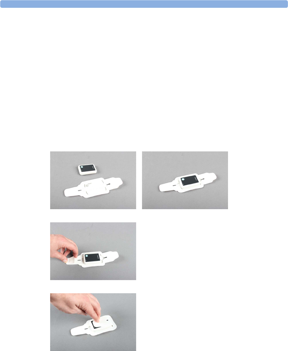
4 IntelliVue CL Respiration Pod
105
Assigning the Pod
Take the pod from the charging station. The multi-color LED blinks if the pod is not assigned to a host
system.
When working with a patient monitor:
Go to the patient monitor you want to use and select Add cl Msmt. The LED on the pod changes from
blinking to solid.
When working with GuardianSoftware:
In GuardianSoftware:
1Select the patient on the Chalkboard.
2On the Equipment List tab, select the Cableless Measurement Device on the Available Equipment list.
The LED on the Respiration pod blinks.
3Click Use for Patient to assign the pod to the patient.
Attaching the Pod to the Patient
1Put the pod front side up onto the adhesive attachment according to the positioning markers.
2Remove the protective cover from the strap with the adhesive patch.
3Fold the straps over the front of the pod, beginning with the strap that has no adhesive patch.
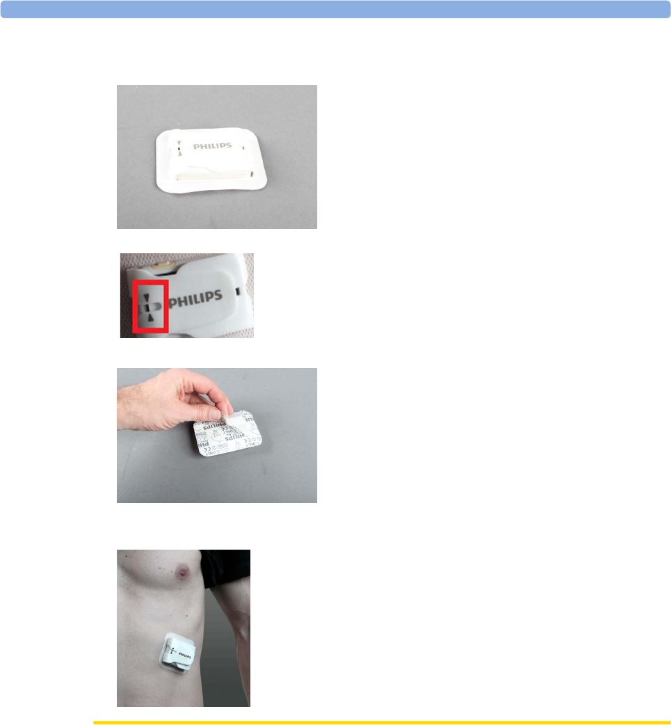
4 IntelliVue CL Respiration Pod
106
4Fold the second strap over the pod and make sure that the pod is securely and tightly enclosed by the
straps.
The arrow symbols on the upper strap must be in line with the end of the lower strap:
5Remove the protective cover from the back of the adhesive attachment.
6Place the pod on the patient's skin in the region of the left costal arch, with the operation key facing
upwards. Press down the adhesive attachment all around the pod.
CAUTION
The patient's skin should be dry, clean and free of excessive hair.
Make sure that the CL Respiration Pod is attached the right way round, with the operation key facing
upwards. Otherwise, the posture detection will not provide correct readings.

4 IntelliVue CL Respiration Pod
107
WARNING
Do not use an adhesive attachment on a patient with a history of skin irritation, allergies or hypersensitivity
to adhesives. Do not use on patients with lesions, infections or skin inflammations.
To avoid skin irritations and lacerations, periodically inspect the sensor application site and change the
application site regularly. After use, clean the patient's skin to remove residual adhesive.
Always make sure that the attached pod is assigned to the correct patient. For this purpose, it may be helpful
to put the equipment label on the pod (for example by using a stick-on label) and to write the patient name
on the adhesive attachment.
Do not reuse an adhesive attachment on another patient due to risk of cross-infection.
Measuring Respiration
If the LED is on, press the key once to start a measurement. If the LED is off, press the key twice.
Alternatively, start the measurement from the host system.
If the measurement has been started directly at the pod, the LED blinks white while the measurement is in
progress.
When the measurement has finished successfully: The LED changes to solid white.
If a measurement fails: The LED blinks white quickly.
For a description of the way the measurement results are displayed on the host (Monitor or
GuardianSoftware), see the Instructions for Use of the product used as a host.
Unassigning the Respiration Pod
To unassign the CL Respiration Pod from a host:
Put the pod on the IntelliVue CL Charging Station
or:
Keep the key pressed for 2 seconds, until the LED is blinking yellow. Press the key once more to confirm.
LED changes to solid yellow and fades out (CL Respiration Pod unassigned).
Posture and Activity Information
The CL Respiration Pod can also provide information on basic patient posture (body positions). The
patient's position is determined and the corresponding information is displayed at the host:
•Supine
•Prone
•Lying Left (lying on left side)
•Lying Right (lying on right side)
•Lying (unspecific)
•Upright
•Reclined
•Forward
•Upside Down
•Sitting
•Standing

4 IntelliVue CL Respiration Pod
108
•Rolling (in bed; example: patient is agitated)
•Walking
•Wheelchair (unassisted)
Additionally, the activity level is displayed at the host as a numerical value that ranges in normal operation
between level 1 (very low activity) and level 10 (very high activity). Activity level 0 indicates that no
physiological signal can be detected (for example when the device has fallen off and is lying on the ground).
NOTE
The information on basic patient posture and activity is not intended for monitoring or diagnostic purposes.
The basic patient posture and activity information is only for reference, showing clinical personnel the
approximate posture and activity status of the patient.
The activity level does not provide information on a specific activity pattern (e.g. if a patient is walking, or if
a patient is rolling over in bed). The activity information is also not intended to recognize abnormal body
movements caused by specific diseases, like Parkinson’s disease, or other neurological conditions.
Technical Alarms (INOPs)
Technical alarms, also known as INOPs, indicate that the measuring device cannot measure reliably. If an
INOP interrupts monitoring, there will be a question mark in place of the measurement numeric on the
host monitor.
The IntelliVue CL Respiration Pod does not provide any INOP displays or sounds locally at the device
itself. INOPs will be announced visually and audibly at the host monitor.
Some INOPs have a severity indication: !! for a medium severity INOP and !!! for a high severity INOP.
Reference List of all INOPs
INOP Message, Indication Source What to do
Can't Analyze cmRR Resp Unable to analyze respiration signal
Can't AnalyzePulse Resp Unable to analyze pulse signal
cl Resp Batt Empty
INOP tone
Battery The remaining monitoring time is below 30 minutes. Charge
battery.
cl Resp Batt Incmp
INOP tone
Battery Battery cannot be used with this Cableless Measurement
Device. Contact your service personnel.
cl Resp Batt Low
INOP tone
Battery The remaining monitoring time is below 2 hours.
cl Resp Batt Malf
INOP tone
Battery Malfunction of the battery system detected (charger circuit or
battery). Contact your service personnel.
cl Resp Batt Temp
INOP tone
Battery The temperature of the battery is critically high. Remove
Cableless Measurement Device from patient and contact your
service personnel.
cl Resp Check Batt
INOP tone
Battery The maximum number of charge/discharge cycles of the
battery will be reached in less than 50 cycles. Contact your
service personnel.
cl Resp Chk Sett
INOP tone
Resp If this INOP appears, check the Cableless Measurement
Device and patient settings before you resume taking
measurements. If the settings are unexpected, there may be a
problem with the Cableless Measurement Device software.
Contact your service personnel.

4 IntelliVue CL Respiration Pod
109
Respiration Default Settings
These are the most important default settings of your IntelliVue CL Respiration Pod as they are delivered
from the factory. For a comprehensive list and explanation of default settings, see the Configuration Guide
supplied with your devices. The default settings can be permanently changed in the Support Tool
Configuration Editor.
cl Resp Disconnect Resp The Respiration Pod has lost the SRR connection to the host.
cl Resp Remove
INOP tone
Resp The temperature of the battery is too high. Take the Cableless
Measurement Device away from the patient and contact
service personnel.
cl Resp Serv Batt
INOP tone
Battery Maximum number of charge/discharge cycles for battery
exceeded. Charging of the battery is inhibited. Contact your
service personnel.
clResp License Req Resp Unlicensed exchange device. Contact your service personnel.
cmResp NeoPatient?
Numeric is replaced by -?-
INOP tone
Resp The patient monitor the Respiration Pod is assigned to is in
neonatal mode. The INOP will remain active until the
monitor is changed to adult mode.
cmResp No Signal Resp No active signal can be detected.
cmRespCan'tAnalyze Resp Unable to analyze respiration and pulse signal
cmRespPediPatient?
Numeric is replaced by -?-
INOP tone
Resp The patient monitor the Respiration Pod is assigned to is in
pediatric mode. The INOP will remain active until the
monitor is changed to adult mode.
INOP Message, Indication Source What to do
Respiration Settings Factory Defaults
Mode Auto
Repeat Time 15 min
cmResp On
Pulse On
Dyn. Repetition Enabled
Posture Off
Activity Off
Aging Time 10 min
Color Yellow

4 IntelliVue CL Respiration Pod
110
Integrated Battery Handling
Battery Care
The IntelliVue CL Respiration Pod has a built-in battery that is not exchangeable. Battery care begins when
you receive a new pod and continues throughout the life of the pod. The table below lists battery care
activities and when they should be performed.
Handling Precautions
Lithium ion batteries store a large amount of energy in a small package. Use caution when handling the
IntelliVue Cableless Measurement Devices with built-in battery; misuse or abuse could cause bodily injury
and/or property damage.
• Handle with care.
• Do not expose the device to liquids.
• Do not attempt to disassemble the device.
• Do not put device in autoclave.
• Damaged devices should not be used anymore.
WARNING
• Do not crush or puncture - mechanical abuse can lead to internal damage and internal short circuits
which may not be visible externally.
• Do not incinerate the devices or expose them to temperatures above 60°C (140°F).
Storage
If unused IntelliVue Cableless Measurement Devices are stored for an extended period of time:
• they should be powered off for storage
• they should be stored in a cool place, ideally between 15°C and 25°C (60°F and 77°F)
• the state of charge should be between 40-50%
• they should be recharged every six months
Storing in a cool place slows the aging process of the batteries. They should be fully charged prior to use.
Do not store the device at a temperature outside the range of -20°C (-4°F) to 60°C (140°F).
Do not store cableless devices in direct sunlight.
NOTE
Storing the devices at temperatures above 40°C (104°F) for extended periods of time could significantly
reduce the battery's life expectancy.
Activity When to perform
Charge the battery Upon receipt, after use, or if a low battery state is indicated. To
optimize performance, a fully (or almost fully) discharged
battery should be charged as soon as possible.
Store the device in a state of charge in the
range of 40-50% and power off the device
completely.
When not in use for an extended period of time.

4 IntelliVue CL Respiration Pod
111
Battery Lifetime Management
The lifetime of a Lithium Ion battery depends on the frequency and duration of use. When properly cared
for, the useful life is approximately 4 years or 400 complete charge-discharge cycles, whichever comes first.
In addition, experience indicates that the incidence of failure may increase with battery service life due to the
accumulated stresses of daily use. The batteries of the IntelliVue CL Respiration Pod cannot be exchanged,
so the device itself must be replaced after 4 years or 400 complete charge-discharge cycles.
Accessories
You can order parts and accessories from Philips supplies at www.medical.philips.com or consult your local
Philips representative for details. Also consult the accessories' Instructions for Use, if available.
WARNING
Reuse: Never reuse single-patient sensors, accessories and so forth that are intended for single use, or
single patient use only. Reuse may compromise device functionality and system performance and cause a
potential hazard, in particular with regard to cross-contamination.
Philips’ approval: Use only Philips-approved accessories. Using non-Philips-approved accessories may
compromise device functionality and system performance and cause a potential hazard.
IntelliVue CL Respiration Pod Accessories
Part Number Description Contents
989803179541 Mobile CL Respiration Pod Attachment 50 attachments

4 IntelliVue CL Respiration Pod
112
Maintenance and Troubleshooting
WARNING
Schedule: Failure on the part of the responsible individual hospital or institution employing the use of this
equipment to implement a satisfactory maintenance schedule may cause undue equipment failure and
possible health hazards.
Contact: If you discover a problem with any of the equipment, contact your service personnel, Philips, or
your authorized supplier.
Inspecting the Equipment and Accessories
You should perform a visual inspection before every use, and in accordance with your hospital's policy:
Examine unit exteriors for cleanliness and general physical condition. Make sure that the housings are not
cracked or broken, that everything is present, that there are no spilled liquids and that there are no signs of
abuse.
WARNING
If the IntelliVue Cableless Measurement Device is mechanically damaged, or if it is not working properly,
do not use it for any monitoring procedure on a patient, contact your service personnel.
Maintenance Task and Test Schedule
All maintenance tasks and performance tests are documented in detail in the service documentation
supplied on the IntelliVue Cableless Measurements documentation DVD. These tasks are for Philips-
qualified service professionals only.
Ensure that these tasks are carried out as indicated by the device's maintenance schedule, or as specified by
local laws. Contact a Philips-qualified service provider if your device needs a safety or performance test.
Clean and disinfect equipment to decontaminate it before testing or maintaining it.
Troubleshooting
If the status LED does not light up when you press a key, place the device onto a charger slot on the
charging station.
If you suspect a problem with an individual measurement device, read the Instructions for Use and
double check that you have set up the measurement correctly. Check also that the measurement has not
been switched off at the patient monitor that the device is assigned to.
If you suspect an intermittent, system-wide problem call your service personnel.
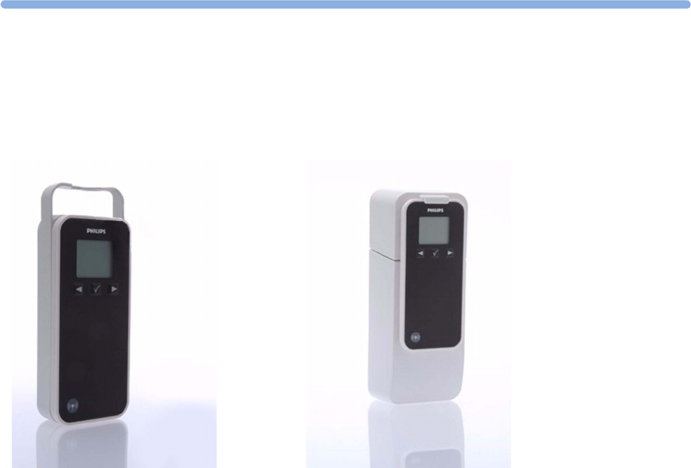
5
113
5Cableless Measurement Auxiliary Devices
IntelliVue CL Transmitter and IntelliVue CL Hotspot
The IntelliVue CL Transmitter and the IntelliVue CL Hotspot are auxiliary network devices that convert the
SRR radio technology from the IntelliVue CL SpO2 Pod, the IntelliVue CL NBP Pod and the IntelliVue CL
Respiration Pod into WLAN or LAN technology. This allows data from the measurement devices to be
transmitted to a PC for use with IntelliVue GuardianSoftware.
The IntelliVue CL Transmitter is a mobile device which can be worn by the patient or by an attending
caregiver. It transmits vital signs data to IntelliVue GuardianSoftware while the patient is moving around.
The display on the CL Transmitter shows only technical data that may be useful for troubleshooting system
problems.
The IntelliVue CL Hotspot serves as an access point in a fixed location, to provide communication to
IntelliVue GuardianSoftware for any CL Pods currently in its transmission area. The CL Hotspots will
normally be located in areas where mobile patients regularly pass by or spend time. When the patient comes
into the transmission area, any available measurement results will be automatically communicated to
GuardianSoftware.
The IntelliVue CL Transmitter is battery-powered while the IntelliVue CL Hotspot is powered by an
external power supply or PoE (Power over Ethernet).
IntelliVue CL Transmitter IntelliVue CL Hotspot
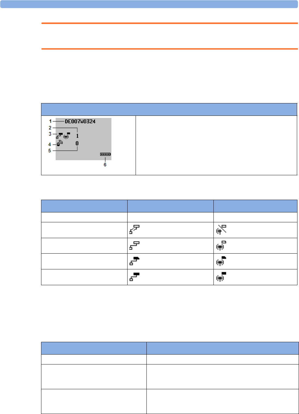
5 Cableless Measurement Auxiliary Devices
114
WARNING
The IntelliVue CL Hotspot may not be used in the patient vicinity.
Screen Layout
The CL Transmitter and CL Hotspots have the same hardkeys and display as the CL SpO2 and NBP Pods.
However, there is no user interaction required during normal operation.
This is the standard screen of a CL Transmitter or CL Hotspot:
The network status symbols show one of the following states:
CL Transmitter Integrated Battery Handling
Battery Care
Battery care begins when you receive a new IntelliVue Cableless Measurement Device with built-in battery
and continues throughout the life of the device. The table below lists battery care activities and when they
should be performed.
Screen of a CL Transmitter / CL Hotspot:
1Equipment label
2Number of GuardianSoftware Servers connected
3Network status symbols (LAN and WLAN)
4Connection status
5Number of Cableless Measurement Devices connected
6Battery gauge
State LAN symbol WLAN symbol
off - (no symbol displayed) - (no symbol displayed)
not connected
no IP address
no Guardian server connected
normally connected
Activity When to perform
Perform a visual inspection Before using the IntelliVue Cableless Measurement Device
Charge the battery Upon receipt, after use, or if a low battery state is indicated. To
optimize performance, a fully (or almost fully) discharged
battery should be charged as soon as possible.
Store the device in a state of charge in the
range of 40-50% and power off the device
completely.
When not in use for an extended period of time, or when the
device is shipped.

5 Cableless Measurement Auxiliary Devices
115
Handling Precautions
Lithium ion batteries store a large amount of energy in a small package. Use caution when handling the
IntelliVue Cableless Measurement Devices with built-in battery; misuse or abuse could cause bodily injury
and/or property damage.
• Handle with care.
• Do not expose the device to liquids.
• Do not attempt to disassemble the device.
• Do not put device in autoclave.
• Damaged devices should not be used anymore.
WARNING
• Do not crush or puncture - mechanical abuse can lead to internal damage and internal short circuits
which may not be visible externally.
• Do not incinerate the devices or expose them to temperatures above 60°C (140°F).
Storage
If unused IntelliVue Cableless Measurement Devices are stored for an extended period of time:
• they should be powered off for storage
• they should be stored in a cool place, ideally between 15°C and 25°C (60°F and 77°F)
• the state of charge should be between 40 and 50%
• they should be recharged every six months
Storing in a cool place slows the aging process of the batteries. They should be fully charged prior to use.
Do not store the device at a temperature outside the range of -20°C (-4°F) to 60°C(140°F).
Do not store cableless devices in direct sunlight.
NOTE
Storing the devices at temperatures above 40°C (104°F) for extended periods of time could significantly
reduce the battery's life expectancy.
Battery Lifetime Management
The lifetime of a Lithium Ion battery depends on the frequency and duration of use. When properly cared
for, the useful life is approximately 4 years or 400 complete charge-discharge cycles, whichever comes first.
In addition, experience indicates that the incidence of failure may increase with battery service life due to the
accumulated stresses of daily use. We therefore strongly recommend that lithium ion batteries be replaced
after 4 years or 400 complete charge-discharge cycles.
To see the date of manufacture and the number of charge-discharge cycles:
1Select the Battery Smartkey or Main Setup followed by Battery.
2Press the hardkey to view the battery details.
The date of manufacture and the number of charge-discharge cycles are listed with other battery data on the
screen. Use the ◄ hardkey to scroll through the list.
The age of a lithium ion battery begins at the date of manufacture.

5 Cableless Measurement Auxiliary Devices
116
Accessories
You can order parts and accessories from Philips supplies at www.medical.philips.com or consult your local
Philips representative for details. Also consult the accessories' Instructions for Use, if available.
WARNING
Reuse: Never reuse single-patient sensors, accessories and so forth that are intended for single use, or
single patient use only. Reuse may compromise device functionality and system performance and cause a
potential hazard, in particular with regard to cross-contamination.
Philips’ approval: Use only Philips-approved accessories. Using non-Philips-approved accessories may
compromise device functionality and system performance and cause a potential hazard.
IntelliVue CL Transmitter Accessories
Order Number Description Contents
989803168881 Mobile CL 20 Transmitter Cradle Kit 20 Single-Patient cradles and straps
989803168871 Mobile CL Transmitter Battery Kit 1 Battery
1 disassembly tool
1 front housing
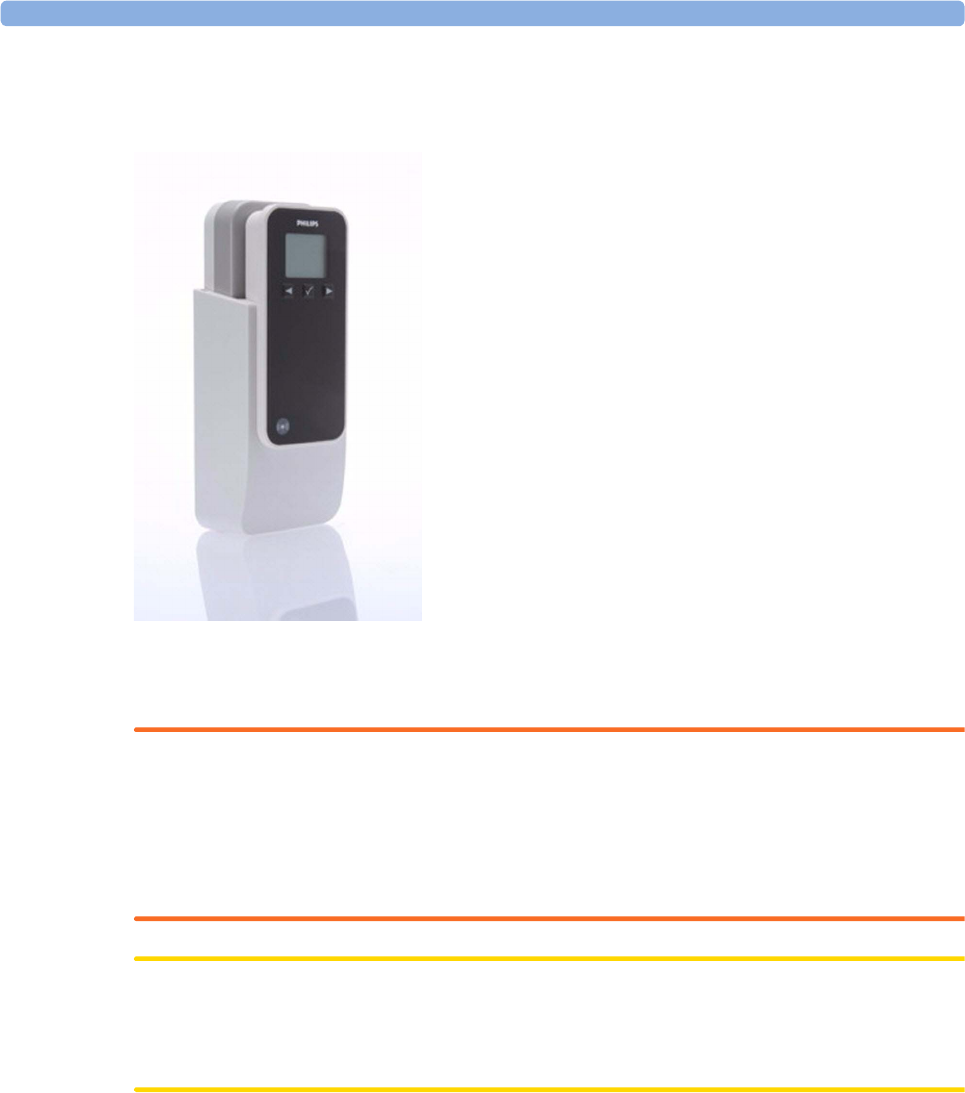
5 Cableless Measurement Auxiliary Devices
117
IntelliVue CL Transmitter Base Station
(shown here with the transmitter inserted)
The IntelliVue CL Transmitter Base Station is used with the IntelliVue CL Transmitter. When the patient is
in their room, the Transmitter can be inserted into the Base Station where it is powered and recharged and
also remains connected to the WLAN to communicate vital signs data.
WARNING
• The IntelliVue CL Transmitter Base Station may not be used in the patient vicinity.
• Ensure that the CL Transmitter Base Station does not come into close contact with implanted
pacemakers, to avoid magnetic interference affecting the mode of the pacemaker.
•Electrical shock hazard: Do not open the device housing. Refer all servicing to qualified service
personnel.
CAUTION
The CL Transmitter Base Station generates a magnetic field. Do not store magnetic media (such as identity
cards or credit cards with magnetic strips or magnetic tapes/disks) near to the Base Station, as the data may
be damaged.

5 Cableless Measurement Auxiliary Devices
118
IntelliVue CL Charging Station
This section contains some general information about charging IntelliVue Cableless Measurement Devices.
For detailed information about the IntelliVue CL Charging Station, please see the separate IntelliVue CL
Charging Station Instructions for Use.
Charging IntelliVue Cableless Measurement Devices
All IntelliVue Cableless Measurement Devices and Auxiliary Devices except the CL Hotspot are battery
powered and need to be recharged using the IntelliVue CL Charging Station. The batteries are built in and
can only be exchanged by trained service personnel, with the exception of the IntelliVue CL Respiration
Pod, where the whole device needs to be exchanged.
To charge a battery, place the device onto a charger slot on the charging station. The NBP Pod and
Transmitter should always be placed on one of the slots in the upper row. The battery power indicators will
supply information about the charge status.
WARNING
•Electrical shock hazard: Do not open the device housing. Refer all servicing to qualified service
personnel.
• Always use the supplied power cord with the grounded mains plug to connect the charging station to a
grounded AC mains socket. Never adapt the mains plug from the charging station to fit an ungrounded
AC mains socket.
• Do not use AC mains extension cords or multiple portable socket outlets. If a multiple portable socket
outlet without an approved isolation transformer is used, the interruption of its protective grounding
may result in enclosure leakage currents equal to the sum of the individual ground leakage currents, so
exceeding allowable limits.
• Do not connect any devices that are not supported as part of a system.
Battery Power Indicators
There are various indications which help you keep track of the battery power status:
• LEDs on the charging station slots
• battery status information on the charging station's display, the NBP/SpO2 Pod's display and the
Respiration Pod's LED
• INOP messages
• battery symbol on the patient monitor's screen (when assigned to a patient monitor)
• battery symbol in GuardianSoftware (when assigned to a patient in GuardianSoftware)
The indicators always show the remaining capacity in relation to the battery's actual maximum capacity,
which may lessen as the battery ages. You can see the actual capacity in the Battery menu.

5 Cableless Measurement Auxiliary Devices
119
Maintenance and Troubleshooting
WARNING
Schedule: Failure on the part of the responsible individual hospital or institution employing the use of this
equipment to implement a satisfactory maintenance schedule may cause undue equipment failure and
possible health hazards.
Contact: If you discover a problem with any of the equipment, contact your service personnel, Philips, or
your authorized supplier.
Inspecting the Equipment and Accessories
You should perform a visual inspection before every use, and in accordance with your hospital's policy.
With the device switched off:
1Examine unit exteriors for cleanliness and general physical condition. Make sure that the housings are
not cracked or broken, that everything is present, that there are no spilled liquids and that there are no
signs of abuse.
2Inspect all accessories (cables, sensors and so forth). If any show signs of damage, do not use them.
WARNING
If the IntelliVue Cableless Measurement Device is mechanically damaged, or if it is not working properly,
do not use it for any monitoring procedure on a patient, contact your service personnel.
Maintenance Task and Test Schedule
All maintenance tasks and performance tests are documented in detail in the service documentation
supplied on the IntelliVue Cableless Measurements documentation DVD. These tasks are for Philips-
qualified service professionals only.
Ensure that these tasks are carried out as indicated by the device's maintenance schedule, or as specified by
local laws. Contact a Philips-qualified service provider if your device needs a safety or performance test.
Clean and disinfect equipment to decontaminate it before testing or maintaining it.
Troubleshooting
If a device will not switch on when you press a key, place it onto a charger slot on the charging station.
If you suspect a problem with an individual measurement device, read the Instructions for Use and
double check that you have set up the measurement correctly. Check also that the measurement has not
been switched off at the patient monitor that the device is assigned to.
If you suspect an intermittent, system-wide problem call your service personnel.

5 Cableless Measurement Auxiliary Devices
120

6
121
6Care and Cleaning
Use only the Philips-approved substances and methods listed in this chapter to clean or disinfect your
equipment. Warranty does not cover damage caused by using unapproved substances or methods.
Philips makes no claims regarding the efficacy of the listed chemicals or methods as a means for controlling
infection. Consult your hospital’s Infection Control Officer or Epidemiologist. For comprehensive details
on cleaning agents and their efficacy refer to "Guideline for Disinfection and Sterilization in Healthcare
Facilities" issued by the U.S. Department of Health and Human Services, Public Health Service, Centers for
Disease Control, Atlanta, Georgia, 2008. See also any local policies that apply within your hospital, and
country.
General Points
Keep your IntelliVue Cableless Measurement Devices and accessories free of dust and dirt. After cleaning
and disinfection, check the equipment carefully. Do not use if you see signs of deterioration or damage. If
you need to return any equipment to Philips, decontaminate it first.
Observe the following general precautions:
• Always dilute according to the manufacturer’s instructions or use lowest possible concentration.
• Do not allow liquid to enter the case.
• Do not immerse any part of the equipment or any accessories in liquid if it is not explicitly allowed and
described in the respective accessory Instructions for Use.
• Do not pour liquid onto the charging station.
• Never use abrasive material (such as steel wool or silver polish).
WARNING
If you spill liquid on the charging station or accessories, or if any device or accessory is accidentally
immersed in liquid, contact your service personnel or Philips service engineer. Do not operate the
equipment before it has been tested and approved for further use.
Do not use flammable agents for disinfecting cableless measurement devices in an oxygen-enriched
environment, as this might lead to sudden ignition of vapors, resulting in injury to the patient or staff.

6 Care and Cleaning
122
Cleaning and Disinfecting the IntelliVue Cableless
Measurement Devices
The following instructions apply to the IntelliVue CL SpO2 Pod, the IntelliVue CL Respiration Pod, the
IntelliVue CL NBP Pod, the corresponding single patient Mobile CL Cradles and the auxiliary devices:
IntelliVue CL Charging Station, IntelliVue CL Transmitter, IntelliVue CL Transmitter Base Station and
IntelliVue CL Hotspot.
Clean with a lint-free cloth, moistened with warm water (40°C/104°F maximum) and soap, a diluted non-
caustic detergent, tenside, ammonia- or alcohol-based cleaning agent. Do not use strong solvents such as
acetone or trichloroethylene.
CAUTION
Solutions: Do not mix disinfecting solutions (such as bleach and ammonia) as hazardous gases may result.
Hospital policy: Disinfect the product as determined by your hospital’s policy only using the cleaning
agents specified below, to avoid long term damage to the cableless device.
Drying devices: Do not use heat sources, such as ovens or hairdryers, to dry the devices. Do not put the
devices in a microwave.
No sterilizing: Do not put the devices in an autoclave, they are not sterilizable.
Rinse the Pods in water, paying special attention to the contact area to remove all residues. Wipe them dry
with a clean cloth and then leave them to dry completely.
Do not allow any liquid to enter the charging station case and avoid pouring it on the charging station while
cleaning.
The wristbands used with the Mobile CL SpO2 Cradles are single-patient items and cannot be cleaned or
disinfected.
Refer to the accessory Instructions for Use for cleaning and disinfection information for SpO2 sensors.
Recommended Disinfection Agents
We recommend that you use one of the following disinfectants:
Product Name Product Type Manufacturer Dilution
Isopropanol liquid - 80%
Sodium Hypochlorite, bleach liquid - 1%
Hydrogen Peroxide liquid - 3%
6 Care and Cleaning
123
Refer to the accessory Instructions for Use for cleaning and disinfection information for SpO2 sensors and
NBP cuffs.
Disposing of the IntelliVue Cableless Measurement Devices
WARNING
To avoid contaminating or infecting personnel, the environment or other equipment, make sure you
disinfect and decontaminate the IntelliVue Cableless Measurement Devices appropriately before disposing
of them in accordance with your country's laws for equipment containing electrical and electronic parts. For
disposal of parts and accessories, where not otherwise specified, follow local regulations regarding disposal
of hospital waste.
You will find detailed disposal information on the following webpage:
www.healthcare.philips.com/main/about/Sustainability/Recycling/pm.wpd
The Recycling Passports located there contain information on the material content of the equipment,
including potentially dangerous materials which must be removed before recycling (for example, batteries
and parts containing mercury or magnesium).
Do not dispose of waste electrical and electronic equipment as unsorted municipal waste. Collect it
separately, so that it can be safely and properly reused, treated, recycled, or recovered.
For information in disposal of accessories, refer to the accessory Instructions for Use.
Bacillol® AF liquid, spray BODE Chemie GmbH According to
manufacturer's instructions
Dismozon® plus liquid BODE Chemie GmbH
Meliseptol®liquid, spray B. Braun Melsungen AG
Incidin® Foam liquid Ecolab Inc.
Oxivir® Tb Cleaner Disinfectant liquid, spray Diversey Inc.
Super Sani-Cloth®
Germicidal Disposable Wipes
wipes PDI Inc.
Sani-Cloth® Plus
Germicidal Disposable Wipes
wipes PDI Inc.
Mikrozid® Sensitive Wipes wipes Schülke & Mayr GmbH
Mikrozid® PAA Wipes wipes Schülke & Mayr GmbH
Descogen® Liquid rfu liquid Antiseptica Dr. Hans-Joachim
Molitor GmbH
Lysoformin liquid Lysoform Dr. Hans Rosemann
GmbH
Descosept PUR liquid Dr. Schumacher GmbH
Product Name Product Type Manufacturer Dilution

6 Care and Cleaning
124

7
125
7Specifications
The specifications in this section apply to the:
• IntelliVue CL SpO2 Pod
• IntelliVue CL NBP Pod
• IntelliVue CL Respiration Pod
• IntelliVue CL Charging Station
• IntelliVue CL Transmitter
• IntelliVue CL Transmitter Base Station
• IntelliVue CL Hotspot
The IntelliVue Cableless Measurement Devices might not meet the performance specification listed in this
chapter, if stored or operated outside the specified environmental conditions.
WARNING
The IntelliVue Cableless Measurement Devices are not intended for use in an MRI environment or in an
oxygen-enriched environment (e.g. hyperbaric chambers). During MR imaging, remove all IntelliVue
Cableless Measurement Devices and sensors from the patient. Induced currents could cause burns.
Indications for Use
IntelliVue CL SpO2 Pod:
The IntelliVue CL SpO2 Pod is indicated for use by health care professionals whenever there is a need for
acquisition or monitoring of physiological patient parameters SpO2 and pulse rate wirelessly.
The intended use of the IntelliVue CL SpO2 Pod when used together with a patient monitor or with a
telemetry system transceiver is for monitoring and recording of, and to generate alarms for, arterial oxygen
saturation and pulse rate of adult and pediatric patients.
The IntelliVue CL SpO2 Pod is also intended for local attended monitoring of, and to generate alarms for,
arterial oxygen saturation and pulse rate of adult and pediatric patients. Local attended monitoring refers to
situations where clinical staff is close to the patient such that acoustic alarming of the IntelliVue CL SpO2
Pod will be noticed. Example: In-hospital transport of a patient by hospital staff to a procedure room.
The IntelliVue CL SpO2 Pod is also intended for acquisition of arterial oxygen saturation and pulse rate data
of adult and pediatric patients for a clinical information management system.
The IntelliVue CL SpO2 Pod is intended for use by health care professionals inside hospitals. It is not
intended for home use. It is not a therapeutic device.

7 Specifications
126
IntelliVue CL NBP Pod:
The IntelliVue CL NBP Pod is indicated for use by health care professionals whenever there is a need for
acquisition or monitoring of physiological patient parameters noninvasive blood pressure and pulse rate
wirelessly.
The intended use of the IntelliVue CL NBP Pod when used together with a patient monitor or with a
telemetry system transceiver is for monitoring and recording of, and to generate alarms for, systolic,
diastolic, and mean pressure and pulse rate of adult and pediatric patients.
The IntelliVue CL NBP Pod is also intended for local attended monitoring of, and to generate alarms for,
systolic, diastolic, and mean pressure, and to measure pulse rate of adult and pediatric patients. Local
attended monitoring refers to situations where clinical staff is close to the patient such that acoustic
alarming of the IntelliVue CL NBP Pod will be noticed. Example: In-hospital transport of a patient by
hospital staff to a procedure room.
The IntelliVue CL NBP Pod is also intended for acquisition of systolic, diastolic, and mean pressure and
pulse rate data of adult and pediatric patients for a clinical information management system.
The IntelliVue CL NBP Pod is intended for use by health care professionals inside hospitals. It is not
intended for home use. It is not a therapeutic device.
IntelliVue CL Respiration Pod:
The IntelliVue CL Respiration Pod is indicated for use by health care professionals whenever there is a need
for intermittent or spot-check acquisition and monitoring of physiological patient parameters respiration
rate and pulse rate wirelessly in specific hospital areas. The IntelliVue CL Respiration Pod is mainly
indicated for use in general medical and surgery wards and in waiting areas of emergency rooms. It is not
indicated for use in hospital areas in which continuous patient monitoring is needed, such as intensive care
units or operating rooms.
The intended use of the IntelliVue CL Respiration Pod when used together with a patient monitor is for
intermittent or spot-check monitoring and recording of, and to generate alarms for, respiration rate and
pulse rate of adult and pediatric patients.
The IntelliVue CL Respiration Pod is also intended for acquisition of respiration rate and pulse rate data of
adult and pediatric patients for a clinical information management system.
The IntelliVue CL Respiration Pod is intended for use by health care professionals. It is not intended for
home use. It is not a therapeutic device.
The IntelliVue CL Respiration Pod is not intended for use on patients with extremely high values for
respiration rate (above 60 rpm).
The IntelliVue CL Respiration Pod is not intended for use on acutely ill cardiac patients with the potential
to develop life threatening arrhythmias, e.g. very fast atrial fibrillation or ventricular tachycardia (rapid
irregular pulse rate). For monitoring of these patients, a device for continuous ECG monitoring is
necessary. The IntelliVue CL Respiration Pod is not a substitute for an ECG monitor.
WARNING
Do not use the CL Respiration Pod on patients with rapid, irregular heart rates greater than 110 bpm. Use
under these conditions has not been clinically validated.
Rx only: US Federal Law restricts these devices to sale by or on the order of a physician.
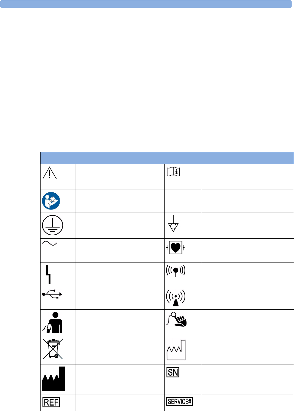
7 Specifications
127
Compatible Medical Devices
• IntelliVue Patient Monitors MP5/MP5SC/MP5T, MP2 or X2
• IntelliVue Telemetry System Transceivers TRx4841A/TRx4851A and MX40 wearable patient
monitors1
• Avalon Fetal Monitors1
• Clinical information management system: IntelliVue GuardianSoftware
1 not compatible with the CL Respiration Pod
Compatible Medical Devices supporting local attended monitoring together with CL SpO2 and
NBP Pods:
• IntelliVue Patient Monitors MP5/MP5SC/MP5T
Symbols
These symbols can appear on the IntelliVue Cableless Measurement Devices.
Symbols
Caution is necessary when operating
the device.
Operating instructions should be
considered when operating the
device.
Follow instructions for use.
Protective earth Equipotential grounding
Alternating current Connector has special protection
against electric shocks and is
defibrillator proof
Error LED Built-in wireless network (WLAN)
USB interface Non-ionizing radiation symbol
NBP identifier SpO2 identifier
Always use separate collection for
waste electrical and electronic
equipment (WEEE)
Indicates manufacturing date
Indicates location of the date of
manufacture and/or name and
address of manufacturer
Indicates location of serial number
Indicates location of catalog number Indicates location of service number
7 Specifications
128
Followed by two alphanumeric
characters, indicates ingress
protection grade
China RoHS
Do not reuse LAN connection indicator for
connection to a wired network
Resp identifier Not made with natural rubber latex
Mass in kilogram (kg) RCM compliance mark
EAC mark CSA US mark
FCC ID Federal Communications
Commission: FCC ID xxxx
CMIIT ID Chinese Radio marking: CMIIT ID
(China Ministry of Industry and
Information Technology)
CE marking accompanied by the
Notified Body number 0123
Symbols
IC-ID (Industry Canada ID)
One IC-ID labeling for each built in radio: OBR, SRR
Japanese Radio marking: Radio mark + [R]-symbol + ID
Taiwan Radio Label (NCC Logo) + ID
Korea radio mark: KC logo, KCC ID number, and
Conformity assessment information

7 Specifications
129
Manufacturer's Information
You can write to Philips at this address
Philips Medizin Systeme Boeblingen GmbH
Hewlett-Packard-Str. 2
71034 Boeblingen
Germany
Australia Sponsor:
Philips Electronics Australia Ltd
65 Epping Road,
North Ryde, NSW Australia 2113
Visit our website at: www.healthcare.philips.com.
© Copyright 2017. Koninklijke Philips N.V. All Rights Reserved.
Regulatory and Safety Specifications
General Conditions for Cableless Measurements
The IntelliVue Cableless Measurements are compliant with IEC 60601-1 Ed. 3. However, they can still be
used with IntelliVue Patient Monitors MP5/MP5SC/MP5T, MP2/X2, Avalon Fetal Monitors, IntelliVue
Telemetry System Transceivers TRx4841A/TRx4851A, MX40 wearable patient monitors, that are
compliant with IEC 60601-1 Ed. 2.
IntelliVue CL SpO2 Pod, CL NBP Pod and CL Respiration Pod:
0123
IntelliVue CL Charging Station and CL Transmitter:
The IntelliVue CL SpO2 Pod, CL NBP Pod, CL Respiration Pod, CL Charging Station, and CL Transmitter
comply with the Medical Device Directive 93/42/EEC.
In addition, the IntelliVue CL SpO2 Pod, CL NBP Pod, CL Respiration Pod, CL Charging Station and CL
Transmitter comply with:
IEC 60601-1:2005 + Cor.1:2006 + Cor.2:2007+ A1:2012; EN 60601-1:2006+ AC:2010+ A1:2013; ANSI/
AAMI ES60601-1:2005/(R)2012; CAN/CSA C22.2 No. 60601-1-14
The possibility of hazards arising from software errors was minimized in compliance with:
ISO 14971:2007; EN ISO 14971:2012, IEC 60601-1-4:1996 + A1:1999; EN 60601-1-4:1996 + A1:1999;
IEC 60601-1-6:2010 / EN 60601-1-6:2010; IEC 60601-1-8:2006+A1:2012 / EN 60601-1-
8:2007+AC:2010; IEC 60601-2-49:2011 / EN 60601-2-49:2001 (NBP Pod and SpO2 Pod only).
Classification (according to IEC 60601-1):
IntelliVue CL SpO2 Pod, CL NBP Pod, CL Respiration Pod: Internally powered equipment, Type CF,
Continuous Operation
IntelliVue CL Transmitter: Internally powered equipment, Continuous Operation
IntelliVue CL Charging Station: Class I equipment, Continuous Operation
IntelliVue CL Transmitter Base Station and CL Hotspot:

7 Specifications
130
The IntelliVue CL Transmitter Base Station and CL Hotspot comply with the Low Voltage Directive 2014/
35/EC.
In addition, these devices comply with:
IEC 60950-1:2005; EN 60950-1:2006+A11:2009 +A1:2010 +A12:2011 +A2:2013.
EMC and Radio Regulatory Compliance
FCC and Industry Canada Radio Compliance
IntelliVue CL SpO2 Pod, CL NBP Pod, CL Respiration Pod, CL Charging Station, CL Transmitter
This ISM device complies with Canadian ICES-001. Cet appareil ISM est conforme à la norme NMB-001
du Canada.
IntelliVue CL Transmitter Base Station
This Class B digital apparatus complies with Canadian ICES-003. Cet appareil numérique de la classe B est
conforme à la norme NMB-003 du Canada.
IntelliVue CL Hotspot
This Class A digital apparatus complies with Canadian ICES-003. Cet appareil numérique de la classe A est
conforme à la norme NMB-003 du Canada.
These devices comply with Part 15 of the FCC Rules and RSS-210 of Industry Canada. Operation is subject
to the following two conditions: (1) these devices may not cause harmful interference, and (2) these devices
must accept any interference received, including interference that may cause undesired operation. Any
changes or modifications to this equipment not expressly approved by Philips Medical Systems may cause
harmful radiofrequency interference and void your authority to operate this equipment.
Usage of license-exempt local area network (LE-LAN) in Canada:
IntelliVue CL Transmitter and CL Hotspot
The maximum antenna gain permitted (for devices in the bands 5250-5350 MHz and 5470-5725 MHz)
complies with the e.i.r.p. limits as stated in RSS-210.
The maximum antenna gain permitted (for devices in the 5725-5825 MHz band) complies with the
e.i.r.p. limits specified for point-to-point operation, as stated in RSS-210.
The device for the band 5150-5250 MHz is only for indoor usage to reduce potential for harmful
interference to co-channel mobile satellite systems.
CAUTION
High power radars are allocated as primary users (meaning they have priority) of the bands 5250-5350 MHz
and 5650-5850 MHz and these radars could cause interference and/or damage to LE-LAN devices.
Japanese Radio Law and Japanese Telecommunications Business Law Compliance
IntelliVue CL Respiration Pod and CL Hotspot

7 Specifications
131
R&TTE Directive Compliance
IntelliVue CL SpO2 Pod, CL NBP Pod, CL Respiration Pod, and CL Charging Station
IntelliVue CL Transmitter, and CL Hotspot
Philips Medizin Systeme Boeblingen GmbH hereby declares that these products are in
compliance with the essential requirements and other relevant provisions of Directive 1999/5/EC (Radio
and Telecommunications Terminal Equipment Directive).
The IntelliVue CL SpO2 Pod, CL NBP Pod, CL Respiration Pod, CL Charging Station, CL Transmitter,
and CL Hotspot incorporate a SRR module, which is Class 1 radio equipment.
The IntelliVue CL Transmitter and CL Hotspot incorporate additionally the IntelliVue 802.11 Adapter,
which is Class 2 radio equipment. The products are intended to be connected to the Publicly Available
Interfaces (PAI) and used throughout the EEA. Individual countries may apply restrictions on putting this
device into service or placing on the market.
To obtain a copy of the original Declaration of Conformity, please contact Philips at the address as stated in
the “Manufacturer's Information”.
WARNING
• The IntelliVue CL Charging Station is Class A professional equipment. This equipment is not intended
for use in domestic establishments or connection to the public mains network. In domestic
establishments or when connected to the public mains network, this equipment may cause radio
interference or may disrupt the operation of nearby equipment.
• The IntelliVue CL Hotspot is a Class A product. In a domestic environment this product may cause
radio interference, in which case the user may be required to take adequate measures.
• This equipment generates, uses and radiates radiofrequency energy, and if it is not installed and used in
accordance with its accompanying documentation, may cause interference to radio communications.
• The device, equipped with a wireless network interface, intentionally receives RF electromagnetic
energy for the purpose of its operation. Therefore, other equipment may cause interference, even if that
other equipment complies with CISPR emission requirements.
EMC Directive Compliance
IntelliVue CL Transmitter Base Station and CL Hotspot
The IntelliVue CL Transmitter Base Station and CL Hotspot comply with the EMC Directive 2014/
30/EC.
In addition these devices comply with:
ETSI EN 301 489-1:V1.9.2, ETSI EN 301 489-17:V2.2.1
CISPR 22:2008 / EN55022:2010/AC 2011 and CISPR 24:2010 / EN55024:2010

7 Specifications
132
Radiofrequency Radiation Exposure Information
IntelliVue CL Transmitter
For body worn operation, this device has been tested and meets FCC RF exposure guidelines when used in
the standard configuration with the rear side towards the body, without a gap. Alternatively, it can be used
with any accessory that positions the front side of the device a minimum of 10 mm from the body. The
accessory itself must not contain any metal parts. Use of other accessories may not ensure compliance with
FCC RF exposure guidelines.
Nevertheless it is strongly recommended to operate the CL Transmitter with the rear side towards the body
to achieve best possible radio performance.
Safety and Performance Tests
You must follow and apply any national regulations on the qualification of the testing personnel and suitable
measuring and testing facilities. Required safety and performance tests, and what to do if the Cableless
Measurements do not meet these specifications, are described in the IntelliVue Cableless Measurements
Service Guide.
Electromagnetic Compatibility (EMC)
Take special precautions regarding electromagnetic compatibility (EMC) when using the IntelliVue
Cableless Measurements. Operate the IntelliVue Cableless Measurements according to the EMC
information provided in these Instructions for Use and in the IntelliVue Cableless Measurements Service
Guide. Portable and mobile radiofrequency (RF) communications equipment can affect the IntelliVue
Cableless Measurements.
WARNING
For paced patients: The radiated SRR power of the IntelliVue SpO2, NBP and Respiration Cableless
Measurement Devices, the CL transmitter, and other sources of radiofrequency energy, when used in very
close proximity of a pacemaker, might be sufficient to interfere with pacemaker performance. Due to
shielding effects of the body, internal pacemakers are somewhat less vulnerable than external pacemakers.
However, caution should be exercised when monitoring paced patients.
In order to minimize the possibility of interference, avoid positioning and wearing the Cableless
Measurement Devices in very close proximity to a pacemaker. Consult the pacemaker manufacturer for
information on the RF susceptibility of their products.
WARNING
For paced patients: The radiated WLAN power of the IntelliVue CL Transmitter, and other sources of
radiofrequency energy, when used in the proximity of a pacemaker, can be sufficient to interfere with
pacemaker performance. Due to shielding effects of the body, internal pacemakers are somewhat less
vulnerable than external pacemakers. However, caution should be exercised when monitoring any paced
patients.
In order to minimize the possibility of interference, position the IntelliVue CL Transmitter, when body
worn, as far away from the pacemaker as possible. Consult the pacemaker manufacturer for information on
the RF susceptibility of their products.

7 Specifications
133
Accessories Compliant with EMC Standards
All IntelliVue CL SpO2 Pod, CL NBP Pod and CL Respiration Pod accessories comply, in combination
with the IntelliVue Cableless Measurement Devices, with the requirements of IEC 60601-1-2:2001 + A1
2004; EN 60601-1-2:2001 + A1 2006 or IEC 60601-1-2:2007; EN 60601-1-2:2007.
WARNING
Using accessories other than those specified may result in increased electromagnetic emission or decreased
electromagnetic immunity of the IntelliVue Cableless Measurement Devices.
Electrosurgery Interference/Defibrillation
The IntelliVue CL SpO2 Pod, CL NBP Pod and CL Respiration Pod including all accessories are suitable
for use in the presence of electrosurgery and during the discharge of a cardiac defibrillator.
Measurement accuracy may be temporarily decreased or measurement may be interrupted while performing
electrosurgery or defibrillation. The equipment returns to the previous operating mode within 10 seconds
without loss of any stored data. This does not affect patient or equipment safety. Do not expose the
equipment to X-ray or strong magnetic fields (MRI).
IntelliVue CL SpO2 Pod Specifications
Complies with ISO 80601-2-61:2011 / EN ISO 80601-2-61:2011.
Measurement Validation: The SpO2 accuracy has been validated in human studies against arterial blood
sample reference measured with a CO-oximeter. Pulse oximeter measurements are statistically distributed,
Physical Specifications
Size (W x H x D) 54 mm x 27 mm x 65 mm ±5% (2.1 in x 1.1 in x 2.6 in ±5%)
(without cradle and sensor)
Weight 82 g ±10% (2.8 oz ±10%)
Robustness Provides essential performance during exposure to random vibration according
to IEC TR 60721-4-7 Class 7M1
Survives shock, random vibration and bump according to IEC TR 60721-4-7
Class 7M3 as well as a 1 m drop
Ingress Protection IP34 according to IEC 60529 (protection against ingress of water when water
drips, falls or splashes from any direction, and protection against contact with
or ingress of objects larger than 2.5 mm)
Environmental Specifications
Operating Temperature Range 0 to 40°C (32 to 104°F)
Operating Humidity Range ≤95% RH @ 40°C (104°F)
Operating Altitude Range -500 to 3000 m
Storage/Transportation Temperature
Range
-20 to 60°C (-4 to 140°F)
Storage/Transportation Humidity Range ≤90% RH @ 60°C (140°F)
no condensation
Storage/Transportation Altitude Range -500 to 4600 m

7 Specifications
134
only about two-thirds of the measurements can be expected to fall within the specified accuracy compared
to CO-oximeter measurements.
Display Update Period: Typical: 2 seconds, Maximum: 30 seconds. Maximum with NBP INOP suppression
on: 60 seconds.
Performance Specifications
SpO2
Measurement Range 0 to 100%
Accuracy
The specified accuracy is the root-mean-square
(RMS) difference between the measured values
and the reference values
Mobile CL DSpO2-1A single patient sensor:
3% (70 to 100%)
Mobile CL RSpO2-1A reusable sensor
(may not be available in all geographies):
3% (70 to 100%)
Resolution 1%
Pulse Oximeter Calibration Range 70% to 100%
Pulse
Measurement Range 30 to 300 bpm
Accuracy ±2% or 1 bpm, whichever is greater
Resolution 1 bpm
Sensors
LED Power Dissipation Temperature rise at sensor skin interface in compliance with ISO 9919
Optical Output Power ≤15 mW
Wavelength Range
Information about the wavelength range
can be especially useful to clinicians (for
instance, when photodynamic therapy is
performed)
500 to 1000 nm
For further information on accessory specifications, refer to the accessory Instructions for Use.
Display Specifications
Type monochrome (4 gray scales), passive LCD (STN), positive/transflective
Viewing Area 25.6 mm x 19.2 mm
Dot Size 0.2 mm x 0.2 mm
Resolution 128 x 96 pixel
Backlight white LED
Sounds Hardkey operation tone
Assignment tone
Alarm tone
Pulse tone with and without tone modulation
Battery Integrated rechargeable Li-Ion battery with battery gauge and cycle counter

7 Specifications
135
1Approval pending
IntelliVue CL NBP Pod Specifications
Complies with IEC 80601-2-30:2010 + A1:2013/EN 80601-2-30:2010.
Measurement Validation
Clinical investigation according ISO 81060-2:2013 with the auscultatory reference method
– the 5th Korotkoff sound (K5) was used in adult / adolescent subjects and the 4th Korotkoff sound
(K4) was used in pediatric subjects to determine the diastolic reference pressures
– the approximation MAP = (2*DIA + SYS) / 3 was used to calculate reference MAP (mean arterial
pressure) values from the systolic and diastolic reference pressures.
NOTE
The effectiveness of this sphygmomanometer has been established in pregnant, including pre-eclamptic
patients.
Runtime (fully charged battery) Continuous measurement:
Typically 24 hours
Minimum 12 hours in continuous mode
Intermittent measurement:
Typically 60 hours with repetition interval of 2 minutes
Typically 3 days with repetition interval of 5 minutes
Charging Time max 2.5 hours
Short Range Radio Specifications
Type built in interface with integrated antenna
Technology IEEE 802.15.4
Frequency band 2.4 GHz ISM (2.400 - 2.483 GHz)
MBAN (2.360 - 2.400 GHz, for US / FCC regulated countries only)1
Modulation DSSS (O-QPSK)
Bandwidth 5 MHz
Effective radiated power (ERP) max. 0 dBm (1 mW)
Electronic Article Surveillance (EAS) EAS tag inside the housing
Real Time Clock Accuracy better than 5 seconds per day (typically) as long as device is in power state
"Device on" or "Standby". Automatically synchronized with assigned host
system.
Performance Specifications
Physical Specifications
Size (W x H x D) 66 mm x 138 mm x 31 mm ±5% (2.6 in x 5.4 in x 1.2 in ±5%)
(without cradle and cuff)
Weight 234 g ±10% (8.3 oz ±10%)
(without cradle and cuff)

7 Specifications
136
The monitor may not meet the performance specifications given here if stored or used outside the specified
temperature and humidity ranges.
Robustness Provides essential performance during exposure to random vibration according
to IEC TR 60721-4-7 Class 7M1
Survives shock, random vibration and bump according to IEC TR 60721-4-7
Class 7M3 as well as a 1 m drop
Ingress Protection IP32 according to IEC 60529 (protected against ingress of water when the
water is dripping vertically and the CL NBP Pod is tilted up to 15° and
protected against contact with or ingress of objects larger than 2.5 mm)
Physical Specifications
Environmental Specifications
Operating Temperature Range 0 to 40°C (32 to 104°F)
Operating Humidity Range ≤95% RH @ 40°C (104°F) (non-condensing)
Operating Altitude Range -500 to 3000 m
Storage/Transportation Temperature
Range
-20 to 60°C (-4 to 140°F)
Storage/Transportation Humidity Range ≤90% RH @ 60°C (140°F) (non-condensing)
Storage/Transportation Altitude Range -500 to 4600 m
IntelliVue CL NBP Pod Performance Specifications
Display Specifications
Type monochrome (4 gray scales), passive LCD (STN), positive/transflective
Viewing Area 25.6 mm x 19.2 mm
Dot Size 0.2 mm x 0.2 mm
Resolution 128 x 96 pixel
Backlight white LED
Sounds Hardkey operation tone
Assignment tone
NBP Announcement tone
NBP done tone
Alarm tone
Battery Integrated rechargeable Li-Ion battery with battery gauge and cycle counter
Runtime (fully charged battery) Minimum 12 hours @ 4 measurements per hour
Typical 4 days @ 2 measurements per hour
Typical 5 days @ 1 measurement every 2 hours
Charging Time Maximum 2.5 hours
Short Range Radio Specifications
Type built in interface with integrated antenna
Technology IEEE 802.15.4
Frequency band 2.4 GHz ISM (2.400 - 2.483 GHz)
MBAN (2.360 - 2.400 GHz, for US / FCC regulated countries only)1

7 Specifications
137
1Approval pending
Modulation DSSS (O-QPSK)
Bandwidth 5 MHz
Effective radiated power (ERP) max. 0 dBm (1 mW)
Electronic Article Surveillance (EAS) EAS tag inside the housing
Real Time Clock Accuracy better than 5 seconds per day (typically) as long as device is in power state
"Device on" or "Standby". Automatically synchronized with assigned host
system.
Measurement Ranges Adult:
Systolic: 30 to 270 mmHg (4.0 to 36.0 kPa)
Mean: 20 to 255 mmHg (2.5 to 34.0 kPa)
Diastolic: 10 to 245 mmHg (1.5 to 32.0 kPa)
Pediatric:
Systolic: 30 to 180 mmHg (4.0 to 24.0 kPa)
Mean: 20 to 160 mmHg (2.5 to 21.0 kPa)
Diastolic: 10 to 150 mmHg (1.5 to 20.0 kPa)
Rated Range of Cuff Pressure max. 300 mmHg (40.0 kPa)
Pressure Transducer Accuracy
(0 to 300 mmHg)
±3 mmHg @ 15 to 25°C
±(3 mmHg or 2% whichever is greater) @ 10 to 40°C
Blood Pressure Measurement
Accuracy
8 mmHg standard deviation
±5 mmHg mean error
Pulse Rate Measurement Range 40 to 300 bpm
Pulse Rate Measurement Accuracy 40 - 100 bpm: ±5 bpm
101 - 200 bpm: ±5% of reading
201 - 300 bpm: ±10% of reading
(average over NBP measurement cycle)
Measurement Time Auto/manual/sequence mode:
Typical 40 seconds @ >60 bpm and normal adult cuff
Maximum 180 seconds
STAT and Accelerated Mode:
Typical 30 seconds @ >60 bpm and normal adult cuff
Maximum 180 seconds
STAT Mode Cycle Time 5 minutes
Initial Cuff Inflation Pressure Adult: 165 ±15 mmHg
Pediatric: 130 ±15 mmHg
Venipuncture Pressure Range Adult: 20 to 120 mmHg in steps of 5 mmHg
Pediatric: 20 to 80 mmHg in steps of 5 mmHg
Venipuncture Pressure Accuracy ±10 mmHg
Cuff size detection INOP, if neonatal cuff size is detected
IntelliVue CL NBP Pod Performance Specifications

7 Specifications
138
IntelliVue CL Respiration Pod Specifications
Complies with ISO 80601-2-61:2011 / EN ISO 80601-2-61:2011.
Physical Specifications
Size (W x H x D) 45 mm x 14 mm x 65 mm ±5% (1.7 in x 0.5 in x 2.5 in ±5%)
(without accessories)
Weight 35 g ±10% (1.2 oz ±10%)
Robustness Survives shock, random vibration and bump according to IEC TR 60721-4-7
Class 7M3 as well as a 1 m drop
Ingress Protection IP67 according to IEC 60529
Environmental Specifications
Operating Temperature Range 0 to 40°C (32 to 104°F)
Operating Humidity Range ≤95% RH @ 40°C (104°F), no condensation
Operating Altitude Range -500 to 3000 m
Storage/Transportation Temperature
Range
-20 to 60°C (-4 to 140°F)
Storage/Transportation Humidity Range ≤90% RH @ 60°C (140°F), no condensation
Storage/Transportation Altitude Range -500 to 4600 m
Storage/Transportation Ambient Pressure
(Altitude Range)
1075 hPa to 570 hPa (-500 m to 4600 m / -1650 ft to 15000 ft)
Performance Specifications
Battery Integrated rechargeable Li-Ion battery with battery gauge and cycle counter
Runtime (fully charged battery) Minimum 12 hours in frequent measurement mode with posture and activity
detection
Typically 18 hours in frequent measurement mode with posture and activity
detection
Minimum 1.5 days @ 4 measurements per hour without posture and activity
detection
Typical 3 days @ 4 measurements per hour without posture and activity
detection
Minimum 1 day @ 4 measurements per hour with posture and activity
detection
Typical 2 days @ 4 measurements per hour with posture and activity detection
Charging Time max 2.5 hours
Short Range Radio Specifications
Type built in interface with integrated antenna
Technology IEEE 802.15.4
Frequency band 2.4 GHz ISM (2.400 - 2.483 GHz)
MBAN (2.360 - 2.400 GHz, for US / FCC regulated countries only)1
Modulation DSSS (O-QPSK)

7 Specifications
139
1Approval pending
Bandwidth 5 MHz
Effective radiated power (ERP) max. 2 dBm (1.6 mW)
Real Time Clock Accuracy better than 5 seconds per day (typically) as long as device is in power state
"Device on". Automatically synchronized with assigned host system.
Respiration
Measurement Range 5 to 60 rpm
Accuracy ±1 rpm
Resolution 1 rpm
Pulse
Measurement Range Adult: 30 to 220 bpm
For rapid, irregular heart rates: 30 to 110 bpm
Pediatric: 30 to 220 bpm
Accuracy ±3% or ±1 bpm (whichever is greater)
Resolution 1 bpm
Posture Information 14 patient postures (supine, prone, upright, reclined, forward, lying on left side,
lying on right side, lying (unspecific), sitting, standing, rolling (in bed), walking,
wheelchair (self), upside down)
Activity Information 10 levels from 1 (very low activity) to 10 (very high activity);
level 0: no signal
Performance Specifications
Attachment Specifications
Size (W X H) 196 mm x 64 mm (7.7 in x 2.5 in)
Environmental Specifications
Operating temperature range 0 to 40°C (32 to 104°F)
Storage / Transportation Temperature
Range
Storage: 12 to 35°C (54 to 95°F)
Transportation: -20 to 60°C (-4 to 140°F)
Storage / Transportation Humidity Range Storage: 18% RH to 78% RH
Transportation: ≤ 90% RH @ 60°C (140°F); no condensation
Storage / Transportation Ambient
Pressure (Altitude Range)
1075 hPa to 570 hPa (-500 m to 4600 m / -1650 ft to 15000 ft)

7 Specifications
140
Alarm Specifications for CL NBP, CL SpO2 and CL Resp Pod
When the CL Respiration Pod is used alone, without an assignment to a host, no physiological alarms
will be generated.
When the CL SpO2 Pod or CL NBP Pod are used for local attended monitoring, the following
specifications apply:
Alarm Signal
System Alarm Delay
The system alarm delay is the processing time the system needs for any alarm to be
indicated on the device, after the measurement has triggered the alarm.
less than 4 seconds
Delay for alarm availability on the network
This is the time needed after alarm indication on the device until the alarm signal is
available on the network, to the monitor or to other systems.
less than 5 seconds
Sound Pressure Range min. 0 dB(A)
max. 30-65 dB(A)
SpO2 Alarm Specifications Range Adjustment
SpO2Adult: 50 to 100%
Pedi: 30 to 100%
1% steps
Desat Adult: 50 to Low alarm limit
Pedi: 30 to Low alarm limit
1% steps
Pulse 30 to 300 bpm Adult:
1 bpm steps (30 to 40 bpm)
5 bpm steps (40 to 300 bpm)
Pedi:
1 bpm steps (30 to 50 bpm)
5 bpm steps (50 to 300 bpm)
Tachycardia Difference to high limit 0 to 50 bpm 5 bpm steps
Clamping at 150 to 300 bpm 5 bpm steps
Bradycardia Difference to low limit 0 to 50 bpm 5 bpm steps
Clamping at 30 to 100 bpm 5 bpm steps
SpO2 Alarm Specifications (cont.) Standard Delay
SpO2 high and low limit alarms 0 to 30 seconds (adjustable in 1 second steps) + system alarm delay
Desat 0 to 30 seconds (adjustable in 1 second steps) + system alarm delay
Pulse 10 seconds + system alarm delay
Tachycardia 10 seconds + system alarm delay
Bradycardia 10 seconds + system alarm delay

7 Specifications
141
When the Cableless Measurement Devices are assigned to a monitor or telemetry device, alarms may be
announced at the host monitor (for the telemetry device, at the Information Center). See the respective
Instructions for Use for detailed alarm specifications.
Alarm delay times are as specified in the Instructions for Use of your patient monitor or IntelliVue
Information Center plus 4 seconds.
NOTE
If the SRR connection between the Cableless Measurement Device and the patient monitor or telemetry
device is interrupted, the patient monitor or telemetry device will issue an INOP within 5 seconds.
Telemetry Device Battery Runtime Specifications
IntelliVue CL Transmitter Specifications
NBP Alarm Specifications Range Adjustment
Systolic Adult: 30 to 270 mmHg (4 to 36 kPa) 10 to 30 mmHg: 2 mmHg (0.5 kPa)
>30mmHg: 5mmHg (1kPa)
Pedi: 30 to 180 mmHg (4 to 24 kPa)
Diastolic Adult: 10 to 245 mmHg (1.5 to 32 kPa)
Pedi: 10 to 150 mmHg (1.5 to 20 kPa)
Mean Adult: 20 to 255 mmHg (2.5 to 34 kPa)
Pedi: 20 to 160 mmHg (2.5 to 21 kPa)
Operating Mode Battery Runtime
ECG Only Telemetry Device with CL SpO2/NBP Pod connected
Telemetry Device is host to CL SpO2/NBP Pod
20 hours
ECG/SpO2 (continuous) Telemetry Device with internal SpO2 running in continuous
mode and CL SpO2/NBP Pod connected
Telemetry Device is host to CL SpO2/NBP Pod
8 hours
Physical Specifications
Size (W x H x D) 55 mm x 27 mm x 122 mm ±5% (2.2 in x 1.0 in x 4.8 in ±5%)
(without cradle)
Weight 154 g ±10% (5.4 oz ±10%)
(without cradle)
Robustness Provides essential performance during exposure to random vibration according
to IEC TR 60721-4-7 Class 7M1
Survives shock, random vibration and bump according to IEC TR 60721-4-7
Class 7M3 as well as a 1 m drop
Ingress Protection IP32 according to IEC 60529 (protected against ingress of water when the
water is dripping vertically and the CL Transmitter is tilted up to 15° and
protected against contact with or ingress of objects larger than 2.5 mm)

7 Specifications
142
Environmental Specifications
Operating Temperature Range 0 to 40°C (32 to 104°F)
0 to 35°C (32 to 95°F) when charging the battery with an active WLAN
connection
Operating Humidity Range ≤95% RH @ 40°C (104°F)
no condensation
Operating Altitude Range -500 to 3000 m
Storage / Transportation Temperature
Range
-20 to 60°C (-4 to 140°F)
Storage / Transportation Humidity Range ≤90% RH @ 60°C (140°F)
(non-condensing)
Storage / Transportation Altitude Range -500 to 4600 m
Performance Specifications
Display Specifications
Type monochrome (4 grey scales), passive LCD (STN), positive/transflective
Viewing Area 25.6 mm x 19.2 mm
Dot Size 0.2 mm x 0.2 mm
Resolution 128 x 96 pixel
Backlight white LED
Battery Integrated rechargeable Li-Ion battery with battery gauge and cycle counter
Runtime (fully charged battery) Typical 8 hours
Charging Time
(WLAN and SRR not active)
Maximum 2.5 hours
Electronic Article Surveillance (EAS) EAS tag inside the housing
Short Range Radio Specifications
Type built in interface with integrated antenna
Technology IEEE 802.15.4
Frequency Band 2.4 GHz ISM (2.400 - 2.483 GHz)
MBAN (2.360 - 2.400 GHz, for US / FCC regulated countries only)1
Modulation DSSS (O-QPSK)
Bandwidth 5 MHz
Effective Radiated Power (ERP) max. 0 dBm (1 mW)
WLAN Specifications
Type Internal wireless adapter
Technology IEEE 802.11a/b/g/n

7 Specifications
143
1Approval pending
IntelliVue CL Transmitter Base Station Specifications
Frequency Band USA: 2.400 - 2.483 GHz, 5.15 - 5.35 GHz, 5.725 - 5.825 GHz
Europe: 2.400 - 2.483 GHz, 5.15 - 5.35 GHz, 5.47 - 5.725 GHz
Japan: 2.400 - 2.483 GHz, 5.150 - 5.250 GHz, 5.25 - 5.35 GHz, 5.470 -
5.725 GHz
China: 2.400 - 2.483 GHz, 5.725 - 5.85 GHz
Modulation Technique 802.11b/g
DSSS (DBPSK, DQPSK, CCK)
OFDM (BPSK, QPSK, 16-QAM, 64-QAM)
802.11a
OFDM (BPSK, QPSK, 16-QAM, 64-QAM)
Effective Radiated Power (ERP) 2.400 - 2.483 GHz: max. 18 dBm (63 mW)
5.150 - 5.725 GHz: max. 19 dBm (79 mW)
5.745 - 5.825 GHz: max. 14 dBm (25 mW)
Realtime Clock Accuracy less than 5 seconds per day (typically) as long as device is in power state "Device
on" or "Standby". Automatically synchronized with assigned patient monitor/
telemetry device.
Performance Specifications
Physical Specifications
Size (W x H x D) 75 mm x 45 mm x 173 mm ±5% (3.0 in x 1.8 in x 6.8 in ±5%)
Weight 236 g ±10% (8.3 oz ±10%)
Robustness Operating within specification during exposure to random vibration according
to IEC TR 60721-4-7 Class 7M1
Survives shock and 0.05 m free fall according to IEC TR 60721-4-7 Class 7M1
Ingress Protection IP21 according to IEC 60529 (protection against ingress of water when the
water is dripping vertically)
Environmental Specifications
Operating Temperature Range 0 to 40°C (32 to 104°F)
Operating Humidity Range ≤95% RH @ 40°C (104°F)
Operating Altitude Range -500 to 3000 m
-500 to 2000 m when powered from external power supply 865222 #E90
Storage/Transportation Temperature
Range
-20 to 60°C (-4 to 140°F)
Storage/Transportation Humidity Range ≤90% RH @ 60°C (140°F)
no condensation
Storage/Transportation Altitude Range -500 to 4600 m

7 Specifications
144
IntelliVue CL Hotspot Specifications
Performance Specifications
Charging Interface (output)
Power output (PoE powered) 5 V ±10%
Power output (USB powered) USB input voltage - 180 mV (@ 500 mA)
Communication USB 2.0 full speed
USB Interface
Standard USB 2.0 full speed Device Port
Power Input 4.5 V - 5.5 V (8 W)
power requirement for service and upgrade of connected Cableless
Measurement Devices 2.5 W
Connector USB series “Standard-B” receptacle
Network
Standards IEEE 802.3 100-Base-T, IEEE 802.3af (PoE Class 3)
Connector RJ45 (8 pin)
External AC/DC 5V requirements (connection to USB)
Output voltage 5 V +/-5%
Power output min. 8 W
Isolation double according to IEC 60950-1 Class II
Classification Limited Power Source according to IEC 60950-1
External AC/DC 48V requirements (connection to RJ45)
Output Voltage 48 V +/-10%
Power output min. 8 W
Compliancy IEEE 802.3af (PoE Class 3)
Isolation double according to IEC 60950-1 Class II
Classification Limited Power Source according to IEC 60950-1
Connector RJ45 (Data-in), RJ45 (Data&Power Out)
Physical Specifications
Size (W x H x D) 75 mm x 53 mm x 177 mm ±5% (3.0 in x 2.1 in x 7.0 in ±5%)
Weight 367 g ±10% (12.9 oz ±10%)
Robustness Provides essential performance during exposure to random vibration according
to IEC TR 60721-4-7 Class 7M1
Survives shock and 0.05 m free fall according to IEC TR 60721-4-7 Class 7M1
Environmental Specifications
Operating Temperature Range 0 to 40°C (32 to 104°F)
Operating Humidity Range ≤95%RH @ 40°C (104°F)
no condensation

7 Specifications
145
Operating Altitude Range -500 to 3000 m
-500 to 2000 m when powered from external power supply 865222 #E90
Storage / Transportation Temperature
Range
-20 to 60°C (-4 to 140°F)
Storage / Transportation Humidity Range ≤90% RH @ 60°C (140°F)
(non-condensing)
Storage / Transportation Altitude Range -500 to 4600 m
Environmental Specifications
Performance Specifications
Display Specifications
Type monochrome (4 gray scales), passive LCD (STN), positive/transflective
Viewing Area 25.6 mm x 19.2 mm
Dot Size 0.2 mm x 0.2 mm
Resolution 128 x 96 pixel
Backlight white LED
Short Range Radio Specifications
Type built in interface with integrated antenna
Technology IEEE 802.15.4
Frequency Band 2.4 GHz ISM (2.400 - 2.483 GHz)
MBAN (2.360 - 2.400 GHz, for US / FCC regulated countries only)1
Modulation DSSS (O-QPSK)
Bandwidth 5 MHz
Effective Radiated Power (ERP) max. 0 dBm (1 mW)
WLAN Specifications
Type Internal wireless adapter
Technology IEEE 802.11a/b/g/n
Frequency Band USA: 2.400 - 2.483 GHz, 5.15 - 5.35 GHz, 5.725 - 5.825 GHz
Europe: 2.400 - 2.483 GHz, 5.15 - 5.35 GHz, 5.47 - 5.725 GHz
Japan: 2.400 - 2.483 GHz, 5.150 - 5.250 GHz, 5.25 - 5.35 GHz, 5.470 -
5.725 GHz
China: 2.400 - 2.483 GHz, 5.725 - 5.85 GHz
Modulation Technique 802.11b/g
DSSS (DBPSK, DQPSK, CCK)
OFDM (BPSK, QPSK, 16-QAM, 64-QAM)
802.11a
OFDM (BPSK, QPSK, 16-QAM, 64-QAM)
Effective Radiated Power (ERP) 2.400 - 2.483 GHz: max. 18 dBm (63 mW)
5.150 - 5.725 GHz: max. 19 dBm (79 mW)
5.745 - 5.825 GHz: max. 14 dBm (25 mW)

7 Specifications
146
1Approval pending
Realtime Clock Accuracy less than 5 seconds per day (typically) as long as device is in power state
"Standby" or "Device off". Automatically synchronized with assigned patient
monitor/telemetry device.
USB Interface
Standard USB 2.0 full speed Device Port
Power Input 4.5 V - 5.5 V (3 W)
power requirement for service and upgrade of connected Cableless
Measurement devices 2.5 W
Connector USB series “Standard-B” receptacle
LAN Network
Standards IEEE 802.3 100-Base-T, IEEE 802.3af (PoE Class 3)
Connector RJ45 (8 pin)
External AC/DC 5V requirements (connection to USB)
Output voltage 5 V +/-5%
Power output min. 3 W
Isolation double according to IEC 60950-1 Class II
Classification Limited Power Source according to IEC 60950-1
External AC/DC 48V requirements (connection to RJ45)
Output Voltage 48 V +/-10%
Power output min. 3 W
Compliancy IEEE 802.3af (PoE Class 3)
Isolation double according to IEC 60950-1 Class II
Classification Limited Power Source according to IEC 60950-1
Connector RJ45 (Data-in), RJ45 (Data&Power Out)
Performance Specifications

147
1Index
A
activity 107
alarms off symbol 32, 75
ambient light 31
assignment 22
at the measurement device 22
at the patient monitor 23
assignment mode 22
auto power off 17
automatic mode 74
automatic mode SpO2 31
averaging time 33
changing 33
B
battery 50
care 50
lifetime management 51
power indicators 118
status menu 19
status on the cableless device 19
C
care and cleaning 121
caution, definition 5
charging 118
cleaning and disinfecting 122
compatibility (NBP) 63
compatibility (SpO2) 21
configuration mode 17
connection status symbol 22
continuous mode SpO2 31
D
date and time 19
default profile 18
demonstration mode 17
device compatibility (NBP) 63
device compatibility (SpO2) 21
disinfecting 122
disinfecting agents 122
disposing of the IntelliVue Cableless
Measurement Device 123
E
electromagnetic compatibility (EMC) 132
electrosurgery 69
electrosurgery interference/
defibrillation 133
elevated ambient temperatures 30
EMC 130
directive compliance 131
radio regulatory compliance 130
F
FCC and industry canada radio
compliance 130
fetal monitors (NBP) 66
fetal monitors (SpO2) 24
free device 18, 107
H
hardkeys 15
I
infection control 121
ingress protection (NBP Pod) 135
ingress protection (SpO2 Pod) 133
injected dyes 31
INOP 14, 56
layout 14
NBP 82
Resp 108
SpO2 40
tone 36
inspecting the equipment and
accessories 53
IntelliVue CL hotspot specifications 144
IntelliVue CL NBP Pod 94
accessories 94
specifications 135
IntelliVue CL Respiration Pod 99
IntelliVue CL SpO2 Pod 52
accessories 52
specifications 133
IntelliVue CL Transmitter 116
accessories 116
specifications 141
IntelliVue CL transmitter and IntelliVue CL
hotspot 113
IntelliVue CL transmitter base station 117
specifications 143
intended use 125
interference 22, 31
intravenous infusion 69
L
local attended monitoring 43
loose sensor 30
low-activity screen 15
M
main setup menu 17, 59
maintenance task and test schedule 53
manual mode SpO2 31
monitoring mode 17
MR imaging 125
N
NBP 94
accessories 94
default settings 91
numerics 75
specifications 135
new patient 18
adding 18
no host monitoring 22, 25, 64, 67
O
operating modes 17
oscillometric NBP measurement 69
oxygen saturation 28
P
patient category 18
patient demographics 18
patient menu 18
patient movement 31
perfusion indicator 28, 31
perfusion numeric 33
pleth waveform 28
posture 107
posture detection 107
profiles 18
pulsatile flow 31
pulse oximetry 28
pulse rate 28
pulse rate numeric 32, 75

148
R
R&TTE directive compliance 131
radiofrequency radiation exposure
information 132
removing a patient from the device 18
removing the pod from the cradle 30
repetition time 74
respiration measurement 104
Respiration sensor 104
S
safety and performance tests 132
safety specifications 129
screen layout 14
sensor (Resp) 105
applying 105
sensor (SpO2) 30
applying 30
sequence mode 75
service mode 17
setup sequence 75
short range radio 22
short range radio (SRR) 10
signal quality indicator 32
skin damage 69, 105
smartkeys 15
SpO2 52
accessories 52
default settings 49
numerics 32
sensors 28
signal quality indicator 32
specifications 133
SpO2 accessories 52
SpO2 numerics 32
SpO2 Sensors 29
Connecting 29
SpO2 specifications 133
standby mode 60
starting and stopping measurements
(NBP) 74
suspicious SpO2 reading 33
symbols 127
T
technical alarms (INOPs, NBP) 82
technical alarms (INOPs, Resp) 108
technical alarms (INOPs, SpO2)) 40
telemetry device 20
telemetry device battery runtime
specifications 141
test schedule 53
timestamp 75
timestamp SpO2 32
transceiver 26
transmitter base station specifications 143
troubleshooting 53
U
use models 20
V
venipuncture 76
venous pulsation 30
visual inspection 53
W
warning 5

Part Number 453564657401
Published in Germany 02/2017
*453564657401*