Philips Medical Systems North America WMTS-ITS2 ITS MODULE User Manual
Philips Medical Systems North America Co. ITS MODULE Users Manual
Users Manual

Philips Medical Systems
Confidential
DOCUMENT NAME
Application Note: WMTS-ITS2 1.4 GHz Radio Module
1.INTRODUCTION................................................................................................................................ 2
2.HOST INTERFACE ............................................................................................................................ 2
3.SERIAL CONNECTION..................................................................................................................... 4
4.RF SHIELDING................................................................................................................................... 6
5.MODULE MOUNTING CONSIDERATIONS................................................................................. 6
6.RF INPUT/OUTPUT, ANTENNA...................................................................................................... 6
7.RF TRANSMITTER SPECIFICATIONS ......................................................................................... 7
8.FAULT CONDITIONS........................................................................................................................ 8
9.ACCOMPANYING DOCUMENTATION PRODUCTS INCORPORATING THE MODULE 10
___________________________________________________________________
Application Note: WMTS-ITS2 The 1.4 GHz Radio Module
Confidential Page 2 of 5
1. Introduction
The Module is a serial network adapter designed to be used with specialized medical
devices manufactured by Philips Medical Systems (Figure 1). It enables the host medical
device to wirelessly establish bi-directional communication with other remote devices
using the Philips’ WMTS infrastructure.
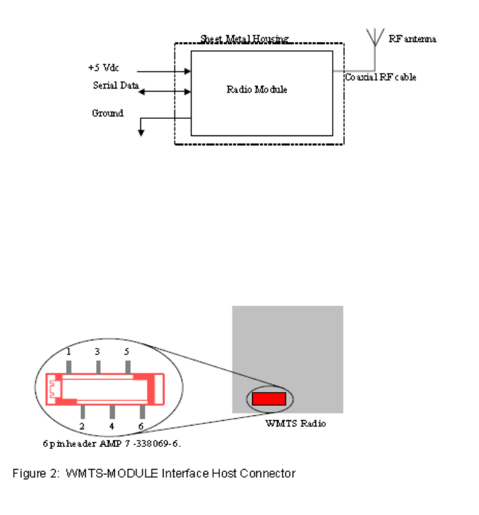
Figure 1: Module Block Diagram
2. Host Interface
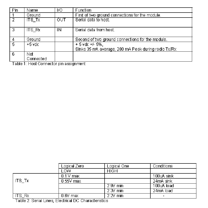
The Module interfaces to the host through a single I/O connector (Figure 2). Via this connector the host
supplies DC power, signal ground and modulating data to the radio Module. The communication between
the host device and the Module is a two wire asynchronous serial interface (Table 1).
Figure 2: Module Interface Host Connector
___________________________________________________________________
Application Note: WMTS-ITS2 The 1.4 GHz Radio Module
Confidential Page 3 of 5
3. Serial Connection
Serial Specification:
The interface to the Host is a serial communication link (Table 2):
• Flow Control: Tx, Rx; no hardware flow control
• Baud Rate: 115.2 kbaud;
• Parity: No parity bit
• Bits: 8 bits of data, plus 1 Start/Stop bits
• Logic Levels: TTL, 5 volt tolerant
Maximum User Data Rate:
The maximum user data rate that the radio supports is 12 kbits/second in each direction.
This maximum over the air date rate is fixed by design and cannot be modified by the
user.
4. RF Shielding
The host device does not need to provide additional shielding.

___________________________________________________________________
Application Note: WMTS-ITS2 The 1.4 GHz Radio Module
Confidential Page 4 of 5
5. Module Mounting Considerations
The Module is self-contained and can be mounted anywhere using the supplied threaded
pems nuts. Not special heat sinking considerations are required. There are not
orientation constraints.
6. RF Input/Output, Antenna
The Module is approved for use, with only the antennas specified by Philips and listed
here:
• Dipole Whip Philips Part Number M4842-61300
• Tri-Band Philips Part Number M3002-66493
• Dual-Band Philips Part Number M8100-66490
These antennas may not be replaced with antennas of a different type. However,
antennas of equivalent type with equal or lower gain to the listed antennas may be used.
The RF input and output of the Module is matched to 50 ohms. The Module has a
coaxial cable with which allows for the connection of the RF to the antenna by way of a
non-standard connector manufactured by JST. For the dipole whip, the connection is
JST-to-reversed-TNC adaptor made by Amphenol at the point where the antenna
connects.
7. RF Transmitter Specifications
The following table summarizes general transmitter specifications (Table 3).
1. Frequency ranges: Bands: 1395 - 1400 MHz and 1427 - 1432 MHz
2. RF Output Power 8 dBm +2/-1.5dB (4.5 mW to 10 mW, nominal 6.3 mW),
into Antenna load, calibrated into 50 Ohms UFL connector
port.
3. RF Output Power control a) Transmitter chain gain shall be calibrated at time of
manufacture (env temp 25+/-5deg.C).
b) Power control algorithm deployed to prevent excess
power and also includes temperature compensation.
4. Transceiver frequency accuracy during
normal operation <+60/-100KHz relative to channel frequency, includes
temperature compensation & aging effects.
5. Reference Frequency Accuracy 10ppm max over operating temperature
6. Modulation type GFSK, Gaussian Frequency Shift keying (1M40Q7D)
___________________________________________________________________
Application Note: WMTS-ITS2 The 1.4 GHz Radio Module
Confidential Page 5 of 5
8. Fault Conditions
Over / Under Voltage
The input voltage from the DC power source to the Module must remain between the
values specified in Table 1. Operating the radio Module from a voltage lower than 4.75 V
dc or higher than 5.25 V dc can cause the regulator to shut down ceasing operation of the
Module.
Excessive Signal Level on Serial Input
The data input signal levels must adhere to levels specified in Table 2. Driving the input
data line over 5V dc can cause damage to the Module input buffers, causing interruption
of data transfer.
Excessive Data Rate on Serial Input
The host serial communication data rate is fixed at 115.2 kbaud. Clocking data at
different baud rates will result in incorrect data transfer. The maximum host/user over
the RF link data rate is 12 kbps. Attempting to send data at a faster rate will result in data
buffer overrun and data loss.
9. Accompanying Documentation Products Incorporating the
Module
Products which incorporate this device will be labeled, “Contains FCC ID: PQC-WMTS-
ITS2,” and their accompanying documentation shall prominently display the following:
This device complies with Part 15 of the FCC Rules.
Operation is subject to the following two conditions:
(1) This device may not cause harmful interference, and
(2) This device must accept any interference received,
including interference that may cause undesired operation.
The documentation will also include the following text regarding frequency coordination:
Operation of this equipment requires the prior coordination with a frequency coordinator
designated by the FCC for the Wireless Medical Telemetry Service.