Philips Medical Systems North America WMTS-MODULE WMTS Radio Module User Manual Application Note
Philips Medical Systems North America Co. WMTS Radio Module Users Manual Application Note
Contents
- 1. Users Manual Application Note
- 2. USERS MANUAL
Users Manual Application Note

Page 1 of 6
Patient Monitoring
Quality & Regulatory Group
3000 Minuteman Road
Mailstop 0490
Andover, MA 01810
Tel: (978) 659-7383
Fax: (978) 685-5624
Application Note: WMTS-MODULE
Prepared by: Juan Brea
Last revised: 10-Mar-05
The following information is intended for Philips internal use only. It is a guide for the
incorporation of the WMTS-MODULE into Philips patient monitoring medical devices. Interested
Philips engineers should contact the Wireless ER Manager for additional information and referral
to specific design specialists.
This document is an internally controlled document under the Philips Quality System.
Philips Medical Systems
Page 2 of 6
1 Table of Contents
1 Table of Contents ..................................................................................................................... 2
2 Introduction............................................................................................................................... 3
3 Host Interface ........................................................................................................................... 3
4 Serial Connection ..................................................................................................................... 4
4.1 Serial Specification:...........................................................................................................4
4.2 Maximum User Data Rate:................................................................................................ 4
5 WMTS-MODULE RF Shielding. ............................................................................................... 4
6 WMTS-MODULE Mounting Considerations............................................................................. 5
7 RF Input/Output, Antenna ........................................................................................................5
7.1 RF Transmitter Specifications ........................................................................................... 5
8 Fault Conditions ....................................................................................................................... 5
8.1 Over/ Under Voltage ......................................................................................................... 5
8.2 Excessive Signal Level on Serial Input ............................................................................. 6
8.3 Excessive Data Rate on Serial Input ................................................................................ 6
9 Accompanying Documentation for products incorporating the WMTS-MODULE.................... 6
Page 3 of 6
2 Introduction
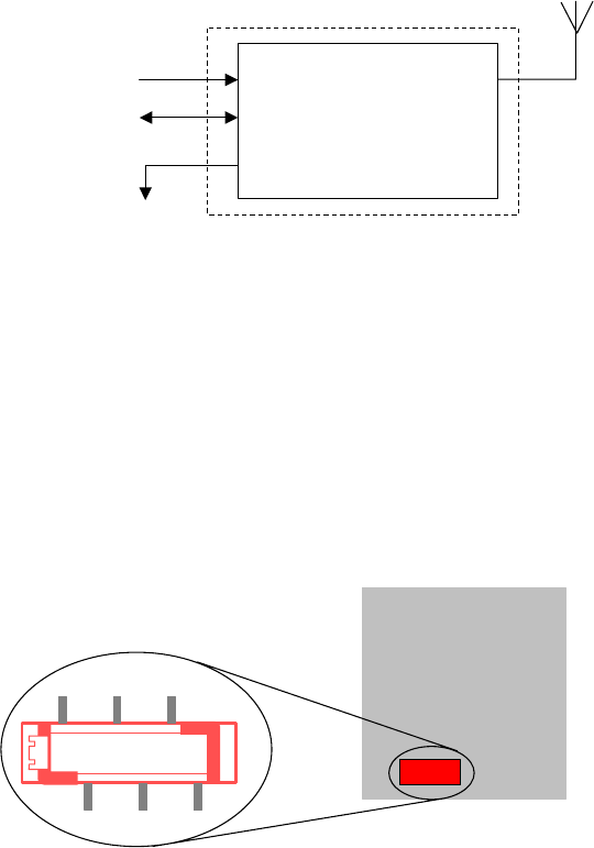
The WMTS-MODULE is a serial network adapter designed to be used with specialized medical
devices manufactured by Philips Medical Systems (Figure 1). It enables the host medical device
to wirelessly establish bi directional communication with other remote devices using the Philips’
WMTS infrastructure.
Figure 1: WMTS-MODULE Block Diagram
3 Host Interface
The WMTS radio module interfaces to the host though a single I/O connector (Figure 2). Via this
connector the host must supply DC power, signal ground and modulating data to the radio
module. The communication between the host device and the radio module is a two wire
asynchronous serial interface (Table 1).
Figure 2: WMTS-MODULE Interface Host Connector
53
1
642 WMTS Radio
6 pin header AMP 7 -338069-6.
+5 Vdc
Serial Data Radio Module
Sheet Metal Housin
g
Ground
Coaxial RF cable
RF antenna

Page 4 of 6
Pin Name I/O Function
1 Ground First of two ground connections for the module.
2 ITS_Tx OUT Serial data to host.
3 ITS_Rx IN Serial data from host.
4 Ground Second of two ground connections for the module.
5 +5 vdc + 5 vdc +/- 5%,
Sinks 35 mA average, 280 mA Peak during radio Tx/Rx
6 Not
Connected
Table 1: Host Connector pin assignment
4 Serial Connection
4.1 Serial Specification:
The interface to the Host is a serial communication link (Table 2):
Æ Flow Control: Tx, Rx; no hardware flow control
Æ Baud Rate: 115.2 kbaud;
Æ Parity: No parity bit
Æ Bits: 8 bits of data, plus 1 Start/Stop bits
Æ Logic Levels: TTL levels, 5 volt tolerant.
Logical Zero Logical One Conditions
LOW HIGH
0.1 V max 100uA sink
0.55V max 24mA sink
2.9V min 100uA load
ITS_Tx
2.3V min 24mA load
ITS_Rx 0.6V max 2.2V min -
Table 2: Serial Lines, Electrical DC Characteristics
4.2 Maximum User Data Rate:
The maximum user data rate that the radio supports is 12 kbits/second in each direction. This
maximum over the air data rate is fixed by design and cannot be modified by the user.
5 WMTS-MODULE RF Shielding.
The module contains all necessary RF shielding. The host device does not need to provide
additional shielding.

Page 5 of 6
6 WMTS-MODULE Mounting Considerations.
The module is self-contained and can be mounted anywhere using the supplied threaded pem
nuts. No special heat sinking considerations are required. There are no orientation constraints.
7 RF Input/Output, Antenna
The WMTS Radio Module is only approved for use with the antenna specified by Philips, part
number M4842-61300. This antenna cannot be replaced with an antenna of a different type. The
RF input and output of the WMTS-MODULE is matched to 50 ohms. A coaxial cable brings the
RF outside the metal enclosure. This cable uses a unique non standard connector manufactured
by JST (JST part number AYUI-1S-12676-221). The coaxial cable connects to a JST to reversed
TNC adapter made by Amphenol (Amphenol part number 031-6101) where the antenna plugs in.
The antenna is made by Radial to Philips’ specifications (Philips specifications number A-M4842-
61300-1, rev A).
7.1 RF Transmitter Specifications
The following table summarizes general transmitter specifications (Table 3). For complete details
(including details on the receiver section) refer to ES-M4840-90108:
1. Frequency ranges: Bands: 1395 - 1400 MHz and 1427 - 1432 MHz
2. RF Output Power 8 dBm +2/-3dB, 6.3 mW (3.2 mW to 10 mW), into Antenna
load. Calibrated into 50 ohms.
3. RF Output Power control a) Transmitter chain gain shall be calibrated at time of
manufacture (env temp 25+/-5deg.C).
b) Over power algorithm deployed to prevent excess power
and also includes temperature compensation.
4. Transceiver frequency accuracy +/-15KHz relative to channel frequency, includes
temperature compensation & aging effects.
5. Reference Frequency Calibration <4ppm
6. Modulation type FSK with Root Raised Cosine filtering (1M60Q7D)
Table 3: WMTS Radio Module, Transmitter Specifications
8 Fault Conditions
8.1 Over/ Under Voltage
The input voltage from the DC power source to the module must remain between the values
specified in Table 1. Operating the radio module from a voltage lower source lower than 4.75VDc
or higher that 5.25 vdc can cause the regulator section to shut down ceasing operation of the
radio module.
Page 6 of 6
8.2 Excessive Signal Level on Serial Input
The data input signal levels must be observed as specified in Table 2. Driving the input data line
over 5 vdc can cause damage to the radio module input buffers, causing interruption of data
transfer.
8.3 Excessive Data Rate on Serial Input
The host serial communication data rate is fixed at 115.2 kbaud. Clocking data at different baud
rates will result in incorrect data transfer. The maximum host/user over the RF link data rate is 12
kbps. Attempting to send data at a faster rate will result in data buffer overrun and data loss.
9 Accompanying Documentation for products incorporating the
WMTS-MODULE
Products which incorporate this device will be labeled “Contains PQC-WMTS-MODULE”, and
their accompanying documentation will also advise the user concerning frequency coordination
(47 CFR 95.1109), as follows:
“Operation of this equipment requires the prior coordination with a frequency coordinator
designated by the FCC for the Wireless Medical Telemetry Service.”