Philips MNT174 DU AG 0018 21 Rev D User Manual Product Brochure Intelli Vue MP40/MP50 Mounting Solution 39559a69b3ec4df6a591a77c015f6a75
MNT174 Installation Note for AG-0018-21 HCMNT174%2DInstallation%2DNote%2Dfor%2DAG%2D0018%2D21 IntelliVue MP20/MP30 GCX Variable Height Wall Mount Mounting solutionMNT174
MNT174 Installation Note for AG-0018-22 HCMNT174%2DInstallation%2DNote%2Dfor%2DAG%2D0018%2D22 IntelliVue MP20/MP30 GCX Variable Height Wall Mount Mounting solutionMNT174
MNT138 Installation Note for AG-0018-21 HCMNT138%2DInstallation%2DNote%2Dfor%2DAG%2D0018%2D21 IntelliVue MP40/MP50 GCX Variable Height Wall Mount Mounting solutionMNT138
MNT138 Installation Note for AG-0018-22 HCMNT138%2DInstallation%2DNote%2Dfor%2DAG%2D0018%2D22 IntelliVue MP40/MP50 GCX Variable Height Wall Mount Mounting solutionMNT138
MNT98 Installation Note for AG-0018-21 HCMNT98%2DInstallation%2DNote%2Dfor%2DAG%2D0018%2D21 IntelliVue MP60/MP70 GCX Variable Height Wall Mount Mounting solutionMNT98
User Manual: Philips MNT174 Product Brochure Philips IntelliVue MP40/MP50 Mounting solution Philips - IntelliVue MP20/MP30 GCX Variable Height Wall MountMNT174
Open the PDF directly: View PDF ![]() .
.
Page Count: 5
DU-AG-0018-21 Rev D 8/21/07 GCX Corp Page 1 of 5
Installation Guide
Philips MP20/30/40/50/60/70 IntelliVue M-Series Arm Wall Mount Kit
The purpose of this guide is to:
1. Describe attachment of Table Top Mount to Mounting Adapter.
2. Describe attachment of Down Post to Arm.
3. Describe mounting of Arm in Wall Channel.
4. Describe attachment of Flexible Module Server (FMS) to Down Post.
5. Describe special mounting procedure for MP20/30 monitor.
6. Describe operation and adjustment of M-Series Arm.
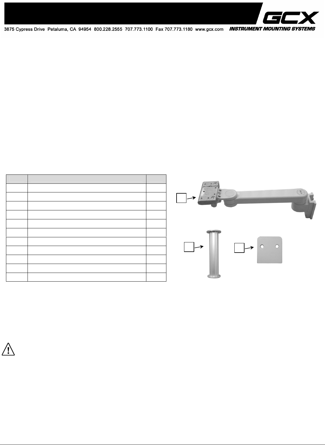
Parts Reference
The following parts and hardware are included for this installation procedure (see photos for parts; hardware not shown).
Tools Required: Phillips screwdriver (not provided), 5/32'' and 1/8'' hex wrenches (provided).
Caution - Before mounting the Arm:
1. Verify that the Channel has been installed and approved in accordance with the Channel Installation guides.
2. Ensure that the weight of the device being mounted does not exceed the load rating of your M-Series Arm. Check the
"Max Load" rating label located on top of the arm at the Slide pivot point. It is not recommended that this arm be used
for weights outside of this range.
3. If assistance is needed regarding an application, please contact a GCX product specialist at (800) 228-2555.
Item # Description Qty
1 M-Series Arm with Mounting Adapter 1
2 6'' Down Post Kit 1
3 #10-32 x 3/8'' Socket Head Cap Screw 3
4 M6 x 8mm Flat Head Machine Screw (FHMS) 2
5 M6 x 12mm FHMS 1
6 Adjustable Stop 1
7 5/32'' Hex Wrench 1
8 1/8'' Hex Wrench 1
9 Channel Cover, 16'' 1
*10 Spacer, MP20/30 1
*11 M6 x 16mm Pan Head Machine Screw (PHMS) 2
*See "MP20/30 non-Table Top Mount" at bottom of page 3 for use of
these parts.
1
210
DU-AG-0018-21 Rev D 8/21/07 GCX Corp Page 2 of 5
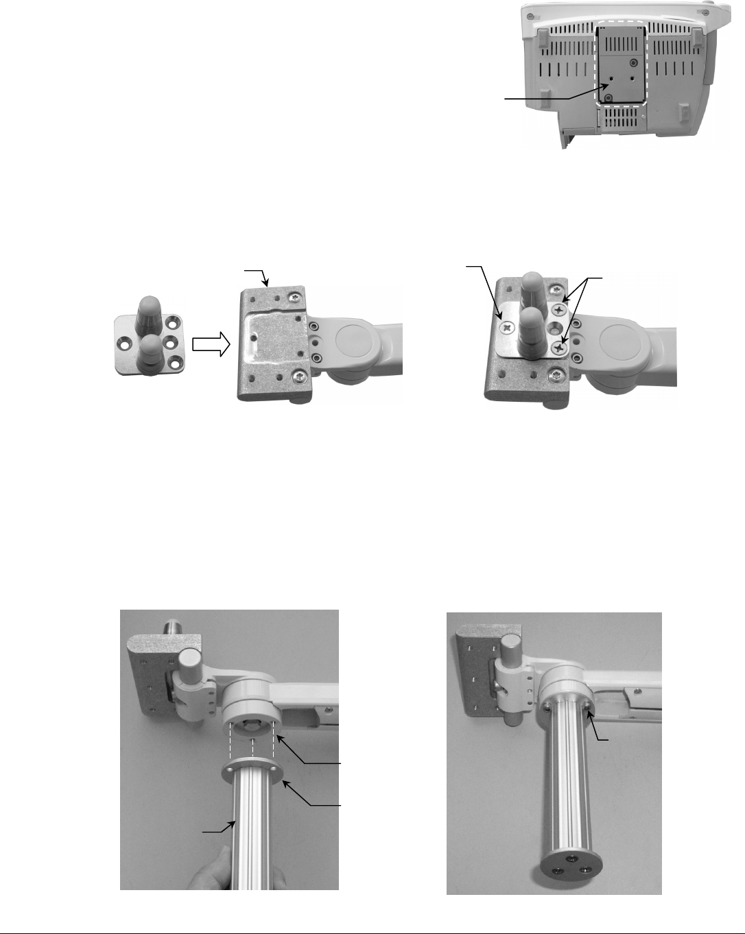
Attaching the Philips Table Top Mount to the Mounting Adapter
Installation Note: Do not attach the Table Top Mount to the Arm/Mounting
Adapter if you will be mounting an MP20/30 monitor equipped with the
mounting interface shown in photo (right). See "Mounting the Monitor on the
Arm" (page 3) for instructions specific to this type of mounting plate.
1. Fasten the Philips-supplied Table Top Mount to the Mounting Adapter on the M-Series Arm with one (1) M6 x 12mm
FHMS and two (2) M6 x 8mm FHMS (see below).
Attaching the Down Post to the Arm
Installation Note: The Down Post is used for mounting the Flexible Module Server (FMS). Skip this procedure if your
IntelliVue monitoring system does not require a Down Post or FMS.
1. Align the three (3) mounting holes in the Lower Post Disc with the three (3) threaded holes in the Swivel Cup.
2. Using the 5/32'' hex wrench, fasten Post to Swivel Cup with three (3) #10-32 x 3/8'' SHCS.
#10-32 x 3/8'' SHCS (3)
6'' Down Post
Lower Post Disc
Swivel Cup
M6 X 12mm FHMS (1)
M6 X 8mm FHMS (2)
Mounting Adapte
r
Table Top Mount
Do Not Attach Table Top Mount if MP20/30
Monitor is Equipped with This Mounting Interface
DU-AG-0018-21 Rev D 8/21/07 GCX Corp Page 3 of 5
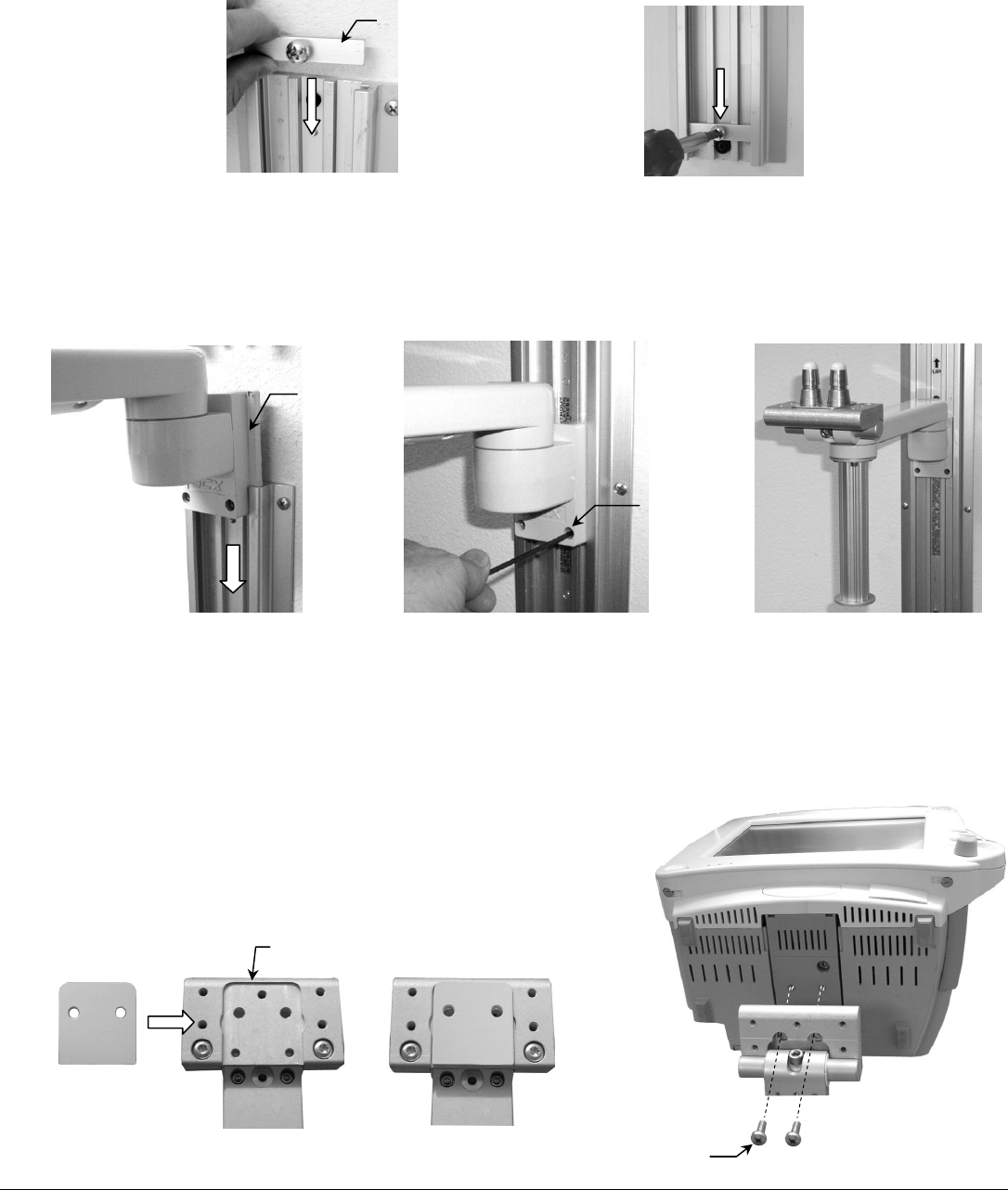
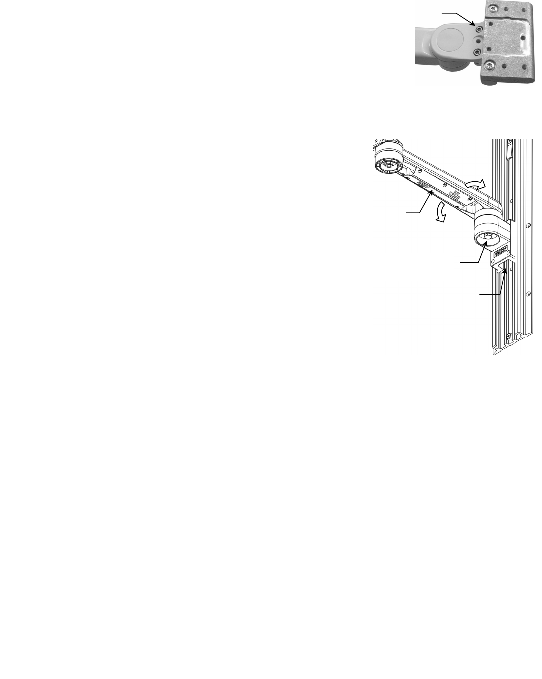
Mounting the M-Series Arm in the Wall Channel
1. Insert the Adjustable Stop in the top opening of the wall channel and slide it to the bottom of the channel. Secure the
Adjustable Stop in the channel by tightening the screw in the center of the Stop.
2. While supporting the bottom of the Arm, guide the Slide (at rear of Arm) into the top of the wall channel. Slide the Arm
to the desired position in the channel and tighten two (2) set screws (bottom of the Slide) using the 1/8'' key. The M-
Series Arm should be securely mounted as shown below right.
Mounting the Monitor on the Arm
Table Top Mount
Mount the monitor in accordance with the Philips Table Top Mount instruction sheet.
MP20/30 non-Table Top Mount
1. Fit Spacer into recessed area on top of Mounting Adapter (below).
Ensure Spacer remains between Mounting Adapter and monitor.
2. Insert two (2) M6 x 16mm PHMS through bottom of Mounting Adapter
and thread into mounting holes in bottom of monitor (right).
A
djustable Stop
Slide
Set Screws (2)
Mounting Adapter
Spacer
M6 x 16 mm PHMS (2)
DU-AG-0018-21 Rev D 8/21/07 GCX Corp Page 4 of 5
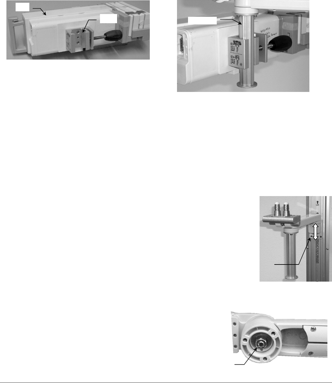
Mounting the Flexible Module Server (FMS) on the Down Post
Installation Note: This procedure is not applicable unless Down Post has been installed.
1. Mount the FMS on the Down Post by placing the Clamp around the Down Post and tightening the knob.
Installing the Wall Channel Cover
Install the Wall Channel Cover in accordance with the Channel Cover Installation Guide (DU-UT-0001-20).
M-Series Arm Operation and Adjustment
Positioning Arm in Channel
WARNING: Do not attempt to remove the Arm from the Channel while an instrument is mounted.
1. While *supporting the weight of the mounted instrument, loosen the two (2)
socket head set screws (SHSS) in the Slide. A 1/8'' hex key is provided for this
task.
2. Push up or pull down at the end of the arm nearest the Slide. Tighten the set
screws to secure the Arm in the Channel
* It may be necessary to dismount the instrument before adjusting the Arm in the
Channel.
Swiveling the Mounted Instrument and Adjusting Swivel Tension
1. To swivel the mounted instrument simply push or pull the corners of the
instrument.
2. To adjust swivel tension, tighten or loosen the Swivel Tension Nut using
a 1/2'' [13 mm] socket wrench or nut driver.
Socket Head Set Screws (2)
Down Post
Swivel Tension Nut
FMS
Clamp
DU-AG-0018-21 Rev D 8/21/07 GCX Corp Page 5 of 5
Tilt Tension Screws (2)
Pivot Tension Bolt
Flexible Cable Covers
Pass-through Slide
Tilting the Mounted Instrument
1. To tilt the instrument, grasp the top and bottom of the instrument
and tilt it to the desired angle.
2. To adjust tilt tension, equally tighten or loosen the two (2) Tilt
Tension Adjustment screws using the 5/32'' hex wrench provided.
Pivoting the Arm and Adjusting Pivot Tension
1. To pivot the Arm at the Slide, simply push on the side of the
Arm or mounted instrument.
2. To adjust pivot tension, loosen or tighten the Pivot Tension
Bolt using a 1/2" [13 mm] socket driver.
Cable Management
Two cable management features allow convenient placement
and flow of cables:
1. An open cavity beneath the arm (with flexible cable covers)
allows management of cables between the front and rear of
the arm.
2. A “pass-through” channel at the rear of the slide allows
cables to pass behind the arm within the Channel.
Installation Note: If cable connectors are too large to fit
through the pass-through, try placing the cables in the "pass-
through" before installing the arm in the Channel. Contact
GCX for optional Channel Covers available to further manage
the flow of cables in the Channel.
Cleaning the Mounting System
1. The mounting assembly may be cleaned with most mild, non-abrasive solutions commonly used in the hospital
environment (e.g. diluted bleach, ammonia, or alcohol solutions).
2. The surface finish will be permanently damaged by strong chemicals and solvents such as acetone and
trichloroethylene.
3. Do not use steel wool or other abrasive material to clean the mounting assembly.
4. Damage caused by the use of unapproved substances or processes will not be covered by warranty. We recommend
testing of any cleaning solution on a small area of the mounting assembly that is not visible to verify compatibility.
5. Never submerge or allow liquids to enter the mounting assembly. Wipe any cleaning agents off of the mounting
assembly immediately using a water-dampened cloth. Dry the mounting assembly thoroughly after cleaning.
CAUTION: GCX makes no claims regarding the efficacy of the listed chemicals or processes as a means for controlling
infection. Consult your hospital’s infection control officer or epidemiologist. To clean or sterilize mounted instruments or
accessory equipment, refer to the specific instructions delivered with those products.
