Phoenix Contact and KG ADIOMUX Wireless Mux Module User Manual DB EN ILB BT ADIO MUX
Phoenix Contact GmbH & Co. KG Wireless Mux Module DB EN ILB BT ADIO MUX
UserManual.pdf
Preliminary Preliminary Preliminary Preliminary
1Description
Wireless-MUX module with 16digital inputs,
16 digital outputs, 2 analog inputs, and 2 analog
outputs
ILB BT ADIO MUX...
© PHOENIX CONTACT
Data sheet
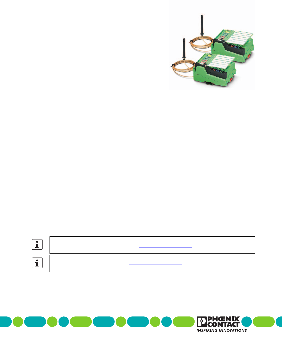
The set consists of two modules that form a fixed pair as the
master and slave.
The Wireless-MUX module transmits 16digital and
2analog signals bidirectionally by means of wireless
communication. It therefore replaces a 40-wire signal cable.
The wireless solution has been developed specifically for
use under industrial conditions. It is reliable, robust, and
easy to handle.
Features
– Easy startup, plug and play
– Bar graph for wireless diagnostics
– Range of up to 400m outdoors
– 16 digital inputs
– 16 digital outputs
– Diagnostic and status indicators
– 2 analog single-ended signal inputs for the connection
of either voltage or current signals
– 2 analog single-ended signal outputs for the connection
of either voltage or current signals
Please note the maximum permissible transmission power for the country of use.
For the latest country registrations, please visit phoenixcontact.net/products.
Make sure you always use the latest documentation.
It can be downloaded from the product at phoenixcontact.net/products.
7173_en_11 2017-01-25

ILB BT ADIO MUX...
Preliminary Preliminary Preliminary Preliminary
7173_en_11 PHOENIX CONTACT 2 / 18
2Table of contents
1 Description .............................................................................................................................. 1
2 Table of contents..................................................................................................................... 2
3 Ordering data .......................................................................................................................... 3
4 Technical data ......................................................................................................................... 5
5 Safety regulations and installation notes.................................................................................. 9
5.1 Intended use ...................................................................................................................... 9
5.2 Installation notes ................................................................................................................. 9
5.3 FCC approval ................................................................................................................... 10
5.4 Approval for Japan............................................................................................................. 10
6 Local diagnostic and status indicators................................................................................... 11
7 Connect supply, actuators, and sensors................................................................................ 11
7.1 Terminal point assignment ................................................................................................... 12
8 Basic circuit diagram ............................................................................................................. 13
9 Connection example.............................................................................................................. 13
10 Assignment of terminal points to the remote station .............................................................. 14
11 Antennas ............................................................................................................................... 15
11.1 Omnidirectional antennas .................................................................................................... 15
11.2 Range............................................................................................................................. 18
11.3 Typical combinations of antennas and adapter cables ................................................................ 18

ILB BT ADIO MUX...
Preliminary Preliminary Preliminary Preliminary
7173_en_11 PHOENIX CONTACT 3 / 18
Description Ty p e Order No. Pcs./Pkt.
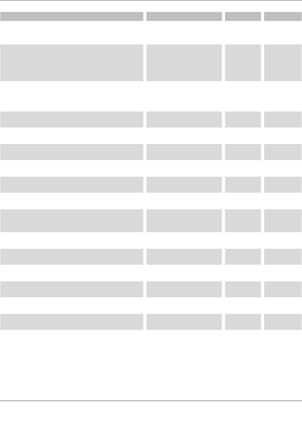
Wireless-MUX set, two modules with 16 digital inputs and
outputs and 2 analog inputs and outputs (0...20mA,
0...10V) each, incl. omnidirectional antennas with 1.5m
cable
ILB BT ADIO MUX-OMNI 2884208 1
Wireless-MUX set, two modules with 16 digital inputs and
outputs and 2 analog inputs and outputs (0 - 20mA,
0 - 10V) each, without antennas
ILB BT ADIO MUX 2702875 1
3Ordering data
Accessories Ty p e Order No. Pcs./Pkt.
Inline shield connector IB IL SCN 6-SHIELD-TWIN 2740245 5
Connector, colored, for Inline power and segment terminal
blocks
IB IL SCN-PWR IN-CP 2727637 10
Connector, for digital 1, 2 or 8-channel Inline terminals IB IL SCN-8 2726337 10
Labeling field, width: 12.2 mm IB IL FIELD 2 2727501 10
Insert strip, Sheet, white, unlabeled, can be labeled with:
Office printing systems, CMS-P1-PLOTTER:Laser
printer, Mounting type: Insert, Lettering field: 62 x 10 mm
ESL 62X10 0809492 1
Zack Marker strip, flat, white,
for terminal block width: 6.2 mm
ZBF 6:SO/CMS 0808778 1
Flat zack marker sheet, white,
for terminal block width: 6.2 mm
ZBFM 6:SO/CMS 0803650 1
Flat zack marker sheet, Sheet, white, unlabeled, can be
labeled with: CMS-P1-PLOTTER, PLOTMARK, Mounting
type: Snap into flat marker groove, for terminal block
width: 6.2 mm, Lettering field: 5 x 5.5 mm
ZBFM 6/WH:UNBEDRUCKT 0803618 10
Quick mounting end clamp for NS 35/7,5 DIN rail or NS 35/
15 DIN rail, with marking option, with parking option for
FBS...5, FBS...6, KSS 5, KSS 6, width: 5.15 mm, color:
gray End clamp, Width:5.15 mm, Height:35 mm,
Length:48.5 mm, Color:gray
CLIPFIX 35-5 3022276 50
Omnidirectional antenna, 2.4 GHz, 2 dBi, linear vertical,
1.5 m cable, RSMA (male), IP65, 50 Ω impedance
RAD-ISM-2400-ANT-OMNI-2-
1-RSMA
2701362 1
Omnidirectional antenna with protection against
vandalism, 2.4 GHz, 3 dBi gain, IP55 degree of protection,
1.5 m cable length, RSMA connection (male), h/v 360°/
85° apex angle.
Appropriate mounting material is available for wall
mounting.
RAD-ISM-2400-ANT-VAN-3-
0-RSMA
2701358 1
Omnidirectional antenna, 2.4 GHz, 6 dBi, linear vertical,
opening angle 360°/30°, N (female), IP67, incl. mounting
bracket and mast clips for 45mm - 100mmdiameter,
stainless steel, ATEX &IECEx approval, salt water
resistant
RAD-ISM-2400-ANT-OMNI-6-
0
2885919 1
ILB BT ADIO MUX...
Preliminary Preliminary Preliminary Preliminary
7173_en_11 PHOENIX CONTACT 4 / 18
Omnidirectional antenna, 2.4 GHz, 6 dBi, linear vertical,
opening angle h/v 360°/20°, N (female), IP65, salt water
resistant
RAD-2400-ANT-OMNI-6-0-
SW
2903219 1
Dual band omnidirectional antenna with protection against
vandalism; IP68 protection; frequency band/gain:
2.4 GHz/up to 6 dBi, 5 GHz/up to 8 dBi; EN 50155;
temperature range: -40°C to +80°C; N (f) connection;
1 m long adapter cable, N (m) - SMA (m) connection.
RAD-ISM-2459-ANT-FOOD-
6-0
2692526 1
Panel antenna, 2.4/5GHz, 9dBi, linear vertical,
N (female), IP67, incl. mounting bracket and mast clips for
25mm - 85mmdiameter, stainless steel, ATEX &IECEx
approval
ANT-DIR-2459-01 2701186 1
Adapter cable as control cabinet feed-through, N (female)
-> RSMA (male), impedance: 50 Ω, length: 0.5 m
RAD-PIG-EF316-N-RSMA 2701402 1
Antenna cable, 0.5 m in length; N (male) -> RSMA (male),
impedance 50 ohms
RAD-PIG-RSMA/N-0.5 2903263 1
Antenna cable, 1 m in length; N (male) -> RSMA (male),
impedance 50 ohms
RAD-PIG-RSMA/N-1 2903264 1
Antenna cable, 2 m in length; N (male) -> RSMA (male),
impedance 50 ohms
RAD-PIG-RSMA/N-2 2903265 1
Antenna cable, 3 m in length; N (male) -> RSMA (male),
impedance 50 ohms
RAD-PIG-RSMA/N-3 2903266 1
Antenna cable, 5 m in length; N (male) -> RSMA (male),
impedance 50 ohms
RAD-PIG-RSMA/N-5 2702140 1
Attachment plug with Lambda/4 technology as surge
protection for coaxial signal interfaces.
Connection: N connectors socket-socket
CN-LAMBDA/4-5.9-BB 2838490 1
Adapter, N (female) -> N (female);
insertion attenuation < 0.3 dB at 2.4 GHz
RAD-ADP-N/F-N/F 2867843 1
Adapter, RSMA (male) -> RSMA (female) 90°;
Insertion loss < 0.3 dB at 2.4GHz
RAD-ADP-RSMA/M-RSMA/F-
90
2904790 1
Antenna cable, 3 m in length, N (male) -> N (male),
50 Ω impedance
RAD-CAB-EF393- 3M 2867649 1
Antenna cable, 5 m in length, N (male) -> N (male),
50 Ω impedance
RAD-CAB-EF393- 5M 2867652 1
Antenna cable, 10 m in length, N (male) -> N (male),
50 Ω impedance
RAD-CAB-EF393-10M 2867665 1
Antenna extension cable, 15 m in length,
N (male) -> N (male), 50 Ω impedance
RAD-CAB-EF393-15M 2885634 1
Accessories Ty p e Order No. Pcs./Pkt.
ILB BT ADIO MUX...
Preliminary Preliminary Preliminary Preliminary
7173_en_11 PHOENIX CONTACT 5 / 18
Control box for robust construction of wireless systems for
industrial applications, IP66, 25 x 18 x 13cm,
polycarbonate material, gray, drilled, incl. DIN rail, plugs,
and screw connections, without devices
FL RUGGED BOX 2701204 1
Set for mast mounting of the FL RUGGED BOX housing,
incl. screw clamps for masts up to 89 mm
FL RUGGED BOX POLE SET 2701205 1
Vulcanizing sealing tape for external protection of
adapters, cable connections, etc. against the effects of
weather, roll length: 3 m
RAD-TAPE-SV-19-3 2903182 1
Accessories Ty p e Order No. Pcs./Pkt.
4 Technical data
Dimensions
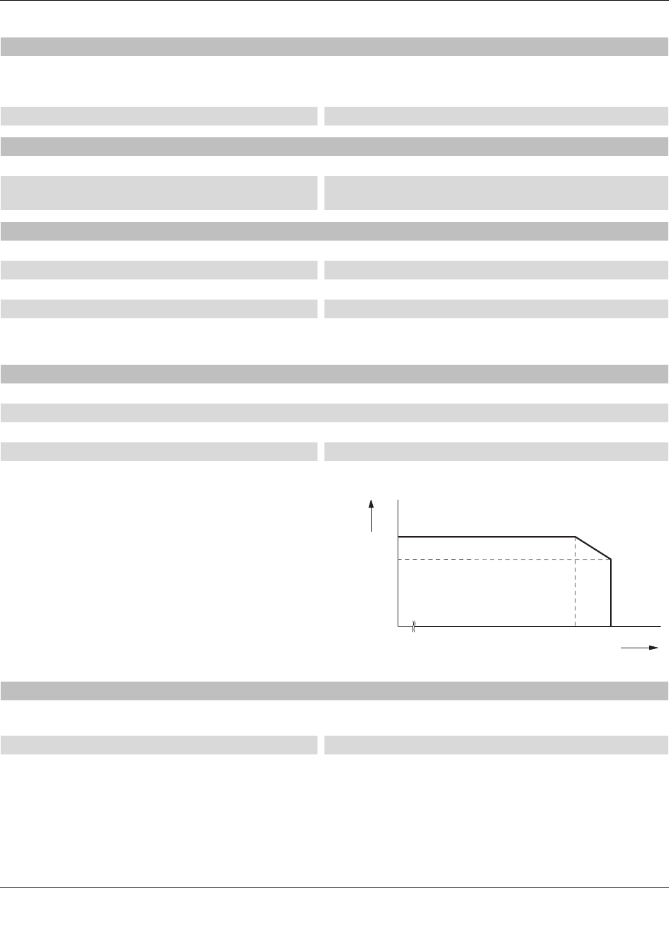
Dimensions W/H/D 95 mm / 123.4 mm / 57 mm
95
123,4
58,5
General data
Overvoltage category II
Degree of protection IP20
Protection class III
Degree of pollution 2
Housing material PA 6.6-FR
Weight 274 g
Vibration resistance in acc. with EN60068-2-6/
IEC60068-2-6
5g
Shock in acc. with EN60068-2-27/IEC60068-2-27 25g, 11 ms period, half-sine shock pulse
MTTF (mean time to failure) Telcordia standard, 25°C
temperature, 21% operating cycle (5 days a week, 8 hours
a day)
1458 Years
MTTF (mean time to failure) Telcordia standard, 40°C
temperature, 34.25% operating cycle (5 days a week, 12
hours a day)
557 Years
MTTF (mean time to failure) Telcordia standard,
temperature 40 °C, operating cycle 100 % (7 days a week,
24 hours a day)
219 Years

ILB BT ADIO MUX...
Preliminary Preliminary Preliminary Preliminary
7173_en_11 PHOENIX CONTACT 6 / 18
Power supply for module electronics
Supply voltage 24 V DC
Supply voltage range 19.2 V DC ... 30.5 V DC (via power connector)
Current consumption 60 mA (Communications power at 24VDC, 25°C)
25 mA (Actuator supply, +load current Digital OUT (8A))
Protective circuit Polarity protection, surge protection
Connection method Inline connector
Wireless interface
Frequency range 2.402 GHz ... 2.48 GHz (ISM bandwidth)
Channel distance 2 MHz
No. of channels 40
Modulation type GFSK (Gaussian Frequency Shift Keying)
Transmission power 5 dBm
Receiver sensitivity -95 dBm
Antenna connection method RSMA (female)
Digital inputs
Number of inputs 16
Connection method Spring-cage connection
Connection method 1-wire
Input voltage range "0" signal < 5 V
Input voltage range "1" signal > 15 V
Common potentials Ground
Nominal input voltage UIN 24 V DC
Typical input current per channel 2.3 mA
Permissible conductor length to the sensor 100 m
Use of AC sensors AC sensors in the voltage range < UIN are limited in application
(according to the input design)
Digital outputs
Number of outputs 16
Connection method Spring-cage connection
Connection method 1-wire
Nominal output voltage 24 V DC
Voltage difference with nominal current ≤ 1 V
Protective circuit Short-circuit protection, overload protection, protected against
reverse voltages
Maximum output current per channel 500 mA
Output current 8 A
Nominal load, ohmic 12 W (48 Ω)
Nominal load, lamp 12 W
Nominal load, inductive 12 VA (1.2 H, 50 Ω)
Operating frequency with inductive nominal load 0.5 Hz
Behavior with overload Auto restart

ILB BT ADIO MUX...
Preliminary Preliminary Preliminary Preliminary
7173_en_11 PHOENIX CONTACT 7 / 18
Behavior with inductive overload Output can be destroyed
Reverse voltage resistance to short pulses Reverse voltage proof
Resistance to permanent reverse voltage ≤ 2 A
Behavior at voltage switch-off The output follows the power supply without delay
Overcurrent shut-down ≥ 0.7 A
Output current when switched off ≤ 10 µA (When not loaded, a voltage can be measured even at
an output that is not set.)
Digital outputs
Analog inputs
Number of inputs 2
Description of the input Single ended
Measured value resolution 12 bits
Current input signal 0 mA ... 20 mA
Input resistance current input 110 Ω (Shunt)
Voltage input signal 0 V ... 10 V
Input resistance of voltage input > 150 kΩ
Type of protection Suppressor diodes in the analog inputs, current limitation via
internal protective circuit
Analog outputs
Number of outputs 2
DAC resolution 12 Bit
Current output signal 0 mA ... 20 mA
Load/output load current output ≤ 500 Ω
Voltage output signal 0 V ... 10 V
Load/output load voltage output ≥ 2 kΩ
Type of protection Transient protection
Te s t voltage
Test voltage 500 V AC (50 Hz, 1 min.)
Ambient conditions
Ambient temperature (operation) -25 °C ... 60 °C
Ambient temperature (storage/transport) -25 °C ... 85 °C
Permissible humidity (operation) 95 % (non-condensing)
Permissible humidity (storage/transport) 95 %
Air pressure (operation) 795 hPa ... 1080 hPa (up to 2000 m above mean sea level)
Air pressure (storage/transport) 66 kPa ... 108 kPa (up to 3500 m above mean sea level)
ILB BT ADIO MUX...
Preliminary Preliminary Preliminary Preliminary
7173_en_11 PHOENIX CONTACT 8 / 18
Certification
Conformance FCC Directive, Part 15.247
ISC Directive RSS 210
EAC
UL, USA/Canada UL 508 Listed
Emitted interference in acc. with EN 61000-6-4
Emitted radio interference in acc. with EN 55011 EN 55011 class A industrial area of application
Interference emission EN 61000-6-4
Conformance
Effective use of the radio spectrum according to EN 300328
Noise immunity according to EN 61000-6-2
Noise emission according to EN 61000-6-4
Health according to EN 50385
Electrical safety according to EN 60950-1
Limitation of simultaneity, derating
No limitation of simultaneity
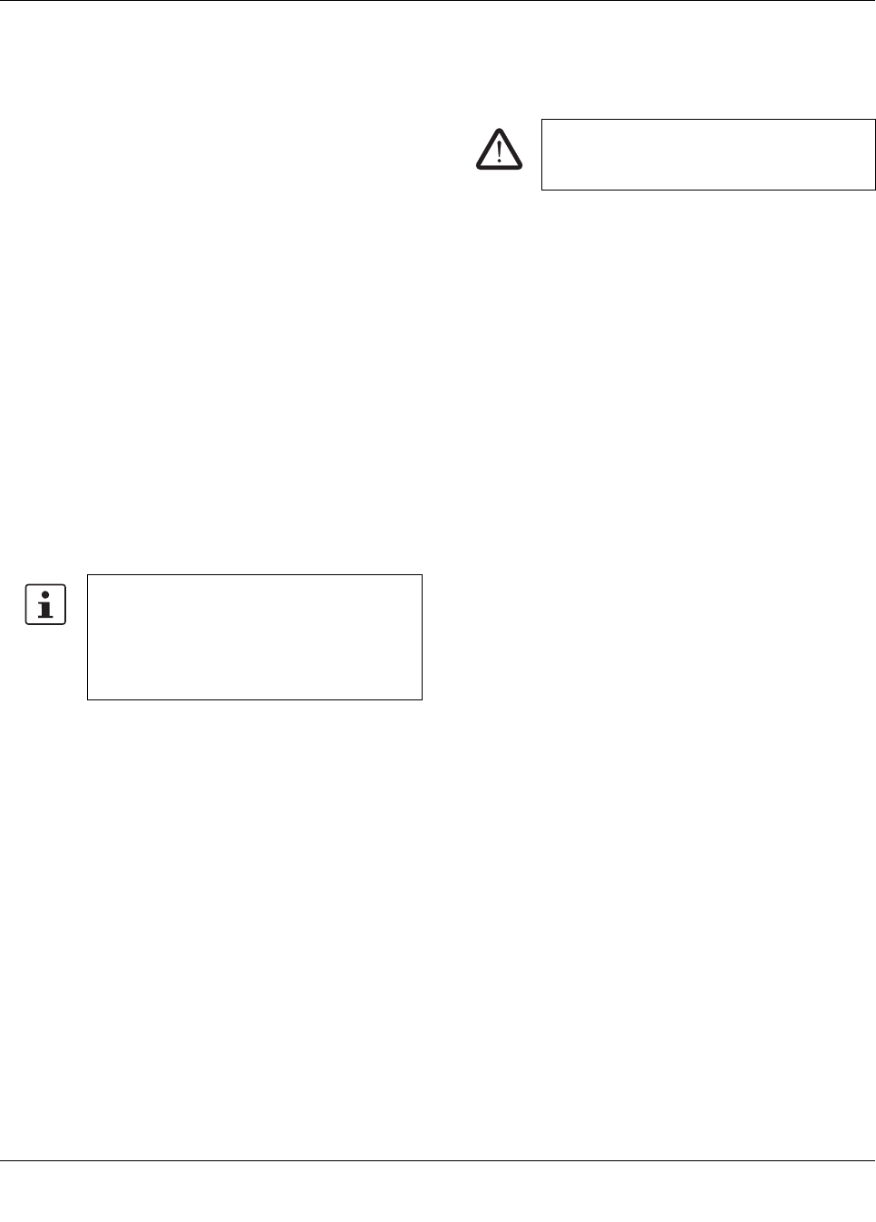
Derating of outputs
Ambient temperature TATotal current Itot
-25°C...+50°C 8 A
+50°C...+60°C 8A - ((TA - 50°C) x 0.2A/°C)
10
8
4
2
0
I [A]
TOT
T [°C]
A
-25 10 20 30 40 50 60 70
6
Tolerance of analog inputs and outputs
An analog channel consists of an input and output. The tolerance values refer to the measuring range final value. They
include all tolerances of the input and output.
Precision 0.3%,typical; 0.6%,maximum
Temperature response 220ppm/°C
ILB BT ADIO MUX...
Preliminary Preliminary Preliminary Preliminary
7173_en_11 PHOENIX CONTACT 9 / 18
5 Safety regulations and installation notes
5.1 Intended use
The devices are intended for application in industrial
environments.
The wireless system is ClassA equipment and may cause
radio interference in residential areas. In this case, the
operator may be required to implement appropriate
measures and to pay the costs incurred as a result.
This device complies with R&TTE device class 1, with the
following restrictions on use according to ERC
recommendation 70-03:
Please note that, in combination with antennas, the
maximum permissible transmission power may be
exceeded. In this case, set the transmission power via the
software.
5.2 Installation notes
•Installation, operation, and maintenance may only be
carried out by qualified electricians. Follow the
installation instructions as described.
•When installing and operating the device, the
applicable regulations and safety directives (including
national safety directives), as well as general technical
regulations, must be observed. The technical data is
provided in the package slip and on the certificates
(conformity assessment, additional approvals where
applicable).
•The device must not be opened or modified. Do not
repair the device yourself, replace it with an equivalent
device. Repairs may only be carried out by the
manufacturer. The manufacturer is not liable for
damage resulting from violation.
•The IP20 protection (IEC 60529/EN 60529) of the
device is intended for use in a clean and dry
environment. The device must not be subject to
mechanical strain and/or thermal loads, which exceed
the limits described.
•The device complies with the EMC regulations for
industrial areas (EMC classA). When using the device
in residential areas, it may cause radio interference.
•The device is only intended for operation in the control
cabinet and with SELV according to IEC 60950/
EN 60950/VDE 0805. The device may only be
connected to devices, which meet the requirements of
EN 60950.
•Operation of the wireless system is only permitted when
using accessories available from Phoenix Contact. The
use of any other components can lead to the withdrawal
of the operating license.
Norway: The device must not be operated within
20km of Ny Ålesund town center.
Turkey: The device must only be operated with
PhoenixContact antennas - according to the
regulations in Gazette "Short Range Radio
Devices (SRD) Regulations" no. 26464 dated
16/03/2007.
Install the wireless module at least 1m away
from other devices using the 2.4GHz
frequency band (e.g., WLAN, Bluetooth,
microwave ovens). Otherwise, both the
transmission quality and data transmission
rate will be reduced.
WARNING:
Observe the following safety notes when
using the device.
ILB BT ADIO MUX...
Preliminary Preliminary Preliminary Preliminary
7173_en_11 PHOENIX CONTACT 10 / 18
5.3 FCC approval
This device complies with Part 15 of the FCC rules and
Industry Canada's licence-exempt RSSs. Operation is
subject to the following two conditions:
(1) This device may not cause harmful interference.
(2) This device must accept any interference received,
including interference that may cause undesired operation.
Any changes or modifications not explicitly approved by
PhoenixContact could cause the device to cease to comply
with FCC rules Part15, and thus void the user's authority to
operate the equipment.
Radio frequency exposure:
The device contains a radio transmitter and receiver. During
communication the device receives and transmits radio
frequency (RF) electromagnetic fields (microwaves) in the
frequency range of 2400MHz to 2483.5MHz.
RF Exposure Statement:
This equipment should be installed and operated with a
minimum distance of 20cm between the radiator and your
body.
This transmitter must not be co-located or operating in
conjunction with any other antenna or transmitter.
Changes or modifications not expressly approved by the
party responsible for compliance could void the user's
authority to operate the equipment.
5.4 Approval for Japan
NOTE: Interference
This equipment has been tested and found to
comply with the limits for a Class A digital
device, pursuant to part 15 of the FCC rules.
These limits are designed to provide
reasonable protection against harmful
interference when the equipment is operated
in a commercial environment. This equipment
generates, uses and can radiate radio
frequency energy and, if not installed and
used in accordance with the instruction
manual, may cause harmful interference to
radio communications. Operation of this
equipment in a residential area is likely to
cause harmful interference, in which case, the
user will be required to correct the
interference at his own expense.
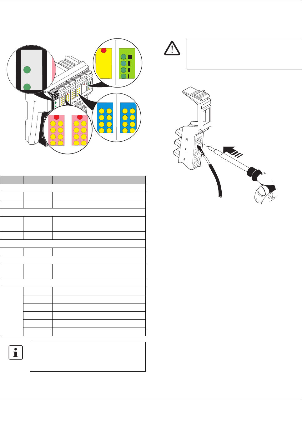
Japanese Radio Law and Japanese Telecommunications Business Law Compliance
The device is granted pursuant to the Japanese Radio Law ( ).
This device should not be modified (otherwise the granted designation number will
become invalid).
Contains:
XXX-XXXXXX
ILB BT ADIO MUX...
Preliminary Preliminary Preliminary Preliminary
7173_en_11 PHOENIX CONTACT 11 / 18
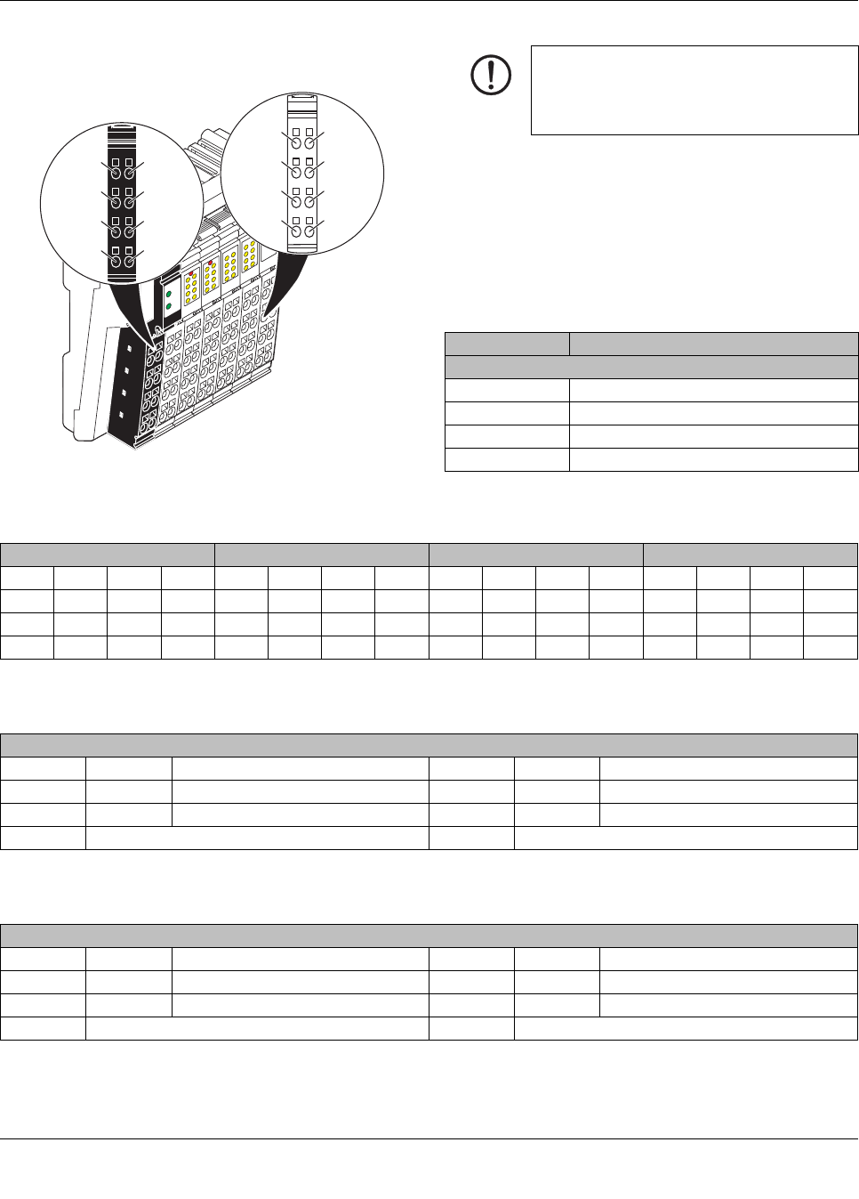
6 Local diagnostic and status
indicators
Figure 1 Diagnostic and status indicators
7 Connect supply, actuators, and
sensors
Figure 2 Connecting cables
•Strip 8 mm off the cables.
•Secure the cable by removing the screwdriver.
LED Color Meaning
PWR
UA Green 24 V actuator supply
UL Green 24 V communications power
OUT
E Red Short circuit/overload at one of the
outputs
1 ... 16 Yellow Status of the outputs
IN
1 ... 16 Yellow Status of the inputs
FS
FS Red Wireless connection interrupted,
analog and digital outputs set to 0
LINK QUALITY
LQ Green Link quality (bit error rate)
4 LEDs 0%...0,05%
3 LEDs 0,05%...1%
2 LEDs 0.1%...1.7%
1 LED >1.7%
OFF No connection established
If the error LED of a group of 16outputs lights
up (e.g.,connector 2 and 3), this indicates
that a short circuit or overload is present at
one or more of the outputs in this group.
DI16
16
DO AO2 AI2
QUALITY
LINK
UA
UL
PWR1
FS
BLUETOOTH
UA
UL
PWR1
12
5
DO
16
DO
16
6
910
13 14
E
E
4
12
3
11
8
16
7
15
12
5 6
910
13 14
412
311
816
715
D16ID16I
FS
AO2 AI2
LINK
QUALITY
LINK
QUALITY
CAUTION: Electric shock
The device is only intended for operation with
SELV according to IEC 60950/EN 60950/VDE
0805.
A
B
ILB BT ADIO MUX...
Preliminary Preliminary Preliminary Preliminary
7173_en_11 PHOENIX CONTACT 12 / 18
7.1 Terminal point assignment
Figure 3 Terminal point assignment
The feeding points have the same ground potential. All
ground supplies on a device are electrically connected with
one another.
The communications power is also electrically connected
via all contacts. In this way, it can supply all potentials with
just one feed-in, without the need for additional terminals.
Power plug
Digital output and input connectors
Analog output connector
Analog input connector
DI16
16
DO AO2 AI2
QUALITY
LINK
UA
UL
PWR1
FS
BLUETOOTH
1
1
2
2
1
1
2
2
3
3
4
4
1
1
2
2
3
3
4
4
1.1
1.1
2.1
2.1
1.2
1.2
2.2
2.2
1.3
1.3
2.3
2.3
1.4
1.4
2.4
2.4
1
2-7
NOTE: device damage
The terminal points for GND and UL can have
a total current of 8A per terminal point. Make
sure that this value is not exceeded.
Terminal point Assignment
Connector 1: PWR
1.1, 2.1 24 V actuator supply
1.2, 2.2 24 V communications power
1.3, 2.3 GND
1.4, 2.4 FE
Connector 2: OUT1 Connector 3: OUT2 Connector 4: IN1 Connector 5: IN2
1.1 O1 2.1 O2 1.1 O9 2.1 O10 1.1 I1 2.1 I2 1.1 I9 2.1 I10
1.2 O3 2.2 O4 1.2 O11 2.2 O12 1.2 I3 2.2 I4 1.2 I11 2.2 I12
1.3 O5 2.3 O6 1.3 O13 2.3 O14 1.3 I5 2.3 I6 1.3 I13 2.3 I14
1.4 O7 2.4 O8 1.4 O15 2.4 O16 1.4 I7 2.4 I8 1.4 I15 2.4 I16
Connector 6: Analog OUT
1.1 +U1 Channel 1 voltage output 2.1 +U2 Channel 2 voltage output
1.2 +I1 Current output channel 1 2.2 +I2 Current output channel 2
1.3 AGND Analog ground 2.3 AGND Analog ground
1.4 Shield connection 2.4 Shield connection
Connector 7: Analog IN
1.1 +U1 Voltage input, channel 1 2.1 +U2 Voltage input, channel 2
1.2 +I1 Current input, channel 1 2.2 +I2 Current input, channel 2
1.3 AGND Analog ground 2.3 AGND Analog ground
1.4 Shield connection 2.4 Shield connection
ILB BT ADIO MUX...
Preliminary Preliminary Preliminary Preliminary
7173_en_11 PHOENIX CONTACT 13 / 18
8 Basic circuit diagram
Figure 4 Basic circuit diagram
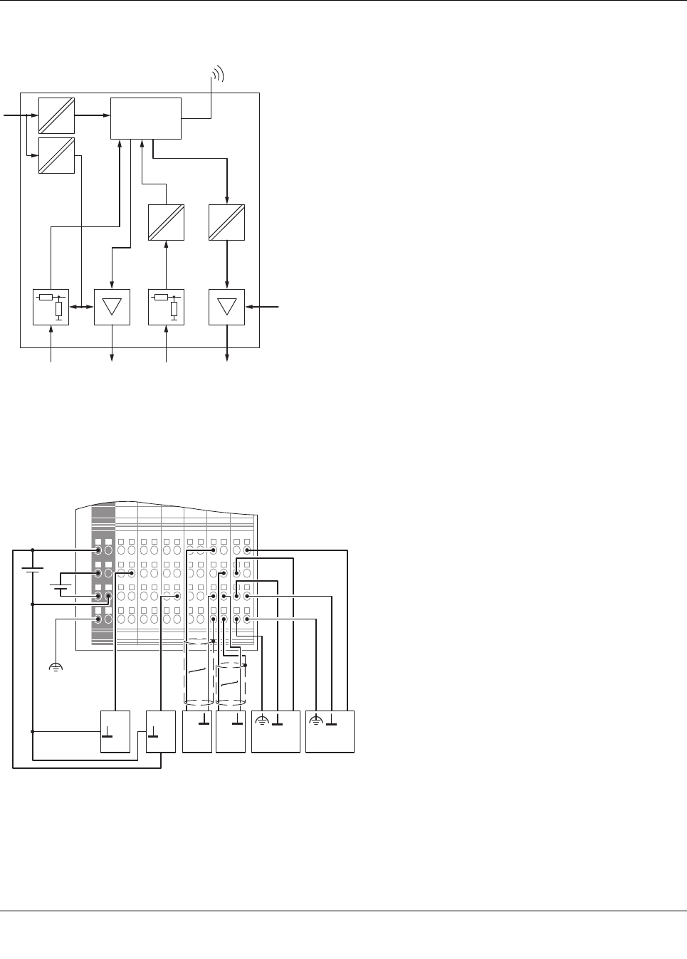
9 Connection example
The numbers above the device identify the connector slots.
Figure 5 Connection example
IN OUT OUT
Analog Digital
24 V DC
3,3 V DC
24 V DC
15 V DC
μC
IN
U
L
U
A
1234567
OUT 4 IN 6
24V
OUT
A
OUT
B
IN
C
IN
D
-
UA
+
-
UL
+
AActuator at the voltage output (channel1)
BActuator at the current output (channel2)
CActive sensor with current output (channel1)
DActive sensor with voltage output (channel2)
ILB BT ADIO MUX...
Preliminary Preliminary Preliminary Preliminary
7173_en_11 PHOENIX CONTACT 14 / 18
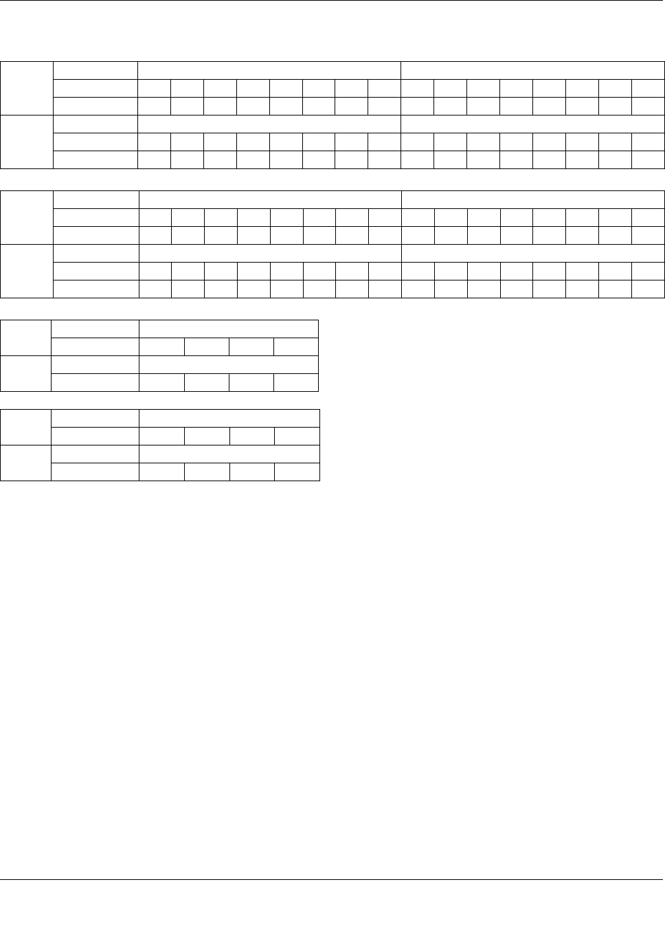
10 Assignment of terminal points to the remote station
Master Slot 4 (IN) 5 (IN)
Terminal point1.12.11.22.21.32.31.42.41.12.11.22.21.32.31.42.4
LED 1234567812345678
Slave Slot 2 (OUT) 3 (OUT)
Terminal point1.12.11.22.21.32.31.42.41.12.11.22.21.32.31.42.4
LED 1234567812345678
Slave Slot 4 (IN) 5 (IN)
Terminal point 1.1 2.1 1.2 2.2 1.3 2.3 1.4 2.4 1.1 2.1 1.2 2.2 1.3 2.3 1.4 2.4
LED 1234567812345678
Master Slot 2 (OUT) 3 (OUT)
Terminal point 1.1 2.1 1.2 2.2 1.3 2.3 1.4 2.4 1.1 2.1 1.2 2.2 1.3 2.3 1.4 2.4
LED 1234567812345678
Master Slot Connector 7: Analog IN
Terminal point 1.1 2.1 1.2 2.2
Slave Slot Connector 6: Analog OUT
Terminal point 1.1 2.1 1.2 2.2
Slave Slot Connector 7: Analog IN
Terminal point 1.1 2.1 1.2 2.2
Master Slot Connector 6: Analog OUT
Terminal point 1.1 2.1 1.2 2.2

ILB BT ADIO MUX...
Preliminary Preliminary Preliminary Preliminary
7173_en_11 PHOENIX CONTACT 15 / 18
11 Antennas
When installing two antennas, it is desirable to have a line of
sight between them wherever possible, as any obstacles
between the antennas will impair the connection.
The Fresnel zone, which extends around the direct
connecting line between transmitting and receiving
antennas, should also be taken into account. For an
optimum wireless connection, this zone must be free of
obstacles.
Figure 6 Fresnel zone
The radius of the Fresnel zone depends on the transmission
frequency and the distance between the transmitting and
receiving antennas. The radius corresponds to the minimum
height of the antenna mast if the terrain is flat.
Figure 7 Radius depending on the distance
Example: for a distance of 100meters, you must install the
antenna at a minimum height of 1.8meters. The Fresnel
zone can then be formed.
11.1 Omnidirectional antennas
Areas of application for omnidirectional antennas:
– Where the position of the transmitter and receiver may
change, e.g.,in moving applications
– In applications with no line of sight, because the signal
then travels from the transmitter to the receiver via
reflections
Assembly
Choose a location that provides a clear signal path in the
direction of the partner antenna. The ideal installation
location is the top of a mast or on a control cabinet. This
ensures that the antenna has the largest possible amount of
free space around it.
In this case, an omnidirectional antenna has almost uniform
directional characteristics over 360° on the horizontal plane.
Unfortunately, optimum installation of the antenna is not
always possible. If an omnidirectional antenna is mounted
on the side of a mast or control cabinet, specific distances
must be observed.
Figure 8 Antenna with preferred direction (1) and
antenna with substantially reduced range (2)
•In order to achieve a high transmission speed, observe
the Link Quality display during startup.
•Install the antennas in such a way that at least three
LEDs light up.
Depending on the system, occasional fluctuations in the
display may occur during operation.
r
d
1 2
AAntenna Antenna
BMast or surface (diameter or width)
CAntenna distance = 3cm Antenna distance = 6cm
ILB BT ADIO MUX...
Preliminary Preliminary Preliminary Preliminary
7173_en_11 PHOENIX CONTACT 16 / 18
Figure 9 Horizontal
Figure 10 Vertical
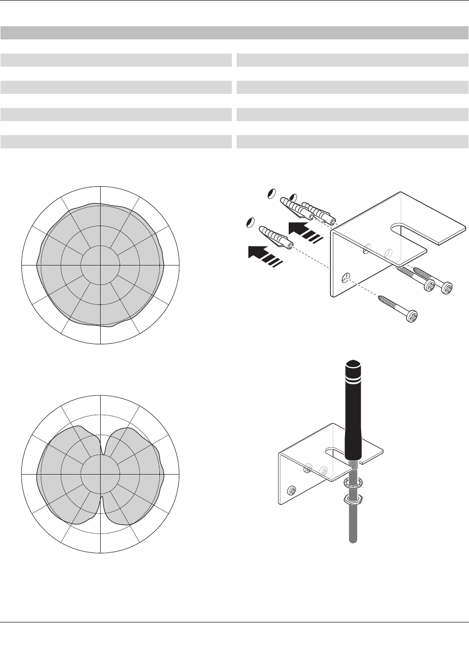
Wall mounting
Figure 11 Mounting brackets
Figure 12 Wall mounting
RAD-ISM-2400-ANT-OMNI-2-1-RSMA omnidirectional antenna (supplied as standard)
Order No. 2701362
Temperature range -20°C ... +65°C
Degree of protection IP65
Impedance 50Ω
Gain 2dBi
Cable length 1.5m
Connection RSMA (male)
Horizontal / vertical apex angle 360°/75°
VSWR ≤2
90
60
30
0
120
150
180
-150
-120
-90
-60
-30
0-30
90
60
30
0
120
150
180
-150
-120
-90
-60
-30
0-30
ILB BT ADIO MUX...
Preliminary Preliminary Preliminary Preliminary
7173_en_11 PHOENIX CONTACT 17 / 18
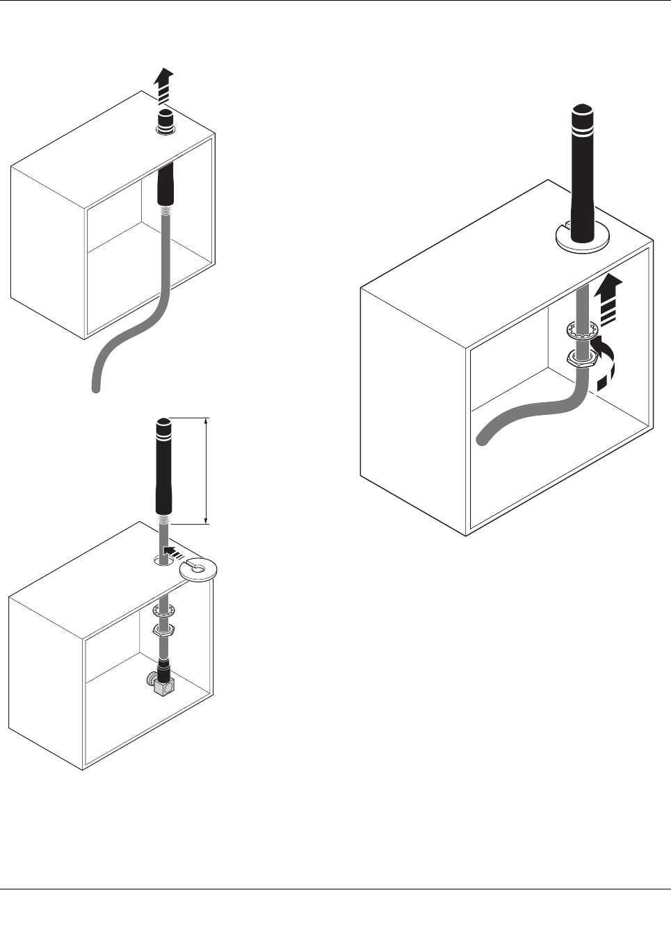
Mounting on the control cabinet
Figure 13 Control cabinet feed-through
Figure 14 Mounting on the control cabinet
Ø10
82,5
ILB BT ADIO MUX...
Preliminary Preliminary Preliminary Preliminary
7173_en_11 18 / 18
PHOENIX CONTACT GmbH & Co. KG • 32823 Blomberg • Germany
phoenixcontact.com
11.2 Range
Specifying ranges is very difficult due to the influence of
various factors. Based on practical tests, it is possible to
provide the following guide values. They may be
significantly higher or lower depending on the actual
application.
The range depends on the following:
– Length of the antenna cable (the shorter the cable, the
lower the attenuation)
– Antenna used
– Mounting location
– Line of sight
– Adherence to the Fresnel zone
In order to minimize signal losses, keep the antenna cable
as short as possible.
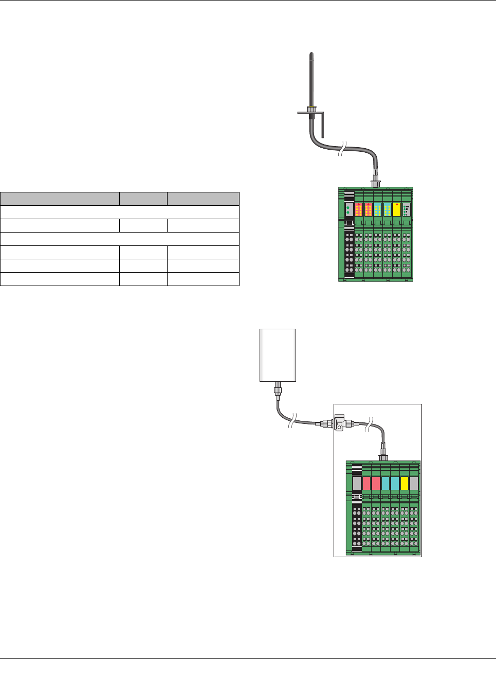
11.3 Typical combinations of antennas and adapter
cables
Figure 15 Omnidirectional antenna, 2dBi, supplied as
standard
Figure 16 Directional antenna, 9dBi, with surge
protection
Antenna Gain Range [m]
Indoors, free line of sight
Omnidirectional antenna 2dBi 50 ... 100
Outdoors, free line of sight
Omnidirectional antenna 2dBi < 200
Omnidirectional antenna 6dBi < 300
Panel directional antenna 9dBi < 400
UA
UL
PWR1 DO
16
DI 16
FS
AO2 LINK
QUALITY
AI2