Phottix JUNOTTL Phottix Juno TTL Transceiver Flash User Manual
Phottix (HK) Ltd. Phottix Juno TTL Transceiver Flash
Phottix >
User manual
En INSTRUCTION MANUAL
1
INSTRUCTION MANUAL
說明書
En
Cn Trad
Phottix Juno TTL
Transceiver Flash

2

En INSTRUCTION MANUAL
3
Note: To start immediately using this ash please refer to the Quick-Start guide.
For advanced features please read this manual and be familiar with your camera
manual and operations.
The Phottix Juno TTL Transceiver Flash for Canon is designed to work with
Canon DSLR cameras and features ETTL I/II, Manual, Multi Modes as well as
Wireless (Radio and Optical) triggering.
Warnings
1. Use your ash safely. Do not re the ash into the eyes of people or animals at
short distances – damage and/or blindness can occur.
2. Be careful using the flash in or around cars, buses, motorcycles or other
moving vehicles as accidents can result.
3. Never use the ash near combustible gases (gasoline, solvents, etc.).
4. Do not expose the flash or batteries to dripping/splashing water, or high
humidity.
5. Do not leave the ash or batteries in a hot location (direct sunlight, in a closed
car, etc.).
6. Remove batteries from the ash when not being used for an extended period
of time.
7. Change the batteries when required. Use undamaged batteries in good
condition. Do not mix battery types or new and used batteries.
8. Do not put opaque objects in front of the ash lens when ring the ash. The
energy emitted by the ash may cause objects to burn, or cause damage to the
ash tube or fresnel lens.
9. Use caution in touching the ash head after use. It may be hot and can cause
burns.
10. The flash contains high voltage electronic parts. Do not disassemble or
attempt to repair the ash. Never touch the ash’s internal components.
11. Do not touch the External Power Port contacts with any metal objects – this
can cause electric shock and serious injury.
Table of contents
1. Parts and Function .......................................................................................... 4
2. Flash Set-up ....................................................................................................... 5
3. LCD display ........................................................................................................ 9
4. Functions and Operations ............................................................................14
5. Wireless triggering ..........................................................................................19
6. Other Functions .............................................................................................. 29
7. Custom Function ............................................................................................ 29
8. Technical Specications ............................................................................... 31
9. Appendix ........................................................................................................... 32
4
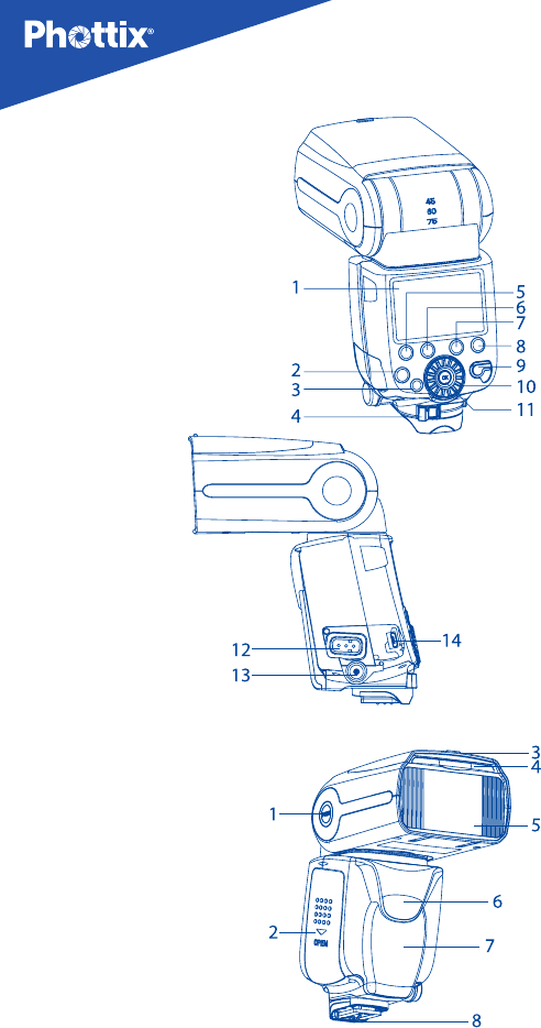
1. Parts
Back/Left side
1. LCD Display
2. Mode Button
3. Test Button/ Ready Light
4. Locking Lever
5. Function Button 1
6. Function Button 2
7. Function Button 3
8. Function Button 4
9. Power Switch
10. Selection Dial
11. OK Button
12. External Power Port
13. PC Sync Port
14. Micro USB Port
Front/Right side
1. Flash Head Locking Button
2. Battery Compartment
3. Bounce Card
4. Wide Angle Diuser
5. Flash Head
6. Optical Signal Receiver
7. AF Assist Light
8. Hot Shoe

En INSTRUCTION MANUAL
5
2. Flash Set-up
This manual assumes:
1. Both the ash and camera are switched on.
2. The ash and camera are set to the same settings as this manual.
3. Camera menu and ash custom Functions menu are set to default values.
4. The ash is being used with a compatible camera.
Installing Batteries
1. Press the battery cover in while pushing it towards the bottom of the ash.
The battery cover will open and raise.
2. Insert AA batteries as shown by the diagram inside the battery compartment
3. Lower the battery cover and push back towards the top of the ash, locking it
in place.
Please note:
- Please use four standard high-quality batteries of the same brand. Make sure
all batteries are at similar power levels.
- Batteries can get hot when the flash is being used. Use caution when
changing batteries.
- If you do not use the flash for an extended period of time, store with
batteries removed.
- The Juno TTL Flash circuitry is designed to be used with either Alkaline, Ni-
CD or NiMH rechargeable batteries. Do not use Lithium AA batteries.
Battery Level Indicator
The Battery Level Indicator on the LCD (see below) will display an approximate
indication of how much power remains in the batteries in the ash. Use this as
a rough guide as to when a battery change is needed. If ash recycling time has
become very long (30 seconds) change the batteries.
Status LED
Flash-ready indicator. In Quick Flash Mode, the LED will turn green when the
ash has the minimum recycle charge. It will turn red when fully charged.
External Battery Port
The External Battery Port is compatible with the Canon CP-E4 compact battery
packs, or compatible equivalents.

6
Please note:
- Batteries must be used in the ash even when an external battery pack is
used.
- Do not use non Canon-compatible battery packs.
Overheating Protection
The Phottix Juno TTL contains an overheating protection circuit that will slow
ash recycle time to avoid overheating-related damage. Approximately 30 full-
power ashes in a short amount of time will trigger this protection. Stop using
the ash and wait 10 minutes for it to cool down.
Sync and USB Ports
1. The PC Sync Port can be used with a PC Sync Cable to trigger the ash – from
a ash trigger or camera. This port is input only – ash signals are not output
from this port.
2. The Micro USB port is used for rmware upgrades. Firmware announcements
and instructions will be made available on Phottix websites.
Attaching the Flash to the camera
1. Turn o both the camera and ash
2. Align the ash hot shoe with the camera hot shoe.
3. Slide the ash into the camera hot shoe until fully inserted.
4. Lock the ash in position by pushing the locking lever to the right until the lock
engages with a click.
5. To Unlock, press the locking release Button on the locking lever and slide to
the left.
Turning the Flash On/ O
1. To power on the ash move the power switch to the on position.
2. To power o the ash move the power switch to the o position.
3. To Lock the ash:Move the power switch to the“LOCK”positios. This “locks”
the Buttons and Dial of the ash, so setting cannot be accidentally changed.
Raising and Rotating the Flash Head
1. The ash head will elevate from -7 to 90 degrees with stops at -7, 0, 45, 60, 75
and 90 degrees.
2. To Adjust: Press the Flash Head Locking Button and gently raise or lower the
ash head into the desired position.

En INSTRUCTION MANUAL
7
3. The ash head will rotate 180 degrees in either direction with stops at 30, 60,
90, 120, 150 and 180 degrees.
4. To Adjust: Press the Flash Head Locking Button and gently rotate the flash
head into the desired position.
5. When the ash head is raised or rotated from the 0 degree standard forward
position the ash zoom will set itself to 50mm. “- -” will be displayed on the LCD.
Flash zoom when the head is raised or rotated can be changed in MZoom Mode
(see below).
6. At -7 degrees the ash zoom will act the same as 0 degree – it will not change
any settings.
Using the Bounce Card or Wide Angle Diuser
The Phottix Juno TTL Flash comes equipped with a White Bounce Card and Wide
Angle Diuser Panel in the ash head.
1. The Wide Angle Diuser Panel will cause the ash to spread light to a 14mm
equivalent.
2. The White Bounce Card can be used when the ash head is in a raised position
to bounce light forward to assist with catch lights in a subject’s eyes.
To use:
1. Gently pull the Diuser Panel and Bounce Card from the Flash Head using
the ridge on the bottom of the Diuser Panel.
2. If using the Diffuser Panel it will drop into position over the Flash Head.
Gently push the Bounce Card back into the Flash Head if not needed.
3. If using the Bounce Card only gently push the Diuser Panel back into the
Flash Head.
Using the Flash Head Diuser
The Phottix Juno TTL Flash comes with an attachable diffuser that can be
added to the front of the ash head when needed. It is good for softening light,
reducing hot spots and shadows and better coverage for macro photography.
Setting ash zoom
There are two ways to control the zoom of the flash while it is on camera:
automatic (Azoom) and manual (Mzoom)。 While in automatic zoom, the zoom
on the ash will follow the zoom of the lens to provide the best coverage. When
in manual zoom, the zoom setting on the ash is set by the user.
Setting the ash zoom
1. Press the Function Button underneath or (depending on
the ash Mode)to enter the ash zoom adjustment Mode.

8
2. Use the Selection Dial to set Automatic Zoom Mode (Azoom) or set the
manual zoom value (Mzoom).
3. When nished, press the OK Button to exit.
Please note:
1. When in Azoom and the ash head is raised or rotated from the 0 degree
standard forward position - the ash zoom will set itself to 50mm. “- -” will be
displayed on the LCD. The ash zoom will not change if the head is lowered to
-7 degrees.
2. Azoom will work ONLY when the ash head is set to either 0 or -7 degrees.
3. When using Mzoom and the flash head is raised or rotated from the 0
degree standard forward position - the ash zoom will not be changed from
the previous setting.
4. Flash Zoom can be adjusted when the head is raised or rotated by switching
to Mzoom Mode and making desired adjustments.
Test Button
Pressing the test Button will trigger the ash. This can be used for metering (in
manual Mode only). In Wireless Master Mode pressing the test Button will re
slave ashes on the same channel, group and matching ID being controlled by
the Master ash.
Modeling Flash
1. Pressing the camera depth-of-eld preview Button (if available) will re the
ash continuously for 1 second. This Modeling Flash is useful in seeing lighting
eects and balance on the subject. (Please see your camera manual for more
information on the DOF Button and Button assignment.)
2. Modeling Flash is available in all Modes, TTL, Multi and Manual.
Please note:
1. Overheating and damage can result from excessive use of the Modeling
Flash. Do not use more than 20 times in succession.
2. When overheating the ash will automatically increase charging time until
the ash temperature has decreased.
Autofocus (AF) Assist Light
1. In low light/contrast situations the Phottix Juno TTL built-in Auto Focus Assist
Light will illuminate to assist with AF. The AF Assist Light on the front of the ash
will project a focusing target on the subject.
2. AF Assist Light Functions can be set to on or o (see C.Fn-03 below).
Note:
AF assist light will not work when ash is in Receiver or Slave Mode.
En INSTRUCTION MANUAL
9
3. The LCD Display
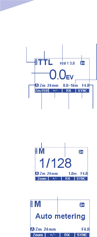
TTL Auto Flash Mode:
TTL:TTL Auto
Flash Mode
Flash Exposure
Bracketing
Battery Level
Indicator
Aperture Value
Distance
Indicator display
First Curtain Sync Mode
High Speed Sync Mode
Second Curtain Sync Mode
Flash Exposure
Compensation
(FEC)
Zoom/ Flash
Exposure Bracketing
Selection Button
Wireless Receiving
Mode Selection Button
Flash Exposure
Compensation
Selection Button
Sync Mode
Selection Button
Azoom:Auto Zoom
Mzoom:Manual Zoom
Manual Flash Mode
Power LevelM:Manual Flash
Auto Metering Mode
10
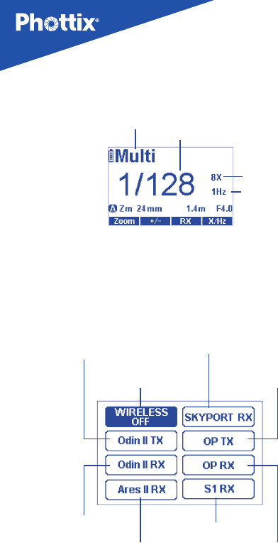
Stroboscopic Flash Mode
Frequency
Flash Count
Power Level
Multi:Stroboscopic Flash
Wireless Flash Selection Menu
Wireless Function off
Optical Mode:
Infrared Transmitter
(Master) Mode
Optical Mode:
Infrared Receiver
Slave Mode
Optical Mode:
Optical Slave
Radio:
Ares II Receiver
Radio: Odin II
Receiver Mode
Radio: Odin II
Transmitter Mode
Radio: SKYPORT
Receiving Mode
En INSTRUCTION MANUAL
11
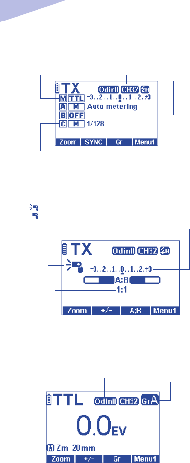
Wireless Mode:Odin II Transmitter Mixed TTL/M Mode
Master Flash Group Channels
Odin II Transmitter Flash Group
Flash Mode:
Selectable between
TTL/M/OFF
Wireless Radio Mode:Odin II Transmitter Ratio Mode
Flash Ratio
Flash Exposure
Compensation of the Ratio
:Master Flash On
:Master Flash Off
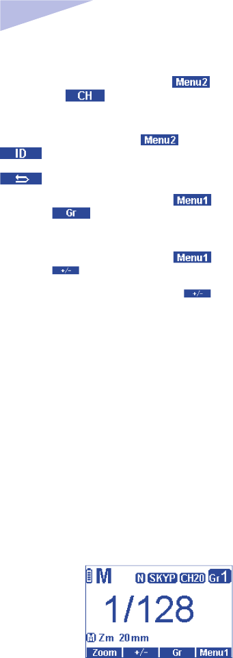
Wireless radio Mode:Odin II Receiver Mode
Wireless Radio Mode:
Odin II Receiver Mode Receiver Group
12
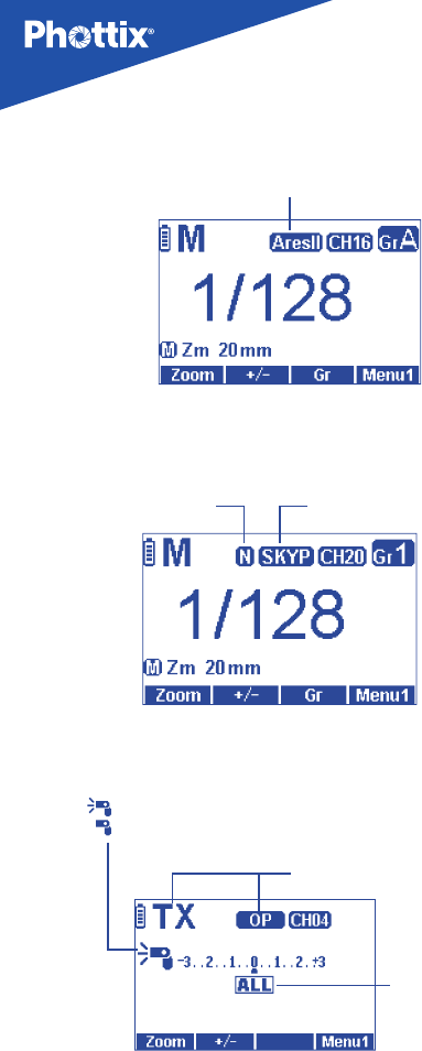
Wireless Radio Mode:Ares II Receiver Mode
Wireless Radio Mode:
Ares II Receiver Mode
Wireless radio Mode:Skyport RX Receiver Mode
Signal Transmit Rate:
Normal/Speed Wireless Radio Mode:
Skyport Receiver Mode
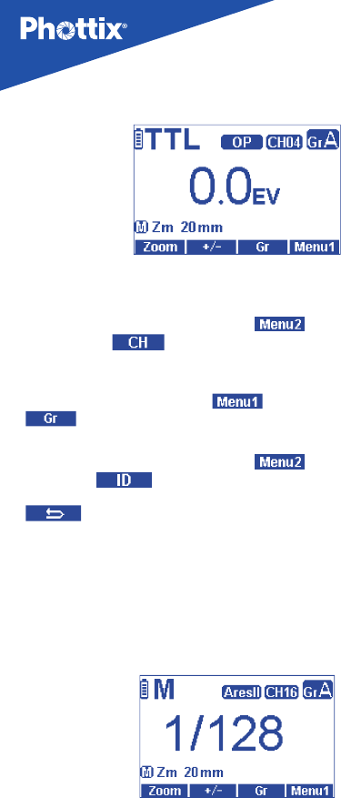
Optical Mode: Infrared Transmitter (Master) Mode
Optical Mode:
Infrared (Master) Mode
TTL Flash Group
: Master Flash On
: Master Flash Off
En INSTRUCTION MANUAL
13
Flash Ratio
Master Flash
Infrared Transmitter Group Flash Power
Optical Mode:Infrared Receiver (Slave) Mode
Optical Mode:
Infrared Receiver
(Slave) Mode Optical Slave Group
14
Optical Mode:Optical Slave Mode
Optical Mode:Optical Slave Mode
4. Functions and Operations
Standard Flash Mode (Wireless OFF)
There are 3 flash Mode available:Auto(TTL)、Manual(M)and
Stroboscopic(Multi).
Changing Flash Mode:
Pressing the“MODE”Button will cycle between Auto(TTL)、Manual(M)
and Stroboscopic(Multi)。The selected Flash Mode will display on the upper
left corner of the LCD.
TTL: Auto Flash
In TTL Mode the ash and camera will work together to calculate the correct
exposure. When the Shutter Button is fully pressed the flash will fire a pre-
ash that the camera will use to calculate exposure and ash power the instant
before the photo is taken.
Flash Exposure Compensation (FEC)
The Juno TTL Flash allows Flash Exposure Compensation (FEC) adjustment from
-3 to +3 in 1/3rd stops. This is useful in situations where ne-tuning of the TTL
system is needed based on the environment.

En INSTRUCTION MANUAL
15
To set FEC:
1. Press “MODE” Button until the ash display TTL on the top left corner of the
LCD.
2. Press Button to enter FEC Adjustment Mode
3. Use the“Selection Dial”to adjust the FEC
4. Press to exit.
Flash Exposure Bracketing – FEB
Flash Exposure Bracketing (FEB) can be used to automatically change flash
power over a series of photos. The camera will record three images with dierent
exposures – one exposed as per camera calculations, one over-exposed and
another under-exposed. Over and under exposure levels can be set by the user.
FEB is useful in run-and-gun situations as well as when shooting scenes with
different lighting conditions to help ensure a properly exposed photo. It can
also be used for HDR photography. Some cameras have ash exposure storage
Function, see your camera user manual for more details.
1. Hold down the Button for 2 seconds. The FEC icon will displayed
in the top right hand corner of the LCD .
2. Use the“Selection Dial”to adjust the exposure bracket amount, once
selected, ash will re in sequence of the selected FEC.
Cancel FEB :
1. Hold Button for 2s, use the“Selection Dial”to set FEB to ±0 .
Please note:
- FEB can be used in conjunction with FEC and Flash Exposure Lock (FEL)
- For best result, set the camera drive Mode to single frame, and before the
second and third picture is taken, make sure the ash is fully recycled.
Flash Exposure Lock–FEL
The Juno TTL is compatible with Flash Exposure Lock (FEL) Functionality. FEL can
be used to lock the ash exposure before a photo is taken. See your camera user
manual for further details on using FEL.
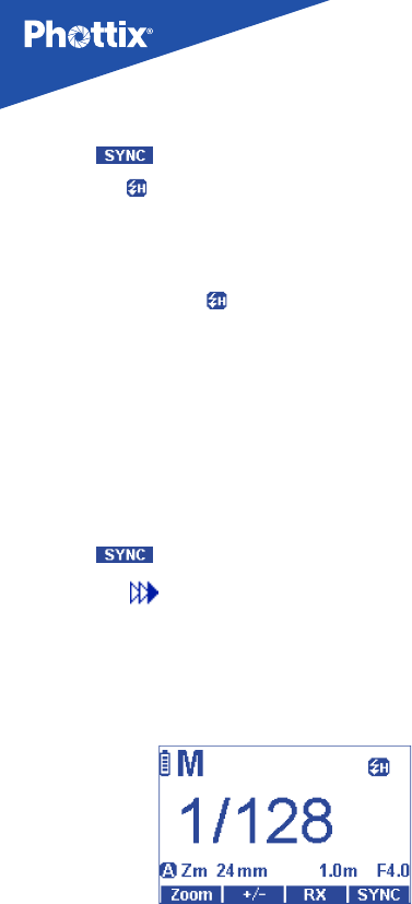
High Speed Sync – HSS
In HSS Mode, the camera/flash maximum sync speed can reach the camera’s
maximum shutter speed. This is useful when using Aperture Priority Mode or
to limit ambient light. HSS may vary with dierent camera models - see your
camera user manual for details.
16
To use HSS Mode:
1. Press Button to cycle through the Sync Mode of the ash.
2. When the icon is displayed, the ash is set at HSS Mode
3. You can now set the camera to use a shutter speed faster than the sync
speed for the camera
Please note:
Check that the HSS icon( ) is displayed in the viewnder
- HSS drastically reduces ash power, battery power and range.
- HSS is not available in Stroboscopic Mode
Second Curtain Sync – SCS
The Phottix Juno TTL Second Curtain Sync Function makes the ash re at the
end of an exposure, not the beginning. This can be useful with slow shutter
speeds for capturing special eect.
To use:
1. Press Button to cycle through the Sync Mode of the ash.
2. When the icon is displayed, the ash is set at SCS Mode
Note:
SCS Function is not available in Stroboscopic Mode
M: Manual Mode
In Manual Mode the ash will re at the power level set on the ash. The Phottix
Juno TTL Flash can be adjusted from 1/1 (full power) to 1/128 – 8 stops of
adjustments in 1/3rd stop increments. Aperture, shutter speed and ISO on the
camera need to be manual adjusted. For best results use camera M-Manual
Mode.
To use:
1. Press “MODE” Button until the ash displays M on the top left corner of the
LCD.
En INSTRUCTION MANUAL
17
2. Press Button to enter Manual Power Adjustment Mode.
3. Use the “Selection Dial” to adjust the Power Level.
4. Press to exit.
Note: Half press the camera Shutter Button will display t he eective manual
ash power range on the Flash LCD.
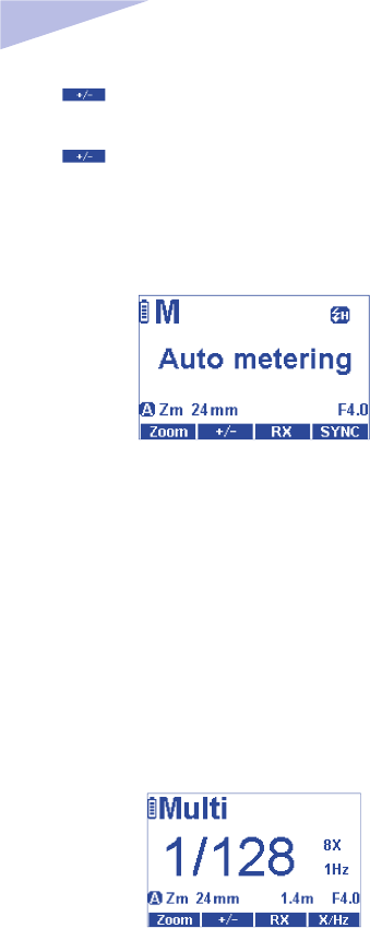
Auto-Metering Mode
Auto Metering Mode can be used similarly to a light Meter to measure and set
the ash power needed for proper exposure.
To use:
1. While in Manual (M) Mode – press and hold the OK Button for 2 seconds.
2. Auto Metering will be display on the ash LCD
3. When a photo is taken the flash will automatically calculate the manual
power level and display it on the back of the ash.
4. Subsequent photos will be taken at this power level.
5. To re-meter press and hold the OK Button for 2 seconds to re-enter Auto
Metering Mode.
Multi: Stroboscopic Mode
With Multi Stroboscopic Mode a series of rapid ashes will be red. The ash
count, frequency and power of these ashes can be programmed on the Phottix
Juno TTL. Multi Mode is useful for capturing multiple images of a moving
subject in the same photo and other special eects. The frequency of the eect
(in Hz. - number of ashes per second), the total number of ashes and output
levels can be set.

18
To Use:
1. Press “MODE” Button until the ash displays Multi on the top left corner of
the LCD.
2. Press Button to enter Power Adjustment Mode, use the Selection
Dial to adjust the ash power
4. Press Button to cycle through Number of Flashes (X) and frequency
(Hz), and use the Selection Dial to adjust these settings.
Please note:
1. Overheating and damage can result from excessive use of the Multi
Stroboscopic Mode. Do not use more than 20 times in succession.
2. When overheated the ash will automatically increase recycling time until
the ash temperature has decreased.
Stroboscopic Mode and Shutter Speeds
To determine the proper camera shutter speed to be used with various
Stroboscopic Mode variables, use the following formula: Number of flashes /
Frequency = Shutter Speed
Example: 5x (number of ashes) / 10 Hz (Frequency) = .5 second shutter speed.
This is a rough guideline: You may need to increase or decrease the shutter
speed to get the desired result.
Multi Stroboscopic Mode Output Chart
1/4
1/8
1/16
1/32
1/64
1/128
7
14
30
60
90
100
6
14
30
60
90
100
5
12
30
60
90
100
4
10
20
50
80
100
4
8
20
50
80
100
3
6
20
40
70
90
3
5
10
30
60
80
2
4
8
20
50
70
2
4
8
20
40
70
2
4
8
20
40
60
2
4
8
18
35
50
2
4
8
16
30
40
2
4
8
12
20
40
1 2 3 4 5 6-7 8-9 10 11 12-
14
15-
19
20-
50
60-
199
HZ
Flash
Output
If the number of ashes is displayed as “N---”, the maximum number of ashes
will be as shown by the table below regardless of the ring frequency.
Flash output 1/4 1/8 1/16 1/32 1/64 1/128
Flash count 2 4 8 12 20 40
En INSTRUCTION MANUAL
19
5. Wireless Triggering Modes
The Phottix Juno TTL Flash is equipped with several wireless transmitter and
receiver Modes. It oers built-in compatibility with the Phottix Odin II TTL Trigger
system, Phottix Odin Lite, Phottix Ares II and Elinchrom Skyport. Compatibility
for Canon’s native optical master/slave triggering system is also included. For
information on these systems please consult the respective product manuals.
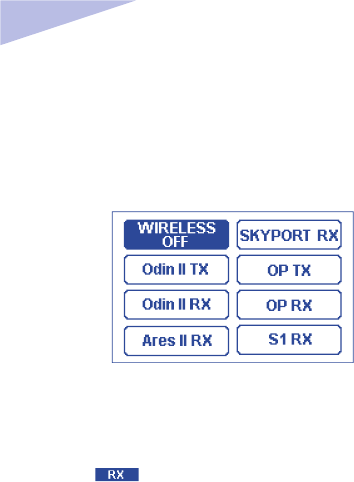
Selecting Wireless Triggering Mode
To set the wireless triggering Modes on the Juno TTL
1. Press the Function Button to enter the Wireless Triggering Mode
Selection screen
2. Use the Selection Dial to select the desired Wireless Triggering Mode and
press the OK Button to select.
3. Set the parameters for the selected Wireless Triggering Mode (e,g: Channels
and groups).
Wireless Triggering Mode available on Juno TTL:
Odin II Tx(Transmitter)
Allows full adjustments to local and remote TTL and Manual ash power and
zoom on other Juno TTL flashes (in Odin II Rx Mode) or compatible flashes
equipped with Phottix Odin II receivers. Flashes or studio lights with Strato II or
Ares II receivers can be triggered in manual Mode by the Juno TTL ash in Odin
II Tx Mode.
Note: Odin Z OS require on Odin II receiver
Odin II Rx(Receiver)
The Juno TTL flash in Odin II Rx Wireless Mode can be triggered by another
Juno TTL ash in Odin II Tx Mode or by a Phottix Odin II Transmitter. If using an
Odin II Tranmitter (for any brand) the Juno TTL in Odin II Rx Wireless Mode will
automatically switch to Canon, Nikon, Sony and Pentax compatibility.
Note: Odin II Canon, Nikon and Sony requires Odin Z OS

20
Ares II Rx(Receiver)
The Juno TTL in Ares II Rx Wireless Mode can be triggered by Phottix Ares II
Transmitters, Phottix Odin II Transmitters and Phottix Juno TTL ash in Odin II Tx
Mode.
Skyport RX(Receiver)
In Skyport Rx Mode, the Juno TTL flash can be triggered by Elinchrom EL
Skyport Transmitter Plus, Elinchrom EL Skyport Transmitter Plus HS, Elinchrom
EL Skyport transmitter Pro.
OP Tx(Master)— Using Canon Infrared triggering system
Using pulses of light, the Juno TTL ash on camera can adjust and re remote
ashes in OP Rx Mode .
OP Rx (Slave)—Using Canon Infrared triggering system
Remote Juno TTL (Canon) in OP Rx Mode are controlled and red by on-camera
ashes in OP Tx Master Mode.
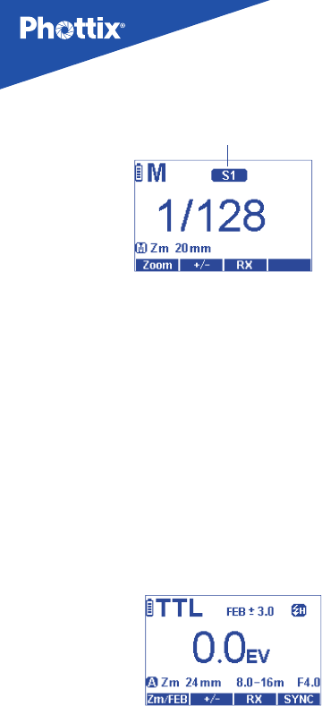
Note: Both OP Tx and OP Rx ash needs to be Juno TTL for Canon.
S1 Rx (Slave)— Optical Slave
In S1 Rx Mode other nearby ashes will trigger the Juno TTL in manual Mode
only when they are red.
Please note: The Juno TTL cannot be triggered by Phottix Strato, Odin I TCU or
Ares .
In the wireless triggering Mode Selection screen, if the OK Button is not pressed,
after 12 seconds the ash will enter the current selected Wireless Mode.
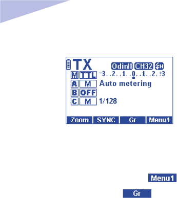
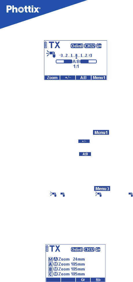
OdinII Tx (Transmitter Mode)
Using the Juno TTL Flash in Odin II Tx Mode allows for a ash to be used on-
camera in TTL or Manual Mode as well as control three groups (A, B, C) –
adjusting TTL and manual power levels as well as ash head zoom on Juno TTL
ashes set in Odin II Rx Mode or other compatible ashes mounted on Phottix
Odin II receivers. In ash groups under manual Mode can also set ‘auto metering’
feature to assist it setting the desired power.
En INSTRUCTION MANUAL
21
OdinII Tx Mode interface
Using OdinII Tx Mode
After selecting OdinII Tx Mode (above)
1. Press Function Button 4 until the LCD displays .
2. press Function Button 3 (underneath ) to cycle through M (Master
ash), A,B,C.
3. Pressing the Mode Button while a Group is selected will change the Mode
from TTL, M (Manual) and O.
4. Use the Selection Dial when a group is selected to adjust the EV Level ±3EV
in 1/3 stop in TTL Mode, or the power level (1/128 to 1/1 in 1/3 stops) in Manual
Mode.
4. Press the OK Button to conrm and exit the Odin II Tx Mode editing menu.
Setting in Odin TX wireless mode
The Auto Metering Mode can be used similarly to a light meter to measure and
set the ash power needed for proper exposure
To use auto metering:
1. Set the respective groups to Manual Mode (M), the groups can be set to
any power level
2. Press and hold the option/confirm button until the LCD displays Auto
Metering.
3. Take a test shot
4. The suggested power level will be displayed on the Odin II in the respective
groups.
Please Note:
· To Cancel Auto Metering: press the flash group button and the option/
conrm button to exit auto metering mode for that group.
· Press the test button to exit auto metering mode for all groups.
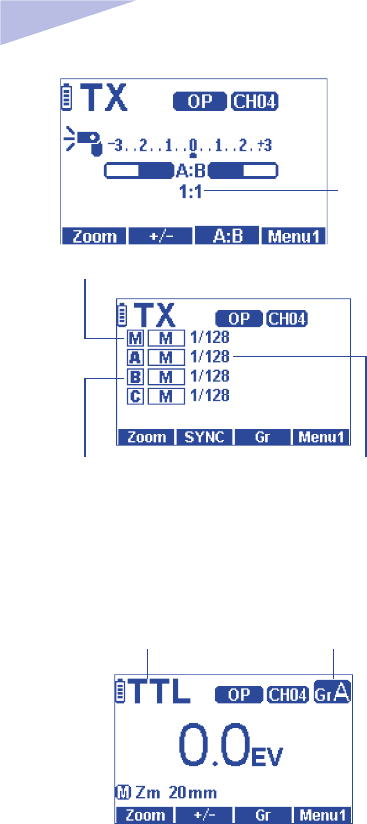
22
Odin II Tx Ratio Mode
Ratio Mode
Ratio is similar to Canon’s native TTL system. The ratio of Groups A and B can be
set from 8:1 to 1:8. EV levels can also be adjusted. Adjustments to the local ash
(M) Mode and power can be made.
To Use Ratio Mode:
1. In Odin II Tx Mode, press the “MODE” Button to access the Ratio Mode.
2. Press Function Button 4 until the LCD displays .
3. Press Function Button 2 (underneath ) to select local EV settings and
use the Selection Dial to adjust the EV. Press OK to conrm and exit.
4. Press Selection Button 3 (underneath ) and use the Selection Dial to
adjust the ratio between 8:1 to 1:8. Press OK to conrm the setting.
5. Pressing the“MODE”Button in Ratio Mode will exit Ratio Mode and return to
Standard Mode.
Setting the master ash:
1. Press Function Button 4 until the LCD displays . Pressing Function
Button 1 (underneath / ) can switch on ( ) or switch o ( ) the
master ash.
Please note
The ash on camera (M) is not part of the ratio calculation. Power for the local
ash is controlled independently.
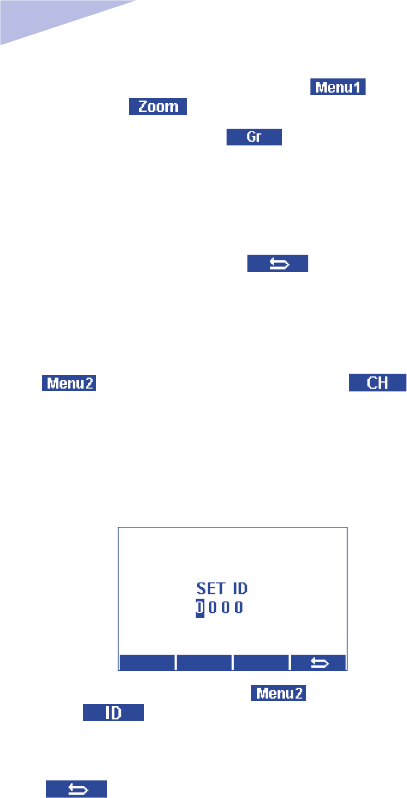
Flash Zoom adjustment in Odin II TX Mode
En INSTRUCTION MANUAL
23
1. Press Function Button 4 until the LCD displays . Press Function
Button 1 (underneath ) to access the zoom adjustment screen.
2. Press Function Button 3 (underneath ) to cycle through M(Master), A,
B, C groups
3. Use the Selection Dial to change the zoom of the selected group, the master
flash can be set to Azoom (automatic zoom that changes dynamically as a
zoom lens is changed) or Mzoom 20mm, 24 mm, 28 mm, 35 mm, 50 mm,7 0
mm, 80 mm, 105mm, 135mm and 200mm(Mzoom only in group A,B,C)
4. Press Selection Button 4(underneath ) to confirm and exit the
zoom adjustment screen.
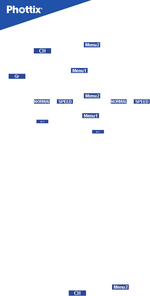
Setting channels
1. In Standard or Ratio Mode interface, press Function Button 4 to
access , and use Function Button 1 (underneath ) to enter
the Channels Selection area
2. Use the Selection Dial to cycle through CH 1-32 (Channels 1-32)
3. Press the OK Button to conrm and exit the channel Selection
Setting Digital ID
1. Press Function Button 4 to access , press Selection Button
2(underneath ) to enter the Digital ID Selection screen.
2. Press the OK Button to choose the digit in the ID, use the select Dial to change
the digit.
3. Press Button to conrm and exit the ID Selection screen.
Odin II Rx(receiver) Mode
When the Odin II Rx Wireless Mode is selected the Phottix Juno TTL Flash can
be controlled and triggered from another Juno TTL Flash in Odin Tx Mode or an
Odin II Transmitter.
24
Odin II Rx Mode screen
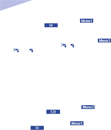
Changing channels, groups and ID
1. Press Function Button 4 to access , use Function Button 1
(underneath ) to enter the Channels adjustment area. Use the
Selection Dial to change the channels between CH1-CH32. Press the OK Button
to conrm and exit channel adjustment area.
2. Press Function Button 4 to access use Function Button 3 (underneath
) to enter groups adjustment area. Use the Selection Dial to change
the groups between A,B,C,D,E.
3. Press Function Button 4 to access , use Function Button 2
(underneath ) to enter ID adjustment screen. Press the ok Button to
choose the digit in the ID and use the Selection Dial to change the digit, press
Button to exit the ID interface
Please note:
In TTL Mode, the eect of EV adjustment is cumulative. If EV adjustment is set
on the Odin II Rx screen and on an Odin II Transmitter or Juno TTL in Odin II Tx
Mode, and/or in TTL Pref in the Custom Functions menu, all of these settings
will be used to calculate nal EV.
Ares II Rx(receiver) Mode screen
When the Ares II Rx Mode is selected, the Juno TTL will be triggered by Phottix
Ares II Transmitters, Phottix Odin II Transmitters or a Phottix Juno TTL Flash in
Odin II Tx Mode – when set to the same channel, group and Digital ID.
En INSTRUCTION MANUAL
25
Changing channels, groups, ID, power and ash Mode
1. Press Function Button 4 to access , use Function Button 1
(underneath ) to enter the Channels adjustment area. Use the
Selection Dial to change the channels between CH1-CH16. Press the OK Button
to conrm and exit channel adjustment area.
2. Press Function Button 4 to access use Function Button 2 (underneath
) to enter ID adjustment screen. Press the OK Button to choose
the digit in the ID and use the select Selection Dial to change the digit, press
Button to exit the Digital ID screen.
3. Press Function Button 4 to access use Function Button 3
(underneath ) to enter groups adjustment area. Use the Selection Dial
to change the Groups between A,B,C,D. pPress the OK Button to conrm and
exit group adjustment area.
4. Press Function Button 4 to access use Function Button 2
(underneath ) to enter power adjustment area. Use the Selection Dial to
change the power of the ash between 1/1 to 1/128 with 1/3 stops increments.
Press the Function Button correspond to to confirm and exit the
Selection screen
5. Use the Mode Button to change flash Mode between Manual (M) and
Stroboscopic (Multi.)
Please note:
- In Ares II Rx (Receiver) Mode there are no wireless TTL Functions such as HSS
or SCS, or wireless power/zoom control.
- Power and zoom levels must be set manually on the Juno TTL ash while in
Ares II Rx Mode.
- Digital ID is only available in CH5-16, CH1-4 cannot set.
ELINCHROM SKYPORT Rx(Receiver) Mode
When the Skyport Rx Mode is selected the Juno TTL Flash will be triggered by
Elinchrom EL Skyport Transmitter Plus, Elinchrom EL Skyport Transmitter speed,
Elinchrom EL Skyport Transmitter Pro, when set to the same channel, group and
Digital ID.
SKYPORT RX Mode screen
26
Changing channels, groups, sync Mode and power
1. Press Function Button 4 to access , use Function Button 1
(underneath ) to enter channels adjustment area. Use the Selection
Dial to change the channels between CH1-CH20. Press the OK Button to conrm
and exit channel adjustment status
2. Press Function Button 4 to access use Function Button 3 (underneath
) to enter groups adjustment area. Use the Selection Dial to change
the groups between 1,2,3,4. Press the OK Button to confirm and exit group
adjustment status
3. Press Function Button 4 to access , use Function Button 2
(underneath or )to cycle between or
Modes.
4. Press Function Button 4 to access use the Function Button 2
(underneath ) to enter power adjustment area. Use Selection Dial to
change the power of the ash between 1/1 to 1/128 with 1/3 stops increments.
Press the Function Button correspond to to confirm and exit the
Selection screen
Please note:
- In Skyport Rx (Receiver) Mode there are no wireless TTL Functions such as
HSS or SCS, or wireless power/zoom control.
- Power and zoom levels must be set manually on the Juno TTL ash while in
Skyport Rx Mode.
OP Tx(Master) and OP Rx(slave) wireless Mode
OP Tx (Master) and OP Rx (Slave) Modes use Canon’s wireless control and
triggering system. A Juno TTL flash set to OP Tx (Master) is needed on the
camera to control remote (slave) flashes set to OP Rx (Slave). The same
transmission channel needs to be set on both Master and Slave ashes. Groups
need to be set for Slave ashes, Group Ratio Functions need to be set for Master
flashes. A Juno TTL set to OP Tx (Master) or other compatible flash in Master
Mode can be used on the camera to control and trigger Juno TTL ashes in OP
Rx (Slave), or other compatible ashes in Slave Mode.
Transmission channels
The Phottix Juno TTL Flash OP Tx/Rx Wireless system has four transmission
channels: 1, 2, 3 and 4. If Master and Slave ashes are set to dierent channels
the Slave ashes will not re.
OP Tx(Master) Mode:
1. Channel setting: Press Function Button 4 to access . Press the
Function Button correspond to to enter channels adjustment area.
Use the Selection Dial to change the channels between Ch1-4.
En INSTRUCTION MANUAL
27
2. Group setting: Press Function Button 4 to access . Press the
Function Button correspond to to cycle through between Master (M)
and groups A,B,C. Power can be adjusted by the Selection Dial while a group is
selected (see note below)
3. Master with ash Mode ON/OFF: Press Function Button 4 to access
. Press the Selection Button correspond to / to cycle between master
ash on ( )or o( ).
Please Note:
- Group setting is only available in Manual Mode
- Master flash on: The Master flash on the camera will fire when a photo is
taken.
- Master ash o: The Master ash on the camera will not re when a photo
is taken. --The ash will emit a short burst of light to communicate with slave
ashes but this light will not be part of the exposure.
OP Rx (Slave) Mode:
1. Channel setting: Press Function Button 4 to access . Press the
Function Button correspond to to enter channels adjustment area.
Use the Selection Dial to change the channels between Ch1-4.
2. Group setting: Press Function Button 4 to access . Press the Function
Button correspond to to enter group selection area. Use the Selection
Dial to select between group A,B,C. Press the OK Button to conrm.
Please note:
- Make sure the OP Tx (Master) and OP Rx (Slave) ashes are set to the same
transmission channel (1-4).
- Do not place any obstacles between the master unit and slave unit(s).
Obstacles can block signal transmissions.
- When using wireless bounce flash, please ensure the slave flash Wireless
Signal Receiver Area faces toward the Master ash.
- When using only one on-camera ash set Wireless Mode to “O”.
Using OP Tx/Rx Wireless Triggering
With a ash in OP Tx (Master) Mode on the camera and remote ashes in OP Rx
Slave Mode, pressing the shutter Button will re the OP Tx (Master) ash (if set
to re the ash) and ashes set to OP Rx (Slave) Mode within the range of the
OP Tx (Master) ash. The camera and ash will meter the scene and re ashes
in TTL Mode to properly expose the scene.

28
TTL Modes
ALL All three groups re at an average of the total calculated output.
A:B Groups A and B can be set by Flash Ratio (see below)
Setting and adjusting the exposure value compensation:
1. Press Function Button 4 to access press the Function Button
correspond to to enter the exposure value (EV) compensation
adjustment area.
2. Use the Selection Dial to adjust the EV value.
Please note:
A:B Groups A and B can be set by Flash Ratio (see below). Group C is not
adjustable and does not re.
Setting and adjusting ratio Mode:
1. In OP Tx(master) wireless Mode, press the Mode Button to cycle through all,
A;B and Manual Mode.
2. When the flash is in A:B ratio Mode, press Function Button 4 to
access , press the Function Button correspond to to enter ratio
adjustment state, use the Selection Dial to adjust ash ratio between 8:1 to 1:8.
Manual Mode
In manual Mode, M(Master flash), Group A,B,C flash power can be adjusted
independently.
Setting and adjusting manual Mode:
1. In OP Tx(master) wireless Mode, press the Mode Button to cycle through all,
A;B and manual Mode
2. Press Function Button 4 to access . Press the Function Button
corresponding to to cycle through M (master), group A, B and C.
3. For each group, use the Selection Dial to adjust the ash power (adjustable
between 1/1 to 1/128 in 1/3 stop increment)
4. Press the OK Button to conrm and exit.
S1 Rx optical slave Mode
S1 Rx Optical Slave Mode allows the Juno TTL to be triggered in manual mode
by other ashes.
Adjusting power and zoom
1. Adjusting Power: Press Function Button 2 (underneath ) to enter

En INSTRUCTION MANUAL
29
power adjustment area. Use the Selection Dial to change the power. Press the
OK Button or Function Button 2 (underneath ) to conrm and exit.
2. Adjusting Zoom: Press Function Button 1(underneath ) to enter
zoom adjustment area. Use the Selection Dial to change the zoom. Press the
OK Button or Function Button 1(underneath ) to conrm and exit
6. Other Functions
Auto Save Function
The Juno TTL ash will remember ash settings. Such as mode, power levels.
These will be retained in the ash if it is turned o and then back on.
Auto idle Function
To save battery power the Phottix Juno TTL Flash is equipped with Idle and
Auto O Modes.
1. In Non-Wireless Slave Modes: The ash will go into Auto Idle Mode after 10
min. if no Buttons have been pressed or it has not been red. The ash LCD will
go blank. Half-pressing the camera shutter Button or pressing the test Button
on the ash will wake up the Phottix Juno TTL.
2. In Wireless Slave Mode, the ash will go to Slave Idle Mode after 10 minutes if
no Buttons have been pressed or it has not been red, “IDLE” will be displayed
on the ash LCD. Full-pressing the camera shutter Button or pressing the Master
ash test Button will wake up ashes in idle Mode. Slave Idle Timer can be set (see
C.Fn-01 below)
7. Custom Functions
The Juno TTL Flash comes with a number of programmable custom Functions.
To edit these Functions (below):
1. Press and hold Function Buttons 2 and 3 together for 2 second to enter
custom menu Selection screen.
2. Use the Selection Dial to select the custom Function you would like to adjust
(C.Fn01-C.Fn08).
3. Press the OK Button to enter Selection status, then use the Selection Dial to
change the setting. Press OK Button to conrm and return to Menu Selection
screen.
4. Once Custom Functions have been edited, press Selection Button correspond
to to leave the Custom Functions Menu.

30
screen
C.Fn 01
C.Fn 02
C.Fn 03
C.Fn 04
C.Fn 05
C.Fn 06
C.Fn07
C.Fn08
Sleep
Beep
AF Light
Distance
Backlight
RX ID code
Information
Reset
0FF
10min
30min
60min
OFF
ON
OFF
ON
Meter
Feet
12sec
ON
OFF
OFF
ON
—
—
Off:Flash will not got to sleep Mode
Flash will enter sleep Mode in 10 min (default)
Flash will enter sleep Mode in 30 min
Flash will enter sleep Mode in 60 min
Turn off beep sound
Turn on beep sound(default)
Turn off AF assist light
Turn on AF assist light(default)
Meter (m) (default)
Feet (Ft)
Backlight turn off automatically after the flash is
left idle for 12 seconds (default)
Backlight always on
Backlight always off
Off: ID code is not used in Odin II and Ares II
radio receiver Mode (default)
On:ID code is used in Odin II and Ares II radio
receiver Mode
Firmware info
Reset to factory defaults
Custom
Function No. Function Setting options Setting description
Auto backlight
Default setting, if no Button is pressed, the backlight of the LCD will
automatically turn off after 12 seconds. To turn the backlight on, press any
Button of the ash.
Resetting to factory default
1. Press and hold Function Buttons 2 and 3 together for 2 second to enter
custom menu Selection screen.
2. Use the Selection Dial to select C.Fn08.
3. Press OK Button to reset to factory default.
Flash information display
If technical support or rmware updates are needed. You may need to provide
the hardware and software info, icon and ash count.
1. Press and hold Function Buttons 2 and 3 together for 2 second to enter
custom menu Selection screen.
2. Use the Selection Dial to select C.Fn08.
3. Press OK Button to display info.

En INSTRUCTION MANUAL
31
Changes to the Flash Capacitor:
If the ash is not used regularly physical changes will take place within the
flash’s capacitor. Make sure to turn on the flash a minimum of 10 minutes
every three months to prevent any physical changes.
8. Specications
Flash Mode
Guide number
Flash coverage
Zoom
Flash head angle
Flash Exposure
Bracketing(FEB)
Sync Mode
Stroboscopic flash:
Recycling time
Internal Power
External Power
Power saving
TTL(Auto)、M(Manual)and Multi(Stroboscopic)
60(200mm zoom、ISO 100/m)
20-200mm(14mm with wide angle diffusion panel)
Azoom(Auto zoom): Flash coverage automatically adjusted
according to the lens focal length
Mzoom(Manual zoom): Zoom can be adjusted independently to
the lens focal length
Rotation:360 degree (180 degree left and right);Up, down:-7 to
90 degree
±3 stops in 1/3 stop increments (Manual flash exposure
compensation and FEB can be combined)
First Curtain Sync, Second Curtain Sync, and High Speed Sync
Frequency:1-199Hz Number of flashes: 1-100
Normal flash Approx.0.1-4 sec./Red LED indicator lamp lights up
(Using AA rechargeable batteries)
Four size-AA alkaline batteries or size-AA Ni-MH batteries
Compatible with Canon compact battery pack CP-E4
Selectable between OFF、10min、30min、60min
193×79×60 mm
Approx 430g(Flash Only,exclude batteries)
Dimension(L×W×H)
Weight
Channels: Optical Pulse CH(1-4)、Radio(CH1-32)
Wireless Mode:OdinII Tx, OdinII Rx,AresII Rx, OP Tx,
OP Rx, S1 Rx,SKYPORT Rx
Transmission range(Approx): Radio:100m;
Optical: Indoors: 12-16m/39.36- 52.48 ft., Outdoors:
7-9m/22.96-29.5 2ft
Reception angle: Radio: 360 ° all directions, Optical
transmission:±40°(horizontal), ±30°(vertical)
Controllable Slave/receiver group:Optical(Gr
A/B/C),Radio(Gr A/B/C/D/E)
Radio
Frequency and
Optical pulse
Wireless flash signal
transmission
method

32
9. Apprendix: Juno TTL compatibility and
supported feature with Other Phottix products
i. TTL
ii. HSS
iii. Auto Metering Function
iv. Remote manual power control
v. Cross Brand support
vi. Output display in real time
i. TTL (Support different brand
cameras)
ii. HSS
iii. Auto Metering Function
iv. Remote Power control
v. Support different brand
vi. Output display in real time
i. TTL (NOT support different brand)
ii. HSS
iii. Auto Metering Function
iv. Remote Power control
v. Not support different brand
vi. Output will NOT display
Mirtros+ require to set to TTL
i. TTL (NOT support different brand)
ii. HSS
iii. Auto Metering Function
iv. Remote Power control
v. Not support different brand
vi. Output will NOT display
Mirtros+ require to set to TTL
i. TTL
ii. HSS
iii. Auto Metering Function
iv. Remote manual power control
v. Cross Brand support
vi. Output display in real time
i. TTL (Support different brand
cameras)
ii. HSS
iii. Auto Metering Function
iv. Remote Power control
v. Support different brand
vi. Output display in real time
i. TTL(Support cross brand system)
ii. HSS
iii. NO Auto metering
iv. Power Metering
v. Support cross brand system
vi. Display Power level on flash
i. NO TTL
ii. NO HSS
iii. NO Auto Metering
iv. Power control
v. Display Power level on flash
Indra360/500
Odin Z OS
Juno TTL
@ RX
Mitros+
@ RX
Odin Z OS
Odin II RX
Odin Z OS
Odin II TX
OdinZ OS
Juno TTL
@ TX
Mitros+
@ TX
OdinZ OS
Odin Lite
A. When Juno TTL is set to Odin II TX
Juno TTL TX Juno TTL RX
B. When Juno TTL is set to Odin II RX

En INSTRUCTION MANUAL
33
RED 2014/53/EU
Declaration of Conformity
Hereby, Phottix (HK) Ltd. declares that this product is in compliance with essential requirements
and other relevant provisions of Directive 2014/53/EU. This product can be used across EU member
states. A copy of the Declaration of conformity can be found at www.phottix.com.

34
FCC Compliance Information
Company: Phottix (HK) Ltd.
Name:
Phottix Juno TTL Transceiver Flash
Model Number: H0301
FCC ID: P9M-JUNOTTL
FCC Statement
This equipment has been tested and found to comply with the limits for a Class B digital device, pur-
suant to part 15 of the FCC Rules. These limits are designed to provide reasonable protection against
harmful interference in a residential installation. This equipment generates, uses and can radiate ra-
dio frequency energy and, if not installed and used in accordance with the instructions, may cause
harmful interference to radio communications. However, there is no guarantee that interference will
not occur in a particular installation. If this equipment does cause harmful interference to radio or
television reception, which can be determined by turning the equipment o and on, the user is en-
couraged to try to correct the interference by one or more of the following measures:
• Reorient or relocate the receiving antenna.
• Increase the separation between the equipment and receiver.
• Connect the equipment into an outlet on a circuit dierent from that to which the receiver is
connected.
• Consult the dealer or an experienced radio/TV technician for help.
Caution: Any changes or modifications to this device not explicitly approved by manufacturer could
void your authority to operate this equipment.
This device complies with part 15 of the FCC Rules. Operation is subject to the following two
conditions: (1) This device may not cause harmful interference, and (2) this device must accept any
interference received, including interference that may cause undesired operation.
RF Exposure Information
ThedevicehasbeenevaluatedtomeetgeneralRFexposurerequirement.Thede-
vicecanbeusedinportableexposureconditionwithoutrestriction.
CAUTION
RISKOFEXPLOSIONIFBATTERYISREPLACED BYANINCORRECTTYPE. DISPOSEOFUSEDBATTER-
IESACCORDING TOTHEINSTRUCTIONS

En INSTRUCTION MANUAL
35
What's included:
1. Juno TTL unit X 1
2. Carrying bag.
3. Diuser cap (white color)
4. Printed user manual.
5. Hot shoe stand.
www.phottix.com