Physik Instrumente MS 77E E 536 User PZ173E122
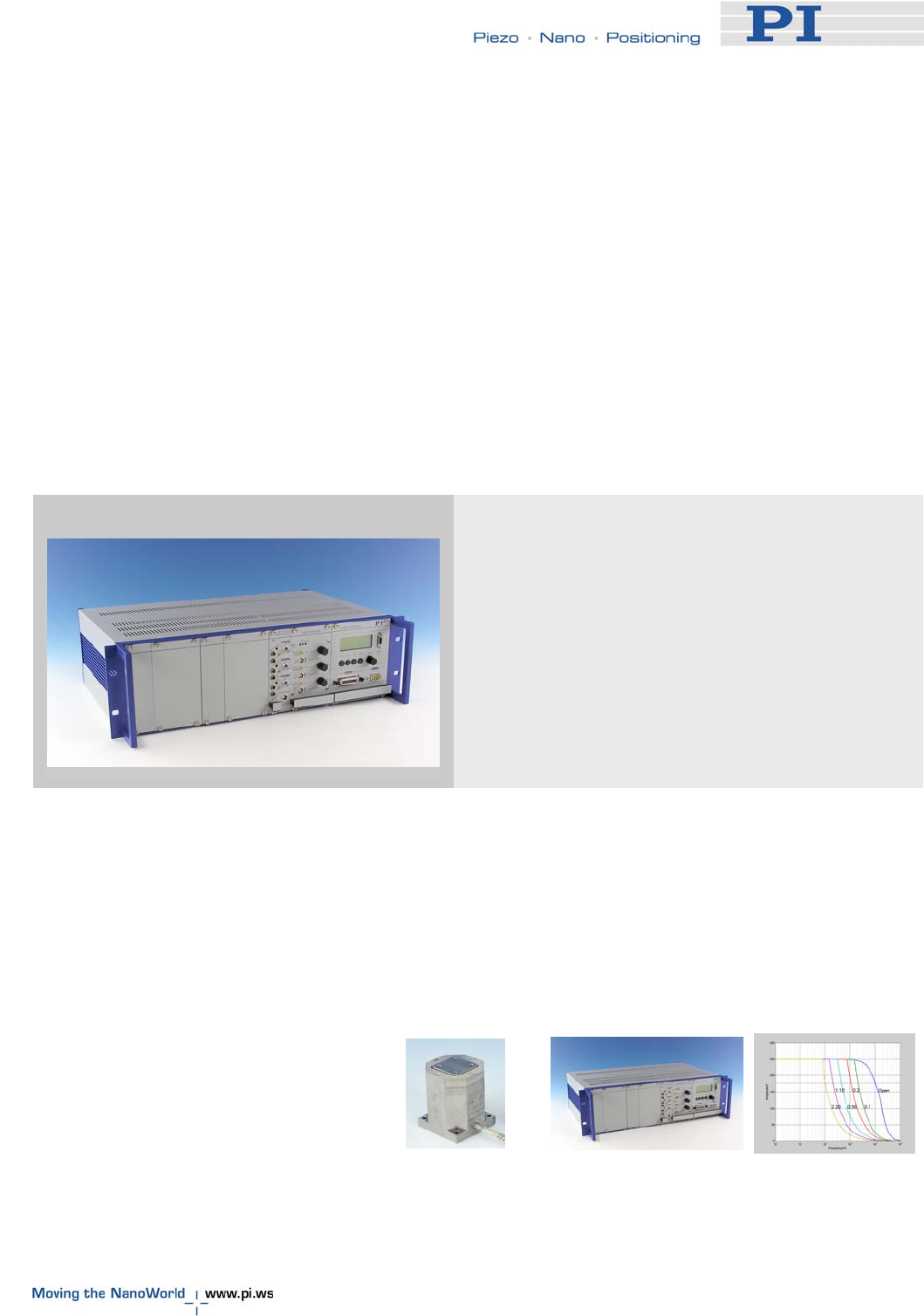
E-536_User_PZ173E122 E-536 PicoCube Piezo Controllers
User Manual: Physik Instrumente E-536 PicoCube Piezo Controller
Open the PDF directly: View PDF ![]() .
.
Page Count: 38
- 1 Introduction
- 1.1 Features
- 1.2 Prescribed Use
- 1.3 Safety Precautions
- 1.4 Model Survey & Additional Products
- 1.5 Optional E-516 Interface and Display Module
- 1.6 Unpacking
- 2 Operation
- 3 Design
- 4 Settings and Adjustments
- 5 Download of the GCS LabVIEW Driver Set for Analog Controllers
- 6 Maintenance
- 7 Troubleshooting
- 8 Technical Data
PZ173E User Manual
E-536 PicoCube® Controller
Release: 1.2.2 Date: 2007-03-29
This document describes the
following product(s):
E-536.3C
PicoCube® Controller, 3 Channels, closed-loop
E-536.30
PicoCube® Controller, 3 Channels, open-loop
E-536.3CH
PicoCube® Controller High-Resolution, 3 Channels,
closed-loop
E-536.30H
PicoCube® Controller High-Resolution , 3 Channels,
open-loop
info@pi.w
© Physik Instrumente (PI) GmbH & Co. KG
Auf der Römerstr. 1 ⋅ 76228 Karlsruhe, Germany
Tel. +49 721 4846-0 ⋅ Fax: +49 721 4846-299
s ⋅ www.pi.ws
Declaration of
Conformity
according to ISO / IEC Guide 22 and EN 45014
Manufacturer: Physik Instrumente (PI)
GmbH & Co. KG
Manufacturer´s
Address: Auf der Römerstrasse 1
D-76228 Karlsruhe, Germany
The manufacturer hereby declares that the product
Product Name: PicoCube® Controller
Model Numbers: E-536
Product Options: all model types
conforms to the following EMC Standards and normative
documents:
Electromagnetic Emission: EN 61000-6-3, EN 55011
Electromagnetic Immunity: EN 61000-6-1
Safety (Low Voltage Directive) : EN 61010-1
August 17, 2006
Karlsruhe, Germany
Dr. Karl Spanner
President

Physik Instrumente (PI) GmbH & Co. KG is the owner of the following company names and
trademarks:
PI®, PicoCube® , Hyperbit™ (U.S. Patent 6,950,050)
Copyright 2007 by Physik Instrumente (PI) GmbH & Co. KG, Karlsruhe, Germany.
The text, photographs and drawings in this manual enjoy copyright protection. With regard
thereto, Physik Instrumente (PI) GmbH & Co. KG reserves all rights. Use of said text,
photographs and drawings is permitted only in part and only upon citation of the source.
First printing 2007-03-29
Document Number PZ173E, Release 1.2.2
E-536_User_PZ173E122_inArbeit.doc
Subject to change without notice. This manual is superseded by any new release. The newest
release is available for download at www.pi.ws.
About this Document
Users of this Manual
This manual is designed to help the reader to install and operate the E-536. It assumes that the
reader has a fundamental understanding of basic electronics and, if applicable, servo and
motion control concepts and the associated safety procedures.
This manual describes the physical specifications and dimensions of the E-536 as well as the
procedures which are required to put the associated motion system into operation.
This document is available as PDF file. Updated releases are available via FTP or email:
contact your PI sales engineer or write info@pi.ws.
Conventions
The notes and symbols used in this manual have the following meanings:
WARNING
Calls attention to a procedure, practice or condition which, if not
correctly performed or adhered to, could result in injury or death.
DANGER
Indicates the presence of high voltage (> 50 V). Calls attention to
a procedure, practice or condition which, if not correctly
performed or adhered to, could result in injury or death.
!
CAUTION
Calls attention to a procedure, practice, or condition which, if not
correctly performed or adhered to, could result in damage to
equipment.
NOTE
Provides additional information or application hints.
Related Documents
The optional interface modules and the software tools which might be delivered with the E-536
are described in their own manuals. All documents are available as PDF files. Updated releases
are available via FTP or email: contact your PI sales engineer or write info@pi.ws.
Only relevant if the E-536 comprises the covered hardware:
E-509_User_PZ77E
E-802_User_PZ113E
E-516_User_PZ102E
Contents
1 Introduction 3
1.1 Features .....................................................................................3
1.2 Prescribed Use...........................................................................4
1.3 Safety Precautions .....................................................................4
1.4 Model Survey & Additional Products ..........................................7
1.5 Optional E-516 Interface and Display Module............................8
1.6 Unpacking ..................................................................................9
2 Operation 10
2.1 Front and Rear Panel Elements ...............................................10
2.2 Modes of Operation..................................................................12
2.2.1 Open Loop and Closed Loop ................................................... 12
2.2.2 Analog Operation ..................................................................... 13
2.2.3 Remote Control via Computer Interface .................................. 14
2.3 Getting Started .........................................................................14
2.3.1 How to Achieve Best Performance .......................................... 14
2.3.2 Line Voltage Connection .......................................................... 15
2.3.3 How to Work with the System .................................................. 16
3 Design 19
3.1 Channels and Axes ..................................................................19
3.2 Block Diagram..........................................................................19
3.3 E-507 HVPZT Piezo Amplifier Module .....................................20
3.4 E-509 Sensor & Position Servo-Control Module ......................21
4 Settings and Adjustments 22
4.1 General ....................................................................................22
4.2 E-536 Closed-Loop Models Only .............................................22
4.2.1 Zero-Point Adjustment ............................................................. 22
4.2.2 Further Procedures .................................................................. 25
5 Download of the GCS LabVIEW Driver Set for
Analog Controllers 26
6 Maintenance 27
6.1 Cleaning ...................................................................................27
6.2 AC Power and Line Power Fuses ............................................27
Contents
7 Troubleshooting 29
8 Technical Data 31
8.1 Operating Limits .......................................................................31
8.2 Specifications ...........................................................................32
8.3 Sensor Monitor LEMO Socket..................................................34
Introduction
1 Introduction
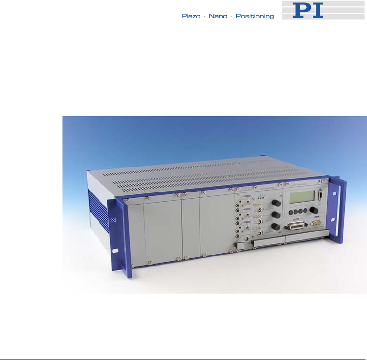
Fig. 1: E-536.3C with E-516 20-bit computer interface and
display upgrade (rightmost module)
1.1 Features
The E-536 is a controller for the P-363 PicoCube® pico-
positioning system providing three ultra-low-noise amplifier
channels for piezo shear actuators. The controller design
meets the special requirements of the high-speed, ultra-high-
performance PicoCube® XY(Z) piezo stages of +/- 250 V for
both static and dynamic applications.
The high-performance E-536.3x can output and sink peak
currents up to 200 mA featuring a small-signal bandwidth of 10
kHz. The E-536.3xH ultra-high-resolution models provide a
position resolution below 0.03 nm at a peak power of 50 W.
Both models are available with or without a servo module for
closed-loop or open-loop operation.
Superior Resolution and High Dynamics
Open-loop position control is ideal for applications where the
fastest response and highest bandwidth and resolution are
essential. Here, commanding and reading the target position in
absolute values is either not required or is handled by external
sensors, as done in AFM applications. Together with the P-363
PicoCube® a resolution of 0.05 nm or better is achieved.
www.pi.ws E-536 PZ173E Release 1.2.2 Page 3

Introduction
1.2 Prescribed Use
Based on their design and realization, E-536 PicoCube®
Controllers are intended to drive capacitive loads, in the present
case, piezoceramic actuators with a voltage range of -250 V to
+250 V. E-536 must not be used for applications other than
stated in this manual, especially not for driving ohmic (resistive)
or inductive loads. E-536s can be operated in closed-loop mode
using capacitive position sensors. Appropriate sensors are
provided by PI and integrated in the mechanics according to the
mechanics product specifications. Other sensors may be used
as position sensors only with permission of PI.
Observe the safety precautions given in this User Manual.
Operation other than instructed in this Manual may affect the
safeguards provided.
E-536s meet the specifications of EN 61010 for safe operation
under normal ambient conditions. See the specifications table
on p. 32 for details.
1.3 Safety Precautions
Carefully read also the documentation of the included software
components and of the mechanics used.
Ignoring the warning notices in the instructions can cause bodily
injury of the user or damage to equipment or loss of warranty.
Note that the E-536 does not contain any user serviceable
parts.
CAUTION—READ INSTRUCTION
Install and operate the E-536 PicoCube® Controller only
when you have read the operating instruction. Keep the
instruction readily available close to the device in a safe
place. When the instruction is lost or has become
unusable, ask the manufacturer for a new copy. Add all
information given by the manufacturer to the instruction,
e.g. supplements or Technical Notes.
DANGER—HAZARDOUS VOLTAGE
The high-voltage amplifiers used by the E-536 may cause
serious or even lethal injury if used improperly. Working
with high-voltage amplifiers requires adequately trained
operating personnel.
www.pi.ws E-536 PZ173E Release 1.2.2 Page 4
Introduction
The E-536 generates voltages between -250 V and +250 V
for driving PicoCube® piezo stages. Never touch any part
that might be connected to the high-voltage output. The
high-voltage output is present on the "PZT Out 1", "PZT
Out 2" and "PZT Out 3" LEMO sockets.
WARNINGS
• LINE VOLTAGE
E-536s need to be installed in such a way that they can
quickly and easily be separated from the line voltage.
Before cleaning the E-536, changing the AC fuses and
removing or installing modules, switch the device off
and disconnect it from the line power.
• INSTALLATION
Procedures which require removing or installing
modules should be carried out by authorized, qualified
personnel only.
! CAUTION
• AIR CIRCULATION
Do not cover the ventilation slots on the top side of the
E-536. The device needs to be installed horizontally with
3 cm air circulation area. Vertical mounting prevents
internal convection. Insufficient air flow will cause
overheating and premature failure.
• REPLACING FUSES
If you change the supply power voltage setting from 115
V to 230 V or vice-versa, you must also replace the 2
line fuses with fuses appropriate for the new voltage.
Both fuses are active and have to be checked if there is
a fault. See “AC Power and Line Power Fuses” p. 27..
• TEMPERATURE
The high voltage output of the E-536 will be deactivated
automatically if the hardware temperature is out of range
(> 75 °C). In this case, the TOfl LED on the front panel
lights up and the piezo stage does no longer move. If an
E-516 interface and display module is present in the E-
536, communication with the device will still be possible,
but move commands are not executed.
After a cooling-down period, at a hardware temperature
of 60 °C, the high-voltage output is reactivated
www.pi.ws E-536 PZ173E Release 1.2.2 Page 5

Introduction
automatically.
To avoid overheating, reduce the operating frequency
and/or the load and/or the ambient temperature.
• CONTROL INPUT
Control Input sockets which are not in use must be
shorted using a jump plug for highest stability of piezo
voltage output and axis position.
• CLOSED CIRCUIT
If your E-536 contains dummy modules: Do not operate
the E-536 when the dummy modules are removed.
Without the dummy module(s), the system will
malfunction because no Control In signal can be feed
into the amplifier module due to the broken circuit.
• SUITABLE ACTUATORS
Only connect PZT actuators designed for operation at -
250 to +250 V (e.g. PicoCube® piezo stages) to the E-
536. Other PZT actuators will be damaged or destroyed
when operated with the E-536.
• CALIBRATION
Calibration should only be done by qualified authorized
personnel after consultation with PI, otherwise internal
configuration data may be destroyed by erroneous
operation.
If you inform PI about your application, your E-536s will
be fully calibrated before being shipped. It is usually not
necessary for you to do anything more than adjust the
zero point before operating the system.
Do not interchange controller (whole devices or
individual modules) and/or piezo stages when they are
matched and calibrated together. Respect the
assignment of the piezo stages to the individual
controller channels, as indicated by the serial numbers
on the labels affixed to the devices. With multi-axis
stages respect the channel/axis assignments indicated
by the cable labeling.
• RESONANT FREQUENCY
Most piezo actuators that can be connected to the E-
536 can be destroyed by uncontrolled oscillation near
the mechanical resonant frequency. If you observe
resonance while configuring your system, switch off
power to the actuators concerned immediately and
check the settings and servo-control parameters.
• SENSOR MONITOR
Do not apply any input voltage to the SENSOR
www.pi.ws E-536 PZ173E Release 1.2.2 Page 6

Introduction
MONITOR socket. This could cause damage to the
electronics.
1.4 Model Survey & Additional Products
E-536 PicoCube® Controllers are available in the following
model types:
Model Type Specifications*
E-536.3C
PicoCube® Controller
3-channel closed-loop version:
3 PZT channels (E-507.336
amplifier module)
3 sensor channels for
capacitive sensors
E-536.30
PicoCube® Controller 3-channel open-loop version:
3 PZT channels (E-507.336
amplifier module)
E-536.3CH
PicoCube® Controller
3-channel closed-loop version:
3 PZT channels high
resolution (E-507.36H
amplifier module)
3 sensor channels for
capacitive sensors
E-536.30H
PicoCube® Controller 3-channel open-loop version:
3 PZT channels high
resolution (E-507.36H
amplifier module)
*The complete specifications can be found in Section 8.2 on page 32.
www.pi.ws E-536 PZ173E Release 1.2.2 Page 7

Introduction
Additional Products
E-500.ACD
CD with
Driver Set for
Analog
Controllers,
available on
request free
of charge
Computer control of an E-536 can be realized
using a DAC-board in a PC to generate the
analog input signal. PI offers a LabVIEW™
driver set which can be used with certain D/A
boards. This driver set is compatible with the PI
General Command Set (GCS) LabVIEW™
driver set available for all newer controllers
from PI. The Analog Controller LabVIEW™
Driver (E-500.ACD) is free of charge, but
requires the LabVIEW™ environment from
National Instruments for operation. The PI
Analog Controller drivers support all D/A
converter boards from National Instruments
that are compatible with DAQmx8.3.
LabVIEW™ compatibility is given from version
7.1 upwards. Connection of a sensor monitor
signal from a sensor module (e.g. E-509) is
required.
The driver set is also available for download
from the PI website (see p. 26).
E-500.HCD
Hyperbit™
Functionality
for Enhanced
System
Resolution
Hyperbit™ Functionality for Enhanced System
Resolution access
PI’s patented Hyperbit™ technology for
providing position resolution higher than that of
the D/A board is in the E-500.ACD driver set.
Activating Hyperbit™ requires purchase of the
password, which can be obtained from PI
under Order No. E-500.HCD.
1.5 Optional E-516 Interface and Display
Module
Optionally, the E-516.i3 3-channel computer interface & display
module with 20-bit DAC, IEEE 488 and RS-232 interfaces can
be integrated in the E-536. If the E-516 was ordered with the E-
536, the complete system comes ready for use. Otherwise the
E-536 should be shipped back to PI for E-516 integration and
system calibration—contact your PI sales engineer or write
info@pi.ws, if you want to upgrade your E-536.
See the E-516 User Manual for hardware description and
operation instructions.
www.pi.ws E-536 PZ173E Release 1.2.2 Page 8

Introduction
1.6 Unpacking
Unpack the E-536 PicoCube® Controller with care. Compare
the contents against the items ordered and against the packing
slip.
The following items should be included:
E-536 PicoCube® Controller
3 x E-692.SMB cables for control signal input
3763 line cord
E-536 User Manual (this document, PZ173E)
E500T0011 Technical Note for GCS LabVIEW driver
set
with E-536.3C and E-536.3CH closed-loop versions only:
D-893.32 sensor monitor cable
The purpose of this cable is simply to split up the
SENSOR MONITOR output signal (6-pin LEMO) to three
separate BNC connectors. The cable is also specially
designed for the low-noise feature. The BNC connectors
are each labeled with the channel number.
with E-536.3C and E-536.3CH closed-loop versions only:
E-509 User Manual (PZ77E) and E-802 User Manual
(PZ113E)
Inspect the contents for signs of damage. If parts are missing or
you notice signs of damage, contact PI immediately.
Save all packing materials in the event the product need to be
shipped elsewhere.
NOTE
A Sub-D-to-LEMO adapter cable for the connection of the
mechanics comes either with the PicoCube® or can be
ordered separately, order# P-893.1DPL.
www.pi.ws E-536 PZ173E Release 1.2.2 Page 9
Operation
2 Operation
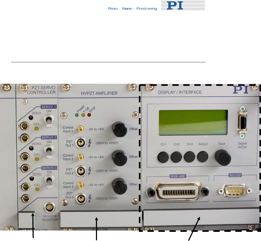
2.1 Front and Rear Panel Elements
E-509 Sensor & Position
Servo-Control Module, with
E-536 closed-loop models only
E-507.336 HVPZT Amplifier
Module
(identical elements on
E-507.36H)
Optional equipment:
E-516.i3 Computer Interface and Display Module
Fig. 2: Front panel of E-536.3C 3-channel, closed-loop
PicoCube® Controller
Common elements:
Power LED Power on/off indicator
T Ofl LED Lights up if the temperature on the
amplifier heat sink exceeds 75 °C. In
this case, the amplifier is automatically
deactivated and activated again when
the temperature falls below 60 °C.
Error LED Provided for future applications
www.pi.ws E-536 PZ173E Release 1.2.2 Page 10

Operation
SENSOR MONITOR closed-loop models only; LEMO
connector for reading out the sensor
input signal (0 to 10 V), for pinout see
p. 34
! CAUTION
Do not apply any input voltage to the SENSOR MONITOR
socket. This could cause damage to the electronics.
Elements provided once per channel:
T LEMO socket for sensor Target
connector (E-536 closed-loop models
only)
P LEMO socket for sensor Probe
connector (E-536 closed-loop models
only)
ZERO This potentiometer shifts the output of
the sensor processing circuitry, see
p. 22 for details. (E-536 closed-loop
models only)
OFL LED Lights up if the output voltage would be
outside the nominal output voltage
range of the controller (E-536 closed-
loop models only)
SERVO ON/OFF Switch for changing between open-loop
(off) and closed-loop mode (on) (E-536
closed-loop models only)
Control Input SMB connector for external analog
control signal, -5 V to +5 V for open-loop
operation, 0 V to +10 V for closed-loop
operation (see also p. 13)
PZT Out LEMO socket for high-voltage output,
-250 V to +250 V
Offset 10-turn DC-offset potentiometer for
analog control
E-516 Computer Interface and Display Module:
Framed with dashed line in Fig. 2. See the E-516 User Manual
for a description of the front panel elements and operation
instructions.
www.pi.ws E-536 PZ173E Release 1.2.2 Page 11
Operation
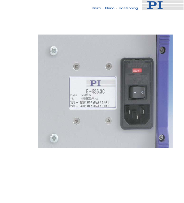
Fig. 3: Rear panel elements of E-536, without calibration label
The line voltage connection and the integrated fuse carrier are
described in detail in Section 6.2 on p. 27.
2.2 Modes of Operation
2.2.1 Open Loop and Closed Loop
Open loop: All E-536 versions can be operated in
open-loop mode. Open-loop operation means that any
control input done by the user determines the output
voltage for the moving axis directly.
Closed loop: E-536.3C and E-536.3CH models can
also be operated in closed-loop mode. Closed-loop
operation means that any control input done by the user
determines a target position for the moving axis. The
output voltage required to reach this target position is
calculated internally by the servo-loop, based on the
given target and the feedback of the position sensors.
For E-536 closed-loop models, the servo-control state can be
set using the SERVO toggle switches on the front panel. When
these devices are upgraded with an E-516 computer interface
and display module, the servo state can also be set via
www.pi.ws E-536 PZ173E Release 1.2.2 Page 12

Operation
command from the host PC (see Section 2.2.3 and E-516 User
Manual for details). In this case, all SERVO toggle switches on
the front panel must be set to OFF.
2.2.2 Analog Operation
All E-536 versions can be operated by an analog control signal.
In open-loop mode, this signal must be in the voltage range of
-5 to +5 V. In closed-loop mode a voltage range of 0 to +10 V is
required. The analog control signal can be provided as follows:
External signal source: Depending on the servo
state, the output voltage or the target position of a
moving axis is set by a DC voltage applied to the Control
Input SMB socket.
Computer control of an E-536 can also be realized using
a DAC-board in a PC to generate the analog input signal.
PI offers a LabVIEW™ driver set which can be used with
certain D/A boards. This driver set is compatible with the
PI General Command Set (GCS) LabVIEW™ driver set
available for all newer controllers from PI. In addition, PI’s
patented Hyperbit™ technology for providing position
resolution higher than that of the D/A board is in the E-
500.ACD driver set. See Sections 1.4, p. 7 and 5, p. 26,
for information on PI support
Offset potentiometer: Depending on the servo state,
the output voltage or the target position of a moving axis
can be set using the 10-turn offset potentiometer on the
E-536 front panel. The offset potentiometer can also be
used to add an offset to the signal applied on the Control
Input socket.
If a constant offset (e.g. 0 V) is required, make sure the
knob stays at the appropriate position.
NOTE
For closed-loop operation, the controller is calibrated in
such a way that any given voltage in the input range
corresponds to the proportional displacement of the
actuator in its nominal travel range (regardless of any non-
linearities in the actual voltage required to obtain that
displacement).
www.pi.ws E-536 PZ173E Release 1.2.2 Page 13

Operation
2.2.3 Remote Control via Computer Interface
E-536 models upgraded with an E-516 computer interface and
display module can be controlled from a host computer. During
remote control via the RS-232 or IEEE488 PC interface, any
analog control input voltages and DC-offset settings described
in Section 2.2.2 are ignored, and for closed-loop models all
SERVO switches on the front panel must be set to OFF.
Remote control is also referred to as Online mode, while the
analog operation described in Section 2.2.2 is also referred to
as Offline mode. See the E-516 User Manual for details.
2.3 Getting Started
DANGER
The high-voltage amplifiers used by the E-536 may cause
serious or even lethal injury if used improperly. Working
with high-voltage amplifiers requires adequately trained
operating personnel.
The E-536 generates voltages between -250 V and +250 V
for driving PicoCube® piezo stages. Never touch any part
that might be connected to the high-voltage output. The
high-voltage output is present on the "PZT Out 1", "PZT
Out 2" and "PZT Out 3" LEMO sockets.
!
CAUTION
Most piezo actuators that can be connected to the E-536
can be destroyed by uncontrolled oscillation near the
mechanical resonant frequency. If you observe resonance
while configuring your system, switch off power to the
actuators concerned immediately and check the settings
and servo-control parameters.
2.3.1 How to Achieve Best Performance
Follow the instructions and recommendations below to achieve
best performance of the system.
Calibrated system:
Do not interchange controller (whole devices or individual
modules) and/or actuators/stages when they are matched
www.pi.ws E-536 PZ173E Release 1.2.2 Page 14

Operation
and calibrated together. Respect the assignment of the
actuators/stages to the individual controller channels, as
indicated by the serial numbers on the labels affixed to
the devices. With multi-axis stages respect the
channel/axis assignments indicated by the cable labeling.
Voltage and position stability:
For highest stability of piezo voltage output and axis
position, the "Control Input" sockets must be closed with
low impedance (use the E-692.SMB cables which come
with the E-536 to connect a control signal). Control input
sockets which are not in use must be shorted using a
jump plug.
A higher noise level in closed-loop operation (servo on)
depends only on the capacitive sensor and the servo
bandwidth.
Measuring setup:
Carefully design your measuring setup to avoid
interferences and magnetic fields caused by external
signal sources like function generators, measuring
devices like oscilloscopes and any connecting cables.
Amplifier bandwidth:
For highest amplifier bandwidth (up to 10 kHz in small
signal operation), the slew rate of the servo-control
module must be set to the maximum value. A slew rate
value optimized for closed-loop operation would also be
active in open-loop and hence significantly limit the
bandwidth.
Control signal:
The voltage range of the analog control signals connected
to the Control Input SMB sockets differs depending on the
servo state:
open-loop operation (servo off): -5 V to +5 V
closed-loop operation (servo on): 0 V to +10 V
2.3.2 Line Voltage Connection
WARNING
E-536s need to be installed in such a way that they can
quickly and easily be separated from the line voltage.
www.pi.ws E-536 PZ173E Release 1.2.2 Page 15

Operation
Unless you request otherwise, upon delivery the E-536 will be
set up for the voltage predominant in your country, either
115 V ~ / 45VA / 0.4A / 50-60 Hz
or
230 V ~ / 45VA / 0.2A / 50-60 Hz
To adapt the E-536 to a different line voltage, the line power
fuses must be replaced. See p. 27 for instructions and for the
required fuse types.
Connect the controller (rear panel) to an appropriate power
outlet using the line cord which comes with the E-536.
2.3.3 How to Work with the System
!
CAUTION
Do not cover the ventilation slots on the top side of the E-
536. The device needs to be installed horizontally with
3 cm air circulation area. Vertical mounting prevents
internal convection. Insufficient air flow will cause
overheating and premature failure.
!
CAUTION
The high voltage output of the E-536 will be deactivated
automatically if the hardware temperature is out of range
(> 75 °C). In this case, the TOfl LED on the front panel
lights up and the piezo stage does no longer move. If an E-
516 interface and display module is present in the E-536,
communication with the device will still be possible, but
move commands are not executed.
After a cooling-down period, at a hardware temperature of
60 °C, the high voltage output is reactivated automatically.
To avoid overheating, reduce the operating frequency
and/or the load and/or the ambient temperature.
The following instructions refer to the analog operation of the
system. If your E-536 is upgraded with an E-516 computer
interface and display module and you want to control the
system via the computer interface, only perform steps 1 to 3 of
the instruction below and then go on working with the system as
www.pi.ws E-536 PZ173E Release 1.2.2 Page 16

Operation
described in the E-516 User Manual.
1 Make sure that the E-536 is connected to line power
but powered down (see Section 2.3.2)—line cord
socket and power switch are at the rear panel.
2 Connect the piezo stage to the E-536—when the piezo
stage is equipped with a Sub-D connector, use a Sub-
D-to-LEMO adapter cable (# P-893.1DPL). Respect the
channel/axis assignment given by the label on the
controller rear panel.
2.1 Connect the cables labeled "X-AXIS", "Y-AXIS"
and "Z-AXIS" to the PZT Out sockets.
2.2 Closed-loop systems only: Connect the sensor
cables labeled "Target" to the T sockets and the
cables labeled "Probe" to the P sockets. Make
sure that the "Target" and "Probe" cables are not
interchanged— if you switch "Probe" and
"Target", the sensor system will work but results
will not be as accurate as specified.
3 Optionally: If you want to read out the sensor monitor
signal, connect appropriate electronics to the SENSOR
MONITOR socket using the D-893.32 sensor monitor
cable.
4 Turn all Offset potentiometers CCW (zero offset) to
avoid jumps of the mechanics when the controller is
powered on.
5 With E-536.3Cand E-536.3CH closed-loop models
only: Set the desired servo-control state using the
SERVO toggle switches on the front panel.
6 If you want to operate the E-536 by external analog
control signals, connect suitable signal sources to the
Control Input SMB sockets. Use the E-692.SMB cables
which come with the E-536, but do not yet apply any
voltage to these lines.
The E-536 accepts control input signals in the following
voltage ranges:
-5 V to +5 V are required for open-loop operation
(servo off).
0 V to +10 V are required for closed-loop operation
(servo on).
www.pi.ws E-536 PZ173E Release 1.2.2 Page 17

Operation
!
CAUTION
Control Input sockets which are not in use must be shorted
using a jump plug for highest stability of piezo voltage
output and axis position.
7 Switch the E-536 on. Now the green Power LED on the
amplifier module lights up.
8 Command motion for the axes of the piezo stage by
turning the Offset potentiometer
applying an external analog control signal in the
appropriate input range
using a combination of Offset potentiometer
setting and external analog control signal.
When an E-516 interface and display module is
present in the system, watch the current voltage and
position values on the display to check if the system
operates properly.
When one ore more OFL LEDS should light up, the
amplifier output is being clipped at one of its limits and
the current piezo displacement no longer complies with
the control signal. Follow the instructions for zero-point
adjustment on p. 22 to re-adjust the system.
www.pi.ws E-536 PZ173E Release 1.2.2 Page 18

Design
3 Design
3.1 Channels and Axes
Every moving axis of the mechanics is assigned to one PZT
channel (amplifier output channel) and one sensor channel of
the E-536. Due to this “one-axis/one-sensor/one-amplifier”
design, the terms "axis" and "channel" can be used
synonymously.
The assignment of axes and channels is done prior to shipment
during calibration at PI and stated by a label on the E-536 rear
panel.
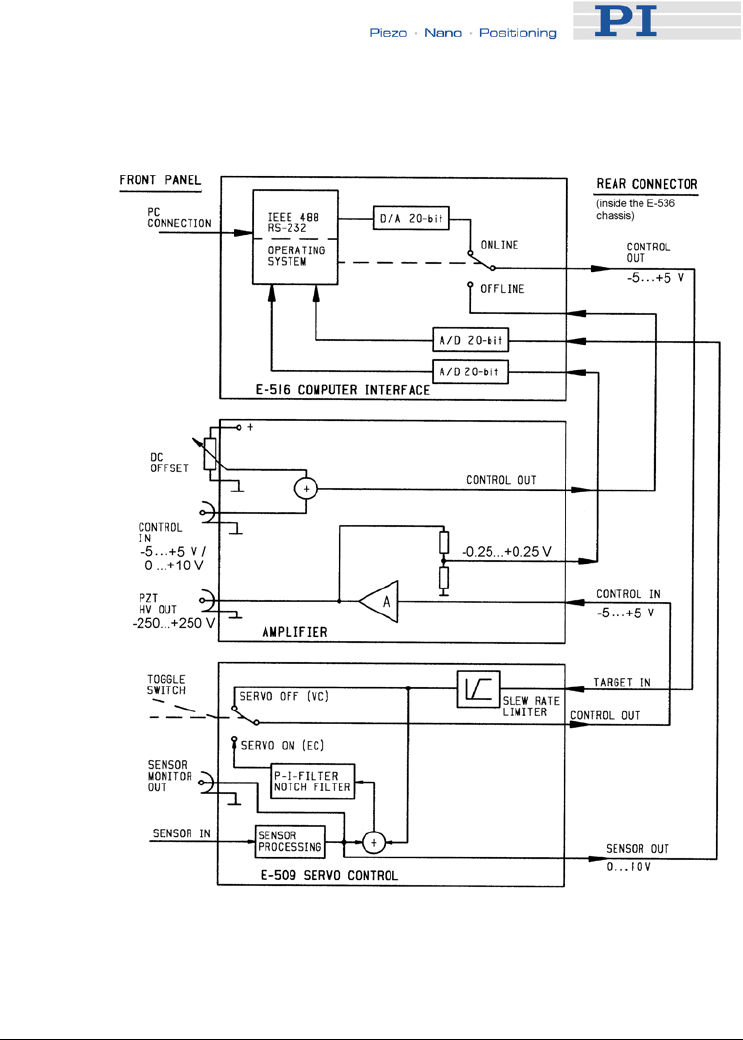
3.2 Block Diagram
The block diagram below shows the signal path for E-536
closed-loop versions upgraded with an E-516 interface and
display module. E-536 open-loop versions and models without
E-516 module are equipped with dummy modules instead:
E-595.00 Replaces E-509.Cxx sensor modules
E-596.10 Replaces the E-516 computer interface
and display module
The purpose of these dummies is to complete the internal
circuitry and the front panel of the chassis.
! CAUTION
If your E-536 contains dummy modules: Do not operate the
E-536 when the dummy modules are removed. Without the
dummy module(s), the system will malfunction because no
Control In signal can be fed into the amplifier module due
to the broken circuit.
www.pi.ws E-536 PZ173E Release 1.2.2 Page 19
Design
Fig. 4: Signal path for E-536 closed-loop versions with E-516
interface and display module
3.3 E-507 HVPZT Piezo Amplifier Module
E-507 HVPZT Amplifier Modules generate drive voltage for
high-voltage PZTs. The output ranges from -250 to +250 V.
One terminal of the HV output is held at system ground. The
modules can be used for static and dynamic operations
providing a peak current of 200 mA for < 3 ms (E-507.336) or
100 mA for < 1ms (E-507.36H) to allow fast PZT displacement
changes. The modules are short-circuit and open-circuit
protected.
The output voltage can be controlled by an analog input
signal applied to the front-panel Control Input line, in
combination with the DC-offset potentiometer, or by the
www.pi.ws E-536 PZ173E Release 1.2.2 Page 20

Design
optional E-516 computer interface and display module. In
closed-loop operation, the output voltage is controlled by the
E-509.Cxx sensor & position servo-control module. See
Section 2.2 on p. 12 for control details and Section 3.2 on
p. 19 for the signal path.
3.4 E-509 Sensor & Position Servo-
Control Module
The E-509 sensor & position servo-control module is part of the
E-536.3C and E-536.3CH closed-loop models. Its servo-loop
logic compares the control voltage input (target) and the sensor
signal (current position) to generate the amplifier control signal
using an analog proportional-integral (P-I) algorithm. Thus it
compensates for drift and hysteresis of the PZT actuators. Note
that control signal generation, slew rate limitation, notch filter
and servo-control loop are all implemented on the E-802.52, a
small PCB submodule which is implemented on the E-509 once
per channel.
For hardware details and calibration procedures, see the User
Manuals for the E-509 and E-802.52 modules.
www.pi.ws E-536 PZ173E Release 1.2.2 Page 21

Settings and Adjustments
4 Settings and
Adjustments
4.1 General
All basic calibration adjustments are done in PI lab before
shipment. The PZT system is delivered ready for operation.
When system components are to be exchanged or modified,
contact your Physik Instrumente sales engineer or write to
info@pi.ws.
4.2 E-536 Closed-Loop Models Only
4.2.1 Zero-Point Adjustment
The zero points of the individual channels have to be realigned
from time to time to compensate for temperature changes.
Proper zero-point adjustment ensures that the full output
voltage swing of the amplifier can be used without reaching the
output voltage limits of the amplifier and causing overflow
conditions. If an overflow condition occurs (OFL LED lights up
for the channel), it can often be prevented by re-adjusting the
ZERO point.
The zero-point for each channel is adjusted with the ZERO
potentiometer, accessible through a labeled hole in the E-536
front panel (see Fig. 2 on p. 10). This potentiometer shifts the
output of the sensor processing circuitry and hence the values
on the "Sensor out," "Monitor out" and servo-loop sensor-input
lines (see Fig. 4 on p. 20).
When an E-516 computer interface and display module is
present in your E-536, at first decide whether you want to
perform the zero-point adjustment in computer-controlled mode
(online) or in analog mode (offline). Online and offline operation
must not be mixed during calibration. If you choose offline
operation, make sure that the E-516 computer interface module
is set to "offline". The steps listed below describe offline
operation—if you choose online operation, use computer
commands in place of the analog control voltage and DC-offset
to command voltages and position (you do not need an external
voltage source for computer-controlled calibration).
www.pi.ws E-536 PZ173E Release 1.2.2 Page 22
Settings and Adjustments
Equipment needed:
For zero-point adjustment in analog (offline) operation an
adjustable voltage source is needed which must be able to
output
-5 to +5 V and
0 V to +10 V.
If an E-516 interface and display module is present in the
system, zero-point adjustment can be performed without
additional equipment. Otherwise, a precision voltmeter is
required in addition.
WARNING
Be careful when connecting the voltmeter to the PZT Out
socket during system operation. Voltages between -250 V
and +250 V can be present on the "PZT Out 1", "PZT Out
2" and "PZT Out 3" LEMO sockets.
How to perform zero-point adjustment of one channel in analog
operation:
1 Before powering up the system:
1.1 Make sure the PZT actuator is mounted in the
same way and with the same load as during
normal operations in the application. Respect the
channel/axis assignment given by the label on the
controller rear panel.
1.2 Make sure that the external analog control signal
is 0 V.
1.3 Set the SERVO toggle switch on the front panel
to OFF.
1.4 If no E-516 display module is installed, connect a
voltmeter to the SENSOR MONITOR socket and,
if present, a second voltmeter to the PZT Out
socket in parallel with the PZT actuator.
2 Power up the system. If an E-516 is present, make
sure that it is consistent with analog (offline) operation
and "servo OFF" setting.
3 Turn the Offset potentiometer full clockwise and than
back full counterclockwise (0 V) to exercise the
appropriate axis of the mechanics.
4 Adjust the ZERO potentiometer so that a sensor-
monitor signal of 5 V is measured by the voltmeter on
www.pi.ws E-536 PZ173E Release 1.2.2 Page 23

Settings and Adjustments
the SENSOR MONITOR socket. If present, you can
alternatively read the display of the E-516 module
where the position must be approx. half the nominal
expansion of the axis. The zero adjustment is now
close enough to allow switching on servo-control.
5 Switch the channel to closed-loop (SERVO ON).
NOTE
The axis should now make a jump from the mid position to
the negative limit of its travel range because the expected
range of the analog control signal now is 0 to +10 V
(instead of the -5 to +5 V expected in open-loop operation).
Set the external analog control signal to 5 V to get back to
the axis' mid position.
6 If not already done so, connect the voltmeter to the
PZT Out socket in parallel with the PZT actuator.
7 Again using the ZERO potentiometer, adjust the PZT
output voltage to approx. 0 V.
The zero-point setting is now close enough to allow
checking of the PZT output range.
8 Check the PZT output range by applying a voltage to
the Control Input socket which goes from
0 V to +10 V
and watch the voltage at the PZT Out socket in parallel
with the PZT actuator.
a) If the output voltage ranges from -250 V to
+250 V, then zero-point adjustment is finished.
b) If the output voltage range differs from -250 V to
+250 V, the zero point should be shifted so that
the PZT-output voltage range is in the center of
the amplifier output range. For this purpose,
return the control input to the value which
corresponds to the mid position (+5 V) and repeat
step 7 adjusting the PZT output voltage to a
slightly different value.
www.pi.ws E-536 PZ173E Release 1.2.2 Page 24

Settings and Adjustments
4.2.2 Further Procedures
All other calibration procedures—static gain adjustment1 and
dynamic calibration2—require special equipment and should
only be done by qualified personnel and are required only in
special circumstances. For details regarding those procedures,
see the user manuals for the E-509 sensor & position servo-
control module and for the E-802.52 submodule which is
located on the E-509.
1 The objective of static gain adjustment is to ensure that the actuator
expands to its nominal expansion in "positive" direction when an appropriate
control signal input is applied (with DC-offset disabled).
2 Dynamic calibration optimizes step response and suppresses resonance,
overshoot, and oscillation.
www.pi.ws E-536 PZ173E Release 1.2.2 Page 25

Download of the GCS LabVIEW Driver Set for Analog Controllers
5 Download of the GCS
LabVIEW Driver Set for
Analog Controllers
Updated releases of GCS LabVIEW drivers for analog
controllers from PI and the corresponding manuals are
available for download at www.pi.ws. While the manuals are
freely accessible, you need a password for the software
download. This password is provided in a Technical Note
delivered with the controller (E500T0011).
To download from the PI Website, proceed as follows:
9 On the www.pi.ws front page, click on
"Download/Support" in the "Service" section on the left
10 On the "Download/Support" page, click on "Manuals
and Software"
11 On the "PI Download Server" page, enter the
Username and the Password which are provided in the
separate Technical Note and click on "Login"
12 Click on "Download" in the navigation bar across the
top
13 Click on the "General Software" category
14 Click on "Analog GCS LabVIEW drivers"
15 Click on "Release" (if you click on "Documents" you will
get the latest manuals)
16 Click the "Download" button
www.pi.ws E-536 PZ173E Release 1.2.2 Page 26

Maintenance
6 Maintenance
WARNING
Before cleaning the E-536, changing the AC fuses and
removing or installing modules, switch the device off and
disconnect it from the line power.
6.1 Cleaning
The housing surfaces of the E-536 can be cleaned using mild
detergents or disinfectant solutions. Organic solvents must not
be used.
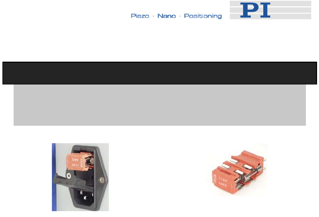
6.2 AC Power and Line Power Fuses
Unless you request otherwise, the unit will be set up for the
power predominant in your country. New line power fuses are
required when changing the supply voltage.
To access the line power fuses, proceed as follows:
1 Switch the E-536 off and remove the line cord.
2 Wait one minute to be sure that all electric circuits are
discharged completely.
3 Pry open the door that covers the fuse carrier
(see Fig. 5) and pry out the fuse carrier.
4 Be sure to replace both fuses with fuses of the type
appropriate for the new voltage:
230 VAC to 240 VAC 0.8 A, slow blow
115 VAC to 240 VAC 1.6 A, slow blow
5 Rotate the fuse carrier so that the valid voltage setting
(115 V or 230 V) can be seen through the window
when the door is closed.
6 Reinstall the carrier and close the door.
www.pi.ws E-536 PZ173E Release 1.2.2 Page 27
Maintenance
!
CAUTION
Both fuses are active and have to be checked if there is a
fault.
Fig. 5: Fuse location on the rear panel and in the carrier (1 of 2
fuses visible)
www.pi.ws E-536 PZ173E Release 1.2.2 Page 28

Troubleshooting
7 Troubleshooting
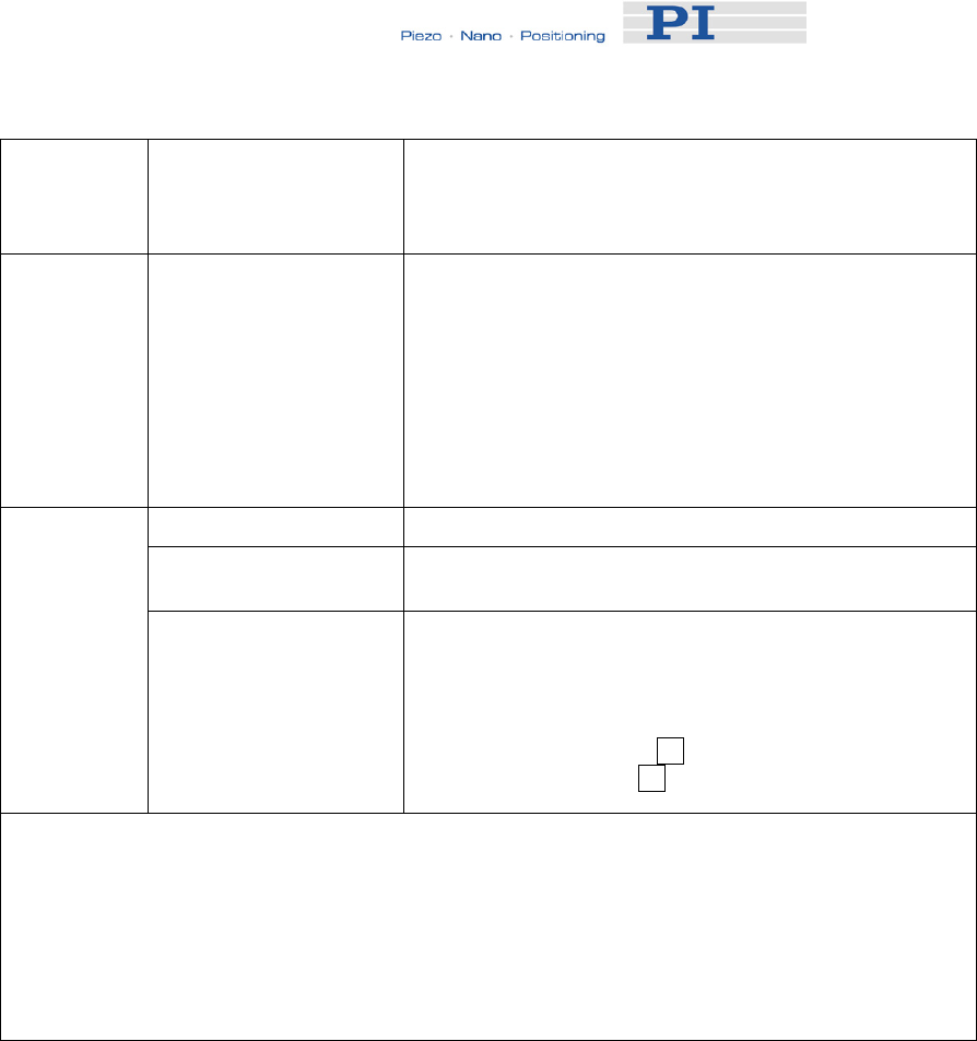
Problem Possible Causes Solutions
Cable not connected or
connected to wrong
connector (if adapter
cable is used)
Check the connecting cable.
Adapter cable is
defective
Connect the stage to a different adaptor cable to test its
function. Do no longer use the defective cable.
Stage or stage cable is
defective
Contact your Physik Instrumente sales engineer or write
info@pi.ws. Do no longer use the defective stage.
The high voltage output
is deactivated.
The high voltage output of the E-536 will be deactivated
automatically if the hardware temperature is out of range
(> 75 °C). In this case, the TOfl LED on the front panel
lights up and the piezo stage does no longer move. If an
E-516 interface and display module is present in the E-
536, communication with the device will still be possible,
but move commands are not executed.
Wait a few minutes to let the device cool down. If the TOfl
LED goes out, the high voltages output is activated again,
otherwise the temperature is still out of range. To avoid
overheating, reduce the operating frequency and/or the
load and/or the ambient temperature. Do not cover the
ventilation slots on the top side of the E-536. The device
needs to be installed horizontally with 3 cm air circulation
area. Vertical mounting prevents internal convection.
Insufficient air flow will cause overheating and premature
failure
Remote control via E-516: Note that the wave generator
output will continue even if the high voltage output is
deactivated, i.e. if a certain number of output cycles was
set, the output may be already finished when the high
voltage output is reactivated. When using the wave
generator, it is recommended to reduce the frequency
and/or the amplitude and/or the output duration to avoid
overheating.
Broken circuit If your E-536 contains dummy modules: Do not operate
the E-536 when the dummy modules are removed.
Check if all dummy modules are installed properly.
Without the dummy module(s), the system will
malfunction because no Control In signal can be feed into
the amplifier module due to the broken circuit. See p. 19
for more information about the signal path.
Stage does
not move
Wrong signal applied to
the Control Input SMB
socket
In open-loop mode, the external signal source used must
provide a voltage range of -5 to +5 V. In closed-loop
mode a voltage range of 0 to +10 V is required.
www.pi.ws E-536 PZ173E Release 1.2.2 Page 29
Troubleshooting
OFL LED
lights up
Overflow condition: The
full output voltage swing
of the amplifier can not
be used.
The amplifier output is being clipped at one of its limits
and the current piezo displacement no longer complies
with the control signal. Follow the instructions for zero-
point adjustment on p. 22 to re-adjust the system.
Nonsatisfying
voltage and
position
stability
"Control Input" sockets
not closed; servo on
For highest stability of piezo voltage output and axis
position, the "Control Input" sockets must be closed with
low impedance (use the E-692.SMB cables which come
with the E-536 to connect a control signal). Control input
sockets which are not in use must be shorted using a
jump plug.
A higher noise level in closed-loop operation (servo on)
depends only on the capacitive sensor and the servo
bandwidth.
Wrong axis commanded Check if commanded axis is that of the desired stage.
Another program still
uses the PCI interface
Close the other program.
Remote
control via E-
516 fails
Specific software has
problems with operating
system.
Compare if another software is running, e.g. a terminal or
development environment. You can, for example, test the
communication by simply starting a terminal program,
e.g. WinTerm32, and entering commands like *IDN? or
HLP?. Note that the commands are transferred as
terminated by a line feed LF character. The command is
executed only after the LF is received.
Still problems? Please call your PI representative and know the following about your system:
Product codes and serial numbers of all used products
Current firmware version of the controller
Software version of driver or host software
Operating system
www.pi.ws E-536 PZ173E Release 1.2.2 Page 30
Technical Data
8 Technical Data
8.1 Operating Limits
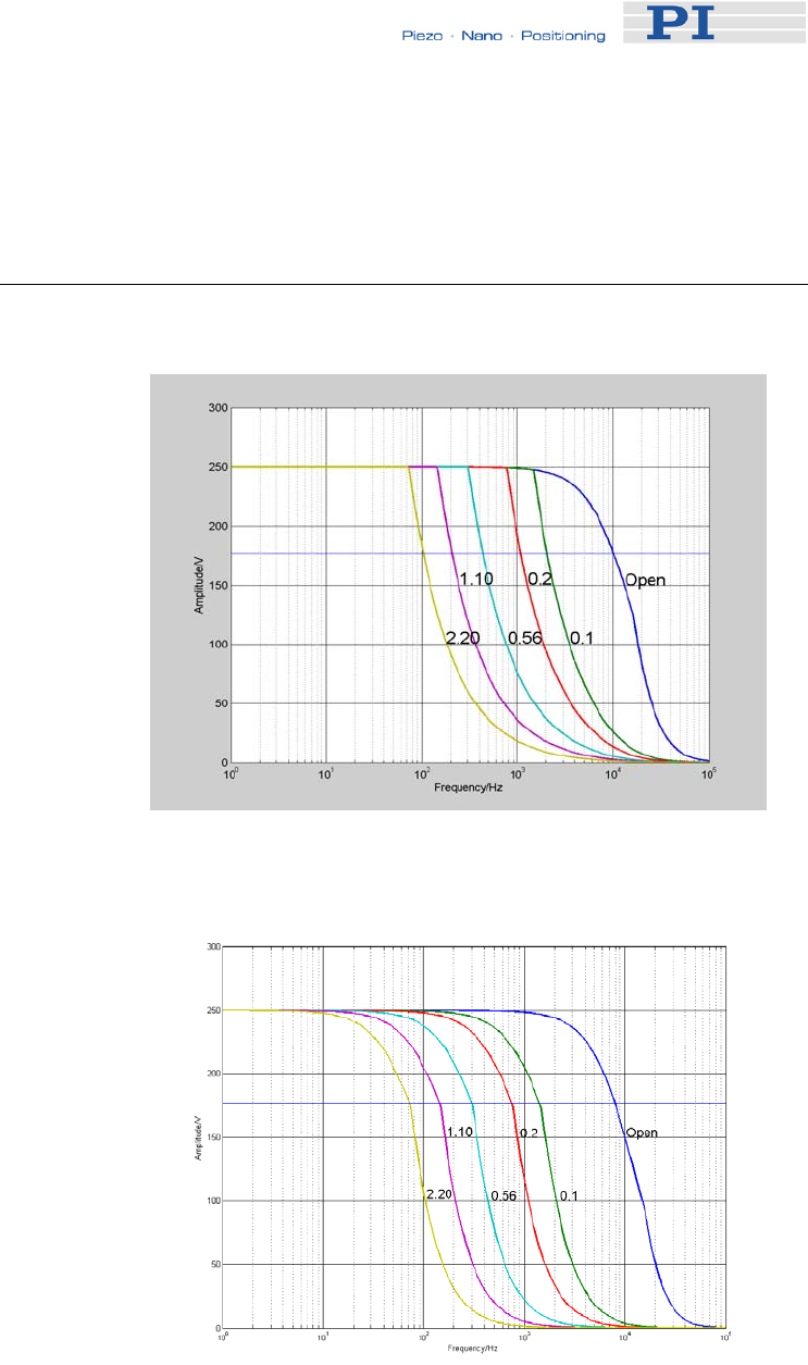
Fig. 6: E-536.3x: Operating limits with various PZT loads.
Values shown are capacitance in μF, measured in actual
PZT
Fig. 7: E-536.3xH: Operating limits with various PZT loads.
Values shown are capacitance in μF
The small-signal capacitance of P-363 PicoCube® piezo stages
is 70 nF, the large-signal value is 0.1 µF.
www.pi.ws E-536 PZ173E Release 1.2.2 Page 31

Technical Data
8.2 Specifications
E-536.3C / E-536.30 E-536.3CH / E-536.30H
Function Power amplifier & servo-
controller for P-363
PicoCube®
Power amplifier & servo-
controller for P-363
PicoCube®
Amplifier
Output voltage -250 to +250 -250 to +250
Amplifier channels 3 3
Average output power
per channel
10 W, limited by
temperature sensor
6 W, limited by
temperature sensor
Peak output power per
channel,
<·3·ms
100 W 50 W
Average current 30 mA 15 mA
Peak current per
channel, < 3 ms
200 mA 100 mA
Amplifier bandwidth,
small signal
10 kHz 2 kHz
Amplifier bandwidth,
large signal, @ 100 nF
0.2 kHz 0.125 kHz
Ripple, noise
0 to 100 kHz
0.8 mVRMS
< 5 mVP-P (100 nF)
0.5 mVRMS
< 3 mVP-P (100 nF)
Current limitation Short-circuit-proof Short-circuit-proof
Voltage gain +50 +50
Input impedance 100 kΩ 100 kΩ
Sensor*
Servo characteristics Analog proportional-integral
(P-I) algorithm with notch
filter
Analog proportional-
integral (P-I) algorithm with
notch filter
Sensor type capacitive sensors capacitive sensors
Sensor channels 3 / - 3 / -
Sensor bandwidth 1.5 kHz 1.5 kHz
Sensor Monitor output 0 to +10 0 to +10
Interfaces and
operation
PZT output sockets LEMO
EGG.0B.701.CJL.1173
LEMO
EGG.0B.701.CJL.1173w
Sensor target and probe
sockets
LEMO EPL.00.250.NTD LEMO EPL.00.250.NTD
Control Input sockets SMB SMB
Sensor Monitor socket LEMO
FGG.0B.306.CLAD56
LEMO
FGG.0B.306.CLAD56
Control input voltage Servo off:-5 to +5
Servo on: 0 to +10
Servo off:-5 to +5
Servo on: 0 to +10
www.pi.ws E-536 PZ173E Release 1.2.2 Page 32
Technical Data
DC Offset 0 to 100% with 10-turn front
-
panel potentiometer
0 to 100% with 10-turn
front-panel potentiometer
Miscellaneous
Operating voltage 115 VAC / 50-60 Hz or
230 VAC / 50-60 Hz
115 VAC / 50-60 Hz or
230 VAC / 50-60 Hz
Mass 8.1 kg / 7.8 (with E-516
module)
8.1 kg / 7.8 (with E-516
module)
Dimensions 450 x 132 x 296 mm +
handles
450 x 132 x 296 mm +
handles
*only E-536.3Cx with capacitive sensors
Interfaces / communication: RS-232 and IEEE 488 (GPIB) (with
optional E-516 computer interface and display module only)
Operating temperature range: +5 °C to +50 °C (over 40 °C, max. av.
power derated 10%), high-voltage output is automatically deactivated
if temperature is too high by internal temperature sensor (75 °C max.)
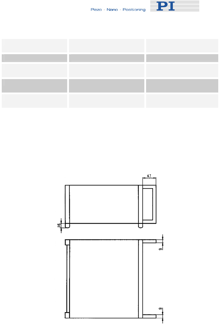
Fig. 8: Dimensions of the handles on the E-536 housing, in mm
www.pi.ws E-536 PZ173E Release 1.2.2 Page 33

Technical Data
8.3 Sensor Monitor LEMO Socket
LEMO Connector (FGG.0B.306.CLAD56), 6-pin
pin 1 ch1+
pin 2 ch1-
pin 3 ch2+
pin 4 ch2-
pin 5 ch3+
pin 6 ch3-
shield: GND
The E-536.3C and E-536.3CH closed-loop models come
with the D-893.32 Sensor-Monitor cable (2 m). The purpose
of this cable is simply to split up the SENSOR MONITOR
output signal (6-pin LEMO) to three separate BNC
connectors. The BNC connectors are each labeled with the
channel number.
www.pi.ws E-536 PZ173E Release 1.2.2 Page 34
