Physik Instrumente N 216 User Manual N216T0013E110
N-216_UserManual_N216T0013E110 N-216 NEXLINE® Linear Actuator
User Manual: Physik Instrumente N-216 NEXLINE® Linear Actuator
Open the PDF directly: View PDF ![]() .
.
Page Count: 33
- 1 General Information
- 2 Product Description
- 3 Unpacking
- 4 Installation
- 5 Start-Up and Operation
- 6 Maintenance
- 7 Troubleshooting
- 8 Customer Service
- 9 Technical Data
- 10 Old Equipment Disposal
- 11 EU Declaration of Conformity
User Manual
MMa, 2017-07-20
N216T0013, valid for N-216
© 2017 Physik Instrumente (PI) GmbH & Co. KG
Physik Instrumente (PI ) GmbH & Co. KG, Auf der Römerstraße 1, D-76228 Karlsruhe
Telefon +49 721 4846-0, Fax +49 721 4846-1019, Email info@pi.ws, www.pi.ws
N-216
NEXLINE® Piezo Stepping High-Load Actuator
Contents
1 General Information .................................................................................................................... 3
1.1 Legal Information ................................................................................................................. 3
1.1 Symbols and Typographic Conventions ............................................................................... 3
1.2 Figures ................................................................................................................................. 4
1.3 Other Applicable Documents ............................................................................................... 4
1.4 Intended Use ....................................................................................................................... 4
2 Product Description .................................................................................................................... 5
2.1 Features and Applications .................................................................................................... 5
2.2 Model Overview ................................................................................................................... 6
2.3 Product View ........................................................................................................................ 7
2.3.1 Product Details ................................................................................................................. 7
2.3.2 Product Labeling .............................................................................................................. 8
2.4 Scope of Delivery ................................................................................................................. 9
2.5 Suitable Controllers .............................................................................................................. 9
2.6 Only N-216.1A1 / N-216.2A1: Technical Features for Closed-Loop Operation ..................... 9
2.6.1 Linear Encoder ................................................................................................................. 9
2.6.2 Reference Point Switch .................................................................................................... 9
3 Unpacking .................................................................................................................................. 9
4 Installation ................................................................................................................................ 10
4.1 Mounting the N-216 onto a Surface ................................................................................... 10
4.1.1 Options ........................................................................................................................... 11
4.1.2 Mounting the Mounting Flange A onto the Actuator ........................................................ 12
4.1.3 Mounting the Mounting Flange B onto the Actuator ........................................................ 13
4.1.4 Mounting the N-216 onto a Surface ................................................................................ 14
4.2 Connecting the N-216 to the Protective Earth Conductor ................................................... 15
4.3 Affixing Load to the N-216 .................................................................................................. 17
4.4 Connecting the N-216 to the Controller .............................................................................. 19

User Manual
Page 2 / 33
2017-07-20
N216T0013, valid for N-216
Physik Instrumente (PI ) GmbH & Co. KG, Auf der Römerstraße 1, D-76228 Karlsruhe
Telefon +49 721 4846-0, Fax +49 721 4846-1019, Email info@pi.ws, www.pi.ws
5 Start-Up and Operation ............................................................................................................ 20
5.1 General Notes on Start-Up and Operation ......................................................................... 20
5.2 Operating the N-216 .......................................................................................................... 22
5.3 Discharging the N-216 ....................................................................................................... 23
6 Maintenance ............................................................................................................................. 23
6.1 General Notes on Maintenance .......................................................................................... 23
6.2 Cleaning the N-216 ............................................................................................................ 23
7 Troubleshooting ....................................................................................................................... 24
8 Customer Service ..................................................................................................................... 24
9 Technical Data ......................................................................................................................... 25
9.1 Specifications ..................................................................................................................... 25
9.1.1 Data Table...................................................................................................................... 25
9.1.2 Ambient Conditions and Classifications .......................................................................... 26
9.2 Maximum Ratings .............................................................................................................. 26
9.3 Mechanical Load Capacity ................................................................................................. 27
9.4 Dimensions ........................................................................................................................ 29
9.4.1 N-216 Actuator ............................................................................................................... 29
9.4.2 N216E0006 Mounting Flange A...................................................................................... 30
9.4.3 N216E0008 Mounting Flange B...................................................................................... 30
9.5 Pin Assignment (D-Sub 25, m) ........................................................................................... 31
9.5.1 N-216.101 / N-216.201 ................................................................................................... 31
9.5.2 N-216.1A1 / N-216.2A1 .................................................................................................. 32
10 Old Equipment Disposal ........................................................................................................... 33
11 EU Declaration of Conformity ................................................................................................... 33
User Manual
Page 3 / 33
2017-07-20
N216T0013, valid for N-216
Physik Instrumente (PI ) GmbH & Co. KG, Auf der Römerstraße 1, D-76228 Karlsruhe
Telefon +49 721 4846-0, Fax +49 721 4846-1019, Email info@pi.ws, www.pi.ws
1 General Information
1.1 Legal Information
Physik Instrumente (PI) GmbH & Co. KG is the owner of the following trademarks:
PI®, PIC®, PICMA®, PILine®, PIFOC®, PiezoWalk®, PIMag®, NEXACT®, NEXLINE®, NanoCube®,
NanoAutomation®, Picoactuator®, PInano®
PI owns the following patents or patent applications for the technology field Piezo Stepping Drive (PiezoWalk®,
NEXACT®, NEXLINE®):
DE10148267B4, EP1267478B1, EP2209202B1, EP2209203B1, US6800984B2
© 2013-2017 Physik Instrumente (PI) GmbH & Co. KG, Karlsruhe, Germany. The text, photographs and
drawings in this manual are protected by copyright. With regard thereto, Physik Instrumente (PI) GmbH & Co.
KG retains all the rights. Use of said text, photographs and drawings is permitted only in part and only upon
citation of the source.
Original instructions
First printing: 20 July 2017
Document number: N216T0013, MMa, version 1.1.0
Subject to change without notice. This document is superseded by any new release.
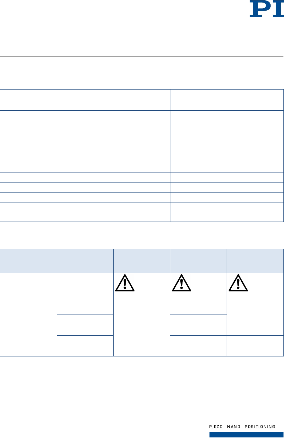
1.1 Symbols and Typographic Conventions
The following symbols and typographic conventions are used in this document:
CAUTION
Dangerous situation
If not avoided, the dangerous situation will result in minor injury.
Actions to take to avoid the situation.
NOTICE
Dangerous situation
If not avoided, the dangerous situation will result in damage to the equipment.
Actions to take to avoid the situation.
INFORMATION
− Information for easier handling, tricks, tips, etc.
User Manual
Page 4 / 33
2017-07-20
N216T0013, valid for N-216
Physik Instrumente (PI ) GmbH & Co. KG, Auf der Römerstraße 1, D-76228 Karlsruhe
Telefon +49 721 4846-0, Fax +49 721 4846-1019, Email info@pi.ws, www.pi.ws
Symbol / Label Meaning
1.
2.
Action consisting of several steps whose sequential order must be observed
Action consisting of one or several steps whose sequential order is irrelevant
List item
p. 5 Cross-reference to page 5
RS-232 Labeling of an operating element on the product (example: socket of the RS-232 interface)
Warning signs affixed to the product that refer to detailed information in this manual
1.2 Figures
For better understandability, the colors, proportions and degree of detail in illustrations can deviate from the
actual circumstances. Photographic illustrations may also differ and must not be seen as guaranteed properties.
1.3 Other Applicable Documents
The devices and software tools which are mentioned in this documentation are described in their own manuals.
Product Document
E-712 Digital Piezo Controller PZ195E User Manual
PIMikroMove SM148E Software Manual
For customer-specific models, additional Technical Notes may apply.
1.4 Intended Use
The N-216 is a laboratory device as defined by DIN EN 61010-1. It is intended to be used in interior spaces and
in an environment which is free of dirt, oil, and lubricants.
Based on its design and realization, the N-216 is intended for single-axis positioning, adjusting and shifting of
loads at various velocities.
The intended use of the N-216 is only possible when installed and in connection with a suitable controller (p. 9).
The controller is not included in the scope of delivery of the N-216.
In the ideal application case, the linear actuator is operated quasi-statically. In quasi-static operation, the load
is mainly kept at a particular position and only temporarily positioned (stepping mode).
User Manual
Page 5 / 33
2017-07-20
N216T0013, valid for N-216
Physik Instrumente (PI ) GmbH & Co. KG, Auf der Römerstraße 1, D-76228 Karlsruhe
Telefon +49 721 4846-0, Fax +49 721 4846-1019, Email info@pi.ws, www.pi.ws
2 Product Description
2.1 Features and Applications
• Travel range 20 mm
• Holding force up to 800 N
• Resolution to 0.03 nm Open-Loop, 5 nm Closed-Loop
• PiezoWalk® principle
• Self-locking, thus no holding currents and no heat generation at rest
• Non-magnetic function principle
• Can also be used in environments with:
− Clean room requirements
− Strong magnetic fields
− Strong UV radiation
− Vacuum (modified products up to 0.1 hPa, on request)
The N-216 NEXLINE® linear actuator is a compact drive for Nano positioning technology. The feed is generated
by coordinated shearing and clamping motions of strongly preloaded piezo elements that are coupled to a rod
(PiezoWalk® principle). In this way, NEXLINE® drives combine relatively long travel ranges with the nanometer
precision of piezo actuators.
Models N-216.1A1 and N-216.2A1 are equipped with a linear encoder for direct measurement of rod positions.
The resolution here is 5 nm over the entire travel range (closed-loop operation).
In highly dynamic analog operation, position resolutions up to 30 pm can be achieved (open-loop operation).
The linear actuator supports the following modes of operation for positioning a load:
Operating Mode Advantages
Full step mode Long travel ranges
High velocity
High dynamic forces
Nanostepping mode Long travel ranges
Low vibration
Uniformity of motion
Analog mode Travel ranges in the µm range
High dynamics
High resolution
Further details on the operating modes are found in the manual of the controller used.
User Manual
Page 6 / 33
2017-07-20
N216T0013, valid for N-216
Physik Instrumente (PI ) GmbH & Co. KG, Auf der Römerstraße 1, D-76228 Karlsruhe
Telefon +49 721 4846-0, Fax +49 721 4846-1019, Email info@pi.ws, www.pi.ws
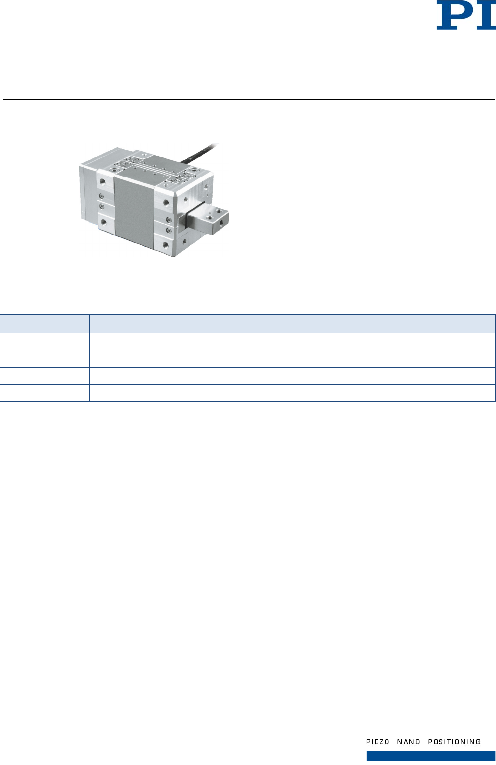
2.2 Model Overview
Figure 1: View of the N-216; applies for all models
Four standard versions of the N-216 NEXLINE® linear actuator are available. They differ regarding the presence
of an integrated position sensor (linear encoder) and in the drive force.
Model Properties
N-216.101 NEXLINE
®
Piezo Stepping High-Load Actuator, 20 mm, 300 N, Open-Loop
N-216.1A1
NEXLINE
®
Piezo Stepping High-Load Actuator, 20 mm, 300 N, Linear Encoder, 5 nm Resolution
N-216.201 NEXLINE
®
Piezo Stepping High-Load Actuator, 20 mm, 600 N, Open-Loop
N-216.2A1 NEXLINE
®
Piezo Stepping High-Load Actuator, 20 mm, 600 N, Linear Encoder, 5 nm Resolution
For further technical data, see the specifications (p. 25).
PI also produces custom designs upon request. Custom designs can differ from the described standard
products in respect to dimensions, characteristics or other technical data.
If necessary, contact our customer service department (p. 24) directly.
User Manual
Page 7 / 33
2017-07-20
N216T0013, valid for N-216
Physik Instrumente (PI ) GmbH & Co. KG, Auf der Römerstraße 1, D-76228 Karlsruhe
Telefon +49 721 4846-0, Fax +49 721 4846-1019, Email info@pi.ws, www.pi.ws
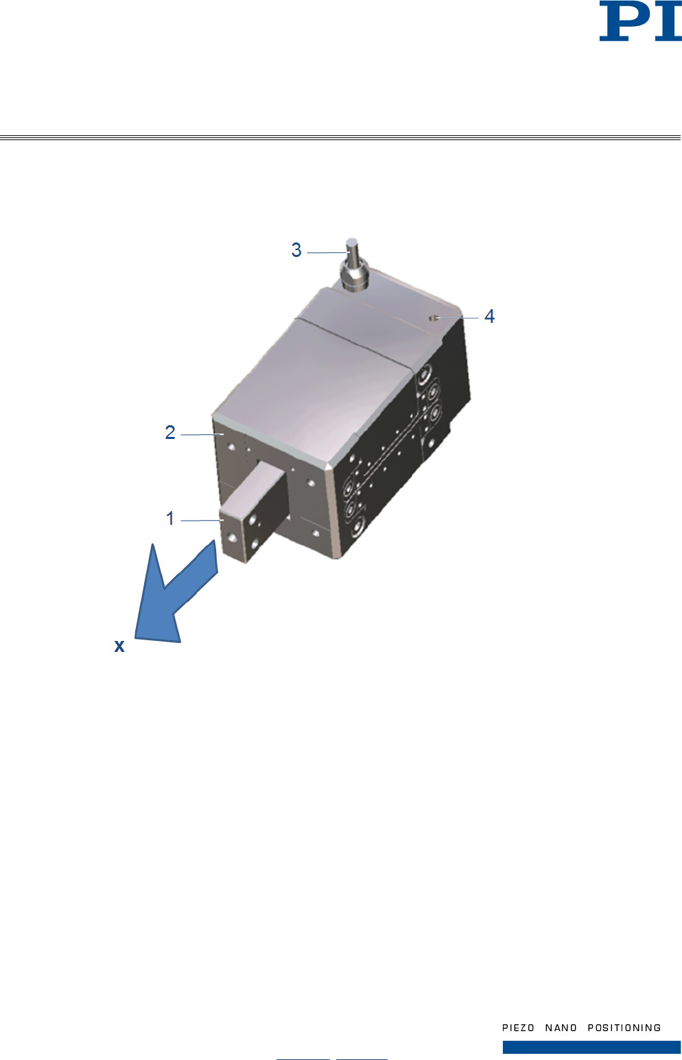
2.3 Product View
2.3.1 Product Details
Figure 2: Position of important elements
1 Rod
2 Actuator case
3 Connection cable
4 Protective earth connection
x Positive direction of rod motion
User Manual
Page 8 / 33
2017-07-20
N216T0013, valid for N-216
Physik Instrumente (PI ) GmbH & Co. KG, Auf der Römerstraße 1, D-76228 Karlsruhe
Telefon +49 721 4846-0, Fax +49 721 4846-1019, Email info@pi.ws, www.pi.ws
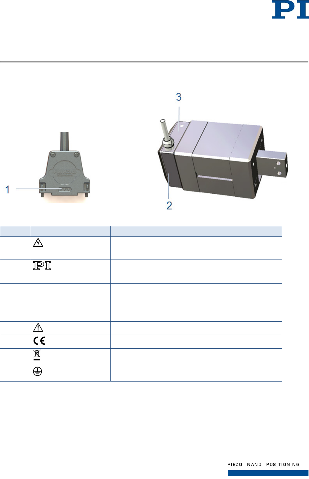
2.3.2 Product Labeling
Position Label Description
1 Warning symbol “High Voltage”
2 N-216.1A1 Product name
2 Manufacturer's logo
2 WWW.PI.WS Manufacturer's address (website)
2 Country of origin: Germany Country of origin
2 114007694 Serial number (example), individual for each N-422
Meaning of the places (counting from left): 1 = internal information,
2 and 3 = manufacturing year, 4 to 9 = consecutive numbers
2 Warning sign "Observe manual!"
2 CE conformity mark
2 Old equipment disposal (p. 33)
3 Protective earth symbol (indicating the location of the protective
earth connection)
User Manual
Page 9 / 33
2017-07-20
N216T0013, valid for N-216
Physik Instrumente (PI ) GmbH & Co. KG, Auf der Römerstraße 1, D-76228 Karlsruhe
Telefon +49 721 4846-0, Fax +49 721 4846-1019, Email info@pi.ws, www.pi.ws
2.4 Scope of Delivery
The N-216 is delivered with the following components.
Order Number Component
N-216.xx1 Linear actuator according to order
N216E0006 Mounting flange A
N216E0008 Mounting flange B
000036450 M4 screw set for protective earth connection
2175 Mounting screws DIN EN ISO 4762-M4x8-A2 (4 pcs.)
2176 Mounting screws DIN 7984-M5x10-A4-70 (4 pcs.)
N216T0013 Technical Note (this document) in printed form
Packaging materials
2.5 Suitable Controllers
Controller Description
E-712.1AM Modular system with piezo amplifier module for NEXLINE
®
drives
2.6 Only N-216.1A1 / N-216.2A1: Technical Features for Closed-Loop Operation
2.6.1 Linear Encoder
The linear actuator is equipped with an optical linear encoder. For the encoder resolution, refer to the table in
the "Specifications" (p. 25) section.
Optical linear encoders measure the actual position directly (direct metrology). Therefore, errors occurring in the
drivetrain, such as nonlinearity, backlash or elastic deformation, cannot influence the measurement of the
position.
2.6.2 Reference Point Switch
The linear actuator is equipped with a direction-sensing reference point switch that is located approximately in
the middle of the travel range. This sensor transmits a TTL signal that indicates whether the linear actuator is on
the positive or negative side of the reference point switch.
The commands that use the reference signal are described in the user manual of the controller and/or in the
corresponding software manuals.
3 Unpacking
1. Unpack the N-216 with care.
2. Compare the contents against the items covered by the contract and against the packing list.
3. Inspect the contents for signs of damage. If parts are missing or you notice signs of damage, contact PI
immediately.
4. Keep all packaging materials in case the product needs to be returned.

User Manual
Page 10 / 33
2017-07-20
N216T0013, valid for N-216
Physik Instrumente (PI ) GmbH & Co. KG, Auf der Römerstraße 1, D-76228 Karlsruhe
Telefon +49 721 4846-0, Fax +49 721 4846-1019, Email info@pi.ws, www.pi.ws
4 Installation
4.1 Mounting the N-216 onto a Surface
INFORMATION
In order to achieve an optimum repeatability, the linear actuator must be mounted
without backlash.
During mounting, ensure that the connection between the linear actuator and the
installation environment is faultless.
User Manual
Page 11 / 33
2017-07-20
N216T0013, valid for N-216
Physik Instrumente (PI ) GmbH & Co. KG, Auf der Römerstraße 1, D-76228 Karlsruhe
Telefon +49 721 4846-0, Fax +49 721 4846-1019, Email info@pi.ws, www.pi.ws
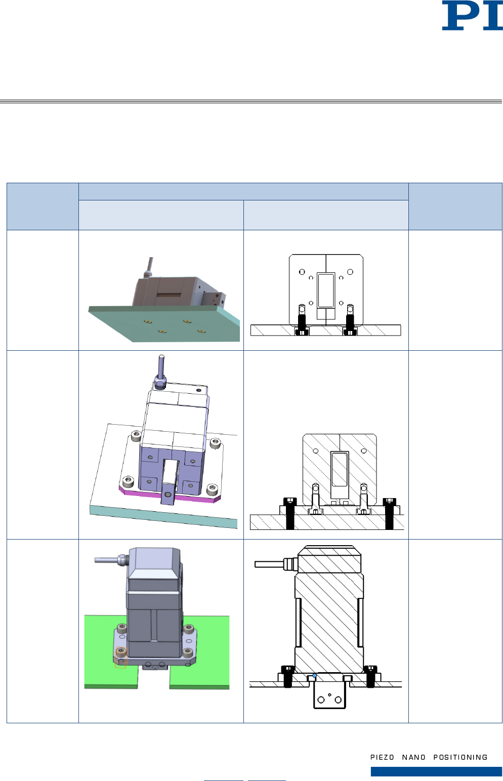
4.1.1 Options
Depending on the environment of your application, the following options may be applicable for mounting the
actuator on a surface:
Option Illustration (Example) Preparation of the
actuator for
surface mounting
Spatial view Sectional view
(Note the highlighted screws)
Direct
mounting
(Illustrated
example:
“bottom”
side*; for
details see
paragraph
4.1.4)
None
Mounting
with
mounting
flange A
applied
Mounting the
mounting flange A
on the actuator
(see paragraph
4.1.2)
Mounting
with
mounting
flange B
applied
Mounting the
mounting flange B
on the actuator
(see paragraph
4.1.3)
* Using the threaded holes in the “rod side” of the actuator case is also applicable, see paragraph 4.1.4.
User Manual
Page 12 / 33
2017-07-20
N216T0013, valid for N-216
Physik Instrumente (PI ) GmbH & Co. KG, Auf der Römerstraße 1, D-76228 Karlsruhe
Telefon +49 721 4846-0, Fax +49 721 4846-1019, Email info@pi.ws, www.pi.ws
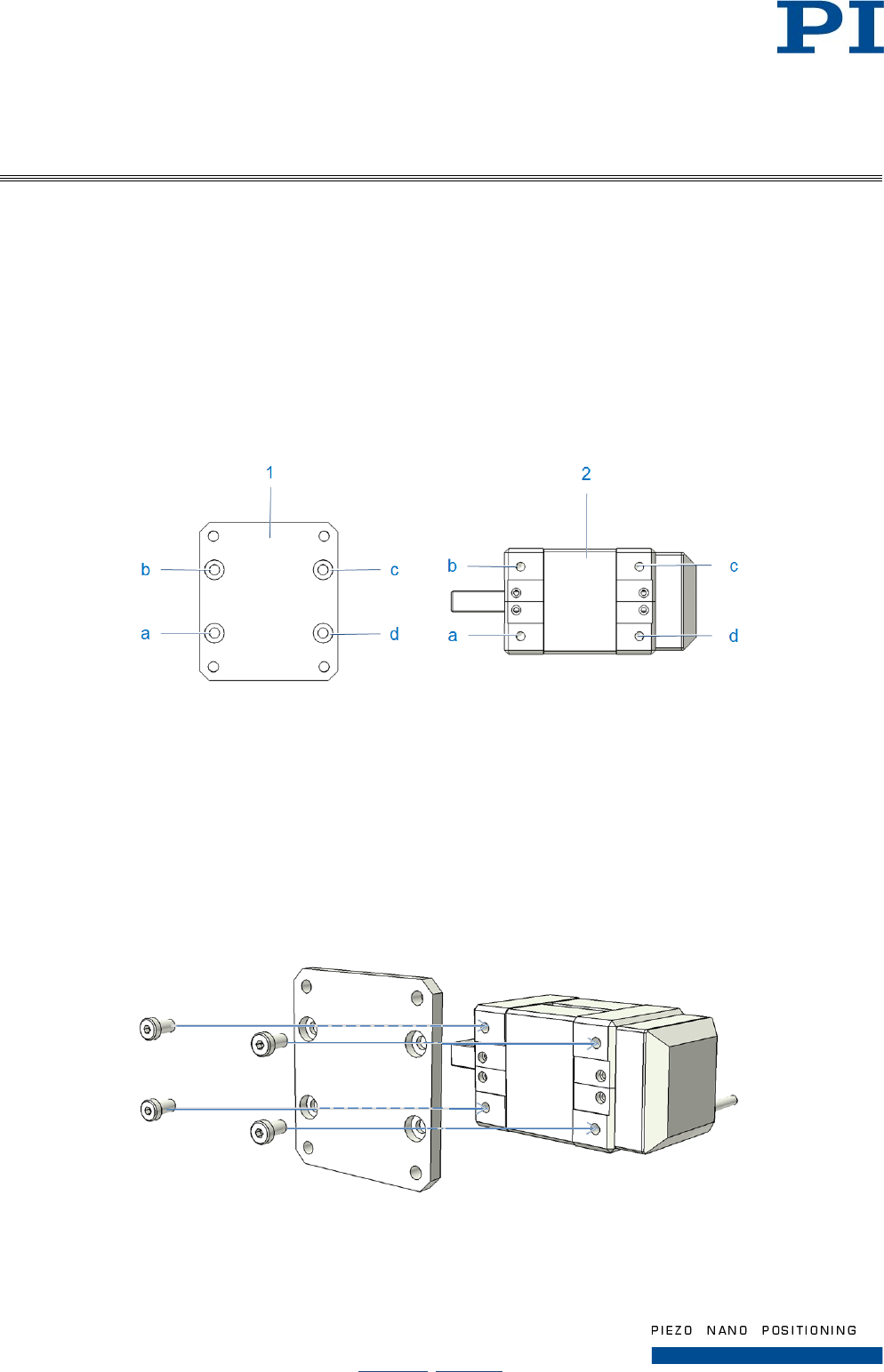
4.1.2 Mounting the Mounting Flange A onto the Actuator
Tools and accessories
• Mounting flange A (N216E0006)
• Four M5x10 cylinder head screws (DIN 7984), included in the delivery
• Hexagonal key AF 4 (or compliant screwdriver)
Requirements
• The linear actuator is not connected to the controller.
Figure 3: Used mounting holes for flange A mounting
1 Mounting flange A with
a - d) mounting holes with counter bores
2 Actuator with
a - d) threaded mounting holes
Holes that overlap during attachment are marked with the same letters.
1. Position the mounting holes in the mounting plate over the corresponding holes in the actuator (see
figure above). Note that the counter bores must be visible (face-up).
2. Completely screw in the cylinder head screws at all mounting holes (see figure below).
Figure 4: Mounting the mounting flange A, exploded view
3. Check that the linear actuator fits onto the surface without backlash.
User Manual
Page 13 / 33
2017-07-20
N216T0013, valid for N-216
Physik Instrumente (PI ) GmbH & Co. KG, Auf der Römerstraße 1, D-76228 Karlsruhe
Telefon +49 721 4846-0, Fax +49 721 4846-1019, Email info@pi.ws, www.pi.ws
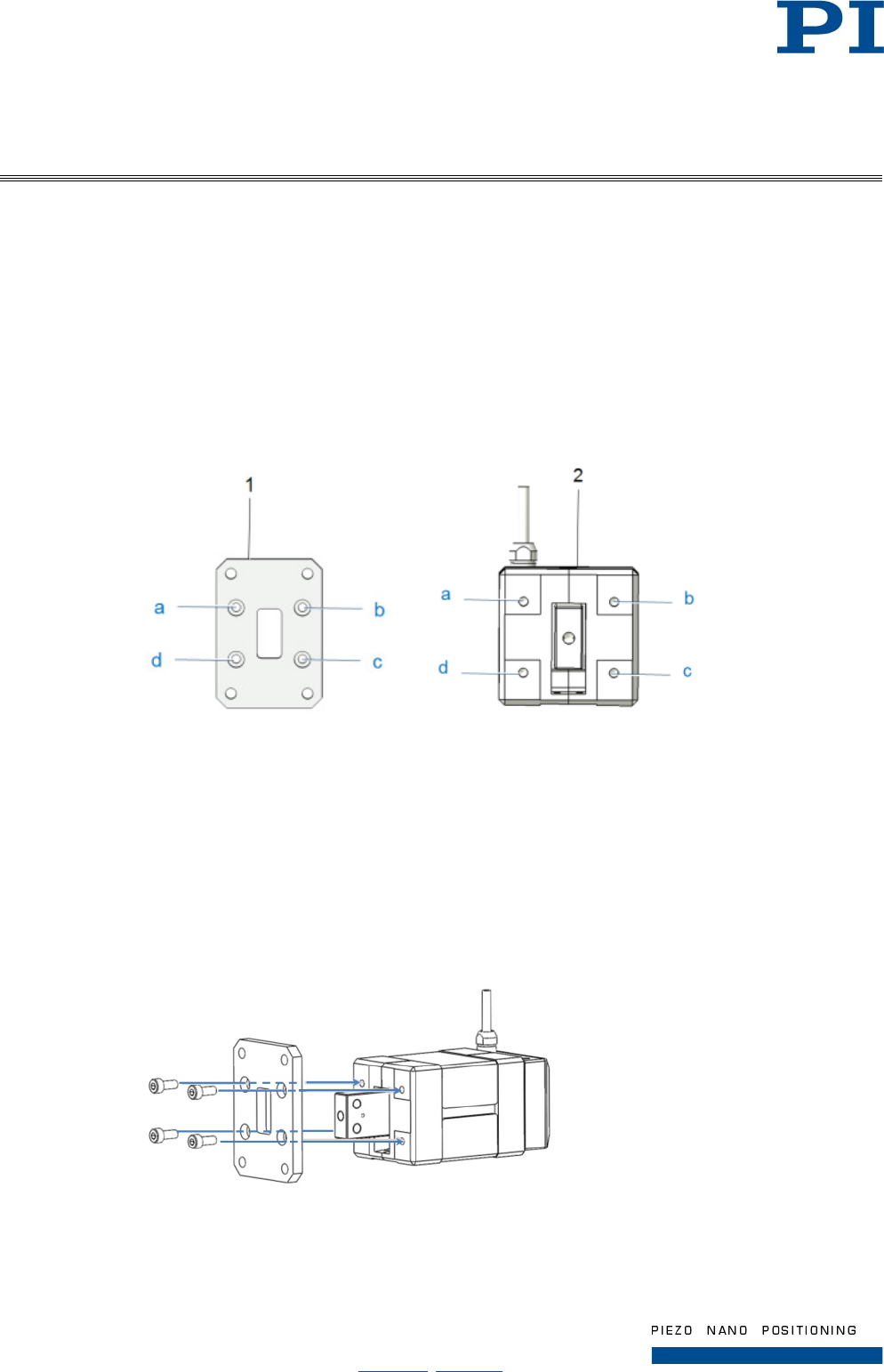
4.1.3 Mounting the Mounting Flange B onto the Actuator
Tools and accessories
• Mounting flange B (N216E0008)
• Four M4x8 (ISO 4762) cylinder head screws, included in the delivery
• Hexagonal key AF 3 (or compliant screwdriver)
Requirements
• The linear actuator is not connected to the controller.
Figure 5: Used mounting holes for flange B mounting
1 Mounting flange B with
a - d) mounting holes with counter bores
2 Actuator with
a - d) threaded mounting holes
Holes that overlap during attachment are marked with the same letters.
1. Position the mounting holes in the mounting plate over the corresponding holes in the actuator (see
figure above). Note that the counter bores must be visible (face-up).
2. Completely screw in the cylinder head screws at all mounting holes (see figure below).
Figure 6: Mounting the mounting flange B, exploded view
3. Check that the linear actuator fits onto the surface without backlash.
User Manual
Page 14 / 33
2017-07-20
N216T0013, valid for N-216
Physik Instrumente (PI ) GmbH & Co. KG, Auf der Römerstraße 1, D-76228 Karlsruhe
Telefon +49 721 4846-0, Fax +49 721 4846-1019, Email info@pi.ws, www.pi.ws
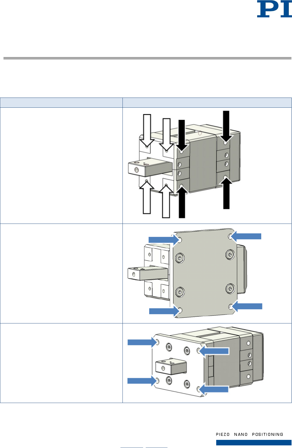
4.1.4 Mounting the N-216 onto a Surface
Depending on the selected mounting option, the following holes are used for mounting the N-216 onto a surface
(refer to the arrows in the illustrations):
Mounting option Positions of the used mounting holes
Direct mounting
(Use positions indicated either by black or white
arrows)
Mounting with mounting flange A applied
Mounting with mounting flange B applied
User Manual
Page 15 / 33
2017-07-20
N216T0013, valid for N-216
Physik Instrumente (PI ) GmbH & Co. KG, Auf der Römerstraße 1, D-76228 Karlsruhe
Telefon +49 721 4846-0, Fax +49 721 4846-1019, Email info@pi.ws, www.pi.ws
Tools and accessories
INFORMATION
Depending on the thickness of the surface, the screws included in the delivery may
suit for direct mounting.
• Four screws M5 (Exception: M4 screws for direct mounting on the rod side of the actuator case);
length adapted on the depth of the threaded holes in the surface
• Suitable screwdriver or hexagonal key (e.g. AF 4 for mounting M5 cylinder head screws)
Requirements
• You have provided a surface with four threaded holes with distances corresponding to the dedicated
holes in the used mounting flange or of the N-216, depending on the selected mounting option (see
chapter 9.4 Dimensions).
• The linear actuator is not connected to the controller.
Mounting the N-216 on a surface
1. Depending on the mounting option, position the mounting holes either in the actuator or in the mounting
plate of the linear actuator (see figure) over the corresponding holes in the surface.
2. Completely screw in the cylinder head screws at all used mounting holes.
3. Check that the linear actuator fits onto the surface without backlash.
4.2 Connecting the N-216 to the Protective Earth Conductor
INFORMATION
Observe the applicable standards for mounting the protective earth conductor.
INFORMATION
The hole for the protective earth connection is marked on the product (p. 8).
Tools and accessories
• Suitable protective earth conductor: with cross-section ≥ 0.75 mm2, resistance <0.1 Ω at 25 A,
insulation green/yellow
• M4 screw set (included in the scope of delivery of the linear actuator)
• Philips-head screwdriver (PH 2)
User Manual
Page 16 / 33
2017-07-20
N216T0013, valid for N-216
Physik Instrumente (PI ) GmbH & Co. KG, Auf der Römerstraße 1, D-76228 Karlsruhe
Telefon +49 721 4846-0, Fax +49 721 4846-1019, Email info@pi.ws, www.pi.ws
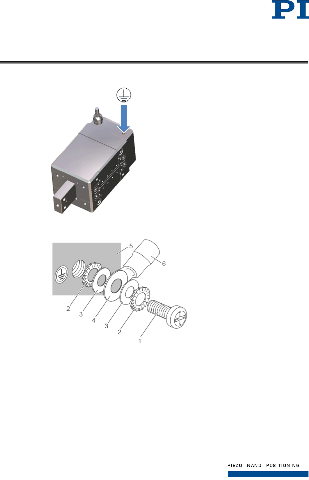
Connecting the N-216 to the protective earth conductor
Figure 7: Position of the protective earth connector
Figure 8: Mounting of protective earth connection (schematic)
1. M4 screw
2. Toothed washer
3. Flat washer
4. Cable lug
5. Linear actuator case with protective earth connection (M4 threaded hole) and protective earth conductor
symbol
6. Protective earth conductor
1. If necessary, fasten a suitable cable lug to the protective earth conductor.
2. Remove the screw, the toothed washers and flat washers from the package of the screw set.
User Manual
Page 17 / 33
2017-07-20
N216T0013, valid for N-216
Physik Instrumente (PI ) GmbH & Co. KG, Auf der Römerstraße 1, D-76228 Karlsruhe
Telefon +49 721 4846-0, Fax +49 721 4846-1019, Email info@pi.ws, www.pi.ws
3. As shown in the above figure: fasten one flat washer and one toothed washer each above and below
the protective earth conductor or its cable lug with the screw on the protective earth connection of the
linear actuator (position of the protective earth connection on the linear actuator: see figure above).
4. Tighten the screw with a torque of 1.2 Nm to 1.5 Nm.
5. Make sure that the protective earth conductor of the linear actuator is properly connected with the
existing protective earth system within your application at all times.
4.3 Affixing Load to the N-216
NOTICE
Impermissibly high load on the linear actuator
Impermissibly high loads inhibit the motion of the rod and can damage or destroy the
linear actuator.
With respect to mass and fastening type of the load, observe the maximum
permissible active and passive forces and the resulting torques that are allowed to
act on the rod according to the specification (p. 25).
INFORMATION
In order to achieve an optimum repeatability, the load must be mounted without
backlash.
During mounting, ensure that the connection between the linear actuator and the
load is faultless.
Requirements
• You have properly fastened the linear actuator according to the corresponding instructions (p. 10).
• The linear actuator is not connected to the controller.
Tools and accessories
• M5 fastening screw with suitable length (depth of the threaded hole: 8 mm; further dimensions see
p. 29).
• If necessary: M5 spring washer(s) or flat washer(s)
• Open-end wrench, AF 10 and / or AF 22
• Suitable screwdriver, hexagonal key or open-end wrench for the fastening screw(s)
User Manual
Page 18 / 33
2017-07-20
N216T0013, valid for N-216
Physik Instrumente (PI ) GmbH & Co. KG, Auf der Römerstraße 1, D-76228 Karlsruhe
Telefon +49 721 4846-0, Fax +49 721 4846-1019, Email info@pi.ws, www.pi.ws
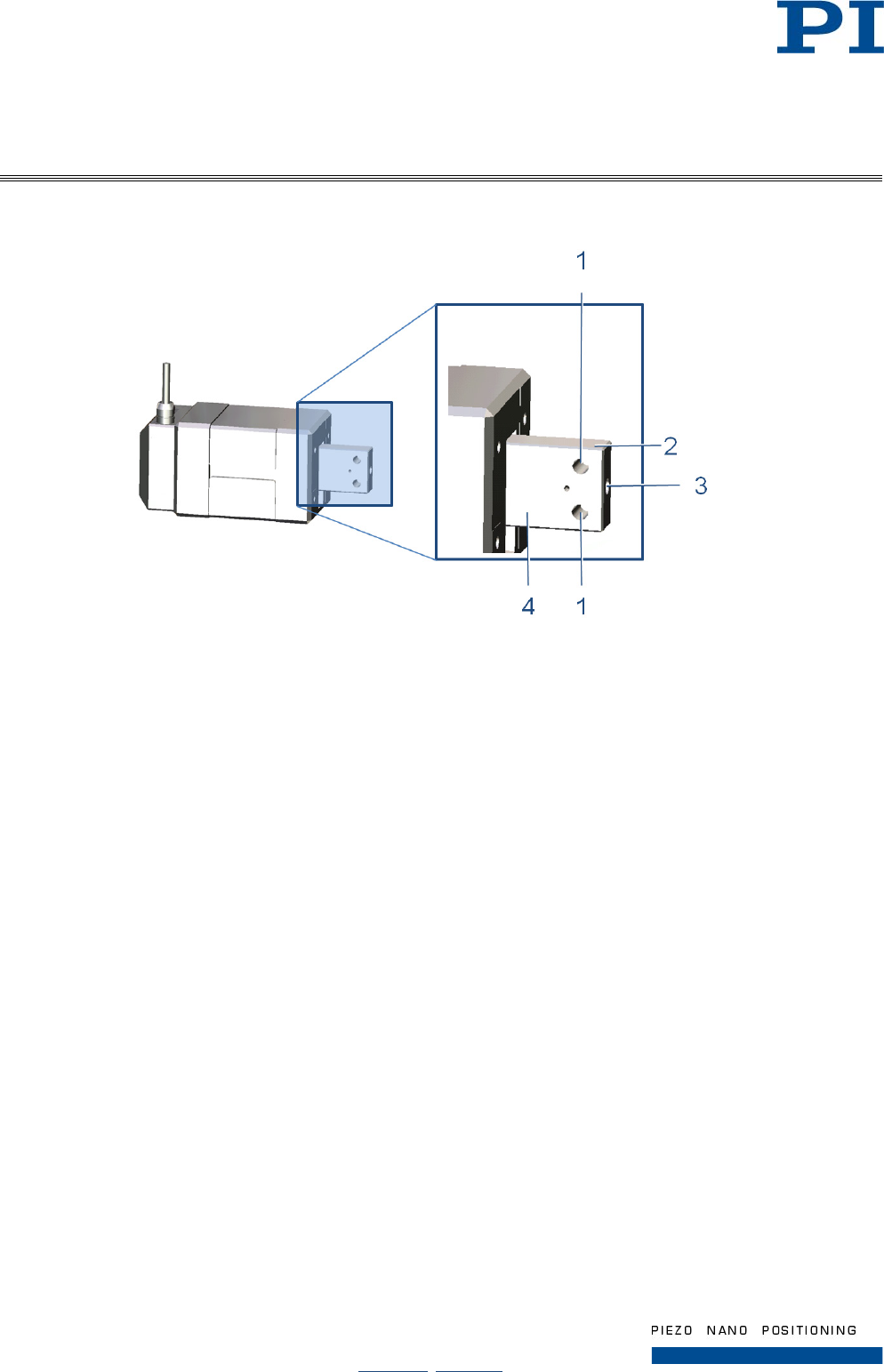
Affixing load to the N-216
Figure 9: Relevant components of the rod for affixing the load
1 Tapped through hole M5 for affixing the load
2 Narrow plane of the rod *
3 Tapped blind hole M5 (depth 8 mm) for affixing the load
4 Broad plane of the rod *
* A corresponding further (parallel) plane is present, but not visible in this view
1. Fix the rod by applying the open-end wrench to the planes of the rod.
Options:
• Embrace the narrow planes of the rod with the open-end wrench AF 22
• Embrace the broad planes of the rod with the open-end wrench AF 10.
2. Affix the load on the hole(s) in the rod of the linear actuator with the fastening screw(s) and, if
necessary, attached spacers, safety washers or spring washers: Screw in the screw(s) until you feel a
resistance and tighten the screw(s) with a torque of 3.5 Nm to 5 Nm.
3. Check whether a backlash-free connection is ensured at all times.
User Manual
Page 19 / 33
2017-07-20
N216T0013, valid for N-216
Physik Instrumente (PI ) GmbH & Co. KG, Auf der Römerstraße 1, D-76228 Karlsruhe
Telefon +49 721 4846-0, Fax +49 721 4846-1019, Email info@pi.ws, www.pi.ws
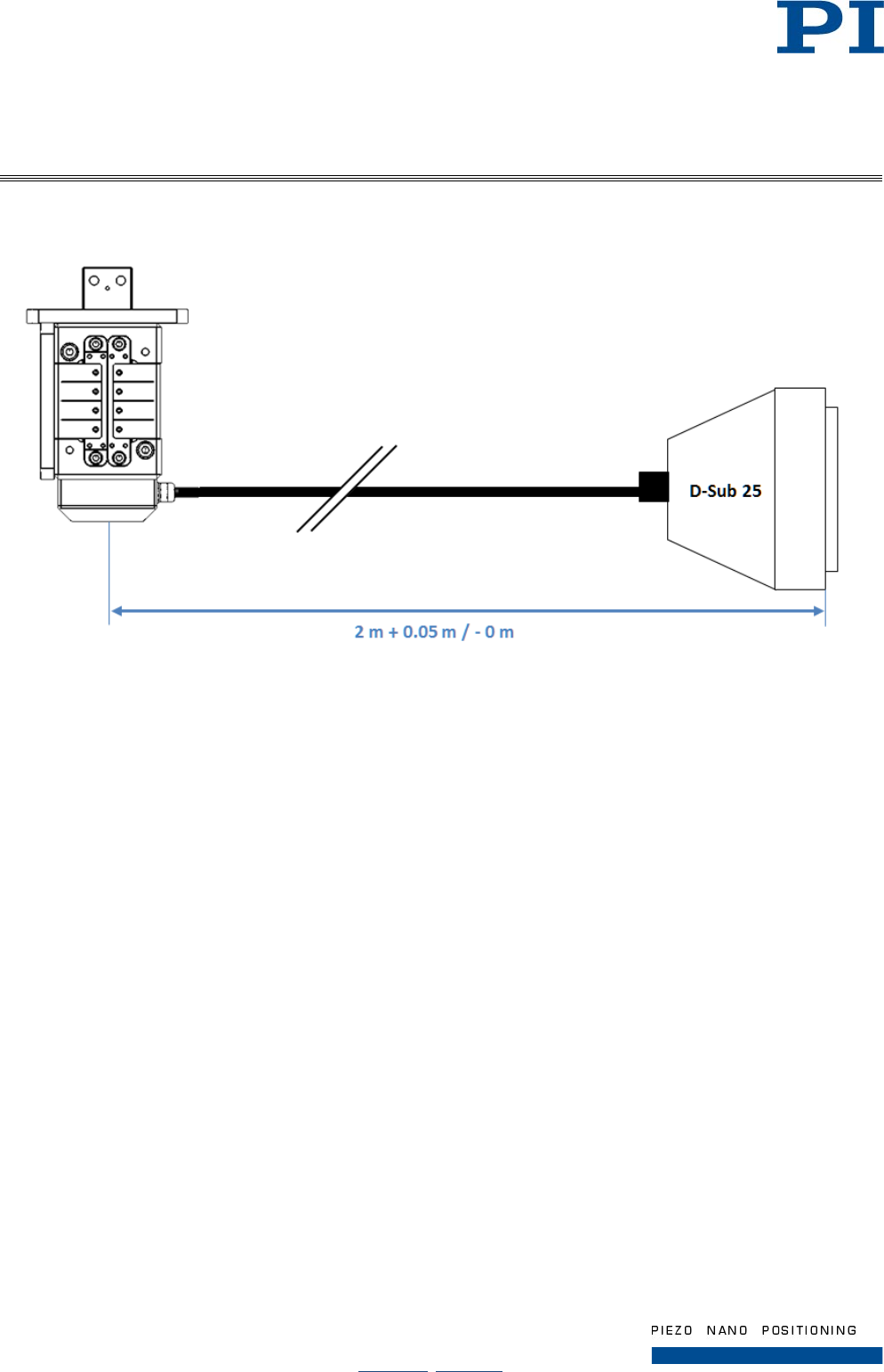
4.4 Connecting the N-216 to the Controller
Figure 10: Cable diagram
Requirements
You have properly mounted the linear actuator (p. 10) and connected the protective earth conductor (p. 15).
You have installed a suitable controller (p. 9).
You have read and understood the user manual of the controller.
Connecting the N-216 to the controller
1. Connect the connector of the linear actuator with the corresponding socket of the controller (see user
manual of the controller).
2. Secure the connection with the integrated screws against being accidently pulled out.
3. Eliminate or label resulting danger areas in accordance with the valid regulations and
recommendations.
User Manual
Page 20 / 33
2017-07-20
N216T0013, valid for N-216
Physik Instrumente (PI ) GmbH & Co. KG, Auf der Römerstraße 1, D-76228 Karlsruhe
Telefon +49 721 4846-0, Fax +49 721 4846-1019, Email info@pi.ws, www.pi.ws
5 Start-Up and Operation
5.1 General Notes on Start-Up and Operation
CAUTION
Risk of electric shock if the protective earth conductor is not connected!
If a protective earth conductor is not or not properly connected, dangerous touch
voltages can occur on the N-216 in the case of malfunction or failure of the system. If
touch voltages exist, touching the N-216 can result in minor injuries due to electric
shock.
Connect the N-216 to a protective earth conductor before start-up (p. 15).
Do not remove the protective earth conductor during operation.
If the protective earth conductor has to be removed temporarily (e. g. in the case
of modifications), reconnect the N-216 to the protective earth conductor before
starting it up again.
CAUTION
Dangerous voltage and residual charge on piezo actuators!
The N-216 is driven by piezo actuators. Temperature changes and compressive
stresses can induce charges in piezo actuators. After being disconnected from the
electronics, piezo actuators can also stay charged for several hours. Touching or
short-circuiting the contacts in the connector of the N-216 can lead to minor injuries.
In addition, the piezo actuators can be destroyed by an abrupt contraction.
Do not open the N-216.
Do not touch the contacts in the connector of the linear actuator.
Secure the connector of the linear actuator with screws against being pulled out
of the controller.
If you want to pull out the connector of the linear actuator:
Do not pull out the connector from the controller during operation.
Discharge the linear actuator before pulling out the connector (p. 23).
If possible: Switch off the controller and wait at least 10 seconds before pulling
out the connector.
User Manual
Page 21 / 33
2017-07-20
N216T0013, valid for N-216
Physik Instrumente (PI ) GmbH & Co. KG, Auf der Römerstraße 1, D-76228 Karlsruhe
Telefon +49 721 4846-0, Fax +49 721 4846-1019, Email info@pi.ws, www.pi.ws
CAUTION
Burning from hot surface!
The surface of the actuator can become hot during operation. Touching the actuator
can cause slight injuries from burning.
Cool the actuator e.g. with protective air so that the temperature of its surface
does not exceed 65 °C.
If sufficient cooling is not possible: Make sure that the hot actuator cannot be
touched.
When sufficient cooling and protection against contact are not possible: Mark the
danger zone according to the legal regulations.
The actuator must be operated only after completed installation.
NOTICE
Destruction of the drive at the end position due to continuous high voltage!
High voltages that are applied to the piezo actuators can damage the NexLine®
drive.
If it is necessary to hold a constant position for one hour or longer:
After reaching the target position, set the voltage at the drive to 0 V either
manually or with the "RNP" command.
Afterwards, make sure that the desired operating mode (open loop / closed
loop) is maintained.
NOTICE
Heating up of the N-216 during operation!
The heat produced during constant or dynamic operation of the N-216 can affect
your application.
Install the N-216 so that your application is not affected by the dissipating heat.
NOTICE
Uncontrolled oscillation!
Your application and the N-216 can be damaged by uncontrolled oscillations.
Uncontrolled oscillations can be identified by the fact that the linear actuator
approaches the target position too slowly or too fast or does not keep it stable (servo
jitter).
If uncontrolled oscillations occur during the operation of the N-216:
Immediately switch off the servo-control system of the affected axis.
Check the settings of the servo control parameters.
User Manual
Page 22 / 33
2017-07-20
N216T0013, valid for N-216
Physik Instrumente (PI ) GmbH & Co. KG, Auf der Römerstraße 1, D-76228 Karlsruhe
Telefon +49 721 4846-0, Fax +49 721 4846-1019, Email info@pi.ws, www.pi.ws
NOTICE
Increased friction due to lateral forces on the rod.
Lateral forces that act on the rod of the linear actuator increase the friction between
the rod and other drive components. Increased friction inhibits the motion of the rod
and increases the wear of the drive components.
Avoid lateral forces on the rod of the linear actuator.
INFORMATION
For sending commands to the linear actuator, the outward motion of the rod is
defined as positive direction of motion.
INFORMATION
In the ideal application case, the linear actuator is operated quasi-statically. In quasi-
static operation, the load is mainly kept at a particular position and only temporarily
positioned (stepping mode).
For N-216.1A1 / N-216.2A1, the following also applies:
INFORMATION
The repeatability of the positioning is only ensured when the reference point switch is
always approached from the same side. Recommended controllers from PI fulfill this
requirement with their automatic direction detection for reference moves to the
reference switch.
5.2 Operating the N-216
Requirements
• You have read and understood the user manual of the controller.
• You have read and understood the user manual of the PC software.
• You have properly mounted the linear actuator (p. 10), connected the protective earth conductor
(p. 15) and the load (p. 17).
• The controller and the required PC software have been installed. All connections with the controller
have been established (see user manual of the controller).
Operating the N-216
Follow the instructions in the manual of the used controller for start-up and operation of the N-216.
User Manual
Page 23 / 33
2017-07-20
N216T0013, valid for N-216
Physik Instrumente (PI ) GmbH & Co. KG, Auf der Römerstraße 1, D-76228 Karlsruhe
Telefon +49 721 4846-0, Fax +49 721 4846-1019, Email info@pi.ws, www.pi.ws
5.3 Discharging the N-216
The N-216 must be discharged in the following cases:
• When the N-216 is not used but the controller remains switched on to ensure temperature stability
• Before demounting (e.g. before cleaning and transport of the N-216 and for modifications of the
application)
• Before pulling out the connector of the N-216
Discharging the N-216 that is connected to the controller
If you are working in closed-loop operation:
1. Switch off the servo mode on the controller.
2. Set the piezo voltage to 0 V on the controller.
If you are working in open-loop operation:
Set the piezo voltage to 0 V on the controller.
Discharging the N-216 that is not connected to the controller
Connect the linear actuator to the switched-off controller from PI.
6 Maintenance
6.1 General Notes on Maintenance
NOTICE
Damage due to improper maintenance!
The linear actuator can become misaligned as a result of improper maintenance. The
specifications can change as a result (p. 25).
Do not loosen screws that are part of the actuator case.
6.2 Cleaning the N-216
Requirements
• You have disconnected the linear actuator from the controller.
Cleaning the linear actuator
When necessary, clean the linear actuator surface with a towel lightly dampened with a mild cleanser or
disinfectant.
Do not apply ultrasonic cleaning.

User Manual
Page 24 / 33
2017-07-20
N216T0013, valid for N-216
Physik Instrumente (PI ) GmbH & Co. KG, Auf der Römerstraße 1, D-76228 Karlsruhe
Telefon +49 721 4846-0, Fax +49 721 4846-1019, Email info@pi.ws, www.pi.ws
7 Troubleshooting
Problem Possible Causes Solution
Target position is approached too
slowly or with overshoot
Servo-control parameters are
not optimally set
Large changes in the load
1. Switch off the servo-control system
immediately.
2. Check the settings of the servo-control
parameters.
3. If necessary, correct the settings of the
servo-control parameters.
Target position is not kept stable
Uncontrolled oscillations of the
N-216
Increased wear Excessive lateral forces on the rod Avoid lateral forces on the rod of the
N-216.
Reduced accuracy
No or limited motion
Excessive load
Excessive counterforces in the
direction of motion
Reduce the load (see "Mechanical Load
Capacity" (p. 27)).
In the case of vertical mounting:
Ensure gravity compensation so that the
maximum load (p. 27) is not exceeded.
If the problem that occurred with your system is not listed in the table above or cannot be solved as described,
contact our customer service department (p. 24).
8 Customer Service
For inquiries and orders, contact your PI sales engineer or send us an e-mail (mailto:info@pi.ws).
If you have questions concerning your system, have the following information ready:
• Product codes and serial numbers of all products in the system
• Firmware version of the controller (if present)
• Version of the driver or the software (if present)
• Operating system on the PC (if present)
User Manual
Page 25 / 33
2017-07-20
N216T0013, valid for N-216
Physik Instrumente (PI ) GmbH & Co. KG, Auf der Römerstraße 1, D-76228 Karlsruhe
Telefon +49 721 4846-0, Fax +49 721 4846-1019, Email info@pi.ws, www.pi.ws
9 Technical Data
9.1 Specifications
9.1.1 Data Table
Model
N-216.101 / N-216.1A1
N-216.201 / N-216.2A1
Tolerance
Active axes
X
X
Motion and positioning
Displacement
20 mm
20 mm
Step size (in step mode)
10 nm to 10 µm
10 nm to 10 µm
Travel range in analog mode
±3 µm
±3 µm
Integrated sensor
N-216.101: none,
N-216.1A1: linear encoder
N-216.201: none,
N-216.2A1: linear encoder
Open-loop resolution
0.03 nm
0.03 nm
typ.
Closed-loop resolution
– / 5 nm (N-216.1A1)
– / 5 nm (N-216.2A1)
Max. velocity,
(10% duty cycle, full step mode)
1.0 mm/s
1.0 mm/s
Max. velocity,
(100% duty cycle, full step mode)
0.6 mm/s
0.6 mm/s
Max. velocity,
(100% duty cycle, nanostepping mode)
0.4 mm/s
0.4 mm/s
Mechanical properties
Drive force (active)*
300 N
600 N
max.
Holding force (passive)
400 N
800 N
min.
Drive properties
Motor type
NEXLINE®
NEXLINE®
Operating voltage
-250 V to +250 V,
0 to 100 Hz (typical)
-250 V to +250 V,
0 to 100 Hz (typical)
Miscellaneous
Operating temperature range
-40 to 80 °C
-40 to 80 °C
Material
Aluminum, stainless steel
Aluminum, stainless steel
Mass
1150 g
1250 g
Cable length
2.0 m
2.0 m
Connector
D-Sub 25 (m)
D-Sub 25 (m)
Recommended controller
E-712.1AM
E-712.1AM
* Data refer to full step mode operation.
User Manual
Page 26 / 33
2017-07-20
N216T0013, valid for N-216
Physik Instrumente (PI ) GmbH & Co. KG, Auf der Römerstraße 1, D-76228 Karlsruhe
Telefon +49 721 4846-0, Fax +49 721 4846-1019, Email info@pi.ws, www.pi.ws
9.1.2 Ambient Conditions and Classifications
The following ambient conditions and classifications must be observed for the N-216:
Area of application For indoor use only
Maximum altitude 2000 m
Air pressure 1100 hPa to 0.1 hPa
Relative humidity Max. 80% for temperatures to 31 °C, non-
condensing
Decreasing linearly to 50% at 40 °C, non-
condensing
Operating temperature -40 °C to 80 °C
Storage temperature -40 °C to 80 °C
Transport temperature -40 °C to 80 °C
Overvoltage category (acc. to EN 60664-1:2007 / VDE 0110-1) II
Protection class (acc. to EN 61140 / VDE 0140-1) I
Degree of pollution (acc. to EN 60664-1:2007 / VDE 0110-1) 1
Degree of protection (acc. to IEC 60529) IP 20
9.2 Maximum Ratings
The linear actuator is designed for the following operating data:
Model Mode of Operation Maximum Operating
Voltage
Maximum Operating
Frequency or
Velocity (Unloaded)
Maximum Power
Consumption 1)
N-216.101 / N-216.
1A1
Analog +250 V; -250 V 1500 Hz 3.5 W
2)
Full step 600 µm/s 6.6 W
Nanostepping 400 µm/s
N-216.201 / N-216.
2A1
Analog 2000 Hz 7 W
2)
Full step 600 µm/s 13.2 W
Nanostepping 400 µm/s
1) for constant dynamic operation (not recommended!)
2) at full amplitude and max. frequency of 100 Hz
User Manual
Page 27 / 33
2017-07-20
N216T0013, valid for N-216
Physik Instrumente (PI ) GmbH & Co. KG, Auf der Römerstraße 1, D-76228 Karlsruhe
Telefon +49 721 4846-0, Fax +49 721 4846-1019, Email info@pi.ws, www.pi.ws
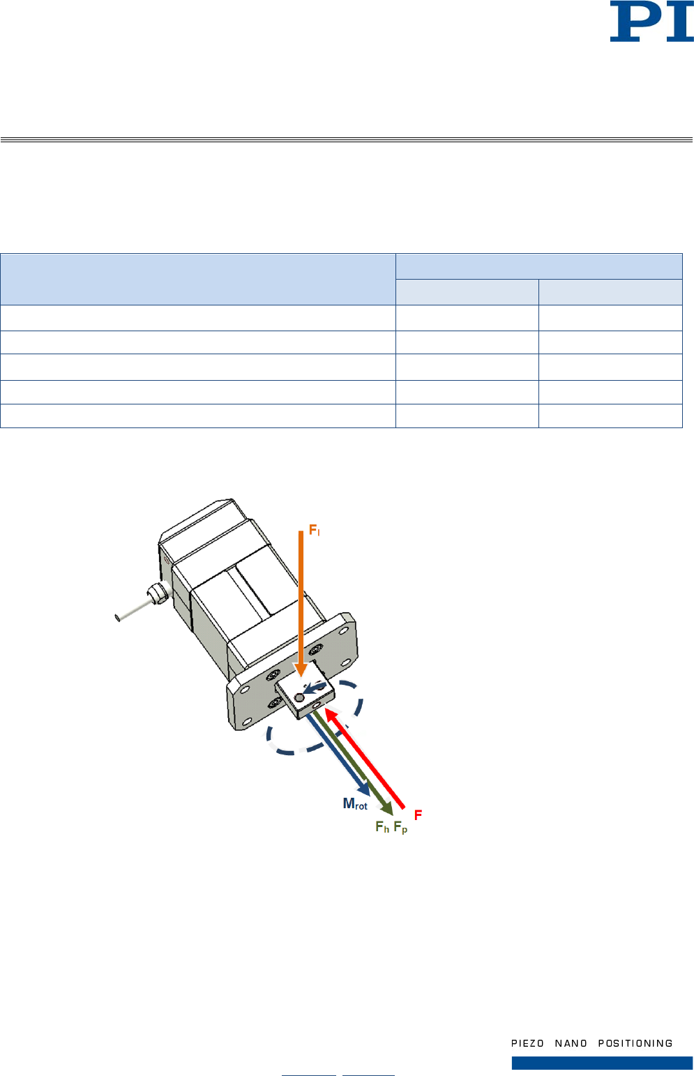
9.3 Mechanical Load Capacity
Maximum values for torque and forces
Negative values in the table correspond to a reversal of the effective direction according to the following figure.
Parameter Permissible Values
N-216.101 / N-216.1A1 N-216.201 / N-216.2A1
Passive force (holding force, linear actuator currentless) Fh - 400 N to 400 N - 800 N to 800 N
Active force (drive force) Fp - 300 N to 300 N - 600 N to 600 N
Lateral force Fl - 20 N to 20 N - 20 N to 20 N
Torque Mrot in the direction of the rod axis
- 0.5 Nm to 0.5 Nm
- 0.5 Nm to 0.5 Nm
Torque Ml generated by lateral force (radial; not shown)
- 0.5 Nm to 0.5 Nm
- 0.5 Nm to 0.5 Nm
The following figure shows the directions of acting forces and torques as examples. Depending on the
orientation of the setup, effects of gravity must be included in the calculation.
Figure 11: Forces and torques potentially affecting the rod (schematic)
1 Fp: Active force (direction for forward motion of the rod) or
2 Fh: Holding force (when the rod is at rest)
3 F: Force generated by load (positioning or holding)
4 Fl: Lateral force
5 Mrot: Torque (e.g. in the case of load mounting; dashed: direction of action of the causal force)
User Manual
Page 28 / 33
2017-07-20
N216T0013, valid for N-216
Physik Instrumente (PI ) GmbH & Co. KG, Auf der Römerstraße 1, D-76228 Karlsruhe
Telefon +49 721 4846-0, Fax +49 721 4846-1019, Email info@pi.ws, www.pi.ws
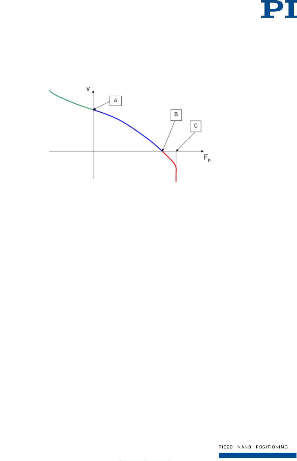
Velocities and step sizes when the drive is loaded
Figure 12: Velocity v as a function of the active force Fp (qualitative)
Fp: Active force
v: Velocity of the rod
Special conditions:
A: No load
B: Stop
C: Slippage
With increasing mass of the load (and thus the active force to be generated), the achievable step size of the
drive elements and thus also the maximum velocity of the rod decrease (see explanations of the operation of
the NEXLINE® drive in the manual of the controller). The relationships are qualitatively shown in the above
diagram.
In the unloaded state (point A), maximum step size and velocity are attained for horizontal mounting of linear
actuator and load when no pull force acts in the direction of the rod axis.
Pull forces acting on the rod (e.g. gravity in the case of vertical mounting or, in relation to the horizontal line,
inclined mounting of the system) can support the rod motion and cause the velocity to increase further (area left
of point A).
On the contrary, the linear actuator applies the maximum active force to compensate for the maximum
permissible load (point B). In this state, the velocity drops to 0.
In the currentless state of the linear actuator, the rod is clamped (holding force; generated by the preloaded
piezo assemblies). Consequently, the position of a coupled load is held with a permissible load. If the holding
force is overcompensated by an impermissibly high load, the clamping effect of the piezo assemblies on the rod
is lost (slippage, point C).
Compared to the velocity, analog conditions result for the step sizes in normal operation (see graph, range to
the left of B).
User Manual
Page 29 / 33
2017-07-20
N216T0013, valid for N-216
Physik Instrumente (PI ) GmbH & Co. KG, Auf der Römerstraße 1, D-76228 Karlsruhe
Telefon +49 721 4846-0, Fax +49 721 4846-1019, Email info@pi.ws, www.pi.ws
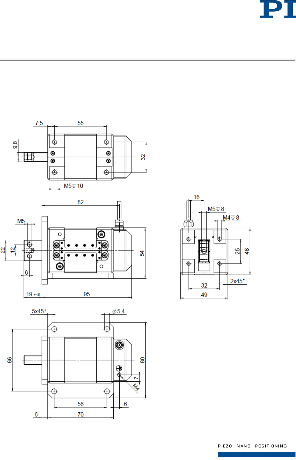
9.4 Dimensions
9.4.1 N-216 Actuator
The dimensions apply for any model of N-216. View partly with mounted flanges.
Dimensions in mm. Note that the decimal places are separated by a comma in the drawings.
Figure 13: Dimensions N-216, rod in center position
User Manual
Page 30 / 33
2017-07-20
N216T0013, valid for N-216
Physik Instrumente (PI ) GmbH & Co. KG, Auf der Römerstraße 1, D-76228 Karlsruhe
Telefon +49 721 4846-0, Fax +49 721 4846-1019, Email info@pi.ws, www.pi.ws
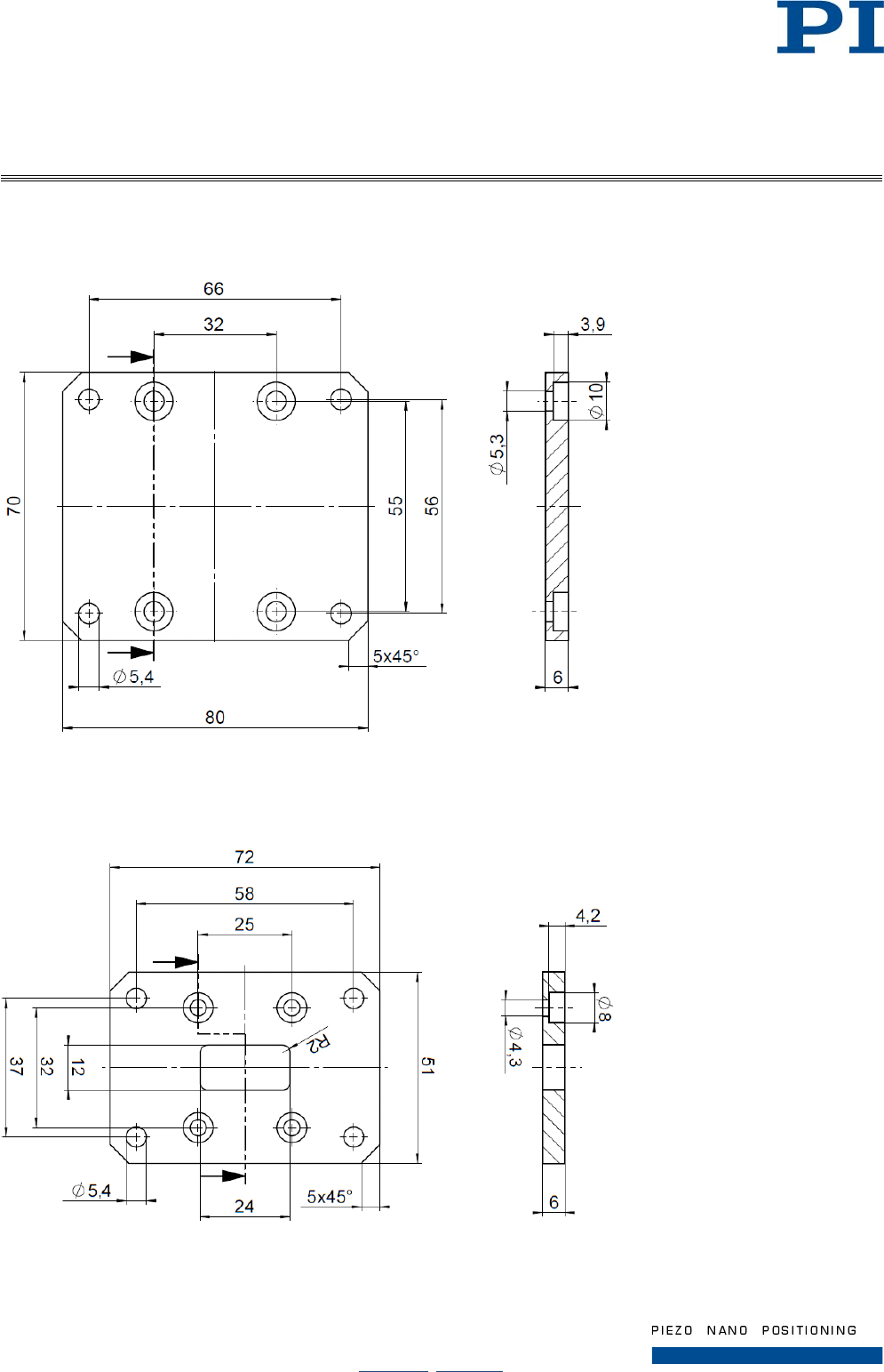
9.4.2 N216E0006 Mounting Flange A
Dimensions in mm. Note that the decimal places are separated by a comma in the drawings.
Figure 14: Dimensions of the mounting flange A (N216E0006)
9.4.3 N216E0008 Mounting Flange B
Dimensions in mm. Note that the decimal places are separated by a comma in the drawings.
Figure 15: Dimensions of the mounting flange B (N216E0008)
User Manual
Page 31 / 33
2017-07-20
N216T0013, valid for N-216
Physik Instrumente (PI ) GmbH & Co. KG, Auf der Römerstraße 1, D-76228 Karlsruhe
Telefon +49 721 4846-0, Fax +49 721 4846-1019, Email info@pi.ws, www.pi.ws
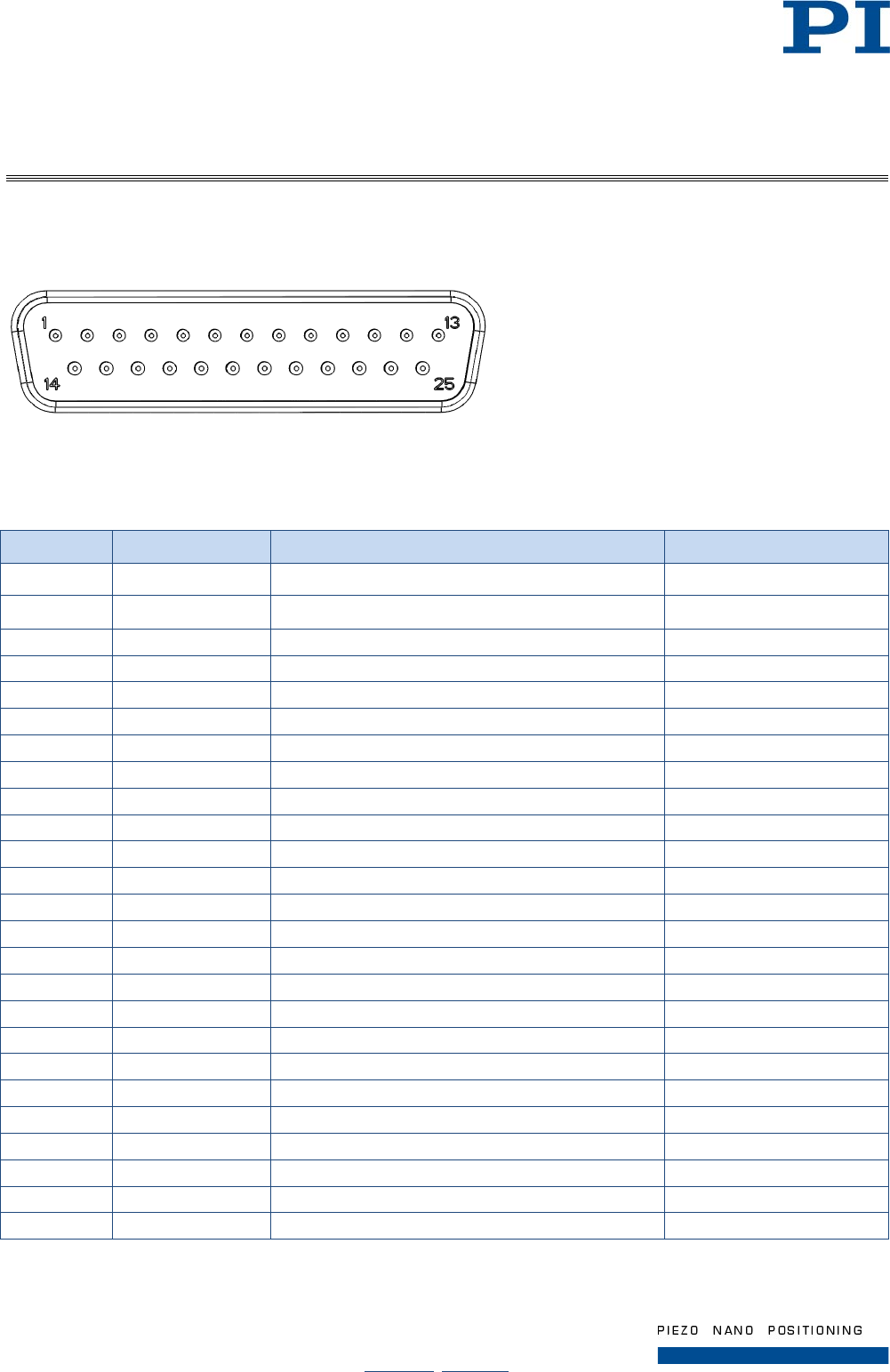
9.5 Pin Assignment (D-Sub 25, m)
Figure 16: D-Sub 25 connector (m), mating side
9.5.1 N-216.101 / N-216.201
Pin Signal* Function Direction
1 D1+ Supply voltage of shearing group 1 (-250 V to 250 V) Input
2 -
3 -
4 D2+ Supply voltage of shearing group 2 (-250 V to 250 V) Input
5
-
6
-
7
C1+
Supply voltage of clamping group 1 (-250 V to 250 V)
Input
8 -
9 -
10 C2+ Supply voltage of clamping group 2 (-250 V to 250 V) Input
11
-
12 -
13 -
14
-
15 D1- Ground of shearing group 1 GND
16 -
17 -
18 D2- Ground of shearing group 2 GND
19 -
20 -
21
C1-
Ground of clamping group 1
GND
22
-
23
-
24 C2- Ground of clamping group 2 GND
25
-
* The character "-" indicates that the corresponding pin is not connected.
User Manual
Page 32 / 33
2017-07-20
N216T0013, valid for N-216
Physik Instrumente (PI ) GmbH & Co. KG, Auf der Römerstraße 1, D-76228 Karlsruhe
Telefon +49 721 4846-0, Fax +49 721 4846-1019, Email info@pi.ws, www.pi.ws
9.5.2 N-216.1A1 / N-216.2A1
Pin Signal* Function Direction
1 D1+ Supply voltage of shearing group 1 (-250 V to 250 V) Input
2 +5V (Sensor) Supply voltage of encoder Input
3 +5V (Ref) Supply voltage of reference point switch Input
4 D2+ Supply voltage of shearing group 2 (-250 V to 250 V) Input
5 -
6 -
7 C1+
Supply voltage of clamping group 1 (-250 V to 250 V)
Input
8 GND (Sensor) Ground of encoder GND
9 GND (Ref) Ground of reference point switch GND
10 C2+ Supply voltage of clamping group 2 (-250 V to 250 V) Input
11 -
12 Ref- Reference point switch Output
13 Ref+ Reference point switch Output
14 -
15 D1- Ground of shearing group 1
16 Sin+ Encoder signal 1 (sine) Output
17 Sin- Encoder signal 1 (sine) Output
18 D2- Ground of shearing group 2 GND
19 Cos+ Encoder signal 2 (cosine) Output
20 Cos- Encoder signal 2 (cosine) Output
21 C1-
Ground of clamping group 1
GND
22 -
23 -
24 C2- Ground of clamping group 2 GND
25 -
* The character "-" indicates that the corresponding pin is not connected.
User Manual
Page 33 / 33
2017-07-20
N216T0013, valid for N-216
Physik Instrumente (PI ) GmbH & Co. KG, Auf der Römerstraße 1, D-76228 Karlsruhe
Telefon +49 721 4846-0, Fax +49 721 4846-1019, Email info@pi.ws, www.pi.ws
10 Old Equipment Disposal
In accordance with the applicable EU law, electrical and electronic equipment may not be disposed of with
unsorted municipal wastes in the member states of the EU.
When disposing of your old equipment, observe the international, national and local rules and regulations.
To meet the manufacturer’s product responsibility with regard to this product, Physik Instrumente (PI) GmbH &
Co. KG ensures environmentally correct disposal of old PI equipment that was first put into circulation after 13
August 2005, free of charge.
If you have old PI equipment, you can send it postage-free to the following address:
Physik Instrumente (PI) GmbH & Co. KG
Auf der Römerstr. 1
D-76228 Karlsruhe, Germany
11 EU Declaration of Conformity
For the N-216, an EC Declaration of Conformity has been issued in accordance with the following European
directives:
• Low Voltage Directive
• EMC Directive
• RoHS Directive
The applied standards certifying the conformity are listed below.
• Safety (Low Voltage Directive): EN 61010-1
• EMC: EN 61326-1
• RoHS: 50581
