Physik Instrumente PI CAT125E R3 Piezoelectric Ceramic Products
PI_CAT125E_R3_Piezoelectric_Ceramic_Products Fundamentals of Piezo Technology
User Manual: Physik Instrumente Catalogs, Brochures & Certificates
Open the PDF directly: View PDF ![]() .
.
Page Count: 44
PIEZO TECHNOLOGY
FUNDAMENTALS, CHARACTERISTICS AND APPLICATIONS
PIEZOCERAMIC
MATERIALS
COMPONENTS
INTEGRATION
Piezoelectric
Ceramic Products
FUNDAMENTALS, CHARACTERISTICS AND APPLICATIONS

2
WWW.PICERAMIC.COM
Contents
PI Ceramic – Leaders in Piezoelectric Technology .....................................3
Product Overview ...............................................................6
Fundamentals of Piezo Technology
Piezoelectric Effect and Piezo Technology ...........................................8
Electromechanics ...............................................................10
Dynamic Behavior ..............................................................12
Piezo Ceramics – Materials, Components, Products
Material Properties and Classification ..............................................14
Soft and Hard Piezo Ceramics ..................................................14
Lead-Free Materials ..........................................................15
Overview ...................................................................16
Material Data ..................................................................18
Temperature Dependence of the Coefficients .....................................20
Manufacturing Technology
Pressing Technology .........................................................22
Co-firing, Tape Technology, Multilayer ..........................................23
Flexibility in Shape and Design .................................................24
PICMA® Multilayer Actuators with Long Lifetime ..................................25
Metallization and Assembling Technology .......................................26
Piezo Ceramic Components: Dimensions ...........................................27
Testing Procedures .............................................................30
Integrated Components, Sub-Assemblies ...........................................31
Applications
Application Examples for Piezoceramic Elements ....................................32
Pumping and Dosing Techniques with Piezo Drives ................................33
Ultrasound Applications in Medical Engineering ..................................34
Ultrasonic Sensors ...........................................................35
Piezoelectric Actuators ........................................................37
Vibration Control ............................................................39
Adaptronics .................................................................40
Energy from Vibration – Energy Harvesting ......................................40
Ultrasonic Machining of Materials ..............................................41
Sonar Technology and Hydroacoustics .........................................41
PI Milestones ..................................................................42
Imprint
PI Ceramic GmbH, Lindenstrasse, 07589 Lederhose, Germany
Registration: HRB 203.582, Jena local court
VAT no.: DE 155932487
Executive board: Albrecht Otto, Dr. Peter Schittenhelm, Dr. Karl Spanner
Phone +49 36604-882-0, Fax +49-36604-882-4109
info@piceramic.com, www.piceramic.com
Although the information in this document has been compiled with the greatest care, errors cannot be ruled out
completely. Therefore, we cannot guarantee for the information being complete, correct and up to date. Illustrati-
ons may differ from the original and are not binding. PI reserves the right to supplement or change the information
provided without prior notice. All contents, including texts, graphics, data etc., as well as their layout, are subject to
copyright and other protective laws. Any copying, modification or redistribution in whole or in parts is subject to a
written permission of PI. The following company names and brands are registered trademarks of Physik Instrumente
(PI) GmbH & Co. KG : PI®, PIC®, NanoCube®, PICMA®, PILine®, NEXLINE®, PiezoWalk®, NEXACT®, Picoactuator®, PIn-
ano®, PIMag®. The following company names or brands are the registered trademarks of their owners: μManager,
LabVIEW, Leica, Linux, MATLAB, MetaMorph, Microsoft, National Instruments, Nikon, Olympus, Windows, Zeiss.

3
PIEZO TECHNOLOGY
Core Competences
of PI Ceramic
! Standard piezo com-
ponents for actuators,
ultrasonic and sensor
applications
! System solutions
! Manufacturing of piezo-
electric components of
up to several million
units per year
! Development of
custom-engineered
solutions
! High degree of flexibi-
lity in the engineering
process, short lead
times, manufacture of
individual units and
very small quantities
! All key technologies
and state-of-the-art
equipment for ceramic
production in-house
! Certified in accordance
with ISO 9001,
ISO 14001 and OHSAS
18001
PI Ceramic is one of the world’s market lead -
ers for piezoelectric actuators and sensors. PI
Ceramic provides everything related to piezo
ceramics, from the material and components
right through to the complete integration.
PI Ceramic provides system solutions for
research and industry in all high-tech mar-
kets including medical engineering, mechan-
ical engineer ing and automobile manufac-
ture, or semiconductor technology.
Materials Research and Development
PI Ceramic develops all its piezoceramic
materials itself. To this end PI Ceramic main-
tains its own laboratories, prototype manu-
facture as well as measurement and testing
stations. Moreover, PI Ceramic works with
leading universities and research institutions
at home and abroad in the field of piezoelec-
tricity.
Flexible Production
In addition to the broad spectrum of standard
products, the fastest possible realization of
customer-specific requirements is a top pri-
ority. Our pressing and multilayer technology
enables us to shape products with a short
lead time. We are able to manufacture indi-
vidual prototypes as well as high-volume
production runs. All processing steps are
undertaken in-house and are subject to con-
tinuous controls, a process which ensures
quality and adherence to deadlines.
Certified Quality
Since 1997, PI Ceramic has been certified
according to the ISO 9001 standard, where
the emphasis is not only on product quali-
ty but primarily on the expectations of the
customer and his satisfaction. PI Ceramic
is also certified according to the ISO 14001
(environmental management) and OHSAS
18001 (occupational safety) standards,
which taken together, form an Integrated
Management System (IMS). PI Ceramic is
a subsidiary of Physik Instrumente (PI) and
develops and produces all piezo actuators for
PI’s nanopositioning systems. The drives for
PILine® ultrasonic piezomotors and NEXLINE®
high-load stepping drives also originate from
PI Ceramic.
LEADERS IN PIEZOELECTRIC TECHNOLOGY
PI Ceramic
Company building of PI Ceramic in Lederhose, Thuringia, Germany.

4
WWW.PICERAMIC.COM
OUR MISSION
Reliability and Close Contact with our Customers
PI Ceramic provides
! Piezoceramic materials
(PZT)
! Piezoceramic
components
! Customized and appli-
cation-specific ultrasonic
transducers/transducers
! PICMA® monolithic
multilayer piezo actuators
!
Miniature piezo actuators
! PICMA® multilayer
bender actuators
! PICA high-load piezo
actuator
! PT Tube piezo actuators
! Preloaded actuators
with casing
! Piezocomposites –
DuraAct patch
transducers
Our aim is to maintain high, tested qual-
ity for both our standard products and for
custom-engineered components. We want
you, our customers, to be satisfied with the
performance of our products. At PI Ceramic,
customer service starts with an initial infor-
mative discussion and extends far beyond
the shipping of the products.
Advice from Piezo Specialists
You want to solve complex problems – we
won’t leave you to your own devices. We
use our years of experience in planning,
developing, designing and the production
of individual solutions to accompany you
from the initial idea to the finished product.
We take the time necessary for a detailed
understanding of the issues and work out
a comprehensive and optimum solution at
an early stage with either existing or new
technologies.
PI Ceramic supplies piezo-ceramic solutions
to all important high-tech markets:
! Industrial automation
! Semiconductor industry
! Medical engineering
! Mechanical and precision engineering
! Aviation and aerospace
! Automotive industry
! Telecommunications
After-Sales Service
Even after the sale has been completed,
our specialists are available to you and can
advise you on system upgrades or technical
issues. This is how we at PI Ceramic achieve
our objective: Long-lasting business rela-
tions and a trusting communication with
customers and suppliers, both of which
are more important than any short-term
success.

5
PIEZO TECHNOLOGY
STATE-OF-THE-ART MANUFACTURING TECHNOLOGY
Experience and Know-How
Developing and manufacturing piezoceram-
ic components are very complex processes.
PI Ceramic has many years of experience in
this field and has developed sophisticated
manufacturing methods. Its machines and
equipment are state of the art.
Rapid Prototyping
The requirements are realized quickly and
flexibly in close liaison with the customer.
Prototypes and small production runs of
custom-engineered piezo components are
available after very short processing times.
The manufacturing conditions, i.e. the
composition of the material or the sintering
temperature, for example, are individually
adjusted to the ceramic material in order to
achieve optimum material parameters.
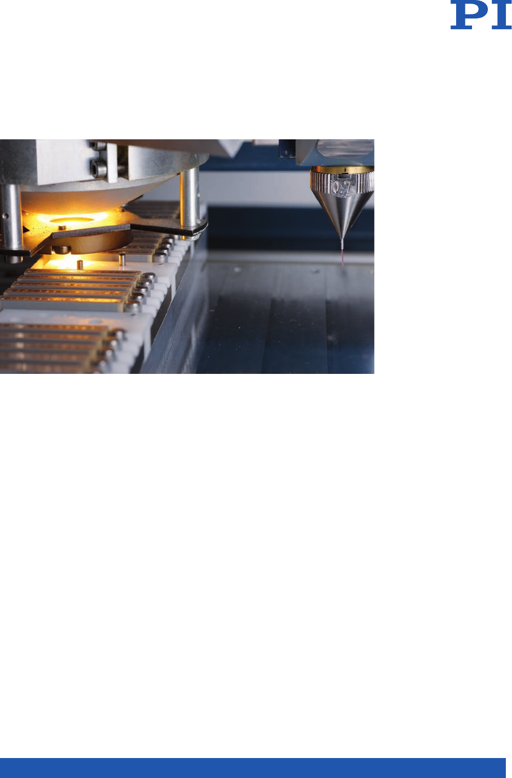
Precision Machining Technology
PI Ceramic uses machining techniques from
the semiconductor industry to machine the
sensitive piezoceramic elements with a
particularly high degree of precision. Spe-
cial milling machines accurately shape the
components when they are still in the “green
state“, i.e. before they are sintered. Sintered
ceramic blocks are machined with precision
saws like the ones used to separate indi-
vi dual wafers. Very fine holes, structured
ceramic surfaces, even complex, three-
dimen sional contours can be produced.
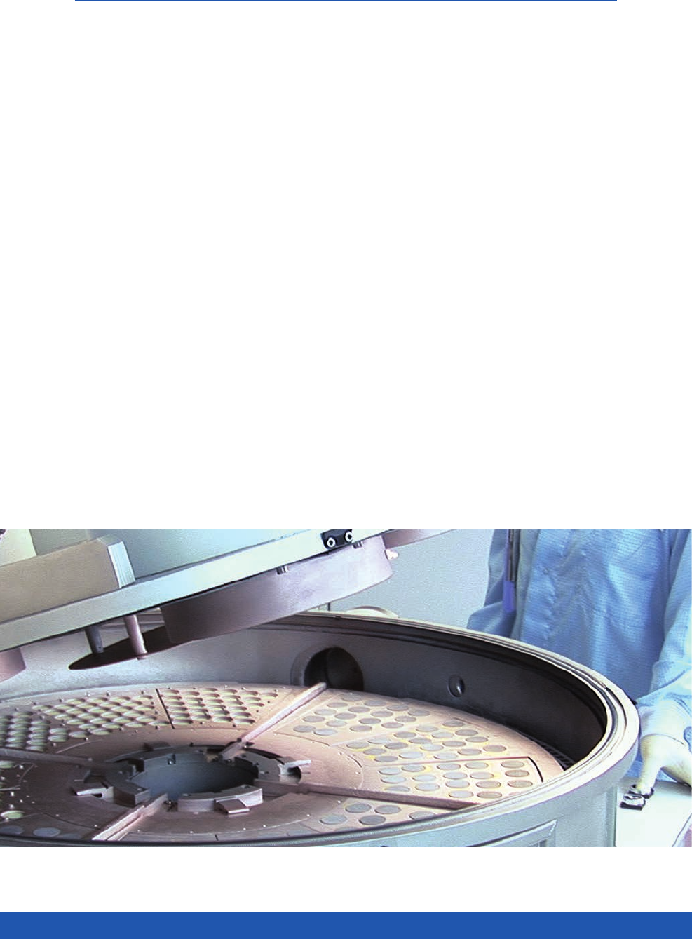
Automated Series Production –
Advantage for OEM Customers
An industrial application often requires large
quantities of custom-engineered compo-
nents. At PI Ceramic, the transition to large
production runs can be achieved in a reliable
and low-cost way while maintaining the high
quality of the products. PI Ceramic has the ca-
pacity to produce and process medium-sized
and large production runs in linked automat-
ed lines. Automatic screen printers and the
latest PVD units are used to metallize the
ceramic parts.
Automated processes optimize throughput
6
WWW.PICERAMIC.COM
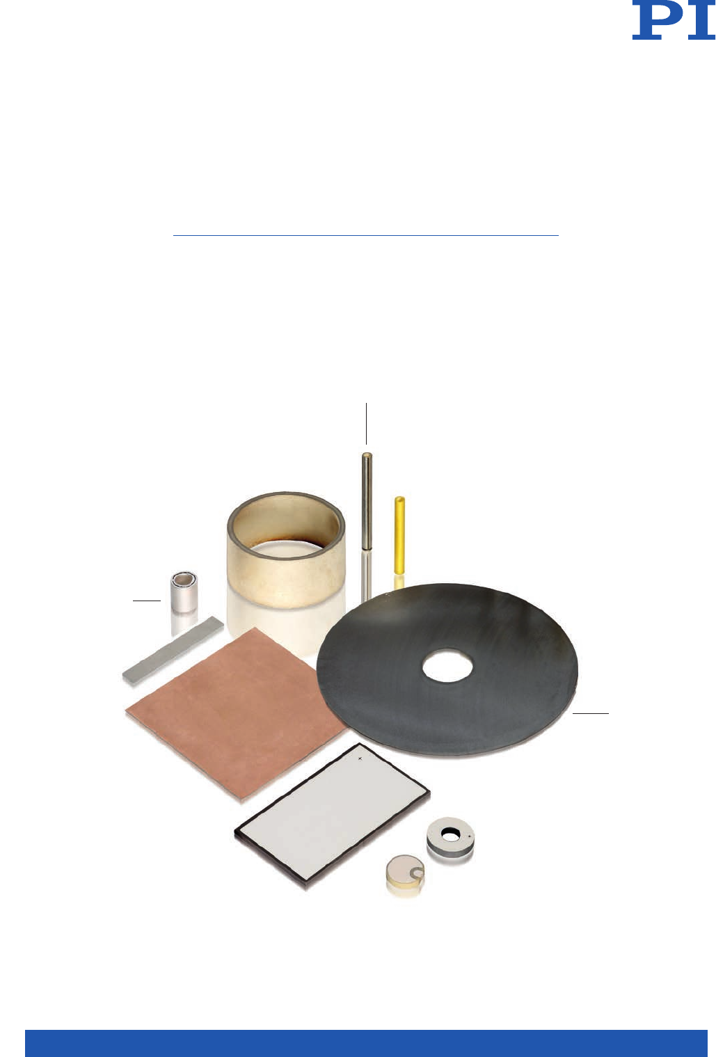
Piezoelectric Components
! Various different versions in many dif-
ferent geometries such as disks, plates,
tubes, customized shapes
! High resonant frequencies to 20 MHz
OEM Adaptations
! Piezo transducers for ultrasonic
applications
! Assembly of complete transducer
components
! 2D or line arrays
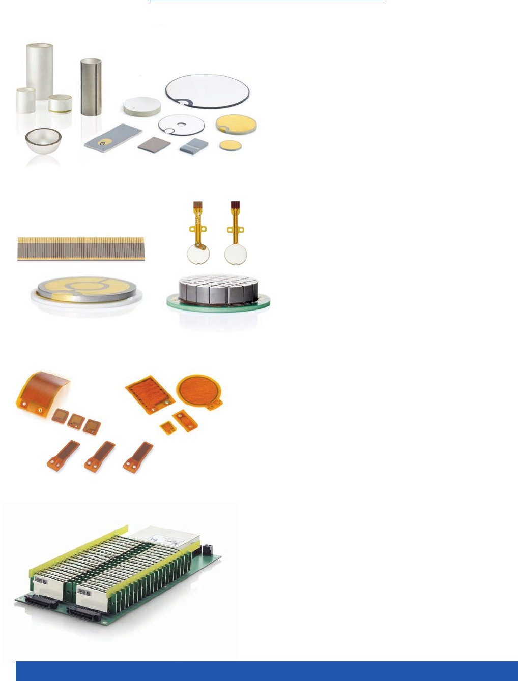
DuraAct Piezo Patch Transducers
! Actuator or sensor, structural health
monitoring
! Bendable and robust, preloaded due to
lamination
Control Electronics
! Different performance classes
! OEM modules and benchtop devices
IN-HOUSE DEVELOPMENT AND PRODUCTION
Product Overview
7
PIEZO TECHNOLOGY
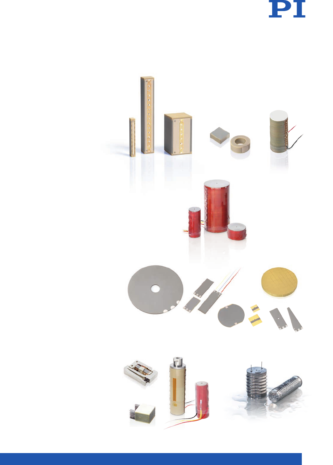
PICMA® Multilayer Piezo Actuators
! Low piezo voltage to 120 V
! High stiffness
! Travel ranges to 100 µm
PICA High-Load Actuators
! Travel ranges to 300 µm
! Forces to 100 kN
PICMA® Multilayer Bending Actuators
! Bidirectional displacement to 2 mm
! Low operating voltage to 60 V
! Contractors, variable contours
Piezo Actuators with
Customized Equipment
! For use in a harsh environment
! Position and temperature monitoring
! For cryogenic temperatures
8
WWW.PICERAMIC.COM
Piezoelectric Effect and Piezo Technology
Piezoelectric materials convert electrical ener-
gy into mechanical energy and vice versa.
The piezoelectric effect is now used in many
everyday products such as lighters, loud-
speakers and signal transducers. Piezo actua-
tor technology has also gained acceptance
in automotive technology, because piezo-
controlled injection valves in combustion
engines reduce the transition times and signi-
ficantly improve the smoothness and exhaust
gas quality.
From the Physical Effect to Industrial Use
The word “piezo“ is derived from the Greek
word for pressure. In 1880 Jacques and Pier-
re Curie discovered that pressure generates
electrical charges in a number of crystals
such as Quartz and Tourmaline; they called
this phenomenon the “piezoelectric effect“.
Later they noticed that electrical fields can
deform piezoelectric materials. This effect is
called the “inverse piezoelectric effect“. The
industrial breakthrough came with piezo-
electric ceramics, when scientists discovered
that Barium Titanate assumes piezoelectric
characteristics on a useful scale when an
electric field is applied.
Piezoelectric Ceramics …
The piezoelectric effect of natural mono-
crystalline materials such as Quartz, Tour-
maline and Seignette salt is relatively small.
Polycrystalline ferroelectric ceramics such as
Barium Titanate (BaTiO3) and Lead Zirconate
Titanate (PZT) exhibit larger displacements
or induce larger electric voltages. PZT pie-
zo ceramic materials are available in many
modifications and are most widely used
for actuator or sensor applications. Special
dopings of the PZT ceramics with e.g. Ni, Bi,
Sb, Nb ions make it possible to specifically
optimize piezoelectric and dielectric parame-
ters.
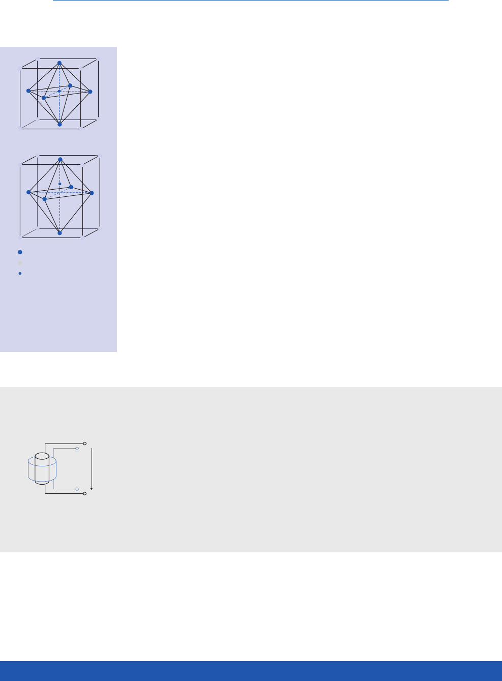
… with Polycrystalline Structure
At temperatures below the Curie tempera-
ture, the lattice structure of the PZT crystal-
lites becomes deformed and asymmetric.
This brings about the formation of dipoles
and the rhombohedral and tetragonal cry-
stallite phases which are of interest for pie-
zo technology. The ceramic exhibits spon-
taneous polarization (see Fig. 1). Above the
Curie temperature the piezoceramic material
loses its piezoelectric properties.
Direct Piezoelectric Effect
Mechanical stresses arising as the result
of an external force that act on the piezo-
electric body induce displacements of the
electrical dipoles. This generates an elec-
tric field, which produces a corresponding
electric voltage. This direct piezoelectric
effect is also called the sensor or generator
effect.
Inverse Piezoelectric Effect
When an electric voltage is applied to an
unrestrained piezoceramic component it
brings about a geometric deformation. The
movement achieved is a function of the
polarity, of the voltage applied and the
direction of the polarization in the device.
The application of an AC voltage produ-
ces an oscillation, i.e. a periodic change of
the geometry, for example the increase or
reduction of the diameter of a disk. If the
body is clamped, i.e. free deformation is
constrained, a mechanical stress or force
is generated. This effect is frequently also
called the actuator or motor effect.
L
+
o
∆L
Polarisation
axis
C1
L1
C0
Impendanz Z
Frequenz f
fmfn
∆ L
V0
(2)
+
–
+
–
+
–
+
–
+
–
+
–
+
–
+
–
+
–
+
–
+
–
+
–
(3)
+
–
+
–
+
–
+
–
+
–
+
–
+
–
+
–
+
–
+
–
+
–
+
–
(1)
+
–
+
–
+
–
+
–
+
–
+
–
+
–
+
–
U
+
–
P C/m2
E kV/cm
Ps
Ec
-Ec
Pr
-Pr
-Ps
+
–
+
–
+
–
+
–
+
–
+
–
+
–
+
–
+
–
+
–
3
1(r)
3
3(r)
Radialschwingung
Dickenschwingung
Radialschwingung
Dickenschwingung
Längsschwingung
Radialschwingung
Dickenschwingung
OD
ID
TH P
(1)
(2)
O2
Pb
Ti, Zr
Längsschwingung
Dickenschwingung
3
1(r)
1
3
2
TH
5
6
3
1
2
3
2
TH
5
6
1
P
TH
W
LP
TH
L
W
P
L
W
TH
P
TH
W
L
L
P
L
P
D
P
TH
OD
P
L
OD
ID
OD
TH TH
OD
(Z)
3
2(Y)
(X)1
6
5
4
P
(Z)
3
2(Y)
(X)1
6
5
4
P
P
WTH
L
R1
Fig. 1.
(1)
Unit cell with symmetrical,
cubic Perovskite structure,
T >
T
C
(2) Tetragonally distorted unit
cell, T<T
C
L
+
o
∆L
Polarisation
axis
C1
L1
C0
Impendanz Z
Frequenz f
fmfn
∆ L
V0
(2)
+
–
+
–
+
–
+
–
+
–
+
–
+
–
+
–
+
–
+
–
+
–
+
–
(3)
+
–
+
–
+
–
+
–
+
–
+
–
+
–
+
–
+
–
+
–
+
–
+
–
(1)
+
–
+
–
+
–
+
–
+
–
+
–
+
–
+
–
U
+
–
P C/m2
E kV/cm
Ps
Ec
-Ec
Pr
-Pr
-Ps
+
–
+
–
+
–
+
–
+
–
+
–
+
–
+
–
+
–
+
–
3
1(r)
3
3(r)
Radialschwingung
Dickenschwingung
Radialschwingung
Dickenschwingung
Längsschwingung
Radialschwingung
Dickenschwingung
OD
ID
TH P
(1)
(2)
O2
Pb
Ti, Zr
Längsschwingung
Dickenschwingung
3
1(r)
1
3
2
TH
5
6
3
1
2
3
2
TH
5
6
1
P
TH
W
LP
TH
L
W
P
L
W
TH
P
TH
W
L
L
P
L
P
D
P
TH
OD
P
L
OD
ID
OD
TH TH
OD
(Z)
3
2(Y)
(X)1
6
5
4
P
(Z)
3
2(Y)
(X)1
6
5
4
P
P
WTH
L
R1
9
PIEZO TECHNOLOGY
Fig. 2. Electric dipoles in
domains:
(1) unpolarized,
ferroelectric ceramic,
(2) during and
(3) after the poling
(piezoelectric ceramic).
Ferroelectric Domain Structure
One effect of the spontaneous polarization
is that the discrete PZT crystallites become
piezoelectric. Groups of unit cells with the
same orientation are called ferroelectric
domains. Because of the random distribu-
tion of the domain orientations in the cera-
mic material no macroscopic piezoelectric
be havior is observable. Due to the ferro-
electric nature of the material, it is possible to
force permanent reorientation and alignment
of the differ ent domains using a strong elec-
tric field. This process is called poling (see
Fig. 2).
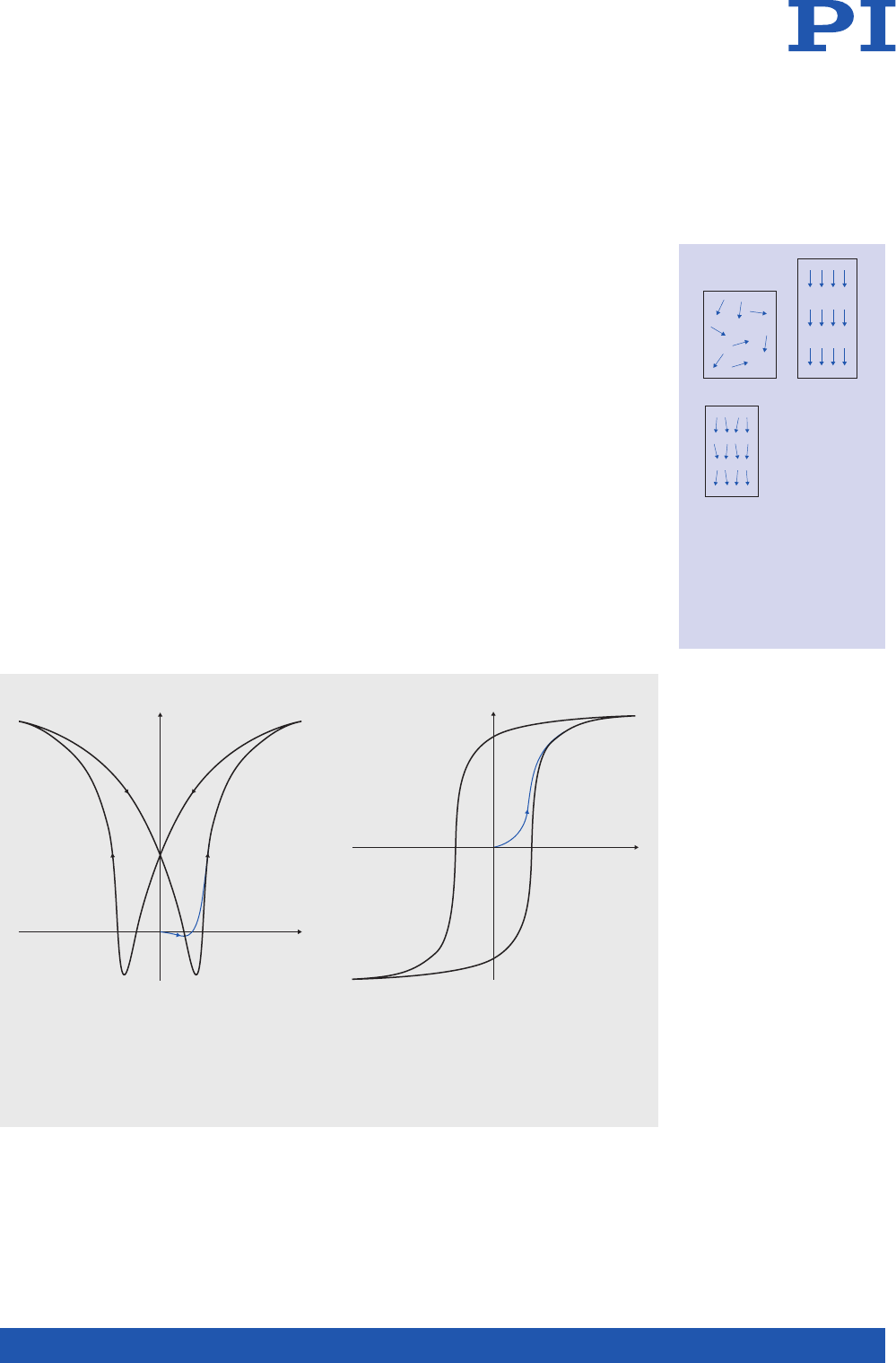
Polarization of the Piezoceramics
The poling process results in a remnant
polarization Pr which coincides with a
remnant expansion of the material and
which is degraded again when the mecha-
nical, thermal and electrical limit values of
the material are exceeded (see Fig. 3). The
ceramic now exhibits piezoelectric pro-
perties and will change dimensions when
an electric voltage is applied. Some PZT
ceramics must be poled at an elevated tem-
perature.
When the permissible operating tempe-
rature is exceeded, the polarized ceramic
depolarizes. The degree of depolarization is
depending on the Curie temperature of the
material.
An electric field of sufficient strength can
reverse the polarization direction (see Fig.
4). The link between mechanical and electri-
cal parameters is of crucial significance for
the widespread technical utilization of piezo
ceramics.
Fig. 3. The butterfly curve shows the typical
deformation of a ferroelectric “soft“ piezo ceramic
material when a bipolar voltage is applied.
The displacement of the ceramic here is based
exclusively on solid state effects, such as the ali-
gnment of the dipoles. The motion produced
is therefore frictionless and non-wearing.
Fig. 4. An opposing electric field will only
depolarize the material if it exceeds the
coercivity strength Ec. A further increase in the
opposing field leads to repolarization, but in
the opposite direction.
L
+
o
∆L
Polarisation
axis
C1
L1
C0
Impendanz Z
Frequenz f
fmfn
∆ L
V0
(2)
+
–
+
–
+
–
+
–
+
–
+
–
+
–
+
–
+
–
+
–
+
–
+
–
(3)
+
–
+
–
+
–
+
–
+
–
+
–
+
–
+
–
+
–
+
–
+
–
+
–
(1)
+
–
+
–
+
–
+
–
+
–
+
–
+
–
+
–
U
+
–
P C/m2
E kV/cm
Ps
Ec
-Ec
Pr
-Pr
-Ps
+
–
+
–
+
–
+
–
+
–
+
–
+
–
+
–
+
–
+
–
3
1(r)
3
3(r)
Radialschwingung
Dickenschwingung
Radialschwingung
Dickenschwingung
Längsschwingung
Radialschwingung
Dickenschwingung
OD
ID
TH P
(1)
(2)
O2
Pb
Ti, Zr
Längsschwingung
Dickenschwingung
3
1(r)
1
3
2
TH
5
6
3
1
2
3
2
TH
5
6
1
P
TH
W
LP
TH
L
W
P
L
W
TH
P
TH
W
L
L
P
L
P
D
P
TH
OD
P
L
OD
ID
OD
TH TH
OD
(Z)
3
2(Y)
(X)1
6
5
4
P
(Z)
3
2(Y)
(X)1
6
5
4
P
P
WTH
L
R1
L
+
o
∆L
Polarisation
axis
C1
L1
C0
Impendanz Z
Frequenz f
fmfn
∆ L
V0
(2)
+
–
+
–
+
–
+
–
+
–
+
–
+
–
+
–
+
–
+
–
+
–
+
–
(3)
+
–
+
–
+
–
+
–
+
–
+
–
+
–
+
–
+
–
+
–
+
–
+
–
(1)
+
–
+
–
+
–
+
–
+
–
+
–
+
–
+
–
U
+
–
P C/m2
E kV/cm
Ps
Ec
-Ec
Pr
-Pr
-Ps
+
–
+
–
+
–
+
–
+
–
+
–
+
–
+
–
+
–
+
–
3
1(r)
3
3(r)
Radialschwingung
Dickenschwingung
Radialschwingung
Dickenschwingung
Längsschwingung
Radialschwingung
Dickenschwingung
OD
ID
TH P
(1)
(2)
O2
Pb
Ti, Zr
Längsschwingung
Dickenschwingung
3
1(r)
1
3
2
TH
5
6
3
1
2
3
2
TH
5
6
1
P
TH
W
LP
TH
L
W
P
L
W
TH
P
TH
W
L
L
P
L
P
D
P
TH
OD
P
L
OD
ID
OD
TH TH
OD
(Z)
3
2(Y)
(X)1
6
5
4
P
(Z)
3
2(Y)
(X)1
6
5
4
P
P
WTH
L
R1
S
E
P
E
Ec
-Ec
Pr
-Pr
Ps
-Ps
S
E
P
E
Ec
-Ec
Pr
-Pr
Ps
-Ps
10
WWW.PICERAMIC.COM
FUNDAMENTAL EQUATIONS AND PIEZOELECTRIC COEFFICIENTS
Electromechanics
Polarized piezoelectric materials are charac-
terized by several coefficients and relation-
ships. In simplified form, the basic relation-
ships between the electrical and elastic
properties can be represented as follows :
D = d T + εTE
S = sET + d E
These relationships apply only to small elec -
trical and mechanical amplitudes, so-called
small signal values. Within this range the
relationships between the elastic deformati-
on (S) or stress (T) components and the com-
ponents of the electric field E or the electric
flux density D are linear.
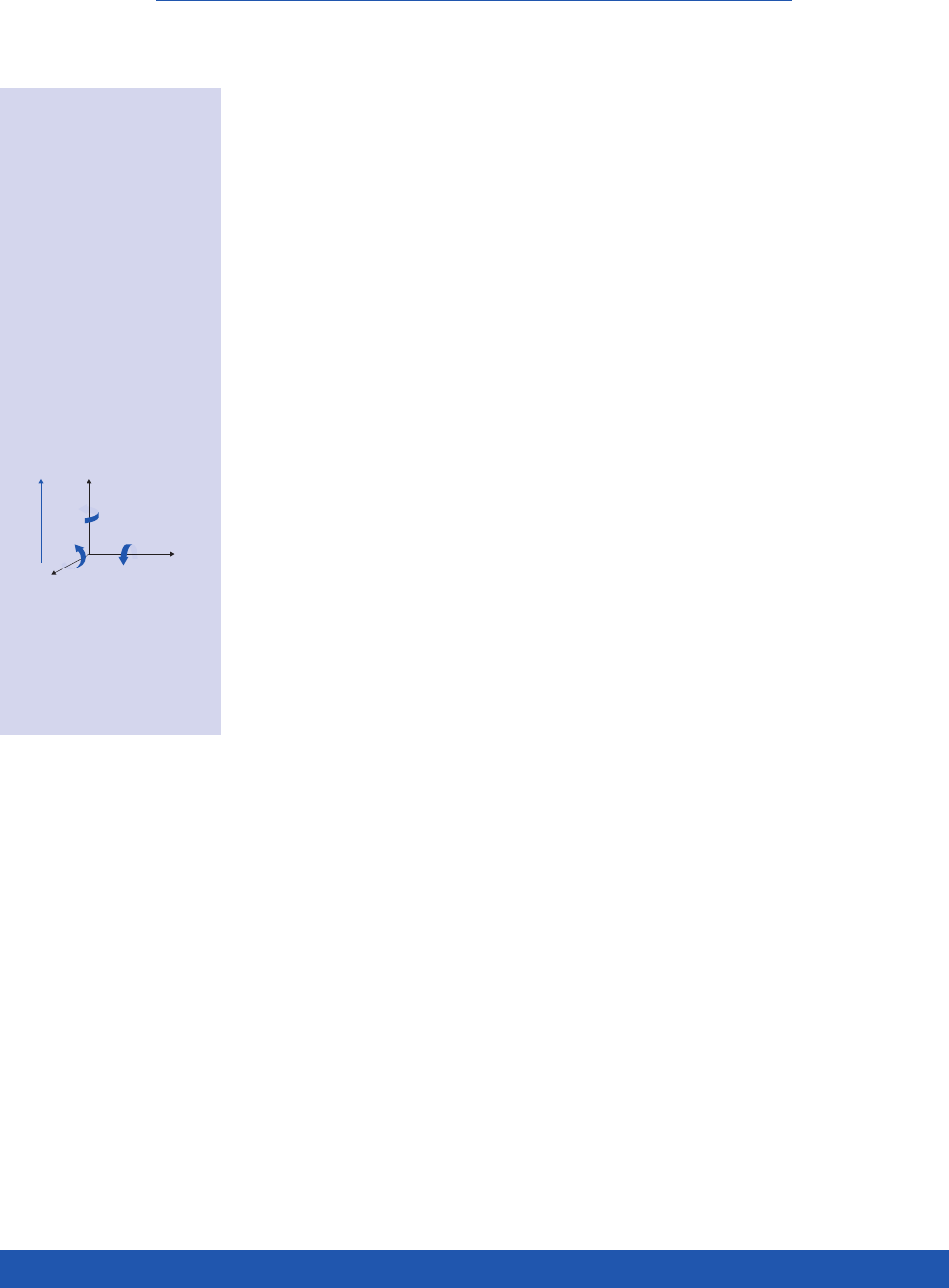
Assignment of Axis
The directions are designated by 1, 2, and
3, corresponding to axes X, Y and Z of the
classical right-hand orthogonal axis set. The
rotational axes are designated with 4, 5 and 6
(see Fig. 5). The direction of polarization (axis
3) is established during the poling process
by a strong electrical field applied between
the two electrodes. Since the piezoelectric
material is anisotropic, the corresponding
physical quantities are described by tensors.
The piezoelectric coefficients are therefore
indexed accordingly.
Permittivity ε
The relative permittivity, or relative dielec-
tric coefficient, ε is the ratio of the absolute
permittivity of the ceramic material and the
permittivity in vacuum (ε
0
= 8.85 x 10⁻¹² F/m),
where the absolute permittivity is a measu-
re of the polarizability. The dependency of
the permittivity from the orientation of the
electric field and the flux density is described
by indexes.
Examples
ε
33
T permittivity value in the polarizati-
on direction when an electric field is
applied parallel to the direction of the
polarity (direction 3), under conditions
of constant mechanical stress (T = 0:
“
free
“
permittivity).
ε
11
S permittivity if the electric field and
dielectric displacement are in direc-
tion 1 at constant deformation (S = 0:
“clamped“ permittivity).
Piezoelectric Charge or Strain Coefficient,
Piezo Modulus d
ij
The piezo modulus is the ratio of induced
electric charge to mechanical stress or of
achievable mechanical strain to electric field
applied (T = constant).
Example
d
33
mechanical strain induced per unit of
electric field applied in V/m or charge
density in C/m2 per unit pressure in N/
m2, both in polarization direction.
Piezoelectric Voltage Coefficient gij
The piezoelectric voltage coefficient g is
the ratio of electric field E to the effective
mechanical stress T. Dividing the respec-
tive piezoelectric charge coefficient dij by
the corresponding permittivity gives the
corresponding gij coefficient.
Example
g
31
describes the electric field induced in
direction 3 per unit of mechanical stress
acting in direction 1. Stress = force per
unit area, not necessarily orthogonal.
D electric flux density,
or dielectric
displacement
T mechanical stress
E electric field
S mechanical strain
d piezoelectric charge
coefficient
ε
T dielectric permittivity
(for T = constant)
sE elastic coefficient
(for E = constant)
Fig. 5. Orthogonal
coordinate system to
describe the properties
of a poled piezoelectric
ceramic. The polarization
vector is parallel to the
3 (Z)-axis.
L
+
o
∆L
Polarisation
axis
C1
L1
C0
Impendanz Z
Frequenz f
fmfn
∆ L
V0
(2)
+
–
+
–
+
–
+
–
+
–
+
–
+
–
+
–
+
–
+
–
+
–
+
–
(3)
+
–
+
–
+
–
+
–
+
–
+
–
+
–
+
–
+
–
+
–
+
–
+
–
(1)
+
–
+
–
+
–
+
–
+
–
+
–
+
–
+
–
U
+
–
P C/m2
E kV/cm
Ps
Ec
-Ec
Pr
-Pr
-Ps
+
–
+
–
+
–
+
–
+
–
+
–
+
–
+
–
+
–
+
–
3
1(r)
3
3(r)
Radialschwingung
Dickenschwingung
Radialschwingung
Dickenschwingung
Längsschwingung
Radialschwingung
Dickenschwingung
OD
ID
TH P
(1)
(2)
O2
Pb
Ti, Zr
Längsschwingung
Dickenschwingung
3
1(r)
1
3
2
TH
5
6
3
1
2
3
2
TH
5
6
1
P
TH
W
LP
TH
L
W
P
L
W
TH
P
TH
W
L
L
P
L
P
D
P
TH
OD
P
L
OD
ID
OD
TH TH
OD
(Z)
3
2(Y)
(X)1
6
5
4
P
(Z)
3
2(Y)
(X)1
6
5
4
P
P
WTH
L
R1

11
PIEZO TECHNOLOGY
Elastic Compliance sij
The elastic compliance coefficient s is the
ratio of the relative deformation S to the
mechanical stress T. Mechanical and elec-
trical energy are mutually dependent, the
electrical boundary conditions such as
the electric flux density D and field E must
therefore be taken into consideration.
Examples
s33
E the ratio of the mechanical strain in
direction 3 to the mechanical stress
in the direction 3, at constant electric
field (for E = 0: short circuit).
s55
D the ratio of a shear strain to the
effective shear stress at constant
dielectric displacement (for D = 0: open
electrodes).
The often used elasticity or Young’s mo-
dulus Yij corresponds in a first approximati-
on to the reciprocal value of the correspon-
ding elasticity coefficient.
Frequency Coefficient Ni
The frequency coefficient N describes
the relationship between the geometrical
di mension A of a body and the corresponding
(series) resonance frequency. The indices
designate the corresponding direction of
oscillation N = fsA.
Examples
N3 describes the frequency coefficient
for the longitudinal oscillation of a
slim rod polarized in the longitudinal
direction.
N1 is the frequency coefficient for the
transverse oscillation of a slim rod
polarized in the 3-direction.
N5
is the frequency coefficient of the
thick ness
shear oscillation of a thin
disk.
NP is the frequency coefficient of the
planar oscillation of a round disk.
Nt is the frequency coefficient of the
thickness oscillation of a thin disk
polarized in the thickness direction.
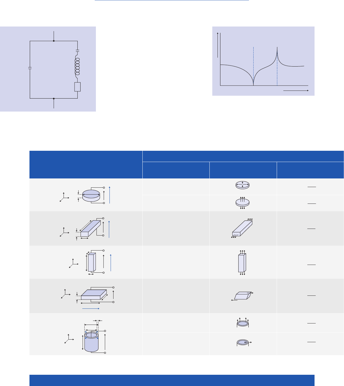
Mechanical Quality Factor Qm
The mechanical quality factor Q
m
character-
izes the “sharpness of the resonance“ of
a piezoelectric body or resonator and is
primarily determined from the 3 dB band-
width of the series resonance of the system
which is able to oscillate (see Fig. 7 typical
impedance curve). The reciprocal value
of the mechanical quality factor is the
mechanical loss factor, the ratio of effecti-
ve resistance to reactance in the equivalent
circuit diagram of a piezoelectric resonator at
resonancem (Fig. 6).
Coupling Factors k
The coupling factor k is a measure of how
the magnitude of the piezoelectric effect is
(n o t an efficiency factor!). It describes the
ability of a piezoelectric material to convert
electrical energy into mechanical energy and
vice versa. The coupling factor is determi-
ned by the square root of the ratio of stored
mechanical energy to the total energy ab-
sorbed. At resonance, k is a function of the
corresponding form of oscillation of the
piezoelectric body.
Examples
k33 the coupling factor for the longitudinal
oscillation.
k31 the coupling factor for the transverse
oscillation.
kP the coupling factor for the planar radial
oscillation of a round disk.
kt the coupling factor for the thickness
oscillation of a plate.
k15 the coupling factor for the thickness
shear oscillation of a plate.
12
WWW.PICERAMIC.COM
The electromechanical behavior of a piezo-
electric element excited to oscillations can
be represented by an electrical equivalent
circuit diagram (s. Fig. 6). C0 is the capaci-
tance of the dielectric. The series circuit, con-
sisting of C1, L1, and R1, describes the change
in the mechanical properties, such as elastic
deformation, effective mass (inertia) and
mechanical losses resulting from internal
friction. This description of the oscillatory
circuit can only be used for frequencies
in the vicinity of the mechanical intrinsic
resonance.
Most piezoelectric material parameters are
determined by means of impedance mea-
surements on special test bodies according
to the European Standard EN 50324-2 at
resonance.
Fig. 7. Typical impedance curve
Fig. 6. Equivalent circuit diagram
of a piezoelectric resonator
Thin disk
Plate
Rod
Shear plate
Tube
radial
thickness
transverse
longitudinal
thickness shear
transversal
thickness
Shape Oscillations Electrically Mechanically
induced induced
Type Mechanical Series resonance displacement voltage
deformation frequency (small signal) (small signal)
L
+
o
∆L
Polarisation
axis
C1
L1
C0
Impendanz Z
Frequenz f
fmfn
∆ L
V0
(2)
+
–
+
–
+
–
+
–
+
–
+
–
+
–
+
–
+
–
+
–
+
–
+
–
(3)
+
–
+
–
+
–
+
–
+
–
+
–
+
–
+
–
+
–
+
–
+
–
+
–
(1)
+
–
+
–
+
–
+
–
+
–
+
–
+
–
+
–
U
+
–
P C/m2
E kV/cm
Ps
Ec
-Ec
Pr
-Pr
-Ps
+
–
+
–
+
–
+
–
+
–
+
–
+
–
+
–
+
–
+
–
3
1(r)
3
3(r)
Radialschwingung
Dickenschwingung
Radialschwingung
Dickenschwingung
Längsschwingung
Radialschwingung
Dickenschwingung
OD
ID
TH P
(1)
(2)
O2
Pb
Ti, Zr
Längsschwingung
Dickenschwingung
3
1(r)
1
3
2
TH
5
6
3
1
2
3
2
TH
5
6
1
P
TH
W
LP
TH
L
W
P
L
W
TH
P
TH
W
L
L
P
L
P
D
P
TH
OD
P
L
OD
ID
OD
TH TH
OD
(Z)
3
2(Y)
(X)1
6
5
4
P
(Z)
3
2(Y)
(X)1
6
5
4
P
P
WTH
L
R1
L
+
o
∆L
Polarisation
axis
C1
L1
C0
Impedance Z
Frequency f
fmfn
∆ L
V0
(2)
+
–
+
–
+
–
+
–
+
–
+
–
+
–
+
–
+
–
+
–
+
–
+
–
(3)
+
–
+
–
+
–
+
–
+
–
+
–
+
–
+
–
+
–
+
–
+
–
+
–
(1)
+
–
+
–
+
–
+
–
+
–
+
–
+
–
+
–
U
+
–
P C/m2
E kV/cm
Ps
Ec
-Ec
Pr
-Pr
-Ps
+
–
+
–
+
–
+
–
+
–
+
–
+
–
+
–
+
–
+
–
3
1(r)
3
3(r)
Radialschwingung
Dickenschwingung
Radialschwingung
Dickenschwingung
Längsschwingung
Radialschwingung
Dickenschwingung
OD
ID
TH P
(1)
(2)
O2
Pb
Ti, Zr
Längsschwingung
Dickenschwingung
3
1(r)
1
3
2
TH
5
6
3
1
2
3
2
TH
5
6
1
P
TH
W
LP
TH
L
W
P
L
W
TH
P
TH
W
L
L
L
P
D
P
TH
OD
P
L
OD
ID
OD
TH TH
OD
(Z)
3
2(Y)
(X)1
6
5
4
P
(Z)
3
2(Y)
(X)1
6
5
4
P
P
WTH
L
R1
P
W
ƒs =NP
OD
ƒs =Nt
TH
ƒs =N1
L
ƒs =N3
L
ƒs =N5
TH
ƒs ≈Nt
TH
ƒs ≈N1
L
TH U
OD
OD >> TH
2
1
3
TH
W
L
U
L >> W >> TH
2
1
3LL ≈ W >> TH
L
W
U
TH
2
1
3
TH
W
L
UL >> W >> TH
2
1
3
U
L >> OD >> TH
L
OD
TH
ID
L
P
P
2
1
3
P
P
P
TH U
OD
OD >> TH
2
1
3
TH
W
L
U
L >> W >> TH
2
1
3LL ≈ W >> TH
L
W
U
TH
2
1
3
TH
W
L
UL >> W >> TH
2
1
3
U
L >> OD >> TH
L
OD
TH
ID
L
P
P
2
1
3
P
P
P
TH U
OD
OD >> TH
2
1
3
TH
W
L
U
L >> W >> TH
2
1
3LL ≈ W >> TH
L
W
U
TH
2
1
3
TH
W
L
UL >> W >> TH
2
1
3
U
L >> OD >> TH
L
OD
TH
ID
L
P
P
2
1
3
P
P
P
TH U
OD
OD >> TH
2
1
3
TH
W
L
U
L >> W >> TH
2
1
3LL ≈ W >> TH
L
W
U
TH
2
1
3
TH
W
L
UL >> W >> TH
2
1
3
U
L >> OD >> TH
L
OD
TH
ID
L
P
P
2
1
3
P
P
P
TH U
OD
OD >> TH
2
1
3
TH
W
L
U
L >> W >> TH
2
1
3LL ≈ W >> TH
L
W
U
TH
2
1
3
TH
W
L
UL >> W >> TH
2
1
3
U
L >> OD >> TH
L
OD
TH
ID
L
P
P
2
1
3
P
P
P
TH U
OD
OD >> TH
2
1
3
TH
W
L
U
L >> W >> TH
2
1
3LL ≈ W >> TH
L
W
U
TH
2
1
3
TH
W
L
UL >> W >> TH
2
1
3
U
L >> OD >> TH
L
OD
TH
ID
L
P
P
2
1
3
P
P
P
TH U
OD
OD >> TH
2
1
3
TH
W
L
U
L >> W >> TH
2
1
3LL ≈ W >> TH
L
W
U
TH
2
1
3
TH
W
L
UL >> W >> TH
2
1
3
U
L >> OD >> TH
L
OD
TH
ID
L
P
P
2
1
3
P
P
P
TH U
OD
OD >> TH
2
1
3
TH
W
L
U
L >> W >> TH
2
1
3LL ≈ W >> TH
L
W
U
TH
2
1
3
TH
W
L
UL >> W >> TH
2
1
3
U
L >> OD >> TH
L
OD
TH
ID
L
P
P
2
1
3
P
P
P
TH U
OD
OD >> TH
2
1
3
TH
W
L
U
L >> W >> TH
2
1
3LL ≈ W >> TH
L
W
U
TH
2
1
3
TH
W
L
UL >> W >> TH
2
1
3
U
L >> OD >> TH
L
OD
TH
ID
L
P
P
2
1
3
P
P
P
TH U
OD
OD >> TH
2
1
3
TH
W
L
U
L >> W >> TH
2
1
3LL ≈ W >> TH
L
W
U
TH
2
1
3
TH
W
L
UL >> W >> TH
2
1
3
U
L >> OD >> TH
L
OD
TH
ID
L
P
P
2
1
3
P
P
P
TH U
OD
OD >> TH
2
1
3
TH
W
L
U
L >> W >> TH
2
1
3LL ≈ W >> TH
L
W
U
TH
2
1
3
TH
W
L
UL >> W >> TH
2
1
3
U
L >> OD >> TH
L
OD
TH
ID
L
P
P
2
1
3
P
P
P
TH U
OD
OD >> TH
2
1
3
TH
W
L
U
L >> W >> TH
2
1
3LL ≈ W >> TH
L
W
U
TH
2
1
3
TH
W
L
UL >> W >> TH
2
1
3
U
L >> OD >> TH
L
OD
TH
ID
L
P
P
2
1
3
P
P
P
OSCILLATION MODES OF PIEZOCERAMIC ELEMENTS
Dynamic Behavior
13
PIEZO TECHNOLOGY
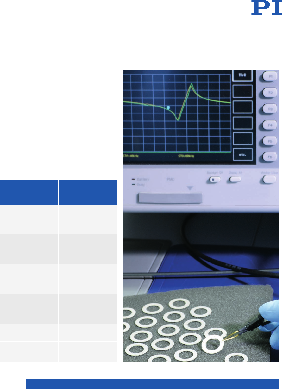
Figure 7 illustrates a typical impedance cur-
ve. The series and parallel resonances, fs and
fp, are used to determine the piezoelectric
parameters. These correspond to a good ap-
proximation to the impedance minimum fm
and maximum fn.
Oscillation States of Piezoelectric
Components
Oscillation states or modes and the de-
formation are decided by the geometry of the
element, mechano-elastic properties and
the orientations of the electric field and the
polarization. Coefficients see p. 10, speci-
fic values see p. 18. dimensions see p. 27.
The equations are used to calculate approx-
imation values.
Shape Oscillations Electrically Mechanically
induced induced
Type Mechanical Series resonance displacement voltage
deformation frequency (small signal) (small signal)
∆OD = U
d31OD
TH
∆L = U
d31L
TH
∆TH = d33U
∆L = U
d31L
TH
∆TH = d33U
∆L = d33U
∆L = d15U
U = – F3
4g33TH
πOD2
U = – F3
g33L
W TH
U = – F3
g15 TH
L W
U = – F1
g31
W
14
WWW.PICERAMIC.COM
Material Properties and Classification
PI Ceramic provides a wide selection of
piezoelectric ceramic materials based on
modified Lead Zirconate Titanate (PZT) and
Barium Titanate. The material properties
are classified according to the EN 50324
European Standard.
In addition to the standard types described
here in detail, a large number of modifica-
tions are available which have been adapted
to a variety of applications.
Internationally, the convention is to divide
piezo ceramics into two groups. The terms
“soft“ and “hard“ PZT ceramics refer to
the mobility of the dipoles or domains and
hence also to the polarization and depolar-
ization behavior.
“Soft“ Piezo Ceramics
Characteristic features are a comparably
high domain mobility and resulting “soft
ferroelectric“ behavior, i.e. it is relatively
easy to polarize. The advantages of the
“soft“ PZT materials are their large piezo-
electric charge coefficient, moderate per-
mittivities and high coupling factors.
Important fields of application for “soft“
piezo ceramics are actuators for micro-
positioning and nanopositioning, sensors
such as conventional vibration pickups,
ultrasonic transmitters and receivers for
flow or level measurement, for example,
object identification or monitoring as well
as electro-acoustic applications as sound
transducers and microphones, through
to their use as sound pickups on musical
instruments.
“Hard“ Piezo Ceramics
“Hard“ PZT materials can be subjected to
high electrical and mechanical stresses.
Their properties change only little under the-
se conditions and this makes them particu-
larly ideal for high-power applications. The
advantages of these PZT materials are the
moderate permittivity, large piezo electric
coupling factors, high qualities and very
good stability under high mechanical loads
and operating fields. Low dielectric losses
facilitate their continuous use in resonance
mode with only low intrinsic warming of
the component. These piezo elements
are used in ultrasonic cleaning (typically
kHz frequency range), for example, the
machining of materials (ultrasonic welding,
bonding, drilling, etc.), for ultra sonic pro-
cessors (e.g. to disperse liquid media), in
the medical field (ultrasonic tartar removal,
surgical instruments etc.) and also in sonar
technology.
15
PIEZO TECHNOLOGY
Piezoelectric ceramics, which nowadays
are based mainly on Lead Zirconate-Lead
Titanate compounds, are subject to an ex-
emption from the EU directive to reduce
hazardous substances (RoHS) and can there-
fore be used without hesitation. PI Ceramic is
nevertheless aiming to provide high-per for-
mance lead-free piezoceramic materials and
thus provide materials with a guaranteed
future. PI Ceramic is currently inves tigating
technologies to reliably manufacture
lead-free ceramic components in series
pro duc tion.
First Steps Towards Industrial Use
with PIC700
The PIC700 material, which is currently in
laboratory production, is the first lead-free
piezo ceramic material being offered on
the market by PI Ceramic. PIC700 is based
on Bismuth Sodium Titanate (BNT) and
has very similar characteristics to Barium
Titanate materials. PIC700 is suitable for
ultrasonic transducers in the MHz range as
well as sonar and hydrophone applications.
Characteristics of the Lead-Free
Piezo Ceramic Material
The maximum operating temperature of
the BNT-based ceramic is around 200 °C.
The permittivity and piezoelectric coupling
factors of BNT components are lower than
those of conventional, PZT materials. Even
though PIC700 is suitable for a number of
applications, an across-the-board replace-
ment for PZT piezoelectric elements in
technical applications is not in sight at the
moment.
Lead-Free Materials
Lead-Free and with High Linearity
Piezoceramic actuators exhibit nonlinear
displacement behavior: The voltage applied
is thus not a repeatable measure for the
position reached. Sensors must therefore
be used in applications where the position
is relevant. The crystalline PIC050 material,
in contrast, has a linearity which is signi-
ficantly improved by a factor of 10 so that a
position sensor is not necessary.
PIC050 is used for actuators and nanoposi-
tioning systems with the tradename Picoac-
tuator®. They have the high stiffness and
dynamics of actuators made of PZT material
but their displacement is limited: Travel of
up to +/-3 μm results with a maximum pro-
file of 20 mm.
Picoactuator® in Nanopositioning
In precision positioning technology, Physik
Instrumente (PI) uses these actuators precis-
e
ly where this small displacement with high
dynamics and accuracy is required. The
high linearity means that they can operate
without position control which otherwi-
se sets an upper limit for the dynamics of
the system as a result of the limited control
bandwidth.
Since it is used in positioning systems
the PIC050 material is only supplied as a
translational or shear actuator in predefi-
ned shapes. The standard dimensions are
similar to those of the PICA shear actuators
(see www.piceramic.com).
Crystalline Piezo Material for Actuators
The PIC050 crystal forms translucent layers in the Picoactuator®.
High-dynamics nanopositioning
system with Picoactuator®
technology.
Typical dimensions of cur-
rent PIC 700 components
are diameters of 10 mm and
thicknesses of 0.5 mm.

16
WWW.PICERAMIC.COM
Material Properties and Classification
Material
designation
General description of the material properties
“Soft“-PZT
Classification in accor-
dance with EN 50324-1
ML-Standard
DOD-STD-1376A
PIC151 Material: Modified Lead Zirconate-Lead Titanate
Characteristics: High permittivity, large coupling factor,
high piezoelectric charge coefficient
Suitable for: Actuators, low-power ultrasonic transducers,
low-frequency sound transducers. Standard material for
actuators of the PICA series: PICA Stack, PICA Thru
600 II
PIC255 Material: Modified Lead Zirconate-Lead Titanate
Characteristics: Very high Curie temperature, high permittivity,
high coupling factor, high charge coefficient, low mechanical
quality factor, low temperature coefficient
Suitable for: Actuator applications for dynamic operating
conditions and high ambient temperatures (PICA Power series),
low-power ultrasonic transducers, non-resonant broadband
systems, force and acoustic pickups, DuraAct patch transducers,
PICA Shear shear actuators
200 II
PIC155 Material: Modified Lead Zirconate-Lead Titanate
Characteristics: Very high Curie temperature, low mechanical
quality factor, low permittivity, high sensitivity (g coefficients)
Suitable for: Applications which require a high g coefficient
(piezoelectric voltage coefficient), e.g. for microphones and
vibration pickups with preamplifier, vibration measurements
at low frequencies
200 II
PIC153 Material: Modified Lead Zirconate-Lead Titanate
Characteristics: extremely high values for permittivity, coupling
factor, high charge coefficient, Curie temperature around 185 °C
Suitable for: Hydrophones, transducers in medical diagnostics,
actuators
600 VI
PIC152 Material: Modified Lead Zirconate-Lead Titanate
Characteristics: Very high Curie temperature
Suitable for: Use at temperatures up to 250 °C
(briefly up to 300 °C).
200 II

17
PIEZO TECHNOLOGY
Material
designation
General description of the material properties
“Hard“-PZT
Classification in accor-
dance with EN 50324-1
ML-Standard
DOD-STD-1376A
PIC181 Material: Modified Lead Zirconate-Lead Titanate
Characteristics: Extremely high mechanical quality factor,
good temperature and time constancy of the dielectric and
elastic values
Suitable for: High-power acoustic applications, applications in
resonance mode
100 I
PIC184 Material: Modified Lead Zirconate-Lead Titanate
Characteristics: Large electromechanical coupling factor, moderate-
ly high quality factor, excellent mechanical and electrical stability
Suitable for: High-power ultrasound applications, hydroacoustics,
sonar technology
100 I
PIC144 Material: Modified lead zirconate titanate
Characteristics: Large electromechanical coupling factor, high
quality factor, excellent mechanical and electrical stability, high
compressive resistance
Suitable for: High-power ultrasound applications, hydroacoustics,
sonar technology
100 I
PIC241 Material: Modified Lead Zirconate-Lead Titanate
Characteristics: High mechanical quality factor, higher permittivity
than PIC181
Suitable for: High-power acoustic applications, piezomotor drives
100 I
PIC300 Material: Modified Lead Zirconate-Lead Titanate
Characteristics: Very high Curie temperature
Suitable for: Use at temperatures up to 250 °C
(briefly up to 300 °C).
100 I
Lead-Free Materials
PIC050 Material: Spezial crystalline material
Characteristics: Excellent stability, Curie temperature >500 °C
Suitable for: High-precision, hysteresis-free positioning in
open-loop operation, Picoactuator®
PIC700 Material: Modified Bismuth Sodium Titanate
Characteristics: Maximum operation temperature 200 °C,
low density, high coupling factor of the thickness mode
of vibration, low planar coupling factor
Suitable for: Ultrasonic transducers > 1MHz

18
WWW.PICERAMIC.COM
Soft PZT materials Hard PZT materials Lead-free
materials
Unit PIC151
PIC255/
PIC2521)
PIC155
PIC153
PIC152
PIC181
PIC1842)
PIC1442)
PIC241
PIC300
PIC110
PIC7002)
Physical and dielectric properties
Density ρg/cm37.80 7.80 7.80 7.60 7.70 7.80 7.75 7.95 7.80 7.80 5.50 5.6
Curie temperature Tc°C 250 350 345 185 340 330 295 320 270 370 150 2003)
Relative permittivity in the polarization direction
to polarity
ε33
Τ/ε0
ε11
Τ/ε0
2400
1980
1750
1650
1450
1400
4200 1350 1200
1500
1015
1250
1250
1500
1650
1550
1050
950
950 700
Dielectric loss factor tan δ10-3 20 20 20 30 15 3 5 4 5 3 15 30
Electromechanical properties
Coupling factor kp
kt
k31
k33
k15
0.62
0.53
0.38
0.69
0.62
0.47
0.35
0.69
0.66
0.62
0.48
0.35
0.69
0.62 0.48
0.58
0.56
0.46
0.32
0.66
0.63
0.55
0.44
0.30
0.62
0.65
0.60
0.48
0.30
0.66
0.50
0.46
0.32
0.64
0.63
0.48
0.43
0.25
0.46
0.32
0.30
0.42
0.18
0.15
0.40
Piezoelectric charge coefficient d31
d33
d15
10-12 C/N
-210
500
-180
400
550
-165
360
600
300
-120
265
475
-100
219
418
-110
265
-130
290
265
-80
155
155
-50
120
120
Piezoelectric voltage coefficient g31
g33
10-3 Vm/N
-11.5
22
-11.3
25
-12.9
27
16
25
-11.2
25
-11.1
24.4
-10.1
25
-9.8
21
-9.5
16
-11.9
Acousto-mechanical properties
Frequency coefficients Np
N1
N3
Nt
Hz·m
1950
1500
1750
1950
2000
1420
2000
1960
1500
1780
1990
1960
1960
2250
1920
2270
1640
2010
2110
2195
1590
1930
2035
2180
1590
2020
2190
1590
1550
2140
2350
1700
1700
2100
3150
2300
2500
Elastic compliance coefficient S11
E
S33
E10-12 m2/ N
15.0
19.0
16.1
20.7
15.6
19.7
11.8
14.2
12.7
14.0
12.4
15.5
12.6
14.3
11.1
11.8
Elastic stiffness coefficient C33
D1010 N/m210.0 11.1 16.6 14.8 15.2 13.8 16.4
Mechanical quality factor Qm100 80 80 50 100 2000 400 1000 400 1400 250
Temperature stability
Temperature coefficient of εΤ
33
(in the range -20 °C to +125 °C)
TK ε33
10-3 / K
6
4
6
5
2
3
5
2
Time stability (relative change of the parameter per decade of time in %)
Relative permittivity
Coupling factor
Cε
CK
-1.0
-1.0
-2.0
-2.0
-4.0
-2.0
-5.0
-8.0
SPECIFIC PARAMETERS OF THE STANDARD MATERIALS
Material Data

19
PIEZO TECHNOLOGY
Recommended operating temperature:
50 % of Curie temperature.
1) Material for the Multilayer tape
technology.
2) Preliminary data, subject to change
3) Maximum operating temperature
The following values are valid approxima-
tions for all PZT materials from
PI Ceramic:
Specific heat capacity:
WK = approx. 350 J kg-1 K-1
Specific thermal conductivity :
WL = approx. 1.1 W m-1 K-1
Poisson‘s ratio (lateral contraction):
σ = approx. 0.34
Coefficient of thermal expansion:
α3 = approx. -4 to -6 × 10⁻⁶ K-1
(in the polarization direction, shorted)
α1 = approx. 4 to 8 × 10⁻⁶ K-1
(perpendicular to the polarization direction,
shorted)
Static compressive strength:
> 600 MPa
The data was determined using test
pieces with the geometric dimensions laid
down in EN 50324-2 standard and are typical
values.
All data provided was determined 24 h to
48 h after the time of polarization at an am-
bient temperature of 23 ±2 °C.
A complete coefficient matrix of the individ-
ual materials is available on request. If you
have any questions about the interpretation
of the material characteristics please contact
PI Ceramic (info@piceramic.com).
Soft PZT materials Hard PZT materials Lead-free
materials
Unit PIC151 PIC255/
PIC2521)
PIC155 PIC153 PIC152 PIC181 PIC1842) PIC1442) PIC241 PIC300 PIC110 PIC7002)
Physical and dielectric properties
Density ρg/cm37.80 7.80 7.80 7.60 7.70 7.80 7.75 7.95 7.80 7.80 5.50 5.6
Curie temperature Tc°C 250 350 345 185 340 330 295 320 270 370 150 2003)
Relative permittivity in the polarization direction
to polarity
ε33
Τ/ε0
ε11
Τ/ε0
2400
1980
1750
1650
1450
1400
4200 1350 1200
1500
1015
1250
1250
1500
1650
1550
1050
950
950 700
Dielectric loss factor tan δ10-3 20 20 20 30 15 3 5 4 5 3 15 30
Electromechanical properties
Coupling factor kp
kt
k31
k33
k15
0.62
0.53
0.38
0.69
0.62
0.47
0.35
0.69
0.66
0.62
0.48
0.35
0.69
0.62 0.48
0.58
0.56
0.46
0.32
0.66
0.63
0.55
0.44
0.30
0.62
0.65
0.60
0.48
0.30
0.66
0.50
0.46
0.32
0.64
0.63
0.48
0.43
0.25
0.46
0.32
0.30
0.42
0.18
0.15
0.40
Piezoelectric charge coefficient d31
d33
d15
10-12 C/N
-210
500
-180
400
550
-165
360 600 300
-120
265
475
-100
219
418
-110
265
-130
290
265
-80
155
155
-50
120 120
Piezoelectric voltage coefficient g31
g33
10-3 Vm/N
-11.5
22
-11.3
25
-12.9
27 16 25
-11.2
25
-11.1
24.4
-10.1
25
-9.8
21
-9.5
16 -11.9
Acousto-mechanical properties
Frequency coefficients Np
N1
N3
Nt
Hz·m
1950
1500
1750
1950
2000
1420
2000
1960
1500
1780
1990
1960
1960
2250
1920
2270
1640
2010
2110
2195
1590
1930
2035
2180
1590
2020
2190
1590
1550
2140
2350
1700
1700
2100
3150
2300
2500
Elastic compliance coefficient S11
E
S33
E10-12 m2/ N
15.0
19.0
16.1
20.7
15.6
19.7
11.8
14.2
12.7
14.0
12.4
15.5
12.6
14.3
11.1
11.8
Elastic stiffness coefficient C33
D1010 N/m210.0 11.1 16.6 14.8 15.2 13.8 16.4
Mechanical quality factor Qm100 80 80 50 100 2000 400 1000 400 1400 250
Temperature stability
Temperature coefficient of εΤ
33
(in the range -20 °C to +125 °C) TK ε33 10-3 / K 6465 2 3 5 2
Time stability (relative change of the parameter per decade of time in %)
Relative permittivity
Coupling factor
Cε
CK
-1.0
-1.0
-2.0
-2.0
-4.0
-2.0
-5.0
-8.0
20
WWW.PICERAMIC.COM
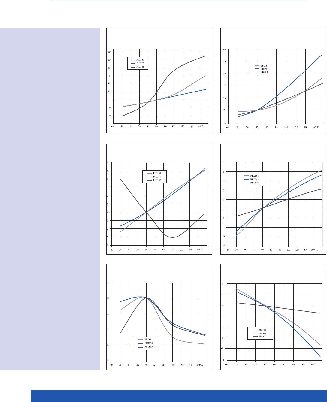
Temperature Dependence of the Coefficients
∆ C/C (%) ∆ C/C (%)
∆ k31 / k31 (%)
∆ fs/ fs (%)
Temperature curve of the
capacitance C
Materials: PIC151,
PIC255 and PIC155
Materials: PIC181,
PIC241 and PIC300
Temperature curve of the
resonant frequency of the
transverse oscillation fs
Materials: PIC151,
PIC255 and PIC155
Materials: PIC181,
PIC241 and PIC300
Temperature curve of the
coupling factor of the
transverse oscillation k31
Materials: PIC151,
PIC255 and PIC155
Materials: PIC181,
PIC241 and PIC300
∆ fs/ fs (%)
∆ k31 / k31 (%)
21
PIEZO TECHNOLOGY
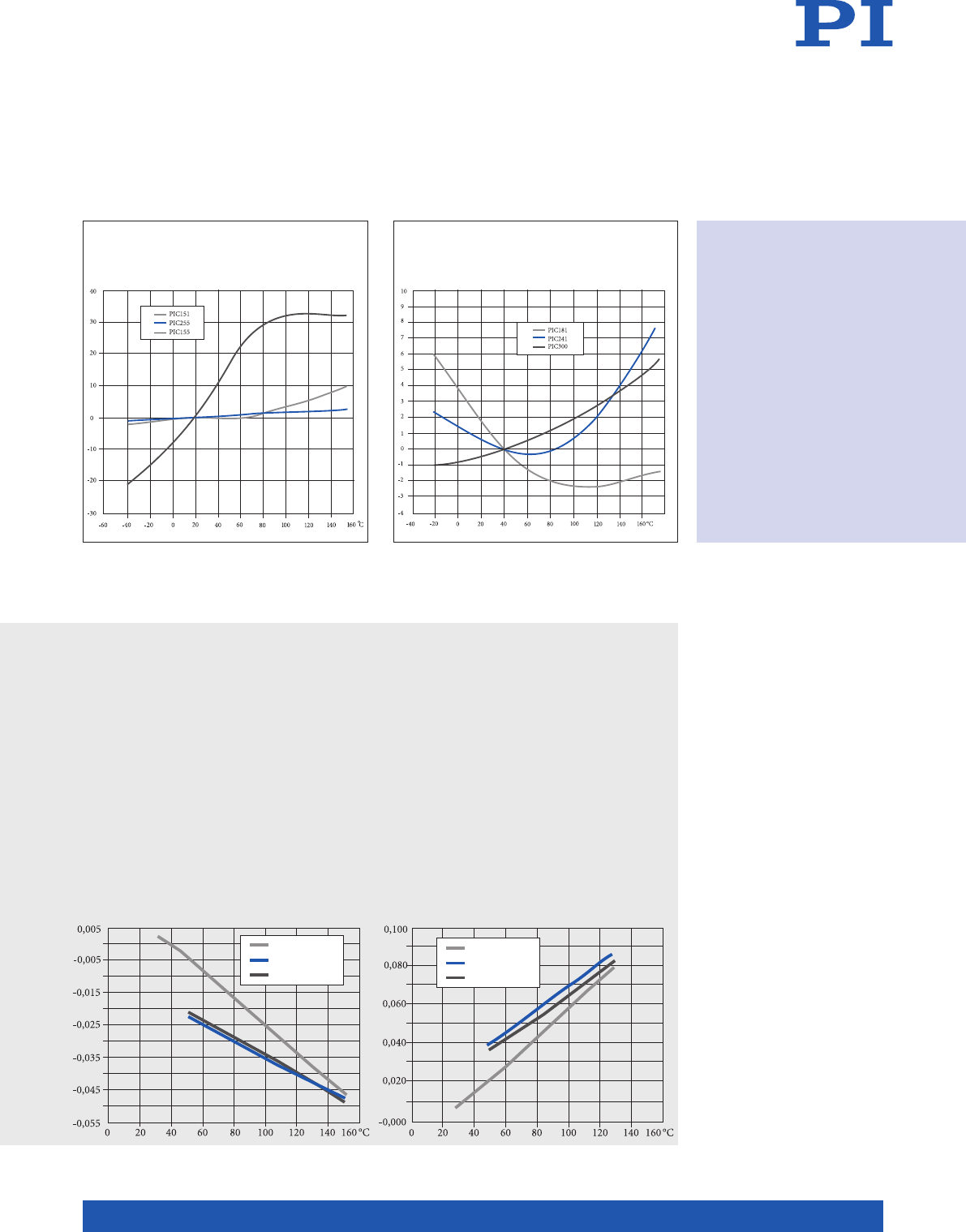
∆ d31 / d31 (%)
∆ d31 / d31 (%)
∆ L/L (%)
Thermal strain in the polarization direction Thermal strain perpendicular to the polarization
direction ∆ L/L (%)
1. Heating
Cooling
2. Heating
1. Heating
Cooling
2. Heating
1. Heating
Cooling
2. Heating
1. Heating
Cooling
2. Heating
Specific Characteristics
Thermal properties using the example of
the PZT ceramic PIC255
! The thermal strain exhibits different
behavior in the polarization direction and
perpendicular to it.
! The preferred orientation of the domains
in a polarized PZT body leads to an
anisotropy. This is the cause of the varying
thermal expansion behavior.
! Non-polarized piezoceramic elements are
isotropic. The coefficient of expansion is
approximately linear with a TK of approx
2 · 10-6 / K.
! The effect of successive temperature
changes must be heeded particularly in
the application. Large changes in the cur-
ve can occur particularly in the first tem-
perature cycle.
! Depending on the material, it is possib-
le that the curves deviate strongly from
those illustrated.
Temperature curve of
the piezoelectric charge
coefficient d31
Materials: PIC151,
PIC255 and PIC155
Materials: PIC181,
PIC241 and PIC300

22
WWW.PICERAMIC.COM
Piezo Components Made by Pressing
Technology
Piezoceramic bulk elements are manufac-
tured from spray-dried granular material
by mechanical hydraulic presses. The com-
pacts are either manufactured true to size,
taking into account the sintering contraction,
or with machining excesses which are then
reworked to achieve the required precision.
The sintered ceramic material is hard and
can be sawn and machined, if required.
Screen printing is used to metallize the pie-
zo elements and sputtering processes (PVD)
are employed for thin metallizing layers. The
sintered elements are then polarized.
Stack Design for Actuators
Piezo actuators are constructed by stacking
several piezoceramic bulk elements and
intermediate metal foils. Afterwards an ou-
ter insulation layer made of polymer mate-
rial is applied.
Final inspection
Manufacture of Piezo Components
Using Pressing Technology
Assembling and joining technology for
actuators, sound transducers, transducers
Polarization
Application of electrodes: Screen
printing, PVD processes, e.g. sputtering
Lapping, grinding, surface grinding,
diamond cutting
Thermal processing
Sintering at up to 1300 °C
Pressing and shaping
Granulation, spray drying
Milling
Pre-sintering (calcination)
Mixing and grinding
of the raw materials
Piezoceramic disks
with center hole
EFFICIENT PROCESSES FOR SMALL, MEDIUM-SIZED AND LARGE PRODUCTION RUNS
Manufacturing Technology

23
PIEZO TECHNOLOGY
Film Technology for Thin Ceramics
Components
Thin ceramic layers are produced by tape
casting. This process can achieve minimal
individual component thicknesses of only
50 μm.
The electrodes are then applied with special
screen printing or PVD processes.
Multilayer Piezo Actuators: PICMA®
Multilayer co-firing technology is an espe -
cially innovative manufacturing process.
The first step is to cast tapes of piezocera-
mic materials which are then provided with
electrodes while still in the green state. The
component is then laminated from individ-
ual layers. In the following electrodes and
ceramic are sintered together in a single
processing step.
The patented PICMA® design comprises an
additional ceramic insulation layer which
protects the inner electrodes from environ-
mental effects. Any further coatings made of
polymer material, for example, are therefore
not required. This means that PICMA® piezo
actuators remain stable even when subject
to high dynamic load. They achieve a higher
reliability and a lifetime which is ten times
longer than conventional multilayer piezo
actuators with a polymer insulation.
After the mechanical post-processing is com-
plete, the multilayer actuators are provided
with contact electrodes and are polarized.
PICMA® actuators with patented,
meander-shaped external electrodes
for up to 20 A charging current
Co-firing Process / Multilayer Technology / Piezo
Components inCeramics Tape Technology
Final inspection
Polarization
Application of contact electrodes,
termination
Grinding
Thermal processing
Binder burn out and sintering
at up to 1100 °C
Isostatic pressing
Laminating
Application of electrodes
by screen printing
Tape casting
Slurry preparation
Fine grinding of the raw materials
24
WWW.PICERAMIC.COM
Shaping of Compacts
Components such as disks or plates can be
manufactured at low cost with a minimum
thickness from as low as 0.2 mm. Inboard
automatic cutoff saws produce such pieces in
large numbers.
Modern CNC technology means the sintered
ceramic elements can be machined with the
highest precision. Holes with diameters of
down to 0.3 mm can be produced. Almost
any contours can be shaped with accuracies
to one tenth of a millimeter. Surfaces can be
structured and the components can be milled
to give a three-dimensional fit.
Ultrasonic machining processes are used
to manufacture thin-walled tubes with wall
thicknesses of 0.5 mm.
Robot-Assisted Series Production
Automated assembly and production lines
use fast pick-and-place devices and comput-
er-controlled soldering processes, for ex-
ample. An annual production run of several
million piezoelectric components and more
is thus no problem.
All Possible Shapes Even with
Full-Ceramic Encapsulation
PI Ceramic can manufacture almost any
shape of PICMA® multilayer piezo actua-
tor using the latest production technology.
Hereby, all surfaces are encapsulated with
ceramic insulation.
We can manufacture not only various ba-
sic shapes, e.g. round or triangular cross-
sections, but also insulated center holes on
benders, chips or stack actuators, making it
easier to integrate them.
Special milling machines work the sensitive
ceramic films in the green state, i.e. befo-
re sintering. The individual layers are then
equipped with electrodes and laminated.
The co-firing process is used to sinter the
ceramic and the internal electrodes together,
the same process as with PICMA® standard
actuators.
Flexibility in Shape and Design
Centerless, cylindrical grinding of piezoceramic rods
25
PIEZO TECHNOLOGY
The internal electrodes and the ceramic of
PICMA® multilayer actuators are sintered
together (co-firing technology) to create a
monolithic piezoceramic block. This pro-
cess creates an encapsulating ceramic lay-
er which provides protection from humi-
dity and from failure caused by increased
leakage current. PICMA® actuators are there-
fore far superior to conventional, polymer-
insulated multilayer piezo actuators in terms
of reliability and lifetime. The monolithic
ceramic design also gives rise to a high
resonance frequency, making the actuators
ideal for high-dynamic operation.
Large Temperature Range – Optimum
UHV Compatibility – Minimal Outgassing
– Neutral in Magnetic Fields
The particularly high Curie temperature
of 320 °C gives PICMA® actuators a usa-
ble temperature range of up to 150 °C, far
beyond the 80 °C limit of conventional mul-
tilayer actuators. This and the exclusive use
of inorganic materials provide the optimum
conditions for use in ultra-high vacuums: No
outgassing and high bake-out temperatures.
PICMA® piezo actuators even operate in the
cryogenic temperature range, albeit at re -
duced travel. Every actuator is constructed
exclusively of non-ferromagnetic materials,
giving them extremely low residual magne-
tism of the order of a few nanotesla.
Low Operating Voltage
In contrast to most commercially available
multilayer piezo actuators, PICMA® actu-
ators achieve their nominal displacement
at operating voltages far below 150 V. This
characteristic is achieved by using a parti c-
ularly fine-grained ceramic material which
means the internal layers can be thin.
The PICMA® actuators are at least partially
protected by the following patents:
German Patent No. 10021919
German Patent No. 10234787
German Patent No. 10348836
German Patent No. 102005015405
German Patent No. 102007011652
US Patent No. 7,449,077
PICMA® Multilayer Actuators with Long Lifetime
Automatic soldering machine with PICMA® actuators
26
WWW.PICERAMIC.COM
Thick-Film Electrodes
Screen printing is a standard procedure to ap-
ply the metal electrodes to the piezoce-ram ic
elements. Typical film thicknesses here are
around 10 μm. Various silver pastes are used
in this process. After screen print ing these
pastes are baked on at tempera-tures above
800 °C.
Thin-Film Electrodes
Thin-film electrodes are applied to the
ceramic using modern PVD processes
(sputtering). The typical thickness of the
metallization is in the range of 1 μm. Shear
elements must be metallized in the polar-
ized state and are generally equipped with
thin-film electrodes.
PI Ceramic has high-throughput sputtering
facilities which can apply electrodes made of
metal alloys, preferably CuNi alloys and no-
ble metals such as gold and silver.
Soldering Methods
Ready-made piezo components with
connecting wires are manufactured by
specially trained staff using hand solder-
ing processes. We have the latest automatic
soldering machines at our disposal to solder
on miniaturized components and for larger
production runs. Soldered joints which must
be extremely reliable undergo special visu-
al inspections. The optical techniques used
for this purpose range from the stereomi-
cro-scope through to camera inspection sys-
tems.
Mounting and Assembling Technology
The joining of products, e. g. with adhesives,
is carried out in the batch production using au-
tomated equipment which executes the nec-
essary temperature-time-regime (e.g. curing
of epoxy adhesives) and hence guarantees
uniform quality. The choice of adhesive and
the curing regime are optimized for every
product, taking into consideration the mate-
rial properties and the intended operational
conditions. Specifically devel-oped dosing
and positioning systems are used for com-
plex special designs. The piezoceramic stack
actuators of the PICA series, high-voltage
bender-type actuators and ultrasonic trans-
ducers are constructed in jointing processes
and have proved successful many times over
in the semi-conductor industry and in medical
engineering thanks to their high reliability.
Fully loaded sputtering equipment
THE COMPLETE PROCESS IS IN-HOUSE
Metallization and Assembling Technology
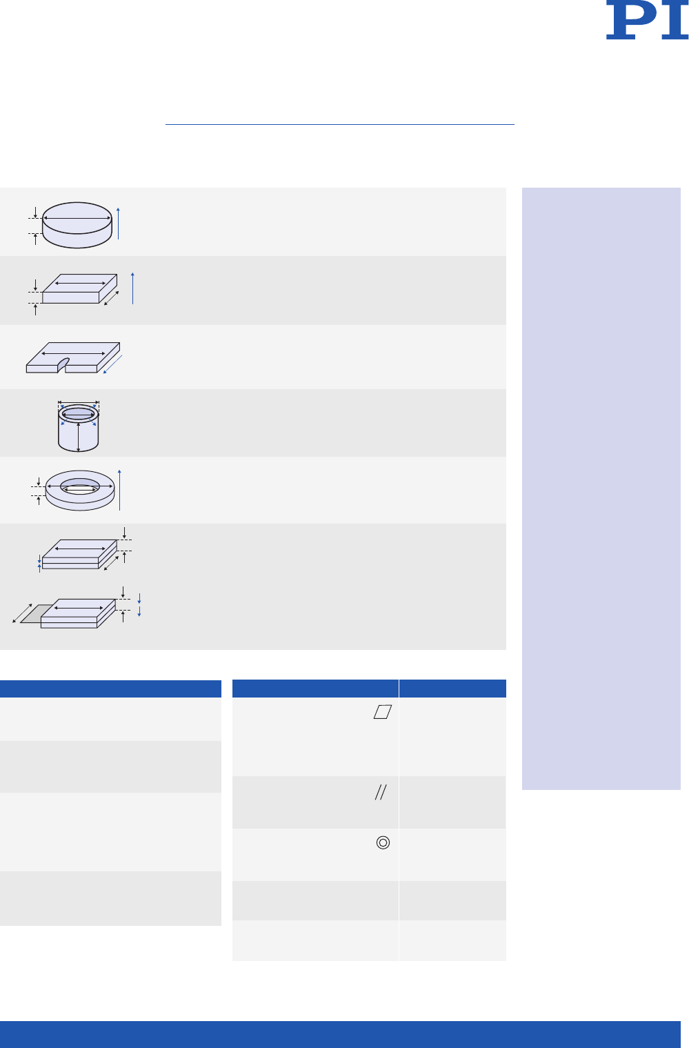
27
PIEZO TECHNOLOGY
! P indicates the
poling direction.
! The dimensions are
mutually dependent
and cannot be
chosen arbitrarily.
! The minimum
dimensions are
determined by
physical and
technological limits.
The thickness or
wall thickness, for
example, is limited
by the mechanical
strength of the
ceramic during
machining.
! Maximum thickness
for polarization:
30 mm
Labeling of the polarity
The surface of the
electrode which is at
the positive potential
during polarization is
marked with a dot or
a cross. Alternatively
and particularly for
thin-film electrodes
the direction of
polarization is marked
by coloring the
electrode material:
A reddish color
indicates the electrode
which was at the
positive potential
during the polarization.
Standard tolerances
Dimensions, as fired
± 0.3 mm resp. ± 3 %
Length L, width W (dimensions; tolerance)
< 15 mm; ± 0.15 mm < 40 mm; ± 0.25 mm
< 20 mm; ± 0.20 mm < 80 mm; ± 0.30 mm
Outer diameter OD,
inner diameter ID
(dimensions; tolerance)
< 15 mm; ± 0.15 mm < 40 mm; ± 0.25 mm
< 20 mm; ± 0.20 mm < 80 mm; ± 0.30 mm
Thickness TH (dimensions; tolerance)
< 10 mm; ± 0.05 mm < 40 mm; ± 0.15 mm
< 20 mm; ± 0.10 mm < 80 mm; ± 0.20 mm
Disk / Outer diameter OD: 2 to 80 mm
rod / cylinder Thickness TH: 0.15 to 30 mm
Plate / block Length L: 1 to 80 mm,
Width W: 1 to 60 mm,
Thickness TH: 0.1 to 30 mm
Shear plate Length L: max. 75 mm,
Width W: max. 25 mm,
Thickness TH: 0.2 to 10 mm
Tube Outer diameter OD: 2 to 80 mm,
Inner diameter ID: 0.8 to 74 mm,
Length L: max. 30 mm
Ring Outer diameter OD: 2 to 80 mm,
Inner diameter ID: 0.8 to 74 mm,
Thickness TH: max. 70 mm
Bender elements Length L: 3 to 50 mm,
constructed in Width W: 1 to 25 mm,
series / parallel Thickness TH: 0.4 to 1.5 mm
Round bender elements on request.
Preferred dimensions:
Diameter: 5 to 50 mm,
Thickness: 0.3 to 2 mm
L
+
o
∆L
Polarisation
axis
C1
L1
C0
Impendanz Z
Frequenz f
fmfn
∆ L
V0
(2)
+
–
+
–
+
–
+
–
+
–
+
–
+
–
+
–
+
–
+
–
+
–
+
–
(3)
+
–
+
–
+
–
+
–
+
–
+
–
+
–
+
–
+
–
+
–
+
–
+
–
(1)
+
–
+
–
+
–
+
–
+
–
+
–
+
–
+
–
U
+
–
P C/m2
E kV/cm
Ps
Ec
-Ec
Pr
-Pr
-Ps
+
–
+
–
+
–
+
–
+
–
+
–
+
–
+
–
+
–
+
–
3
1(r)
3
3(r)
Radialschwingung
Dickenschwingung
Radialschwingung
Dickenschwingung
Längsschwingung
Radialschwingung
Dickenschwingung
OD
ID
TH P
(1)
(2)
O2
Pb
Ti, Zr
Längsschwingung
Dickenschwingung
3
1(r)
1
3
2
TH
5
6
3
1
2
3
2
TH
5
6
1
P
TH
W
LP
TH
L
W
P
L
W
TH
P
TH
W
L
L
P
L
P
D
P
TH
OD
P
L
OD
ID
OD
TH TH
OD
(Z)
3
2(Y)
(X)1
6
5
4
P
(Z)
3
2(Y)
(X)1
6
5
4
P
P
WTH
L
R1
Dimension Tolerance
Deviation from flatness < 0.02 mm
(slight bending of
thin disks or plates
is not taken
into account)
Deviation < 0.02 mm
from
parallelism
Deviation <_ 0.4 mm
from
concentricity
Frequency ± 5 % (< 2 MHz)
tolerance ± 10 % (>
= 2 MHz)
Tolerance of ± 20 %
electric capacitance
L
+
o
∆L
Polarisation
axis
C1
L1
C0
Impendanz Z
Frequenz f
fmfn
∆ L
V0
(2)
+
–
+
–
+
–
+
–
+
–
+
–
+
–
+
–
+
–
+
–
+
–
+
–
(3)
+
–
+
–
+
–
+
–
+
–
+
–
+
–
+
–
+
–
+
–
+
–
+
–
(1)
+
–
+
–
+
–
+
–
+
–
+
–
+
–
+
–
U
+
–
P C/m2
E kV/cm
Ps
Ec
-Ec
Pr
-Pr
-Ps
+
–
+
–
+
–
+
–
+
–
+
–
+
–
+
–
+
–
+
–
3
1(r)
3
3(r)
Radialschwingung
Dickenschwingung
Radialschwingung
Dickenschwingung
Längsschwingung
Radialschwingung
Dickenschwingung
OD
ID
TH P
(1)
(2)
O2
Pb
Ti, Zr
Längsschwingung
Dickenschwingung
3
1(r)
1
3
2
TH
5
6
3
1
2
3
2
TH
5
6
1
P
TH
W
L
P
TH
L
W
P
L
W
TH
P
TH
W
L
L
P
L
P
D
P
TH
OD
P
L
OD
ID
OD
TH TH
OD
(Z)
3
2(Y)
(X)1
6
5
4
P
(Z)
3
2(Y)
(X)1
6
5
4
P
P
WTH
L
R1
L
+
o
∆L
Polarisation
axis
C1
L1
C0
Impendanz Z
Frequenz f
fmfn
∆ L
V0
(2)
+
–
+
–
+
–
+
–
+
–
+
–
+
–
+
–
+
–
+
–
+
–
+
–
(3)
+
–
+
–
+
–
+
–
+
–
+
–
+
–
+
–
+
–
+
–
+
–
+
–
(1)
+
–
+
–
+
–
+
–
+
–
+
–
+
–
+
–
U
+
–
P C/m2
E kV/cm
Ps
Ec
-Ec
Pr
-Pr
-Ps
+
–
+
–
+
–
+
–
+
–
+
–
+
–
+
–
+
–
+
–
3
1(r)
3
3(r)
Radialschwingung
Dickenschwingung
Radialschwingung
Dickenschwingung
Längsschwingung
Radialschwingung
Dickenschwingung
OD
ID
TH P
(1)
(2)
O2
Pb
Ti, Zr
Längsschwingung
Dickenschwingung
3
1(r)
1
3
2
TH
5
6
3
1
2
3
2
TH
5
6
1
P
TH
W
LP
TH
L
W
P
L
W
TH
P
TH
W
L
L
P
L
P
D
P
TH
OD
P
L
OD
ID
OD
TH TH
OD
(Z)
3
2(Y)
(X)1
6
5
4
P
(Z)
3
2(Y)
(X)1
6
5
4
P
P
WTH
L
R1
L
+
o
∆L
Polarisation
axis
C1
L1
C0
Impendanz Z
Frequenz f
fmfn
∆ L
V0
(2)
+
–
+
–
+
–
+
–
+
–
+
–
+
–
+
–
+
–
+
–
+
–
+
–
(3)
+
–
+
–
+
–
+
–
+
–
+
–
+
–
+
–
+
–
+
–
+
–
+
–
(1)
+
–
+
–
+
–
+
–
+
–
+
–
+
–
+
–
U
+
–
P C/m2
E kV/cm
Ps
Ec
-Ec
Pr
-Pr
-Ps
+
–
+
–
+
–
+
–
+
–
+
–
+
–
+
–
+
–
+
–
3
1(r)
3
3(r)
Radialschwingung
Dickenschwingung
Radialschwingung
Dickenschwingung
Längsschwingung
Radialschwingung
Dickenschwingung
OD
ID
TH P
(1)
(2)
O2
Pb
Ti, Zr
Längsschwingung
Dickenschwingung
3
1(r)
1
3
2
TH
5
6
3
1
2
3
2
TH
5
6
1
P
TH
W
LP
TH
L
W
P
L
W
TH
P
TH
W
L
L
P
L
P
D
P
TH
OD
P
L
OD
ID
OD
TH TH
OD
(Z)
3
2(Y)
(X)1
6
5
4
P
(Z)
3
2(Y)
(X)1
6
5
4
P
P
WTH
L
R1
DIMENSIONS
Piezoceramic Components

28
WWW.PICERAMIC.COM
Components with standard dimensions can
be supplied at very short notice on the basis
of semi-finished materials in stock. Extreme
values cannot be combined. Geometries
which exceed the standard dimensions are
available on request.
Disk / rod / cylinder Disk / rod
with defined resonant frequency
Plate / block
Electrodes: Fired silver
(thick film) or PVD
(thin film, different
materials: e. g. CuNi or
Au)
Points: Resonant
frequency > 1 MHz
Circles: Resonant
frequency < 1 MHz
Electrodes: Fired silver
(thick film) or PVD
(thin film, different
materials: e. g. CuNi or
Au)
Electrodes: Fired silver
(thick film) or CuNi or Au
(thin film)
Standard Dimensions
TH OD in mm
in mm
3 5 10 16 20 25 35 40 45 50
0.20 •••••
0.25 •••••
0.30 ••••••
0.40 •••••••
0.50 •••••••••
0.75 ••••••••••
1.00 ••••••••••
2.00 ••••••••••
3.00
••••••••••
4.00
••••••••••
5.00
••••••••••
10.00
••••••••••
20.00
••••••••••
TH OD in mm
in MHz
3 5 10 16 20 25 35 40 45 50
10
.00 •••••
5.00 ••••••
4.00 •••••••
3.00 ••••••••
2.00 ••••••••
1.00 ••••••••
0.75 oooooooo
0.50 ooooooo
0.40
oooooo
0.25
oooo
0.20
ooo
TH LxW in mm
2
in mm
4 x 4 5 x 5 10 x 10 15 x 15 20 x 20 25 x 20 25 x 25 50 x 30 50 x 50 75 x 25
0.20 •••••
0.25 •••••
0.30 •••••••
0.40 •••••••
0.50 •••••••••
0.75 ••••••••••
1.00 ••••••••••
2.00 ••••••••••
3.00
••••••••••
4.00
••••••••••
5.00
••••••••••
10.00
••••••••••
20.00
••••••••

29
PIEZO TECHNOLOGY
Rings
* Tolerances as fired,
s. table p. 27
Design
Design
Tubes
Design
Tubes with special electrodes
Design
Quartered outer
electrodes
Soldering instructions
for users
All our metallizations
can be soldered in
conformance with
RoHS. We recom-
mend the use of a
solder with the com-
position Sn 95.5. Ag
3.8. Cu 0.7. If the
piezoceramic element
is heated throughout
above the Curie
temperature, the
material is depolari-
zed, and there is thus
a loss of, or reduction
in, the piezoelectric
parameters.
This can be prevented
by adhering to the
following conditions
under all circum-
stances when solde-
ring:
! All soldered
contacts must be
point contacts.
! The soldering times
must be as short
as possible (≤ 3 sec).
! The specific
soldering
temperature must
not be exceeded.
Disk / rod
with defined resonant frequency
Wrap-around
contacts
OD in mm TH in mm Electrodes:
10 / 16 / 20 / 20 / 25 / 40 0.5 / 1.0 / 2.0 Fired silver
(thick film)
or PVD (thin film)
OD in mm ID in mm TH in mm Electrodes:
10 2.7 0.5/1.0/2.0 Fired silver
10* 4.3* 0.5/1.0/2.0 (thick film)
10* 5* 0.5/1.0/2.0 or CuNi
12.7 5.2* 0.5/1.0/2.0 (thin film)
25 16* 0.5/1.0/2.0
38 13* 5.0/6.0
50 19.7* 5.0/6.0/9.5
OD in mm ID in mm L in mm Electrodes:
76 60 50 Inside:
40 38 40 Fired silver
20 18 30 (thick film)
10 9 30 Outside:
10 8 30 Fired silver
6.35 5.35 30 (thick film)
3.2 2.2 30 or CuNi or Au
2.2 1.0 20 (thin film)
OD in mm ID in mm L in mm Electrodes:
20 18 30 Inside:
10 9 30 Fired silver
10 8 30 (thick film)
6.35 5.53 30 Outside:
3.2 2.2 30 Fired silver
2.2 1.0 30 (thick film)
or CuNi or Au
(thin film)
Disks with special electrodes (wrap-around contacts)
L
+
o
∆L
Polarisation
axis
C1
L1
C0
Impendanz Z
Frequenz f
fmfn
∆ L
V0
(2)
+
–
+
–
+
–
+
–
+
–
+
–
+
–
+
–
+
–
+
–
+
–
+
–
(3)
+
–
+
–
+
–
+
–
+
–
+
–
+
–
+
–
+
–
+
–
+
–
+
–
(1)
+
–
+
–
+
–
+
–
+
–
+
–
+
–
+
–
U
+
–
P C/m2
E kV/cm
Ps
Ec
-Ec
Pr
-Pr
-Ps
+
–
+
–
+
–
+
–
+
–
+
–
+
–
+
–
+
–
+
–
3
1(r)
3
3(r)
Radialschwingung
Dickenschwingung
Radialschwingung
Dickenschwingung
Längsschwingung
Radialschwingung
Dickenschwingung
OD
ID
TH P
(1)
(2)
O2
Pb
Ti, Zr
Längsschwingung
Dickenschwingung
3
1(r)
1
3
2
TH
5
6
3
1
2
3
2
TH
5
6
1
P
TH
W
LP
TH
L
W
P
L
W
TH
P
TH
W
L
L
P
L
P
D
P
TH
OD
P
L
OD
ID
OD
TH TH
OD
(Z)
3
2(Y)
(X)1
6
5
4
P
(Z)
3
2(Y)
(X)1
6
5
4
P
P
WTH
L
R1
L
+
o
∆L
Polarisation
axis
C1
L1
C0
Impendanz Z
Frequenz f
fmfn
∆ L
V0
(2)
+
–
+
–
+
–
+
–
+
–
+
–
+
–
+
–
+
–
+
–
+
–
+
–
(3)
+
–
+
–
+
–
+
–
+
–
+
–
+
–
+
–
+
–
+
–
+
–
+
–
(1)
+
–
+
–
+
–
+
–
+
–
+
–
+
–
+
–
U
+
–
P C/m2
E kV/cm
Ps
Ec
-Ec
Pr
-Pr
-Ps
+
–
+
–
+
–
+
–
+
–
+
–
+
–
+
–
+
–
+
–
3
1(r)
3
3(r)
Radialschwingung
Dickenschwingung
Radialschwingung
Dickenschwingung
Längsschwingung
Radialschwingung
Dickenschwingung
OD
ID
TH P
(1)
(2)
O2
Pb
Ti, Zr
Längsschwingung
Dickenschwingung
3
1(r)
1
3
2
TH
5
6
3
1
2
3
2
TH
5
6
1
P
TH
W
LP
TH
L
W
P
L
W
TH
P
TH
W
L
L
P
L
P
D
P
TH
OD
P
L
OD
ID
OD
TH TH
OD
(Z)
3
2(Y)
(X)1
6
5
4
P
(Z)
3
2(Y)
(X)1
6
5
4
P
P
WTH
L
R1
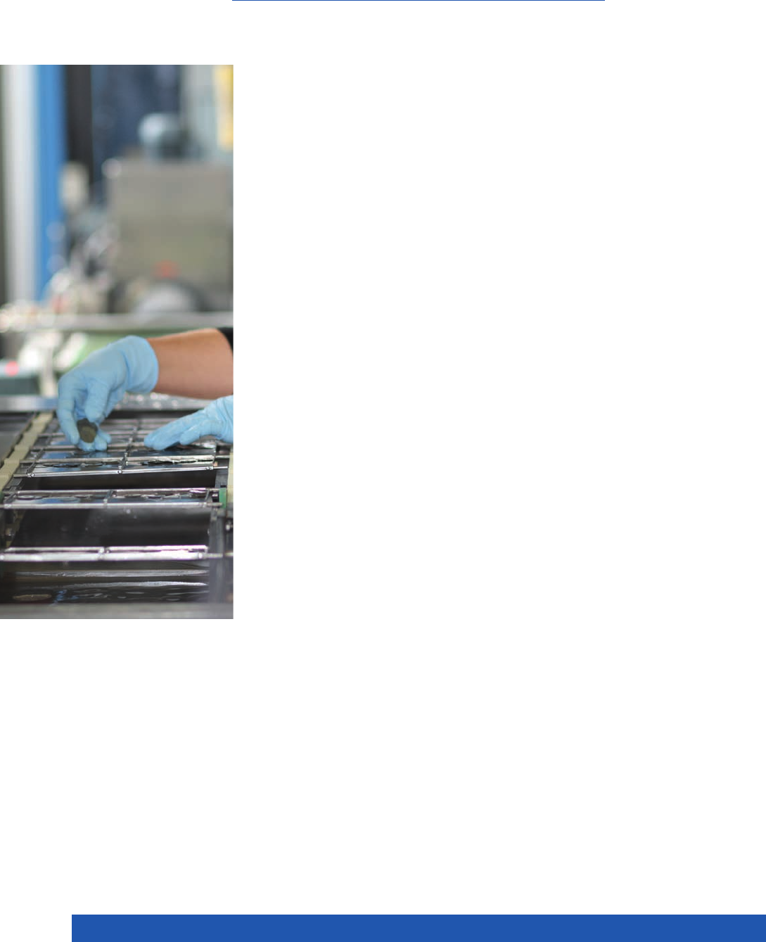
30
WWW.PICERAMIC.COM
Comprehensive quality management con-
trols all production process at PI Ceramic,
from the quality of the raw materials through
to the finished product. This ensures that
only released parts that meet the quality
speci fications go on for further processing
and delivery.
Electrical Testing
Small-Signal Measurements
The data for the piezoelectric and dielectric
properties such as frequencies, impedanc-
es, coupling factors, capacitances and loss
factors is determined in small-signal mea -
s urements.
Large-Signal Measurements
DC measurements with voltages of up
to 1200 V are carried out on actuators to de-
termine the strain, hysteresis and dielectric
strength in an automated routine test.
Geometric and Visual Testing Processes
For complex measurements, image pro-
cessing measurement devices and white-
light interferometers for topographical
exami nations are available.
Visual Limit Values
Ceramic components must conform to
certain visual specifications. PI Ceramic has
set its own criteria for the quality assess-
ment of the surface finishes, which follow
the former MIL-STD-1376. A large variety
of appli cations are taken into account, for
special requirements there are graduated
sorting categories. Visual peculiarities must
not negatively affect the functioning of the
component.
The finish criteria relate to:
! surface finish of the electrode
! pores in the ceramic
! chipping of the edges, scratches, etc.
Quality Level
All tests are carried out in accordance with
the DIN ISO 2859 standardized sampling
method. The AQL 1.0 level of testing ap-
plies for the electrical assessment, for ex-
ample. A special product specification can
be agreed for custom-engineered products.
This includes the relevant release records,
plots of the measured values or individual
measured values of certain test samples
through to the testing of each individual
piece, for example.
Measurement of Material Data
The data is determined using test pieces
with the geometric dimensions laid down
in accordance with the EN 50324-2 stan-
dard and are typical values (see p. 14 ff).
Con- formance to these typical parameters
is documented by continual testing of the
individual material batches before they are
released. The characteristics of the individ-
ual product can deviate from this and are
determined as a function of the geometry,
varia-tions in the manufacturing processes
and measuring or control conditions.
STANDARDIZED PROCEDURES PROVIDE CERTAINTY
Testing Procedures

31
PIEZO TECHNOLOGY
Ceramics in Different Levels of Integration
PI Ceramic integrates piezo ceramics into
the customer’s product. This includes both
the electrical contacting of the elements ac-
cording to customer requirements and the
mounting of components provided by the
customer, i. e. the gluing or the casting of
the piezoceramic elements. For the custom-
er, this means an accelerated manu facturing
process and shorter lead times.
Sensor Components – Transducers
PI Ceramic supplies complete sound trans-
ducers in large batches for a wide variety
of application fields. These include OEM as-
semblies for ultrasonic flow measurement
technology, level, force and acceleration
measurement.
Piezo Actuators
The simplest form for a piezo actuator is
a piezo disk or plate, from which stack
actuators with correspondingly higher
displacement can be constructed. As an
alternative, multilayer actuators are man-
ufactured in different lengths from piezo
films with layer thicknesses below 100 μm.
Shear actuators consist of stacks of shear
plates and are polarized such that they have
a displacement perpendicular to the field
applied. Bender actuators in different ba-
sic forms are constructed with two layers
(bimorph) by means of multilayer techno-
logy and thus provide a symmetric displace-
ment.
Piezo actuators can be equipped with
sensors to measure the displacement and
are then suitable for repeatable position-
ing with nanometer accuracy. Piezo actua-
tors are often integrated into a mechanical
system where lever amplification increases
the travel. Flexure guiding systems then
provide high stiffness and minimize the
lateral offset.
Piezo Motors
Piezo ceramics are the drive element for
piezomotors from Physik Instrumente (PI),
which make it possible to use the special
characteristics of the piezo actuators over
longer travel ranges as well.
PILine® piezo ultrasonic motors allow for
very dynamic placement motions and can
be manufactured with such a compact form
that they are already being used in many
new applications.
Piezo stepping drives provide the high
forces which piezo actuators generate over
several millimeters. The patented NEXLINE®
and NEXACT® drives from PI with their
complex construction from longitudinal,
shear and bender elements and the nec-
essary contacting are manufactured com-
pletely at PI Ceramic.
FROM THE CERAMIC TO THE COMPLETE SOLUTION
Integrated Components, Sub-Assemblies
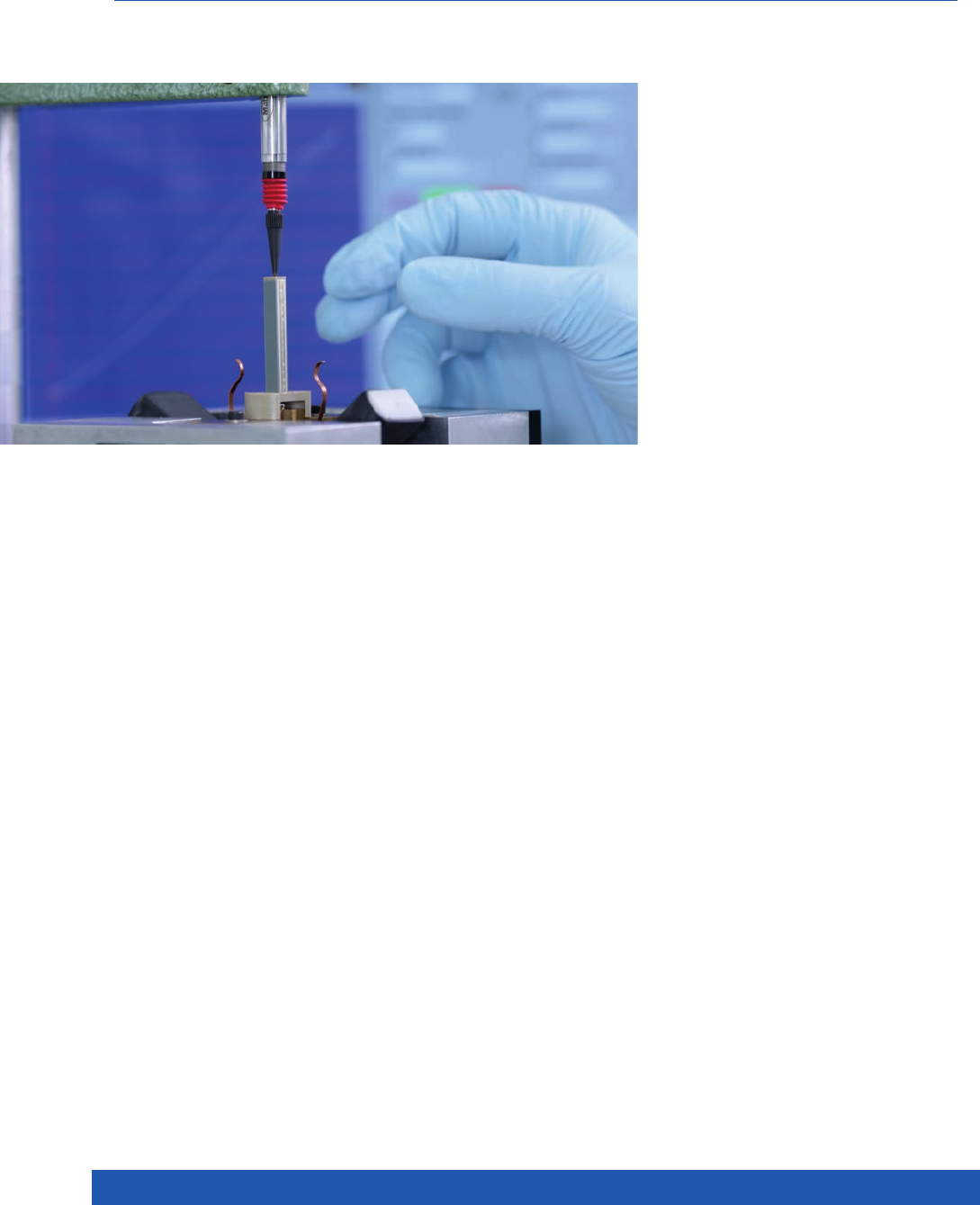
32
WWW.PICERAMIC.COM
Medical engineering, biotechnology, me-
chanical engineering or production techno-
logy through to semiconductor technology
– countless fields benefit from the piezo-
electric characteristics of the components.
Both the direct and the inverse piezoelectric
effect have industrial applications.
Direct Piezoelectric Effect
The piezo element converts mechanical
quantities such as pressure, strain or accel-
eration into a measureable electric voltage.
Mechano-Electrical Transducers
! Sensors for acceleration and pressure
! Vibration pickups, e.g. for the detection of
imbalances on rotating machine parts or
crash detectors in the automotive field
! Ignition elements
! Piezo keyboards
! Generators, e. g. self-supporting energy
sources (energy harvesting)
! Passive damping
Acousto-Electrical Transducers
! Sound and ultrasound receivers,
e.g. microphones, level and flow
rate measurements
! Noise analysis
! Acoustic Emission Spectroscopy
Inverse Piezoelectric Effect
The piezo element deforms when an electric
voltage is applied; mechanical motions or
oscillations are generated.
Electro-Mechanical Transducers
Actuators, such as translators, bender ele-
ments, piezo motors, for example:
! Micro- and nanopositioning.
! Laser Tuning
! Vibration damping
! Micropumps
! Pneumatic valves
Electro-Acoustic Transducers
! Signal generator (buzzer)
! High-voltage sources / transformers
! Delay lines
! High-powered ultrasonic generators:
Cleaning, welding, atomization, etc.
Ultrasonic signal processing uses both
effects and evaluates propagation times,
reflection and phase shift of ultrasonic wa-
ves in a frequency band from a few hertz
right up to several megahertz.
Applications are e. g.
! Level measurement
! Flow rate measurement
! Object recognition and monitoring
! Medical diagnostics
! High-resolution materials testing
! Sonar and echo sounders
! Adaptive structures
VERSATILE AND FLEXIBLE
Application Examples for Piezo Ceramic Products

33
PIEZO TECHNOLOGY
Increasing miniaturization places conti-
nuously higher demands on the components
used, and thus on the drives for microdosing
systems as well. Piezoelectric elements pro-
vide the solution here: They are reliable, fast
and precise in operation and can be shaped
to fit into the smallest installation space. At
the same time their energy consumption is
low, and they are small and low-cost. The
dosing quantities range from milliliter, mi-
croliter, nanoliter right down to the picoliter
range.
The fields of application for piezoelectric
pumps are in laboratory technology and
med ical engineering, biotechnology, chemi-
cal analysis and process engineering which
frequently require reliable dosing of minute
amounts of liquids and gases.
Micro-Diaphragm Pumps,
Microdosing Valves
The drive for the pump consists of a pie-
zo-electric actuator connected to a pump
diaphragm, usually made of metal or sili-
con. The deformation of the piezo element
changes the volume in the pump chamber,
the drive being separated from the medium
to be pumped by the diaphragm. Depen-
ding on the drop size and the diaphragm lift
thus required, and also the viscosity of the
medium, they can be driven directly with pie-
zo disks, piezo stack actuators or by means
of levered systems.
Their compact dimensions also make the-
se dosing devices suitable for lab-on-a-chip
applications.
Piezo drives are also used for opening and
closing valves. The range here is from a
simple piezo element or bender actuator for
a diaphragm valve, preloaded piezo stack ac-
tuators for large dynamics and force through
to piezo levers which carry out fine dosing
even at high backpressure.
In the automotive industry, fuel injection
systems driven by multilayer stack actuators
are also microdosing valves.
Peristaltic Pumps, Jet Dispensers
So-called peristaltic pumps are ideal in
cases where liquids or gases are to be
dosed accurately and also as evenly and
with as little pulsing as possible. The
external mechanical deformation of the
tube forces the medium to be transported
through this tube. The pumping direction is
determined by the control of the individual
actuators.
The drive element consists of flat piezo bend -
er elements, compact piezo chip actuators
or piezo stack actuators, depending on the
power and size requirements. Bender ac-
tuators are suitable mainly for applications
with low backpressure, e.g. for liquids with
low viscosity.
Piezo actuators are better able to cope with
higher backpressure and are suitable for
dosing substances with higher viscosity, but
require more space.
Piezoelectric Microdispensers,
Drop-on-Demand
Piezoelectric microdispensers consist of a
liquid-filled capillary which is shaped into
a nozzle and a surrounding piezo tube.
When a voltage is applied, the piezo tube
contracts and generates a pressure wave
in the capillary. This means that individual
drops are pinched off and accelerated to a
velocity of a few meters per second so that
they can travel over several centimeters.
The volume of the drop varies with the
properties of the medium transported, the
dimensions of the pump capillaries and the
control parameters of the piezo actuator.
Micro-channels etched into silicon can also
be used as nozzles.
Pumping and Dosing Techniques with Piezo Drives
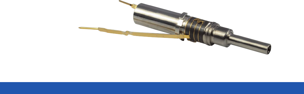
34
WWW.PICERAMIC.COM
The piezoelectric effect is used for a lar-
ge number of applications in the life sci-
ences: For example, for imaging in medical
diagnostics, in therapy for the treatment of
pain, for aerosol generation or the remo-
val of tartar from teeth, for scalpels in eye
surgery, for monitoring liquids, such as in
the detection of air bubbles in dialysis, or
also as a drive for dispensers and micro-
pumps.
If high power densities are required, as is
the case with ultrasonic tartar removal or for
surgical instruments, for example, “hard“
PZT materials are used.
Ultrasonic Instruments in Surgical and
Cosmetic Applications
Nowadays, instruments with ultrasonic
drives allow minimally invasive surgical
techniques in eye and oral surgery, for ex-
ample. Devices for liposuction are also of-
ten based on ultrasonic technology. Piezo
elements have long been used as ultrasonic
generators to remove mineral deposits on
human teeth.
The principle is always similar and works
just like ultrasonic material machining:
Piezoceramic composite systems made of
ring disks clamped together are integrated
in a sonotrode in the form of a medical in-
strument. This transmits vibration amplitu-
des in the μm range at operating frequen-
cies of around 40 kHz.
Ultrasound Imaging – Sonography
The big advantage of sonography is the
harmlessness of the sound waves, which is
why the method is widely used. The ultra-
sonic transmitter contains a piezo element,
which generates ultrasonic waves and also
detects them again. The ultrasonic trans-
mitter emits short, directional sound wave
pulses which are reflected and scattered by
the tissue layers to different degrees. By
measuring the propagation time and the
magnitude of the reflection an image of the
structure under investigation is produced.
Ultrasound Applications in Medical Engineering
Instruments for the removal of tartar with ultrasound,
OEM product. The piezo disks can be clearly seen.

35
PIEZO TECHNOLOGY
Ultrasound Therapy
This method involves irradiating the tissue
with ultrasonic waves by means of an ultra-
sonic transmitter. On the one hand, mechan-
ical, longitudinal waves generate vibrations
in the tissue, on the other, they convert part
of the ultrasonic energy into heat.
Typical working frequencies are in the ran-
ge 0.8 to over 3 MHz, both continuous wave
and pulsed wave ultrasonic techniques
being used in the application. The vibrati-
on amplitudes transmitted are in the range
around 1 μm.
Different effects are achieved depending
on the energy of the radiation. High-energy
shock waves are used to destroy kidney
stones, for example. Low-energy shock wa-
ves effect a type of micro-massage, and are
used for the treatment of bones and tissue
and in physiotherapy among other things.
In cosmetic applications ultrasonophoresis,
i.e. the introduction of drugs into the skin, is
becoming increasingly important.
Aerosol Production
Ultrasound makes it possible to nebulize
liquids without increasing the pressure or
the temperature, a fact which is of crucial
importance particularly for sensitive sub-
stances such medicines.
The process is similar to high-frequency
ultrasonic cleaning – a piezoceramic disk
fixed in the liquid container and oscillating
in resonance generates high-intensity ultra-
sonic waves. The drops of liquid are created
near the surface by capillary waves.
The diameter of the aerosol droplets is
determined by the frequency of the ultra-
sonic waves: The higher the frequency, the
smaller the droplets.
For direct atomization, where the piezo
element oscillating at high frequency is in
direct contact with the liquid, the piezo sur-
face is specially treated against aggressive
substances.
Flow Rate Measurement
In many areas the measurement of flow
rates is the basis for processes operating
in a controlled way. In modern building
services, for example, the consumption
of water, hot water or heating energy is
recorded and the supply as well as the
billing is thus controlled.
In industrial automation and especially in
the chemical industry, volume measurement
can replace the weighing of substance
quantities.
Not only the flow velocity, but also the
concentration of certain substances can be
detected.
The measurement of the propagation time
is based on the transmitting and receiving
of ultrasonic pulses on alternating sides
in the direction of flow and in the opposi-
te direction. Here, two piezo transducers
operating as both transmitter and receiver
are arranged in a sound section diagonally
to the direction of flow.
The Doppler effect is used to evaluate the
phase and frequency shift of the ultraso-
nic waves which are scattered or reflected
by particles of liquid. The frequency shift
between the emitted wave front and the
reflected wave front received by the same
piezo transducer is a measure of the flow
velocity.
Ultrasonic Sensors:
Piezo Elements in Metrology
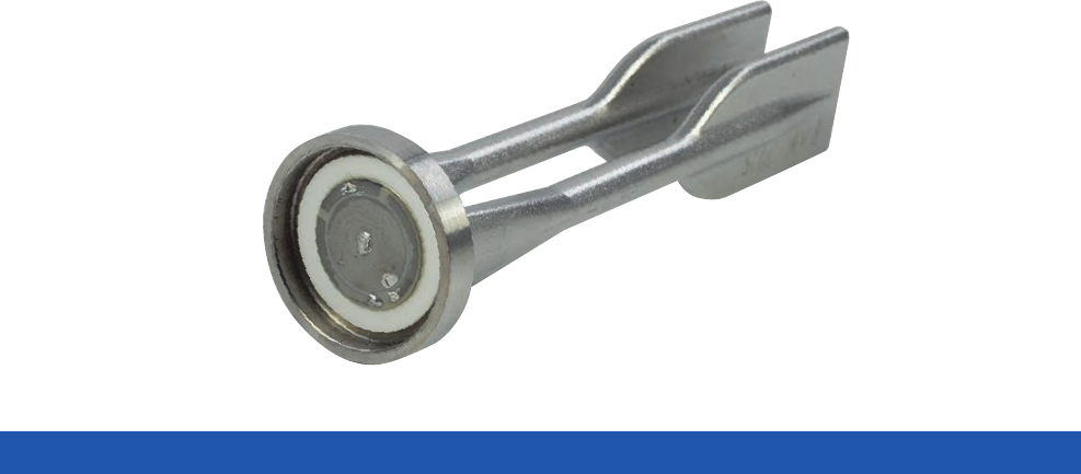
36
WWW.PICERAMIC.COM
Level Measurement
For propagation time measurements the
piezo transducer operates outside the
medium to be measured as both transmit-
ter and receiver. It emits an ultrasonic pulse
in air which is reflected by the content. The
propagation time required is a measure of
the distance travelled in the empty part of
the container.
This allows non-contact measurements
whereby the level of liquids, and also solids,
in silos for example, can be measured.
The resolution or accuracy depends on how
well the ultrasonic pulse is reflected by the
respective surface.
Submersible transducers, or tuning fork
sensors, are almost exclusively used as lev-
el switches; several of these sensors at dif-
ferent heights are required to measure the
level. The piezo transducer excites a tuning
fork at its natural frequency. When in con-
tact with the medium to be measured, the
resonance frequency shifts and this is eval-
uated electronically. This method works re-
liably and suffers hardly any breakdowns.
Moreover, it is independent of the type of
material to be filled.
Detection of Particles and Air Bubbles
The ultrasonic bubble sensor provides a
reliable control of liquid transport in tubes.
The sensor undertakes non-contact detec-
tion of the air and gas bubbles in the liq-
uid through the tube wall, and thus allows
continuous quality monitoring.
The application possibilities are in the
medical, pharmaceutical and food technol-
ogy fields. The sensors are used to mon-
itor dialysis machines, infusion pumps or
transfusions. Industrial applications include
control technology, such as the monitoring
of dosing and filling machines, for example.
Acceleration and Force Sensors,
Force Transducer
The key component of the piezoelectric
acceleration sensor is a disk of piezoelec-
tric ceramic which is connected to a seismic
mass. If the complete system is accelerated,
this mass increases the mechanical defor-
mation of the piezo disk, and thus increases
the measurable voltage. The sensors detect
accelerations in a broad range of frequencies
and dynamics with an almost linear char-
acteristic over the complete measurement
range.
Piezoelectric force sensors are suitable
for the measurement of dynamic tensile,
compression and shearing forces. They can
be designed with very high stiffness and can
also measure high-dynamic forces. A very
high resolution is typical.
Ultrasonic Sensors:
Piezo Elements in Metrology
Example of a tuning fork for level measurement,
OEM product
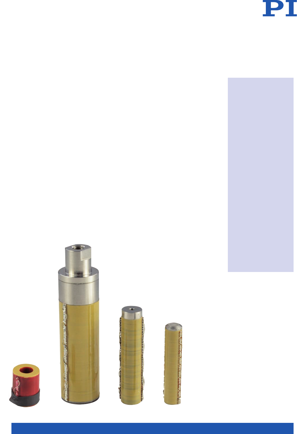
37
PIEZO TECHNOLOGY
Piezoelectric translators are ceramic solid
state actuators which convert electrical en-
ergy directly into linear motion with theo-
retically unlimited resolution. The length
of the actuator changes by up to 0.15 % in
this process. The actuators simultaneously
generate large static and dynamic forces.
Their special characteristics mean that piezo
actuators are ideal for semiconductor, opti-
cal and telecommunications applications.
They are also used in the automotive field,
in pneumatic valve technology and vibration
damping, and for micropumps.
PI Ceramic provides not only hundreds
of standard versions but also special cus-
tom-ized versions quickly and reliably. The
actuators can be equipped with position
sensors for applications requiring high
closed-loop linearity of motion.
Piezo Systems with
High Force Generation: PICA
So-called high-voltage piezo actuators are
manufactured from piezoceramic disks in
a stack construction. The individual layers
are produced by pressing technology. Ap-
plica-tions for the high-load actuators can
be found in mechanical engineering for out-
of-round rotations, for example, in active vi-
bration control or for switching applications.
Many modifications are possible:
! Customized materials
! Layer thickness and thus voltage range
! Dimensions and basic form
! Force ranges resp. custom load
! Design and material of end pieces
! Extra-tight length tolerances
! Integrated piezoelectric sensor disks
! Special high / low temperature versions
! Vacuum-compatible and non-magnetic
versions
Piezoelectric Actuators
Piezo Actuators from
PI Ceramic
! Motion with sub-
nanometer resolution
! High forces (up to
over 50,000 N), high
load capacity (up to
100 MPa)
! Microsecond
response
! Free of play and fric-
tion
! Minimum power
consumption when
maintaining its
position
! Non-wearing
! High reliability
(> 109 switching
cycles)
! Suitable for vacuum
use and cleanrooms
! Can operate at
cryogenic
temperatures
! Magnetic fields have
no influence and
are themselves not
influenced
Choice of piezo stack actuators
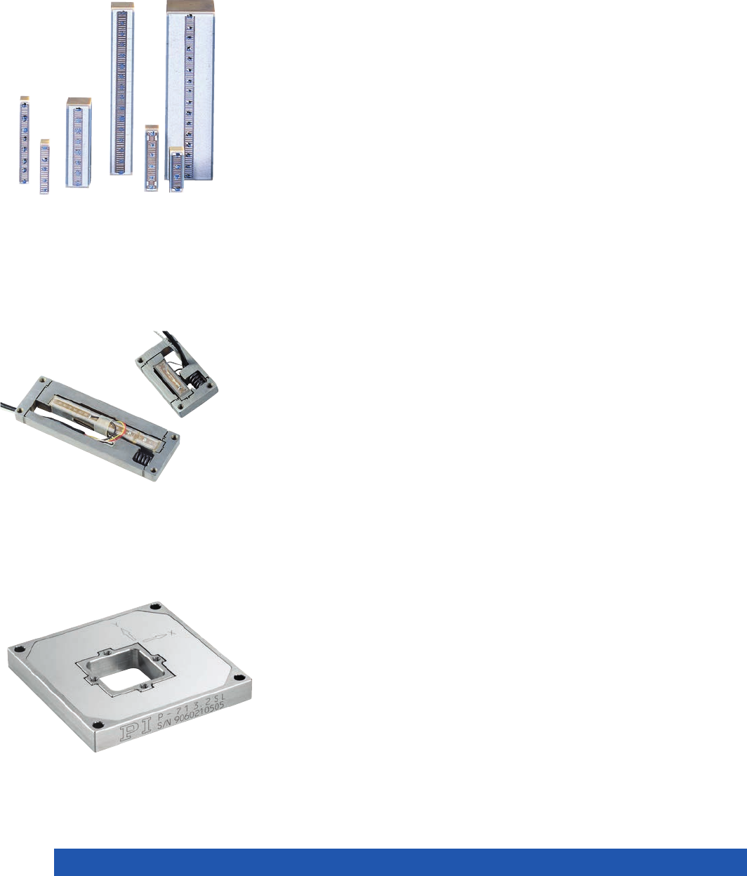
38
WWW.PICERAMIC.COM
Reliable Piezo Actuators with
Low Operating Voltage: PICMA®
PICMA® multilayer actuators are construct-
ed using tape technology and are subse-
quently sintered in the multilayer co-firing
process. The special PICMA® PZT ceramic
and its manufacturing technique produce an
ideal combination of stiffness, capacitance,
displacement, temperature stability and
lifetime. The typical operating voltage of the
PICMA® multilayer actuators is 100 to 120 V.
PICMA® piezo actuators are the only mul-
tilayer actuators in the world with ceramic
encapsulation. This technology protects the
PICMA® actuators from environmental influ-
ences, in particular humidity, and ensures
their extremely high reliability and perfor-
mance even under harsh industrial oper-
ating conditions. The lifetime of PICMA®
actuators is significantly better than that of
piezo actuators with conventional polymer
encapsulation.
Since PICMA® piezo actuators do not re-
quire additional polymer insulation and can
be operated up to 150 °C they are ideal for
use in high vacuum. They even work, at a
reduced travel, in the cryogenic temperature
range.
Many fields of application benefit from
this reliability: Precision engineering and
precision machining as well as switches
and pneumatic or hydraulic valves. Further
applications can be found in the fields of ac-
tive vibration control, nanotechnology, me-
trology, optics and interferometry.
Preloaded Actuators – Levers –
Nanopositioning
PICMA® piezo actuators from PI Ceramic
are the key component for nanoposition-
ing systems from Physik Instrumente (PI).
They are supplied in different levels of in-
tegration: As simple actuators with position
sensor as an optional extra, encased with
or without preload, with lever amplifica-
tion for increased travel, right through to
high-performance nanopositioning systems
where piezo actuators drive up to six axes by
means of zero-wear and frictionless flexure
guidings.
What they all have in common is a motion
resolution in the nanometer range, long
lifetimes and outstanding reliability. The
combination of PICMA® actuators, flex-
ure guiding and precision measurement
systems produces nanopositioning devices
in the highest performance class.
The fields of application range from
semiconductor technology, metrology,
microscopy, photonics through to bio-
technology, aerospace, astronomy and cryo-
genic environments.
Piezo nanopositioning system
with parallel kinematics and
displacement sensors
Piezoelectric PICMA® actuators
Lever amplified system
Piezoelectric Actuators

39
PIEZO TECHNOLOGY
If a mechanical system is knocked off
balance, this can result in vibrations which
adversely affect plants, machines and sen-
sitive devices and thus affect the quality of
the products. In many applications it is not
possible to wait until environmental influ-
ences dampen the vibration and bring it to
a halt; moreover, several interferences usu-
ally overlap in time, resulting in a quite con-
fusing vibration spectrum with a variety of
frequencies.
The vibrations must therefore be insulated
in order to dynamically decouple the ob-
ject from its surroundings and thus reduce
the transmission of shocks and solid-
borne sound. This increases the precision
of measuring or production processes
and the settling times reduce significant-
ly, which means higher throughputs are
possible. Piezoelectric components can
dampen vibrations particularly in the low-
er frequency range, either actively or pas-
sively.
Passive Vibration Insulation
Elastic materials absorb the vibrations and
reduce them. Piezo elements can also be
used for this: They absorb the mechani-
cal energy of the structural vibrations and
convert it into electrical energy at the same
time. This is subsequently converted into
heat by means of parallel electrical resistors,
for example.
Passive elements are installed as close to
the object to be decoupled as possible.
The conventional passive methods of vibra-
tion insulation are no longer sufficient for
many of today’s technologies. Movements
and jolts caused by footfall, fans, cooling
systems, motors, machining processes etc.
can distort patterns e.g. when micromachin-
ing to such an extent that the result is un-
usable.
Active Vibration Insulation
In this process, counter-motions compen-
sate or minimize the interfering vibrations,
and they do this as close to the source as
possible. To this end a suitable servo loop
must initially detect the structural vibrations
before the counter-motions are actively
generated.
Adaptive materials, such as piezoceram-
ic plates or disks, can act as both sensors
and actuators. The frequency range and the
mass to be damped determine the choice of
suitable piezo actuators. This also requires
an external voltage source and suitable
control electronics.
Multilayer ceramic construction produces
increased efficiency. Multilayer piezoelec-
tric actuators, such as the PICMA multilayer
translators, for example, can be used any-
where where precisely dosed alternating
forces are to act on structures.
The main application fields are in aero-
nautics and aerospace, where fuel must
be saved, for example, or the oscillations
of lattice constructions for antennas are to
be damped. One of the objectives when
building vehicles and ships is to minimize
noise in the interior. In mechanical engineer-
ing for example, the vibrations of rotating
drives are increasingly being insulated and
actively suppressed.
Vibration Control
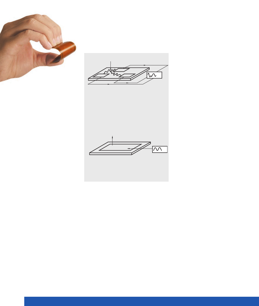
40
WWW.PICERAMIC.COM
Industrial Applications of the Future
The development of adaptive systems is
increasing in significance for modern in-
dustry. Intelligent materials are becoming
more and more important here, so-called
“smart materials“ which possess both sen-
sor and actu ator characteristics. They detect
changed environmental conditions such as
impact, pressure or bending loads and react
to them.
Piezo ceramics belong to this group of
adaptive materials. The piezoelectric Dura-
Act patch transducers provide a compact
solution. They are based on a thin piezo-
ceramic film which is covered with elec-
trically conducting material to make the
electrical contact and are subsequently
embedded in an elastic polymer composite.
The piezoceramic element, which is brittle
in itself, is thus mechanically preloaded and
electrically insulated and is so robust that it
can even be applied to curved surfaces with
bending radii of only a few millimeters.
The transducers are simply glued to the cor-
responding substrate or already integrated
into a structure during manufacture, where
they detect or generate vibrations or contour
deformations in the component itself. The
size of the contour change here is strong-
ly dependent on the substrate properties
and ranges from the nanometer up into the
millimeter range.
Even under high dynamic load the construc-
tion guarantees high damage tolerance, reli-
ability and a lifetime of more than 109 cycles.
They have low susceptibility to wear and
defects because the transducers are solid
state actuators and thus do not contain any
moving parts.
Adaptive Systems, Smart Structures
U
U
FF
A deformation of the substrate gives rise to an
electrical signal. The DuraAct transducer can
therefore detect deformations with precision
and high dynamics.
To dispense with the need for batteries and
the associated servicing work, it is possible
to use energy from the surrounding environ-
ment. Piezo elements convert kinetic energy
from oscillations or shocks into electrical
energy.
The robust and compact DuraAct trans-
ducers can also be used here. Deformations
of the substrate cause a deformation of the
DuraAct patch transducer and thus gener-
ate an electrical signal. Suitable transducer
and storage electronics can thus provide a
decentralized supply for monitoring systems
installed at locations which are difficult to
access.
Energy from Vibration – Energy Harvesting
The DuraAct patch transducer contracts when a
voltage is applied. Attached to a substrate it acts
as a bender element in this case.
U U
FF

41
PIEZO TECHNOLOGY
Ultrasonic applications for the machining
of materials are characterized mainly by
their high power density. The applications
typically take place in resonance mode in or-
der to achieve maximum mechanical power
at small excitation amplitude.
The ferroelectric “hard“ PZT materials are
particularly suitable for these high-power
ultrasonic machining applications. They
exhibit only low dielectric losses even in
continuous operation, and thus consequent-
ly only low intrinsic warming.
Their typical piezoelectric characteristics
are particularly important for the high me-
chanical loads and operating field strengths:
Moderate permittivity, large piezoelectric
coupling factors, high mechanical quality
factors and very good stability.
Ultrasound for Bonding:
Joining Techniques
Ultrasonic bonding processes can be used
to bond various materials such as thermo-
plastics, and metallic materials like aluminum
and copper and their alloys. This principle is
used by wire bonders in the semiconductor
industry and ultrasonic welding systems, for
example.
The ultrasonic energy is generated primarily
via mechanically strained piezo ring disks,
amplified by means of a so-called sonotro-
de and applied to the bond. The friction of
the bonding partners then generates the
heat required to fuse, or weld, the materials
together around the bond.
Shaping by Machining
Apart from the welding processes, the ul-
trasonic processing of hard mineral or cry-
stalline materials such as ceramic, graphite
or glass, especially by ultrasonic drilling or
machining, like vibration lapping, is increas-
ingly gaining in importance.
This makes it possible to produce geometri-
cally complex shapes and three-dimensional
contours, with only a small contact pressure
being required. Specially shaped sonotrodes
are also used here as the machining tool.
Ultrasonic Machining of Materials
Sonar Technology and Hydroacoustics
Sonar technology systems (sonar = sound
navigation and ranging) and hydroacou-
stic systems are used for measuring and
position-finding tasks especially in mari-
time applications. The development of
high-resolution sonar systems, which
was driven by military applications, is now
increasingly being replaced by civil applica-
tions.
Apart from still used submarine positioning
sonars, systems are used for depth measu-
rements, for locating shoals of fish, for sub-
surface relief surveying in shallow waters,
underwater communication, etc.
A diverse range of piezo components is
used, ranging from the simple disk or
plate and stacked transducers through
to sonar arrays which make it possible
to achieve a linear deflection of the directivi-
ty pattern of the ultrasonic wave.
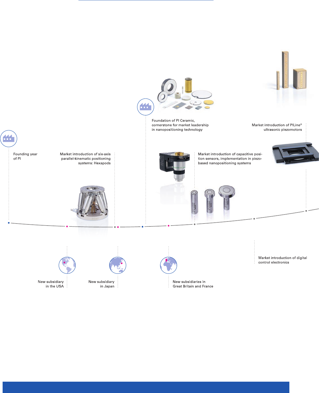
42
WWW.PICERAMIC.COM
70
WWW.PICERAMIC.COM
1992
1994
1998
2001
1987
1970
1991
1993
The PI Group Milestones
A SUCCESS STORY
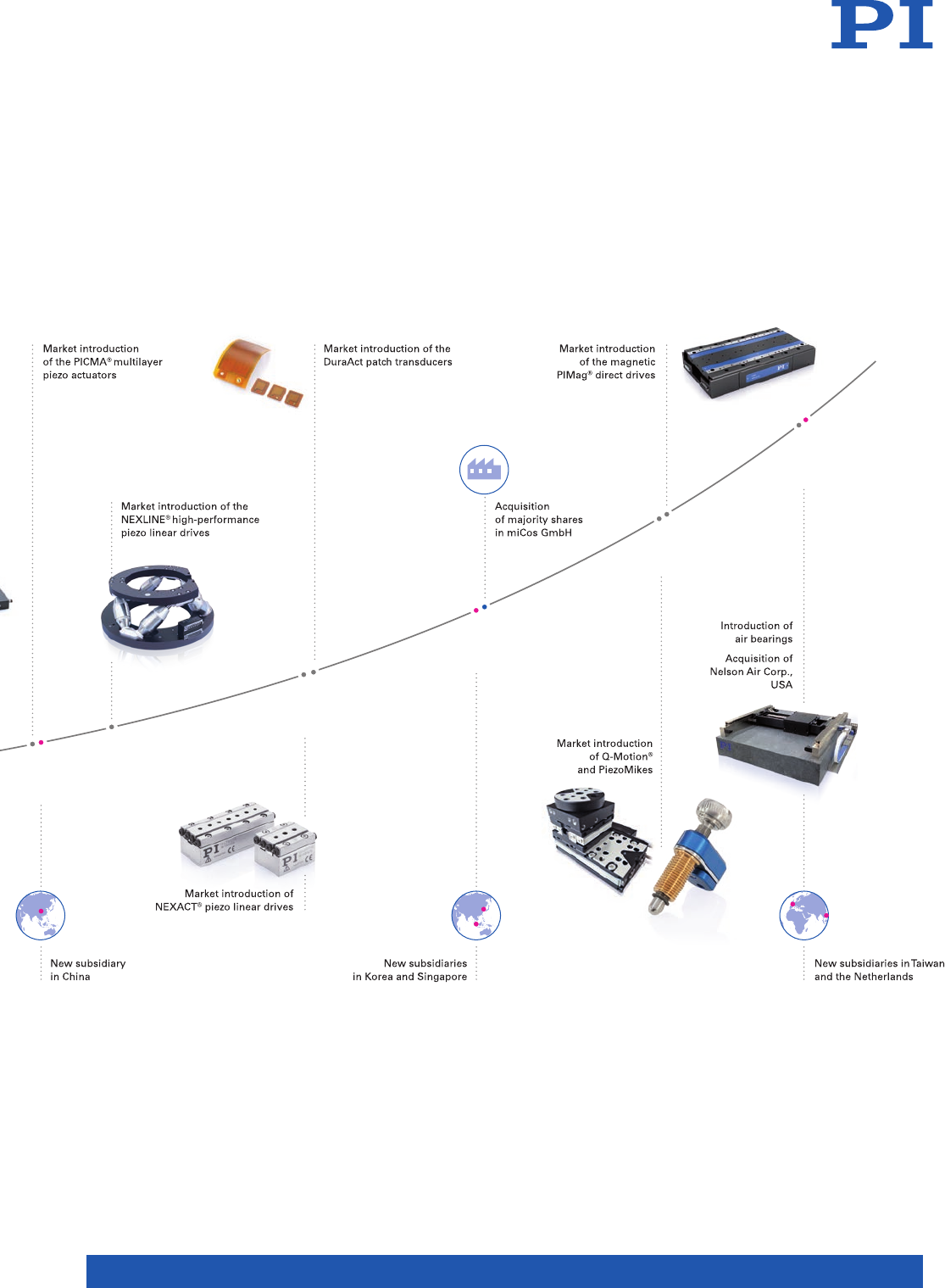
43
PIEZO TECHNOLOGY
71
PIEZO TECHNOLOGY
2004
2015
2002
2011
2014
2007

WWW.PICERAMIC.COM
CAT125E R3 Piezoelectric Ceramic Products 12/2016. 0; Subject to change without notice. © Physik Instrumente (PI) GmbH & Co. KG 2016
© Physik Instrumente (PI) GmbH & Co. KG
All contents, including texts, graphics, data etc., as well as their layout,
are subject to copyright and other protective laws. Any copying, modi-
fication or redistribution in whole or in parts is subject to a written
permission of PI.
Although the information in this document has been compiled with
the greatest care, errors cannot be ruled out completely. Therefore,
we cannot guarantee for the information being complete, correct and
up to date. Illustrations may differ from the original and are not bind-
ing. PI reserves the right to supplement or change the information
provided without prior notice.
Headquarters
GERMANY
PI Ceramic GmbH
Lindenstrasse
Lederhose
Phone +49 36604 882-0
Fax +49 36604 882-4109
info@piceramic.com
www.piceramic.com
Physik Instrumente (PI)
GmbH & Co. KG
Auf der Roemerstrasse 1
76228 Karlsruhe
Phone +49 721 4846-0
Fax +49 721 4846-1019
info@pi.ws
www.pi.ws
PI miCos GmbH
Freiburger Strasse 30
Eschbach
Phone +49 7634 5057-0
Fax +49 7634 5057-99
info@pimicos.com
www.pi.ws
Subsidiaries
USA (East) & CANADA USA (West) & MEXIKO
PI (Physik Instrumente) L.P.
Auburn, MA 01501
www.pi-usa.us
PI (Physik Instrumente) L.P.
Irvine, CA 92620
www.pi-usa.us
USA (San Francisco Bay Area Office) UK & IRELAND
PI (Physik Instrumente) L.P.
Sausalito, CA 94965
www.pi-usa.us
PI (Physik Instrumente) Ltd.
Cranfield, Bedford
www.physikinstrumente.co.uk
ITALY NETHERLANDS
Physik Instrumente (PI) S. r. l.
Bresso
www.pionline.it
PI Benelux B.V.
Sint-Oedenrode
www.pi.ws
FRANCE SPAIN
PI France SAS
Aix-en-Provence
www.pi.ws
Micos Iberia S.L.
Vilanova i la Geltrú
www.pimicos.es
JAPAN
PI Japan Co., Ltd.
Tokyo
www.pi-japan.jp
PI Japan Co., Ltd.
Osaka
www.pi-japan.jp
CHINA
Physik Instrumente
(PI Shanghai) Co., Ltd.
Shanghai
www.pi-china.cn
SOUTHEAST ASIA
Physik Instrumente
(PI Shanghai) Co., Ltd.
Beijing
www.pi-china.cn
TAIWAN
PI (Physik Instrumente)
Singapore LLP
Singapore
www.pi-singapore.sg
For ID / MY / PH / SG / TH / VNM
Physik Instrumente (PI)
Taiwan Ltd.
Taipei
www.pi-taiwan.com.tw
KOREA
PI Korea Ltd.
Seoul
www.pikorea.co.kr
PIEZO TECHNOLOGY
Visit us on
youtube!
