Pilz and KG PITM2 RFID Operating mode selector User Manual Manual
Pilz GmbH & Co. KG RFID Operating mode selector Manual
Manual

PITm2.1pDMG
OperatingManual1003182EN02
Operatorterminals

Preface
Thisdocumentistheoriginaldocument.
AllrightstothisdocumentationarereservedbyPilzGmbH&Co.KG.Copiesmaybemade
forinternalpurposes.Suggestionsandcommentsforimprovingthisdocumentationwillbe
gratefullyreceived.
Pilz®,PIT®,PMI®,PNOZ®,Primo®,PSEN®,PSS®,PVIS®,SafetyBUSp®,
SafetyEYE®,SafetyNETp®,thespiritofsafety®areregisteredandprotectedtrademarks
ofPilzGmbH&Co.KGinsomecountries.
SDmeansSecureDigital

Content
OperatingManualPITm2.1pDMG
1003182EN02 3
Section1 Introduction 5
1.1 Validityofdocumentation 5
1.1.1 Retainingthedocumentation 5
1.2 Definitionofsymbols 6
Section2 Overview 7
2.1 Featuresoftheoperatingmodeselectorswitch 8
2.2 Featuresofthetransponderkey 9
Section3 Safety 10
3.1 Intendeduse 10
3.2 Safetyregulations 11
3.2.1 Useofqualifiedpersonnel 11
3.2.2 Warrantyandliability 11
3.2.3 Disposal 11
Section4 Functiondescription 12
4.1 Interfaceforstatusinformation 14
4.1.1 Timingdiagramsforoperatoractions 16
4.1.2 Timingdiagramfordeviceerror 17
4.1.3 Timingdiagramsforusererror:"Noauthorisation" 18
4.1.4 Timingdiagramsforusererror:"Buttonoperatedincorrectly" 20
4.2 Operatingmodeinterface 22
4.2.1 Switchbehaviourafteratransponderkeyisremoved 22
4.2.2 Controlprogramrequirements 23
4.3 KeyIDinterface 24
4.3.1 KeyIDnumberofthetransponderkey 24
4.3.2 CommunicationmodefordownloadingtheKeyIDnumber 26
4.3.2.1 Transmittercontrolledcommunicationmode 26
4.3.2.2 Handshakecontrolledcommunicationmode 27
4.3.3 Evaluationbyacontrolsystem 28
4.3.3.1 EvaluationoftheKeyIDnumberwithtransmittercontrolledcommunication28
4.3.3.2 EvaluationoftheKeyIDnumberwithhandshakecontrolledcommunica
tion
31
Section5 Installation 35
5.1 Generalinstallationguidelines 35
5.2 Dimensions 36
Section6 Wiring 37
6.1 Terminalconfiguration 37
6.2 Connectingtheunit 38
6.3 Connectiontoacontrolsystem 39
Section7 Operation 42
7.1 SelectoperatingmodesOM1...OM4 43
7.2 SelectspecialmodeOM5(Service) 44

Content
OperatingManualPITm2.1pDMG
1003182EN02 4
7.3 Monitoringofoperatingtime 45
7.4 Switchoverdelayt1 45
7.5 Troubleshooting 46
7.6 Diagnostics 47
7.6.1 Statusinformationabouttheinterfaceforstatusinformation 47
7.6.2 Statusinformationaboutpushbuttonbacklighting 47
Section8 Technicaldetails 48
8.1 Safetycharacteristicdata 50
Section9 Supplementarydata 51
9.1 Radioapproval 51
Section10 Orderreference 52
10.1 Product 52
10.2 Accessories 52

Introduction
OperatingManualPITm2.1pDMG
1003182EN02 5
1 Introduction
1.1 Validityofdocumentation
ThisdocumentationisvalidfortheproductPITm2.1pDMG.Itisvaliduntilnewdocumenta
tionispublished.
Thisoperatingmanualexplainsthefunctionandoperation,describestheinstallationand
providesguidelinesonhowtoconnecttheproduct.
1.1.1 Retainingthedocumentation
Thisdocumentationisintendedforinstructionandshouldberetainedforfuturereference.
Introduction
OperatingManualPITm2.1pDMG
1003182EN02 6
1.2 Definitionofsymbols
Informationthatisparticularlyimportantisidentifiedasfollows:
DANGER!
Thiswarningmustbeheeded!Itwarnsofahazardoussituationthatposes
animmediatethreatofseriousinjuryanddeathandindicatespreventive
measuresthatcanbetaken.
WARNING!
Thiswarningmustbeheeded!Itwarnsofahazardoussituationthatcould
leadtoseriousinjuryanddeathandindicatespreventivemeasuresthatcan
betaken.
CAUTION!
Thisreferstoahazardthatcanleadtoalessseriousorminorinjuryplus
materialdamage,andalsoprovidesinformationonpreventivemeasures
thatcanbetaken.
NOTICE
Thisdescribesasituationinwhichtheproductordevicescouldbedam
agedandalsoprovidesinformationonpreventivemeasuresthatcanbe
taken.Italsohighlightsareaswithinthetextthatareofparticularimport
ance.
INFORMATION
Thisgivesadviceonapplicationsandprovidesinformationonspecialfea
tures.
Overview
OperatingManualPITm2.1pDMG
1003182EN02 7
2 Overview
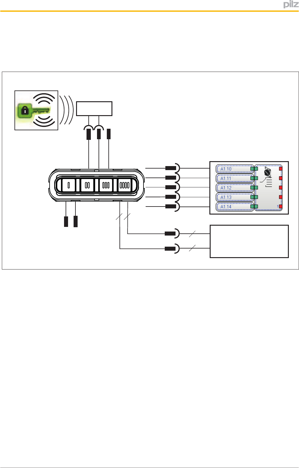
Theoperatingmodeselectorswitchmayonlybeoperatedinconjunctionwiththetranspon
derkeySmartkey®.6transponderkeysareavailable,eachwithdifferentauthorisations.
Transponder key
24 V DC
Evaluation device
Safety control system
(e.g. PNOZ m1p) with
"1oon" evaluation
Higher-level
process control system
IDo0 ... IDo3,
IDi0, IDi1
SIo0 ... SIo3
SOM1
SOM2
SOM3
SOM4
SOM5
Service
In n
In n+1
In n+2
In n+3
In n+4
A1
A2
Antenna +
Antenna -
n.c.
Antenna
6 4
6
4
Fig.:Operatingmodeselectorswitchinanapplication(principle)

Overview
OperatingManualPITm2.1pDMG
1003182EN02 8
2.1 Featuresoftheoperatingmodeselectorswitch
Theproducthasthefollowingfeatures:
}Supplyvoltage24VDC
}4pushbuttonsforswitchingtheoperatingmode
}Selectedoperatingmodeisdisplayedthroughpushbuttonbacklighting
}4operatingmodesOM1...OM4
}1specialmodeOM5(Service)
}1masterauthorisation
}5monitoredsemiconductoroutputs(24V)inaccordancewithEN614961;
1semiconductoroutputperoperatingmode
}Interfaceforstatusinformation,consistingof4signaloutputs(24V)
}Statusinformationisdividedintoinformationclasses:
– Operatoractions
Selecttransponderkey
Removetransponderkey
Selectoperatingmode
– Messages(e.g.usererror,fault)
}Interface(KeyIDinterface)fordownloadingtheKeyIDnumberofthetransponderkey
youareusing,consistingof
– 4semiconductoroutputs(24V)
– 2inputs
}ConfigurablecommunicationmodefordownloadingtheKeyIDnumber
– Transmittercontrolledcommunicationmode
– Handshakecontrolledcommunicationmode

Overview
OperatingManualPITm2.1pDMG
1003182EN02 9
2.2 Featuresofthetransponderkey
AtransponderkeycontainsaKeyIDnumberandtheauthorisationstowhichyoucan
switchwiththattransponderkey.
Features:
}Replacesthemechanicalkey
}Differentauthorisations
}Authorisationsareidentifiedviaprinted"KeyMode".

Safety
OperatingManualPITm2.1pDMG
1003182EN02 10
3 Safety
3.1 Intendeduse
Theoperatingmodeselectorswitchissuitableformachinesthatcanbeoperatedinmul
tipleoperatingmodeswithdifferentprotectivemeasuresand/orworkprocedures.Itenables
youtoswitchbetweendefinedoperatingmodes,suchas:
}Setupmode
}Manualmode
}Automaticmode
}Service
Theoperatingmodeselectorswitchmeetsthefollowingsafetyrequirements:
}Interlocktoprotectagainstunauthorisedswitching
Contactwithatransponderkeyisrequiredinordertoswitchtoanoperatingmode.
}Accessauthorisationsarerestrictedtocertaingroups
Atransponderkeywiththerelevantauthorisationisrequiredinordertoswitchtoacer
tainoperatingmode.
}Preventsunintentionalswitching
Theswitchtoadifferentoperatingmodeisonlyrecognisedoncethecorresponding
(selection)pushbuttonhasbeenoperatedforadefinedperiod("deliberateoperatorac
tion").Multipleoperationof(selection)pushbuttonsisdetected.
}Safe"1fromn"circuitoftheoperatingmodeoutputs
Theoperatingmodeselectorswitchonlyeverleadstooneoperatingmodeoutput"1"
signal.
ASmartkey®mustbeusedasthetransponderkey.
Dependingontheapplicationareaanditsrespectiveregulations,theoperatingmodese
lectorswitchcanbeuseduptoSILCL2(ENIEC62061)anduptoPLd
(ENISO138491),iftheoperatingmodesareevaluatedbyasafetycontrolsystemwith
safe"1oon"evaluation.
Switchingmustnotinitiateahazardousmovement,norcanitcancelanexistingcontrol
command.

Safety
OperatingManualPITm2.1pDMG
1003182EN02 11
3.2 Safetyregulations
3.2.1 Useofqualifiedpersonnel
Theproductsmayonlybeassembled,installed,programmed,commissioned,operated,
maintainedanddecommissionedbycompetentpersons.
Acompetentpersonissomeonewho,becauseoftheirtraining,experienceandcurrentpro
fessionalactivity,hasthespecialistknowledgerequiredtotest,assessandoperatethe
workequipment,devices,systems,plantandmachineryinaccordancewiththegeneral
standardsandguidelinesforsafetytechnology.
Itisthecompany’sresponsibilityonlytoemploypersonnelwho:
}Arefamiliarwiththebasicregulationsconcerninghealthandsafety/accidentpreven
tion
}Havereadandunderstoodtheinformationprovidedinthisdescriptionunder"Safety"
}Andhaveagoodknowledgeofthegenericandspecialiststandardsapplicabletothe
specificapplication.
3.2.2 Warrantyandliability
Allclaimstowarrantyandliabilitywillberenderedinvalidif
}Theproductwasusedcontrarytothepurposeforwhichitisintended
}Damagecanbeattributedtonothavingfollowedtheguidelinesinthemanual
}Operatingpersonnelarenotsuitablyqualified
}Anytypeofmodificationhasbeenmade(e.g.exchangingcomponentsonthePCB
boards,solderingworketc.).
3.2.3 Disposal
}Whendecommissioning,pleasecomplywithlocalregulationsregardingthedisposalof
electronicdevices(e.g.ElectricalandElectronicEquipmentAct).
Functiondescription
OperatingManualPITm2.1pDMG
1003182EN02 12
4 Functiondescription
Theoperatingmodeselectorswitchenablesyoutoswitchbetween5differentoperating
modes(operatingmodesOM1...OM4andspecialoperatingmodeOM5(Service)).
ForOM1...OM4,onebuttoneachisavailable.Forthespecialoperatingmode(Service),
buttonOM1mustbeoperatedforacertainperiod(seeMonitoringofoperating
time[ 45]).Eachbuttonisassignedamonitoredsemiconductoroutput.Operatingthe
buttonchangesthesemiconductoroutputfroma"0"signaltoa"1"signal.Theoperating
modeselectorswitchguaranteesthatonlyoneofthesemiconductoroutputshasa"1"sig
nalatanyonetime.
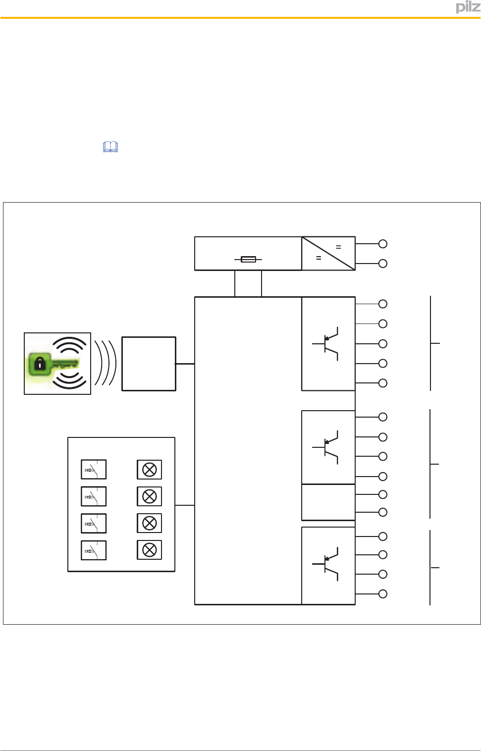
Transponder Key
RFID
Receiver
Power A1
A2
SOM1
SOM2
IDo0
IDo1
IDo2
IDo3
SOM3
SOM4
SOM5
User Interface
SIo0
SIo1
SIo2
SIo3
IDi0
IDi1
Inputs
Terminals
Key ID Interface (Safe) Operating Modes
Interface
Status Information
Interface
Fig.:Blockdiagram
Legend:
Transponderkey Electronickeytoenableachangeofoperatingmode
Userinterface Pushbuttontoselectanoperatingmode
A1,A2 Supplyvoltage
Functiondescription
OperatingManualPITm2.1pDMG
1003182EN02 13
SOM1…SOM5 Operatingmodeinterface
Interfacefordisplayingtheselectedoperatingmode;
consistsof5monitoredoutputs
IDo0…IDo3and
IDi0…IDi1
KeyIDinterface
InterfacefordownloadingtheKeyIDnumbertoacontrolsys
tem;consistsof4outputsand2inputs
SIo0…SIo3 Interfaceforstatusinformation
Interfaceforprovidingstatusinformation;
consistsof4signaloutputs
Theoperatingmodeselectorswitchisprotectedagainstunauthorisedoperation.Aswitch
betweenoperatingmodesmustbeenabledviaatransponderkey.
Transponderkeyauthorisations
Atotalof6transponderkeysareavailableforanoperatingmodeselectorswitch.Each
transponderkeyprovidesauthorisationtoswitchupto5operatingmodes,includingspecial
authorisations.Atransponderkeycanbeidentifiedviatheprintedkeymode.
Assignmentofkeymodestoauthorisations
Designation
Markingontransponder
key Authorisationforoperatingmode
KeyMode01 OM1
KeyMode02 OM1+OM2
KeyMode03 OM1+OM2+OM3
KeyMode04 OM1+OM2+OM3+OM4
KeyService OM1+OM2+OM3+OM4+OM5(Ser
vice)+Masterauthorisation
KeyMaster OM1+OM2+OM3+OM4+Masterau
thorisation
Masterauthorisation("KeyMaster")
Withmasterauthorisation,theusercanbegrantedspecialauthorisationonthemachine
controlsystemviatheKeyIDnumber.The"KeyMaster"transponderkeycanbeusedto
selectOM1...OM4.

Functiondescription
OperatingManualPITm2.1pDMG
1003182EN02 14
4.1 Interfaceforstatusinformation
Variousstatusinformationcanbesignalledviatheinterfaceforstatusinformation(see
Blockdiagram[ 12]).Thestatusinformationcanbeevaluatedthroughacontrolsystem.
Thestatusinformationissubdividedintothefollowinginformationclasses:
}Operatoractions
– Inserttransponderkey
– Removetransponderkey
– Selectoperatingmode
}Messages(e.g.usererror,fault)
NOTICE
Whentheoperatingmodeisselected(SIo3…SIo0=3h,8h...Bh)and
whenthereisadeviceerror(Dh)theinformationremainsindefinitely
present.Allotherinformationstaysactiveforjust200ms.Afterthattimethe
selectedoperatingmodeisagaindisplayed.
Statusinformation Informationclass
SIo3
(MSB) SIo2 SIo1
SIo0
(LSB)
Value
(in
Hex)
Reserved 0 0 0 0 0h
Reserved 0 0 0 1 1h
Transponderkey5–Inserted[1] Operatoraction 0 0 1 0 2h
OM5selected Operatoraction 0 0 1 1 3h
Transponderkey1–Inserted[1] Operatoraction 0 1 0 0 4h
Transponderkey2–Inserted[1] Operatoraction 0 1 0 1 5h
Transponderkey3–Inserted[1] Operatoraction 0 1 1 0 6h
Transponderkey4–Inserted[1] Operatoraction 0 1 1 1 7h
OM1selected Operatoraction 1 0 0 0 8h
OM2selected Operatoraction 1 0 0 1 9h
OM3selected Operatoraction 1 0 1 0 Ah
OM4selected Operatoraction 1 0 1 1 Bh
Noauthorisation[2] Usererror 1 1 0 0 Ch
Deviceerror[3] Error 1 1 0 1 Dh
Pushbuttonoperatedincorrectly[4] Usererror 1 1 1 0 Eh
Transponderkeyremoved Operatoraction 1 1 1 1 Fh

Functiondescription
OperatingManualPITm2.1pDMG
1003182EN02 15
[1]Whenapushbuttonisreleased,informationastowhichtransponderkeyisusedwillbe
displayedfor200ms(seeStatusinformation2hand4h…7h).Theselectedoperating
modeisthendisplayed(seeStatusinformation3hand8h…Bh).
PleaserefertotheTimingdiagramsforoperatoractions[ 16].
[2]Thefault"Noauthorisation"(Ch)isregisteredinthefollowingcases:
}Operatingmodeselectedwithouttransponderkey
}Operatingmodeselectedwithatransponderkeythatisnotauthorisedfortheselected
operatingmode
}Transponderkeyisnotauthorisedfortheactiveoperatingmode
}Transponderkeyisnotinsertedintimebeforetheoperatingmodeisselected
PleaserefertotheTimingdiagramsforusererror:"Noauthorisation"[ 18].
[3]"Deviceerror"(Dh)issignalledintheeventofaninternaldeviceerrororwhenoneof
theoperatingmodeoutputsSOM1...SOM5arestuckbecauseofexternalvoltage(stuck
at1orstuckat0).
Remedy:
}Rectifyerror,switchsupplyvoltageoffandthenonagain
}Changetheunit
PleaserefertotheTimingdiagramfordeviceerror[ 17].
[4]Thefault"Pushbuttonoperatedincorrectly"(Eh)isdisplayedinthefollowingcases:
}Multipleoperationofpushbuttons
}Pushbuttonoperatedfortoolong(timeoutforOM1toOM4=5sandtimeoutforOM5=
10s)
Note:Ifakeyisoperatedfor<50msthiswillnotbeevaluated,sotherewillbenore
action.
}Pushbuttonwasreleasedafterthetransponderkeywasremoved
PleaserefertotheTimingdiagramsforusererror:"Buttonoperatedincorrectly"[ 20].
Functiondescription
OperatingManualPITm2.1pDMG
1003182EN02 16
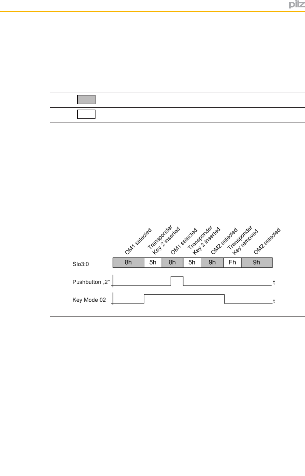
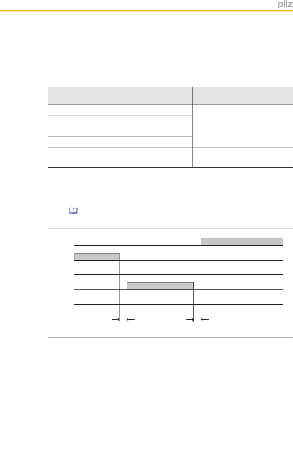
4.1.1 Timingdiagramsforoperatoractions
ThefollowingtimingdiagramsshowhowstatusinformationisregisteredatoutputsSlo0...
Slo3,basedonoperatoractions.
Legend:
Messageisdisplayedconstantly
Messageisdisplayedbriefly(200ms)
Selectoperatingmode
1. Startposition:OM1isselected
2. Operatoraction:Inserttransponderkey
(e.g.AuthorisationKeyMode02)
3. Operatoraction:Selectoperatingmode
(e.g.Presspushbutton"2"forOM2)
4. Operatoraction:Removetransponderkey
Fig.:Timingdiagramfor"Selectoperatingmode"
Functiondescription
OperatingManualPITm2.1pDMG
1003182EN02 17
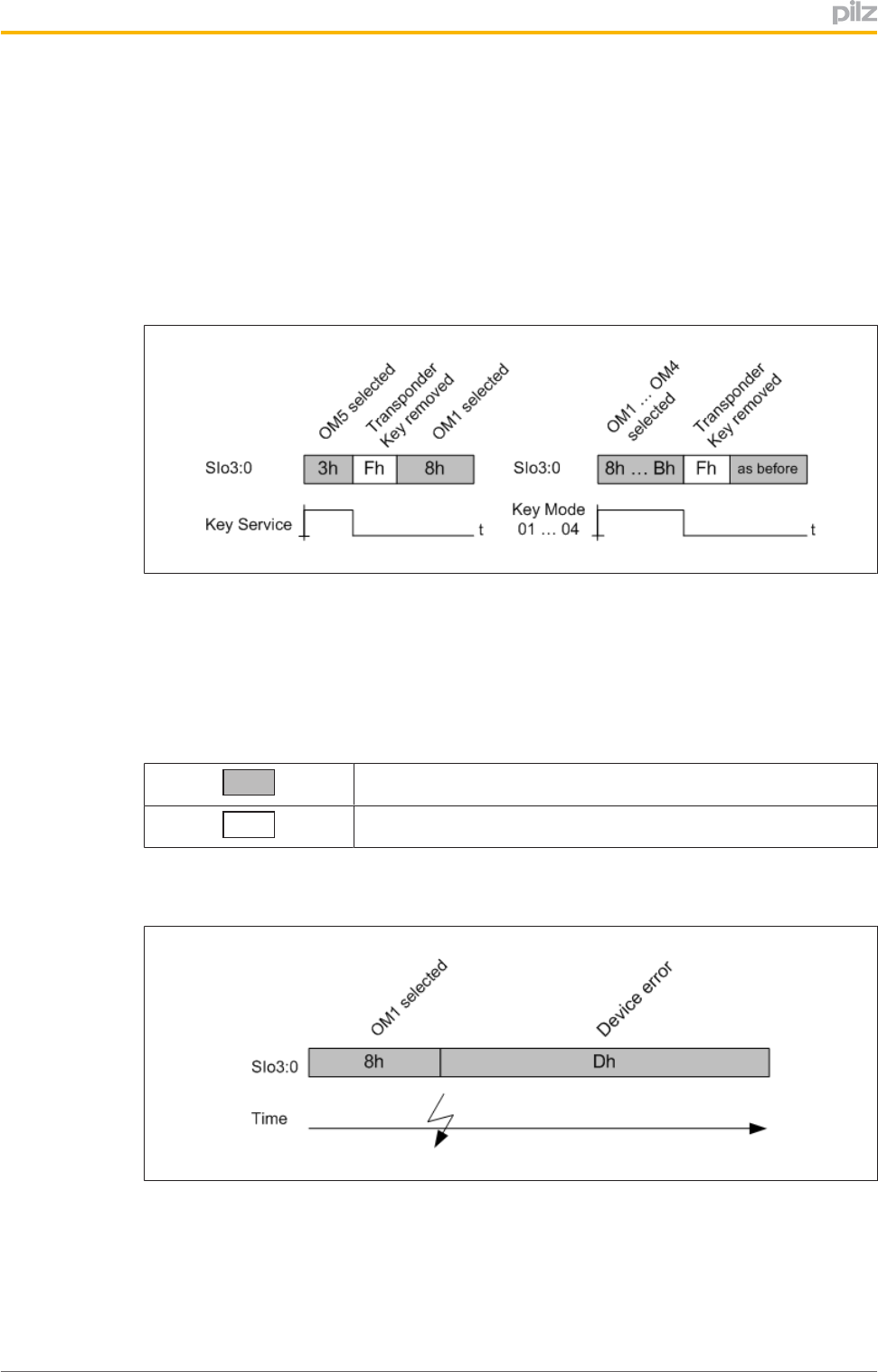
Removetransponderkey
1. Startposition:
– OM5isselectedandthetransponderkey"KeyService"isinserted
or
– OneoftheoperatingmodesOM1…OM4isselectedandatransponderkeywith
therelevantauthorisationisinserted
2. Operatoraction:Removetransponderkey
Fig.:Timingdiagramfor"Removetransponderkey"
4.1.2 Timingdiagramfordeviceerror
ThefollowingtimingdiagramshowshowstatusinformationisregisteredatoutputsSlo0...
Slo3,basedonadeviceerror.
Legend:
Messageisdisplayedconstantly
Messageisdisplayedbriefly(200ms)
Deviceerror
Fig.:Timingdiagramintheeventofadeviceerror
Functiondescription
OperatingManualPITm2.1pDMG
1003182EN02 18
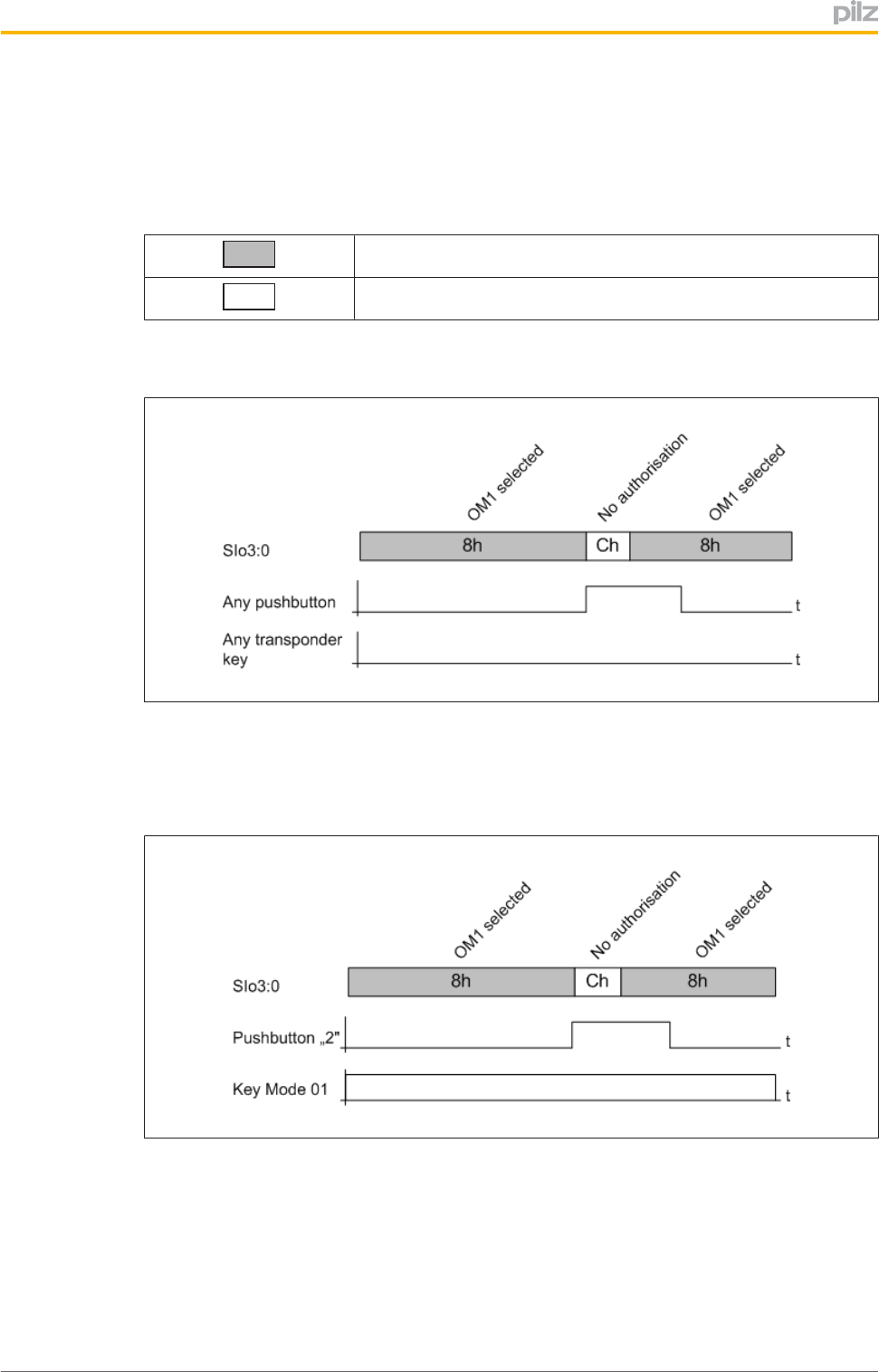
4.1.3 Timingdiagramsforusererror:"Noauthorisation"
ThefollowingtimingdiagramshowshowstatusinformationisregisteredatoutputsSlo0...
Slo3,basedontheusererror"Noauthorisation".
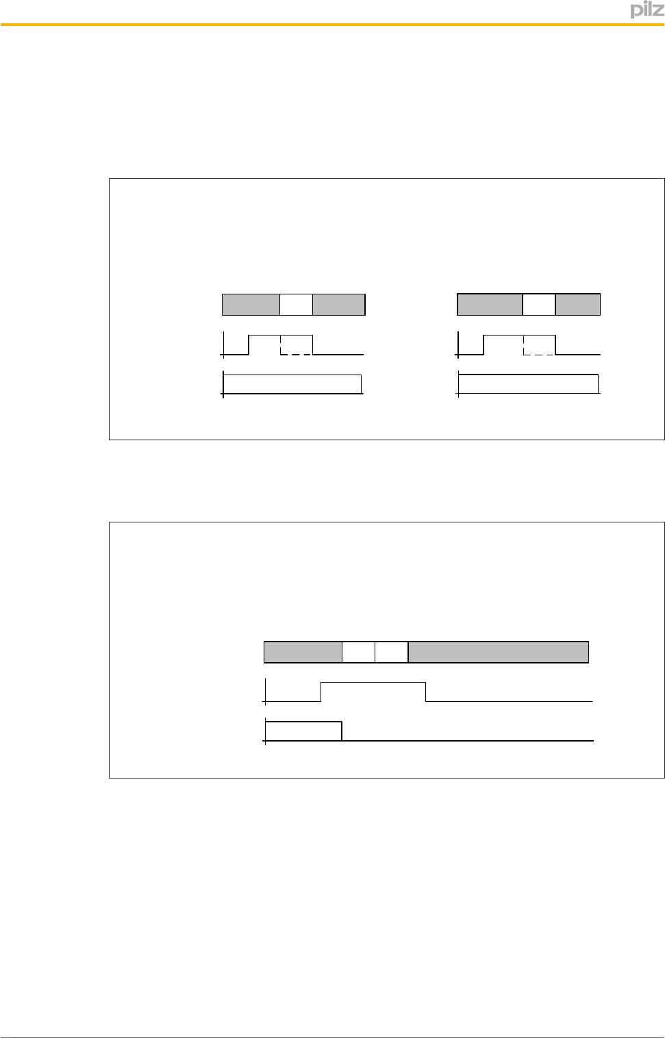
Legend:
Messageisdisplayedconstantly
Messageisdisplayedbriefly(200ms)
Operatingmodeselectedwithouttransponderkey
Fig.:Timingdiagramfor"Operatingmodeselectedwithouttransponderkey"
Operatingmodeselectedwithatransponderkeythatisnotauthorisedfortheselec
tedoperatingmode
Fig.:Timingdiagramforoperatingmodeselectionwherethereisinsufficientauthorisationfortheop
eratingmoderequiringselection
Functiondescription
OperatingManualPITm2.1pDMG
1003182EN02 19
Operatingmodeselectedwithatransponderkeythatisnotauthorisedfortheactive
operatingmode
SIo3:0
Key Mode 01
Pushbutton
9h
OM2 selected
Ch 9h
OM2 selected
No authorisation
4h
Transponder
Key 1 inserted
t
t
Fig.:Timingdiagramforoperatingmodeselectionwherethereisinsufficientauthorisationfortheact
iveoperatingmode
Transponderkeyisnotinsertedintimebeforetheoperatingmodeisselected
SIo3:0
Key Mode 02
Pushbutton „2"
8h
OM1 selected
Ch 8h
OM1 selected
5h
Transponder
Key 2 inserted
No authorisation
8h
OM1 selected
t
t
Fig.:Timingdiagramforselectingtheoperatingmodebeforethetransponderkeyisinserted
Functiondescription
OperatingManualPITm2.1pDMG
1003182EN02 20
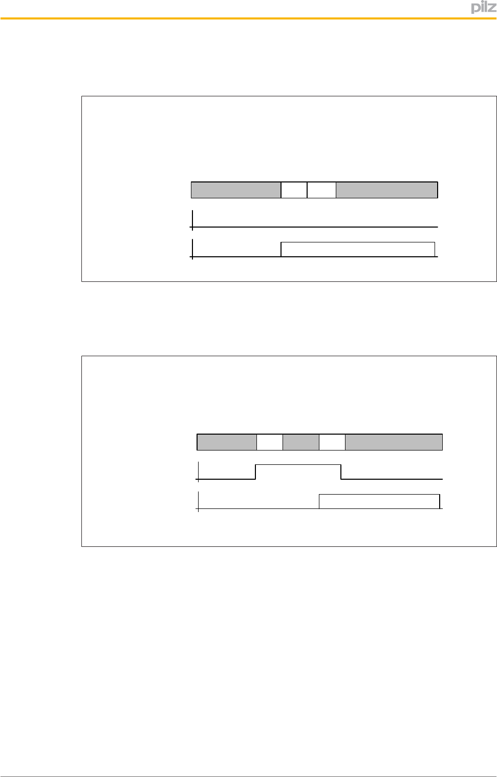
4.1.4 Timingdiagramsforusererror:"Buttonoperatedincorrectly"
ThefollowingtimingdiagramshowshowstatusinformationisregisteredatoutputsSlo0...
Slo3,basedontheusererror"Buttonoperatedincorrectly"
Legend:
Messageisdisplayedconstantly
Messageisdisplayedbriefly(200ms)
Multipleoperationofpushbuttons
Fig.:Timingdiagramfor"Multipleoperationofbuttons"
Functiondescription
OperatingManualPITm2.1pDMG
1003182EN02 21
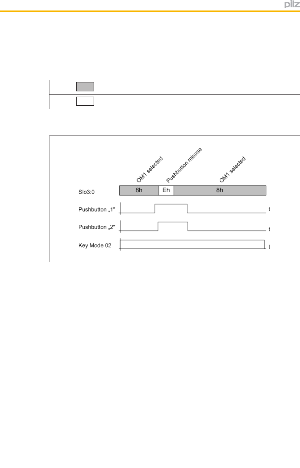
Buttonoperatedfortoolong
}"Buttonoperatedfortoolong"withauthorisations"KeyMode01"…"KeyMode04"
or
}"Buttonoperatedfortoolong"withauthorisation"KeyService"
SIo3:0 8h
OM1 selected
Eh 8h
OM1 selected
Pushbuttons
„1" … „4"
Key Mode 04
5 s
Pushbutton misuse
Pushbutton
„1"
Key Service
10 s
8h Eh 8h
OM1 selected
OM1 selected
Pushbutton misuse
t
t
SIo3:0
t
t
Fig.:Timingdiagramfor"Buttonoperatedfortoolong"
Pushbuttonwasreleasedafterthetransponderkeywasremoved
SIo3:0
Pushbutton „2"
8h
OM1 selected
Fh 8h
OM1 selected
Key Service
Transponder Key
removed
t
t
Eh
Pushbutton misuse
Fig.:Timingdiagramforusererrorswhenreleasingthebutton

Functiondescription
OperatingManualPITm2.1pDMG
1003182EN02 22
4.2 Operatingmodeinterface
TheoperatingmodeinterfaceconsistsofthemonitoredoutputsSOM1…SOM5(seeBlock
diagram[ 12])."SOM"standsfor"SafeOperatingMode".Theoutputsareassignedto
buttons,whichcanbeusedtoselectanoperatingmodeiftheyhavetherelevantauthorisa
tion(transponderkey):
Pushbutton Output Operatingmode
1 SOM1 OM1 TheoperatingmodeOM1/OM5isselected
basedontheoperatingtimeofbutton1(see
Monitoringofoperatingtime[ 45])
SOM5 OM5
2 SOM2 OM2
3 SOM3 OM3
4 SOM4 OM4
4.2.1 Switchbehaviourafteratransponderkeyisremoved
Thechangeofoperatingmodeiscompletedbyremovingthetransponderkey.Oncethe
transponderkeyhasbeenremoved,theoperatingmodeselectorswitchbehavesasfol
lows:
Selectedoperat
ingmode Assignedoutput
Behaviourafterthetransponderkeyisre
moved
OM1 SOM1 }Thepreviouslyselectedoperatingmodeis
maintained.
}Theassignedpushbuttonisbacklit.
}Theassignedoutputhasa"1"signal.
OM2 SOM2
OM3 SOM3
OM4 SOM4
OM5 SOM5 }SwitchtoOM1
}Pushbutton1isbacklit
}SOM1hasa"1"signal

Functiondescription
OperatingManualPITm2.1pDMG
1003182EN02 23
4.2.2 Controlprogramrequirements
InordertoachieveSILCL2(ENIEC62061)/PLd(ENISO138491)inanapplication,the
evaluationmustbecarriedoutbyasafetyrelatedfunctionblock.Thesafetyrelatedfunc
tionblockmustmeetthefollowingrequirements:
}Thefunctionblockmustenablesafe"1oon"evaluationoftheoutputsignalsatSOM1...
SOM5.
}Iftwoormoreoperatingmodesarepresentatthesametime,thismustbedetectedas
anerror.
INFORMATION
Thefunctionblockmustbridgethet1switchoverdelay(seeSwitchover
delayt1[ 45]).
IfaPNOZmulti(e.g.PNOZm1p)isusedasthesafetycontrolsystemin
conjunctionwithan"operatingmodeselectorswitch"functionelement,then
thisrequirementismetautomatically.
Functiondescription
OperatingManualPITm2.1pDMG
1003182EN02 24
4.3 KeyIDinterface
TheKeyIDinterface(seeBlockdiagram[ 12])isusedtodownloadtheKeyIDnumber
toacontrolsystem.
4.3.1 KeyIDnumberofthetransponderkey
TheKeyIDnumberisusedtoclearlyidentifythetransponderkeyandisunique.Itisprin
tedonthetransponderkey’stypelabelasa9digitdecimalfigure.
NOTICE
Pleasenote:
TheKeyIDnumberisnotprintedonthetransponderkeypackaging.
Ifthetransponderkeyislost,itisimpossibletosupplyareplacement
transponderkeywithanidenticalKeyIDnumber.
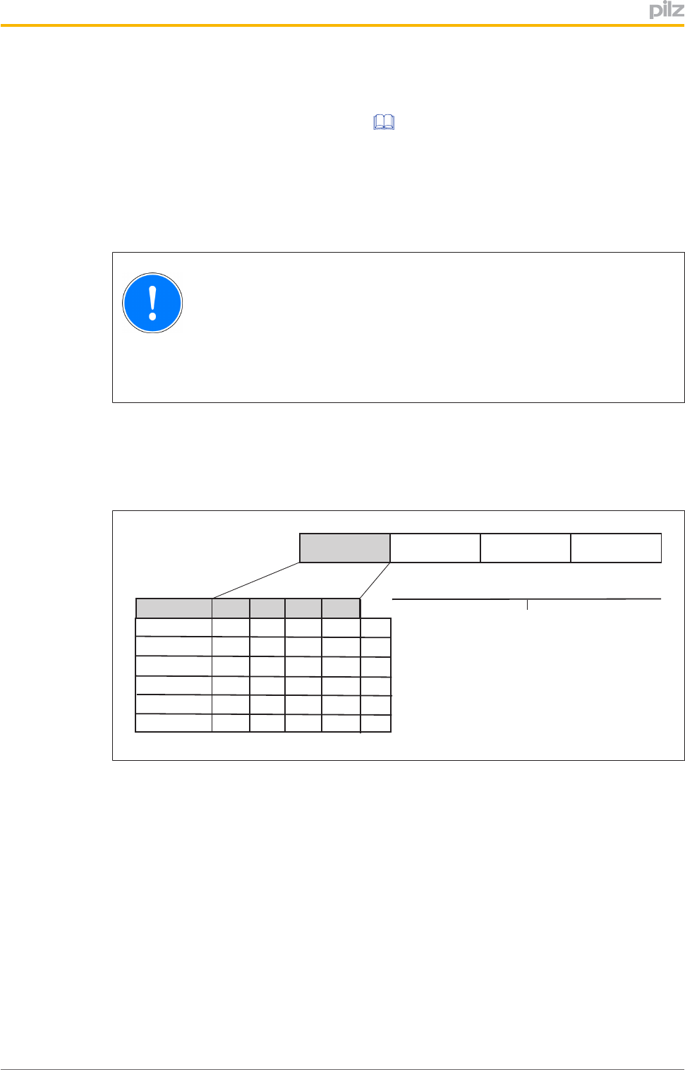
TheKeyIDnumberconsistsoftwoparts:
}Bit27=24:KeyMode(0…15D)
}Bit23=00:Consecutivenumber(0…999999999D)
Bit27 ... Bit24 Bit23 ... Bit16 Bit07 ... Bit00
Consecutive Number
Key Mode Bit27 Bit26 Bit25 Bit24
01 0 0 0 1 1D
02 0 0 1 0 2D
03 0 0 1 1 3D
04 0 1 0 0 4D
Service 1 1 0 1 13D
Master 1 1 0 0 12D
Bit15 ... Bit08
0 ... 15D0 ... 999999999D
Fig.:StructureoftheKeyIDnumber

Functiondescription
OperatingManualPITm2.1pDMG
1003182EN02 25
Examples:
1101 0000 0000 0010 1100
Consecutive number: 44D
0000 0000
Key Mode Service
Key-ID-Number: 130000044
0010 0000 0000 1111 1110
Consecutive number: 510D
0000 0001
Key Mode 02
Key-ID-Number: 020000510

Functiondescription
OperatingManualPITm2.1pDMG
1003182EN02 26
4.3.2 CommunicationmodefordownloadingtheKeyIDnumber
TheuniqueKeyIDnumberfortherelevanttransponderkeyisdownloadedtothehigher
levelprocesscontrolsystemusingadefinedprotocol,dependingontheconfiguredcom
municationmode.ThecommunicationmodeisconfiguredontheKeyIDinterfaceofthe
operatingmodeselectorswitch(jumpersavailable/notavailable).
Theoperatingmodeselectorswitchdetectstheconfiguredcommunicationmodeateach
poweron.Aslongasvoltageisappliedtotheoperatingmodeselectorswitch,thecon
figuredcommunicationmodewillbeactive;thechangeincommunicationmodedoesnot
comeintoeffectuntilthesupplyvoltageisswitchedoffandthenonagain.
It’spossibletochoosebetweenthefollowingcommunicationmodes:
}Transmittercontrolledcommunicationmode
}Handshakecontrolledcommunicationmode
4.3.2.1 Transmittercontrolledcommunicationmode
Withtransmittercontrolledcommunicationmode,thedownloadoftheKeyIDnumberis
startedbytheoperatingmodeselectorswitch(=transmitter).
Featuresofthiscommunicationmode:
}DownloadofKeyIDnumberstartsoncethetransponderkeyisconnected
}Constantbitrate(100ms)
}Downloadon2datalines
}Constantdownloadtime(typ.1.8s)
}Monitoreddatadownload
}Input/outputsrequiredonthecontrolsystem:4inputsand2outputs
}Downloadisrepeatedbyreconnectingthetransponderkey
or
ifthetransponderkeyisinserted,viathecontrolsystembysendinga"1"signaltoIDi0
foratleast50ms.
NospecialcodingisrequiredontheKeyIDinterfaceinordertodownloadtheKeyIDnum
berofatransponderkeytothecontrolsystemintransmittercontrolledcommunication
mode.TheterminalsontheKeyIDinterfaceareusedasfollows:
KeyIDinterface
Briefdescriptionofapplic
ation Codingviajumpers
IDo0 IDsync Noconfigurationrequired
IDo1 IDclock
IDo2 IDout0
IDo3 IDout1
IDi0 IDin0
IDi1 IDin1

Functiondescription
OperatingManualPITm2.1pDMG
1003182EN02 27
4.3.2.2 Handshakecontrolledcommunicationmode
Withhandshakecontrolledcommunicationmode,thedownloadoftheKeyIDnumberis
startedbythecontrolsystem(Request).
Featuresofthiscommunicationmode:
}Downloadstartsviaarequesttothecontrolsystem,oncethetransponderkeyiscon
nected
}Downloadisrepeatedbyarenewedrequesttothecontrolsystem
}Variablebitrate(min.2PLCcyclesperbit)
}Downloadon1dataline
}Min.downloadtime:28Bit*(20ms+2*PLCcycle)
}IdentifierforIDendforfeasibilitycheck
}Input/outputsrequiredonthecontrolsystem:3inputsand1output
TheKeyIDinterfacemustbecodedwithajumperbetweenIDo3andIDi1inordertodown
loadtheKeyIDnumberofatransponderkeytothecontrolsysteminhandshakecontrolled
communicationmode.TheterminalsontheKeyIDinterfaceareusedasfollows:
KeyIDinterface
Briefdescriptionofapplic
ation Codingviajumpers
IDo0 IDsync
IDi1 Coding: IN
IDo3 Coding: OUT
IDo1 IDresponse
IDo2 IDdata
IDo3 Coding:OUT
IDi0 IDrequest
IDi1 Coding:IN
Inhandshakecontrolledcommunicationmode,theoperatingmodeselectorswitchcanbe
operatedinafunctionalvariant.InthiscasetheKeyIDnumberofthetransponderkeyis
notdownloadedtothecontrolsystem.ThecontrolsystemisonlyusedtoevaluateIDo0on
theKeyIDinterface.InthiscaseIDo0isusedasasignaloutput,enablingthecontrolsys
temtorecognisewhetherthetransponderkeyisvalid/invalid.Withthisfunctionalvariant,
only1inputisrequiredonthecontrolsystem.TheunusedterminalsontheKeyIDinterface
(IDo1,IDo2andIDi0)mayremainunwired("open").
Functiondescription
OperatingManualPITm2.1pDMG
1003182EN02 28
4.3.3 Evaluationbyacontrolsystem
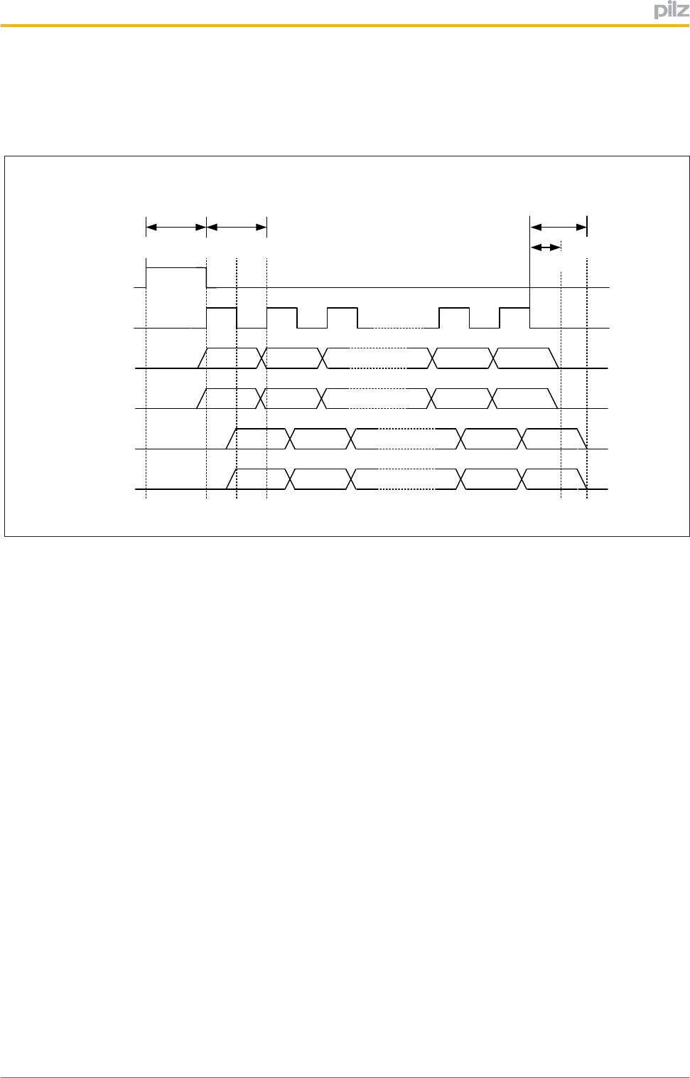
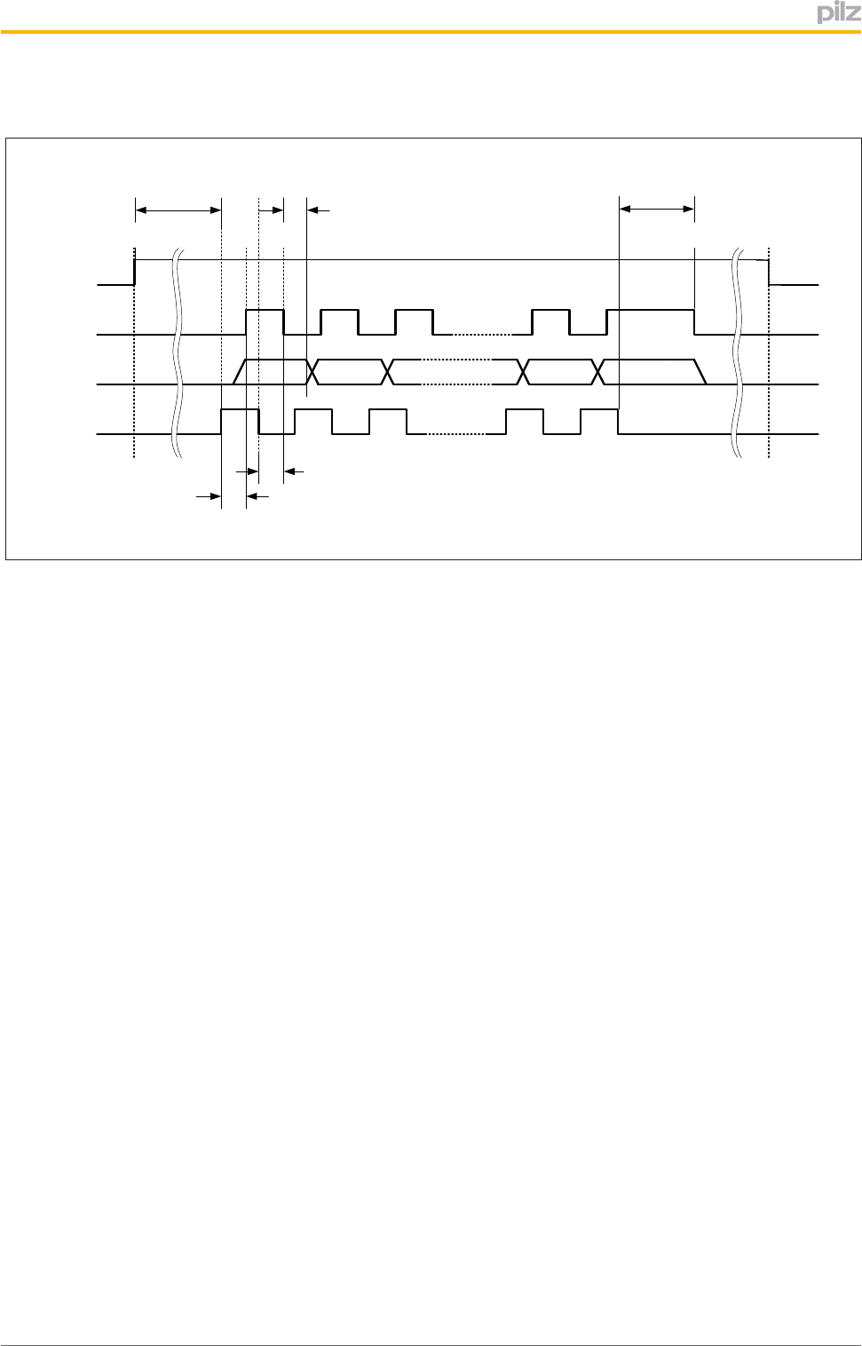
4.3.3.1 EvaluationoftheKeyIDnumberwithtransmittercontrolledcommunication
IDo0
(IDsync)
Bit 27 Bit 25 … Bit 16 Bit 15
Bit 14
IDo2
(IDout0) Bit 26
[c]
[d]
ten
IDo1
(IDclock)
[b]
max. 100 ms
Bit 13 Bit 11 … Bit 02 Bit 11
Bit 00
IDo3
(IDout1) Bit 12
Bit 27
Bit 25 … Bit 16 Bit 15 Bit 14
IDi0
(IDin0) Bit 26
Bit 13
Bit 11 … Bit 02 Bit 11
Bit 00
IDi1
(IDin1) Bit 12
T
[a]
min. 60 ms [f]
[e]
Fig.:Timingdiagramfortransmittercontrolledsignaldownload
Legend:
Theadditionalterminaldesignations(IDsync,IDclock,IDout0etc.)areabbreviationsfor
theterminalsignal'sapplication.
IDo0 Controlline
Thesignalisgeneratedbytheoperatingmodeselectorswitch.
"0"signal Notransponderkeyisconnectedorthetransponderkeythat
isconnectedisinvalid.
"1"signal Avalidtransponderkeyiscreated.Theoperatingmodese
lectorswitchsignalstothecontrolsystemwhenthedown
loadstarts.Thesignalispresentfor100ms.
IDo1 Testpulseline
Thesignalisgeneratedbytheoperatingmodeselectorswitchandindic
atesthevalidityofthedatabitsatIDo2andIDo3.
}T=100ms
}Dutycycle=50%
IDo2,IDo3 DatalinesfortransmittingtheKeyIDnumber
TheoperatingmodeselectorswitchsendstheKeyIDnumbertothecon
trolsystemviathesetwodatalines.
IDo2: SendBit27…Bit14
IDo3 SendBit13…Bit00
IDi0,IDi1 DatalineforreadingbacktheKeyIDnumber
ThecontrolsystemsendsthepreviouslyreceivedKeyIDnumberbackto
theoperatingmodeselectorswitchviathesetwodatalines.
IDi0: ReceiveBit27…Bit14
IDi1 ReceiveBit13…Bit00

Functiondescription
OperatingManualPITm2.1pDMG
1003182EN02 29
Downloadprocedure
[a] TheoperatingmodeselectorswitchsetsthesignalatIDo0(IDsync:control
line)to"1"for100ms,therebysignallingtothecontrolsystemthattransmis
sionhasstarted.
[b] ArisingedgeatIDo1(IDclock:testpulseline)indicatesthatthedataatdata
linesIDo2andIDo3ispresentandvalidandcanbereadbythecontrolsys
tem.
[c] BythetimethereisafallingedgeatIDo1(IDclock:testpulseline),thecontrol
systemmusthavesentthepreviouslyreadbitbacktotheoperatingmodese
lectorswitchviathedatalinesIDi0andIDi1.
[d] BeforetherisingedgeatIDo1(IDclock:testpulseline),theoperatingmode
selectorswitchreadsthebitssentbacktoIDi0andIDi1bythecontrolsystem
andchecksitforequivalence.
[e] Atleast60msafterthefallingedgeatIDo1(IDclock:testpulseline),thelast
bitsentbackbythecontrolsystemmustbepresentatdatalinesIDi0and
IDi1.
[f] Amaximumof100msafterthefallingedgeatIDo1(IDclock:testpulseline),
thelastbitsentbackbythecontrolsystemmustbepresentatdatalinesIDi0
andIDi1;inotherwords,bythispointatthelatest,datatransfermustbecom
pletedandthedatalinesmusthavea"0"signal.
INFORMATION
IfthecontrolsystemdoesnotfeedbackthepreviouslyreadBitscorrectly,
thedownloadisabortedandrestarted.The"IDsync"signalissetonce
again.ThedownloadisrepeateduntiltheKeyIDnumberisdownloaded
completely.
ThedownloadoftheKeyIDnumbertypicallytakes1.8s.
Functiondescription
OperatingManualPITm2.1pDMG
1003182EN02 30
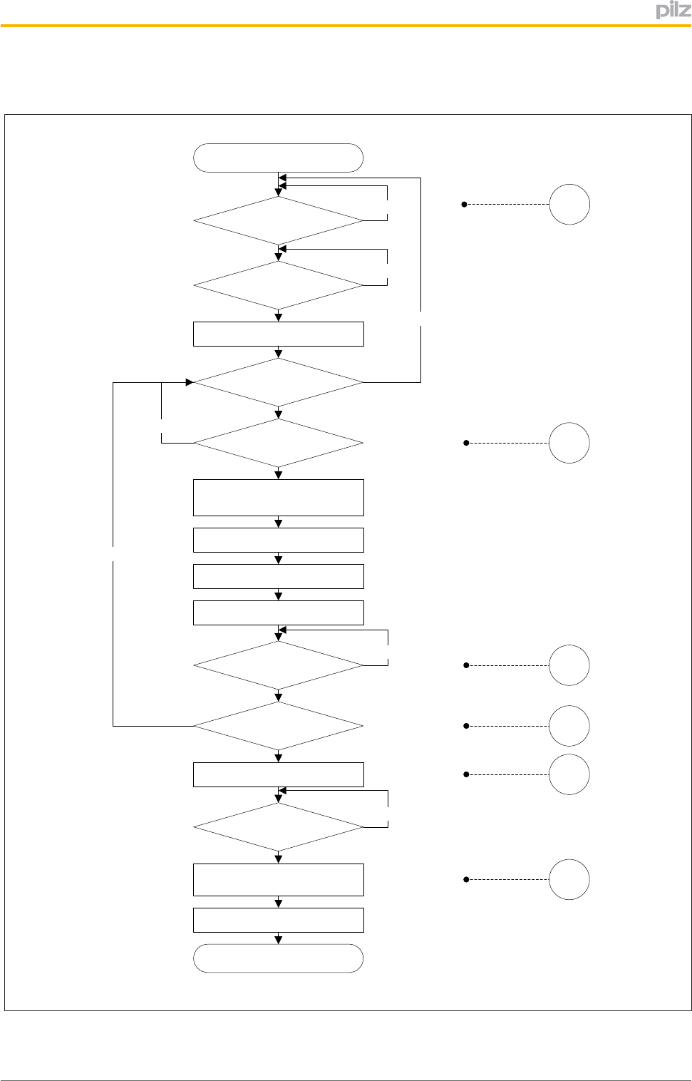
FlowchartforevaluatingtheKeyIDinterface
<IDsync> = 1
Start
<IDsync> = 0 No
<IDclock> = 1
Read
<IDout0> AND <IDout1>
Increment Bit Counter
Set <IDin0> = <IDout0>
Set <IDin1> = <IDout1>
<IDclock> = 0 No
Bit Counter = 14
End
No
Clear Bit Counter
Last Bit Timer >= 60ms
Start Last Bit Timer
No
[b]
[c]
[d]
[e]
[a]
See Fig. „Timing Diagramm
of sender controlled signal
transfer“
<IDsync> = 1
Store ID-Number
Clear
<IDin0> AND <IDin1>
[f]
No
No
Yes
Fig.:EvaluationoftheKeyIDnumberviaacontrolsystem(principle)
Functiondescription
OperatingManualPITm2.1pDMG
1003182EN02 31
4.3.3.2 EvaluationoftheKeyIDnumberwithhandshakecontrolledcommunication
IDo0
(IDsync)
Bit 27
Bit 25 … Bit 02 Bit 01
Bit 00
IDo2
(IDdata)
Bit 26
tV
[b]
[c]
[d]
[f]
th
ten
IDo1
(IDresponse)
IDi0
(IDrequest)
[e][a]
ta
tIDend
200 ms [g]
Fig.:Timingdiagramforhandshakecontrolledsignaldownload
Legend:
Theadditionalterminaldesignations(IDsync,IDresponse,IDdataandIDrequestetc.)are
abbreviationsfortheterminalsignal'sapplication.
IDo0 Controlline
Thesignalisgeneratedbytheoperatingmodeselectorswitch.
"0"signal Notransponderkeyisconnectedorthetransponderkeythatiscon
nectedisinvalid.ThecontrolsystemcannotrequesttheKeyID
number.
"1"signal Avalidtransponderkeyisconnectedandthecontrolsystemcanre
questtheKeyIDnumber.
IDo1 Handshakeline(Response)
Thesignalisgeneratedbytheoperatingmodeselectorswitchandindicates
whetheradatabitatIDo2isvalid/invalid.
"0"signal ThedatabitatIDo2isinvalidandmaynotbeevaluated.
"1"signal ThedatabitatIDo2isvalidandmaybeevaluated.
IDo2 DatalinefordownloadingtheKeyIDnumber
TheKeyIDnumber(28Bit)isgeneratedbytheoperatingmodeselectorswitch.
ThedownloadbeginswithMSB(Bit27…Bit00).
IDi0 Handshakeline(Request)
Thesignalisgeneratedbythecontrolsystem.
"0"signal NobitisrequestedatIDo2
"1"signal AnewbitisrequestedatIDo2.
ten IDsyncEnableTime(min.0ms)
tvDataOutputValidTime(max.10ms)
thDataOutputHoldTime(min.0ms)
taDataOutputAccessTime(max.10ms)

Functiondescription
OperatingManualPITm2.1pDMG
1003182EN02 32
tIDend EndofKeyIDNumberTransfer(200ms)
AfterthelastfallingedgeatIDi0,theoperatingmodeselectorswitchstillhasa
"1"signalatoutputIDo1for200ms.Inthisway,theendoftheKeyIDnumber
andthereforetheendofthedownload(EndofKeyIDNumberTransfer)isdis
played.Thiscanbeusedforthefeasibilitycheck.
Downloadprocedure
[a] "1"signalatIDo0(controlline):
Avalidtransponderkeyispresentattheoperatingmodeselectorswitch.
[b] "1"signalatIDi0(handshakeline):
ThecontrolsystemrequestsadatabitatdatalineIDo2an(=Request).
[c] "1"signalatIDo1(handshakeline):
Theoperatingmodeselectorswitchconfirmsthevalidityofthedatabitatdata
lineIDo2(=Response).
[d] "0"signalatIDi0(handshakeline):
Thecontrolsystemconfirmsthatithasreadtherequesteddatabitwithouterror.
[e] "0"signalatIDo1(handshakeline):
Theoperatingmodeselectorswitchisreadytoissueanewdatabitatdataline
IDo2.
[f] "0"signalatIDo0(controlline):
Thetransponderkeyhasbeenremoved.
[g] ThecontrolsystemmustrequestallthedatabitsofaKeyIDnumber(Bit27…
Bit00).OnlythenisitpossibletostartdownloadinganewKeyIDnumber.The
endofthedownloadisindicatedbythesignalextension(tIDend)atIDo1.
Functiondescription
OperatingManualPITm2.1pDMG
1003182EN02 33
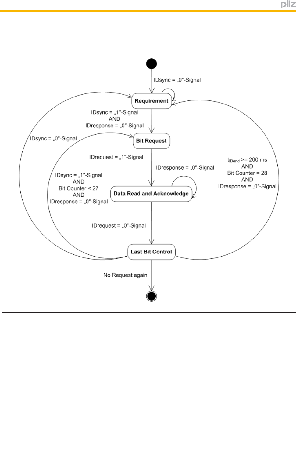
Statusdiagramforhandshakecontrolledsignaldownload
Fig.:Statusdiagramforhandshakecontrolledsignaldownload
Functiondescription
OperatingManualPITm2.1pDMG
1003182EN02 34
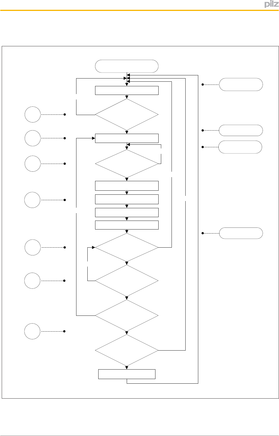
FlowchartforevaluatingtheKeyIDinterface
<IDsync> = 1
AND
<IDresponse> = 0
Increment Bit Counter
Set <IDrequest> = 0
Read Bit <IDdata>
Start Timer
Set <IDrequest>= 1
Set Bit Counter = 0
Store ID Number
<IDresponse> = 1
No
<IDresponse> = 0
Time Control
<tIDend> >= 200ms
No
Bit Counter = 28
Start
[a]
[b]
[c]
[d]
[e]
Last Bit Control
Data Read and
Acknowledge
Bit Request
Requirement
See Fig. „Timing diagram
of handshake controlled
signal transfer“:
See Fig. „State diagram
of handshake controlled
signal transfer“:
<IDsync> = 0
[g]
No
Yes
No
No
[f]
Fig.:EvaluationoftheKeyIDnumberviaacontrolsystem(principle)

Installation
OperatingManualPITm2.1pDMG
1003182EN02 35
5 Installation
5.1 Generalinstallationguidelines
NOTICE
Pleasenotethattheoperatingmodeselectorswitchmayonlybeinstalledin
acustomfitconsolewithaprotectiontypeofatleastIP54!
}TheinstallationsitemustconformtotheprotectiontypeIP54.
}Ensurethattheoperatingmodeselectorswitchhassufficientventilation.
}Attachtheoperatingmodeselectorswitchusingthebracketsprovided.
}Makesurethatthegasketisseatedcorrectly.
Installation
OperatingManualPITm2.1pDMG
1003182EN02 36
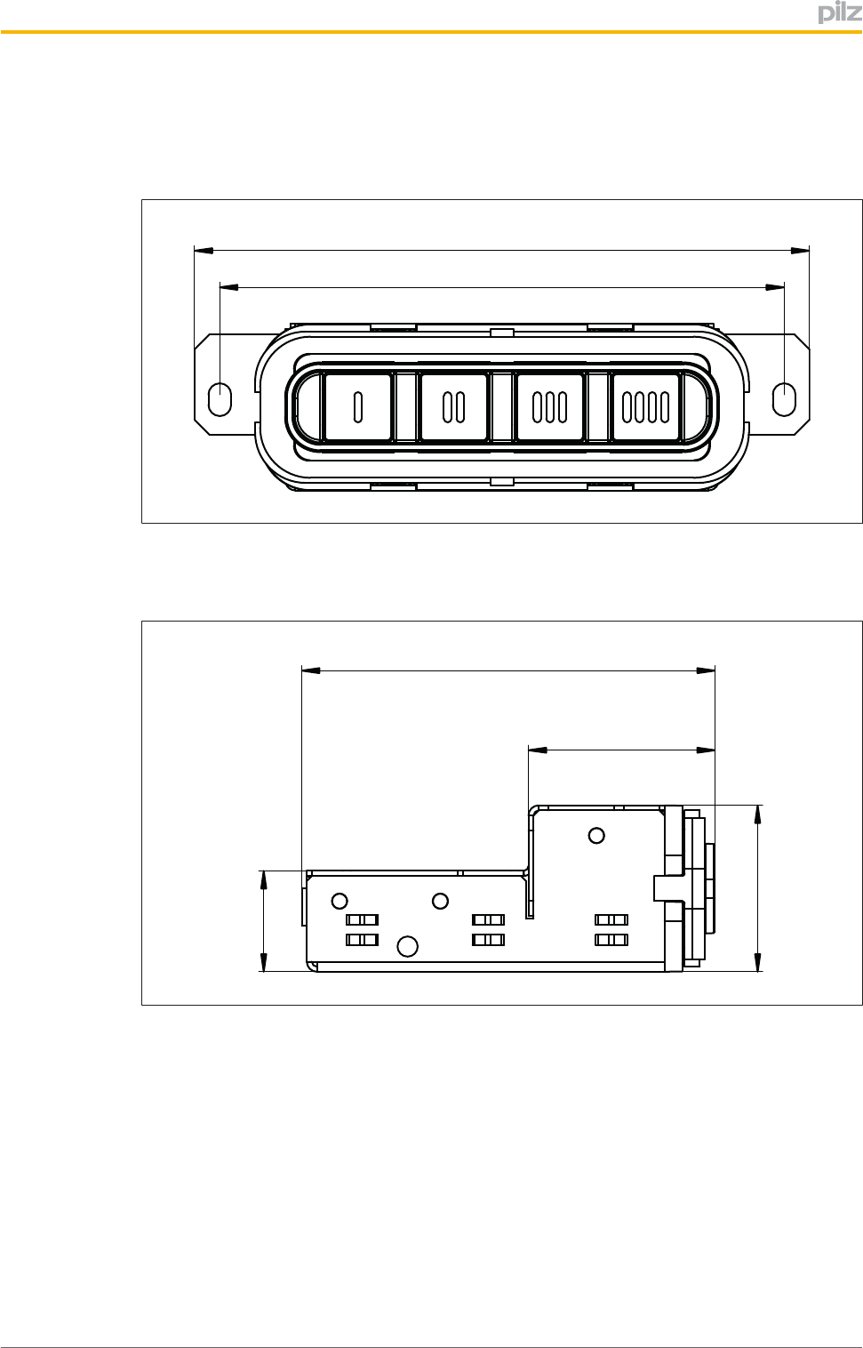
5.2 Dimensions
Frontview
112
122
Sideview
82
20
33
37
Wiring
OperatingManualPITm2.1pDMG
1003182EN02 37
6 Wiring
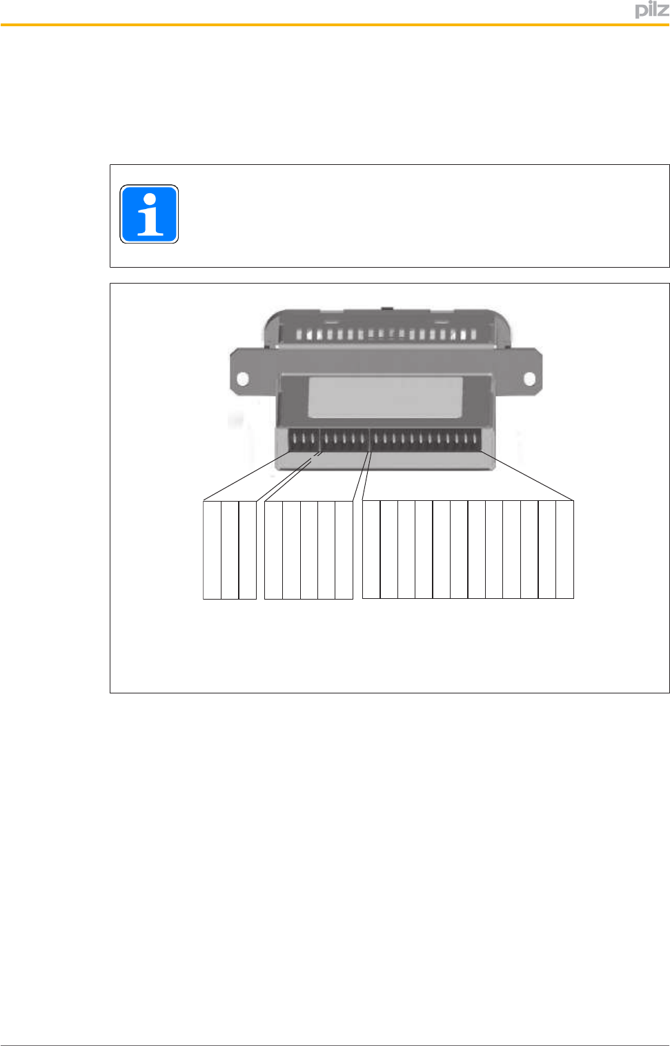
6.1 Terminalconfiguration
INFORMATION
Theconnectionterminalsarenotsuppliedwiththeunit.
X1
1 1 5 1 12
Antenna + 1
Antenna - 2
n.c. 3
SOM1 1
SOM2 2
SOM3 3
3
SOM4 4
SOM5 5
IDo0 1
IDo1 2
IDo2 3
IDo3 4
IDi0 5
IDi1 6
SIo0 7
SIo1 8
SIo2 9
SIo3 10
A1 11
A2 12
X2 X3
+ 24 V DC
0 V
Fig.:Terminalconfiguration
Legend
Antenna+,
Antenna
Terminalsforconnectingtheantenna
n.c. Notconnected
SOM1..SOM5 Operatingmodeinterface:Monitoredsemiconductoroutputsforoperat
ingmodesOM1…OM5
IDo0…IDo3 KeyIDinterface:Semiconductoroutputsforsendingtheoutputsignals
tothecontrolsystem
Thefunctionoftheterminalsdependsonthecommunicationmodethat
hasbeenconfigured.
IDi0…IDi1 KeyIDinterface:Inputstoreceivetheinputsignalsfromthecontrolsys
tem
Thefunctionoftheterminalsdependsonthecommunicationmodethat
hasbeenconfigured.
SIo0…SIo3 InterfaceforstatusinformationEvaluationofstatusinformation
A1,A2 Terminalsforconnectingthesupplyvoltage

Wiring
OperatingManualPITm2.1pDMG
1003182EN02 38
6.2 Connectingtheunit
Proceedasfollows:
1. Connectingthesupplyvoltage
aConnectthesupplyvoltageto(A1,A2).
Pleasenotethefollowing:
Thepowersupplymustmeettheregulationsforextralowvoltageswithprotective
separation(SELV,PELV).
Thecablesfortheunit'ssupplyvoltage(A1,A2)mustbefittedwitha4Afuse,
characteristicB/C.
2. Connectingtheoperatingmodeinterface'ssemiconductoroutputs
aConnecttheoperatingmodeinterface'ssemiconductoroutputstoacontrolsystem
thatsupports"1ooN"evaluation.
Youmustreadtheinformationconcerningintendeduse(seeIntended
use[ 10]).
3. Connectingtheinterface'sterminalsforstatusinformation
aConnecttheterminals(SIo0...SIo3)toacontrolsystemthatsupportsevaluationof
thestatusinformation.
4. ConfigurecommunicationmodefordownloadingtheKeyIDnumber
aTodownloadtheKeyIDnumberinhandshakecontrolledcommunicationmode,
connectterminalsIDo3andIDi1oftheKeyIDinterface.
Noconfigurationisrequiredfortransmittercontrolledcommunicationmode.
5. ConnectingtheterminalsoftheKeyIDinterface
aDependingontheselectedcommunicationmode,connecttheterminalsoftheKey
IDinterfacetoacontrolsystemthatsupportsthedownloadoftheKeyIDnumber.
or
aConnectIDo0toacontrolsystem,ifallyouwishtodoinhandshakecontrolled
communicationmodeisevaluatewhetherthetransponderkeyisvalid/invalid.In
thiscaseyouwillonlyuseIDo0asasignaloutput.Theunusedterminalsonthe
KeyIDinterface(IDo1,IDo2andIDi0)mayremainunwired("open").

Wiring
OperatingManualPITm2.1pDMG
1003182EN02 39
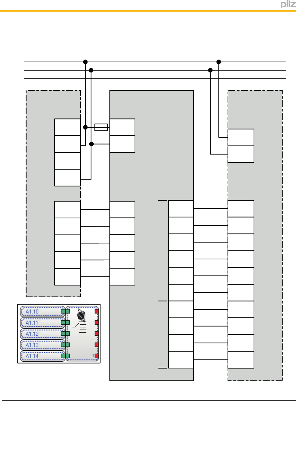
6.3 Connectiontoacontrolsystem
Dependingontheapplicationareaanditsrespectiveregulations,theoperatingmodese
lectorswitchcanbeuseduptoSILCL2(ENIEC62061)anduptoPLd
(ENISO138491),iftheoperatingmodesareevaluatedbyasafetycontrolsystemwith
safe"1oon"evaluation.
Theexamplesbelowmeetthefollowingconditions:
}APNOZm1pisusedasasafetycontrolsystem.
}An"operatingmodeselectorswitch"functionelementisconfiguredinthePNOZmulti
Configuratorforsafe"1oon"evaluation.
}TheKeyIDinterfaceandtheinterfaceforstatusinformationareevaluatedviaahigher
levelprocesscontrolsystem.
}Thecablesfortheunit'ssupplyvoltage(A1,A2)containa4Afuse,characteristicB/C.
Wiring
OperatingManualPITm2.1pDMG
1003182EN02 40
Connectiontoacontrolsystem:Transmittercontrolledcommunicationmode
PIT m2.1p Process Control
System
X3
PNOZ m1p
A1.A1
A1.A1
A1.A2
A1.A2
X7
GND
+24V
X5
A1.I5
A1.I4
A1.I3
A1.I1
Input
SI03
SIo2
SIo1
SIo0
IDi1
IDi0
IDo3
IDo2
IDo1
IDo0
X3
1
L+
A1.I0
2
3
4
5
6
7
8
9
10
PE
Input
Input
Output
Input
Input
Input
Input
PNOZmulti Configurator
Function Element:
Operating Mode Selector Switch
L-
Power Supply
24 V DC
A1
11
A2
12
X2
SOM1
1
SOM2
2
SOM3
3
SOM4
4
SOM5
5
Key ID Interface
Input
Output
(Safe) Operating Modes Interface
Status Information
Interface
F
DMG
Fig.:Connectionfortransmittercontrolledcommunicationmode(example)
Wiring
OperatingManualPITm2.1pDMG
1003182EN02 41
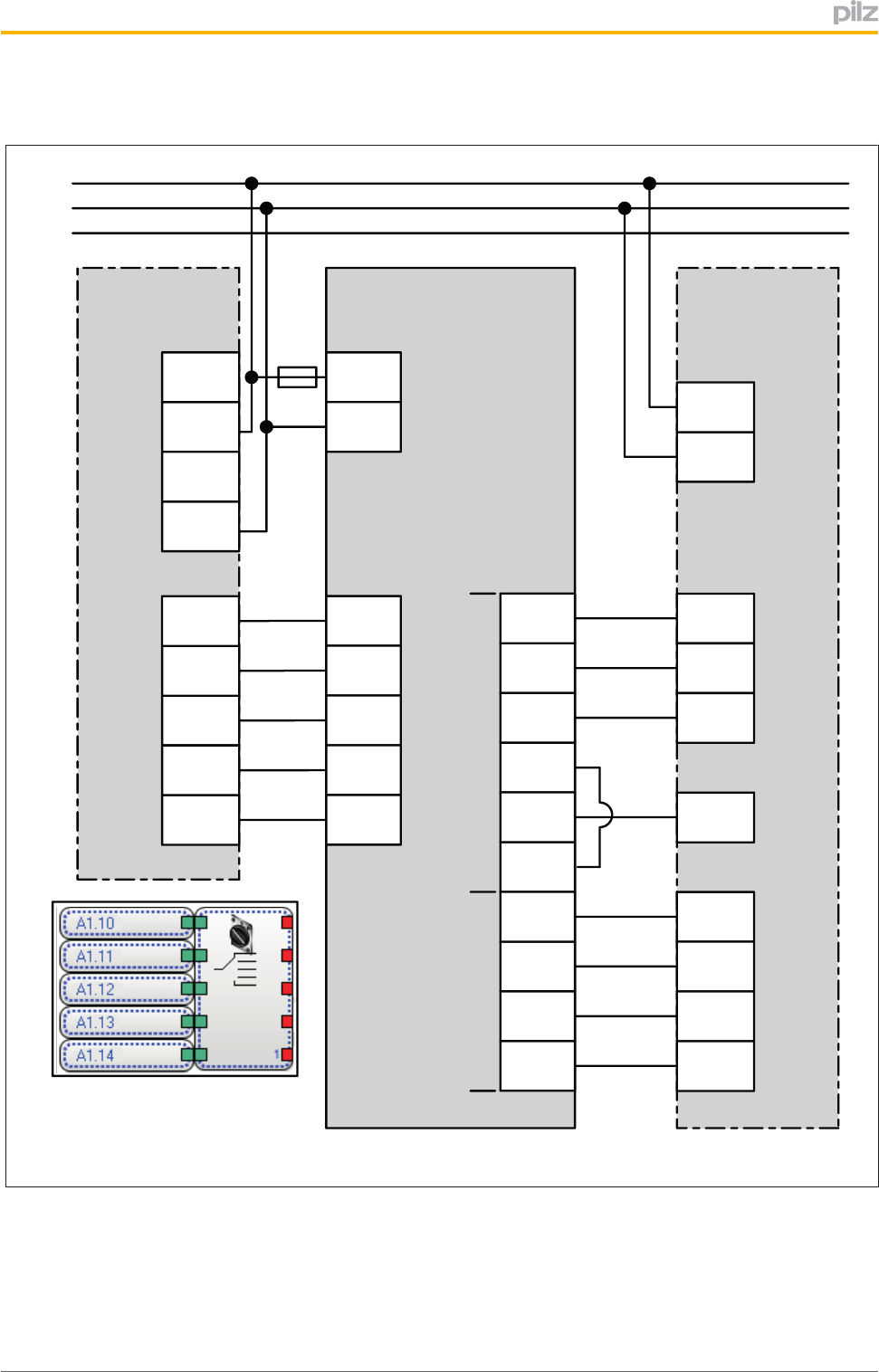
Connectiontoacontrolsystem:Handshakecontrolledcommunicationmode
PIT m2.1p Process Control
System
X3
PNOZ m1p
A1.A1
A1.A1
A1.A2
A1.A2
X7
GND
+24V
X5
A1.I5
A1.I4
A1.I3
A1.I1
Input
SIo3
SIo2
SIo1
SIo0
IDi1
IDi0
IDo3
IDo2
IDo1
IDo0
X3
1
L+
A1.I0
2
3
4
5
6
7
8
9
10
PE
Input
Input
Output
Input
Input
Input
Input
PNOZmulti Configurator
Function Element:
Operating Mode Selector Switch
L-
Power Supply
24 V DC
(Safe) Operating Modes Interface
A1
11
A2
12
X2
SOM1
1
SOM2
2
SOM3
3
SOM4
4
SOM5
5
Key ID Interface
Status Information
Interface
F
DMG
Fig.:Connectionforhandshakecontrolledcommunicationmode(example)

Operation
OperatingManualPITm2.1pDMG
1003182EN02 42
7 Operation
Switchonbehaviour
INFORMATION
Aftertheoperatingmodeselectorswitchisswitchedon(PowerON)orafter
voltageisreturned(reset),operatingmodeOM1isselectedautomatically.
Thisalsoappliesifnotransponderkeyisconnected,oratransponderkeyis
detectedbutisinvalid.
BehaviourintheeventofanerrorinoperatingmodesOM1…OM4
NOTICE
Intheeventofanerror,theunitdoesnotchangeoperatingmode.Theact
iveoperatingmode(OM1,OM2,OM3orOM4)isdisplayedviathebacklit
buttonandtheassignedsemiconductoroutputhasa1signal.
BehaviourintheeventofanerrorinspecialoperatingmodeOM5(Service)
NOTICE
Intheeventofanerror,theunitdoesnotchangeoperatingmode.Faulty
operationisindicatedbythefactthatallbuttonsareeitheralllitorallout.
Theassignedsemiconductoroutputhasa1signal.

Operation
OperatingManualPITm2.1pDMG
1003182EN02 43
7.1 SelectoperatingmodesOM1...OM4
Prerequisites
}Atransponderkeywiththerelevantauthorisationsmustbepresent.
}Theoperatingmodeselectorswitchmustrecognisethetransponderkeyasvalid.
}Thetransponderkeymustbepresentattheoperatingmodeselectorswitchforthe
wholetimethebuttonisoperated.
}Severalbuttonsmaynotbeoperatedsimultaneouslywhenselectinganoperating
mode.
Procedure
1. Establishtransponderkeyconnection
aInsertthetransponderkeyintotheslot
Note:Thetransponderkeymustsupporttheoperatingmode(s)intowhichyouwish
toswitch.
2. Selectoperatingmode
aSelecttheoperatingmodeyouwantbypressingtherelevantpushbutton.
Pleasenotetherequiredoperatingtime(seeMonitoringofoperating
time[ 45]).Theoperatingmodehasbeenselectedcorrectlyifthepushbuttonis
backlitafteritisreleased.
3. Completeoperatingmodeselection
aCompletetheoperatingmodeselectionbyremovingthetransponderkey.
Onceyouhaveremovedthetransponderkey,thelastoperatingmodetobeselec
tedismaintained(seeSwitchbehaviourafteratransponderkeyis
removed[ 22]).
INFORMATION
YoucanswitchatwillbetweentheindividualoperatingmodesOM1,OM2,
OM3andOM4;i.e.itispossibletoswitchfromOM1toOM3orfromOM4to
OM2,forexample.

Operation
OperatingManualPITm2.1pDMG
1003182EN02 44
7.2 SelectspecialmodeOM5(Service)
Prerequisites
}AtransponderkeymustbeavailablewithauthorisationforspecialoperatingmodeOM5
(Service).
}Theoperatingmodeselectorswitchmustrecognisethetransponderkeyasvalid.
}Thetransponderkeymustbepresentattheoperatingmodeselectorswitchforthe
wholetimethebuttonisoperated.
}Severalbuttonsmaynotbeoperatedsimultaneouslywhenselectinganoperating
mode.
Procedure
1. Establishtransponderkeyconnection
aInsertthetransponderkey"KeyService"intotheslot.
2. SelectspecialmodeOM5(Service)
aPresspushbutton1(OM1).
Pleasenotetherequiredoperatingtime(seeMonitoringofoperating
time[ 45]).Theoperatingmodehasbeenselectedcorrectlyifall4pushbuttons
flashwhenpushbutton1isreleased.Thepushbuttonsflashforaslongasyouare
inspecialmodeOM5(Service).
3. Completeoperatingmodeselection
aCompletetheoperatingmodeselectionbyremovingthetransponderkey.
Onceyouhaveremovedthetransponderkey,theoperatingmodeselectorswitch
changestoOM1(seeSwitchbehaviourafteratransponderkeyis
removed[ 22]).
INFORMATION
SpecialoperatingmodeOM5(Service)canbeselectedfromanyoftheop
eratingmodesOM1...OM4.
Operation
OperatingManualPITm2.1pDMG
1003182EN02 45
7.3 Monitoringofoperatingtime
Achangeofoperatingmodesisonlydetectediftherelevantbuttonhasbeenoperatedfora
definedtimeperiod.
Button'soperatingtime
Pushbut
ton Operatingmode Output Operatingtime
1 OM1 SOM1 >50msand
<5s
2 OM2 SOM2
3 OM3 SOM3
4 OM4 SOM4
1 OM5(Service) SOM5 >5sand
<10s
7.4 Switchoverdelayt1
Onceabuttonhasbeenreleased,theassignedoutputontheoperatingmodeinterface
switchestoa"1"signalaftertheswitchoverdelayt1haselapsed(seeTechnical
details[ 48]).Thisdefinedswitchoverdelayguaranteesthatonlyoneoperatingmode
atatimehasa"1"signalattheassignedoutput.
SOM1
SOM2
SOM3
SOM4
SOM5
t1 t1
Fig.:Timebehaviourwhenswitchingoperatingmode

Operation
OperatingManualPITm2.1pDMG
1003182EN02 46
7.5 Troubleshooting
Ifanerroroccursontheoperatingmodeselectorswitch,thelastoperatingmodetobeset
willberetained.
Error Possiblecause Remedy
Unabletoswitchthe
operatingmode
Multipleoperationofbut
tons
Makesurethatonlyonebuttonis
operated
Operatingtimetoolongor
tooshort
Makesurethattheperiodofopera
tionisobserved.
Transponderkeyisnotde
tected
Makesurethatthetransponderkey
isconnectedtotheoperatingmode
selectorswitchorinsertedcorrectly.
Novalidauthorisation Makesurethatyouuseatranspon
derkeythathastherequiredau
thorisation
Operation
OperatingManualPITm2.1pDMG
1003182EN02 47
7.6 Diagnostics
Theoperatingmodeselectorswitchhasvariousoptionsfordisplayingstatusinformation:
}Interfaceforstatusinformation(SIo0…SIo3)
}Buttonbacklighting
7.6.1 Statusinformationabouttheinterfaceforstatusinformation
Variousstatusinformationcanbesignalledviatheinterfaceforstatusinformation(see
Blockdiagram[ 12]).Thestatusinformationcanbeevaluatedthroughacontrolsystem
(seeInterfaceforstatusinformation[ 14]).
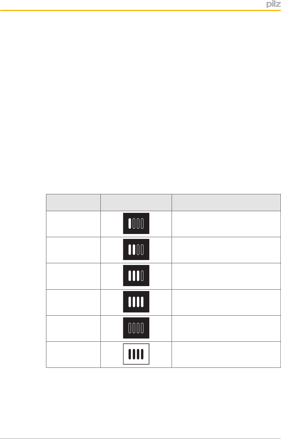
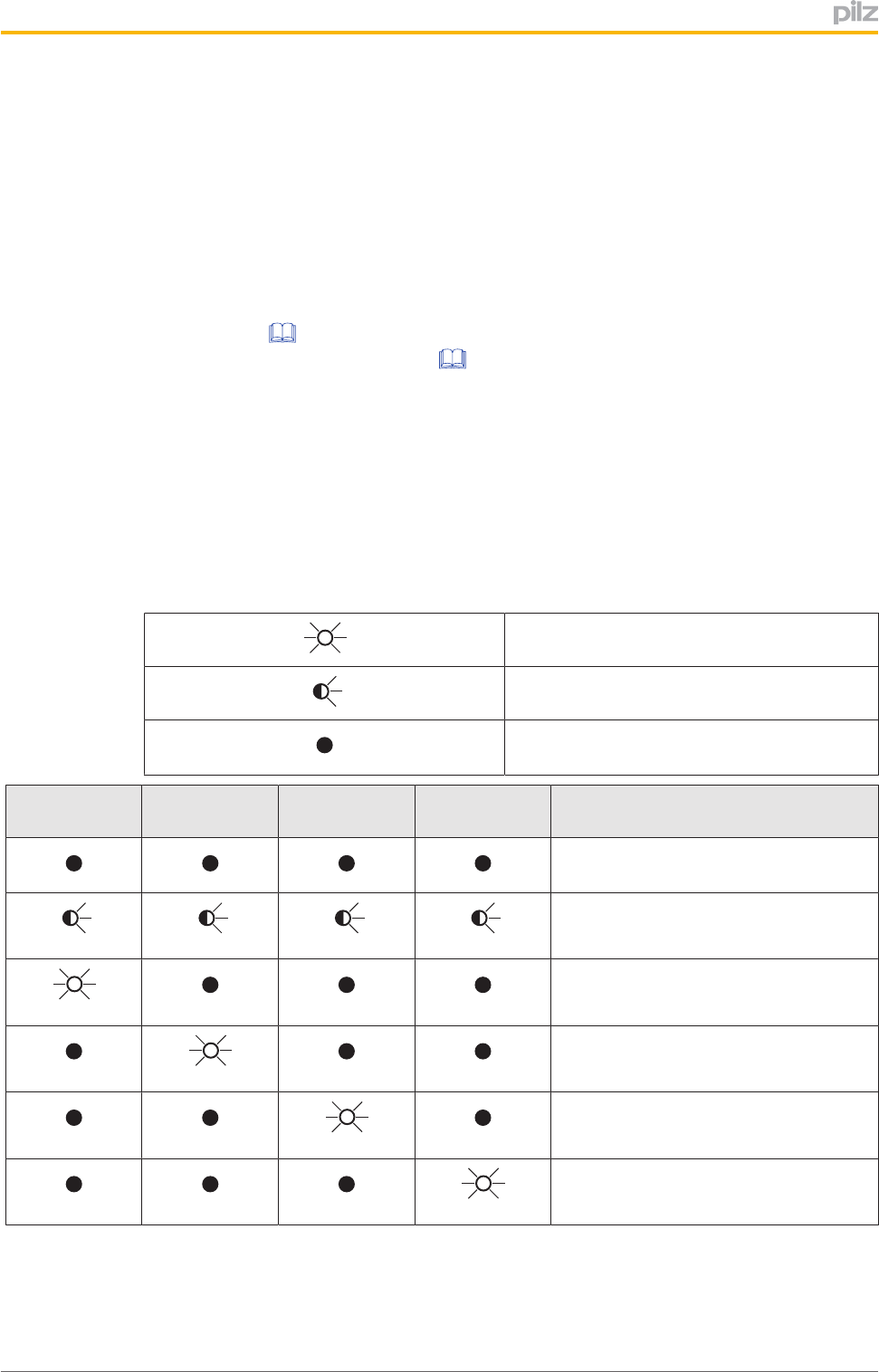
7.6.2 Statusinformationaboutpushbuttonbacklighting
Pushbuttons1…4(seeControlelements)havepushbuttonbacklighting.Pushbuttonback
lightingisusedtoindicatewhichoperatingmodeisactive;inotherwords,whichoutput
(SOM1...SOM5)hasa"1"signal.
Evaluationofpushbuttonbacklighting
Legend:
LEDon
LEDflashes
LEDoff
LEDpushbut
ton1
LEDpushbut
ton2
LEDpushbut
ton3
LEDpushbut
ton4 Meaning
}Nosupplyvoltage
}OM5(Service)isactive
}SOM1hasa"1"signal
}OM1isactive
}SOM1hasa"1"signal
}OM2isactive
}SOM2hasa"1"signal
}OM3isactive
}SOM3hasa"1"signal
}OM4isactive
}SOM4hasa"1"signal

Technicaldetails
OperatingManualPITm2.1pDMG
1003182EN02 48
8 Technicaldetails
General
Approvals CE,FCC,IC,TÜV,cULusListed
Sensor'smodeofoperation Transponder
Transponderinterface
Energysupplytotransponder passive(batteryfree)
Operatingfrequency 125kHz
Electricaldata
Supplyvoltage
Voltage 24,0V
Kind DC
Voltagetolerance 15%/+10%
Outputofexternalpowersupply(DC) 1,0W
ResidualrippleDC 20%
Continuousduty 100%
Statusindicator LED
Inputs
Number 2
Signallevelat"0" 3+5VDC
Signallevelat"1" 1530VDC
Voltageatinputs 24VDC
Inputcurrentrange 2,0mA
Galvanicisolation No
Semiconductoroutputs
Overallperformanceext.loading,semiconductor 3,5W
Numberofpositiveswitchingsinglepolesemicon
ductoroutputs 13
Switchingcapability
Voltage 24V
Current 20,0mA
Signallevelat"1" UB0,5VDC
Residualcurrentat"0" 0,4mA
Shortcircuitproof Yes
Times
Switchondelay
afterUBisapplied 1,0s
Supplyinterruptionbeforedeenergisation 20ms
Switchoverdelayt1 50ms
Operatingtimepushbutton1...4 50ms...5s
Operatingtime,servicepushbutton 5s...10s
Environmentaldata
Climaticsuitability DINIEC6006823
Ambienttemperature
Temperaturerange 055°C

Technicaldetails
OperatingManualPITm2.1pDMG
1003182EN02 49
Environmentaldata
Storagetemperature
Temperaturerange 2570°C
Climaticsuitability
Inaccordancewiththestandard EN60068278
Humidity 95%r.h.at40°C
EMC EN6094751
Vibration
Inaccordancewiththestandard EN6006826
Frequency 10,055,0Hz
Amplitude 0,35mm
Airgapcreepage
Inaccordancewiththestandard EN606641
Overvoltagecategory II
Pollutiondegree 2
Ratedinsulationvoltage 60V
Ratedimpulsewithstandvoltage 0,80kV
Protectiontype
Mountingarea(e.g.controlcabinet) IP54
Housing IP20
Terminals IP20
Mechanicaldata
Operatingdistances
TypicaloperatingdistanceSo 5,0mm
Max.cablelength 1000m
Material
Bottom ST+10µZn
Front ABS
Fixingscrewstorquesettings 0,30Nm
Connectiontype Springloadedterminal,plugin
Conductorcrosssectionwithspringloadedterminals:
Flexiblewith/withoutcrimpconnector 0,202,50mm²,2412AWG
Springloadedterminals:Terminalpointsperconnec
tion 1
Strippinglength 9mm
Dimensions
Height 33,0mm
Width 117,0mm
Depth 82,0mm
Weight 210g
Wherestandardsareundated,the201002latesteditionsshallapply.

Technicaldetails
OperatingManualPITm2.1pDMG
1003182EN02 50
8.1 Safetycharacteristicdata
Operating
mode
ENISO
138491:
2008
PL
ENISO
138491:
2008
Category
EN62061
SILCL
EN62061
PFHD[1/h]
IEC61511
SIL
IEC61511
PFD
ENISO
138491:
2008
TM[year]
–PLd Cat.3 SILCL2 1,10E08 SIL2 5,28E04 20
Alltheunitsusedwithinasafetyfunctionmustbeconsideredwhencalculatingthesafety
characteristicdata.
INFORMATION
Asafetyfunction'sSIL/PLvaluesarenotidenticaltotheSIL/PLvaluesof
theunitsthatareusedandmaybedifferent.Werecommendthatyouuse
thePAScalsoftwaretooltocalculatethesafetyfunction'sSIL/PLvalues.

Supplementarydata
OperatingManualPITm2.1pDMG
1003182EN02 51
9 Supplementarydata
9.1 Radioapproval
FCC/ICapproval
USA/Canada
FCC ID: VT8-
IC: 7482A-
FCC/IC-Requirements:
This product complies with Part 15 of the FCC Rules and with Industry Canada licence-exempt RSS standards.
Operation is subject to the following two conditions:
1) this product may not cause harmful interference, and
2) this product must accept any interference received, including interference that may cause undesired operation.
Changes or modifications made to this product not expressly approved by Pilz may void the FCC authorization to operate this equipment.
NOTE: This equipment has been tested and found to comply with the limits for a Class A digital device, pursuant to Part 15 of the FCC Rules.
These limits are designed to provide reasonable protection against harmful interference when the equipment is operated in a commercial
environment. This equipment generates, uses, and can radiate radio frequency energy and, if not installed and used in accordance with the
instruction manual, may cause harmful interference to radio communications. Operation of this equipment in a residential area is likely to cause
harmful interference in which case the user will be required to correct the interference at his own expense.
Le présent produit est conforme aux CNR d'Industrie Canada applicables aux appareils radio
exempts de licence. L'exploitation est autorisée aux deux conditions suivantes:
(1) le produit ne doit pas produire de brouillage, et
(2) l'utilisateur de le produit doit accepter tout brouillage radioélectrique subi, même si le brouillage est susceptible d'en compromettre le
fonctionnement.
PITM2
PITM2

Orderreference
OperatingManualPITm2.1pDMG
1003182EN02 52
10 Orderreference
10.1 Product
Type Features Orderno.
PITm2.1pDMG Operatingmodeselectorswitchwithan
tenna
402201
10.2 Accessories
Terminals
Type Features Orderno.
Springloadedterminals 1set 402304
Antenna
Type Features Orderno.
PITm2.1pDMGantenna Antenna 402202
Transponderkey
Type Features Orderno.
PITm2.1keymode1 TransponderKeyMode01 402051
PITm2.1keymode2 TransponderKeyMode02 402052
PITm2.1keymode3 TransponderKeyMode03 402053
PITm2.1keymode4 TransponderKeyMode04 402054
PITm2.1keyservice TransponderKeyService 402055
PITm2.1keymaster TransponderKeyMaster 402056

The Best of
German
En gineering
Partner of:
Support
Technical support is available from Pilz round the clock.
Americas
Brazil
+55 11 97569-2804
Canada
+1 888-315-PILZ (315-7459)
Mexico
+52 55 5572 1300
USA (toll-free)
+1 877-PILZUSA (745-9872)
Asia
China
+86 21 60880878-216
Japan
+81 45 471-2281
South Korea
+82 31 450 0680
Australia
+61 3 95446300
Europe
Austria
+43 1 7986263-0
Belgium, Luxembourg
+32 9 3217575
France
+33 3 88104000
Germany
+49 711 3409-444
Ireland
+353 21 4804983
Italy
+39 0362 1826711
Scandinavia
+45 74436332
Spain
+34 938497433
Switzerland
+41 62 88979-30
The Netherlands
+31 347 320477
Turkey
+90 216 5775552
United Kingdom
+44 1536 462203
You can reach our
international hotline on:
+49 711 3409-444
support@pilz.com
CMSE ®, InduraNET p ®, PAS4000 ®, PAScal ®, PASconfig ®, Pilz ®, PIT ®, PLID ®, PMCprimo ®, PMCprotego ®, PMCtendo ®, PMD ®, PMI ®, PNOZ ®, Primo ®, PSEN ®, PSS ®, PVIS ®, SafetyBUS p ®,
SafetyEYE ®, SafetyNET p ®, the spirit of safety ® are registered and protected trademarks of Pilz GmbH & Co. KG in some countries. We would point out that product features may vary
from the details stated in this document, depending on the status at the time of publication and the scope of the equipment. We accept no responsibility for the validity, accuracy
and entirety of the text and graphics presented in this information. Please contact our Technical Support if you have any questions.
Pilz develops environmentally-friendly products using
ecological materials and energy-saving technologies.
products and environmentally-friendly solutions.
Pilz GmbH & Co. KG
Felix-Wankel-Straße 2
73760 Ostfildern, Germany
Tel.: +49 711 3409-0
Fax: +49 711 3409-133
info@pilz.com
www.pilz.com
100XXXX-DE-0X
0-0-2-3-000, 2014-00 Printed in Germany
© Pilz GmbH & Co. KG, 2014
1003182EN02,201411PrintedinGermany
©PilzGmbH&Co.KG,2011
Backcover