Pilz and KG PSENSLN RFID Proximity switch User Manual PSEN sl 1 0n 1 1 2 1 2 2 mif
Pilz GmbH & Co. KG RFID Proximity switch PSEN sl 1 0n 1 1 2 1 2 2 mif
UserManual.wiki
>
Pilz and KG
>
PSENSLN User Manual
>
manual part1
Contents
1.
manual part1
2.
manual part2
manual part1
Navigation menu
Upload a User Manual
Namespaces
Wiki Guide
HTML
PDF
Info
Views
User Manual
Discussion / Help
Navigation
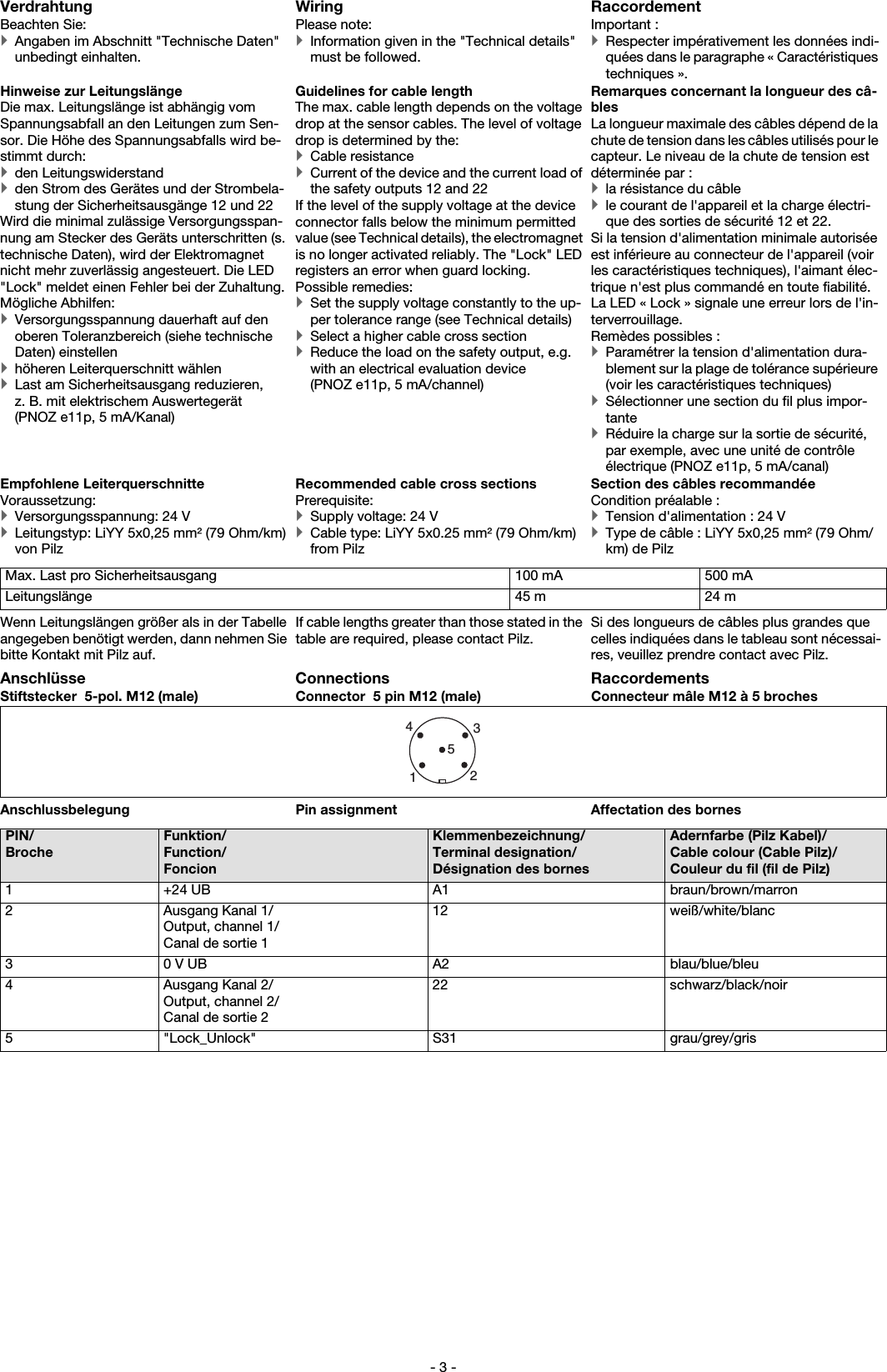
![- 15 -Zugehörige Betätiger Corresponding actuator Actionneurs correspondants PSEN sl-1.0 1.1, PSEN sl-1.0fm 1.1 No. 570603PSEN sl-1.0 2.1, PSEN sl-1.0fm 2.1 No. 570604, 570605Anschlussart Connection type Type de connection M12, 5-pol. Stiftstecker/Con-nector male 5 pin M12/Con-necteur mâle M12 à 5 brochesLeitung Cable Câble LiYY 5 x 0,25 mm2Schutzart Protection type Indice de protection IP67Material Material MatériauGehäuse Housing Boîtier PBTAnkerplatte Anchor plate Plaque de maintien Stahl vernickelt/nickel-platedsteel/acier nickeléBodenplatte Base plate Plaque support Anticorodal, hart eloxiert/Anti-corodal, hard anodised/Anti-corodal, anodisé durBetätiger Actuator Actionneur Anticorodal, hart eloxiert/Anti-corodal, hard anodised/Anti-corodal, anodisé durAbmessungen siehe Abbildung Dimensions, see graphic Dimensions, voir l'illustrationGewicht Weight PoidsSensor Sensor Capteur 1.148 gBetätiger Actuator Actionneur 599 gSicherheitstechnische Kennda-ten Safety-related characteristic data Caractéristiques techniques de sécuritéPL nach EN ISO 13849-1: 2006 PL in accordance with EN ISO 13849-1: 2006 PL selon EN ISO 13849-1: 2006 PL e (Cat. 4)Kategorie nach EN 954-1 Category in accordance with EN 954-1 Catégorie selon EN 954-1 Cat. 4SIL CL nach EN IEC 62061 SIL CL in accordance with EN IEC 62061 SIL CL selon EN IEC 62061 SIL CL 3PFH nach EN IEC 62061 PFH in accordance with EN IEC 62061 PFH selon EN IEC 62061 1,57E-09SIL nach IEC 61511 SIL in accordance with IEC 61511 SIL selon IEC 61511 SIL 3PFD nach IEC 61511 PFD in accordance with IEC 61511 PFD selon IEC 61511 1,38E-04TM [Jahr] nach EN ISO 13849-1: 2006 TM [year] in accordance with EN ISO 13849-1: 2006 TM [année] selon EN ISO 13849-1: 2006 20Es gelten die 2012-09 aktuellen Ausgaben der Normen.The standards current on 2012-09 apply. Les versions actuelles 2012-09 des normes s'appliquent.Bestelldaten Order reference RéférencesTyp/Type/Type Stück/Quantity/NombreWirkweise/Operation/Ac-tionnement Merkmale/Features/ Caractéri-stiques Bestell-Nr./Order no./RéférencePSEN sl-1.0n 1.1 1 Transpondertechnik/Trans-ponder technology Technique à transpondeurSicheres Schutztürsystem, codiert/Safety gate system,coded/ Système de sécurité pour protecteurs mobi-les, codé570 603PSEN sl-1.0n 2.1 1 Transpondertechnik/ Trans-ponder technology Technique à transpondeurSicheres Schutztürsystem, vollco-diert/Safety gate system, fully co-ded/ Système de sécurité pour protecteurs mobiles, précodé570 604PSEN sl-1.0n 2.2 1 Transpondertechnik/ Trans-ponder technology Technique à transpondeurSicheres Schutztürsystem, unikat codiert/Safety gate system, uniquely coded/ Système de sécurité pour protecteurs mobiles, codé unique570 605PSEN sl bracket swing door 1 - Montagewinkel für Schwenk- und Flügeltüren/ Mounting bracket for swing doors570 550PSEN sl bracket sliding door 2 - Montagewinkel für Schiebetüren/ Mounting bracket for swing doors570 551Mechanische Daten Mechanical data Données mécaniques](https://usermanual.wiki/Pilz-and-KG/PSENSLN.manual-part1/User-Guide-3238196-Page-15.png)