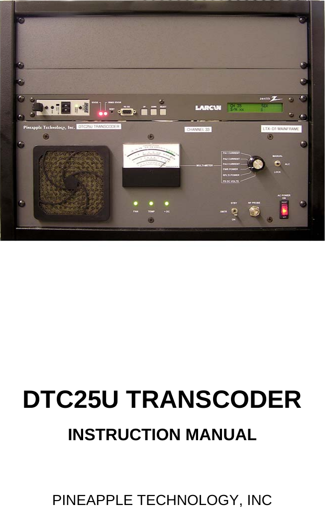
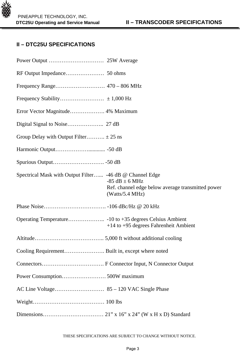
Pineapple Technology DTC25U 25 WATT ATSC TRANSCODER User Manual DTC25U

Pineapple Technology, Inc. 25 WATT ATSC TRANSCODER DTC25U

DTC25U User Manual

DTC25U TRANSCODERINSTRUCTION MANUALPINEAPPLE TECHNOLOGY, INC
PINEAPPLE TECHNOLOGY, INC.  DTC25U  Operating and Service Manual TABLE OF CONTENTSSection l --- SAFETY NOTICES    …………………………………………………………………………2** READ THIS SECTION BEFORE INSTALLATON **Secton ll --- TRANSCODER SPECIFICATIONS   …………………...…………………………………3Section lll --- TRANSCODER INSTALLATION   ……………………………………………………… 4Section lV --- TRANSCODER TURN-ON   ………………………………………………………………5Section V --- THEORY OF OPERATION   A. Introduction   ………………………………………………………………………………8B. XC100LC Regenerative Transcoder Module and Up Converter………………………8C. LTX Mainframe Assembly ……………………………………………………………… 9D. BPUD100 Digital Mask Filter………………………………………………………………9E. Low Pass Filter (Optional)…………………………………………………………………9SECTION Vl --- SCHEMATIC AND PARTS LISTSA. DTC25U………………………………………………………….................................... 10B. LTX Mainframe Assembly…………………………………………………………………12C. BPUD100Digital Mask Filter………………………………………………………………14D. Low Pass Filter…………………………………………………………………………… 15SECTION Vll --- RECOMMENDED ROUTINE MAINTENANCE   ……………………………………16SECTION Vlll --- ADJUSTMENTS AND TUNING   …………………………………………………… 17SECTION lX --- PROBLEM SOLVING / TROUBLESHOOTING   ……………………………………18SECTION X --- WARRANTY   …………………………………………………………………………… 20
Section ISafetyNotices
PINEAPPLE TECHNOLOGY, INC.  DTC25U  Operating and Service Manual l --- SAFETY NOTICESl ---SAFETY NOTICES** READ THIS SECTION BEFORE INSTALLATION **SEVERE ELECTRICAL SHOCK OR BURNS MAY OCCUR      IF THIS EQUIPMENT IS USED IMPROPERLY.NEVER WORK ON THIS EQUIPMENT ALONE. ALWAYS HAVE ANOTHER PERSON PRESENTWHILE WORKING ON ELECTRICAL CIRCUITS OR MOVING EQUIPMENT. COMMUNICATIONS                  TO EMERGENCY SERVICES SHOULD BE AVAILABLE AT ALL TIMES.   BEFORE CONNECTING THIS EQUIPMENT TO ANY AC ELECTRICAL SOURCE READ THE  SECTION ON INSTALLATION. ALL ELECTRICAL WIRING FOR THIS EQUIPMENT MUST BE    PERFORMED BY QUALIFIED ELECTRICIANS. ALL WIRING MUST BE COMPLIANT WITH                                                 LOCAL ELECTRICAL CODES.POWER AMPLIFIERS AND SUPPLIES ARE HEAVY. TO INSTALL THIS EQUIPMENT IN RACKS                         USE TWO (2) PERSONS TO AVOID POSSIBLE INJURIES.NEVER OPEN THE CABINET ENCLOSURE OR UNPLUG CABLES OR WIRES WHILE THIS                                             EQUIPMENT IS OPERATING.       ALL SERVICE WORK MUST BE PERFORMED BY QUALIFIED TECHNICIANS ONLY.   IF ONE IS NOT AVAILABLE LOCALLY, CONTACT PINEAPPLE TECHNOLOGY, INC. FOR                                                  A LIST IN YOUR AREA.               Page 2
Section IITransmitterSpecifications
THESE SPECIFICATIONS ARE SUBJECT TO CHANGE WITHOUT NOTICE.          PINEAPPLE TECHNOLOGY, INC.               DTC25U Operating and Service Manual                II – TRANSCODER SPECIFICATIONS    II – DTC25U SPECIFICATIONS   Power Output …………………………  25W Average                    RF Output Impedance…………………  50 ohms  Frequency Range……………………… 470 – 806 MHz  Frequency Stability……………………  ± 1,000 Hz  Error Vector Magnitude………………. 4% Maximum  Digital Signal to Noise………………..  27 dB  Group Delay with Output Filter………. ± 25 ns  Harmonic Output………………............ -50 dB  Spurious Output………………………. -50 dB  Spectrical Mask with Output Filter…...  -46 dB @ Channel Edge      -85 dB ± 6 MHz           Ref. channel edge below average transmitted power      (Watts/5.4 MHz)  Phase Noise……………………………. -106 dBc/Hz @ 20 kHz   Operating Temperature………………..  -10 to +35 degrees Celsius Ambient      +14 to +95 degrees Fahrenheit Ambient  Altitude……………………………….. 5,000 ft without additional cooling  Cooling Requirement…………………. Built in, except where noted  Connectors……………………………. F Connector Input, N Connector Output  Power Consumption…………………… 500W maximum  AC Line Voltage………………………  85 – 120 VAC Single Phase  Weight………………………………… 100 lbs  Dimensions…………………………… 21” x 16” x 24” (W x H x D) Standard               Page 3
Section IIITransmitterInstallation
PINEAPPLE TECHNOLOGY, INC.  DTC25U  Operating and Service Manual lll -- TRANSCODER INSTALLATIONlll -- TRANSCODER INSTALLATIONTo ensure long and reliable trouble-free service from the DTC25U transcoder the following stepsfor installation are recommended:1. MECHANICAL INSTALLATION: The DTC25U Transcoder was designed to be installed in a buildingprotected from the weather. The building should have a hard-surface floor such as concrete with a moisture barrier. This barrier could be pressure-treated wood sub flooring which could be anchoredto the concrete and to the transmitter to make the installation earthquake resistant.Allow a minimum of three feet around the transmitter cabinet for service access. The top of thetransmitter should be clear for three feet above to allow the air to exhaust from the transmitter.Provisions for air inlet and exhaust from the room must allow air flow with minimal obstruction.In the event that the room temperature exceeds 35º Celsius (95º F), cooling air must be providedso that the room temperature will not exceed 35 degrees Celsius under worse case conditions.Notice: This equipment is HEAVYand must be handled by professional movers with properequipment. Any damage caused by the installers is not covered under warranty. Check to ensurethat installing crews have proper insurance coverage.2. GROUNDING: Transmitter grounding is VERY IMPORTANT and must be done correctly forsafety and operational reasons. A typical installation may be done as follows:Use a heavy gauge wire such as 16 AWG stranded copper. The bonding between the transmitter and the ground rods must be good quality and protected from corrosion. The ground wires should run over the floor and be connected to the ground rods located outside the building. The wire should not go thru the concrete floor but over and around it.3. AC WIRING: The DTC25U transcoder comes with a three wire 110 VAC standard plug for connection to a 110 VAC electrical outlet. It is recommended that the electrical outlet be protected with its own separate breaker and used only for the transcoder.NOTICE: All wiring of this type, except for the actual connection to the AC plug,  must be done by a QUALIFIED ELECTRICIAN and must conform to LOCAL and NATIONAL wiring CODES.Consult with your electrician to ensure that the proper breaker size is selected for the main circuit.4. ANTENNA CONNECTION: The transcoder is equipped with an N connector for output power to the transmit antenna and an F connector for connection from the receive antenna.               Page 4
Section IVTransmitterTurn-On
PINEAPPLE TECHNOLOGY, INC.  DTC25U  Operating and Service Manual lV -- TRANSCODER TURN-ON PROCEDURElV --- TRANSCODER TURN-ON PROCEDURE (Page 1 of 3)See the previous section on installation before proceeding with this section. Improper installation of thetranscoder can cause serious damage to the equipment or operating personnel and may voidmanufacturers warranty. Initial turn on and check out is very important for the broadcast engineer tolearn how to setup and operate the transcoder. Following these steps will ensure long and reliable operation:1. Check the transcoder output load or antenna for proper installation and connection to the transcoder.2. Inspect the transcoder front and back to check for broken items or lose fitting items. These mustbe replaced or properly secured before turning the transcoder on. Pay special attention to all RFconnectors including transmit coaxial cable and antenna. 3. Check the AC breaker and on/off switches to ensure that all are in the OFF position.4. Verify the switch on the power strip at the back of the cabinet and the power switch on the front of the LTX Mainframe are in the OFF position. Plug in the AC power cord to a nearby 110 AC electricalconnector with associated, appropriately sized, circuit breaker.5. Verify the output power level on the Drake Upconverter is set to minimum ( GAIN fully CCW ). See Fig 1 below for location.  On the LTX Mainframe verify XMTR switch is in STBY.6. Refer to the transcoder and upconverter instruction manuals in the DTC25U User Manual to locate the key functions and become familiar with the unit. Insure that all connections, including the DC power connection and the RF (IF) connection, between the 8VSB Regenerator and Upconverter have been made. 7. Verify, using the front panel display on the transcoder upconverter, that the correct output channel has been selected. At this time, no connection should be made to the transcoder input at the back of the unit. Any following measurements will be done using the Null Packets generated inside the transcoder.8. Turn-on the switch located on the power strip at the rear of the DTC25U. Note: The Larcan Transcoder will come on at this time as well as the cabinet fan. A green light indication should be seen on the Drake Upconverter and, after a few minutes, the two green lights on the transcoder will turn red indicating proper operation.9. Locate and turn on the front panel breaker found on the LTX Mainframe and set the XMTR switch to the ON position. MAKE THE FOLLOWING OBSERVATIONSMETER READINGS TYPICALDC SUPPLY VOLTAGE32 VDCPA1 DRIVER CURRENT1.7 AMPS ± 20%PA2 FINAL CURRENT2.7 AMPS ± 20%PA3 FINAL CURRENT1.3 AMPS ± 20%RF OUTPUT POWER 10 TO 50%RFL'D POWER < 10%NOTE STATUS LIGHTSFAN GREENTEMP GREEN+DC GREENTHE FAN SHOULD BE MAKING SOME NOISE              Page 5
PINEAPPLE TECHNOLOGY, INC.  DTC25U  Operating and Service Manual lV -- TRANSCODER TURN-ON PROCEDURElV --- TRANSCODER TURN-ON PROCEDURE (Page 2 of 3)Note: Allow the DTC25U to warm up for at least one (1) hour before making the final adjustment.If transmitter is not warmed up, the output power will require re-adjustment to proper level when it is warm.10. Select the FWD Power setting on the rotary switch associated with the front panel meter on the LTX Mainframe assembly. Slowly adjust the power level setting on the Drake Upconverter while observing the output power level on the front panel meter until the meter reading indicates 100% output power.RECORD AND RETAIN THE FOLLOWING OBSERVATIONS FOR FUTURE REVIEW IF NECESSARY.METER READINGS TYPICALDC SUPPLY VOLTAGE 32 VDCPA1 DRIVER CURRENT 1.8 AMPS ± 20%PA2 FINAL CURRENT 3.4 AMPS ± 20%PA3 FINAL CURRENT 2.8 AMPS ± 20%RF OUTPUT POWER 90 TO 100%RFL'D POWER < 10%NOTE STATUS LIGHTSFAN GREENTEMP GREEN+DC GREENFIG. 1              Page 6
PINEAPPLE TECHNOLOGY, INC.  DTC25U  Operating and Service Manual lV -- TRANSCODER TURN-ON PROCEDURElV --- TRANSCODER TURN-ON PROCEDURE (Page 3 of 3)11. The receive signal antenna can now be connected to the input of the transcoder as required. Note: The receive antenna should be located so that it will not pick up the transmitter outputsignal. Even when the input and output channel separation may seem to be considerable,the input receiver front end can be over loaded. This will reduce the sensitivity of thereceiver resulting in degraded or loss of signal when viewed at the DTC25U transmit out.                Page 7
Section VTheoryofOperation
PINEAPPLE TECHNOLOGY, INC.  UTX1K ULTRA  Operating and Service Manual                   V -- THEORY OF OPERATIONV --- THEORY OF OPERATION  (Page 1 of 2)A. INTRODUCTIONThe DTC25U transcoder was designed to meet or exceed all FCC applicable specifications forTV broadcast equipment. Special attention was given to the selection of sub-assemblies and componentsto achieve maximum reliability and minimum down time. The construction of the DTC25U isBASIC and MODULAR with most components field replaceable. Special emphasis was placed on"KEEPING IT SIMPLE" and returning to more traditional transmitter layouts and instrumentation.Refer to the DTC25U block diagram for an overview of the transmitter architecture. This will give the technician basic information needed to understand the operation of the transmitter and the function of each subassembly.SEE SECTION Vl.A  FOR PARTS LIST AND BLOCK DIAGRAM.B.  XC100LC Regenerative TranscoderB-1 ExciterRefer to the Larcan user manual for information on the exciter portion of the transcoder.SEE SECTION VI.B FOR SCHEMATIC AND PARTS LISTB-2. Drake Up ConverterRefer to Drake user manual for information on the operation of this portion of the transcoder.              Page 8
PINEAPPLE TECHNOLOGY, INC.  DTC25U  Operating and Service Manual                   V -- THEORY OF OPERATIONV. THEORY OF OPERATION (CONTINUED)  (Page 2 of 2)C. LTX Mainframe Power AmplifierCabinet - The cabinet is constructed of heavy gauge steel and is very durable. This enclosure is painted black and is resistive to harsh environment. Standard 19 inch rack mounting. LTX-D1 Mainframe Assembly -  Internal sub-assemblies include the following:1. DC Power Supply2. RF Deck3. Status Monitoring (1A0035)4. Output Power Detector Board (1A0027)5. Reflected Power Detector (1A0029) and Shutdown Switch6. Metering and Monitoring Assembly (1A0300)For details of this sections above, see appropriate sections in this manual.D. BPUD100 Digital Mask FilterThe FCC Stringent Mask filter supplied with the DTC25U transcoder is designed to completely satisfy the FCC Rules for a low power TV transmitter and translator.This is a closed unit and does not require field adjustment. E. Optional Low Pass FilterThis low pass filter is required and will be supplied with DTC25U translators that operate on Channels 22 - 24, 32 - 36 and 38 for the specific purpose of providing "out of band" protection to Radio Navigation Satellite Services.              Page 9
Section VISchematicandParts List
PINEAPPLE TECHNOLOGY, INC.  DTC25U  Operating and Service ManualVl -- SCHEMATICS AND PARTS LISTA. DTC25U Assembly TreeItem Qty Type P/N Title DetailTop CAT DTC25U UHF TV TRANSCODER 25 W RMLARCAN EXCITTER/CONVERTER1 1 PS BPUD100 DIGITAL MASK FILTER UHF TV 100 WATTS RMS2 1 PL LTXMAINFRAME LTX SERIES XMTR 100 W UHF  BASIC UNIT3 1 PS XC100LC TRANSCODER, LARCAN UHF DIGITAL TRANSLATOR              Page 10
SIZE FSCM NO.SCALE SHEETDWG NO. REVPineapple Technology, Inc.Rocklin, CAMaskFilterAC Inlet AC InletDC InletRF Input RF InputRF Output Mon RF ProbeRemoteInterfaceDC OutLarcan8VSB RegenTranscoderDrakeDCU860Up ConvLTX-D1MainframeAssemblyAntRF InOptionalLow PassFilteras requiredIFDTC25UDigital TranscoderAB11:1XC100LCDB9              Page 11
PINEAPPLE TECHNOLOGY, INC.  DTC25U  Operating and Service ManualVl -- SCHEMATICS AND PARTS LISTB. LTX-D1 Mainframe Assembly TreeItemQtyType P/N Title DetailTop PL LTXMAINFRAMLTX SERIES XMTR 100 W UHF  BASIC UNIT1 1 PS MF9529A LTX HEAT SINK HOLDER AL 0902 1 PS MF9531A LTX FRONT PANEL 0125 AL W/PAINT AND SILK3 1 PS MF9532A LTX CHASSIS 090 AL ALODYNE W/REAR SILK4 1 PS MF9533A LTX AIR DAM DEFLECTOR 050 AL ALODYNE5 1 PS MF9534A LTX TOP COVER O60 AL ALODYNE6 1 PL MF9535 LTX100U HEAT SINK STD HEAT SINK W/U250LD FP7 0 PS MF9536 LTX100 VHF HIGH HEAT SINK STD PTI HS MATERIAL8 0 PS MF9537 LTX100 VHF LOW BAND HEAT SINK STD PTI HS MATERIAL9 0 PS MF9538  LTX200U HEAT SINK U250LD MTG WITH DRIVER10 1 PS PC9515 COUPLER GP COVER TMM3 0125 USE ON ALL -30dB COUPLERS11 1 PS PC9514 UHF -30 dB COUPLER TMM3 0125 DUAL DIRECTIONAL12 0 PS PC9513 VHF HB -30 dB COUPLER TMM3015 DUAL DIRECTIONAL13 0 PS PC9512 VHF LB -30 dB COUPLER TMM30125 DUAL DIRECTIONAL14 1 PS 660104 LTX MULTI-FUNCTION METER HOYT MODEL 3135 ANALOG MTR15 1 PS AC3108 CIRCUIT BREAK/ ON/OFF SWITCH 115 VAC 10 A RESETABLE16 1 PS AC1003 FILTER, AC LINE 110/220 AC PLUG17 1 PS 990200 FILTER, AIR DRY COMAIR FILTER/GUARD ASS,Y18 1 PS 851035 FAN AC 115 100 CFM 115 VAC COMAIR-ROTRON MUFFIN XL AC MX2A319 1 PS CA5110 CABLE ASSEMBLY 10 WIRE 10 WIRE SOC TO SOC CONNECTOR20 4 PS 480300 CON 2 PIN HEADER AMP A23837-ND22 1 PS AC2010 DC POWER SUPPLY 115/220 VAC 320 WATTS 27-31 VDC23 6 PS INHOUSE_LABPTI LABOR  LOADED24 8 PS INHOUSE-ENGENG TESTING AND FIXIT LOADED25 1 PL 1A0300 LTX100 METERING CIRCUIT FRONT PANEL ASSEMBLY26 1 PL 1A0027 PWR MONITOR CK PC9052B  CBR27 1 PL 1A0035 PA STATUS BOARD PC9061H28 1 PL 1A0026 VSWR/PWR DET BRD PC9051A29 1 CATDRV10-40 DRIVER AMP WITH ALC CKT PO10W31 1 PS BPU150N BP FILTER 150 W UHF 470-862 MHz32 O PS BPVH300N BP FILTER 300W VHF HB CL3NV (M) NTYPE N CONNECTORS33 0 PS BPVL200N BP FILTER LTX  XMTR VHF LB TYPE N CONNECTORS 200 W34 1 PS 990280 FINGER GUARD 6" FINGER GUARD 150MM METAL35 1 PS 851030 PATRIOT AC FAN 110 V XL100 EXHAUSE FAN36 1 PS 481501 AURAL FEMALE PNL CONNECTOR XLR TYPE 3 PIN37 1 PS 481502 AURAL MALE PLUE XLR 3 PIN38 1 PS 484025 TOGGLE ON/OFF FLAT LVR 2 PIN39 1 PS 491350              Page 12
SIZE FSCM NO.SCALE SHEETDWG NO. REVPineapple Technology, Inc.Rocklin, CALTX-D1 Mainframe AssemblyA1B1:1DirectionalCouplerCALCALATTATTRFAC Inlet110 VACDC OutputDVR10UM+DCRF INPA FanPS1PowerSupply27VDC 11A110VACON\OFFSWU250LDM+DCRF INDC MeteringandDC Monitoring1A0300RF DeckLTX-D1 Mainframe110 VACRFDB9FromRF OutputMonitor TapRFRF ProbeFWD Pwr P1P2P3Gnd P4Shutdown P5P6RFLD Pwr P7ALC P8+8 VDC P9              Page 13
SIZE FSCM NO.SCALE SHEETDWG NO. REVPineapple Technology, Inc.Rocklin, CABPUD100 Stringent Mask FilterNo Serviceable PartsSECTION VI - SCHEMATIC AND PARTS LISTSSUB-SECTION C - DTC25U              Page 14
SIZE FSCM NO.SCALE SHEETDWG NO. REVPineapple Technology, Inc.Rocklin, CALow Pass FilterCIRCUIT DIAGRAMNo Serviceable PartsUsed as requiredSECTION VI - SCHEMATIC AND PARTS LISTSSUB-SECTION D - DTC25U               Page 15
Section VIIRecommendedRoutineMaintenance
PINEAPPLE TECHNOLOGY, INC.  DTC25U  Operating and Service Manual                   VII -- ROUTINE MAINTENANCEVII --- ROUTINE MAINTENANCE Routine Maintenance on the transmitter is very simple and straight forward. PTI recommends the followingsteps to ensure long and eliable trouble-free service.SCHEDULE: DAILY OR WEEKLY SERVICE1. Check output power level to ensure that the meter is reading in the GREEN. If the level has changedadjust the output level to 100% using the modulator output level adjust.2. Check and record all meter readings in the station log.3. Review readings and compare to history for possible variation that could indicate problems.4. Check the air inlet filter and clean if necessary. If it looks dirty, it is dirty. Snap off the front grill andwash the filter with light detergent and dry thoroughly before reinstalling. DO NOT use oils on the filter.5. Clear any items placed in front or in the rear of the transmitter that may restrict air flow.NOTICE: SMALL FURRY ANIMALS LOVE THE WARMTH THE TRANSMITTER PROVIDES. ALWAYSCHECK FOR ANY ACTIVITY BY THESE VISITORS AND SET TRAPS OR BAIT AS NECESSARY.SCHEDULE:  MONTHLY +All the items listed above with air filter cleaning necessary.NOTE: REPLACEMENT FILTERS ARE AVAILABLE THRU MOST ELECTRONIC DISTRIBUTERS.LOOK FOR COMAIR ROTRON P/N: 020172              Page 16
Section VIIIAdjustmentsand Tuning
PINEAPPLE TECHNOLOGY, INC.  DTU25C  Operating and Service Manual           VIII -- ADJUSTMENTS AND TUNINGVIII --- ADJUSTMENTS AND TUNING The DTU25C is a new series of digital transcoders offered by Pineapple Technology, Inc. Thelatest in LDMOS device and circuit technology are employed to ensure reliable and serviceableoperation for many years.There are very few adjustments necessary to maintain full service condition. Typically the gainadjustment shown in the initial Transcoder Turn-On Procedure (Section IV) of this manual should  require minimal attention. The front meter panel has been set up so that 100% indication in Forward Power is equivalent to 25W average output power.The input frequency (channel) can be adjusted, within the auspices of the broadcastingre-transmission rights, to the appropriate required channel (See Larcan Manual). The transmitter output must remain on the channel licensed by the FCC and in accordance with the supplied digital mask filter.              Page 17
Section IXProblemSolving&Troubleshooting
PINEAPPLE TECHNOLOGY, INC.  DTC25U  Operating and Service Manual          IX -- PROBLEM SOLVING/TROUBLE SHOOTINGIX - PROBLEM SOLVING & TROUBLE SHOOTING (Page 1of 2)The DTC25U is a "MODULAR ASSEMBLY" where most of the sub-assemblies can beremoved and or replaced as necessary as necessary to maintain full service. To service this transmitter,it is best to become familiar with the various sub-assemblies by reviewing the transmitter block diagramand it's associated subs shown in the introduction. Any work performed on a transmitter licensed bythe FCC must be performed by qualified personnel.FAILURE ANALYSIS STARTS WITH THE FOLLOWING ASSUMPTIONS:1. The transmitter is connected to an AC source which is within the specified voltage rangeand has ample power to run the transmitter.2. The antenna has been checked out and a proper match has been verified.3.  The room temperature is < +35 degrees Celsius (+95 degrees Fahrenheit)4. There are no restrictions in the air flow in or out of the building.5. The video and aural signals to the modulator comply with stated specifications.CHECKING THE WARNING LIGHTSThere are several warning signals visible on the front of the transmitter that will alert the technicianof possible problems. When viewed from the front, all the lights should be GREEN indicating normaloperation. An alert signal is indicated by a RED light. We will focus on RED alert signals in this section.LTX Mainframe AssemblyFAN FAULT RED indicates that the fuse supplying AC to the fan has failed. The fuse   is located just inside the front panel near the top. See Fig. 1 for location.CHECK: FUSE AND/OR FANFig. 1              Page 18
PINEAPPLE TECHNOLOGY, INC.  DTC25U  Operating and Service Manual          IX -- PROBLEM SOLVING/TROUBLE SHOOTINGIX - PROBLEM SOLVING & TROUBLE SHOOTING (Page 2of 2)TEMP FAULT RED indicates over temperature of PA or High VSWRIf High VSWR, the light will cycle 10 seconds OFF and 2 seconds ON  Put transmitter in STANDBY. Investigate antenna installation and  connections, check transmission lines and connections. Check  that transcoder up converter is on frequency.If High Temperature, the light will cycle OFF for several minutes then ONfor several minutes.  Check:  Room temperature  Check:  For Blocked Air Filter  Check:  For Blocked Air Flow  Check:  Transcoder Drive level. Verify output power is at 100% or less.NOTE: If the AC Power is ON and all LED's are OFF and all meter readings are Zero (0) the DC Power          Supply may cycle on and off if the internal fan has failed or Hi temp has failed. The          internal DC supply may have failed and needs replacing.Transcoder AssemblyThe Transcoder Assembly consists of the Larcan receiver and the Drake up converter. For adjustment of the transcoder and understanding fault indications, refer to the Larcan and Drake manuals.              Page 19
Section XWarranty
PINEAPPLE TECHNOLOGY, INC.  UTX1K ULTRA  Operating and Service Manual                              X -- WARRANTYX -- WARRANTYThe WARRANTY provided by Pineapple Technology, Inc. (PTI) on this transmitter is detailed below.It should be noted that some of the equipment sub-systems have warranty coverage by the orginalmanufacture that differs from the standard warranty provided by PTI Warrantydetails on equipment fallinginto this category may be found in the Manufacturers instruction manual provided with the transmitter.In all cases, replacement units of this equipment are normally in stock at PTI for quick turn servicesupport to our customers during the PTI Standard Warranty period.STANDARD WARRANTYSeller warrants that each Product sold by it is free of defects in materials and workmanship. Seller'sobligation under said warranty continues for a period of one (1) year from date of shippment. Repairs orreplacement of defective parts shall be the sole and exclusive remedy under waranty, at Seller option,provided that Seller may, as an alternative, elect to refund an equitable portion of the purchase priceof the product. THIS WARRANTY IS EXPRESSLY IN LIEU OF AND EXCLUDES ALL OTHEREXPRESS OR IMPLIED WARRANTIES, INCLUDING BUT NOT LIMITED TO WARANTIES OFFITNESS FOR A PARTICULAR PURPOSE, USE, OR APPLICATION, AND ALL OTHER OBLIGATIONSOR LIABILITIES ON THE PART OF THE SELLER, UNLESS SUCH OTHER WARRANTIESOBLIGATIONS OR LIABILITIES ARE EXPRESSLY AGREED TO IN WRITING BY SELLER.WARRANTY REPLACEMENT AND REPAIRSAll claims under warranty must be made promptly after occurrence of circumstances giving rise to theretoand must be received within the applicable warranty period by seller or its authorized representatives. Such claims must be documented on a PTI* Field Failure Report with a full description of the circumstancesgiving rise to the claim. Before any products are returned for repair and/or adjustment, written authorizationform seller or its authorized representative for the return and instructions as to how and where theseproducts should be shipped must be obtained. This is to include a Return Authorization (RA) numberprovided by the seller or authorized representative, this must accompany ALL returns. Any productreturned to the seller for the examination shall be sent prepaid via the means of transportation indicated asacceptable by seller. Seller reserves the right to reject any warranty claim  not promptly reported and anyclaim on any item that has been altered, i.e. circuit modifications, components removed, or has been shippedby non acceptable means of transportation. When a product has been returned for examination and inspection,or for any other reason, customer shall be responsible for all damage resulting from improper packaging orhandling, and for loss in transit, notwithstanding any defect or nonconformity in the product. In all cases theseller has sole responsibility for determining the cause and nature of the failure, and the Seller's determination with regard thereto shall be final. If it is found that Seller's Product has been returned withoutcause and is still serviceable, customer will be notified and the Product returned at its expense, in addition,a charge for testing and examination may, in Sellers sole discretion be made on Products so returned.* A field Failure Report is included at the end of this manual - Additional Field Failure Reports can be obtained by callingPineapple Technology, Inc. at (916) 652-1116 or you may download one from our website at www.ptibroadcast.comin the Warranty section.              Page 20

Navigation menu