Pineapple Technology DTXPRO10U 10 W DTV TRANSMITTER User Manual
Pineapple Technology, Inc. 10 W DTV TRANSMITTER
Contents
- 1. User Manual
- 2. User Manual Rev 8-25-11
User Manual

PINEAPPLE TECHNOLOGY, INC. TABLE OF CONTENTS
DTXPRO-10U OPERATING AND SERVICE MANUAL
THE INFORMATION PROVIDED HEREIN IS PINEAPPLE TECHNOLOGY INCORPORATED PROPRIETARY INFORMATION AND
CANNOT BE COPIED OR DISTRIBUTED WITHOUT PRIOR AUTHORIZATION
TABLE OF CONTENTS
SECTION I – SAFETY NOTICES.......................................................................................
4
SECTION II – DTXPRO-10U INTRODUCTION...............................................................
4
SECTION III –DTXPRO-10U TECHNICAL SPECIFICATIONS.........................................
6
SECTION IV DTXPRO-10U BLOCK DIAGRAM
A. BLOCK DIAGRAM...............................................................................................
10
B. BILL OF MATERIALS..........................................................................................
11
SECTION V – DXDPRO-10U MANUAL
V.1 – DXDPRO-10U INTRODUCTION.....................................................................
12
V.2 – DXDPRO-10U TECHNICAL SPECIFICATIONS..............................................
14
V.3 – DXDPRO-10U APPLICATIONS AND INSTALATION
A. APPLICATIONS..................................................................................
18
B. TRANSMITTER INSTALATION.........................................................
18
C. DIGITAL UPGRADE NOTES.............................................................
19
D. 8 VDC OPERATIONS.........................................................................
19
E. GPS RECEIVER ACTIVATION...........................................................
19
V.4 DXDPRO-10U FRONT PANEL CONTROL AND MONITORING
A. OVERVIEW.........................................................................................
22
B. TRANSMITTER PERFORMANCE MONITORING ............................
22
C. ALARM SIGNALS...............................................................................
22
D. POWER LEVEL ADJUSTMENT AND ALC.........................................
22

PINEAPPLE TECHNOLOGY, INC. TABLE OF CONTENTS
DTXPRO-10U OPERATING AND SERVICE MANUAL
THE INFORMATION PROVIDED HEREIN IS PINEAPPLE TECHNOLOGY INCORPORATED PROPRIETARY INFORMATION AND
CANNOT BE COPIED OR DISTRIBUTED WITHOUT PRIOR AUTHORIZATION
TABLE OF CONTENTS
V.5 – DXDPRO-10U ETHERNET WEB PAGE CONTROL AND MONITORING
A. LOCAL PC INTERNAL MODEM SETTINGS FOR FIXED IP................
24
B. ETHERNET WEB PAGE SETUP............................................................
28
C. IP ADRESS CONFIGURATION..............................................................
28
D. WEB SERVICE OPERATION.................................................................
30
V.6 – DXDPRO-10U ADAPTIVE PRE-CORRECTOR WEB SERVICE
OPERATION
A. INTRODUCTION......................................................................................
43
B. ELECTRICAL INTERFACE......................................................................
43
C. OPERATION OF ADAPTIVE PRE-CORRECTOR...................................
46
D. ECHO CANCELLING AND ADAPTIVE PRE-CORRECTION.................
56
E. APPENDIX-A – CLIPPER OPERATION..................................................
57
V.7 - DXDPRO-10U BLOCK DIAGRAM...................................................................
61
SECTION VI DTXPRO-10U INSTALLATION PROCEDURE.........................................
63
SECTION VII – DTXPRO-10U SERVICE REQUIREMENTS...........................................
69
SECTION VIII – DTXPRO-10U WARRANY......................................................................
68

THE INFORMATION PROVIDED HEREIN IS PINEAPPLE TECHNOLOGY INCORPORATED PROPRIETARY INFORMATION AND
CANNOT BE COPIED OR DISTRIBUTED WITHOUT PRIOR AUTHORIZATION
SECTION I
SAFETY NOTICES

PINEAPPLE TECHNOLOGY, INC. I. SAFETY NOTICES
DTXPRO-10U OPERATING AND SERVICE MANUAL
THE INFORMATION PROVIDED HEREIN IS PINEAPPLE TECHNOLOGY INCORPORATED PROPRIETARY INFORMATION AND
CANNOT BE COPIED OR DISTRIBUTED WITHOUT PRIOR AUTHORIZATION
4
l ---SAFETY NOTICES
** READ THIS SECTION BEFORE INSTALLATION **
SEVERE ELECTRICAL SHOCK OR BURNS MAY OCCUR IF THIS EQUIPMENT IS USED
IMPROPERLY.
NEVER WORK ON THIS EQUIPMENT ALONE. ALWAYS HAVE ANOTHER PERSON PRESENT
WHILE WORKING ON ELECTRICAL CIRCUITS OR MOVING EQUIPMENT.
COMMUNICATIONS TO EMERGENCY SERVICES SHOULD BE AVAILABLE AT ALL TIMES.
BEFORE CONNECTING THIS EQUIPMENT TO ANY AC ELECTRICAL SOURCE READ THE
SECTION ON INSTALLATION. ALL ELECTRICAL WIRING FOR THIS EQUIPMENT MUST BE
PERFORMED BY QUALIFIED ELECTRICIANS. ALL WIRING MUST BE COMPLIANT WITH
LOCAL ELECTRICAL CODES.
POWER AMPLIFIERS AND SUPPLIES ARE HEAVY. TO INSTALL THIS EQUIPMENT IN RACKS
USE TWO (2) PERSONS TO AVOID POSSIBLE INJURIES.
NEVER OPEN THE CABINET ENCLOSURE OR UNPLUG CABLES OR WIRES WHILE THIS
EQUIPMENT IS OPERATING.
ALL SERVICE WORK MUST BE PERFORMED BY QUALIFIED TECHNICIANS ONLY. IF ONE
IS NOT AVAILABLE LOCALLY, CONTACT PINEAPPLE TECHNOLOGY, INC. FOR A LIST IN
YOUR AREA.

THE INFORMATION PROVIDED HEREIN IS PINEAPPLE TECHNOLOGY INCORPORATED PROPRIETARY INFORMATION AND
CANNOT BE COPIED OR DISTRIBUTED WITHOUT PRIOR AUTHORIZATION
4
SECTION II
DTXPRO-10U
INTRODUCTION

PINEAPPLE TECHNOLOGY, INC. I. DTXPRO-10U INTRODUCTION
DTXPRO-10U OPERATING AND SERVICE MANUAL
THE INFORMATION PROVIDED HEREIN IS PINEAPPLE TECHNOLOGY INCORPORATED PROPRIETARY INFORMATION AND
CANNOT BE COPIED OR DISTRIBUTED WITHOUT PRIOR AUTHORIZATION
5
I. DTXPRO-10U INTRODUCTION
The DTXPRO-10U transmitter is an integrated transmission system. Included in a 19 inch 13 RU
rack is a modulator, power amplifier, mask filter, and standard accessories. The DTXPRO-10U is
tested to FCC specifications. The modulator used in this assembly is the DXDPRO-10U. The
DXDPRO-10U is a wide-band UHF modulator with adaptive linear and non-linear correction
controllable via an Ethernet IP connection. Many additional features are included in this basic
modulator such as transmitter remote control and status monitoring, GPS receiver, ASI or
SMPTE 310M, and fault notification via email.
The DXDPRO-10U is an all-channel modulator with adaptive linear and nonlinear correction
controllable via an Ethernet IP connection. The DR100PRO-U provides power amplification to
achieve the desired power output level to comply with FCC license requirements. LDMOS 50 volt
device technology is used throughout the HPA section for state-of-the-art performance. This unit
is wired to operate off 48V DC or 110V AC. The 48V DC is automatically switched on in case the
AC mains fail. This feature is activated only if a 48 VDC auxiliary power source is available.
An FCC compliant stringent mask filter is supplied and is built into the rack. Additional
components are included to sample forward and reflected power as well as samples for the
adaptive linear and non-linear corrector. The system transmitter is protected using an isolator
between the mask filter and the HPA. Any failures in the filters or antenna will be detected by the
onboard protection circuits. This transmitter includes a low pass filter for additional harmonic
suppression in the GPS bands.
Pineapple Technology, Inc. warrants the DTXPRO-10U for two (2) years from ship date. An
extended warranty is available for an additional five (5) years. Contact PTI sales for details.

THE INFORMATION PROVIDED HEREIN IS PINEAPPLE TECHNOLOGY INCORPORATED PROPRIETARY INFORMATION AND
CANNOT BE COPIED OR DISTRIBUTED WITHOUT PRIOR AUTHORIZATION
6
SECTION III
TECHNICAL
SPECIFICATIONS

PINEAPPLE TECHNOLOGY, INC. III. TECHNICAL SPECIFICATIONS
DTXPRO-10U OPERATING AND SERVICE MANUAL
THE INFORMATION PROVIDED HEREIN IS PINEAPPLE TECHNOLOGY INCORPORATED PROPRIETARY INFORMATION AND
CANNOT BE COPIED OR DISTRIBUTED WITHOUT PRIOR AUTHORIZATION
7
III. TECHNICAL SPECIFICATIONS
ELECTRICAL SPECIFICATIONS
PRIMARY POWER....................................
(AC) 110/220 50/60 Cycles Universal Power
(DC) 48 VDC Nominal 44-52 VDC Operating Range
ELECTRICAL STANDARDS.....................
8VSB ATSC Transmission
ATSC: A/53, A54, A64, SMPTE-310M
DVB-ASI: EN50083-9, ETSI TR 101 819
MPEG-TS ISO/IEC 13818-1
SIGNAL PERFORMANCE...........................
IMD Shoulders and MER/SNR
Upper Typical -55db (FCC STDR)
Lower Typical -55dB (FCC STDR)
MER/SNR Typical -37Db
CREST FACTOR LIMITING .......................
2-12.5db Adjustable
OPERATING FREQUENCY........................
*470-810 MHz
OUTPUT POWER LEVEL...........................
10 Watts Average Digital Power into 50ohm Load
INPUT TRANSPORT STREAM..................
ASI OR SMPTE-310M
WEB PAGE VIA ETHERNET......................
Remote Controled Features Are Included
(REMOTE OR LOCAL)...............................
Linear And Non-Linear Adaptive Correction
Transport Stream Selection
Output Level Adjustment
Mute/Un-Mute Control
Three (3) Level Password Protection
Up To 12 Alarm Signals
Up To 12 Analog Monitoring Ports
ALC And Power Set Features.
PROTECTION CIRCUITS............................
High Reflected Power
Over Temperature Protection
*Frequency range limited by external equipment i.e. filters and isolators. This can be modified and/or adjusted if it
becomes necessary to change channels

PINEAPPLE TECHNOLOGY, INC. III. TECHNICAL SPECIFICATIONS
DTXPRO-10U OPERATING AND SERVICE MANUAL
THE INFORMATION PROVIDED HEREIN IS PINEAPPLE TECHNOLOGY INCORPORATED PROPRIETARY INFORMATION AND
CANNOT BE COPIED OR DISTRIBUTED WITHOUT PRIOR AUTHORIZATION
8
III. TECHNICAL SPECIFICATIONS (Continued)
ELECTRICAL SPECIFICATIONS (Continued)
REMOTE MONITORING..............................
Output Power Level
Reflected Power Level
DC Supply Voltage
DC Current
AC Main Voltage
Heat Sink Temperature
Ambient Temperature
ALARMS.....................................................
Over Temp
Low Supply Voltage
High Reflected Power
Low Output Power
Intruder
AC Main Power
PA1 Current Low
PA2 Current Low
PA3 Current Low
PA4 Current Low
PA5 Current Low
REMOTE MONITORING..............................
Output Power Level
Reflected Power Level
DC Supply Voltage
DC Current
AC Main Voltage
Heat Sink Temperature
Ambient Temperature
MECHANICAL SPECIFICATIONS
Size...............................................................
Height 25 inches (635 mm)
Width 21 inches (534mm)
Depth 24.5 inches (623mm)
Weight <85 lbs. (36.3Kg)
Construction..................................................
Steel Construction With Black PC Finish

THE INFORMATION PROVIDED HEREIN IS PINEAPPLE TECHNOLOGY INCORPORATED PROPRIETARY INFORMATION AND
CANNOT BE COPIED OR DISTRIBUTED WITHOUT PRIOR AUTHORIZATION
9
SECTION IV
DTXPRO-10U
BLOCK DIAGRAM
AND
BILL OF MATERIALS
PINEAPPLE TECHNOLOGY, INC. IV. DTXPRO-10U BLOCK DIAGRAM AND BILL OF MATERIALS
DTXPRO-10U OPERATING AND SERVICE MANUAL
THE INFORMATION PROVIDED HEREIN IS PINEAPPLE TECHNOLOGY INCORPORATED PROPRIETARY INFORMATION AND
CANNOT BE COPIED OR DISTRIBUTED WITHOUT PRIOR AUTHORIZATION
10
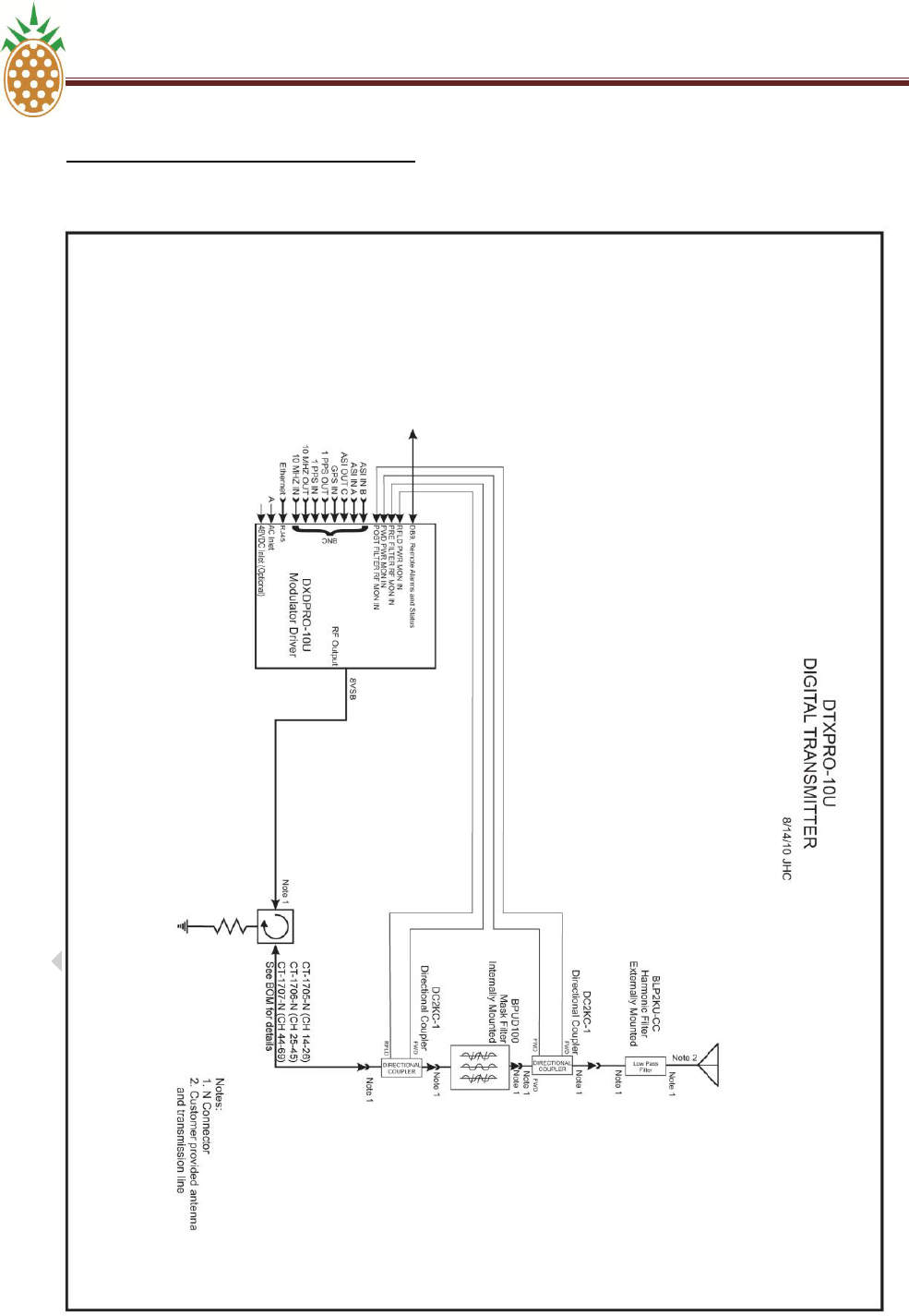
IV. DTXPRO-10U BLOCK DIAGRAM

PINEAPPLE TECHNOLOGY, INC. IV. DTXPRO-10U BLOCK DIAGRAM AND BILL OF MATERIALS
DTXPRO-10U OPERATING AND SERVICE MANUAL
THE INFORMATION PROVIDED HEREIN IS PINEAPPLE TECHNOLOGY INCORPORATED PROPRIETARY INFORMATION AND
CANNOT BE COPIED OR DISTRIBUTED WITHOUT PRIOR AUTHORIZATION
11
IV. DTXPRO-10U BILL OF MATERIALS
DXDPRO-10U - MODULATOR, DIGITAL, UHF, ADAPTIVE, 10W RMS……………….
1
ea
DC2KC-1 - DC, 2KW RMS, UHF, N M/F……………………………………………………
2
ea
BPUD100 - FILTER, UHF, 100W RMS, TYPE N FEMALE………………………………
1
ea
BLP2KU-CC – HARMONIC FILTER ……………………………………….……………...
1
ea
The following part is dependent upon the channel selected:…………………………….
CT-1705-N ISO 100 W N CONN UHF 470-548 MHz (Channels 14-26)
CT-1706-N ISO 100W N CONN UHF 542-656 MHz (Channels 25-45)
CT-1707-N ISO 100W TYPE N 650-806 MHz (Channels 44-69)
1
ea

THE INFORMATION PROVIDED HEREIN IS PINEAPPLE TECHNOLOGY INCORPORATED PROPRIETARY INFORMATION AND
CANNOT BE COPIED OR DISTRIBUTED WITHOUT PRIOR AUTHORIZATION
12
SECTION V
DXDPRO-10U
MODULATOR
MANUAL

PINEAPPLE TECHNOLOGY, INC. V.1 DXDPRO-10U INTRODUCTION
DTXPRO-10U OPERATING AND SERVICE MANUAL
THE INFORMATION PROVIDED HEREIN IS PINEAPPLE TECHNOLOGY INCORPORATED PROPRIETARY
INFORMATION AND CANNOT BE COPIED OR DISTRIBUTED WITHOUT PRIOR AUTHORIZATION
13
V.1. DXDPRO-10U INTRODUCTION
Pineapple Technology Inc. (PTI) is proud to introduce the DXDPRO and DTXPRO line of
modulators and transmitters. This is the most advanced line of transmission products
available on the market for low power television (LPTV), mobile/hand held (M/H), translators,
and media flow.
The product introduced by Pineapple Technology Inc. covers the following key areas of
advanced telecommunications technology:
1. Adaptive modulator technology
2. Multimode modulation options on a common platform
3. High power amplifiers (HPA) utilizing state-of-the-art 48 volt LDMOS devices
These products are designed to be modular and field serviceable. In most cases it is
possible to diagnose problems via an Ethernet connection. This minimizes service time and
reduces down time. PTI‘s field support plan calls for stocking complete and tested
modulator assemblies for quick delivery to the site. PTI maintains a 24/7 hot line for field
support with access to engineering and technician support as needed.

THE INFORMATION PROVIDED HEREIN IS PINEAPPLE TECHNOLOGY INCORPORATED PROPRIETARY INFORMATION AND
CANNOT BE COPIED OR DISTRIBUTED WITHOUT PRIOR AUTHORIZATION
14
SECTION V.2
DXDPRO-10U
TECHNICAL
SPECIFICATIONS

PINEAPPLE TECHNOLOGY, INC. V.2. DXDPRO-10U TECHNICAL SPECIFICATIONS
DTXPRO-10U OPERATING AND SERVICE MANUAL
THE INFORMATION PROVIDED HEREIN IS PINEAPPLE TECHNOLOGY INCORPORATED PROPRIETARY INFORMATION AND
CANNOT BE COPIED OR DISTRIBUTED WITHOUT PRIOR AUTHORIZATION
15
V.2 DXDPRO-10U TECHNICAL SPECIFICATIONS
ELECTRICAL SPECIFICATIONS
PRIMARY POWER....................................
(AC) 110/220 50/60 Cycles Universal Power
(DC) 48 VDC Nominal 44-52 VDC Operating Range
ELECTRICAL STANDARDS.....................
8vsb ATSC Transmission
ATSC: A/53, A54, A64, SMPTE-310M
DVB-ASI: EN50083-9, ETSI TR 101 819
MPEG-TS ISO/IEC 13818-1
SIGNAL PERFORMANCE...........................
MD Shoulders and MER/SNR
Upper Typical -55db (FCC STDR)
Lower Typical -55dB (FCC STDR)
MER/SNR TYPICAL -37Db
CREST FACTOR LIMITING .......................
2-12.5db Adjustable
OPERATING FREQUENCY........................
30 – 1000 MHz Any Channel
OUTPUT POWER LEVEL...........................
0 dBm into 50ohm Load
INPUT TRANSPORT STREAM..................
ASI OR SMPTE-310M
WEB PAGE VIA ETHERNET......................
Remote Controled Features Are Included
(REMOTE OR LOCAL)...............................
Linear And Non-Linear Adaptive Correction
Transport Stream Selection
Output Level Adjustment
Mute/Un-Mute Control
Three (3) Level Password Protection
Up To 12 Alarm Signals
Up To 12 Analog Monitoring Ports
ALC And Power Set Features.
PROTECTION CIRCUITS............................
High Reflected Power
Over Temperature Protection

PINEAPPLE TECHNOLOGY, INC. V.2. DXDPRO-10U TECHNICAL SPECIFICATIONS
DTXPRO-10U OPERATING AND SERVICE MANUAL
THE INFORMATION PROVIDED HEREIN IS PINEAPPLE TECHNOLOGY INCORPORATED PROPRIETARY INFORMATION AND
CANNOT BE COPIED OR DISTRIBUTED WITHOUT PRIOR AUTHORIZATION
16
V.2. DXDPRO-10U TECHNICAL SPECIFICATIONS (Continued)
ELECTRICAL SPECIFICATIONS (Continued)
REMOTE MONITORING..............................
Output Power Level
Reflected Power Level
DC Supply Voltage
DC Current
AC Main Voltage
Heat Sink Temperature
Ambient Temperature
ALARMS.....................................................
Over Temp
Low Supply Voltage
High Reflected Power
Low Output Power
Intruder
AC Main Power
PA1 Current Low
PA2 Current Low
PA3 Current Low
PA4 Current Low
PA5 Current Low
REMOTE MONITORING..............................
Output Power Level
Reflected Power Level
DC Supply Voltage
DC Current
AC Main Voltage
Heat Sink Temperature
Ambient Temperature
MECHANICAL SPECIFICATIONS
Size...............................................................
Height 1.65 in (41.91) mm
Width 17.25 in (438.1) mm
Depth 17 in (431.8) mm
Weight <8 lbs. (3.63) kg
Construction..................................................
All With Gold Alodyne Finish

THE INFORMATION PROVIDED HEREIN IS PINEAPPLE TECHNOLOGY INCORPORATED PROPRIETARY INFORMATION AND
CANNOT BE COPIED OR DISTRIBUTED WITHOUT PRIOR AUTHORIZATION
17
SECTION V.3
DXDPRO-10U
APPLICATIONS
AND
INSTALATION
PINEAPPLE TECHNOLOGY, INC. V.3. DXDPRO-10U APPLICATIONS AND
INSTALLATION
DTXPRO-10U OPERATING AND SERVICE MANUAL
THE INFORMATION PROVIDED HEREIN IS PINEAPPLE TECHNOLOGY INCORPORATED PROPRIETARY INFORMATION AND
CANNOT BE COPIED OR DISTRIBUTED WITHOUT PRIOR AUTHORIZATION
18
V.3 DXDPRO-10U APPLICATIONS AND INSTALLATION
A. APPLICATIONS
The DXDPRO Modulator line was developed to process ASI or SMPTE-310M transport streams and
convert them into an ATSC Compliant signal for Television Broadcast transmission. Additional broadcast
formats are available i.e. H/M, xxx, and others.
Models available in this family of products include:
a. DXDPRO-MB - This is the ―BASE MODEL‖. This modulator can be used on all channels for
UHF, VHF High Band, or VHF Low Band TV Channels between 45 and 900 MHz.
b. DXDPRO-MBR - Built in receiver for Translator/Transposers with 0 dBm output on any channel
between 45 and 900 MHz.
c. DXDPRO-10U - Transmitter modulator for UHF TV with 10 W average digital power output.
Excellent for high power transmitter.
d. DXDPRO-10UR - Built in receiver for Translator/Transposer with 10 W average digital power
output on UHF TV Channels.
e. DXDPRO-10VH - Transmitter modulator for VHF High Band TV Transmitter with 10 W average
digital power output. Excellent for high power transmitters.
f. DXDPRO-10VHR - Built in receiver for Translator/Transposers with 10 W average digital power
output on all VHF High Band TV Channels.
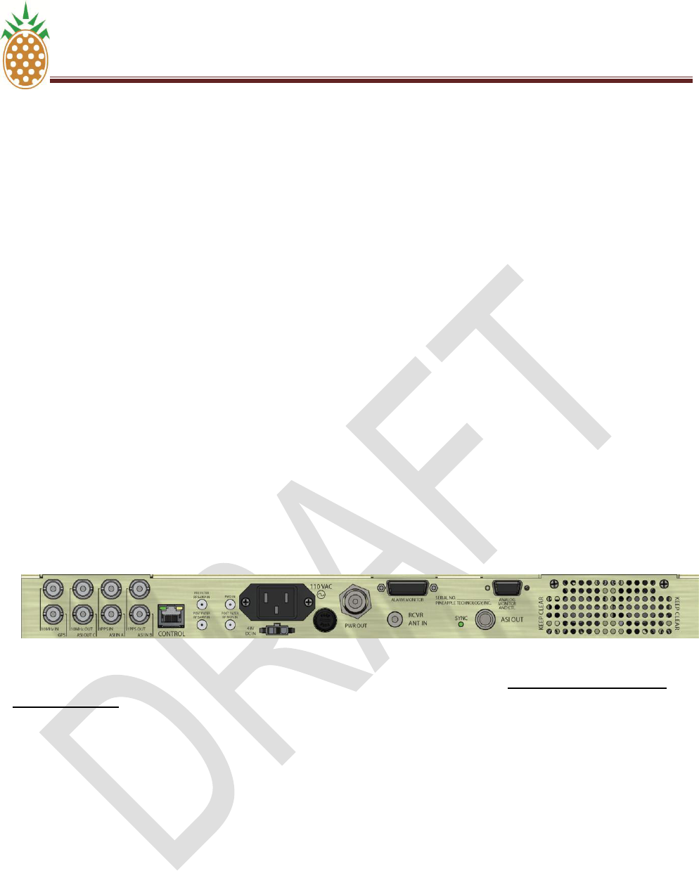
B. TRANSMITTER INSTALATION
The modulator is enclosed in a convenient one (1) RU 19 inch package. This allows installation into most
standard rack. Do not use the front panel to hold up the modulator in the rack. RACK SUPPORT RAILS
MUST BE USED. All cable connections are located on the rear of the chassis. Several cable types are
used to make necessary connections. Please review the following list;
1. SMA 50 ohm connectors with RG 223 cable should be used for linear and non-linear connections
between the modulator and the directional couplers located before and after the mask filter. A
similar set of cables should be used to connect the forward and reflected power sample for the
Modulators power meter.
2. Type N 50 ohm connector with RG 223 or RG 8 cable can be used for the RF Output
3. DB15 cable for alarm input
4. DB9 cable for analog and control functions
5. AC Inlet (filtered) type
6. Molex 3 p connector of 48 VDC Auxiliary input
7. RJ-45 Ethernet connection
8. GPS 1pps or 10 MHz BNC 75 ohm connections
9. ASI OR SMPTE-310M BNC 75 ohm connections

PINEAPPLE TECHNOLOGY, INC. V.3. DXDPRO-10U APPLICATIONS AND
INSTALLATION
DTXPRO-10U OPERATING AND SERVICE MANUAL
THE INFORMATION PROVIDED HEREIN IS PINEAPPLE TECHNOLOGY INCORPORATED PROPRIETARY INFORMATION AND
CANNOT BE COPIED OR DISTRIBUTED WITHOUT PRIOR AUTHORIZATION
19
V.3 DXDPRO-10U APPLICATIONS AND INSTALLATION
C. DIGITAL UPGRADE NOTES
The DXDPRO-10U is suitable for upgrading analog transmitters to digital service. Special attention must be
given to every detail of the conversion to insure that the desired objective is met and that it is compliant with
FCC requirements. The equipment used to make a conversion is expensive and can be costly. The
following needs to be considered when making a conversion to digital from analog;
1. Replace the modulator with a good quality digital modulator with adaptive linear and non-linear
correction
2. Check the drive level required to achieve the desired output power level from the transmitter. A
driver may be required after the modulator
3. The output band pass filter will have to be replaced with a MASK FILTER. Consider using a Mask
Filter that is rated at 1.25 times the desired output power level.
4. Digital transmitters and mask filters need to be correctable by the modulator. This will require the
addition of dual directional couplers before and after the mask filter to provide correction signals.
5. IMPORTANT: Modification of FCC approved equipment requires special test and test equipment. A
qualified Broadcast engineer should be employed to do this work.
D. 48 VDC OPERATIONS
The DXDPRO-10U Modulator is designed to be used with an external 48 VDC supply similar to those found
at TELECOM SITES. If the Modulator is used with standard AC supplied power sources the DC backup
can be automatically switched with internal circuits. The battery charge level can be monitored on the front
panel or on the web page. The operating range is from 42 to 52 VDC.
E. GPS RECEIVER ACTIVATION
The DXDPRO has a built in GPS receiver. The input port is located as show below;
GPS Receiver
Input
Connection
PINEAPPLE TECHNOLOGY, INC. V.3. DXDPRO-10U APPLICATIONS AND
INSTALLATION
DTXPRO-10U OPERATING AND SERVICE MANUAL
THE INFORMATION PROVIDED HEREIN IS PINEAPPLE TECHNOLOGY INCORPORATED PROPRIETARY INFORMATION AND
CANNOT BE COPIED OR DISTRIBUTED WITHOUT PRIOR AUTHORIZATION
20
V.3 DXDPRO-10U APPLICATIONS AND INSTALLATION
E. GPS RECEIVER ACTIVATION (Continued)
The GPS receiver can be activated by using the Web Page by following these steps:
1. Connect an antenna.
2. Open the web page main menu and select the GPS Icon and pull it down to the lower level of
the web page. A new section on GPS appears.
3. Select the antenna voltage for the receiving antenna. Options are 5 vdc, 3.2 vdc, or none.
4. Check the ―ATIVATE ANTENNA‖
5. Go to the reference window and select ―AUTO‖ AS REFERENCE SOURCE.
GPS Setup
Window

PINEAPPLE TECHNOLOGY, INC. V.3. DXDPRO-10U APPLICATIONS AND
INSTALLATION
DTXPRO-10U OPERATING AND SERVICE MANUAL
THE INFORMATION PROVIDED HEREIN IS PINEAPPLE TECHNOLOGY INCORPORATED PROPRIETARY INFORMATION AND
CANNOT BE COPIED OR DISTRIBUTED WITHOUT PRIOR AUTHORIZATION
21
The modulator is now locked to GPS source and will remain there until changed. If for some reason the
GPS signal is lost, the internal clock is automatically selected and the system continues to operate without
interruption.

THE INFORMATION PROVIDED HEREIN IS PINEAPPLE TECHNOLOGY INCORPORATED PROPRIETARY INFORMATION AND
CANNOT BE COPIED OR DISTRIBUTED WITHOUT PRIOR AUTHORIZATION
22
SECTION V.4
DXDPRO-10U
FRONT PANEL CONTROL
AND
MONITORING
PINEAPPLE TECHNOLOGY, INC. V.4. FRONT PANEL CONTROL AND MONITORING
DTXPRO-10U OPERATING AND SERVICE MANUAL
THE INFORMATION PROVIDED HEREIN IS PINEAPPLE TECHNOLOGY INCORPORATED PROPRIETARY INFORMATION AND
CANNOT BE COPIED OR DISTRIBUTED WITHOUT PRIOR AUTHORIZATION
23
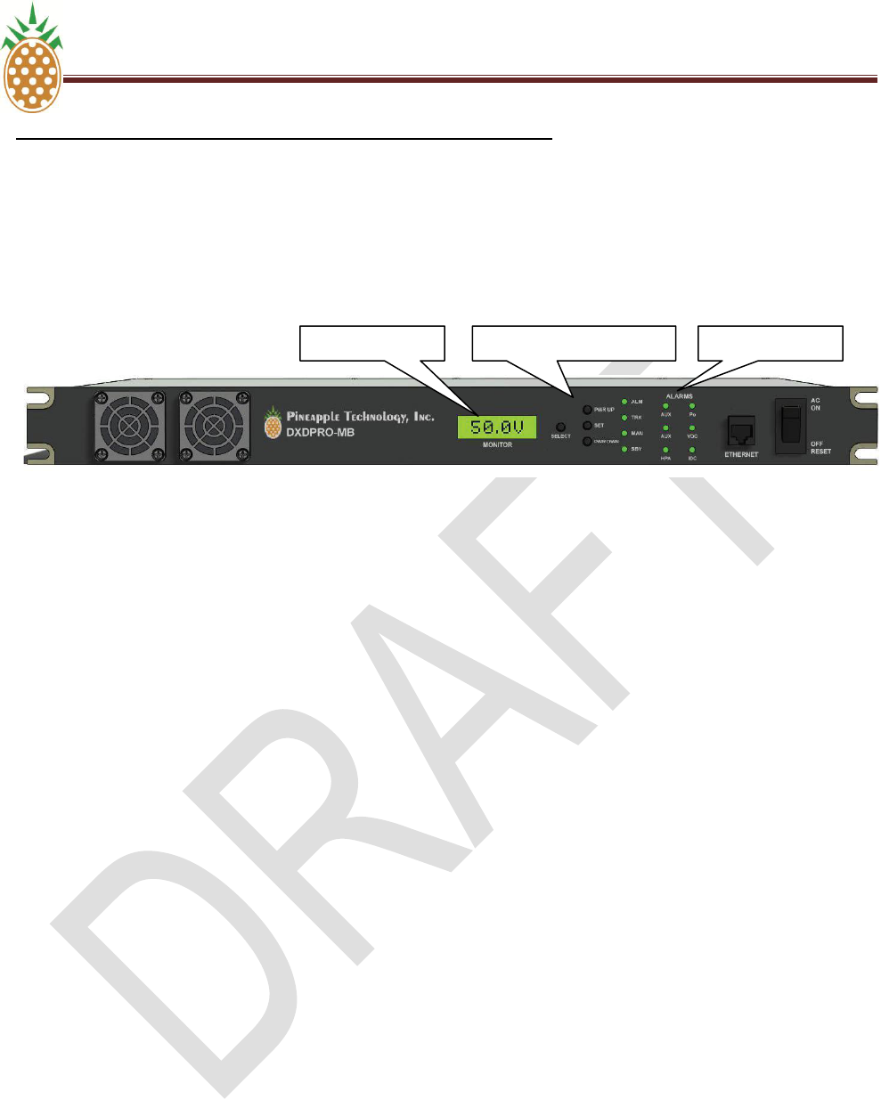
V.4 DXDPRO-10U FRONT PANEL CONTROL AND MONITORING
A. OVERVIEW
The front panel of the DXDPRO-10U modulator has three important functions for transmitter monitoring and
control. Standard on all modulator is an LCD display, display selector switch, ALC and Power Level
adjustments, and alarm display. These areas are show below:
B. TRANSMITTER PERFORMANCE MONITORING
The LCD display will display most all key analog inputs to the modulator as shown below;
1. Transmitter output power in percent (%). 100% being the license TPO.
2. Antenna reflected power in percent (%). Calibrated to 20% maximum before fault.
3. DC 48 VOLTAGE internal or external supply.
4. DC current draw internal and/or external transmitter.
5. Heat sink temperature in degrees Celsius.
6. Internal temperature
7. External temperature
C. ALARM SIGNALS
Key alarms are set according to the addendum attached to this manual and/or listed under the LED on the
front panel.
D. POWER LEVEL ADJUSTMENT AND ALC
The selections are made using the LCD display selector switch shown above. The display changes each
time the switch is enabled.
The ALC/Power Level control panel has three control switches. The switches shown are:
1. Power UP
2. SET
3. Power DWN
The LED to the right of the switches indicates the ALC operating status.
LCD Display
ALC PWR Control
Alarms

THE INFORMATION PROVIDED HEREIN IS PINEAPPLE TECHNOLOGY INCORPORATED PROPRIETARY INFORMATION AND
CANNOT BE COPIED OR DISTRIBUTED WITHOUT PRIOR AUTHORIZATION
24
SECTION V.5
DXDPRO-10U
ETHERNET
WEB PAGE
CONTROL AND
MONITORING
PINEAPPLE TECHNOLOGY, INC. V.5 . ETHERNET WEB PAGE CONTROL AND MONITORING
DTXPRO-10U OPERATING AND SERVICE MANUAL
THE INFORMATION PROVIDED HEREIN IS PINEAPPLE TECHNOLOGY INCORPORATED PROPRIETARY INFORMATION AND
CANNOT BE COPIED OR DISTRIBUTED WITHOUT PRIOR AUTHORIZATION
25
V.5 DXDPRO-10U ETHERNET WEB PAGE CONTROL AND MONITORING
A. LOCAL PC INTERNAL MODEM SETTINGS FOR A FIXED IP
To view the ProTelevision web page used to control operation of the modulator you must set your PC internal
modem for a fixed IP. The following instructions will explain this process.
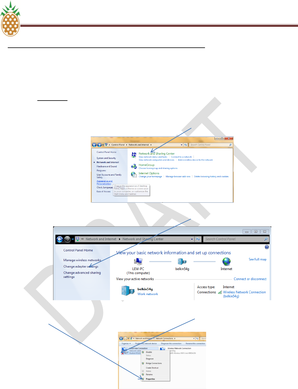
1. For Windows 7 click ―Start‖ then ―Control Panel‖.
a. When the Control Panel window opens click ―Network and Internet‖.
b. When the Network and Internet windows opens click ―Network and Sharing Center‖ (Fig 1)
Fig 1
c. When the Network and Sharing Center opens click on ―Change adapter settings‖ (Fig 2)
Fig 2
d. When the Change adapter settings opens right click on ―Local Area Connection‖ and click on
―Properties‖ from the pop up menu. (Fig 3)
Fig 3
PINEAPPLE TECHNOLOGY, INC. V.5 . ETHERNET WEB PAGE CONTROL AND MONITORING
DTXPRO-10U OPERATING AND SERVICE MANUAL
THE INFORMATION PROVIDED HEREIN IS PINEAPPLE TECHNOLOGY INCORPORATED PROPRIETARY INFORMATION AND
CANNOT BE COPIED OR DISTRIBUTED WITHOUT PRIOR AUTHORIZATION
26
V.5 DXDPRO-10U ETHERNET WEB PAGE CONTROL AND MONITORING
A. LOCAL PC INTERNAL MODEM SETTINGS FOR A FIXED IP
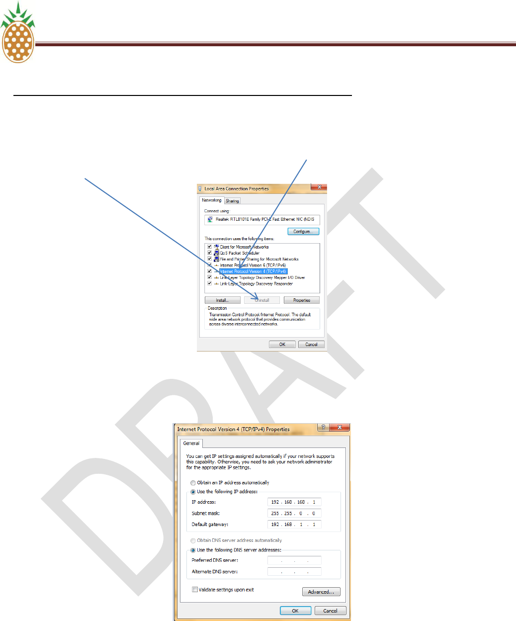
e. When the properties window opens click on ―Internet Protocol Version 4 (TCP/IPv4)‖ to bring it
in focus then click the ―Properties‖ button. (Fig 4)
Fig 4
f. When the Properties window opens click the ―Use the following IP address‖ and fill in the ―IP
address‖, ―Subnet mask‖ and ―Default gateway‖ as shown and click ―OK‖. Fig 5
Fig 5
g. Click ―OK” to close the Local Area Connection Properties window. Close any remaining windows
that are open.
PINEAPPLE TECHNOLOGY, INC. V.5 . ETHERNET WEB PAGE CONTROL AND MONITORING
DTXPRO-10U OPERATING AND SERVICE MANUAL
THE INFORMATION PROVIDED HEREIN IS PINEAPPLE TECHNOLOGY INCORPORATED PROPRIETARY INFORMATION AND
CANNOT BE COPIED OR DISTRIBUTED WITHOUT PRIOR AUTHORIZATION
27
V.5 DXDPRO-10U ETHERNET WEB PAGE CONTROL AND MONITORING
A. LOCAL PC INTERNAL MODEM SETTINGS FOR A FIXED IP
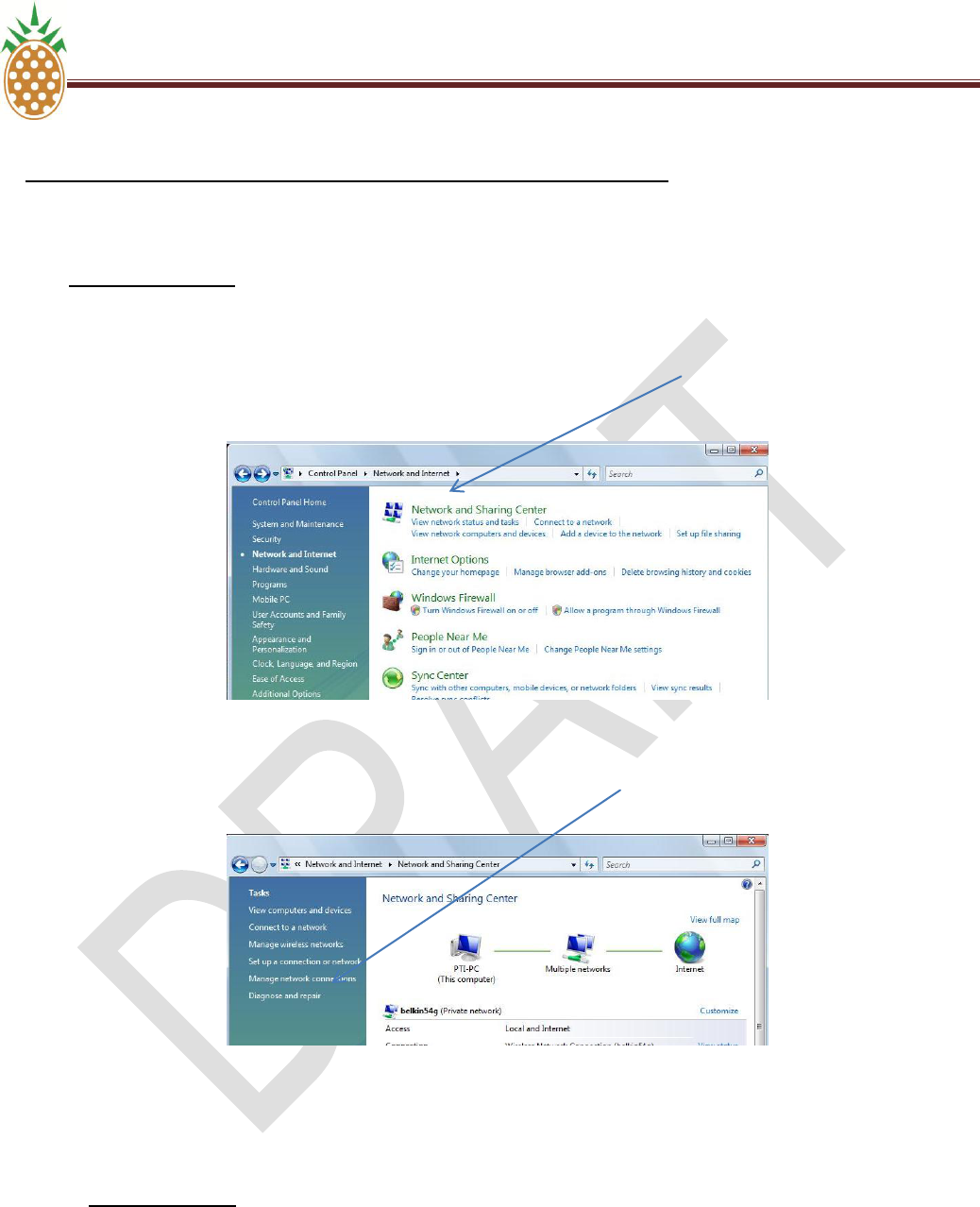
2. For Windows Vista click ―Start‖ then ―Control Panel‖.
a. When the Control Panel window opens click ―Network and Internet‖.
b. When the Network and Internet windows opens click ―Network and Sharing Center‖ (Fig 6)
Fig 6
c. When the window opens click on ―Manage Network Connections‖ (Fig 7)
Fig 7
d. Follow steps ―e‖ through ―g‖ above.
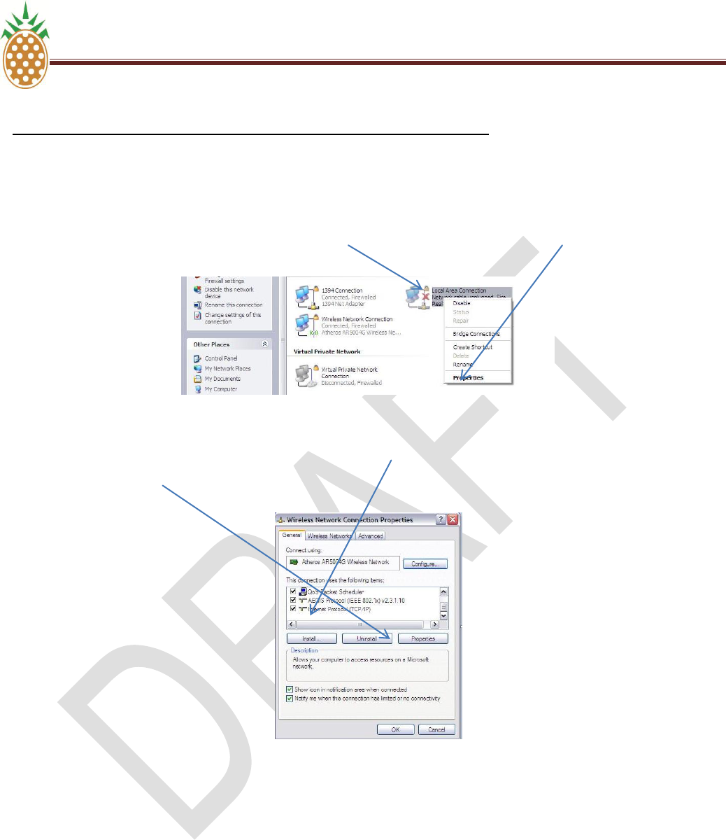
3. For Windows XP click ―Start‖ then ―Control Panel‖.
a. When the Control Panel window opens, click ―Network Connections‖.
PINEAPPLE TECHNOLOGY, INC. V.5 . ETHERNET WEB PAGE CONTROL AND MONITORING
DTXPRO-10U OPERATING AND SERVICE MANUAL
THE INFORMATION PROVIDED HEREIN IS PINEAPPLE TECHNOLOGY INCORPORATED PROPRIETARY INFORMATION AND
CANNOT BE COPIED OR DISTRIBUTED WITHOUT PRIOR AUTHORIZATION
28
V.5 DXDPRO-10U ETHERNET WEB PAGE CONTROL AND MONITORING
A. LOCAL PC INTERNAL MODEM SETTINGS FOR A FIXED IP
b. When the window opens right click ―Local Area Connection‖ and select ―Properties‖ from the
pop-up menu. (Fig 8)
Fig 8
c. When the Properties window opens click ―Internet Protocol (TCP/IP)‖ to bring it into focus and
then select ―Properties‖ (Fig 9)
Fig 9
d. Follow steps ―f‖ and ―g‖ above.
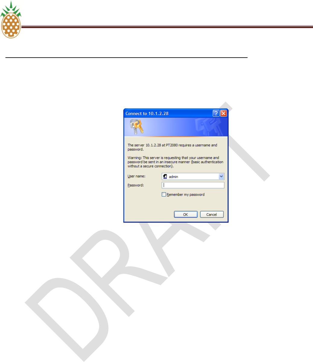
4. You are now ready to open the ProTelevision web page in your browser.
5. Connect your cable from the Ethernet port on your computer to the Ethernet port on the back of the
modulator.
6. Open Internet Explorer or Mozilla Firefox and enter IP address 192.168.168.168 in the address field.
7. Enter the provided User name and Password. You are now ready to control the modulator.

PINEAPPLE TECHNOLOGY, INC. V.5 . ETHERNET WEB PAGE CONTROL AND MONITORING
DTXPRO-10U OPERATING AND SERVICE MANUAL
THE INFORMATION PROVIDED HEREIN IS PINEAPPLE TECHNOLOGY INCORPORATED PROPRIETARY INFORMATION AND
CANNOT BE COPIED OR DISTRIBUTED WITHOUT PRIOR AUTHORIZATION
29
V.5 DXDPRO-10U ETHERNET WEB PAGE CONTROL AND MONITORING
B. ETHERNET WEB PAGE SETUP
General Introduction
The web service control interface allows monitoring of status as well as configuration of the operational
parameters of the device subject to the log-in status for the user (observer, operator or administrator). The user
interface (web browser display) applies a user friendly concept where the general navigation between individual
sub menus is based on a block oriented representation of the controlled device. The specific control for a certain
function is therefore easily accessed by ‗dragging‘ the functional block of interest into the configuration section of
the display.
The web service interface is equally useful for controlling the PT2000 Terrestrial Gateway product in a
configuration with a direct connection (Ethernet patch cable) between the PT2000 Terrestrial Gateway product
and the PC as well as in the typical operational environment where multiple products are accessible from the PC
across a shared network.
Document structure and scope
This instruction manual is divided into three main sections:
Electrical interface and IP address configuration;
Operation principle for the Web service interface; and,
Software update over Ethernet.
The present document describes the operation from a generic viewpoint and it does therefore not address in
detail functions or settings applicable to a specific member of the Terrestrial Gateway product family.
C. IP ADDRESS CONFIGURATI0N
IP address settings for the PT2000 Terrestrial Gateway product can be carried out in several different ways:
a) Hardware preset to default status
b) Configuration over Ethernet (the current address setting must be known and that the PC used for the
configuration must be configured with a compatible address)
1. IP Address Preset
IP address : 192.168.168.168
Network Mask: 255.255.0.0

PINEAPPLE TECHNOLOGY, INC. V.5 . ETHERNET WEB PAGE CONTROL AND MONITORING
DTXPRO-10U OPERATING AND SERVICE MANUAL
THE INFORMATION PROVIDED HEREIN IS PINEAPPLE TECHNOLOGY INCORPORATED PROPRIETARY INFORMATION AND
CANNOT BE COPIED OR DISTRIBUTED WITHOUT PRIOR AUTHORIZATION
30
V.5 . DXDPRO-10U ETHERNET WEB PAGE CONTROL AND MONITORING (Continued)
C. IP ADDRESS CONFIGURATI0N (Continued)
2. IP Configuration Over Ethernet (Terminal)
The PT2000 Terrestrial Gateway product can be configured for either static or dynamic IP address operation.
The factory default setting for the unit is:
Address management: DHCP = OFF (static IP address)
Default IP: 192.168.168.168
Default Mask: 255.255.0.0
Default gateway: 192.168.1.1
Provided that the current IP setting for the unit is known (IP address and network mask) it is possible to carry
out further query of IP settings by connecting a PC to the Ethernet port. (The PC must, of course, be
configured with IP settings that are compatible with the address space currently set for the PT2000 Terrestrial
Gateway product).
3. IP configuration over Ethernet (Web Service)
The factory default setting for the unit is:
Address management: DHCP = OFF (static IP address)
Default IP: 192.168.168.168
Default Mask: 255.255.0.0
Default gateway: 192.168.1.1
Provided that the current IP setting for the unit is known (IP address and network mask), it is possible to carry
out further query of IP settings by connecting a PC to one of the three RJ45 management ports of the PT2000
Terrestrial Gateway product (the PC must of course be configured with IP settings that are compatible with the
address space currently set for the PT2000).

PINEAPPLE TECHNOLOGY, INC. V.5 . ETHERNET WEB PAGE CONTROL AND MONITORING
DTXPRO-10U OPERATING AND SERVICE MANUAL
THE INFORMATION PROVIDED HEREIN IS PINEAPPLE TECHNOLOGY INCORPORATED PROPRIETARY INFORMATION AND
CANNOT BE COPIED OR DISTRIBUTED WITHOUT PRIOR AUTHORIZATION
31
V.5 . DXDPRO-10U ETHERNET WEB PAGE CONTROL AND MONITORING (Continued)
D. WEB SERVICE OPERATION
The PT2000 Terrestrial Gateway product is fully controllable over ethernet by means of the web service function
(web browser control). The PT2000 web service is designed for use with Internet Explorer V7 and Mozilla
Firefox V2 so it is strongly recommended to use one of these two browser types for the operation. The PT2000
Terrestrail Gateway unit must be configured in advance for the same address space as the PC used for the control
and the PC must be connected to one of the TCP/IP mangement eithere directly or over a network.
Preparation Of The Web Browser
The status pages provided by the PT2000 web service are updated in the web server whenever the operational
status of the device changes. However, changes to operational status, occurrence of alarm messages, etc, may be
masked if the web browser is configured for use of locally cached web pages. To ensure that the web browser
always displays the latest status from the PT2000 web service and not displays outdated cached information it
must be configured specifically to check for newer versions of a web page on every visit to the page. For Microsoft
Internet Explorer 7 this is done as follows:
a) Select ‗Internet options‘ from the ‗Tools‘ menu.
b) Select ‗Browsing history‘ ‗Settings‘ from the ‗‘General‘ tab page.
c) Make sure ‗Every time I visit the page‘ is ticked.
1. Login To The Web Service
Connection to the web service function is established simply by entering in the Web browsers address field the IP
address assigned to the specific PT2000 Terrestrial Gateway unit. A login window will appear in order to
authenticate the user‘s access to the web service. Login can be made at three different levels:
User
classification
Default User
name
Default
Password
Remarks
Administrator
admin
(no password)
Unrestricted access to all configurable parameters
including IP management and SW/FW upload
Operator
oper
(no password)
Access to all configurable parameters related to the
PT2000 Terrestrial Gateway function excluding
configuration of IP parameters and excluding SW/FW
upload
Observer
observer
(no password)
Only access to status displays and observation of
current status in the configuration pages (no parameter
modification is allowed – ‗submit‘ button disabled.)
PINEAPPLE TECHNOLOGY, INC. V.5 . ETHERNET WEB PAGE CONTROL AND MONITORING
DTXPRO-10U OPERATING AND SERVICE MANUAL
THE INFORMATION PROVIDED HEREIN IS PINEAPPLE TECHNOLOGY INCORPORATED PROPRIETARY INFORMATION AND
CANNOT BE COPIED OR DISTRIBUTED WITHOUT PRIOR AUTHORIZATION
32
V.5 . DXDPRO-10U ETHERNET WEB PAGE CONTROL AND MONITORING (Continued)
D. WEB SERVICE OPERATION
1. Login To The Web Service
Figure 0-1 Login window (administrator status / default password)
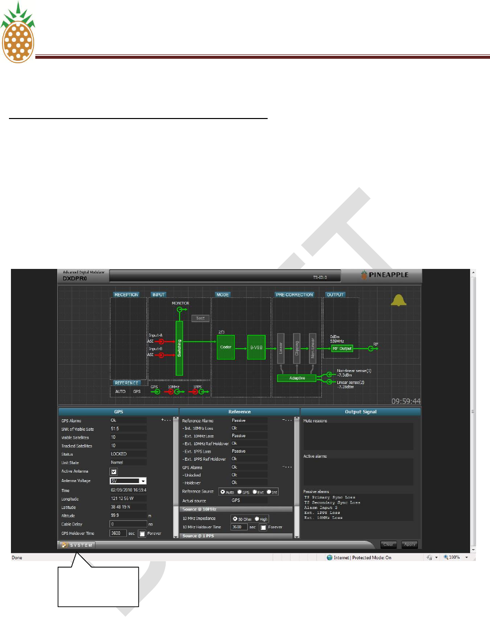
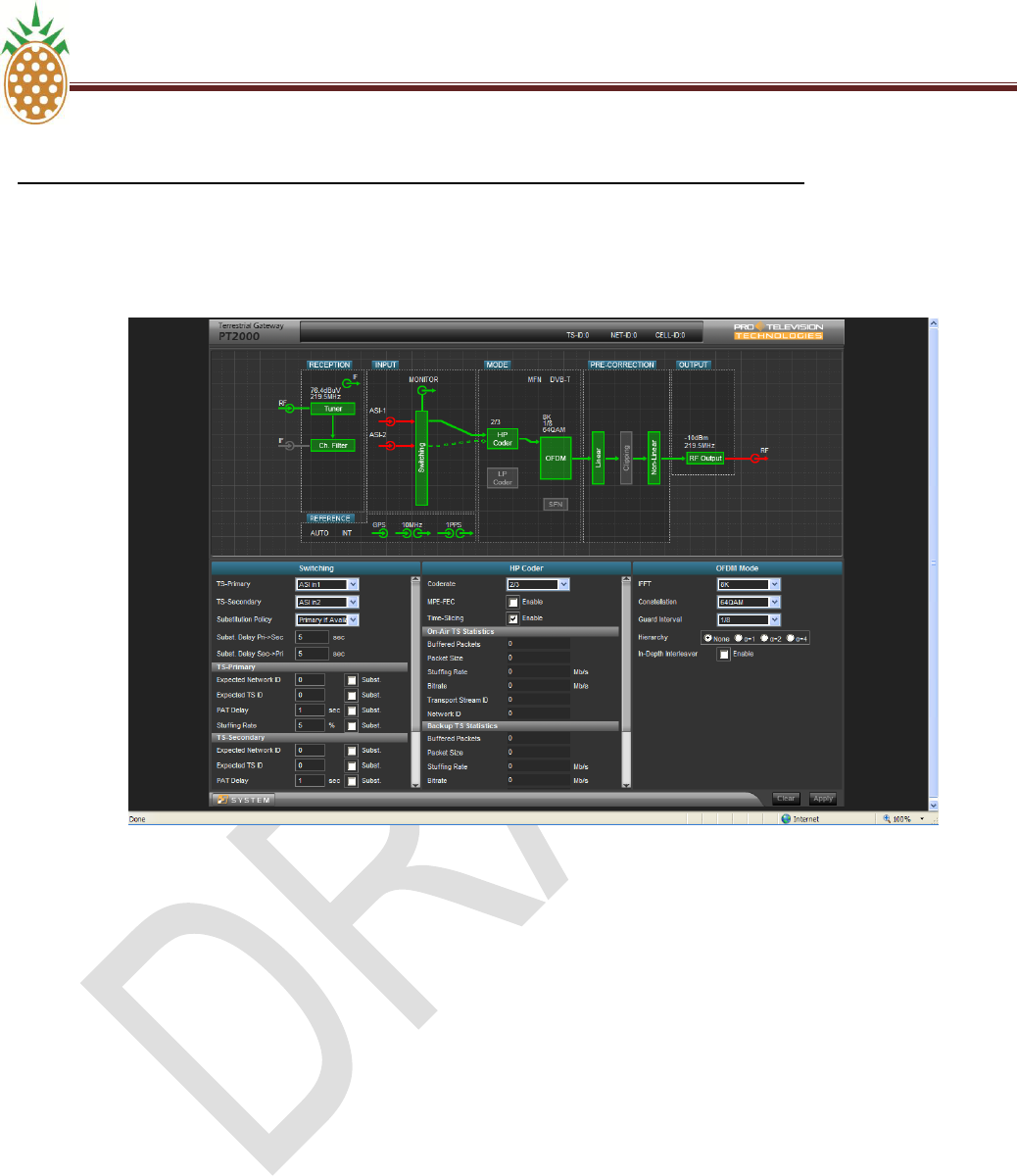
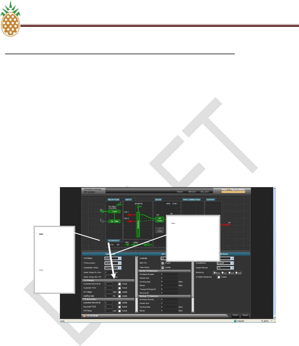
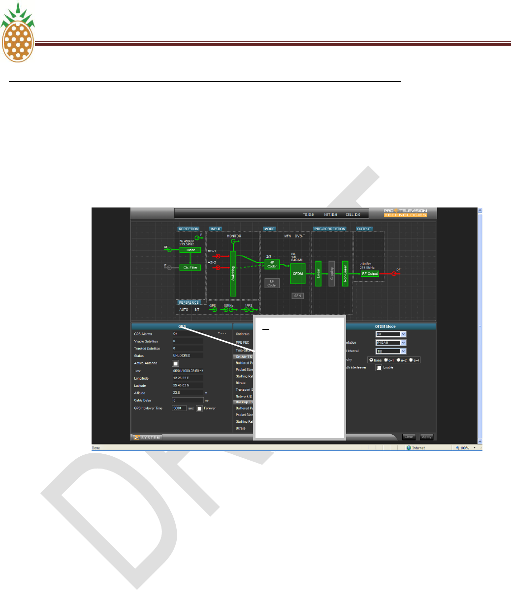
2. Web Service Main Page
Connection to the web service function is established simply by entering in the Web browsers address field the
IP address of the PT2000 Terrestrial Gateway unit. As soon as the connection has been opened the primary
control and status page will appear. The page is divided into an upper section and a lower section.
The upper section provides a graphic representation of the block schematic of the device. The block schematic
provides general status information about the device and serves as navigation tool for accessing specific
status and configuration menus.
The lower section provides space for simultaneous display of three control and status panels for specific
functional areas of the unit. The control panels are easily adapted to the current activity by dragging-and-
dropping the required functional block from the upper section of the screen to the lower section of the screen
(See next page - Section D.- Web Service Operation –- Part 3 - Control Panel Configuration for details).
In case an alarm condition exists for one of the functional elements shown in the upper section of the screen,
the particular element will be shown in red color. Functional elements that are in the normal operational status
will be shown in green color. Functional blocks that are not used in the current configuration are shown in grey
color.
PINEAPPLE TECHNOLOGY, INC. V.5 . ETHERNET WEB PAGE CONTROL AND MONITORING
DTXPRO-10U OPERATING AND SERVICE MANUAL
THE INFORMATION PROVIDED HEREIN IS PINEAPPLE TECHNOLOGY INCORPORATED PROPRIETARY INFORMATION AND
CANNOT BE COPIED OR DISTRIBUTED WITHOUT PRIOR AUTHORIZATION
33
V.5 . DXDPRO-10U ETHERNET WEB PAGE CONTROL AND MONITORING (Continued)
D. WEB SERVICE OPERATION
2. PT 2000 Web Service Main Page
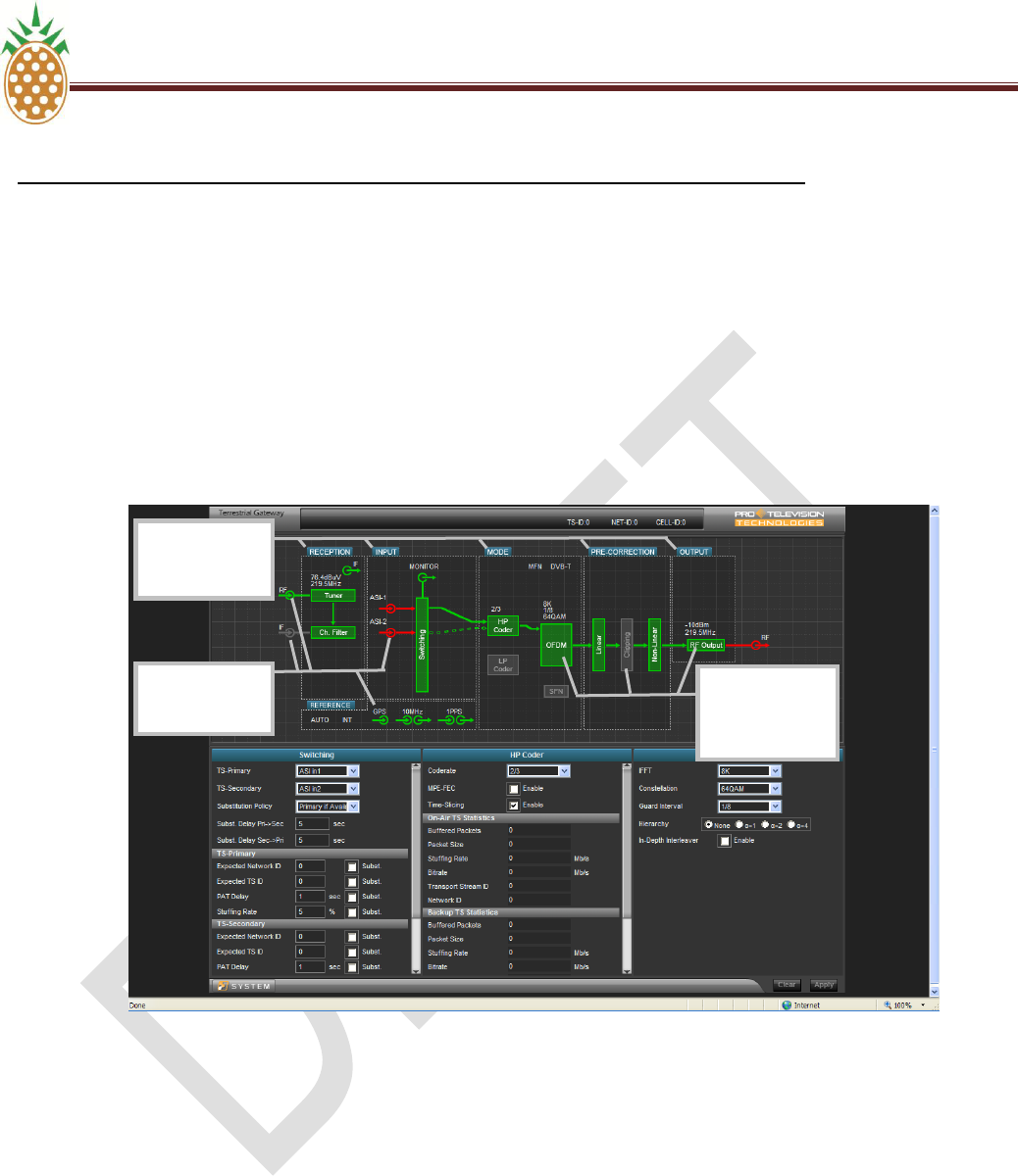
3. Web Service - Operation Principle
Control panel configuration
The control panel (lower section of the screen) is easily adapted to the current activity by dragging-and-
dropping the required functional block from the upper section of the screen to the lower section of the screen.
Control panels for three functional blocks can be open simultaneously in the lower section.
The ‗Functional Blocks‘ in the upper section of the screen can be subdivided into three types:
Main function block: a main function block holds the top level control and status parameters for a
specific function. These blocks are identified by the blue label ‗attached‘ above the block (white text on
blue background). In the below example screen print main functional blocks exist for the sub-functions
Reception, Input, Mode, Pre-Correction, Output and Reference.
Specific function block: a specific function block holds control and status functions for a specific
function within a ‗Main functional block‘. In the below example screen print it can for example be noted
that the Reception main block contains specific functional blocks for the tuner and the channel filter
functions. Likewise, it can be seen that the mode block contains specific functional blocks for the HP
Coder, LP Coder, OFDM and SFN functions.
PINEAPPLE TECHNOLOGY, INC. V.5 . ETHERNET WEB PAGE CONTROL AND MONITORING
DTXPRO-10U OPERATING AND SERVICE MANUAL
THE INFORMATION PROVIDED HEREIN IS PINEAPPLE TECHNOLOGY INCORPORATED PROPRIETARY INFORMATION AND
CANNOT BE COPIED OR DISTRIBUTED WITHOUT PRIOR AUTHORIZATION
34
V.5 . DXDPRO-10U ETHERNET WEB PAGE CONTROL AND MONITORING (Continued)
D. WEB SERVICE OPERATION
3. Web Service - Operation Principle
Control panel configuration
Interface points: The various interface points in and out of the unit presented in the upper section of the
block are themselves mini functional blocks and similar to the main and specific functional blocks these
points can be dragged-and-dropped to the lower section of the screen whenever it‘s desired to check or set
parameters related to the specific point. In the below screen print it can for example be noted that individual
connection points exist for the RF, IF, GPS, 10MHz, 1PPS, MONITOR, IF (out) and RF (out).
Main Function
Block (example)
Specifc
Function Block
Example
(example)
Interface
Point (example)
PINEAPPLE TECHNOLOGY, INC. V.5 . ETHERNET WEB PAGE CONTROL AND MONITORING
DTXPRO-10U OPERATING AND SERVICE MANUAL
THE INFORMATION PROVIDED HEREIN IS PINEAPPLE TECHNOLOGY INCORPORATED PROPRIETARY INFORMATION AND
CANNOT BE COPIED OR DISTRIBUTED WITHOUT PRIOR AUTHORIZATION
35
V.5. DXDPRO-10U ETHERNET WEB PAGE CONTROL AND MONITORING (Continued)
D. WEB SERVICE OPERATION
3. Web Service - Operation Principle
Parameter Control for Main Function Block
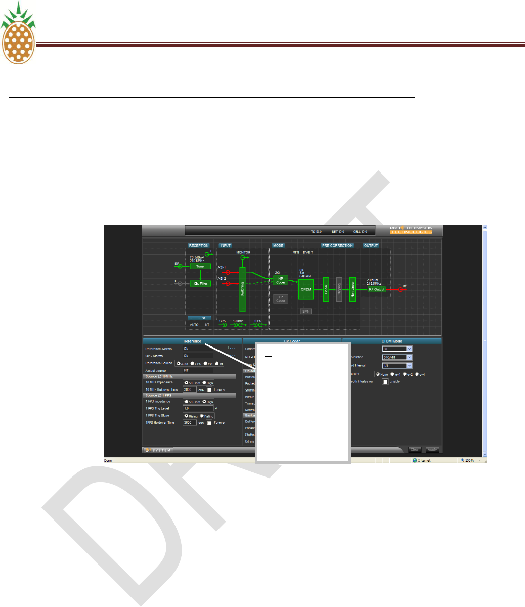
To access the control panel for a main function block (for example the ‗Reference‘ block) proceed as follows:
1. Place the cursor over the blue label of the block of interest (for example the ‗Reference‘ block).
2. Press the left mouse button
3. While keeping the left mouse button pressed drag the block to the lower section of the screen
4. When the block has been dragged to the lower section release the left mouse button. The control panel
that is associated with the block will now open in place of the panel over which the block was dropped.
The block may freely be dropped in any of the three panels (left, centre or right) in accordance with the
preferences.
1.
Place the
cursor over
the blue label.
2.
Press the left
mouse key
3.
While keeping the
left mouse key
pressed drag the
block to the lower
section of the screen
PINEAPPLE TECHNOLOGY, INC. V.5 . ETHERNET WEB PAGE CONTROL AND MONITORING
DTXPRO-10U OPERATING AND SERVICE MANUAL
THE INFORMATION PROVIDED HEREIN IS PINEAPPLE TECHNOLOGY INCORPORATED PROPRIETARY INFORMATION AND
CANNOT BE COPIED OR DISTRIBUTED WITHOUT PRIOR AUTHORIZATION
36
V.5 . DXDPRO-10U ETHERNET WEB PAGE CONTROL AND MONITORING (Continued)
D. WEB SERVICE OPERATION
3. Web Service - Operation Principle
Parameter Control for Main Function Block
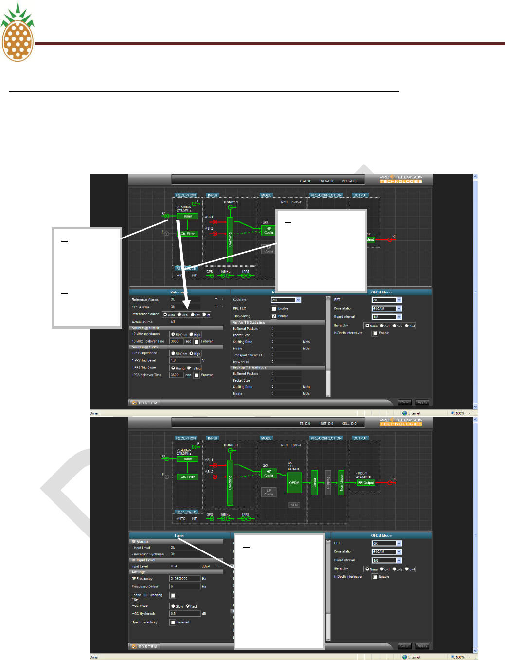
Parameter control for Specific Function Block
To access the control panel for a specific function block (for example the ‗Tuner‘ block) proceed as follows:
1. Place the cursor over the block of interest (for example the ‗Tuner‘ block).
2. Press the left mouse button
3. While keeping the left mouse button pressed drag the block to the lower section of the screen
4. When the block has been dragged to the lower section release the left mouse button. The control panel
that is associated with the block will now open in place of the panel over which the block was dropped.
The block may freely be dropped in any of the three panels (left, center or right) in accordance with the
preferences.
4.
When the block is
placed in the desired
panel (left, centre or
right), release the left
mouse key.
The new control
panel will now
automatically open
PINEAPPLE TECHNOLOGY, INC. V.5 . ETHERNET WEB PAGE CONTROL AND MONITORING
DTXPRO-10U OPERATING AND SERVICE MANUAL
THE INFORMATION PROVIDED HEREIN IS PINEAPPLE TECHNOLOGY INCORPORATED PROPRIETARY INFORMATION AND
CANNOT BE COPIED OR DISTRIBUTED WITHOUT PRIOR AUTHORIZATION
37
V.5 . DXDPRO-10U ETHERNET WEB PAGE CONTROL AND MONITORING (Continued)
D. WEB SERVICE OPERATION
3. Web Service - Operation Principle
Parameter control for Specific Function Block
1.
Place the
cursor over
the block
2.
Press the left
mouse key
3.
While keeping the
left mouse key
pressed drag the
block to the lower
section of the screen
4.
When the block is
placed in the desired
panel (left, centre or
right), release the left
mouse key.
The new control
panel will now
automatically open
PINEAPPLE TECHNOLOGY, INC. V.5 . ETHERNET WEB PAGE CONTROL AND MONITORING
DTXPRO-10U OPERATING AND SERVICE MANUAL
THE INFORMATION PROVIDED HEREIN IS PINEAPPLE TECHNOLOGY INCORPORATED PROPRIETARY INFORMATION AND
CANNOT BE COPIED OR DISTRIBUTED WITHOUT PRIOR AUTHORIZATION
38
V.5 . DXDPRO-10U ETHERNET WEB PAGE CONTROL AND MONITORING (Continued)
D. WEB SERVICE OPERATION
3. Web Service - Operation Principle
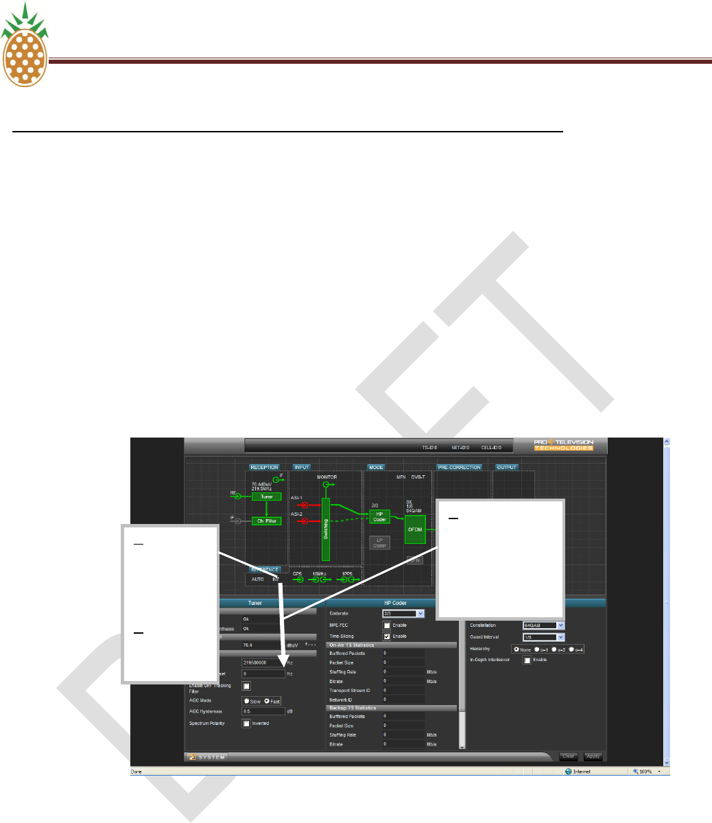
Parameter Control For Interface Point
To access the control panel for a specific Interface point (for example the ‗RF‘ input) proceed as follows:
1. Place the cursor over the interface point of interest (for example the ‗RF‘ input).
2. Press the left mouse button
3. While keeping the left mouse button pressed drag the ‗Interface point‘ to the lower section of the screen
When the ‗Interface point‘ has been dragged to the lower section release the left mouse button. The control
panel that is associated with the connection point will now open in place of the panel over which the Interface
point was dropped. The Interface point may freely be dropped in any of the three panels (left, centre or right) in
accordance with the preferences.
1.
Place the
cursor over
the Interface
point
2.
Press the left
mouse key
3.
While keeping the
left mouse key
pressed drag the
Interface point to the
lower section of the
screen
PINEAPPLE TECHNOLOGY, INC. V.5 . ETHERNET WEB PAGE CONTROL AND MONITORING
DTXPRO-10U OPERATING AND SERVICE MANUAL
THE INFORMATION PROVIDED HEREIN IS PINEAPPLE TECHNOLOGY INCORPORATED PROPRIETARY INFORMATION AND
CANNOT BE COPIED OR DISTRIBUTED WITHOUT PRIOR AUTHORIZATION
39
V.5 DXDPRO-10U. ETHERNET WEB PAGE CONTROL AND MONITORING (Continued)
D. WEB SERVICE OPERATION
3. Web Service - Operation Principle
Parameter Control For Interface Point
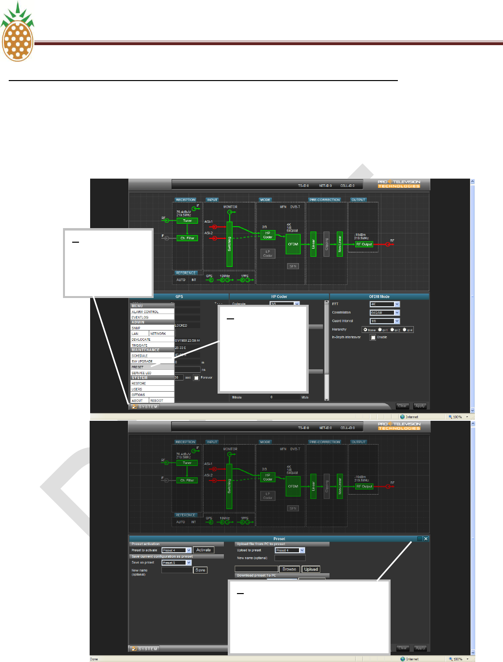
Access To System Parameters
A number of system oriented parameters can be accessed by left-clicking the [System] button located in the
lower-left corner of the web page. To access a specific system (for example saving or loading a device preset)
proceed as follows:
1. Left click the [System] button. A menu including the various choices will now open up above the [system]
button.
2. From the menu select the required function (for example ‗Preset‘ management) by left-clicking the point in the
menu.
3. The corresponding control panel will now open up in the lower section of the screen in place of the three
regular control panels.
4. When the setting of interest has been verified/changed as required the ‗system‘ control panel is closed again
by left clicking the [X] in the top-right corner of the panel.
4.
When the Interface
point is placed in the
desired panel (left,
centre or right),
release the left
mouse key.
The new control
panel will now
automatically open
PINEAPPLE TECHNOLOGY, INC. V.5 . ETHERNET WEB PAGE CONTROL AND MONITORING
DTXPRO-10U OPERATING AND SERVICE MANUAL
THE INFORMATION PROVIDED HEREIN IS PINEAPPLE TECHNOLOGY INCORPORATED PROPRIETARY INFORMATION AND
CANNOT BE COPIED OR DISTRIBUTED WITHOUT PRIOR AUTHORIZATION
40
V.5 . DXDPRO-10U ETHERNET WEB PAGE CONTROL AND MONITORING (Continued)
D. WEB SERVICE OPERATION
3. Web Service - Operation Principle
Access To System Parameters
3:
When the parameter of interest in the
system menu has been verified or set as
required click the [x] to close the system
menu and revert to the normal three-
panel display
2:
From the system
menu select the
required sub menu
(for example
‘Preset‘) by left-
clicking the menu
point
1:
Left-click the
[SYSTEM] button to
open the system
configuration menu.
PINEAPPLE TECHNOLOGY, INC. V.5 . ETHERNET WEB PAGE CONTROL AND MONITORING
DTXPRO-10U OPERATING AND SERVICE MANUAL
THE INFORMATION PROVIDED HEREIN IS PINEAPPLE TECHNOLOGY INCORPORATED PROPRIETARY INFORMATION AND
CANNOT BE COPIED OR DISTRIBUTED WITHOUT PRIOR AUTHORIZATION
41
V.5 DXDPRO-10U. ETHERNET WEB PAGE CONTROL AND MONITORING (Continued)
D. WEB SERVICE OPERATION
3. Web Service - Operation Principle
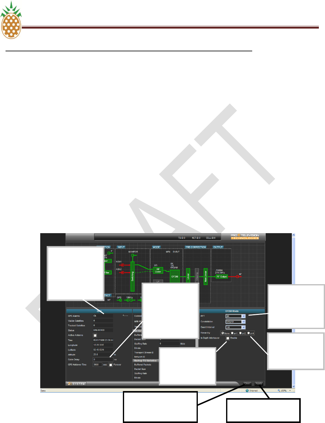
Setting Of A Parameter Value
To change the setting of a specific user parameter, proceed as follows:
1. If not already available for modification move the functional block in which the parameter resides to the
control panel in the lower section of the screen as described above.
2. Place the cursor over the location in the control panel where the parameter of interest resides and click the
left mouse button to set the point in focus. Depending on the type of input set the new value as required.
The input can be ‗alpha-numeric for input by keyboard‘ or based on a drop-down list holding the valid
choices or based on a tick-box or radio-button system. Notice that some fields are status displays only
(read only) and that it consequently isn‘t possible to access these fields for parameter change.
3. When the new value has been specified the border of the field in question will be presented in a light blue
color to indicate that a new value has been specified but not yet implemented/confirmed.
4. To implement/confirm the new value move the cursor to the [Apply] button and click the left mouse button
to confirm the entry.
5. When the new value has implemented/confirmed the light blue border around the parameter input field will
return to the normal black color.
Parameter control of
the ’drop-down’ list
type. The control will
provide the list of valid
choices for selection
when left-clicked with
the mouse.
Parameter control of
the ’radio-button’ type.
Select a new value by
left-clicking the value in
the control.
Parameter control of
the ’tick-box’ type. Left
click the control to
toggle the value
between the two
possible states
Parameter control for
numeric input. Specify
the value using the
keyboard after selecting
the control by left-
clicking the mouse.
Note the grey border
which indicates that this
box accepts user input.
Parameter box of the
read-only type (status
only). This box differs
from the ‘input‘ type of
box by the absence of
the grey border that
characterizes the boxes
for alpha-numeric input.
Apply button for
implementing/confirming the
new parameter value
Clear button for canceling a
modified but not yet
implemented/confirmed
parameter value

PINEAPPLE TECHNOLOGY, INC. V.5 . ETHERNET WEB PAGE CONTROL AND MONITORING
DTXPRO-10U OPERATING AND SERVICE MANUAL
THE INFORMATION PROVIDED HEREIN IS PINEAPPLE TECHNOLOGY INCORPORATED PROPRIETARY INFORMATION AND
CANNOT BE COPIED OR DISTRIBUTED WITHOUT PRIOR AUTHORIZATION
42
V.5 . DXDPRO-10U ETHERNET WEB PAGE CONTROL AND MONITORING (Continued)
D. WEB SERVICE OPERATION
3. Web Service - Operation Principle
SW/FW update
SW/FW update of the PT2000 Terrestrial Gateway product is carried out over the ethernet interface. The
update is based on a so called ‗tarball‘ file that contains the SW/FW images that define the specific product
version (for example a DVB-T/H modulator, an ATSC modulator or a MediaFLO modulator). The typical size of
the ‗tarball‘ is about 16Mb.
The update procedure is as follows:
1. Download the ‗tarball‘ file from the FTP site to a directory on your local network or to the PC that you
are using explicitly for managing the PT2000 Terrestrial Gateway unit or insert the CDROM that
contains the tarball into a CDROM drive on this PC.
2. Connect to the Web service interface of the PT2000 Terrestrial Gateway product as described in
Section D, Web Service Operation--1. Login to the Web Server, page 31.
3. In the lower left corner of the Web service graphical user interface you will find the [System] button.
Click this button to open the system menu.
4. In the system menu select the function [SW Upgrade]. See Section D, Web Service Operation—
Subsection 3- Web Service - Operation Principle - Access to System Parameters, on page 39, for
further details about access to the system menu.
5. In the Maintenance section of the System menu select Software Upgrade
6. Select [Browse] and navigate to the location of the downloaded ‗tarball‘ file
7. Select the file ‗tarball.tgz’ and click [Upload]
8. The loading of the new SW/FW should now start automatically. The progress can be monitored from
the Web service interface. A number of steps including uploading, unpacking and verifying and deleting
files will pass automatically (the processing time is several minutes).
9. When the loading of new SW/FW is completed the unit will automatically reboot. After the reboot the
new SW/FW version is active.
10. The active SW/FW version can be verified after the reboot via the [About] function in the [System]
menu.

THE INFORMATION PROVIDED HEREIN IS PINEAPPLE TECHNOLOGY INCORPORATED PROPRIETARY INFORMATION AND
CANNOT BE COPIED OR DISTRIBUTED WITHOUT PRIOR AUTHORIZATION
43
SECTION V.6
DXDPRO-10U
ADAPTIVE PRE-CORRECTOR
WEB SERVICE OPERATION

PINEAPPLE TECHNOLOGY, INC V.6. ADAPTIVE PRE-CORRECTOR WEB SERVICE OPERATION
DTXPRO-10U OPERATING AND SERVICE MANUAL
THE INFORMATION PROVIDED HEREIN IS PINEAPPLE TECHNOLOGY INCORPORATED PROPRIETARY INFORMATION AND
CANNOT BE COPIED OR DISTRIBUTED WITHOUT PRIOR AUTHORIZATION
44
V.6. DXDPRO-10U ADAPTIVE PRE-CORRECTOR WEB SERVICE OPERATION
A. INTRODUCTION
This section describes the web browser based operation of the Adaptive pre-corrector for the PT2000
Terrestrial Gateway unit. For an introduction to IP address configuration, log-in procedure and general
operation principle for the web service1 control interface for the DXDPRO product family please refer to the
separate publication DXDPRO Modulator and Repeater Products Web service Interface Instruction Manual
available from Pineapple Technology, Inc..
The web service control interface allows monitoring of status as well as configuration of the operational
parameters of the adaptive pre-corrector device subject to the log-in status for the user (observer, operator
or administrator). The user interface (web browser display) applies a user friendly concept where the general
navigation between individual sub menus is based on a block oriented representation of the controlled
device. The specific control for a certain function is therefore easily accessed by ‗dragging‘ the functional
block of interest into the configuration section of the display.
The web service interface is equally useful for controlling any of the PT2000 Terrestrial Gateway products in
a configuration with a direct connection (Ethernet patch cable) between the PT2000 Terrestrial Gateway unit
and the PC as well as in the typical operational environment where multiple products are accessible from the
PC across a shared network.
SECTION STRUCTURE AND SCOPE
This section is divided into three main chapters:
a. Electrical interface for the adaptive pre-corrector
b. Operation principle for adaptive pre-corrector
c. Application of the adaptive pre-corrector in combination with Echo Canceller option
.
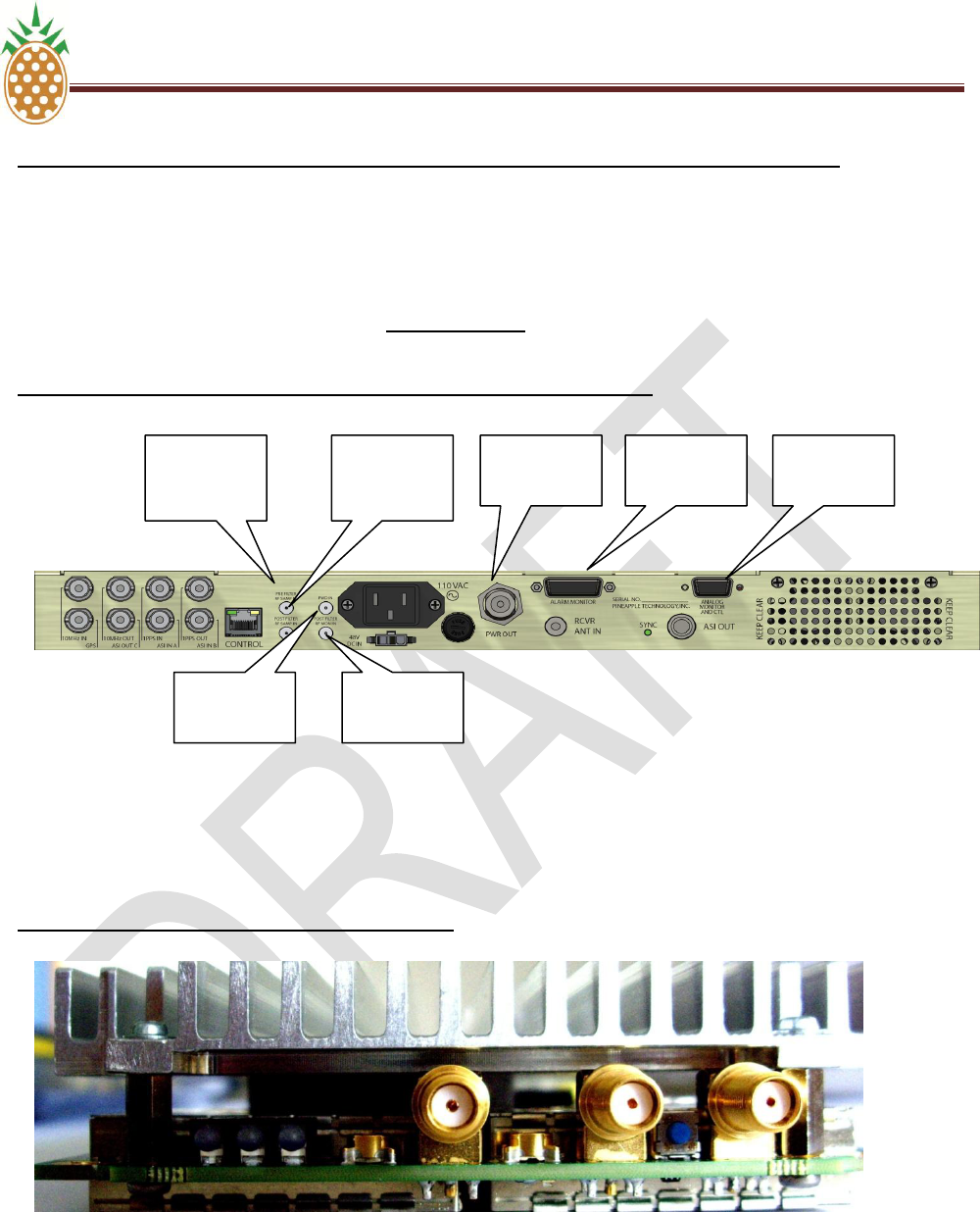
B. ELECTRICAL INTERFACE
1. General information
The adaptive pre-corrector‘s electrical interface consists of two SMA type coaxial connectors:
Sense input 1: Non-linear sense port
Sense input 2: Linear sense port
PINEAPPLE TECHNOLOGY, INC V.6. ADAPTIVE PRE-CORRECTOR WEB SERVICE OPERATION
DTXPRO-10U OPERATING AND SERVICE MANUAL
THE INFORMATION PROVIDED HEREIN IS PINEAPPLE TECHNOLOGY INCORPORATED PROPRIETARY INFORMATION AND
CANNOT BE COPIED OR DISTRIBUTED WITHOUT PRIOR AUTHORIZATION
45
V.6 DXDPRO-10U ADAPTIVE PRE-CORRECTOR WEB SERVICE OPERATION (Continued)
B. ELECTRICAL INTERFACE
The required signal level for both inputs is 0dBm +/-10dB. The impedance is 50 ohm.
Location of sense inputs (stand alone 1RU/19” rack mount chassis):
Location of sense inputs (OEM board version):
Non-linear
Sense-1
Linear
Sense-2
RF output
Non-linear
Sense-1
Linear
Sense-2
RF output
FWRD
PWR
RFLD
PWR
ALARM
INPUTS
ANALOG
AND CTL
PINEAPPLE TECHNOLOGY, INC V.6. ADAPTIVE PRE-CORRECTOR WEB SERVICE OPERATION
DTXPRO-10U OPERATING AND SERVICE MANUAL
THE INFORMATION PROVIDED HEREIN IS PINEAPPLE TECHNOLOGY INCORPORATED PROPRIETARY INFORMATION AND
CANNOT BE COPIED OR DISTRIBUTED WITHOUT PRIOR AUTHORIZATION
46
V.6 DXDPRO-10U ADAPTIVE PRE-CORRECTOR WEB SERVICE OPERATION (Continued)
B. ELECTRICAL INTERFACE
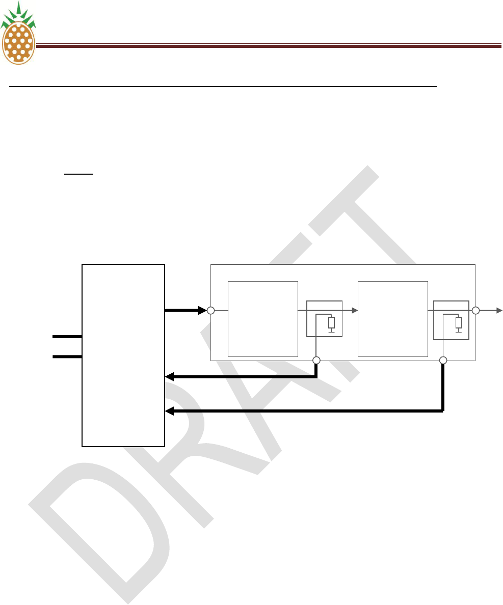
2. Interface to the Transmitter
The non-linear sense input must be connected to a suitable coupler/tap-off at a point right after the power
amplifier before any band limiting filter. The linear sense input must be connected to a suitable
coupler/tap-off point after the channel filter. Notice further that the bandwidth between the RF output of
PT2160 and the input of the power amplifier must be at least 20MHz wide to ensure effective non-linear
pre-correction of the amplifiers non-linearity.
PTPT
C. OPERATION OF ADAPTIVE PRE-CORRECTOR
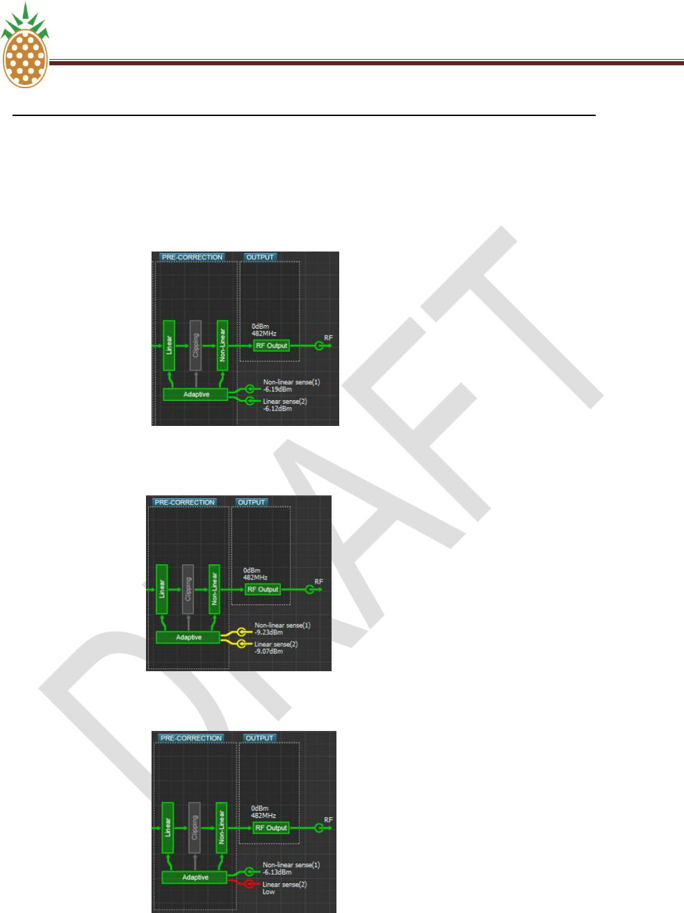
1. Connection and Verification of Signal Levels
The RF output and the sense inputs of the PT2000 Terrestrial Gateway unit must be connected as described
in above in Sub-section 2 - Interface to the Transmitter. The graphical illustration of the two sense inputs in
the web service block schematic will appear in green color if the level is within the valid range for the
respective input. If the level is marginal relative to the required max/min limits the input will be shown in
yellow color. If the level is outside the valid range the input is shown in red color. For optimal result the
corrector should only be operated with input levels in the ‗green‘ state. Performance with ‗yellow‘ input state
is not guaranteed. The adaptive pre-corrector is not usable when the level is in the ‗red‘ state.
PT2160
Power
Amplifier
Channel
Filter
RF out
Sense-1
Non-Linear
Sense-2
Linear
PINEAPPLE TECHNOLOGY, INC V.6. ADAPTIVE PRE-CORRECTOR WEB SERVICE OPERATION
DTXPRO-10U OPERATING AND SERVICE MANUAL
THE INFORMATION PROVIDED HEREIN IS PINEAPPLE TECHNOLOGY INCORPORATED PROPRIETARY INFORMATION AND
CANNOT BE COPIED OR DISTRIBUTED WITHOUT PRIOR AUTHORIZATION
47
V.6 DXDPRO-10U ADAPTIVE PRE-CORRECTOR WEB SERVICE OPERATION (Continued)
C. OPERATION OF ADAPTIVE PRE-CORRECTOR
1. Connection and Verification of Signal Levels (Continued)
Valid sense input for linear and non-linear pre-corrector:
Marginal sense input for linear and non-linear pre-corrector (yellow warning):
Invalid sense input for linear pre-corrector. Valid sense input for non-linear corrector.
PINEAPPLE TECHNOLOGY, INC V.6. ADAPTIVE PRE-CORRECTOR WEB SERVICE OPERATION
DTXPRO-10U OPERATING AND SERVICE MANUAL
THE INFORMATION PROVIDED HEREIN IS PINEAPPLE TECHNOLOGY INCORPORATED PROPRIETARY INFORMATION AND
CANNOT BE COPIED OR DISTRIBUTED WITHOUT PRIOR AUTHORIZATION
48
V.6 DXDPRO-10U ADAPTIVE PRE-CORRECTOR WEB SERVICE OPERATION (Continued)
C. OPERATION OF ADAPTIVE PRE-CORRECTOR
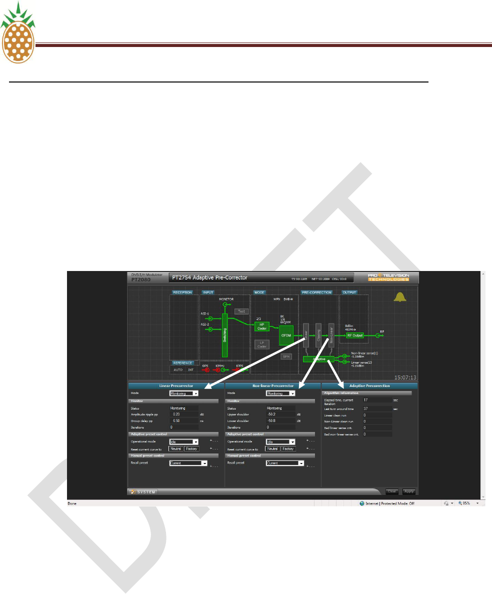
2. Preparation of Web Service Interface
To enable web service control of the non-linear and linear adaptive pre-corrector, proceed as follows:
a) Drag the linear pre-corrector block to the configuration panel
b) Drag the non linear pre-corrector block to the configuration panel
c) Drag the adaptive pre-corrector block to the configuration panel (this panel provides status info
only and it is therefore as such not strictly required for operation of the adaptive system)
d) Drag the three control blocks into the configuration panel one-by-one:
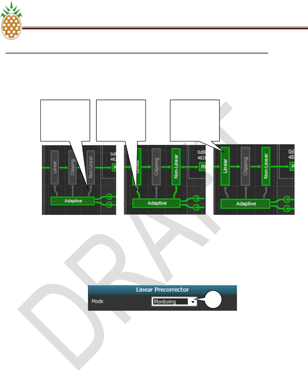
Depending on the current operational mode for the pre-corrector system the linear and non-linear blocks
may appear in grey or in green. When the pre-corrector function is disabled the respective block (linear
and/or non-linear) is shown in grey. When the pre-corrector function is enabled the respective block
(linear and/or non-linear) is shown in green color. When the active pre-corrector mode is ‗adaptive‘ a
green arrow will connect the adaptive function block and the respective pre-corrector block. When the
adaptive pre-corrector mode is ‗static‘ (manual correction mode) the connection between the adaptive
function block and the respective pre-corrector block is grayed out.
PINEAPPLE TECHNOLOGY, INC V.6. ADAPTIVE PRE-CORRECTOR WEB SERVICE OPERATION
DTXPRO-10U OPERATING AND SERVICE MANUAL
THE INFORMATION PROVIDED HEREIN IS PINEAPPLE TECHNOLOGY INCORPORATED PROPRIETARY INFORMATION AND
CANNOT BE COPIED OR DISTRIBUTED WITHOUT PRIOR AUTHORIZATION
49
V.6 DXDPRO-10U ADAPTIVE PRE-CORRECTOR WEB SERVICE OPERATION (Continued)
C. OPERATION OF ADAPTIVE PRE-CORRECTOR
2. Preparation of Web Service Interface (Continued)
3. Linear Pre-Corrector Configuration
Linear Pre-Corrector Mode Selection
The linear pre-corrector system can operate in three different modes. The required mode is selected by
opening the operational mode ‗drop-down‘ list (I).
The available modes are:
Monitoring: No pre-correction is applied to the RF output (the corrector characteristic is
neutral). The amplitude ripple and the group delay performance is measured and displayed
provided that a valid feedback is applied to the RF sense input 2.
Static: The currently loaded manual linear pre-corrector characteristic is applied to the RF
output. The manual pre-corrector characteristics must be generated and uploaded by means of
the PC software package IMD Buster McTwo. The curve format used by the manual pre-
corrector system is incompatible with the curves used and generated by the adaptive system.
Adaptive: The current adaptive linear pre-corrector characteristic is applied and maintained
according to the adaptive pre-corrector mode selected (see below for details).
Adaptive
Linear Pre-
Correction
Disabled
Disabled
Adaptive
Linear Pre-
Correction
Enabled
Adaptive
Correction In
Static Mode
I
I
PINEAPPLE TECHNOLOGY, INC V.6. ADAPTIVE PRE-CORRECTOR WEB SERVICE OPERATION
DTXPRO-10U OPERATING AND SERVICE MANUAL
THE INFORMATION PROVIDED HEREIN IS PINEAPPLE TECHNOLOGY INCORPORATED PROPRIETARY INFORMATION AND
CANNOT BE COPIED OR DISTRIBUTED WITHOUT PRIOR AUTHORIZATION
50
V.6 DXDPRO-10U ADAPTIVE PRE-CORRECTOR WEB SERVICE OPERATION (Continued)
C. OPERATION OF ADAPTIVE PRE-CORRECTOR
3. LINEAR PRE-CORRECTOR CONFIGURATION
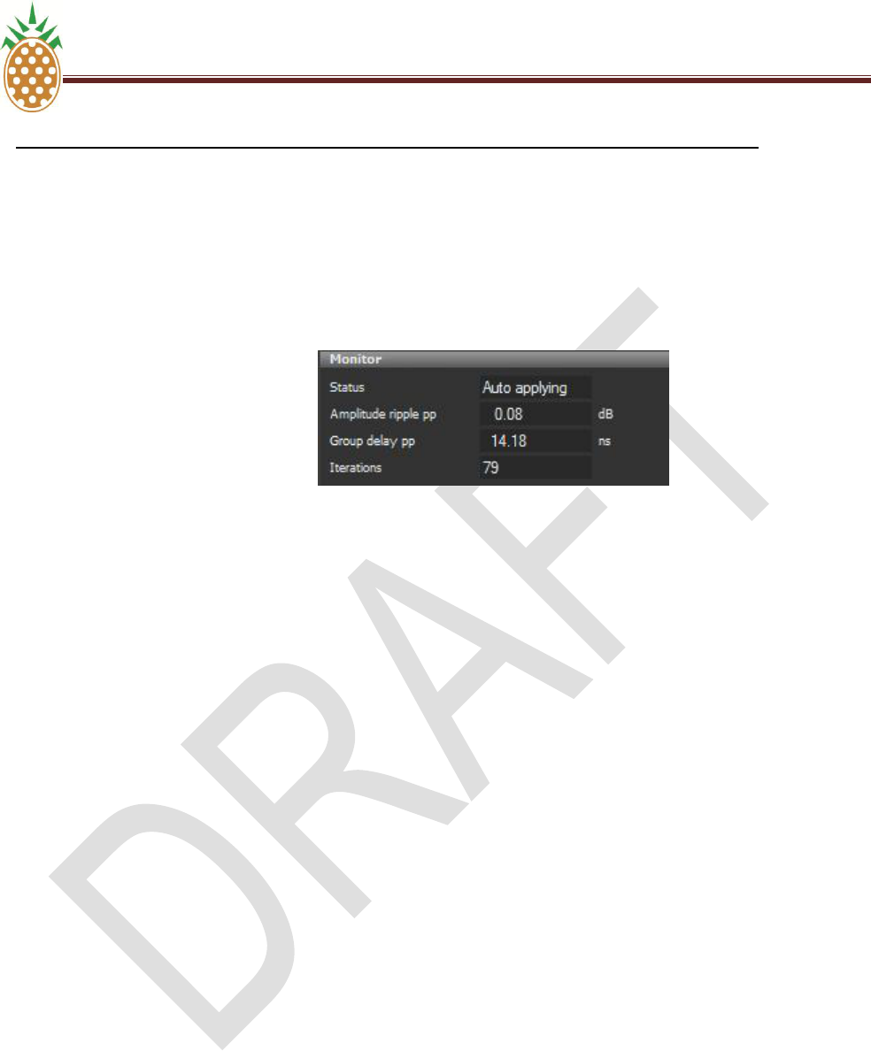
Linear Pre-Corrector Monitor Panel
The linear pre-corrector monitor panel provided information about the instantaneous performance and
operation mode.
Status: The status field shows the operational status for the linear pre-corrector system. The
possible states are:
Monitoring: indicates that the adaptive linear mode is disabled and that either the
‗Static‘ or ‗Monitoring‘ mode (refer to 3.3.1 above) is selected.
Initializing <nn%>: Indicates the progress of the initial data collection by adaptive linear
mode.
Auto applying: Indicates that correction results of the adaptive linear process are being
applied to the RF output characteristic
Not running: Adaptive linear operation is suspended by the controller system while
adaptive linear mode is selected.
Amplitude ripple pp: Read-out of the measured amplitude ripple for the signal applied to
the linear sense port. Displays the result of the last completed iteration by adaptive mode.
Displays the instantaneous performance by ‗Static‘ and ‗Monitoring‘ mode.
Group delay pp: Read-out of the measured group delay ripple for the signal applied to
the linear sense port. Displays the result of the last completed iteration by adaptive mode.
Displays the instantaneous performance by ‗Static‘ and ‗Monitoring‘ mode.
Iterations: Displays the number of adaptive linear pre-corrector iterations completed
since reset of corrector characteristic or reboot of the unit.
PINEAPPLE TECHNOLOGY, INC V.6. ADAPTIVE PRE-CORRECTOR WEB SERVICE OPERATION
DTXPRO-10U OPERATING AND SERVICE MANUAL
THE INFORMATION PROVIDED HEREIN IS PINEAPPLE TECHNOLOGY INCORPORATED PROPRIETARY INFORMATION AND
CANNOT BE COPIED OR DISTRIBUTED WITHOUT PRIOR AUTHORIZATION
51
V.6 DXDPRO-10U ADAPTIVE PRE-CORRECTOR WEB SERVICE OPERATION (Continued)
C. OPERATION OF ADAPTIVE PRE-CORRECTOR
3. LINEAR PRE-CORRECTOR CONFIGURATION
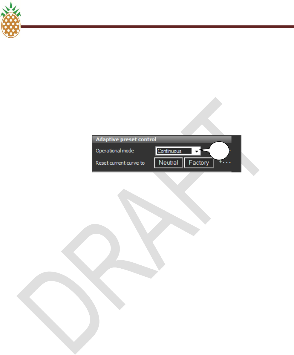
Adaptive Linear Pre-Corrector Mode Selection
The adaptive linear corrector can operate in four different modes. The required mode is selected by
opening the operational mode ‗drop-down‘ list (II).
The available modes are:
Idle: The current adaptive pre-corrector characteristic is applied to the RF output. The pre-
corrector algorithm is stopped. Changes in transmitter characteristic will not be tracked by the
pre-corrector.
Continuous: The instantaneous adaptive pre-corrector characteristic is applied to the RF
output. The pre-corrector algorithm runs continuously.
Run to target: The instantaneous adaptive pre-corrector characteristic is applied to the RF
output. The pre-corrector algorithm will run until the set threshold value is obtained for the
upper respectively the lower RE spectrum shoulder.
Auto run: The instantaneous adaptive pre-corrector characteristic is applied to the RF output.
The pre-corrector algorithm will run until the set threshold value is obtained for the upper
respectively the lower RE spectrum shoulder. The adaptive pre-corrector algorithm will be
automatically restarted in case the upper and/or lower shoulder performance subsequently
drops below the set threshold.
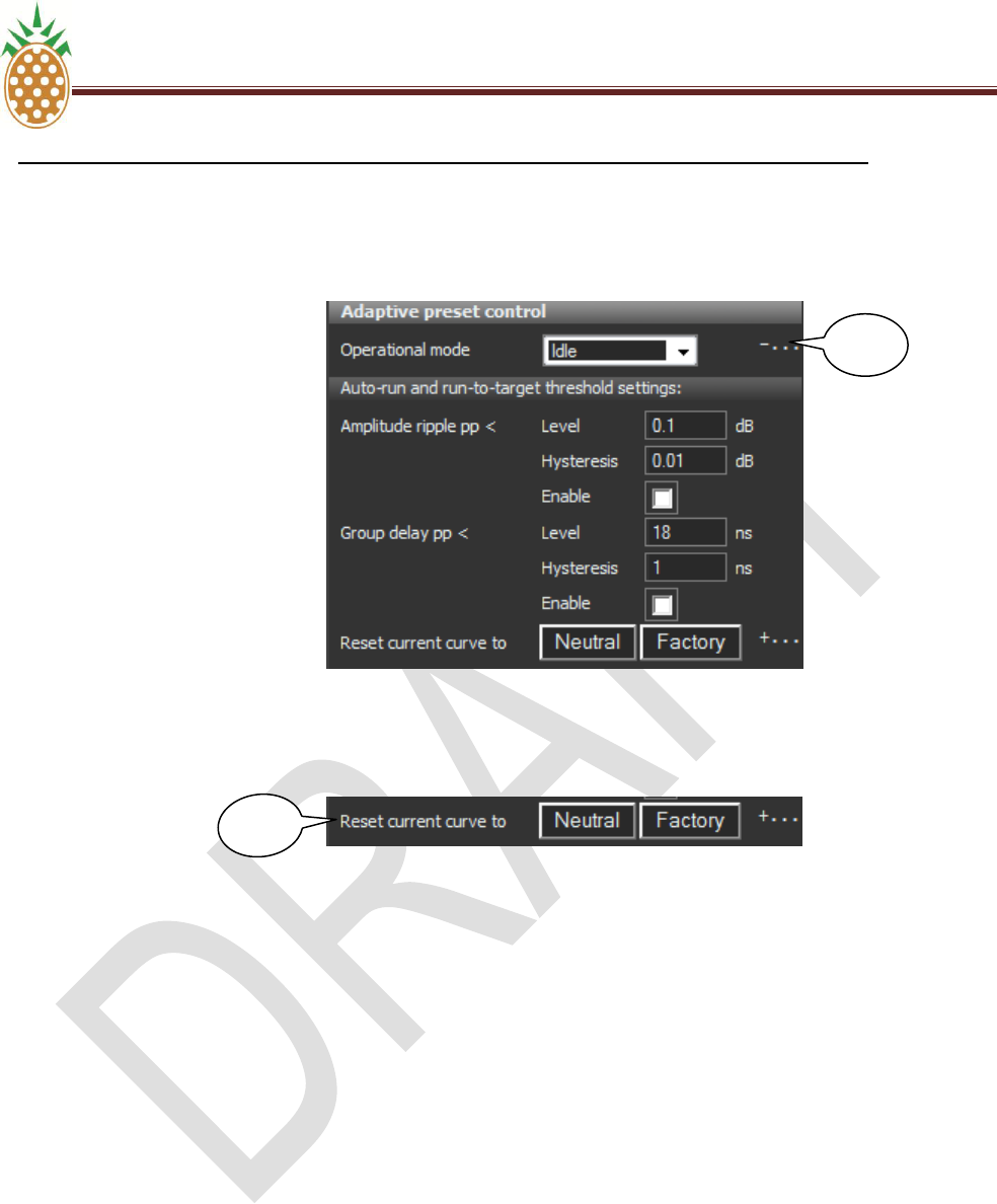
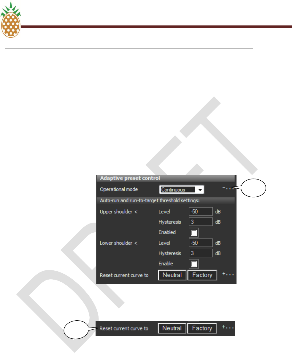
Adaptive Linear Pre-Corrector Threshold Settings
The threshold values for the adaptive pre-corrector system‘s ‗Run to target‘ and ‗Auto run’ modes are
accessed and set by expanding the ‗Auto-run and run-to-target threshold settings‘ control (III). Notice
that the respective parameter values must be ‗enabled‘ by ticking the associated enable field in order for
the parameter to have any effect on the pre-corrector algorithm.
II
PINEAPPLE TECHNOLOGY, INC V.6. ADAPTIVE PRE-CORRECTOR WEB SERVICE OPERATION
DTXPRO-10U OPERATING AND SERVICE MANUAL
THE INFORMATION PROVIDED HEREIN IS PINEAPPLE TECHNOLOGY INCORPORATED PROPRIETARY INFORMATION AND
CANNOT BE COPIED OR DISTRIBUTED WITHOUT PRIOR AUTHORIZATION
52
V.6 DXDPRO-10U ADAPTIVE PRE-CORRECTOR WEB SERVICE OPERATION (Continued)
C. OPERATION OF ADAPTIVE PRE-CORRECTOR
3. LINEAR PRE-CORRECTOR CONFIGURATION
Adaptive Linear Pre-Corrector Reset Functions
The adaptive linear pre-corrector control panel includes two controls for resetting the corrector
characteristic (IV).
There is a choice of two possible reset functions:
Neutral: The linear adaptive pre-corrector is instantly set to neutral characteristic when this
control is operated. It is recommended to start the first adaptive alignment of a new amplifier
from the neutral state.
Factory: This reset function is intended for future use. The idea is that the transmitter
manufacturer is allowed to save an adaptively derived curve characteristic and later retrieve
this specific characteristic by activating the ‗factory‘ reset.
III
IV
PINEAPPLE TECHNOLOGY, INC V.6. ADAPTIVE PRE-CORRECTOR WEB SERVICE OPERATION
DTXPRO-10U OPERATING AND SERVICE MANUAL
THE INFORMATION PROVIDED HEREIN IS PINEAPPLE TECHNOLOGY INCORPORATED PROPRIETARY INFORMATION AND
CANNOT BE COPIED OR DISTRIBUTED WITHOUT PRIOR AUTHORIZATION
53
V.6 DXDPRO-10U ADAPTIVE PRE-CORRECTOR WEB SERVICE OPERATION (Continued)
C. OPERATION OF ADAPTIVE PRE-CORRECTOR
4. NON-LINEAR PRE-CORRECTOR CONFIGURATION
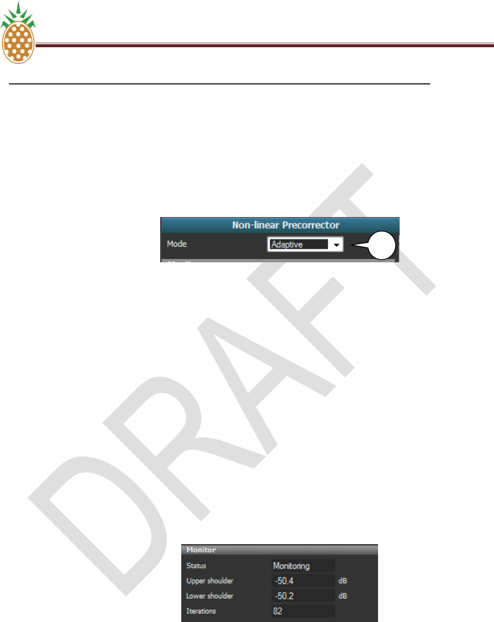
Non-Linear Pre-Corrector Mode Selection
The non-linear pre-corrector system can operate in three different modes. The required mode is selected
by opening the operational mode ‗drop-down‘ list (I).
The available modes are:
Monitoring: No non-linear pre-correction is applied to the RF output (the corrector characteristic is
neutral). The shoulder performance is measured and displayed provided that a valid feedback is
applied to the RF sense input 1.
Static: The currently loaded manual non-linear pre-corrector characteristic is applied to the RF
output. The manual pre-corrector characteristics must be generated and uploaded by means of the
PC software package IMD Buster McTwo. The curve format used by the manual pre-corrector
system is incompatible with the curves used and generated by the adaptive system.
Adaptive: The current adaptive non-linear pre-corrector characteristic is applied and maintained
according to the adaptive pre-corrector mode selected (see below for details).
Non-Linear Pre-Corrector Monitor Panel
The non-linear pre-corrector monitor panel provided information about the instantaneous performance
and operation mode.
I
I

PINEAPPLE TECHNOLOGY, INC V.6. ADAPTIVE PRE-CORRECTOR WEB SERVICE OPERATION
DTXPRO-10U OPERATING AND SERVICE MANUAL
THE INFORMATION PROVIDED HEREIN IS PINEAPPLE TECHNOLOGY INCORPORATED PROPRIETARY INFORMATION AND
CANNOT BE COPIED OR DISTRIBUTED WITHOUT PRIOR AUTHORIZATION
54
V.6 DXDPRO-10U ADAPTIVE PRE-CORRECTOR WEB SERVICE OPERATION (Continued)
C. OPERATION OF ADAPTIVE PRE-CORRECTOR
4. NON-LINEAR PRE-CORRECTOR CONFIGURATION
Status: The status field shows the operational status for the non-linear pre-corrector system.
The possible states are:
Monitoring: indicates that the adaptive mode is disabled and that either the ‗Static‘ or
‗Monitoring‘ mode (refer to 3.4.1 above) is selected.
Initializing <nn%>: Indicates the progress of the initial data collection by adaptive non-
linear mode.
Auto applying: Indicates that correction results of the adaptive non-linear process are
being applied to the RF output characteristic
Not running: Adaptive operation is suspended by the controller system while adaptive
mode is selected.
Upper shoulder: Read-out of the measured upper shoulder level for the signal applied to the
non-linear sense port. Displays the result of the last completed iteration by adaptive mode.
Displays the instantaneous performance by ‗Static‘ and ‗Monitoring‘ mode.
Lower shoulder: Read-out of the measured lower shoulder level for the signal applied to the
non-linear sense port. Displays the result of the last completed iteration by adaptive mode.
Displays the instantaneous performance by ‗Static‘ and ‗Monitoring‘ mode.
Iterations: Displays the number of adaptive non-linear pre-corrector iterations completed since
reset of corrector characteristic or reboot of the unit.
Adaptive Non-Linear Pre-Corrector Mode Selection
The adaptive Non-Linear corrector can operate in four different modes. The required mode is selected
by opening the operational mode ‗drop-down‘ list (II).
The available modes are:
Idle: The current adaptive pre-corrector characteristic is applied to the RF output. The pre-corrector
algorithm is stopped. Changes in transmitter characteristic will not be tracked by the adaptive non-
linear pre-corrector.
Continuous: The instantaneous adaptive non-linear pre-corrector characteristic is applied to the
RF output. The pre-corrector algorithm runs continuously.
Run to target: The instantaneous adaptive non-linear pre-corrector characteristic is applied to the
RF output. The pre-corrector algorithm will run until the set threshold value is obtained for the upper
respectively the lower RE spectrum shoulder.
II
PINEAPPLE TECHNOLOGY, INC V.6. ADAPTIVE PRE-CORRECTOR WEB SERVICE OPERATION
DTXPRO-10U OPERATING AND SERVICE MANUAL
THE INFORMATION PROVIDED HEREIN IS PINEAPPLE TECHNOLOGY INCORPORATED PROPRIETARY INFORMATION AND
CANNOT BE COPIED OR DISTRIBUTED WITHOUT PRIOR AUTHORIZATION
55
V.6 DXDPRO-10U ADAPTIVE PRE-CORRECTOR WEB SERVICE OPERATION (Continued)
C. OPERATION OF ADAPTIVE PRE-CORRECTOR
4. NON-LINEAR PRE-CORRECTOR CONFIGURATION
Auto run: The instantaneous adaptive non-linear pre-corrector characteristic is applied to the RF
output. The pre-corrector algorithm will run until the set threshold value is obtained for the upper
respectively the lower RF spectrum shoulder. The adaptive pre-corrector algorithm will be
automatically restarted in case the upper and/or lower shoulder performance subsequently drops
below the set threshold.
Adaptive Non-Linear Pre-Corrector Threshold Settings
The threshold values for the adaptive non-linear pre-corrector system‘s ‗Run to target‘ and ‗Auto run’
modes are accessed and set by expanding the ‗Auto-run and run-to-target threshold settings‘ control
(III). Notice that the respective parameter values must be ‗enabled‘ by ticking the associated enable field
in order for the parameter to have any effect on the pre-corrector algorithm.
Adaptive Non-Linear Pre-Corrector Reset Functions
The adaptive non- linear pre-corrector control panel includes two controls for resetting the corrector
characteristic (IV).
There is a choice of two possible reset functions:
Neutral: The non-linear adaptive pre-corrector is instantly set to neutral characteristic when this
control is operated. It is recommended to start the first adaptive alignment of a new amplifier from
the neutral state.
Factory: This reset function is intended for future use. The idea is that the transmitter
manufacturer is allowed to save an adaptively derived curve characteristic and later retrieve this
specific characteristic by activating the ‗factory‘ reset.
III
IV
PINEAPPLE TECHNOLOGY, INC V.6. ADAPTIVE PRE-CORRECTOR WEB SERVICE OPERATION
DTXPRO-10U OPERATING AND SERVICE MANUAL
THE INFORMATION PROVIDED HEREIN IS PINEAPPLE TECHNOLOGY INCORPORATED PROPRIETARY INFORMATION AND
CANNOT BE COPIED OR DISTRIBUTED WITHOUT PRIOR AUTHORIZATION
56
V.6 DXDPRO-10U ADAPTIVE PRE-CORRECTOR WEB SERVICE OPERATION (Continued)
C. OPERATION OF ADAPTIVE PRE-CORRECTOR
5. ADAPTIVE PRE-CORRECTOR STATISTICS
The ‗Adaptive‘ pre-corrector block provides various statistics concerning the adaptive process when
dragged to and expanded in the lower half of the web service page.
Elapsed time, Current iteration: Displays the time elapsed for the ongoing iteration (data
collection and analysis) for the adaptive process. The elapsed time may accumulate continuously in
the event that the sense input is invalidated and thereby preventing successful data collection and
analysis.
Last turn-around time: Displays the recorded time consumption for the last completed iteration
(data collection/analysis/curve implementation). The iteration time may typically vary from less than
10 seconds up to about one minute depending on the signal characteristic and the type of adaptive
correction running. The shortest iteration time is noted when only the non-linear adaptive pre-
corrector is running. The iteration time is increased when the adaptive linear pre-corrector process
is running.
Linear clean run: Accumulated count of the number of times the adaptive system has discarded
the collected linear data set and initiated a new collection of data. Under normal conditions this
counter is ‗0‘.
Linear bad sense count: Accumulated count of the number of times the data collection from the
linear sense port has failed for reasons other than level out of range (typically due to application of
an invalid type of spectrum on the sense port). Under normal conditions this counter is ‗0‘.
Non-Linear clean run: Accumulated count of the number of times the adaptive system has
discarded the collected non-linear data set and initiated a new collection of data. Under normal
conditions this counter is ‗0‘.
Non-Linear bad sense count: Accumulated count of the number of times the data collection from
the non-linear sense port has failed for reasons other than level out of range (typically due to
application of an invalid type of spectrum on the sense port). Under normal conditions this counter
is ‗0‘.

PINEAPPLE TECHNOLOGY, INC V.6. ADAPTIVE PRE-CORRECTOR WEB SERVICE OPERATION
DTXPRO-10U OPERATING AND SERVICE MANUAL
THE INFORMATION PROVIDED HEREIN IS PINEAPPLE TECHNOLOGY INCORPORATED PROPRIETARY INFORMATION AND
CANNOT BE COPIED OR DISTRIBUTED WITHOUT PRIOR AUTHORIZATION
57
V.6 DXDPRO-10U ADAPTIVE PRE-CORRECTOR WEB SERVICE OPERATION (Continued)
D. ECHO CANCELLING AND ADAPTIVE PRE-CORRCTION
NOTICE: THIS FEATURE IS NOT INCLUDED IN THE DXDPRO LINE PRODUCTS.
THIS IS AVAILABLE AND THE CUSTOMER SHOULD REQUEST A QUOTATION FOR
PRICE AND AVAILABILITY.
The adaptive pre-corrector option works very well in combination with the echo canceller option by ISO-
channel repeater mode with the DTXPRO-10U digital repeater unit from Pineapple Technology, Inc.
However, the echo canceller‘s ability to work effectively with high positive loop gains is dependent on already
completed linearization of the amplifier non-linearity by the adaptive pre-corrector system. Therefore, when
setting in operation a system that involves the adaptive pre-corrector as well as the echo canceller in an ISO-
channel scenario it is recommended to follow one of the following two methods:
Off-Line Linearization
The ISO-channel repeater should initially be put in operation in a configuration where feedback
between output and input is non-existent. This can be done either by feeding:
a) The input with the actual RF feed off-air while feeding the power output from the ISO-repeater
into a dummy load instead of feeding it to the transmitting antenna or
b) A locally generated RF feed into the unit from a test transmitter which is not affected by the
output of the ISO-channel repeater.
In this configuration the adaptive non-linear pre-corrector should be run until a shoulder performance of
about 40dB or better is obtained from the power amplifier. After this initial linearization of the power
amplifier the ISO-repeater can be put in operation with ‗live‘ input and output.
Gradual Loop Gain Ramp-Up
The ISO-channel repeater may alternatively be put in operation by starting at a low ‗max loop gain‘
setting for the echo canceller (for example 0dB or lower) and for each step allowing the adaptive non-
linear pre-corrector to maximize the power amplifier performance to a shoulder level of about 40dB or
better before increasing the permitted loop gain by a few dB.

PINEAPPLE TECHNOLOGY, INC V.6. ADAPTIVE PRE-CORRECTOR WEB SERVICE OPERATION
DTXPRO-10U OPERATING AND SERVICE MANUAL
THE INFORMATION PROVIDED HEREIN IS PINEAPPLE TECHNOLOGY INCORPORATED PROPRIETARY INFORMATION AND
CANNOT BE COPIED OR DISTRIBUTED WITHOUT PRIOR AUTHORIZATION
58
V.6 DXDPRO-10U ADAPTIVE PRE-CORRECTOR WEB SERVICE OPERATION (Continued)
E. APPENDIX-A CLIPPER OPERATION
1. GENERAL INFORMATION
The clipper function included with the Terrestrial Gateway product allows a controlled limitation of the
output signals peak-to-average-power-ratio (PAPR).
When the clipper is disabled the output from the Terrestrial Gateway product will exhibit a PAPR
equivalent to the inherent PAPR for the modulation format when the unit is configured/operated as a
modulator. When the unit is configured as repeater or transposer the PAPR of the processed signal may
be limited by headroom constraints in equipment prior to the repeater or transposer input. In the latter
scenario the PAPR measured on the RF output may therefore be lower than the inherent PAPR for the
modulation format in question even when the clipper is off.
Although the highest power peaks for multicarrier COFDM formats like DVB-T and MediaFLO reach a
level about 15dB over the signals average RMS power the high peaks have limited energy content. The
peaks are therefore not of immediate danger to the safe operation of a power amplifier following the
modulator output even in the normal case where the average power setting for the amplifier is not
backed off with the full PAPR relative to the peak power rating for the amplifier. The highest peaks are
simply clipped by the power amplifier. However, a performance improvement and an extension of
amplifier lifetime may be obtained if the peaks are limited to a point just below the amplifiers clip point by
the clipper function of the Terrestrial Gateway product. When the clipping is done by the Terrestrial
Gateway the following characteristics are obtained:
a) The potential short time effect on the amplifier characteristic after a power peak is eliminated; the
clipping in the Terrestrial Gateway is an instant process with no subsequent effect on the signal
processing characteristic.
b) The unavoidable noise that results from the clipping may, when the clipping takes place in the
DXDPRO modulator, be distributed as preferred by use of the ‗soft clipper‘ function (see below).
When the clipping occurs in the amplifier the noise resulting from the clipping will be distributed
evenly below, within and above the used channel. When using the clipper function of the Terrestrial
Gateway the noise may be displaced from the upper and lower sideband of the channel to minimize
disturbance of adjacent channels.
c) By clipping the signal in the Terrestrial Gateway product any possible degradation of amplifier life
time by repeated peak power stress is minimized.
2. OPERATION OF THE CLIPPER FUNCTION
Level Definition
The point of clipping relative to average power level for the signal processed can be set by dragging the
clipper block to the configuration panel. The Clipper level control can be set in the range from 12dB to
2dB. This setting refers to the baseband processing which is equivalent to a range from 15dB to 5dB for
the actual RF output (the addition to the signal of a single CW carrier, the local oscillator used in the up-
conversion process, corresponds to an increase of the PAPR by 3dB).
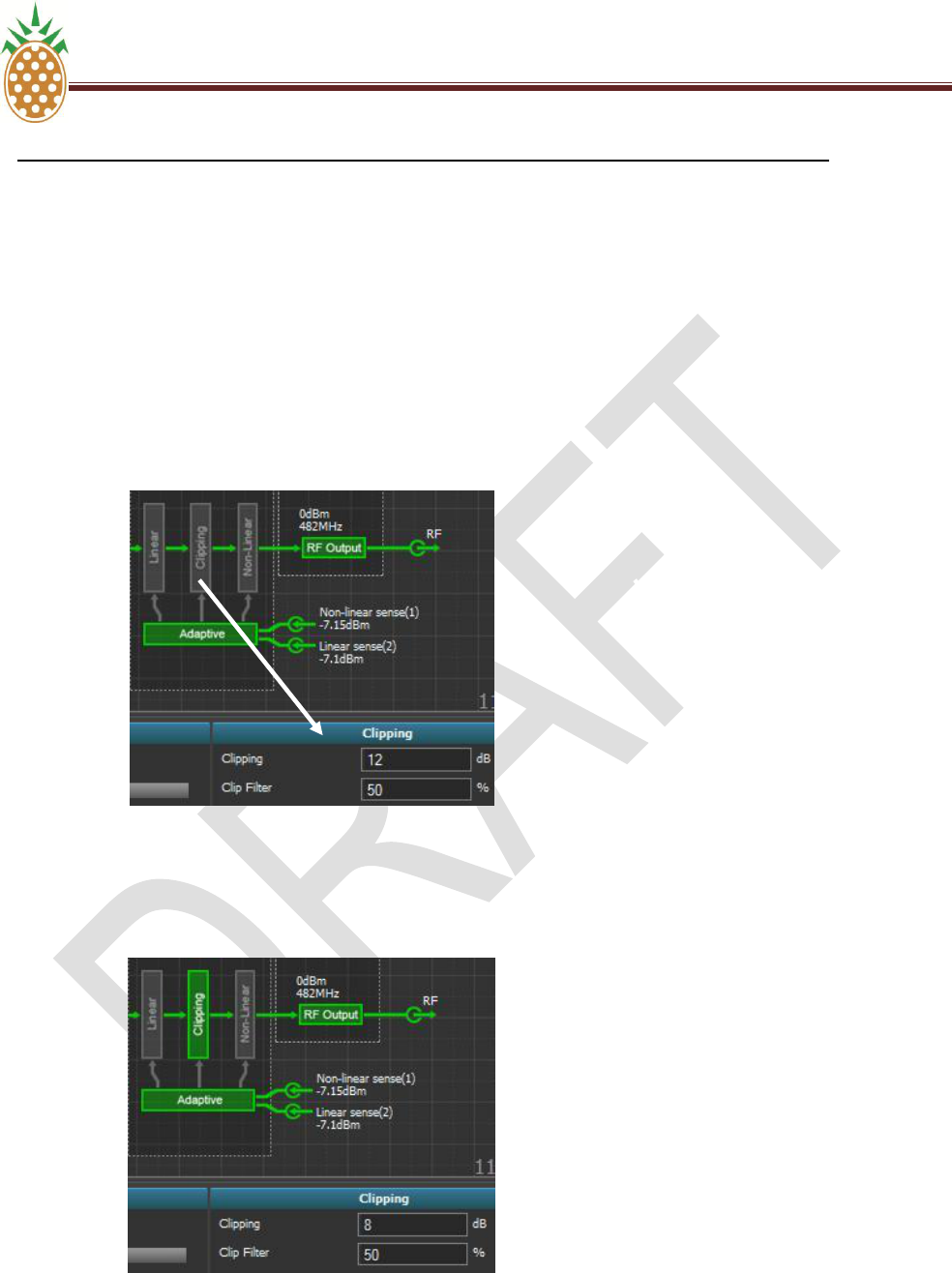
PINEAPPLE TECHNOLOGY, INC V.6. ADAPTIVE PRE-CORRECTOR WEB SERVICE OPERATION
DTXPRO-10U OPERATING AND SERVICE MANUAL
THE INFORMATION PROVIDED HEREIN IS PINEAPPLE TECHNOLOGY INCORPORATED PROPRIETARY INFORMATION AND
CANNOT BE COPIED OR DISTRIBUTED WITHOUT PRIOR AUTHORIZATION
59
V.6 DXDPRO-10U ADAPTIVE PRE-CORRECTOR WEB SERVICE OPERATION (Continued)
E. APPENDIX-A CLIPPER OPERATION
3. OPERATION OF THE CLIPPER FUNCTION
For practical reason the clipper function is considered ‗active‘ whenever the clip point is set to a value
lower than 12dB irrespective of the actual PAPR format for the modulation standard in use. When set to
the ‗active‘ state the clipper is shown in green color in the block schematic. When the clipper is inactive it
is shown in grey.
Clipper in the inactive ‘off’ state (12dB):
Clipper active (PAPR setting 8dB):
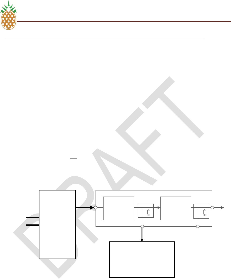
PINEAPPLE TECHNOLOGY, INC V.6. ADAPTIVE PRE-CORRECTOR WEB SERVICE OPERATION
DTXPRO-10U OPERATING AND SERVICE MANUAL
THE INFORMATION PROVIDED HEREIN IS PINEAPPLE TECHNOLOGY INCORPORATED PROPRIETARY INFORMATION AND
CANNOT BE COPIED OR DISTRIBUTED WITHOUT PRIOR AUTHORIZATION
60
V.6 DXDPRO-10U ADAPTIVE PRE-CORRECTOR WEB SERVICE OPERATION (Continued)
E. APPENDIX-A CLIPPER OPERATION
3. OPERATION OF THE CLIPPER FUNCTION
Identification of Optimal Clipper Setting
The optimal clipper setting can be identified by monitoring the output of the power amplifier using a
spectrum analyzer. The steps are as follows:
a) Ensure that the clipper initially is set to 12dB
b) Ensure that the clip filter is initially set to 0%.
c) Configure the spectrum analyzer for zero-span operation with the view focused on either the upper
or lower shoulder of the signal. A resolution of 0.1dB to 0.5dB per division is recommended.
Maintaining the original level in the form of a second trace on the analyzer (clear-write View) is
recommended for easy identification of change in the shoulder level.
d) Now, gradually increase the level of clipping applied by the Terrestrial Gateway product
(1211,51110,510……..etc). When an increase of the shoulder level observed on the
spectrum analyzer is just noticed it shows that the clipping applied by the Terrestrial Gateway is
now limiting the peaks to a point fractionally below the clip point of the amplifier itself. Although the
point will be individual from amplifier to amplifier and dependent on the actual average power level
and peak power rating of the amplifier the point is typically found around of a clipper setting
between 8 to 6 dB.
Selection of Clipper Softness (Clip Filter)
The clip filter setting may be varied according to preferences between 0% and 100%. The 100% setting
provides for maximum suppression of the clipper noise from the sidebands (lower and upper adjacent
channel) while the tradeoff is a reduction of the in-band MER performance.
PT2XXX
Power
Amplifier
Channel
Filter
RF out
Spectrum Analyzer
(Zero-span view of
shoulder for establishment
of clipping point for PA)

THE INFORMATION PROVIDED HEREIN IS PINEAPPLE TECHNOLOGY INCORPORATED PROPRIETARY INFORMATION
AND CANNOT BE COPIED OR DISTRIBUTED WITHOUT PRIOR AUTHORIZATION
61
SECTION V.7
DXDPRO-10U
BLOCK DIAGRAM
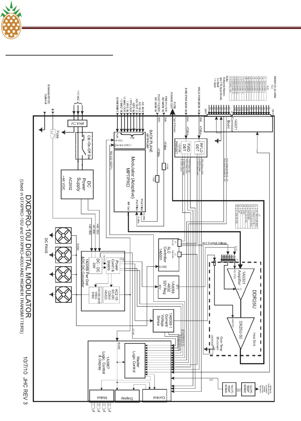
PINEAPPLE TECHNOLOGY, INC V.7. DXDPRO-10U BLOCK DIAGRAM
DTXPRO-10U OPERATING AND SERVICE MANUAL
THE INFORMATION PROVIDED HEREIN IS PINEAPPLE TECHNOLOGY INCORPORATED PROPRIETARY INFORMATION AND
CANNOT BE COPIED OR DISTRIBUTED WITHOUT PRIOR AUTHORIZATION
62
V.7 DXDPRO-10U BLOCK DIAGRAM

THE INFORMATION PROVIDED HEREIN IS PINEAPPLE TECHNOLOGY INCORPORATED PROPRIETARY INFORMATION AND
CANNOT BE COPIED OR DISTRIBUTED WITHOUT PRIOR AUTHORIZATION
63
SECTION VI
DTXPRO-10U
INSTALLATION
PROCEDURES

PINEAPPLE TECHNOLOGY, INC VI. DTXPRO-10U INSTALLATION PROCEDURES
DTXPRO-10U OPERATING AND SERVICE MANUAL
THE INFORMATION PROVIDED HEREIN IS PINEAPPLE TECHNOLOGY INCORPORATED PROPRIETARY INFORMATION AND
CANNOT BE COPIED OR DISTRIBUTED WITHOUT PRIOR AUTHORIZATION
64
VI. DTXPRO-10U INSTALLATION PROCEDURES
To ensure long and reliable trouble-free service from the DTXPRO-10U transmitter, the following
steps for installation are recommended:
1. MECHANICAL INSTALLATION: The DTXPRO-10U was designed to be installed in a building
protected from the weather. The building should have a hard-surface floor such as concrete with
a moisture barrier. This barrier could be pressure-treated wood sub flooring which could be
anchored to the concrete and to the transmitter to make the installation earthquake resistant.
Allow a minimum of three feet around the transmitter cabinet for service access.. Provisions for
air inlet and exhaust from the room must allow air flow with minimal obstruction. In the event
that the room temperature exceeds 35º Celsius (95º F), cooling air must be provided so that the
room temperature will not exceed 35 degrees Celsius under worse case conditions.
Notice: This equipment is HEAVY and must be handled by professional movers with proper
equipment. Any damage caused by the installers is not covered under warranty. Check to
ensure the installing crews have proper insurance coverage.
2. GROUNDING: Transmitter grounding is VERY IMPORTANT and must be done correctly for
safety and operational reasons. The single point grounding technique can be effective to protect
multiple pieces of equipment installed inside an equipment rack cabinet. Treat the rack the
same as you would a building, a copper bus bar has been mounted inside the cabinet to act as
both an entrance panel and reference ground for all conductors entering and leaving the rack. It
is recommended the customer install an AC surge protector at this point in shunt to ground, and
install a series impedance between the panel and the equipment. The chassis of each piece of
equipment has been bonded to this buss bar with a single copper braid or strap. Redundant
ground connections by means of the AC cable and the shields of audio cables should be
avoided when possible. Finally, connect the rack‘s access panel to the building reference
ground using a heavy gauge wire such as #2 AWG stranded copper or solid copper buss one
(1) inch wide by 1/8 inch thick for connections. The bonding between the transmitter and the
ground rods must be good quality and protected from corrosion. The ground wires should run
over the floor and be connected to the ground rods located outside the building. The wire should
not go thru the concrete floor but over and around it.
3. AC WIRING: AC voltage for the transmitter is normally 110 VAC. Connections to the AC Main
should be made as follows:
--- RED and BLACK wires are connected to the 110 VAC.
--- WHITE wire is connected to NEUTRAL.
---GREEN wire is connected to SAFETY GROUND.
NOTICE: All wiring of this type must be done by a QUALIFIED ELECTRICIAN and must
conform to LOCAL and NATIONAL wiring CODES.
Consult with your electrician to ensure that the proper breaker size is selected for the main
circuit.

PINEAPPLE TECHNOLOGY, INC VI. DTXPRO-10U INSTALLATION PROCEDURES
DTXPRO-10U OPERATING AND SERVICE MANUAL
THE INFORMATION PROVIDED HEREIN IS PINEAPPLE TECHNOLOGY INCORPORATED PROPRIETARY INFORMATION AND
CANNOT BE COPIED OR DISTRIBUTED WITHOUT PRIOR AUTHORIZATION
65
VI. DTXPRO-10U INSTALLATION PROCEDURE (Continued)
4. ANTENNA CONNECTION: The transmitter is equipped with a type N connector located at the
rear of the rack. The RF ATSC Compliant Mask Filter and output Directional Coupler(s) are
provided with the transmitter and are to be located and mounted at the customer discretion.
Pineapple Technology recommends the filter be securely mounted above the transmitter cabinet
but not in a position that could inhibit air circulation from the top of the cabinet. The directional
coupler is usually mounted on the output of the mask filter convenient for connection to the
station antenna transmission line. Two cables have been provided for connection between the
output directional coupler monitor ports and the DXDPRO-10U Modulator. Conditions vary from
site to site so some engineering may be required to ensure that the antenna is receiving the
correct amount of power to comply with FCC licenses and to ensure safety from lightning, etc.

THE INFORMATION PROVIDED HEREIN IS PINEAPPLE TECHNOLOGY INCORPORATED PROPRIETARY INFORMATION AND
CANNOT BE COPIED OR DISTRIBUTED WITHOUT PRIOR AUTHORIZATION
66
SECTION VII
DTXPRO-10U
SERVICE
REQUIREMENTS

PINEAPPLE TECHNOLOGY, INC VII. DTXPRO-10U SERVICE REQUIRMENTS
DTXPRO-10U OPERATING AND SERVICE MANUAL
THE INFORMATION PROVIDED HEREIN IS PINEAPPLE TECHNOLOGY INCORPORATED PROPRIETARY INFORMATION AND
CANNOT BE COPIED OR DISTRIBUTED WITHOUT PRIOR AUTHORIZATION
67
VII. DTXPRO-10U SERVICE REQUIREMENTS
Routine maintenance of the DTXPRO-10U consists of cleaning or replacing the air inlet filter. In
normal operating environments this should be done once a month or more often in dusty
environments. Cleaning should be done with a light detergent. Rinse and dry the filter carefully
before installing. Any detergent residue could damage components in the modulator. For this
reason, the first option should be to replace the filter with a new one (PTI Part Number 990202)
The following data should be recorded in the station log. This information should be compared to
previous test recordings to insure normal operations.
1. DC SUPPLY VOLTAGE
2. DC CURRENT
3. OUTPUT POWER PERCENT (%)
4. REFLECTED POWER PERCENT (%)
5. HEAT SINK TEMPERATURE IN DEGREES CELCIUS
Under normal operating conditions is the performance of the adaptive linear and non- linear
correction performance should be checked. This can be done remotely if the unit is connected
via Ethernet or on each visit to the site. Adaptive linear correction is normally placed in the idle
mode once the correction is complete. If so, the corrector can be placed in AUTO RUN for a
while to optimize the correction and then returned to the idle mode.

THE INFORMATION PROVIDED HEREIN IS PINEAPPLE TECHNOLOGY INCORPORATED PROPRIETARY INFORMATION
AND CANNOT BE COPIED OR DISTRIBUTED WITHOUT PRIOR AUTHORIZATION
68
SECTION VIII
DTXPRO-10U
WARRANTY

IIPINEAPPLE TECHNOLOGY, INC VIII. DTXPRO-10U WARRANTY
DTXPRO-10U OPERATING AND SERVICE MANUAL
THE INFORMATION PROVIDED HEREIN IS PINEAPPLE TECHNOLOGY INCORPORATED PROPRIETARY INFORMATION AND
CANNOT BE COPIED OR DISTRIBUTED WITHOUT PRIOR AUTHORIZATION
69
VIII. DTXPRO-10U WARRANTY
The WARRANTY provided by Pineapple Technology, Inc., on this transmitter is detailed below. It
should be noted that some of the equipment sub-systems have warranty coverage by the original
manufacture that differs from the standard warranty provided by PTI Warranty details on
equipment falling into this category may be found in the Manufacturers instruction manual provided
with the transmitter. In all cases, replacement units of this equipment are normally in stock at PTI
for quick turn service support to our customers during the PTI Standard Warranty period.
STANDARD WARRANTY
Seller warrants that each product sold by it is free of defects in materials and workmanship.
Seller's obligation under said warranty continues for a period of one (1) year from date of shipment.
Repairs or replacement of defective parts shall be the sole and exclusive remedy under warranty,
at Seller‘s option, provided that Seller may, as an alternative, elect to refund an equitable portion of
the purchase price of the product. THIS WARRANTY IS EXPRESSLY IN LIEU OF AND
EXCLUDES ALL OTHER EXPRESS OR IMPLIED WARRANTIES, INCLUDING BUT NOT
LIMITED TO WARANTIES OF FITNESS FOR A PARTICULAR PURPOSE, USE, OR
APPLICATION, AND ALL OTHER OBLIGATIONS OR LIABILITIES ON THE PART OF THE
SELLER, UNLESS SUCH OTHER WARRANTIES OBLIGATIONS OR LIABILITIES ARE
EXPRESSLY AGREED TO IN WRITING BY SELLER.
WARRANTY REPLACEMENT AND REPAIRS
All claims under warranty must be made promptly after occurrence of circumstances giving rise to
thereto and must be received within the applicable warranty period by seller or its authorized
representatives. Such claims must be documented on a PTI* Field Failure Report with a full
description of the circumstances giving rise to the claim. Before any products are returned for
repair and/or adjustment, written authorization from Seller or its authorized representative for the
return and instructions as to how and where these products should be shipped must be obtained.
This is to include a Return Authorization (RA) number provided by the Seller or its authorized
representative, this must accompany ALL returns. Any product returned to the Seller for the
examination shall be sent prepaid via the means of transportation indicated as acceptable by
Seller. Seller reserves the right to reject any warranty claim not promptly reported and any claim on
any item that has been altered, i.e. circuit modifications, components removed, or has been
shipped by non acceptable means of transportation . When a product has been returned for
examination and inspection, or for any other reason, customer shall be responsible for all damage
resulting from improper packaging or handling, and for loss in transit, notwithstanding any defect or
nonconformity in the product. In all cases the Seller has sole responsibility for determining the
cause and nature of the failure, and the Seller's determination with regard thereto shall be final. If it
is found that Seller's product has been returned without cause and is still serviceable, customer will
be notified and the product returned at customer‘s expense. In addition, a charge for testing and
examination may, in Seller‘s sole discretion, be made on products so returned.
A Field Failure Report is included at the end of this manual - Additional Field Failure
Reports can be obtained by calling Pineapple Technology, Inc. at (916) 652-1116 or you
may download one from our website at www.ptibroadcast.com in the Warranty section.