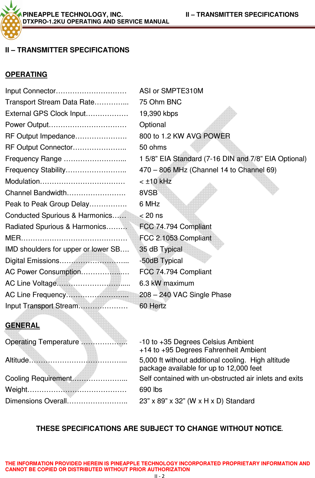
Pineapple Technology DTXPRO1200U 1.2 KW DTV TRANSMITTER User Manual Manual 1
Pineapple Technology, Inc. 1.2 KW DTV TRANSMITTER Manual 1
UserManual.wiki
>
Pineapple Technology
>
DTXPRO1200U User Manual
>
Manual Section 1
Contents
1.
Manual Section 1
2.
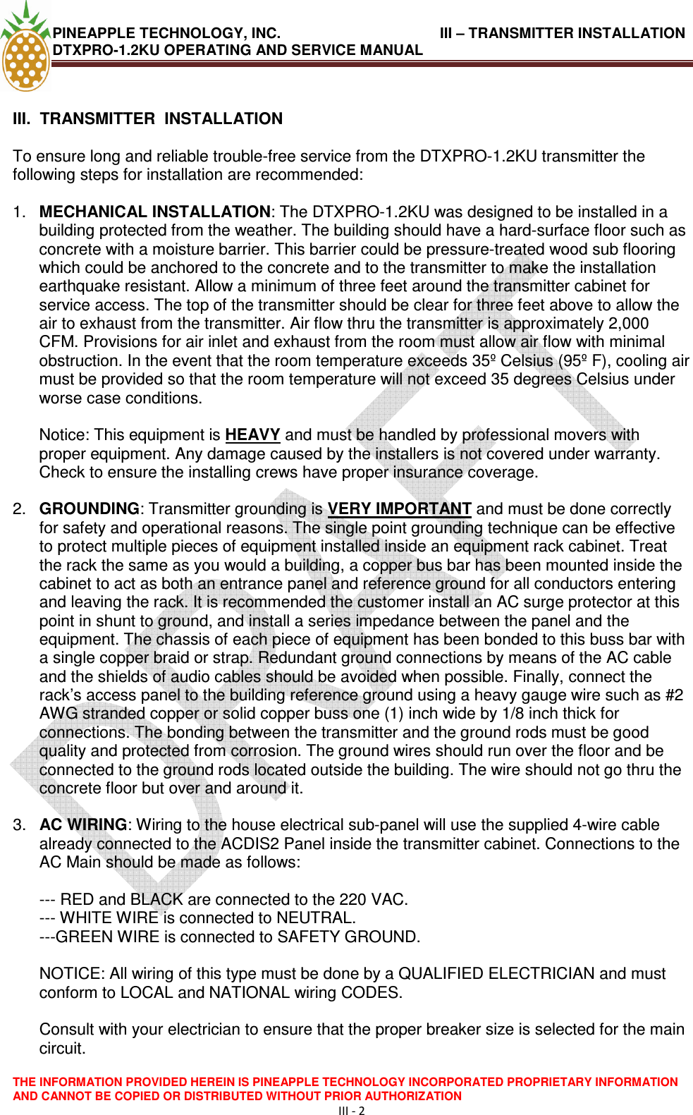
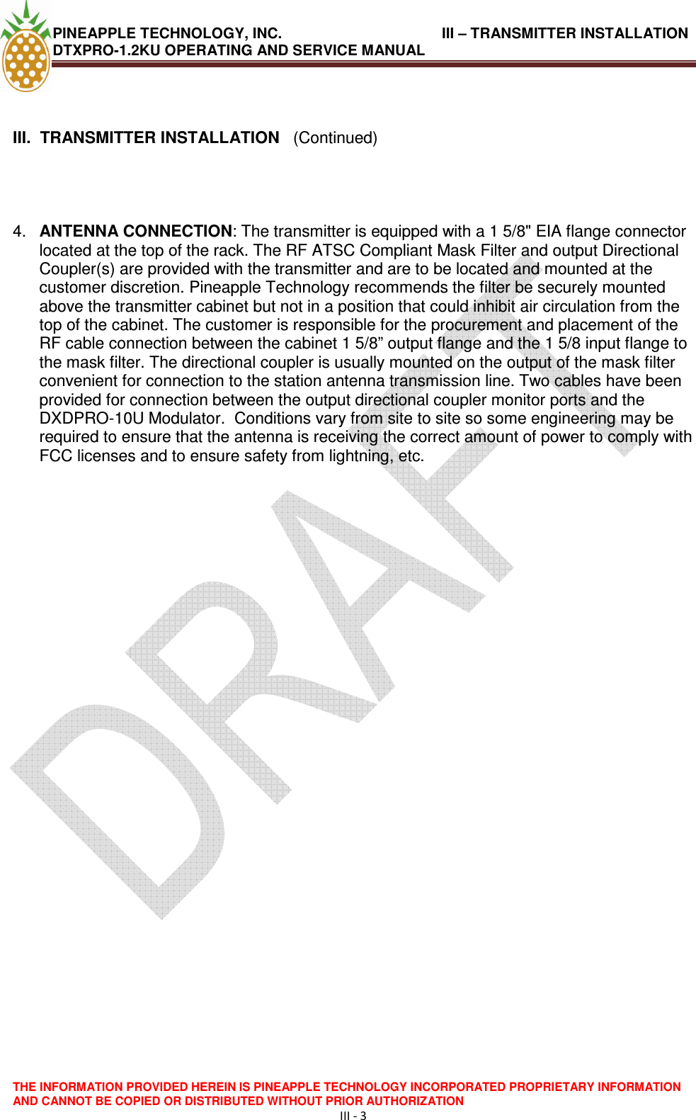
Manual Section 2
Manual Section 1
Navigation menu
Upload a User Manual
Namespaces
Wiki Guide
HTML
PDF
Info
Views
User Manual
Discussion / Help
Navigation