Pineapple Technology DTXPRO2300U 2.3KW DTV TRANSMITTER User Manual User s Manual
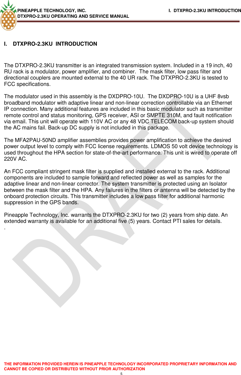
Pineapple Technology, Inc. 2.3KW DTV TRANSMITTER User s Manual
UserManual.wiki
>
Pineapple Technology
>
DTXPRO2300U User Manual
User's Manual
Navigation menu
Upload a User Manual
Namespaces
Wiki Guide
HTML
PDF
Info
Views
User Manual
Discussion / Help
Navigation

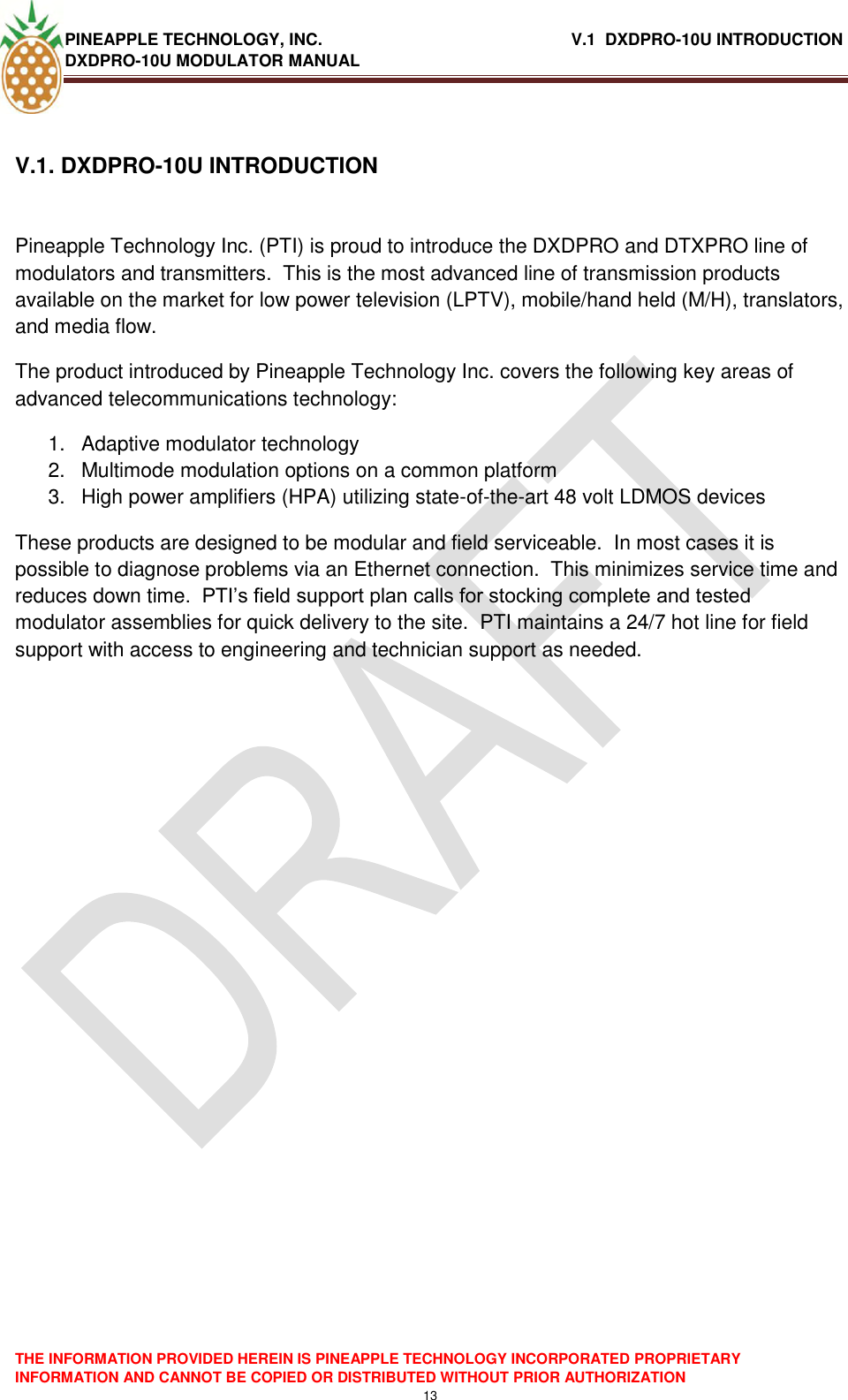
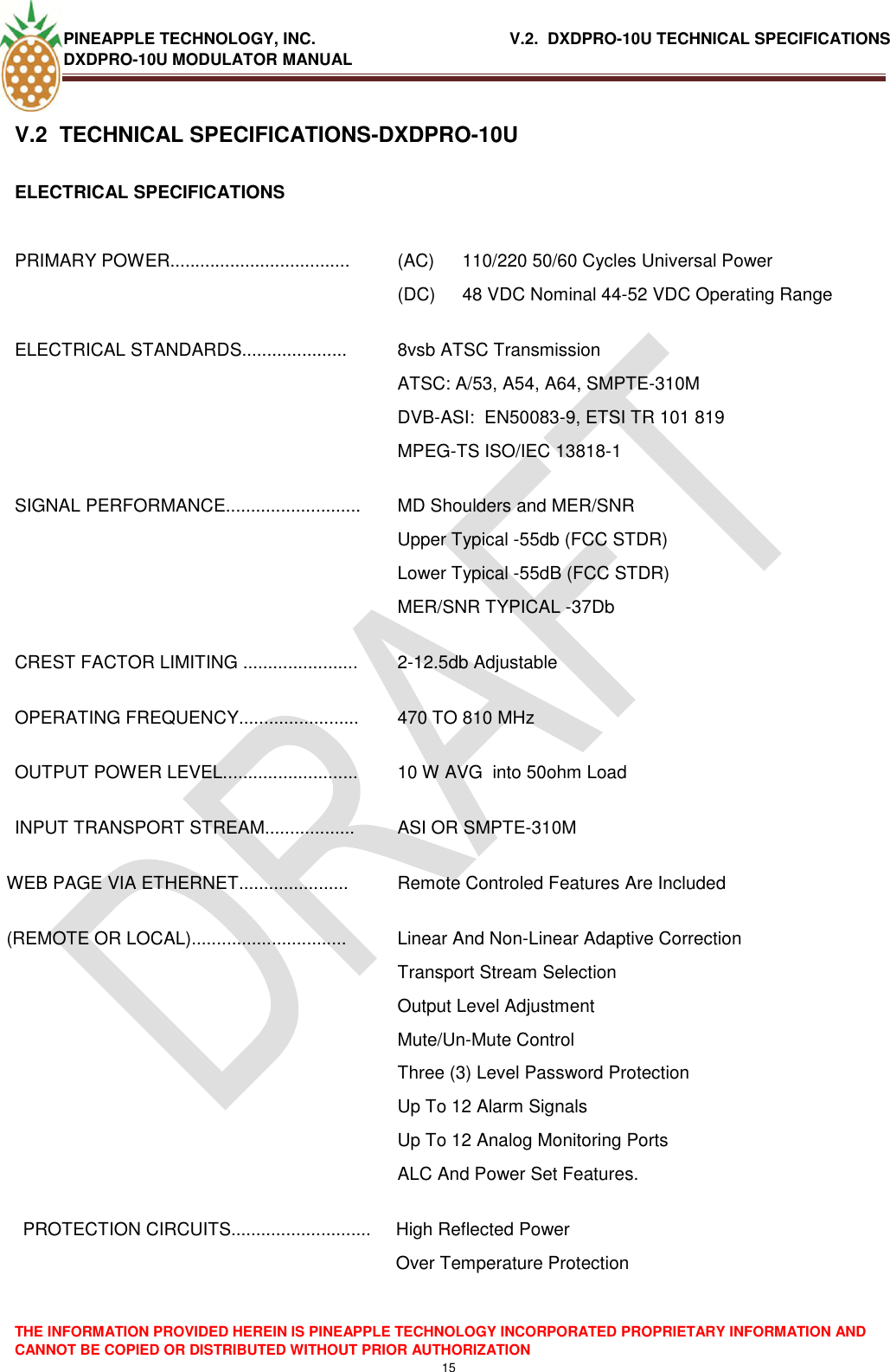
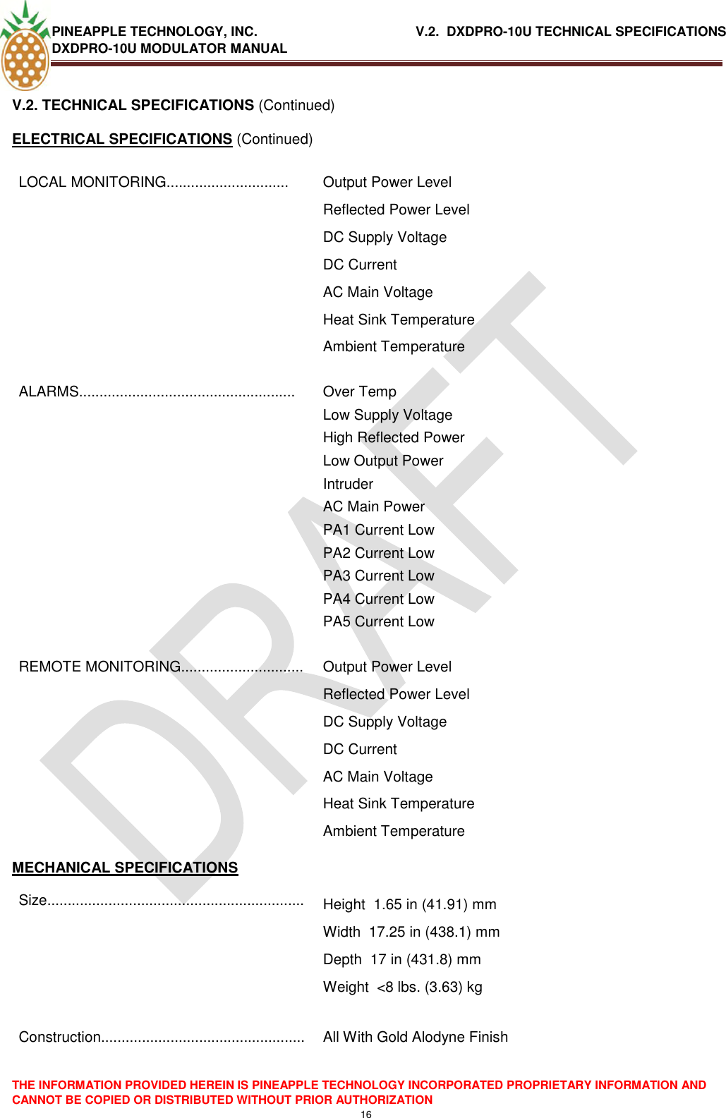
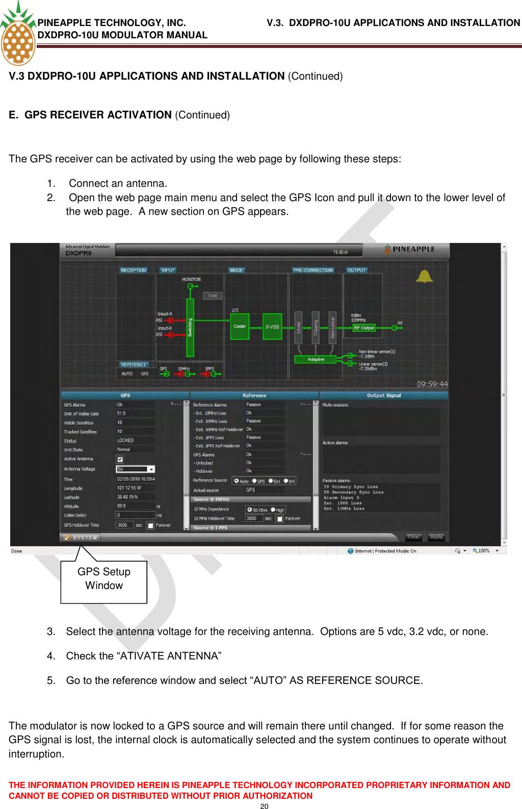
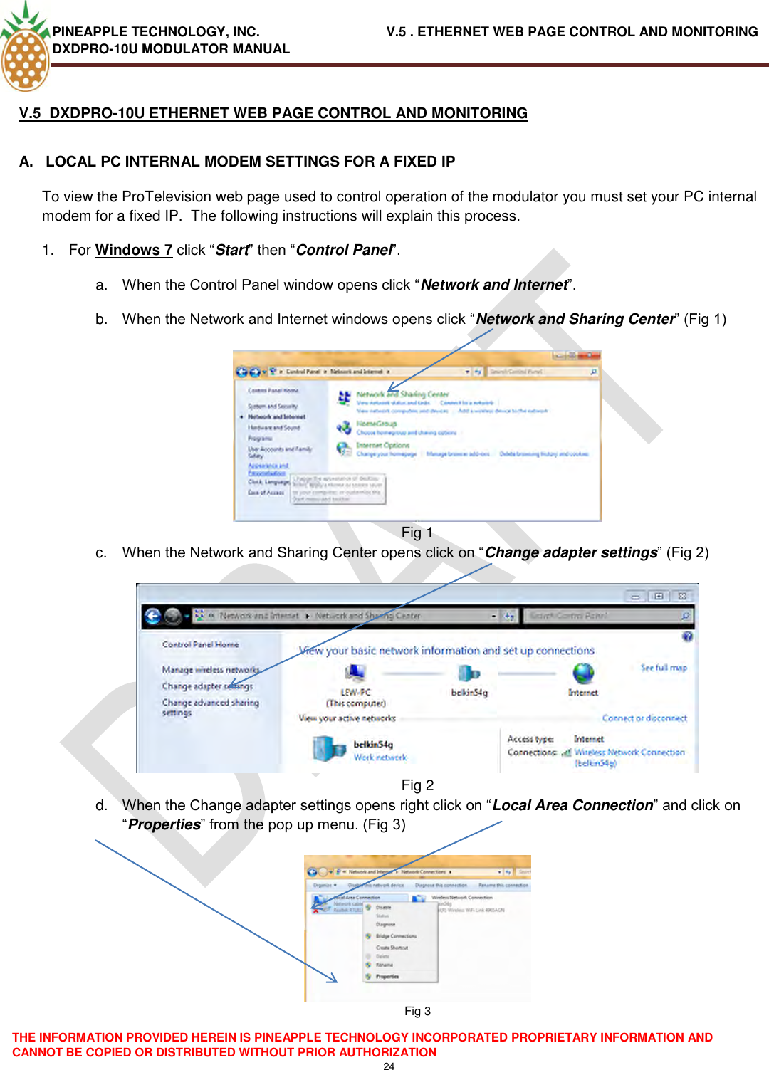
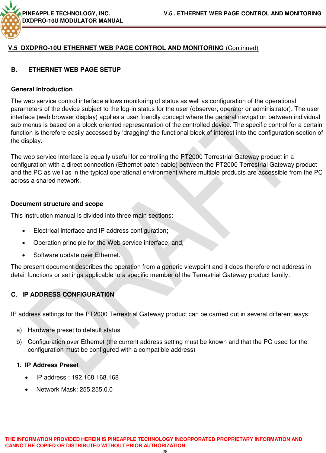
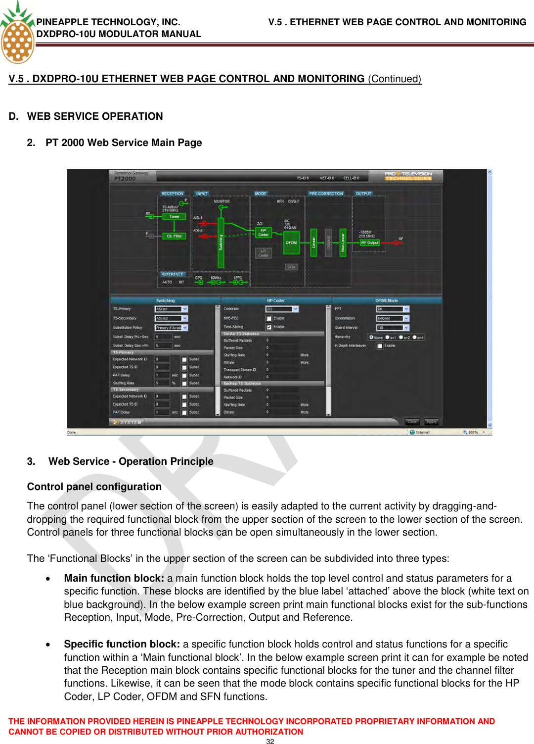
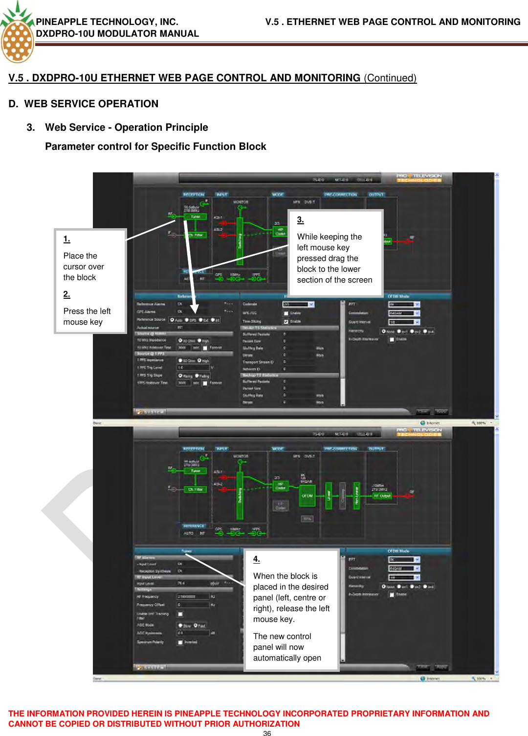
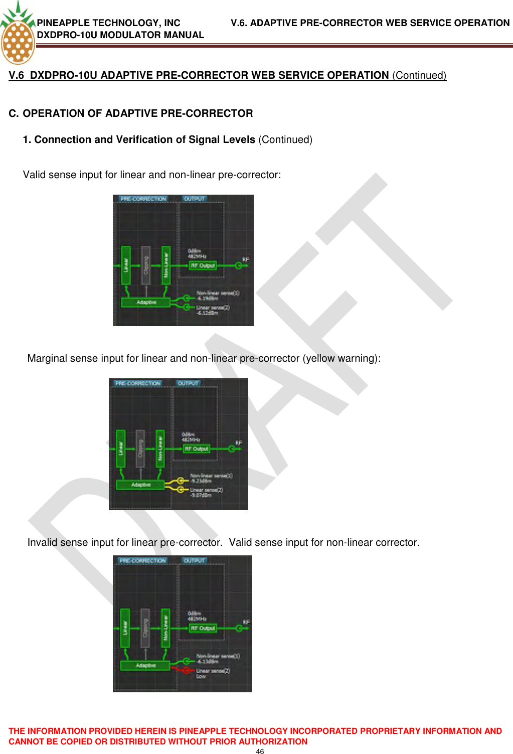
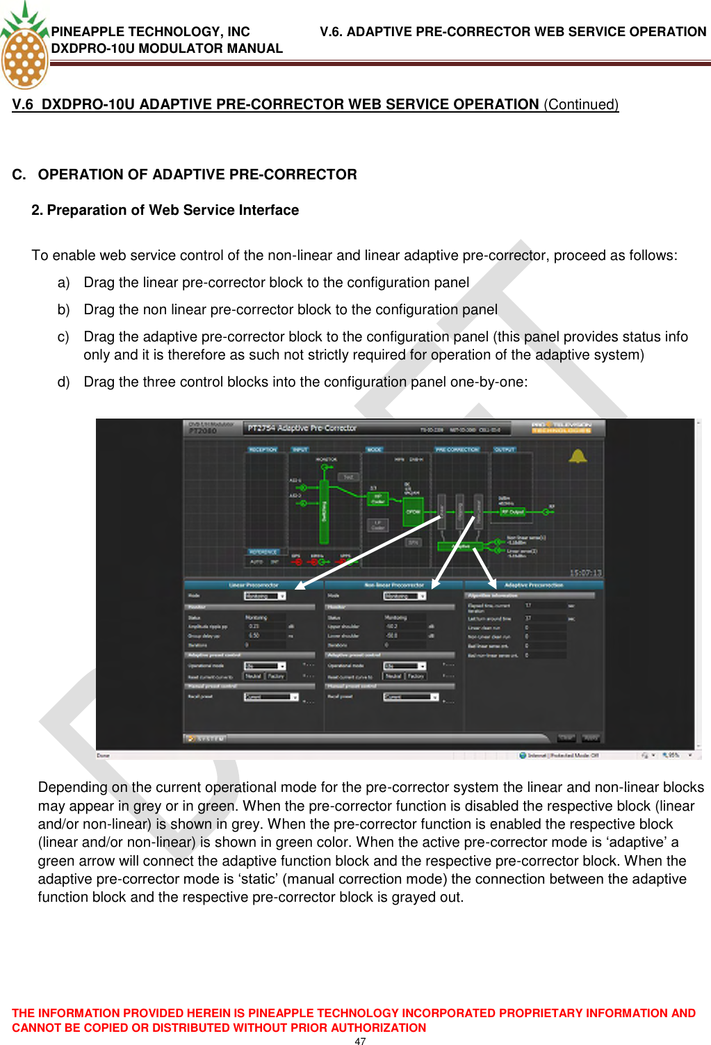
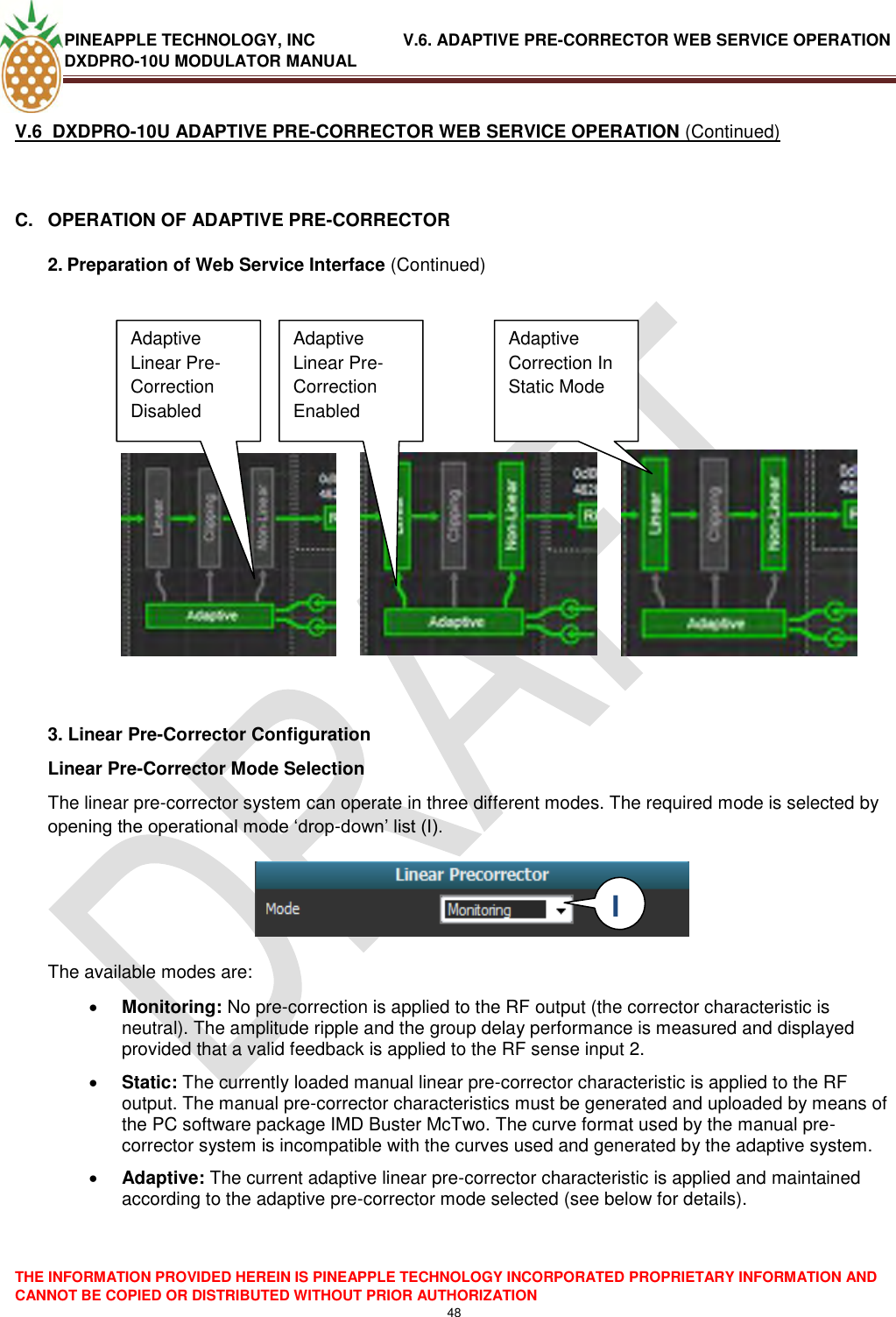
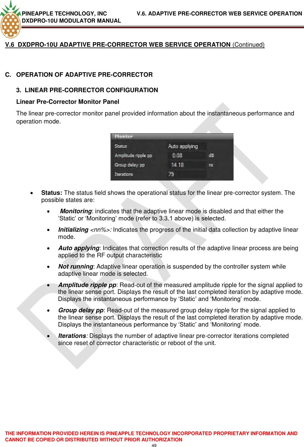
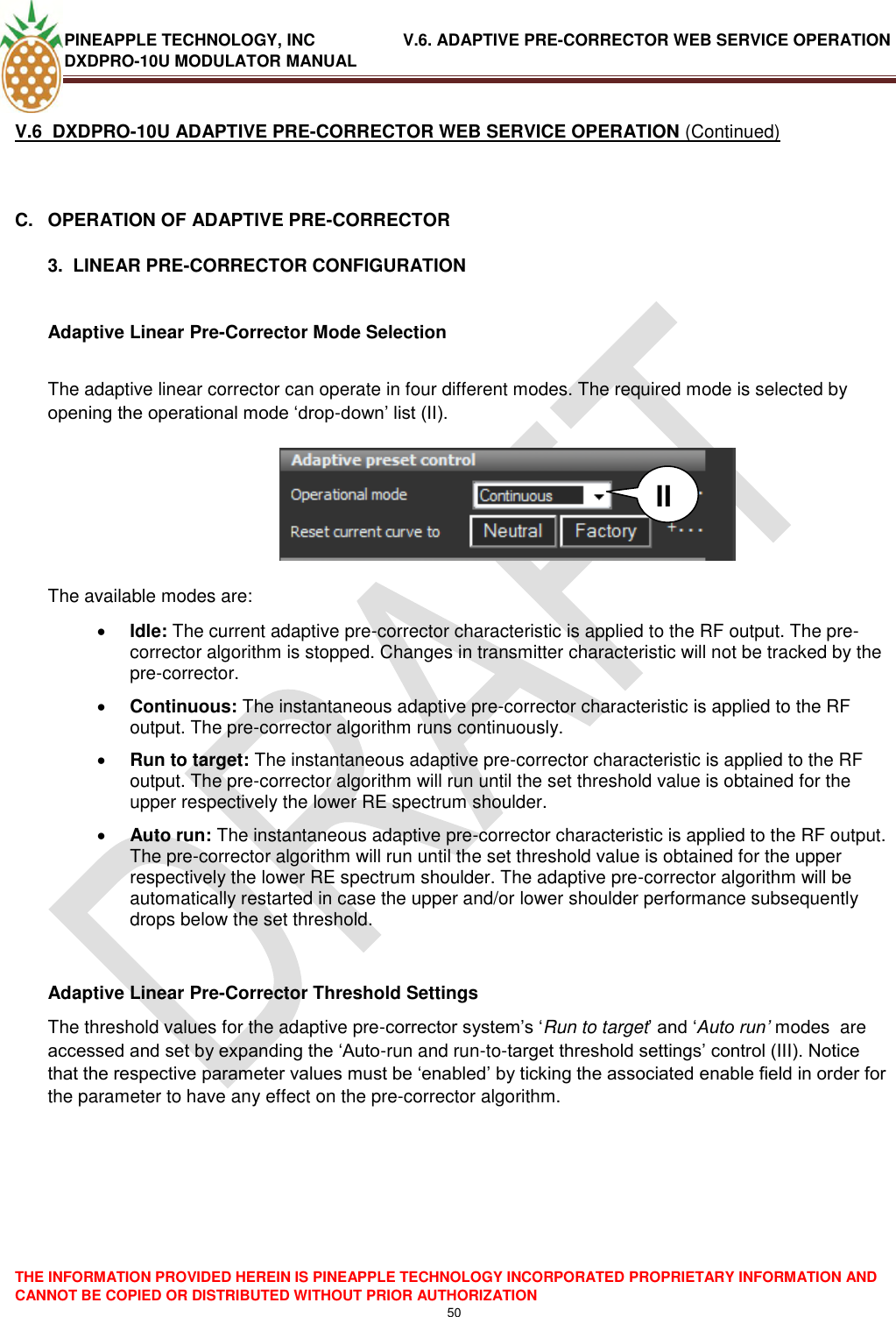
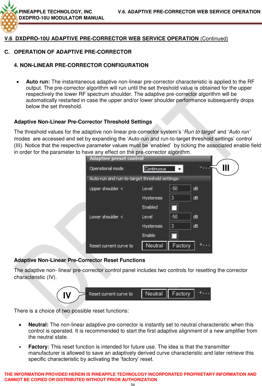
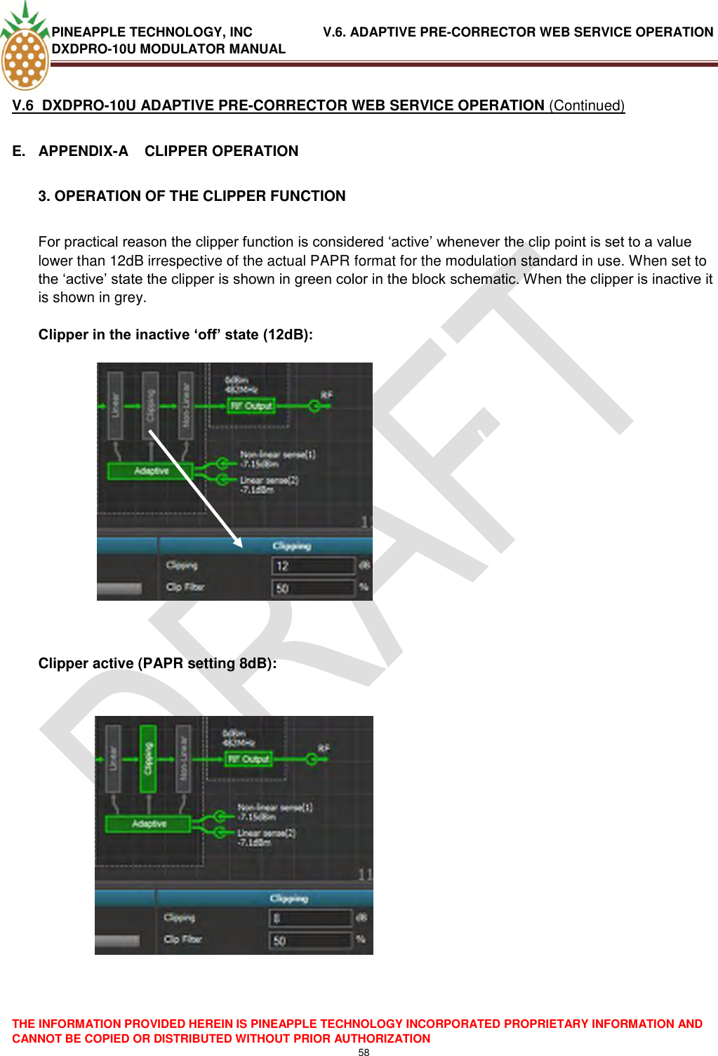
![PINEAPPLE TECHNOLOGY, INC. V.5 . ETHERNET WEB PAGE CONTROL AND MONITORING DXDPRO-10U MODULATOR MANUAL THE INFORMATION PROVIDED HEREIN IS PINEAPPLE TECHNOLOGY INCORPORATED PROPRIETARY INFORMATION AND CANNOT BE COPIED OR DISTRIBUTED WITHOUT PRIOR AUTHORIZATION 38 V.5 . DXDPRO-10U ETHERNET WEB PAGE CONTROL AND MONITORING (Continued) D. WEB SERVICE OPERATION 3. Web Service - Operation Principle Parameter Control For Interface Point Access To System Parameters A number of system oriented parameters can be accessed by left-clicking the [System] button located in the lower-left corner of the web page. To access a specific system (for example saving or loading a device preset) proceed as follows: 1. Left click the [System] button. A menu including the various choices will now open up above the [system] button. 2. From the menu select the required function (for example ‗Preset‘ management) by left-clicking the point in the menu. 3. The corresponding control panel will now open up in the lower section of the screen in place of the three regular control panels. 4. When the setting of interest has been verified/changed as required the ‗system‘ control panel is closed again by left clicking the [X] in the top-right corner of the panel. 4. When the Interface point is placed in the desired panel (left, centre or right), release the left mouse key. The new control panel will now automatically open](https://usermanual.wiki/Pineapple-Technology/DTXPRO2300U/User-Guide-1414764-Page-40.png)
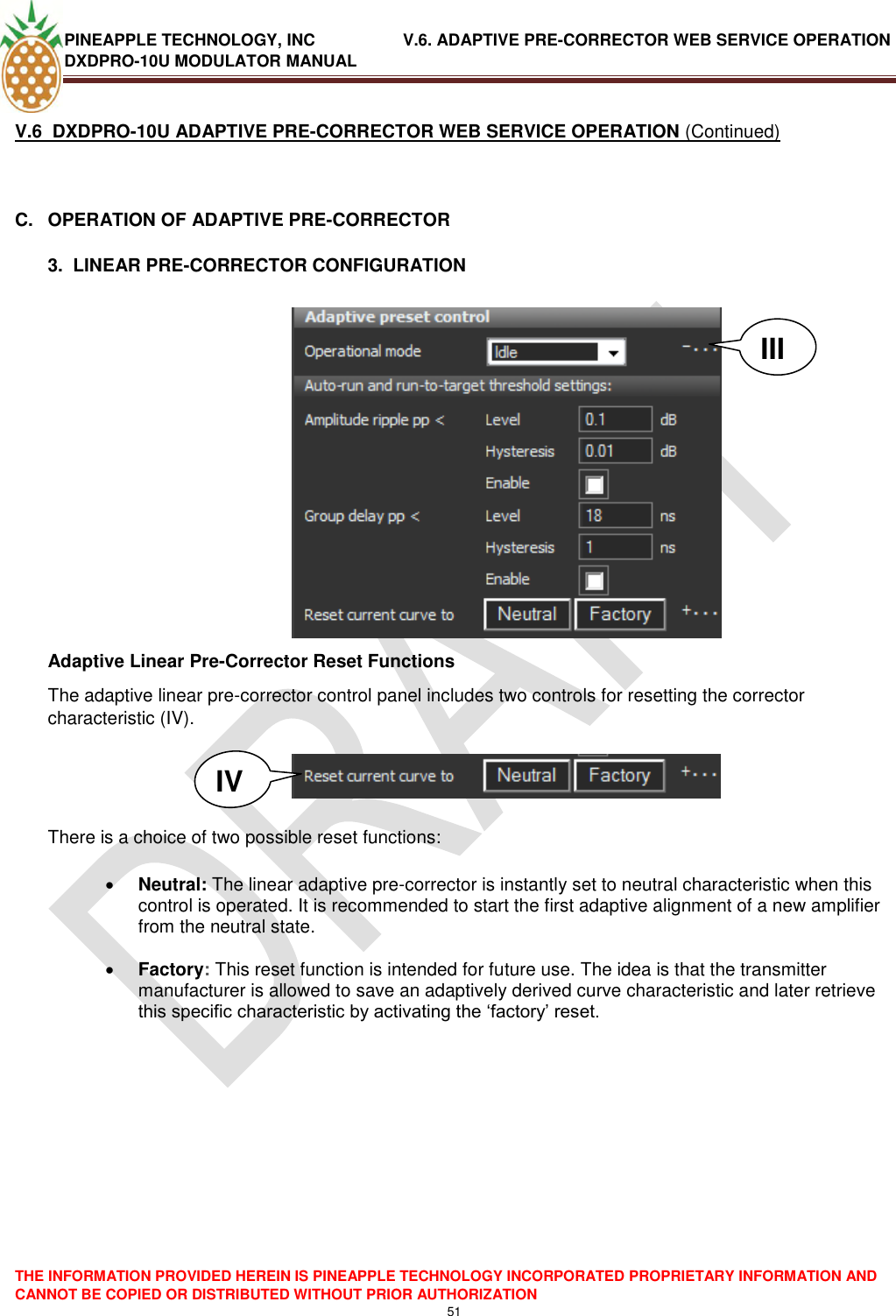
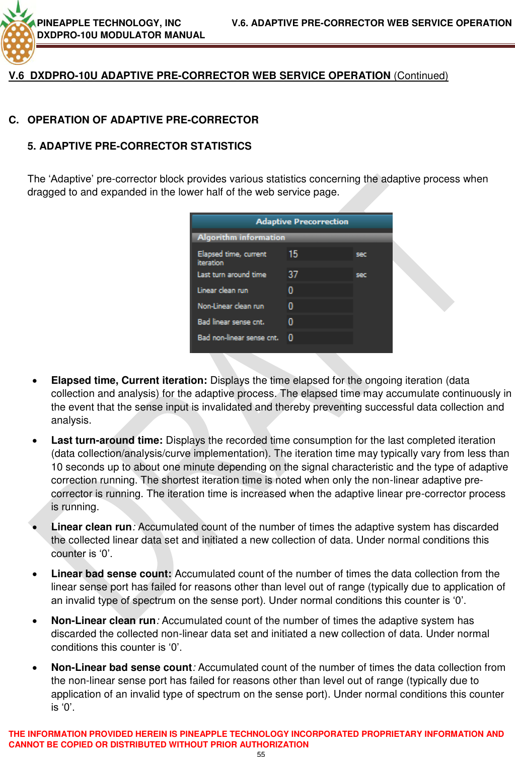
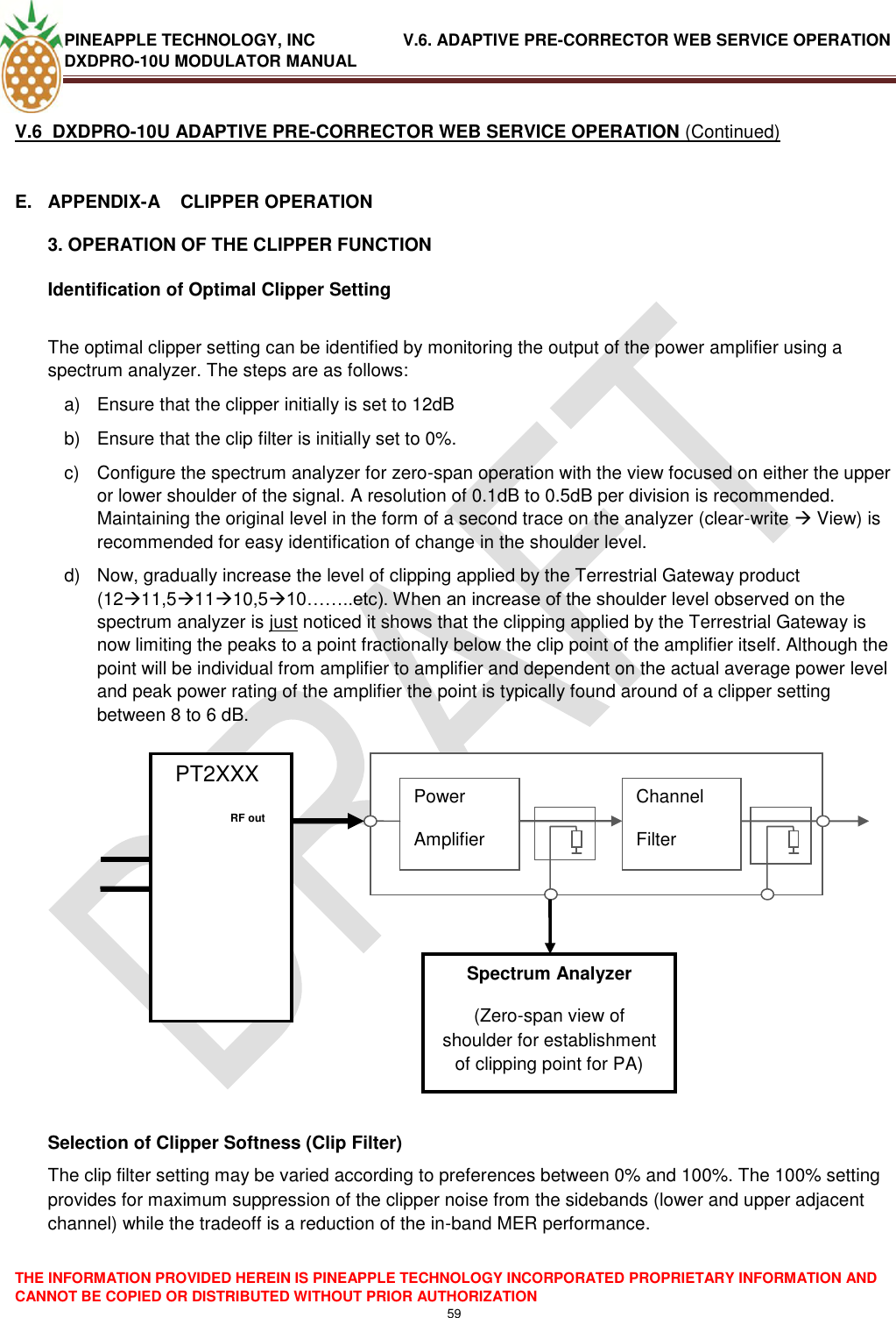
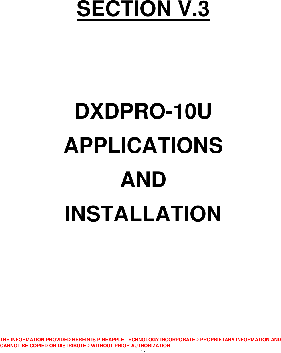
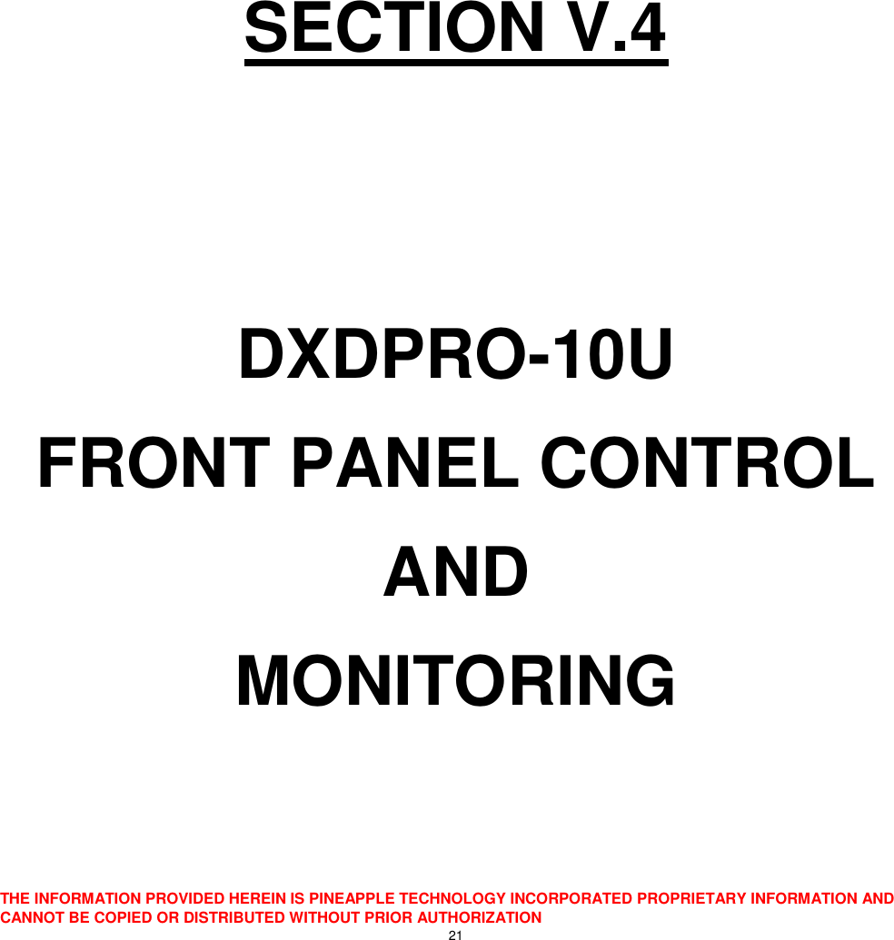
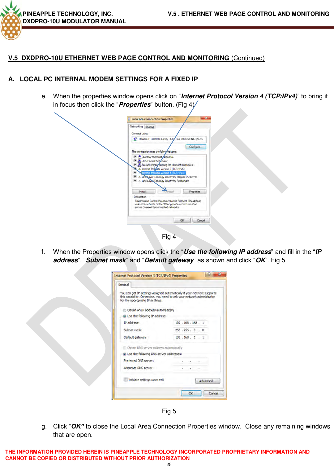
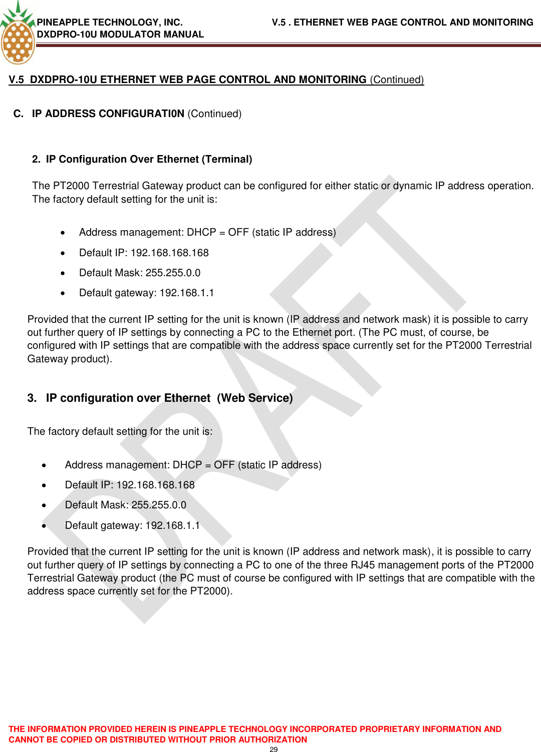
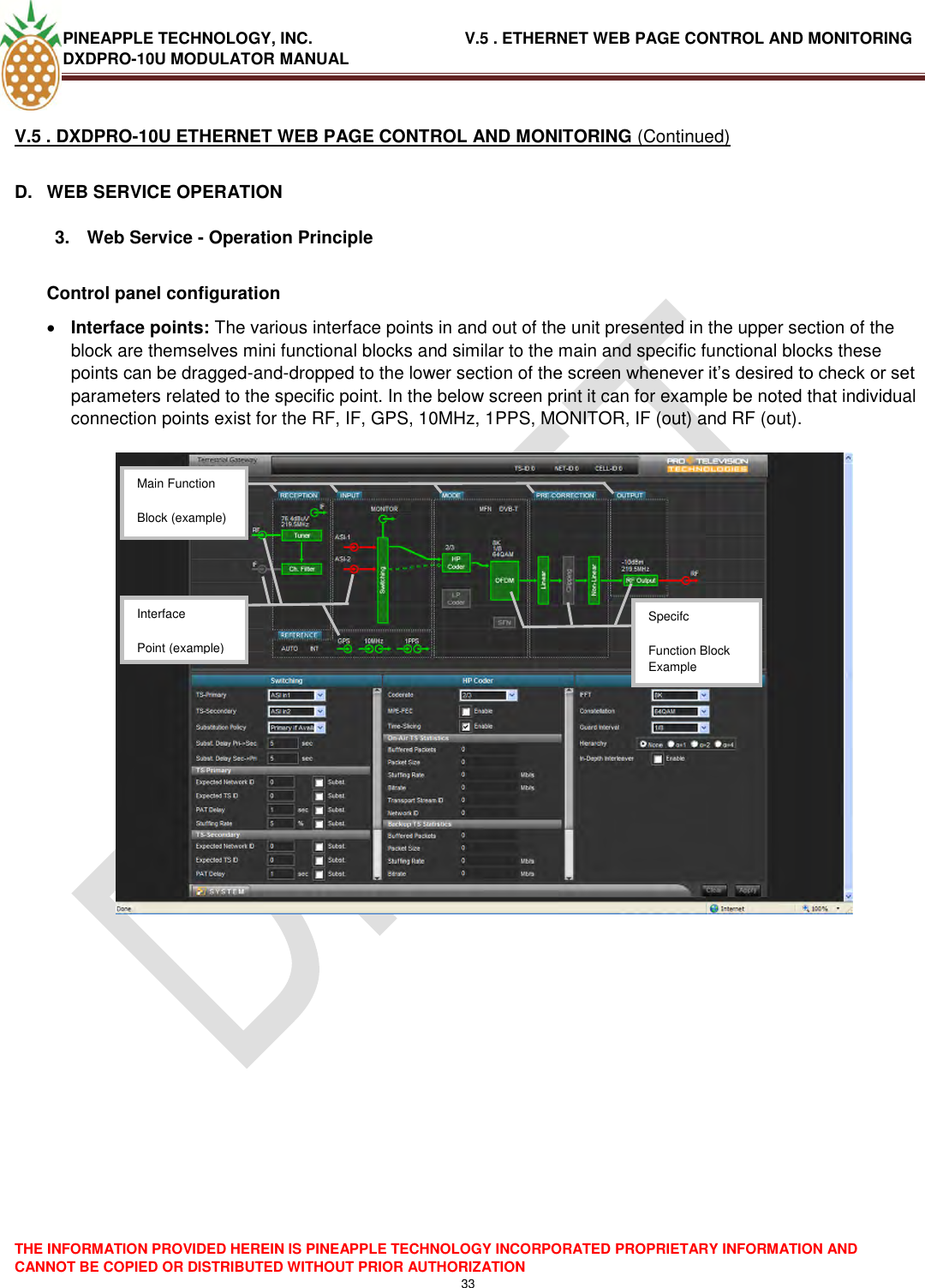
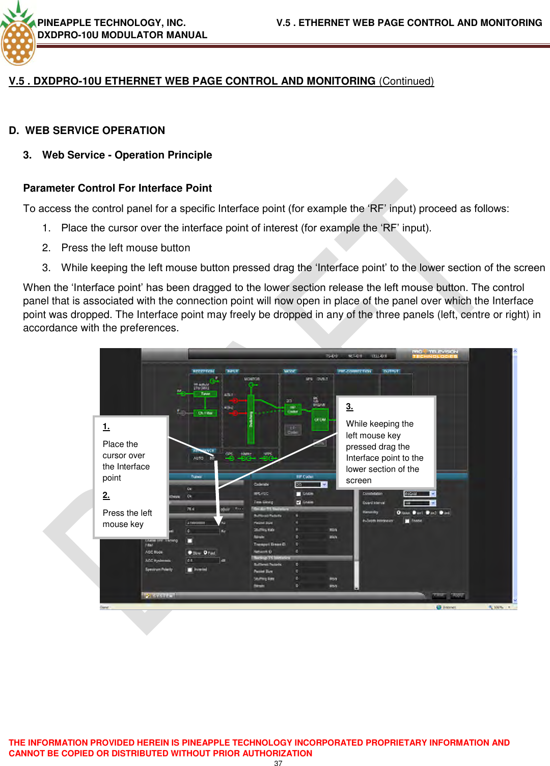
![PINEAPPLE TECHNOLOGY, INC. V.5 . ETHERNET WEB PAGE CONTROL AND MONITORING DXDPRO-10U MODULATOR MANUAL THE INFORMATION PROVIDED HEREIN IS PINEAPPLE TECHNOLOGY INCORPORATED PROPRIETARY INFORMATION AND CANNOT BE COPIED OR DISTRIBUTED WITHOUT PRIOR AUTHORIZATION 39 V.5 . DXDPRO-10U ETHERNET WEB PAGE CONTROL AND MONITORING (Continued) D. WEB SERVICE OPERATION 3. Web Service - Operation Principle Access To System Parameters 3: When the parameter of interest in the system menu has been verified or set as required click the [x] to close the system menu and revert to the normal three-panel display 2: From the system menu select the required sub menu (for example ‘Preset‘) by left-clicking the menu point 1: Left-click the [SYSTEM] button to open the system configuration menu.](https://usermanual.wiki/Pineapple-Technology/DTXPRO2300U/User-Guide-1414764-Page-41.png)
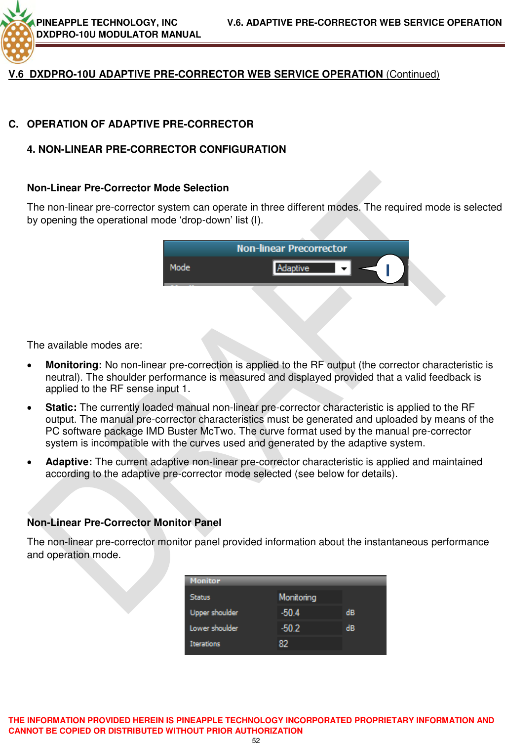
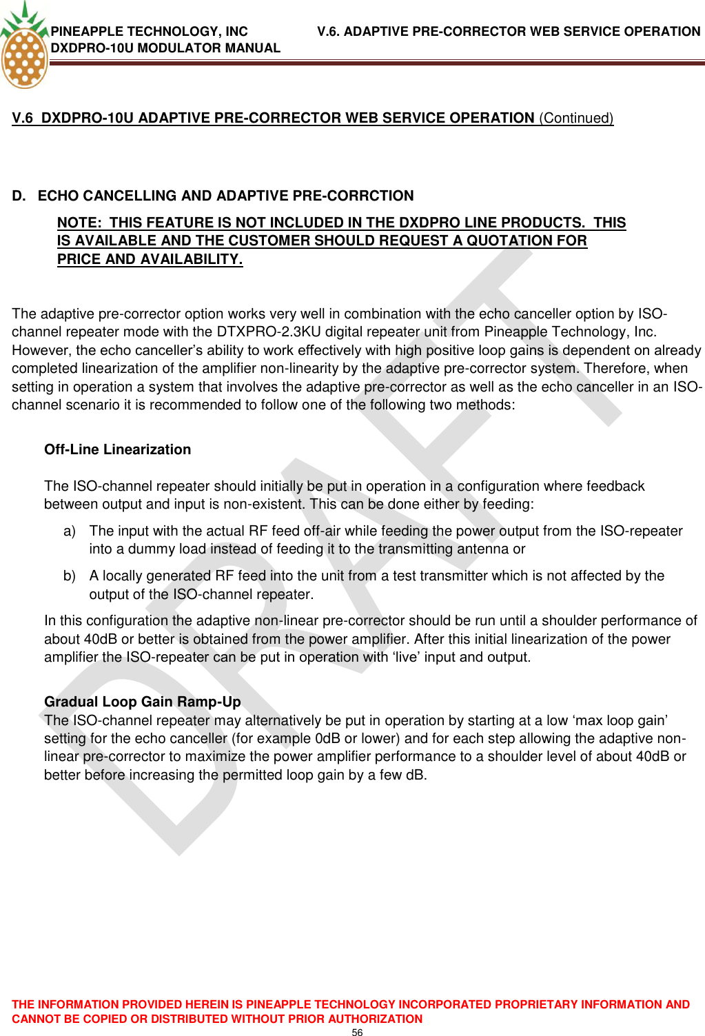
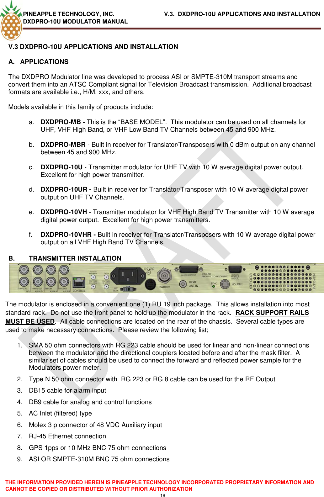
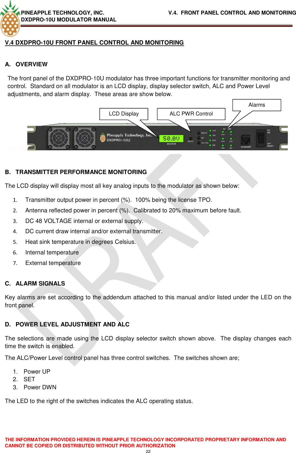
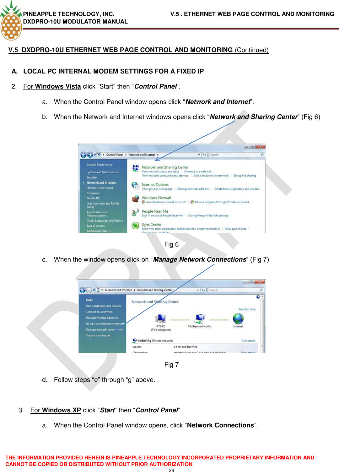
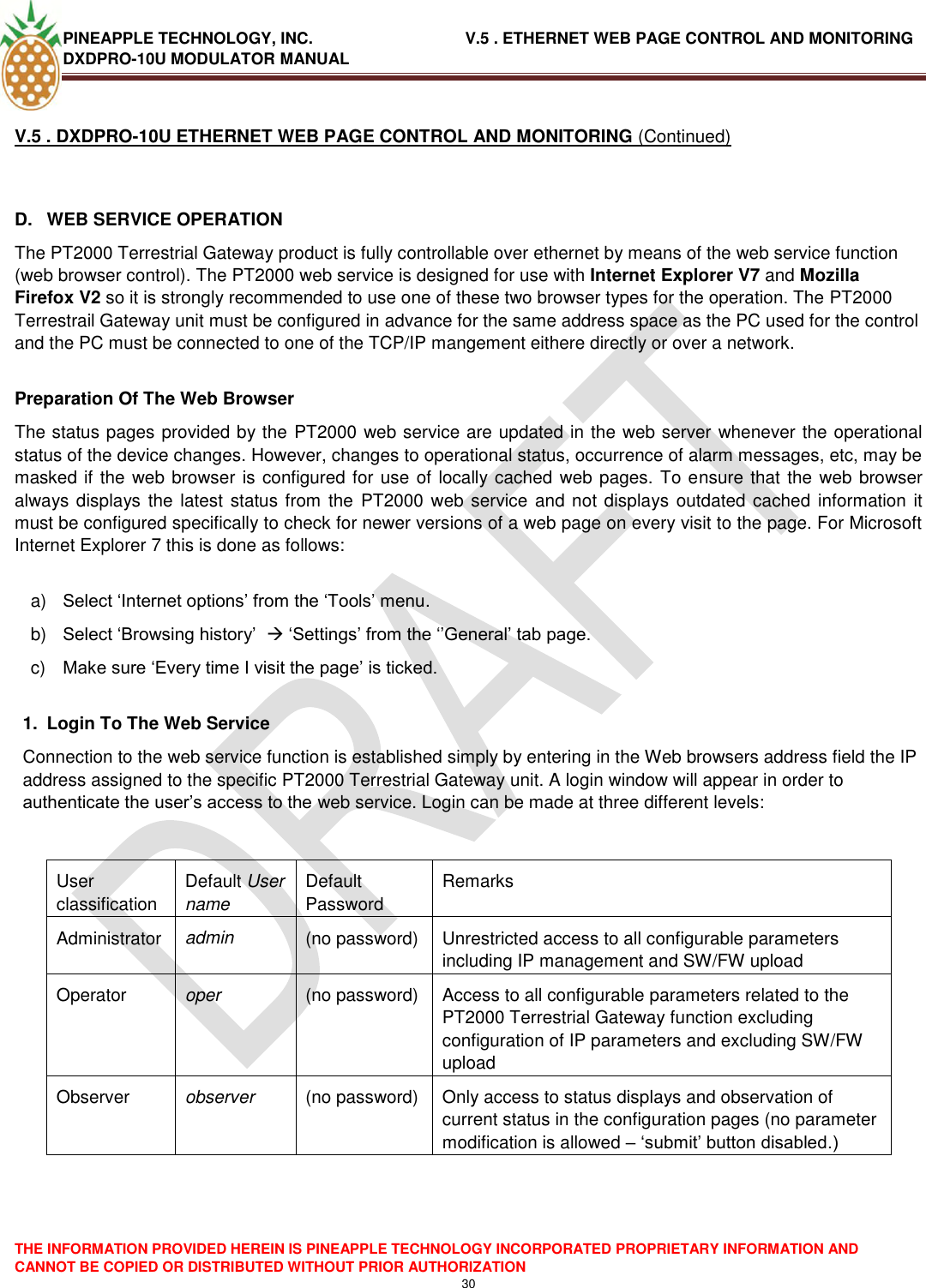
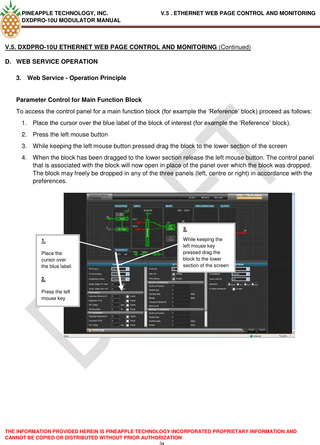
![PINEAPPLE TECHNOLOGY, INC. V.5 . ETHERNET WEB PAGE CONTROL AND MONITORING DXDPRO-10U MODULATOR MANUAL THE INFORMATION PROVIDED HEREIN IS PINEAPPLE TECHNOLOGY INCORPORATED PROPRIETARY INFORMATION AND CANNOT BE COPIED OR DISTRIBUTED WITHOUT PRIOR AUTHORIZATION 40 V.5 . DXDPRO-10U ETHERNET WEB PAGE CONTROL AND MONITORING (Continued) D. WEB SERVICE OPERATION 3. Web Service - Operation Principle Setting Of A Parameter Value To change the setting of a specific user parameter, proceed as follows: 1. If not already available for modification move the functional block in which the parameter resides to the control panel in the lower section of the screen as described above. 2. Place the cursor over the location in the control panel where the parameter of interest resides and click the left mouse button to set the point in focus. Depending on the type of input set the new value as required. The input can be ‗alpha-numeric for input by keyboard‘ or based on a drop-down list holding the valid choices or based on a tick-box or radio-button system. Notice that some fields are status displays only (read only) and that it consequently isn‘t possible to access these fields for parameter change. 3. When the new value has been specified the border of the field in question will be presented in a light blue color to indicate that a new value has been specified but not yet implemented/confirmed. 4. To implement/confirm the new value move the cursor to the [Apply] button and click the left mouse button to confirm the entry. 5. When the new value has implemented/confirmed the light blue border around the parameter input field will return to the normal black color. Parameter control of the ’drop-down’ list type. The control will provide the list of valid choices for selection when left-clicked with the mouse. Parameter control of the ’radio-button’ type. Select a new value by left-clicking the value in the control. Parameter control of the ’tick-box’ type. Left click the control to toggle the value between the two possible states Parameter control for numeric input. Specify the value using the keyboard after selecting the control by left-clicking the mouse. Note the grey border which indicates that this box accepts user input. Parameter box of the read-only type (status only). This box differs from the ‘input‘ type of box by the absence of the grey border that characterizes the boxes for alpha-numeric input. Apply button for implementing/confirming the new parameter value Clear button for cancelling a modified but not yet implemented/confirmed parameter value](https://usermanual.wiki/Pineapple-Technology/DTXPRO2300U/User-Guide-1414764-Page-42.png)
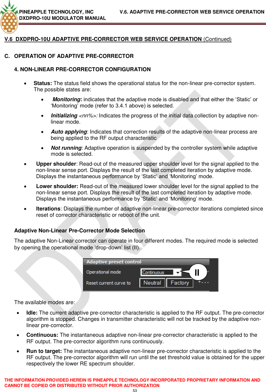
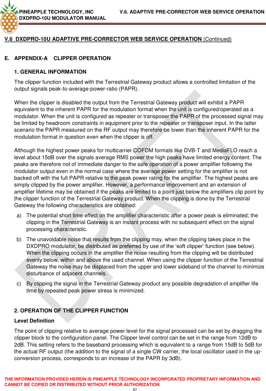
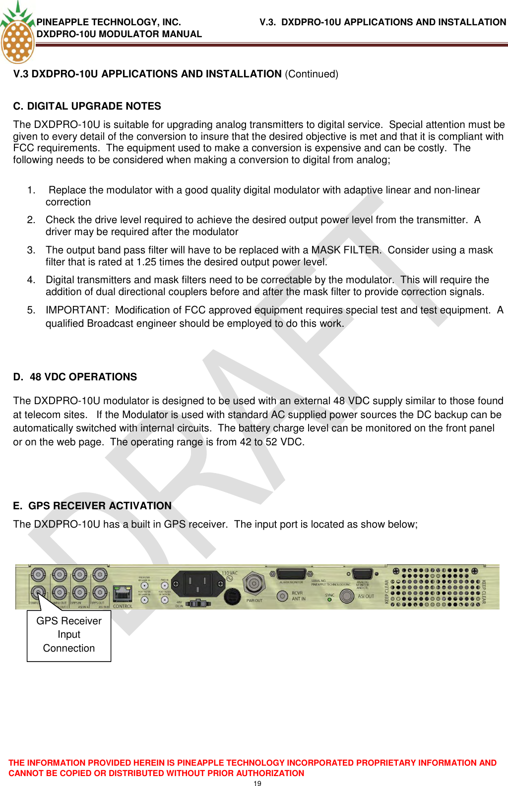
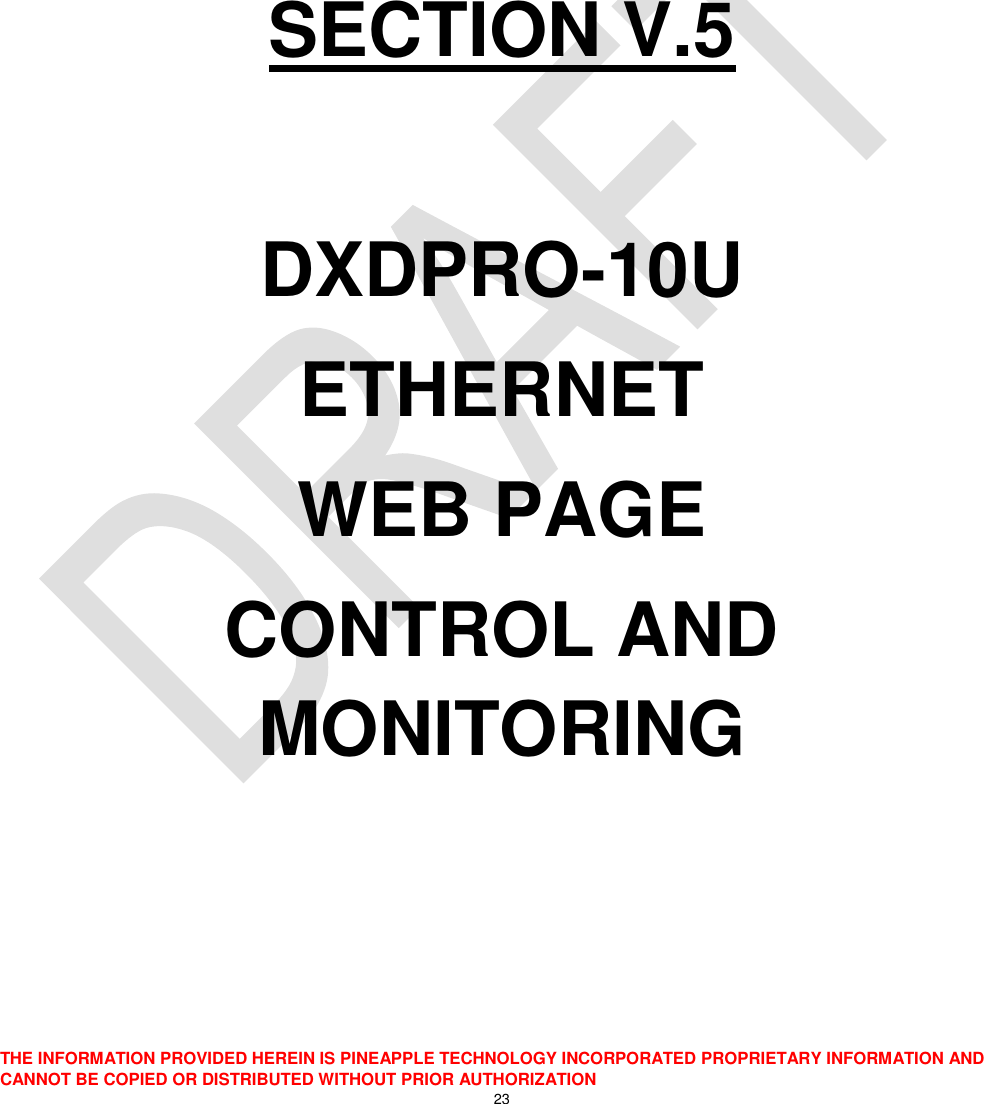
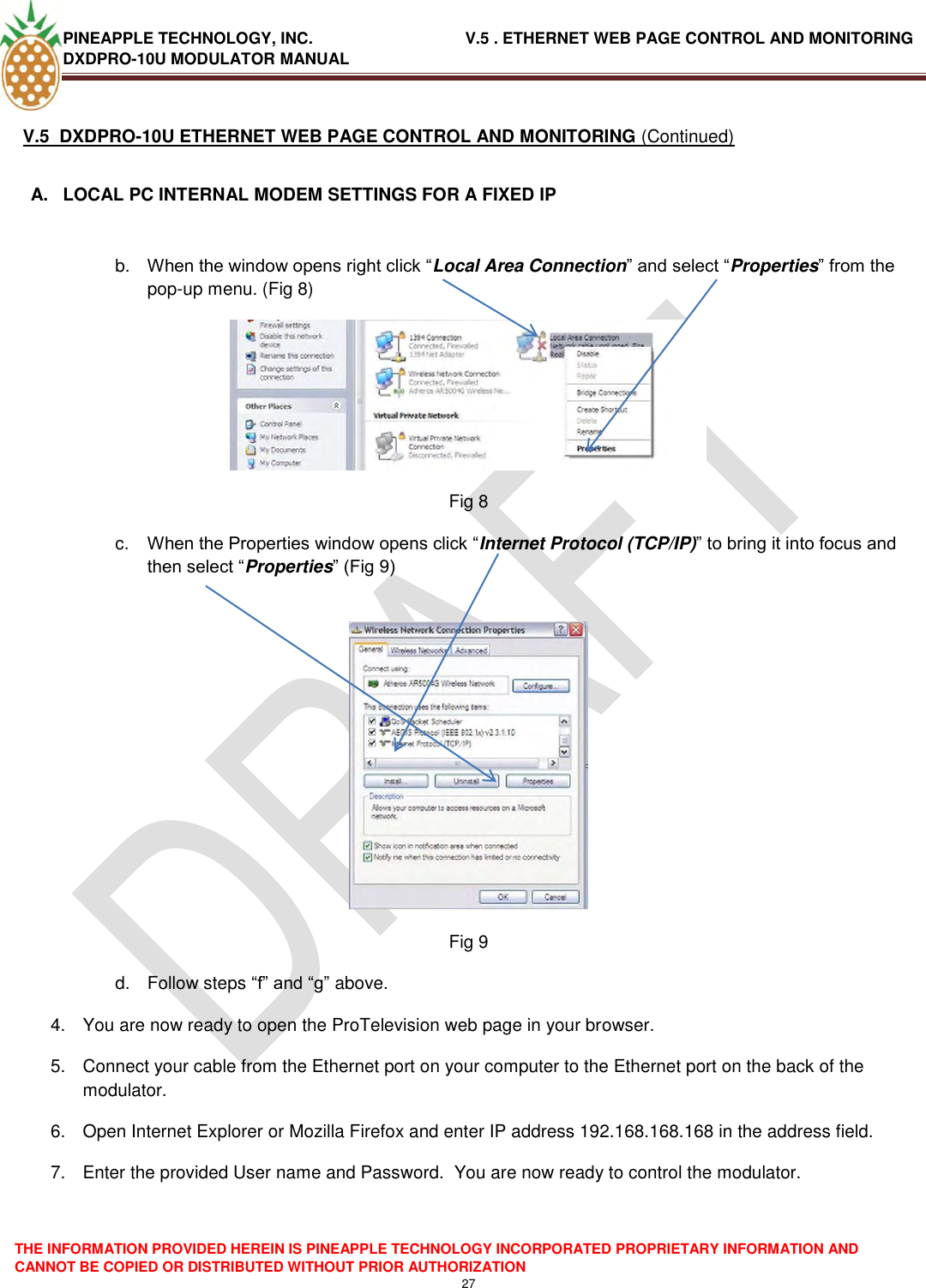
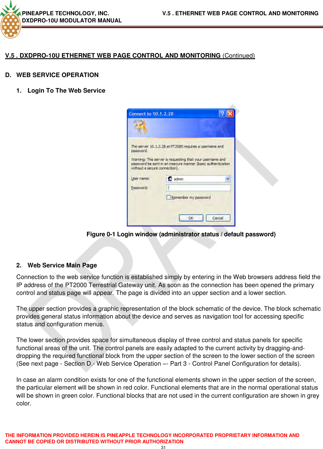
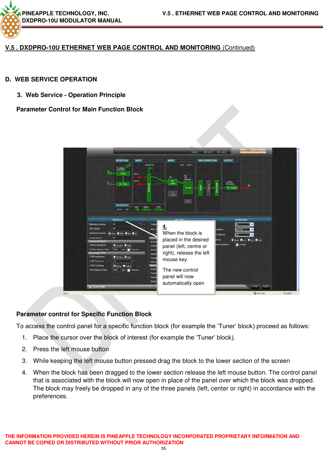
![PINEAPPLE TECHNOLOGY, INC. V.5 . ETHERNET WEB PAGE CONTROL AND MONITORING DXDPRO-10U MODULATOR MANUAL THE INFORMATION PROVIDED HEREIN IS PINEAPPLE TECHNOLOGY INCORPORATED PROPRIETARY INFORMATION AND CANNOT BE COPIED OR DISTRIBUTED WITHOUT PRIOR AUTHORIZATION 41 V.5 . DXDPRO-10U ETHERNET WEB PAGE CONTROL AND MONITORING (Continued) D. WEB SERVICE OPERATION 3. Web Service - Operation Principle SW/FW update SW/FW update of the PT2000 Terrestrial Gateway product is carried out over the ethernet interface. The update is based on a so called ‗tarball‘ file that contains the SW/FW images that define the specific product version (for example a DVB-T/H modulator, an ATSC modulator or a MediaFLO modulator). The typical size of the ‗tarball‘ is about 16Mb. The update procedure is as follows: 1. Download the ‗tarball‘ file from the FTP site to a directory on your local network or to the PC that you are using explicitly for managing the PT2000 Terrestrial Gateway unit or insert the CDROM that contains the tarball into a CDROM drive on this PC. 2. Connect to the Web service interface of the PT2000 Terrestrial Gateway product as described in Section D, Web Service Operation--1. Login to the Web Server, page 31. 3. In the lower left corner of the Web service graphical user interface you will find the [System] button. Click this button to open the system menu. 4. In the system menu select the function [SW Upgrade]. See Section D, Web Service Operation—Subsection 3- Web Service - Operation Principle - Access to System Parameters, on page 39, for further details about access to the system menu. 5. In the Maintenance section of the System menu select Software Upgrade 6. Select [Browse] and navigate to the location of the downloaded ‗tarball‘ file 7. Select the file ‗tarball.tgz’ and click [Upload] 8. The loading of the new SW/FW should now start automatically. The progress can be monitored from the Web service interface. A number of steps including uploading, unpacking and verifying and deleting files will pass automatically (the processing time is several minutes). 9. When the loading of new SW/FW is completed the unit will automatically reboot. After the reboot the new SW/FW version is active. 10. The active SW/FW version can be verified after the reboot via the [About] function in the [System] menu](https://usermanual.wiki/Pineapple-Technology/DTXPRO2300U/User-Guide-1414764-Page-43.png)