Pineapple Technology LTX100U 100 WATT TV ANALOG BROADCAST TRANSMITTER User Manual
Pineapple Technology, Inc. 100 WATT TV ANALOG BROADCAST TRANSMITTER
User Manual
LTX100U/VH/VL TRANSMITTERS
INSTRUCTION MANUA
L
PINEAPPLE TECHNOLOGY, INC

PINEAPPLE TECHNOLOGY, INC.
LTX100U/VH/VL Operating and Service Manual TABLE OF CONTENTS
Section l --- SAFETY NOTICES ………………………………………………………………………
…
2
** READ THIS SECTION BEFORE INSTALLATON *
*
Secton ll --- TRANSMITTER SPECIFICATIONS …………………...………………………………
…
3
Section lll --- TRANSMITTER INSTALLATION ……………………………………………………
…
5
Section lV --- TRANSMITTER TURN-ON ……………………………………………………………
…
6
Section V --- THEORY OF OPERATION
A
. Introduction ……………………………………………………………………………
…
8
B. MA1000 Modulator………………………………………………………………………
…
8
C. LTX Mainframe Assembly ……………………………………………………………… 8
D. BPU150/BPLV750/BPHV750 Broadband Filter………………………………………
…
9
SECTION Vl --- SCHEMATIC AND PARTS LISTS
A
. LTX100U/VH/VL…………………………………………………………....................... 10
B. LTX Mainframe Assembly………………………………………………………………
…
14
C. BPU150/BPLV750/BPHV750 Broadband Filter………………………………………
…
21
SECTION Vll --- RECOMMENDED ROUTINE MAINTENANCE …………………………………
…
23
SECTION Vlll --- ADJUSTMENTS AND TUNING …………………………………………………… 24
SECTION lX --- PROBLEM SOLVING / TROUBLESHOOTING …………………………………
…
25
SECTION X --- WARRANT
Y
…………………………………………………………………………… 27

Section I
Safety
Notices

PINEAPPLE TECHNOLOGY, INC.
LTX100U/VH/VL Operating and Service Manual l --- SAFETY NOTICES
l ---SAFETY NOTICES
** READ THIS SECTION BEFORE INSTALLATION **
SEVERE ELECTRICAL SHOCK OR BURNS MAY OCCU
R
IF THIS EQUIPMENT IS USED IMPROPERLY.
NEVER WORK ON THIS EQUIPMENT ALONE. ALWAYS HAVE ANOTHER PERSON PRESENT
WHILE WORKING ON ELECTRICAL CIRCUITS OR MOVING EQUIPMENT. COMMUNICATIONS
TO EMERGENCY SERVICES SHOULD BE AVAILABLE AT ALL TIMES.
BEFORE CONNECTING THIS EQUIPMENT TO ANY AC ELECTRICAL SOURCE READ THE
SECTION ON INSTALLATION. ALL ELECTRICAL WIRING FOR THIS EQUIPMENT MUST BE
PERFORMED BY QUALIFIED ELECTRICIANS. ALL WIRING MUST BE COMPLIANT WITH
LOCAL ELECTRICAL CODES.
POWER AMPLIFIERS AND SUPPLIES ARE HEAVY. TO INSTALL THIS EQUIPMENT IN RACKS
USE TWO (2) PERSONS TO AVOID POSSIBLE INJURIES.
NEVER OPEN THE CABINET ENCLOSURE OR UNPLUG CABLES OR WIRES WHILE THIS
EQUIPMENT IS OPERATING.
ALL SERVICE WORK MUST BE PERFORMED BY QUALIFIED TECHNICIANS ONLY
.
IF ONE IS NOT AVAILABLE LOCALLY, CONTACT PINEAPPLE TECHNOLOGY, INC. FOR
A LIST IN YOUR AREA.
Page 2

Section II
Transmitter
Specifications

THESE SPECIFICATIONS ARE SUBJECT TO CHANGE WITHOUT NOTICE.
PINEAPPLE TECHNOLOGY, INC.
LTX100U/VL/VH Operating and Service Manual II – TRANSMITTER SPECIFICATIONS
II – LTX100U/VL/VH SPECIFICATIONS
OPERATING
Power Output ………………………… 100 Watts P-Sync
5 Watts Aural
RF Output Impedance………………… 50 ohms
Frequency Range
LTX100U……………………...470 – 806 MHz
LTX100VL…………………….CH 2 – CH 6
LTX100VH……………….……CH7 – CH13
Frequency Stability…………………… 1 PPM or better
Harmonic and Spurious………………... -50 db
Power Consumption…………………… 500W maximum
AC Line Voltage……………………… 85 – 120 VAC Single Phase
VIDEO PERFORMANCE
Visual Frequency Response…………… +/- 1 db across the TV channel -1.25 MHz to 4.75 Mhz
relative to visual carrier.
Differential Gain……………………………..< 7%
Low Frequency Linearity………………….. < 15%
Group Delay……………………………….. Meets FCC Part 73 Rule
Video Input Impedance……………………. 75 ohms
Video Input Level………………………….. 1 volt p-p
Variation of Output Power…………………. < 5%
Regulation of Output Power……………….. < 5% typical
Video Signal to Noise Ratio……………….. < 45 db un-weighted
Page 3

THESE SPECIFICATIONS ARE SUBJECT TO CHANGE WITHOUT NOTICE.
PINEAPPLE TECHNOLOGY, INC.
LTX100U/VL/VH Operating and Service Manual II – TRANSMITTER SPECIFICATIONS
AUDIO PERFORMANCE
Audio Response…………….…………. Meets FCC Pre-emphasis curve
Distortion…………………………………….< 1% THD
FM Noise…………………………............... < 50 dB or better
AM Noise……………………………………< 40 dB or better
AM Synchronous Noise……………………. < 40 dB typical
GENERAL
Operating Temperature…………………….. -10 to +35 Degrees Celsius Ambient
+14 to +95 Degrees Fahrenheit Ambient
Altitude…………………………………….. 5,000 ft without additional cooling
Cooling Requirement………………………. Built in, except where noted
Connectors…………………………………..BNC Connector Input, N Connector Output
Weight………………………………………100 lbs
Dimensions Overall…………………………21” x 25” x 24” (W x H x D) Standard
Page 4

Section III
Transmitter
Installation

PINEAPPLE TECHNOLOGY, INC.
LTX100U/LV/LH Operating and Service Manual lll -- TRANSMITTER INSTALLATION
lll -- TRANSMITTER INSTALLATION
To ensure long and reliable trouble-free service from the LTX100U/LV/LH transmitters the following steps
for installation are recommended:
1. MECHANICAL INSTALLATION: The LTX100U/LV/LH transmitters were designed to be installed in
a building protected from the weather. The building should have a hard-surface floor such as
concrete with a moisture barrier. This barrier could be pressure-treated wood sub flooring which
could be anchored to the concrete and to the transmitter to make the installation earthquake
resistant. For ease of operation and maintenance, the transmitter cabinet will need to be securely
mounted to a raised structure at some appropriate distance above the floor.
Provisions for air inlet and exhaust from the room must allow air flow with minimal obstruction.
In the event that the room temperature exceeds 35º Celsius (95º F), cooling air must be provided
so that the room temperature will not exceed 35 degrees Celsius under worse case conditions.
Notice: This equipment is HEAV
Y
and must be handled by professional movers with prope
r
equipment. Any damage caused by the installers is not covered under warranty. Check to ensur
e
that installing crews have proper insurance coverage.
2. GROUNDING: Transmitter grounding is
V
ERY IMPORTANT and must be done correctly fo
r
safety and operational reasons. A typical installation may be done as follows
:
Use a heavy gauge wire such as 16 AWG stranded copper. The bonding between the transmitter
and the ground rods must be good quality and protected from corrosion. The ground wires should
run over the floor and be connected to the ground rods located outside the building. The wire
should not go through the concrete floor but over and around it.
3. AC WIRING: The LTX100U/LV/HV transmitters come with a three wire 110 VAC standard plug for
connection to a 110 VAC electrical outlet. It is recommended that the electrical outlet be protected
with its own separate breaker and used only for the transmitter.
NOTICE: All wiring of this type, except for the actual connection to the AC plug, must be done
by a QUALIFIED ELECTRICIAN and must conform to LOCAL and NATIONAL wiring CODES.
Consult with your electrician to ensure that the proper breaker size is selected for the main circuit.
4. ANTENNA CONNECTION: The transmitters are equipped with an N connector for output power
to the transmit antenna and an F connector for connection from the receive antenna.
Page 5

Section IV
Transmitter
Turn-On

PINEAPPLE TECHNOLOGY, INC.
LTX100U/VL/VH Operating and Service Manual lV -- TRANSMITTER TURN-ON PROCEDUR
E
lV --- TRANSMITTER TURN-ON PROCEDURE (Page 1 of 2
)
See the previous section on installation before proceeding with this section. Improper installation of th
e
transmitter can cause serious damage to the equipment or operating personnel and may voi
d
manufacturers warranty. Initial turn on and check out is very important for the broadcast engineer t
o
learn how to setup and operate the transmitter. Following these steps will ensure long and reliable operation
:
1. Check the transmitter output load or antenna for proper installation and connection to the transmitter
.
2. Inspect the transmitter front and back to check for broken items or lose fitting items. These mus
t
be replaced or properly secured before turning the transmitter on. Pay special attention to all R
F
connectors including transmit coaxial cable and antenna.
3. Check the AC breaker and on/off switches to ensure that all are in the OFF position.
4. Verify the switch on the power strip at the back of the cabinet and the power switch on the front of the
LTX Mainframe are in the OFF position. Plug in the AC power cord to a nearby 110 AC electrica
l
connector with associated, appropriately sized, circuit breaker
.
5. On the MA1000 Modulator, turn the Output Power potentiometer fully counter clockwise to minimum.
6. Turn-on the AC Power switch located on the power strip at the rear of the LTX100U/VL/VH cabinet.
7. Locate and turn on the front panel breaker found on the LTX Mainframe and set the XMT
R
switch
to the ON position.
MAKE THE FOLLOWING OBSERVATION
S
METER READINGS TYPICAL
DC SUPPLY VOLTAGE 32 VDC
PA1 DRIVER CURREN
T
1.7 AMPS ± 20%
PA2 FINAL CURREN
T
2.7 AMPS ± 20%
PA3 FINAL CURREN
T
1.3 AMPS ± 20%
RF OUTPUT POWER 10 TO 50%
RFL'D POWER < 10%
NOTE STATUS LIGHTS
FAN GREEN
TEMP GREEN
+DC GREEN
THE FAN SHOULD BE MAKING SOME NOISE
Page 6

PINEAPPLE TECHNOLOGY, INC.
LTX100U/VL/VH Operating and Service Manual lV -- TRANSMITTER TURN-ON PROCEDURE
lV --- TRANSMITTER TURN-ON PROCEDURE (Page 2 of 2)
Note: Allow the LTX100U/VL/VH to warm up for at least one (1) hour before making the final adjustment.
If transmitter is not warmed up, the output power will require re-adjustment to proper level when it is warm.
8. Select the FWD Power setting on the rotary switch associated with the front panel meter on the LTX
Mainframe assembly. Slowly adjust the Output Level setting on the MA1000 Modulator while observing the
output power level on the front panel meter until the meter reading indicates 50% output power. At this
point, check the reflected power indication on the LTX meter. The reading should be less than 5% if the
output connection, cable and antenna have been previously verified to have a VSWR of less than 1.2:1.
9. If the output level is stable at the 50% point for 5 or 10 minutes, it is OK to increase the drive to achieve
a reading of 100%. This is the output level set at the factory for your transmitter and is p-sync reading.
RECORD AND RETAIN THE FOLLOWING OBSERVATIONS FOR FUTURE REVIEW IF NECESSARY
METER READINGS TYPICAL
DC SUPPLY VOLTAGE 32 VDC
PA1 DRIVER CURREN
T
1.8 AMPS ± 20%
PA2 FINAL CURREN
T
3.4 AMPS ± 20%
PA3 FINAL CURREN
T
2.8 AMPS ± 20%
RF OUTPUT POWER 90 TO 100%
RFL'D POWER < 10%
NOTE STATUS LIGHTS
FAN GREEN
TEMP GREEN
+DC GREEN
10. Check the transmitter on-the-air signal with a monitor to ensure all is well and you're done.
Page 7

Section V
Theory
of
Operation

PINEAPPLE TECHNOLOGY, INC.
LTX100U/VL/VH Operating and Service Manual V -- THEORY OF OPERATION
V
--- THEORY OF OPERATION (Page 1 of 2)
A
. INTRODUCTION
The LTX100U/VL/VH series transmitters were designed to meet or exceed all FCC applicable specifications for
TV broadcast equipment. Special attention was given to the selection of sub-assemblies and components
to achieve maximum reliability and minimum down time. The construction of the LTX100U/VL/VH is
BASIC and MODULAR with most components are field replaceable. Special emphasis was placed on
"KEEPING IT SIMPLE" and returning to more traditional transmitter layouts and instrumentation.
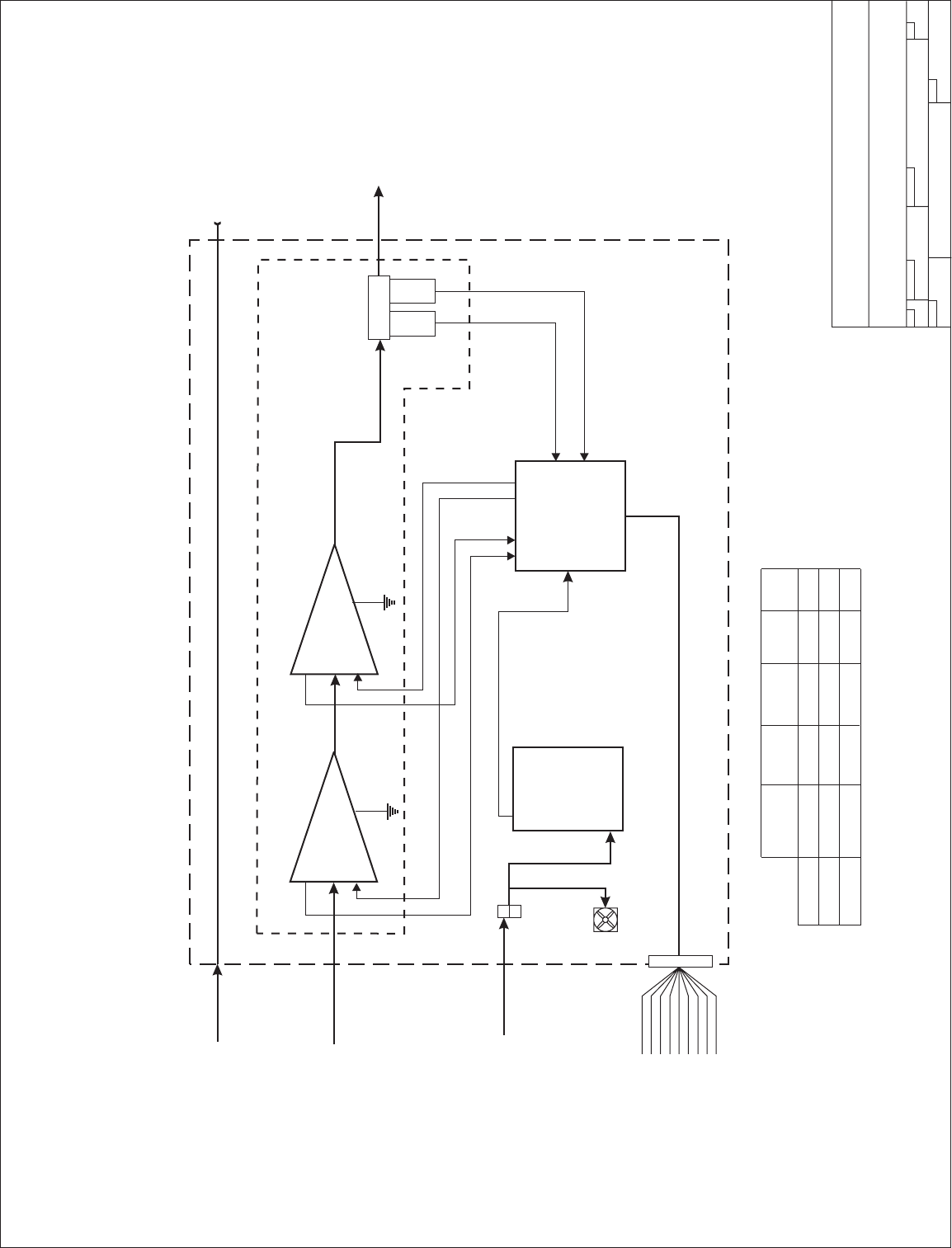
Refer to the LTX100U/VL/VH block diagram for an overview of the transmitter architecture. This will
give the technician basic information needed to understand the operation of the transmitter and the function
of each subassembly.
SEE SECTION Vl.A FOR PARTS LIST AND BLOCK DIAGRAM.
B. MA1000 Modulator/Exciter
The modulator/exciter is set up at the factory for the operating frequency (Channel) specified by the
customer as shown on the appropriate FCC document including any appropriate offset.
Refer to the Cadco user manual at the end of this manual for information on the modulator.
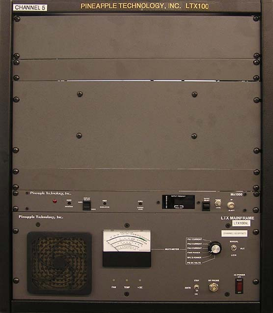
C. LTX100( ) Mainframe Power Amplifier
Cabinet - The cabinet is constructed of heavy gauge steel and is very durable. This enclosure is
painted black and is resistive to harsh environment. Standard 19 inch rack mounting.
The LTX100( ) Mainframe is the power amplifier assembly that accepts the video and audio signal
from the modulator/exciter and raises it up to the required output power which will be sent to th
e
antenna.
LTX100( ) Mainframe Assembly's internal sub-assemblies include the following:
1. DC Power Suppl
y
2. RF Deck
3. Status Monitoring (1A0035)
4. Output Power Detector Board (1A0027)
5. Reflected Power Detector (1A0029) and Shutdown Switch
6. Metering and Monitoring Assembly (1A0300
)
Page 8

PINEAPPLE TECHNOLOGY, INC.
LTX100U/VL/VH Operating and Service Manual V -- THEORY OF OPERATION
V
. THEORY OF OPERATION (CONTINUED) (Page 2 of 2)
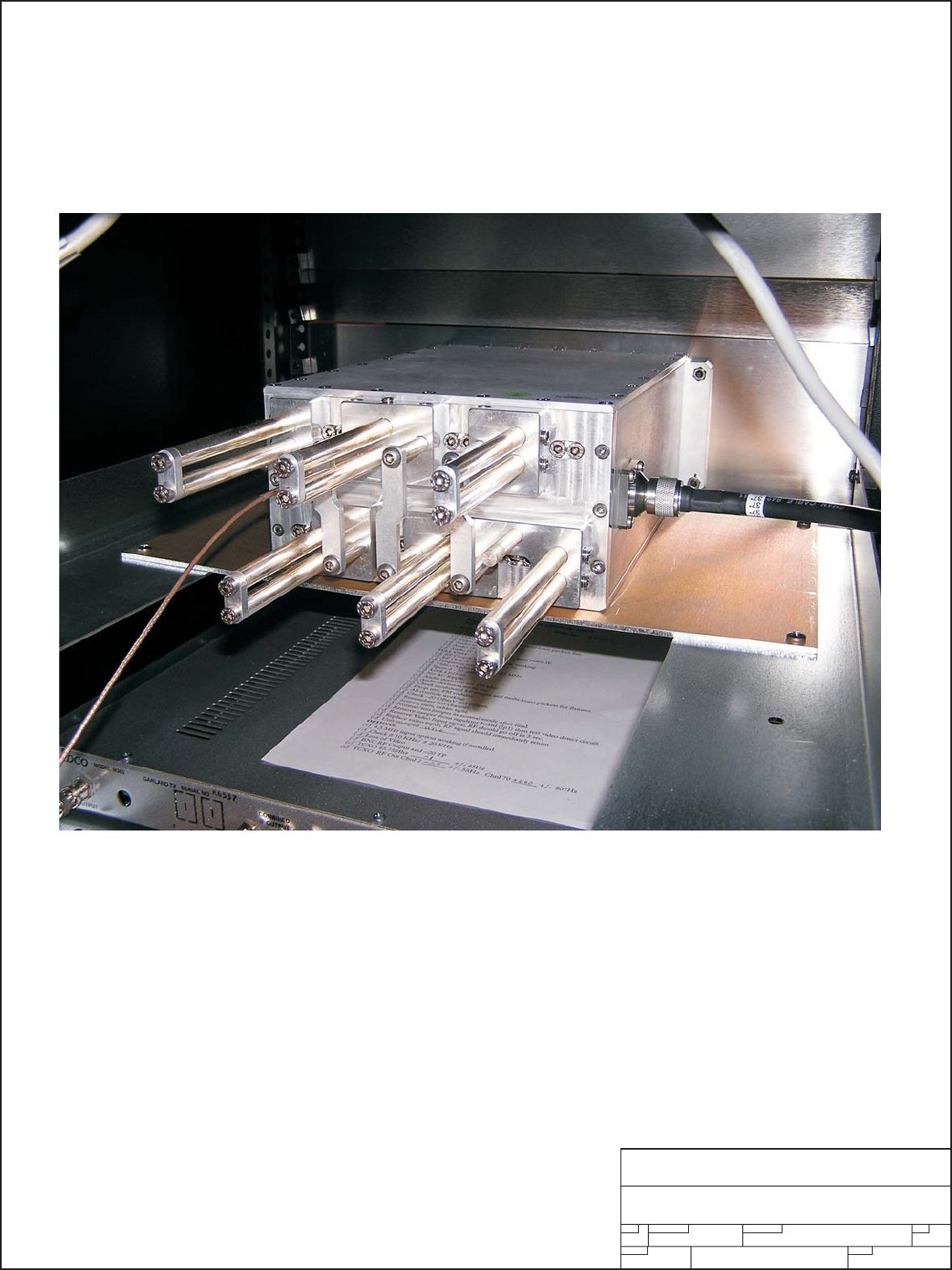
D. BAND PASS FILTERS
BPU150N - Used in the LTX100U UHF Transmitter
BPVH300N - Used in the LTX100VH High VHF Band (Ch 7 - 13) Transmitter
BPVL200N - Used in the LTC100VL High VHF Band (Ch 2 - 6) Transmitter
These Band Pass filters were designed to meet FCC Certification requirements with minimum loss of
RF Power. Thy come tuned and tested to the operating frequency of the transmitter
and should not be adjusted without proper equipment. Replacement filters are available as
from Pineapple Technology, Inc. upon request.
Page 9

Section VI
Schematic
and
Parts List

PINEAPPLE TECHNOLOGY, INC.
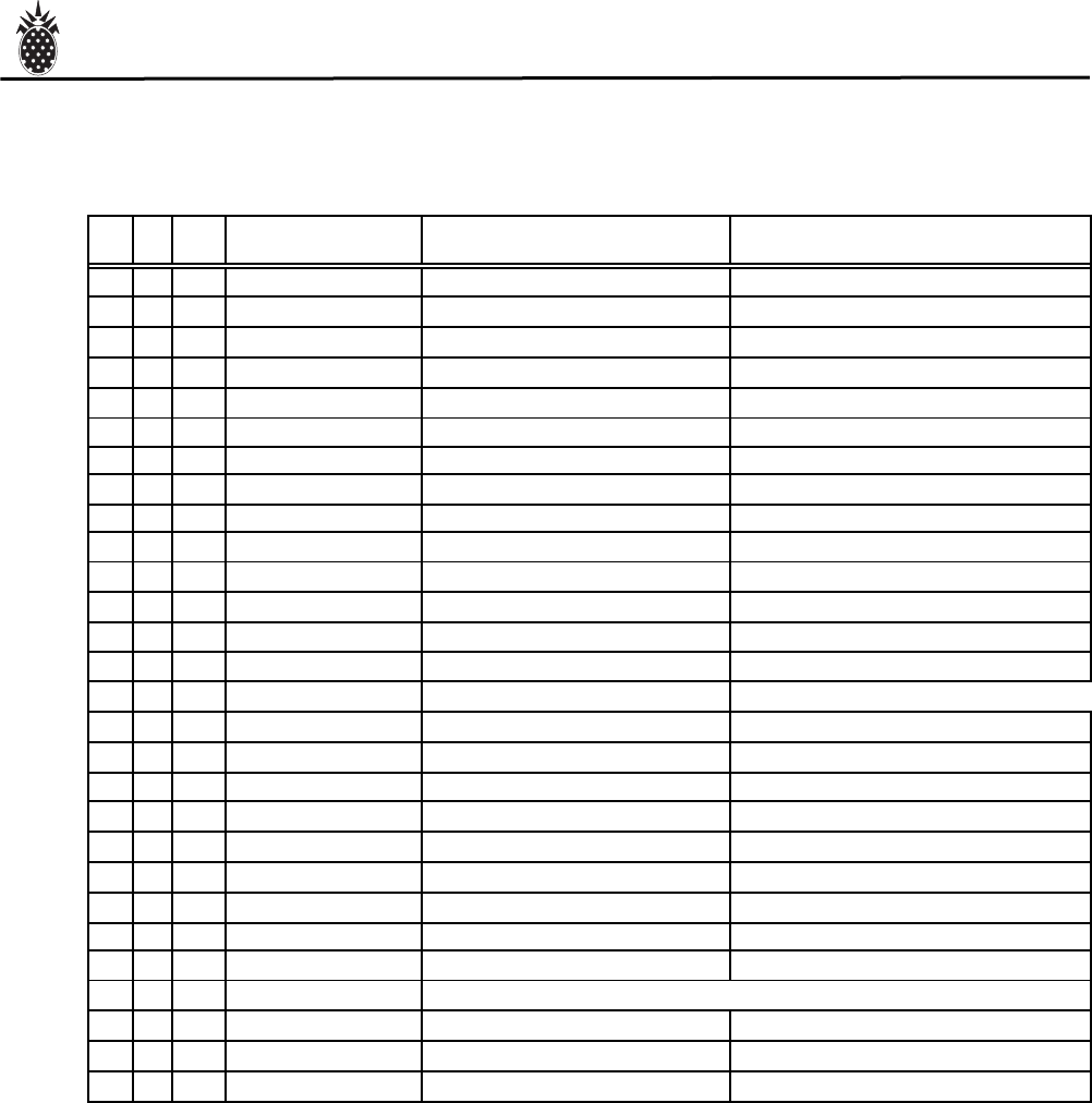
LTX100U/VL/VH Operating and Service Manual Vl -- SCHEMATICS AND PARTS LIST
A. LTX100U ASSY TREE
Item Qty Type P/N Title Detail
Top CAT LTX100U LTX SERIES UHF TRANSMITTER 100 WATTS
1 1 PL LTXMAINFRAME UH
F
LTX SERIES XMTR 100 W UHF BASIC UNIT
2 1 CAT MA1000 M369 CADCO MODULATOR MODIFIED TO PTI SPECS
3 1 PS BPU150N BP FILTER 150 W UHF 470-862 MHz
4 1 PS MFR13RU EQUIPMENT RACK 13 RU BLK 19 IN DEEP
LTX100U Assy Tree
Page 10

PINEAPPLE TECHNOLOGY, INC.
LTX100U/VL/VH Operating and Service Manual Vl -- SCHEMATICS AND PARTS LIST
A. LTX100VL ASSY TREE
Item Qty Type P/N Title Detail
Top CAT LTX100VL LTX SERIES XMTR VHF LOW BA
N
100 WATTS
1 1 CAT LTXMAINFRAME VH
F
LTX SERIES XMTR 100 W VHF L
B
BASIC UNIT
3 1 CAT MA1000 M369 CADCO MODULATOR MODIFIED TO PTI SPECS
4 1 PS BPVL200N BP FILTER LTX XMTR VHF LB TYPE N CONNECTORS 200 W
6 1 PS MFR13RU EQUIPMENT RACK 13 RU BLK 19 IN DEEP
LTX100VL Assy Tree
Page 11

PINEAPPLE TECHNOLOGY, INC.
LTX100U/VL/VH Operating and Service Manual Vl -- SCHEMATICS AND PARTS LIST
A. LTX100VH ASSY TREE
Item Qty Type P/N Title Detail
Top CAT LTX100VH LTX SERIES VHF HB 100 WATT
X
100 WATT
1 1 PL LTXMAINFRAME VH
F
LTX SERIES XMTR 100 W VHF H
B
BASIC UNIT
3 1 PS BPVH300N BP FILTER 300W VHF HB CL3NV TYPE N CONNECTORS
4 1 PS MFR13RU EQUIPMENT RACK 13 RU BLK 19 IN DEEP
5 1 CAT MA1000 M369 CADCO MODULATOR MODIFIED TO PTI SPECS
LTX100VH Assy Tree
Page 12
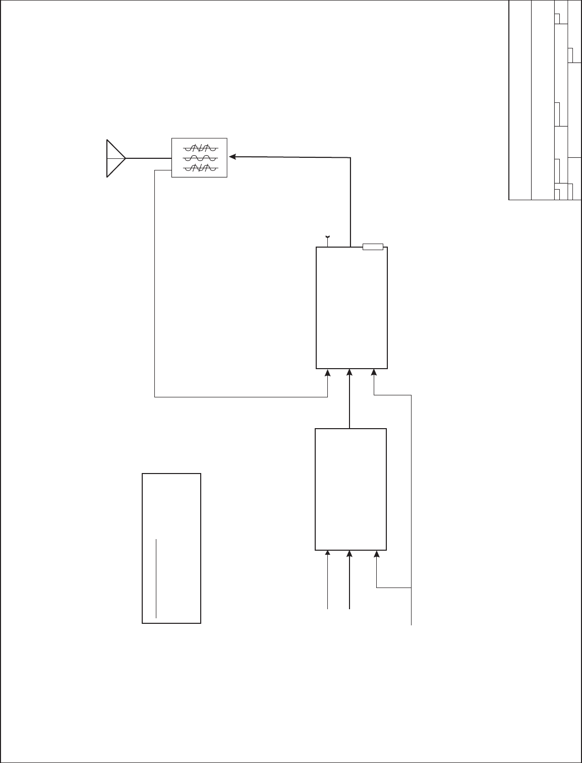
Band Pass
Filter
AC Inlet
AC Inlet
Video In
Audio In RF Input
RF Output Mon RF Probe
Remote
Interface
Video
Audio MA1000
Modulator
Band Pass Filters
BPU150N used for LTX100U
BPVH300N used for LTX100VH
BPVL200N used for LTX100VL
LTX100( )
Mainframe
Assembly
LTX100U/VH/VL
UHF Transmitter
AB
1
1:1
DB9
SIZE FSCM NO.
SCALE SHEET
DWG NO. REV
Pineapple Technology, Inc.
Rocklin, CA
110 VAC
Page 13

PINEAPPLE TECHNOLOGY, INC.
LTX100U/VL/VH Operating and Service Manual Vl -- SCHEMATICS AND PARTS LIST
A. LTX Mainframe UHF Assy Tree
Item Qty Type P/N Title Detail
1 1 PL LTXMAINFRAME UH
F
LTX SERIES XMTR 100 W UHF BASIC UNIT
1 1 PS MF9529A LTX HEAT SINK HOLDER AL 090
2 1 PS MF9531A LTX FRONT PANEL 0125 AL W/PAINT AND SILK
3 1 PS MF9532A LTX CHASSIS 090 AL ALODYNE W/REAR SILK
4 1 PS MF9533A LTX AIR DAM DEFLECTOR 050 AL ALODYNE
5 1 PS MF9534A LTX TOP COVER O60 AL ALODYNE
6 1 PL MF9535 LTX100U HEAT SINK STD HEAT SINK W/U250LD FP
10 1 PS PC9515 COUPLER GP COVER TMM3 012 USE ON ALL -30dB COUPLERS
11 1 PS PC9514 UHF -30 dB COUPLER TMM3 012 DUAL DIRECTIONAL
14 1 PS 660104 LTX MULTI-FUNCTION METER HOYT MODEL 3135 ANALOG MTR
15 1 PS AC3108 CIRCUIT BREAK/ ON/OFF SWIT
C
115 VAC 10 A RESETABLE
16 1 PS AC1003 FILTER, AC LINE 110/220 AC PLUG
17 1 PS 990200 FILTER, AIR DRY COMAIR FILTER/GUARD ASS,Y
18 1 PS 851035 FAN AC 115 100 CFM 115 VAC COMAIR-ROTRON MUFFIN XL AC MX2
A
19 1 PS CA5110 CABLE ASSEMBLY 10 WIRE 10 WIRE SOC TO SOC CONNECTOR
20 4 PS 480300 CON 2 PIN HEADER AMP A23837-ND
22 1 PS AC2010 DC POWER SUPPLY 115/220 VA
C
320 WATTS 27-31 VDC
23 6 PS INHOUSE_LABOR PTI LABOR LOADED
24 8 PS INHOUSE-ENG TES
T
ENG TESTING AND FIXIT LOADED
25 1 PL 1A0300 LTX100 METERING CIRCUIT FRONT PANEL ASSEMBLY
26 1 PL 1A0027 PWR MONITOR CK PC9052B CBR
27 1 PL 1A0035 PA STATUS BOARD PC9061H
28 1 PL 1A0026 VSWR/PWR DET BRD PC9051A
29 1 CAT DRV10-40 DRIVER AMP WITH ALC CKT PO 10 W
34 1 PS 990280 FINGER GUARD 6" FINGER GUARD 150MM METAL
35 1 PS 851030 PATRIOT AC FAN 110 V XL100 EXHAUSE FAN
36 1 PS 481501
A
URAL FEMALE PNL CONNECT
O
XLR TYPE 3 PIN
37 1 PS 481502 AURAL MALE PLUE XLR 3 PIN
LTX100U LTXMainframe Assy Tree
Page 14
SIZE FSCM NO.
SCALE SHEET
DWG NO. REV
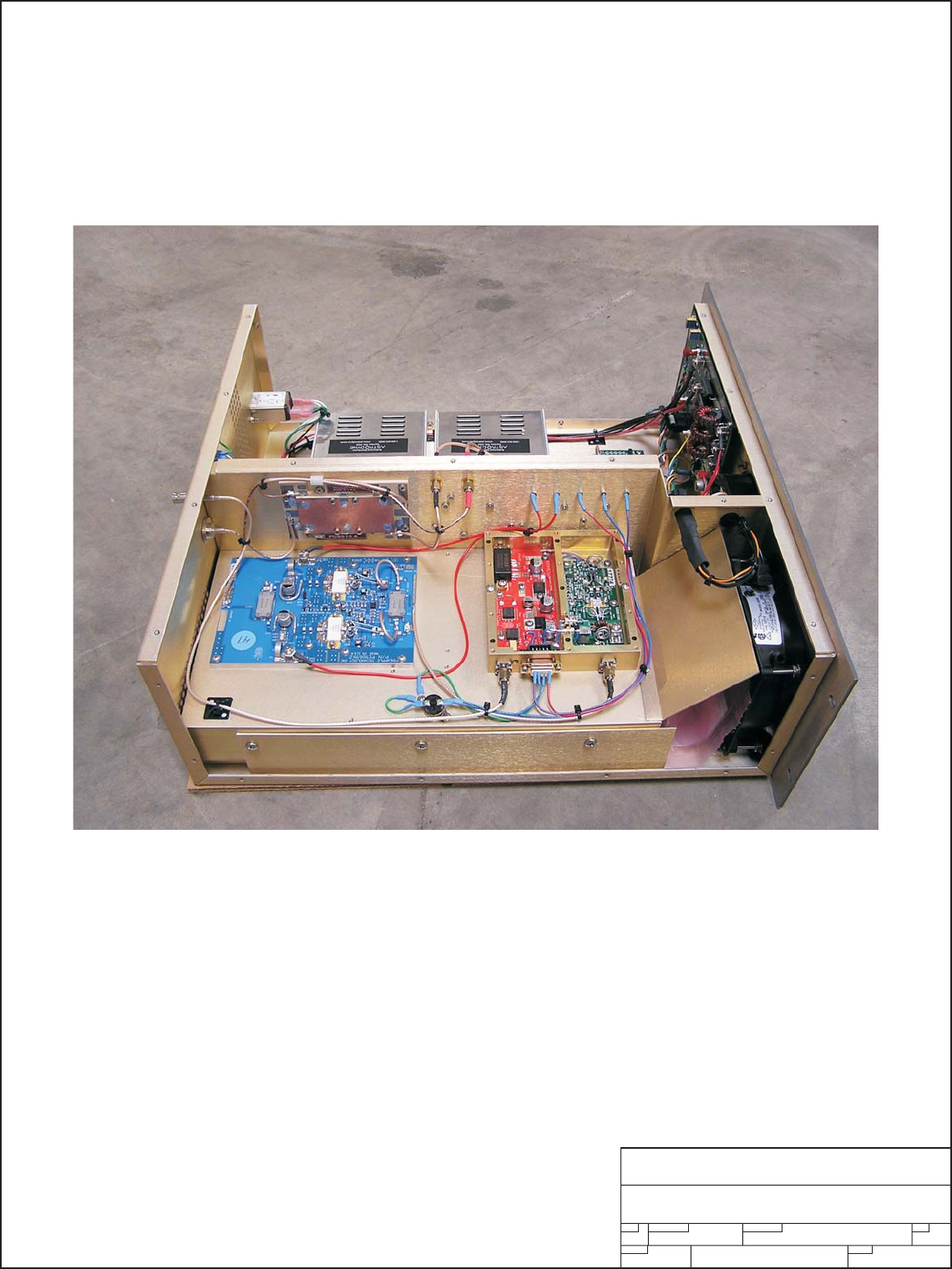
Pineapple Technology, Inc.
Rocklin, CA
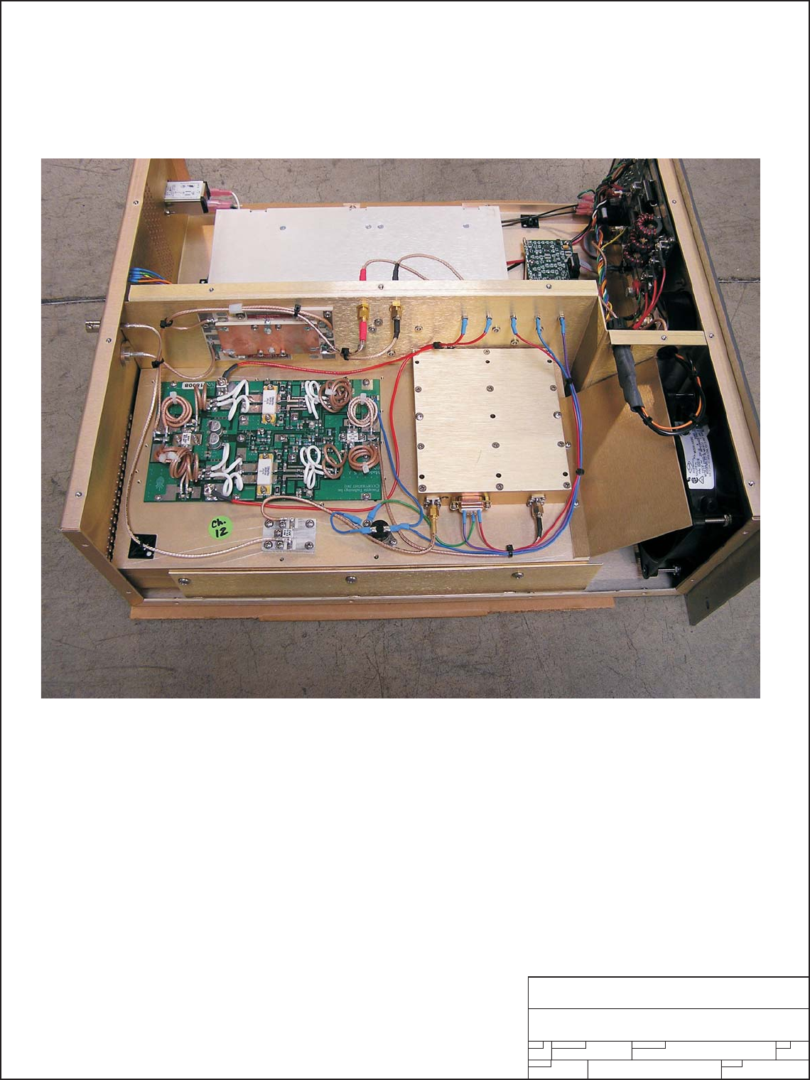
LTX Mainframe UHF
Internal View
SECTION VI - SCHEMATIC AND PARTS LISTS
SUB-SECTION A - LTX100U/LH/LV
Page 15
PINEAPPLE TECHNOLOGY, INC.
LTX100U/VL/VH Operating and Service Manual Vl -- SCHEMATICS AND PARTS LIST
A. LTX Mainframe VH Assy Tree
Item Qty Type P/N Title Detail
Top CAT LTX100VH LTX SERIES VHF HB 100 WATT
X
100 WATT
1 1 PL LTXMAINFRAME VH
F
LTX SERIES XMTR 100 W VHF H
B
BASIC UNIT
1 1 PS MF9529A LTX HEAT SINK HOLDER AL 090
2 1 PS MF9531A LTX FRONT PANEL 0125 AL W/PAINT AND SILK
3 1 PS MF9532A LTX CHASSIS 090 AL ALODYNE W/REAR SILK
4 1 PS MF9533A LTX AIR DAM DEFLECTOR 050 AL ALODYNE
5 1 PS MF9534A LTX TOP COVER O60 AL ALODYNE
7 1 PS MF9536 LTX100 VHF HIGH HEAT SINK STD PTI HS MATERIAL
10 1 PS PC9515 COUPLER GP COVER TMM3 012 USE ON ALL -30dB COUPLERS
12 1 PS PC9513 VHF HB -30 dB COUPLER TMM3 DUAL DIRECTIONAL
14 1 PS 660104 LTX MULTI-FUNCTION METER HOYT MODEL 3135 ANALOG MTR
15 1 PS AC3108 CIRCUIT BREAK/ ON/OFF SWIT
C
115 VAC 10 A RESETABLE
16 1 PS AC1003 FILTER, AC LINE 110/220 AC PLUG
17 1 PS 990200 FILTER, AIR DRY COMAIR FILTER/GUARD ASS,Y
18 1 PS 851035 FAN AC 115 100 CFM 115 VAC COMAIR-ROTRON MUFFIN XL AC MX2
A
19 1 PS CA5110 CABLE ASSEMBLY 10 WIRE 10 WIRE SOC TO SOC CONNECTOR
20 4 PS 480300 CON 2 PIN HEADER AMP A23837-ND
22 1 PS AC2010 DC POWER SUPPLY 115/220 VA
C
320 WATTS 27-31 VDC
23 6 PS INHOUSE_LABOR PTI LABOR LOADED
24 8 PS INHOUSE-ENG TES
T
ENG TESTING AND FIXIT LOADED
25 1 PL 1A0300 LTX100 METERING CIRCUIT FRONT PANEL ASSEMBLY
26 1 PL 1A0027 PWR MONITOR CK PC9052B CBR
27 1 PL 1A0035 PA STATUS BOARD PC9061H
28 1 PL 1A0026 VSWR/PWR DET BRD PC9051A
29 1 CAT DRV10-40 DRIVER AMP WITH ALC CKT PO 10 W
34 1 PS 990280 FINGER GUARD 6" FINGER GUARD 150MM METAL
35 1 PS 851030 PATRIOT AC FAN 110 V XL100 EXHAUSE FAN
36 1 PS 481501
A
URAL FEMALE PNL CONNECT
O
XLR TYPE 3 PIN
LTX100VH LTXMainframe Assy Tree
Page 16
SIZE FSCM NO.
SCALE SHEET
DWG NO. REV
Pineapple Technology, Inc.
Rocklin, CA
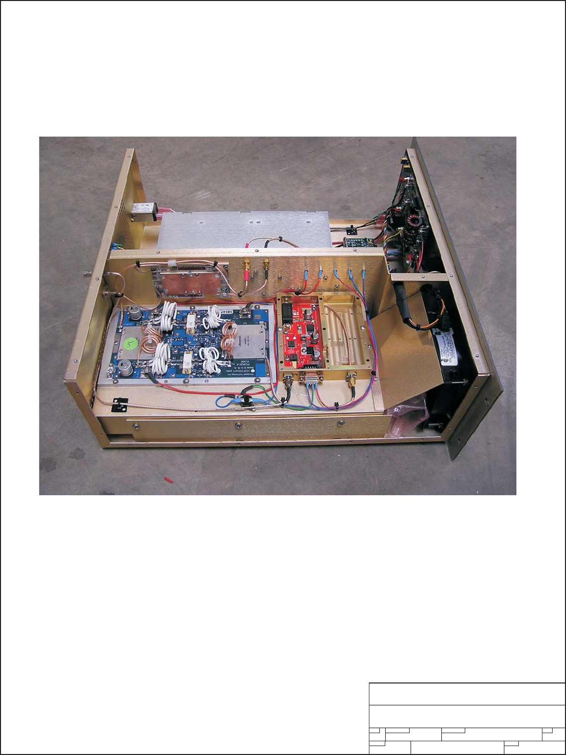
LTX Mainframe High VHF
Internal View
SECTION VI - SCHEMATIC AND PARTS LISTS
SUB-SECTION A - LTX100U/LH/LV
Page 17

PINEAPPLE TECHNOLOGY, INC.
LTX100U/VL/VH Operating and Service Manual Vl -- SCHEMATICS AND PARTS LIST
A. LTX Mainframe VL Assy Tree
Item Qty Type P/N Title Detail
Top CAT LTX100VL LTX SERIES XMTR VHF LOW BA
N
100 WATTS
1 1 CAT LTXMAINFRAME VH
F
LTX SERIES XMTR 100 W VHF L
B
BASIC UNIT
1 1 PS MF9529A LTX HEAT SINK HOLDER AL 090
2 1 PS MF9531A LTX FRONT PANEL 0125 AL W/PAINT AND SILK
3 1 PS MF9532A LTX CHASSIS 090 AL ALODYNE W/REAR SILK
4 1 PS MF9533A LTX AIR DAM DEFLECTOR 050 AL ALODYNE
5 1 PS MF9534A LTX TOP COVER O60 AL ALODYNE
8 1 PS MF9537 LTX100 VHF LOW BAND HEAT S
I
STD PTI HS MATERIAL
10 1 PS PC9515 COUPLER GP COVER TMM3 012 USE ON ALL -30dB COUPLERS
13 1 PS PC9512 VHF LB -30 dB COUPLER TMM3
0
DUAL DIRECTIONAL
14 1 PS 660104 LTX MULTI-FUNCTION METER HOYT MODEL 3135 ANALOG MTR
15 1 PS AC3108 CIRCUIT BREAK/ ON/OFF SWIT
C
115 VAC 10 A RESETABLE
16 1 PS AC1003 FILTER, AC LINE 110/220 AC PLUG
17 1 PS 990200 FILTER, AIR DRY COMAIR FILTER/GUARD ASS,Y
18 1 PS 851035 FAN AC 115 100 CFM 115 VAC COMAIR-ROTRON MUFFIN XL AC MX2
A
19 1 PS CA5110 CABLE ASSEMBLY 10 WIRE 10 WIRE SOC TO SOC CONNECTOR
20 4 PS 480300 CON 2 PIN HEADER AMP A23837-ND
22 2 PS AC2010 DC POWER SUPPLY 115/220 VA
C
320 WATTS 27-31 VDC
23 6 PS INHOUSE_LABOR PTI LABOR LOADED
24 8 PS INHOUSE-ENG TES
T
ENG TESTING AND FIXIT LOADED
25 1 PL 1A0300 LTX100 METERING CIRCUIT FRONT PANEL ASSEMBLY
26 1 PL 1A0027 PWR MONITOR CK PC9052B CBR
27 1 PL 1A0035 PA STATUS BOARD PC9061H
28 1 PL 1A0026 VSWR/PWR DET BRD PC9051A
29 1 CAT DRV10-40 DRIVER AMP WITH ALC CKT PO 10 W
34 1 PS 990280 FINGER GUARD 6" FINGER GUARD 150MM METAL
35 1 PS 851030 PATRIOT AC FAN 110 V XL100 EXHAUSE FAN
36 1 PS 481501
A
URAL FEMALE PNL CONNECT
O
XLR TYPE 3 PIN
LTX100VL LTXMainframe Assy Tree
Page 18
SIZE FSCM NO.
SCALE SHEET
DWG NO. REV
Pineapple Technology, Inc.
Rocklin, CA
LTX Mainframe Low VHF
Internal View
SECTION VI - SCHEMATIC AND PARTS LISTS
SUB-SECTION A - LTX100U/LH/LV
Page 19
SIZE FSCM NO.
SCALE SHEET
DWG NO. REV
Pineapple Technology, Inc.
Rocklin, CA
LTX100 Mainframe Assembly
A
1
B
1:1
Directional
Coupler
CAL
CAL
ATT
ATT
R
F
AC Inlet
110 VAC
DC Output
Driver
M
+DC
RF IN
PA Fan
PS1
P/S
110VAC
ON\OFF
SW
PA
M
+DC
RF IN
DC Metering
and
DC Monitoring
1A0035
RF Deck
110 VAC
RF
DB9
From
RF Output
Monitor Tap
RF
RF Probe
FWD Pwr P1
P2
P3
Gnd P4
Shutdown P5
P6
RFLD Pwr P7
ALC P8
+8 VDC P9
LTX100U Ch 14 - 69
Channel Driver
Direct’l
Coupler
PA P/S
UDR10E
PC9512
PC9513
PC9514
U250LD Note1
Note1
Note1
VH250LD
VL500A
UDR10E
UDR10E
Ch7-13
Ch2-6
LTX100VH
LTX100VL
Page 20
SIZE FSCM NO.
SCALE SHEET
DWG NO. REV
Pineapple Technology, Inc.
Rocklin, CA
BPU150 Band Pass Filter
No Serviceable Parts
SECTION VI - SCHEMATIC AND PARTS LISTS
SUB-SECTIONC-LTX100U/VH/VL
Page 21
SIZE FSCM NO.
SCALE SHEET
DWG NO. REV
Pineapple Technology, Inc.
Rocklin, CA
Low VHF Bandpass Filter
CIRCUIT DIAGRAM
No Serviceable Parts
SECTION VI - SCHEMATIC AND PARTS LISTS
SUB-SECTIOND-LTX100U/VH/VL
Page 22

Section VII
Recommended
Routine
Maintenance

PINEAPPLE TECHNOLOGY, INC.
LTX100U/LH/LV Operating and Service Manual VII -- ROUTINE MAINTENANCE
V
II --- ROUTINE MAINTENANCE
Routine Maintenance on the transmitter is very simple and straight forward. PTI recommends the following
steps to ensure long and eliable trouble-free service.
SCHEDULE: DAILY OR WEEKLY SERVICE
1. Check output power level to ensure that the meter is reading in the GREEN. If the level has changed
adjust the output level to 100% using the modulator output level adjust.
2. Check and record all meter readings in the station log.
3. Review readings and compare to history for possible variation that could indicate problems.
4. Check the air inlet filter and clean if necessary. If it looks dirty, it is dirty. Snap off the front grill an
d
wash the filter with light detergent and dry thoroughly before reinstalling. DO NOT use oils on the
filter.
5. Clear any items placed in front or in the rear of the transmitter that may restrict air flow.
SCHEDULE: MONTHLY +
A
ll the items listed above with air filter cleaning necessary.
NOTE: REPLACEMENT FILTERS ARE AVAILABLE THRU MOST ELECTRONIC DISTRIBUTERS.
LOOK FOR COMAIR ROTRON P/N: 020172
FACILITIES
●Clean all air inlet filters and exhaust outlets to ensure that the transmitter is getting clean
unobstructed airflow.
●Perform recommended service on air condition systems.
●Rodent traps or baits should be renewed to keep the facilities clear of these pests which can
cause damage to the transmitter.
Page 23

Section VIII
Adjustments
and
Tuning

PINEAPPLE TECHNOLOGY, INC.
LTX100U/VH/VL Operating and Service Manual VIII -- ADJUSTMENTS AND TUNING
V
III --- ADJUSTMENTS AND TUNING
The LTX100U/VH/VL is a new series of analog transmitters offered by Pineapple Technology, Inc. The
latest in LDMOS device and circuit technology are employed to ensure reliable and serviceabl
e
operation for many years.
There are very few adjustments necessary to maintain full service condition. Typically the gai
n
adjustment shown in the initial Transmitter Turn-On Procedure (Section IV) of this manual should
require minimal attention. The front meter panel has been set up so that 100% indication in
Forward Power is equivalent to 100W peak sync power.
The transmitter output must remain on the channel licensed by the FCC and in accordance
with the supplied band pass filter and set up on the exciter/modulator.
Page 24

Section IX
Problem
Solving
&
Troubleshooting
PINEAPPLE TECHNOLOGY, INC.
LTX100U/VH/VL Operating and Service Manual IX -- PROBLEM SOLVING/TROUBLE SHOOTING
IX - PROBLEM SOLVING & TROUBLE SHOOTING
(
Pa
g
e 1of 2
)
The LTX100U/VH/VL is a "MODULAR ASSEMBLY" where most of the sub-assemblies can be
removed and or re
p
laced as necessar
y
as necessar
y
to maintain full service. To service this transmitter,
it is best to become familiar with the various sub-assemblies b
y
reviewin
g
the transmitter block dia
g
ram
and it's associated subs shown in the introduction. An
y
work
p
erformed on a transmitter licensed b
y
the FCC must be
p
erformed b
y
q
ualified
p
ersonnel.
FAILURE ANALYSIS STARTS WITH THE FOLLOWING ASSUMPTIONS:
1. The transmitter is connected to an AC source which is within the s
p
ecified volta
g
e ran
g
e
and has am
p
le
p
ower to run the transmitter.
2. The antenna has been checked out and a
p
ro
p
er match has been verified.
3. The room tem
p
erature is < +35 de
g
rees Celsius
(
+95 de
g
rees Fahrenheit
)
4. There are no restrictions in the air flow in or out of the buildin
g
.
5. The video and aural si
g
nals to the modulator com
p
l
y
with stated s
p
ecifications.
CHECKING THE WARNING LIGHTS
There are several warnin
g
si
g
nals visible on the front of the transmitter that will alert the technician
of
p
ossible
p
roblems. When viewed from the front, all the li
g
hts should be GREEN indicatin
g
normal
o
p
eration. An alert si
g
nal is indicated b
y
a RED li
g
ht. We will focus on RED alert si
g
nals in this section
.
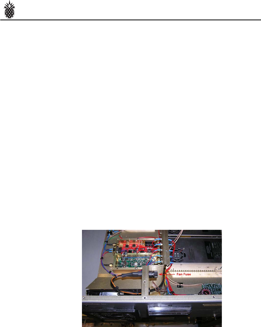
LTX Mainframe Assembl
y
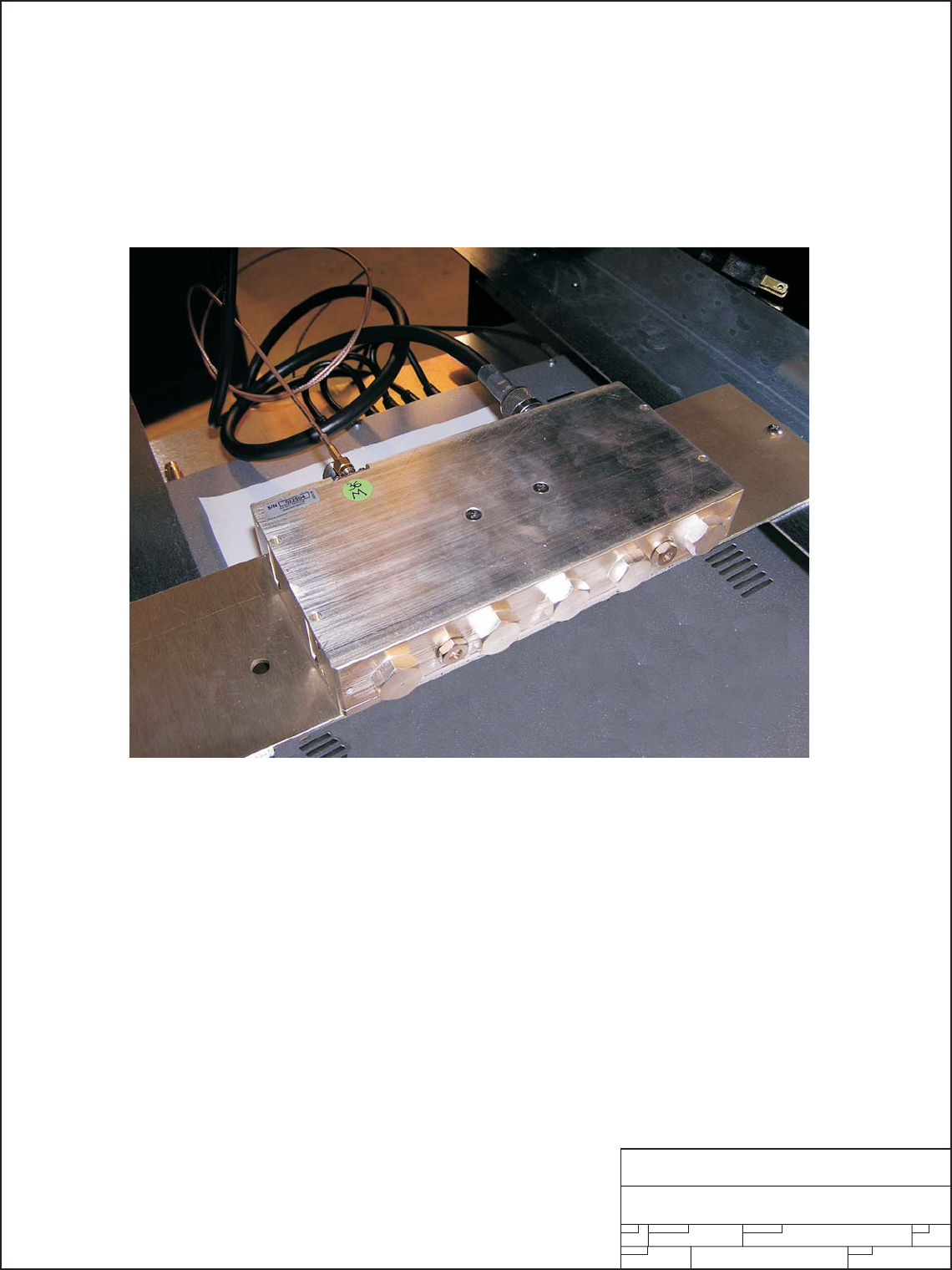
FAN FAULT RED indicates that the fuse su
pp
l
y
in
g
AC to the fan has failed. The fus
e
is located
j
ust inside the front
p
anel near the to
p
. See Fi
g
. 1 for location.
CHECK: FUSE AND/OR FAN
Fi
g
. 1
Page 25

PINEAPPLE TECHNOLOGY, INC.
LTX100U/VH/VL Operating and Service Manual IX -- PROBLEM SOLVING/TROUBLE SHOOTING
IX - PROBLEM SOLVING & TROUBLE SHOOTING (Page 2of 2)
TEMP FAULT RED indicates over tem
p
erature of PA or Hi
g
h VSWR
If Hi
g
h VSWR, the li
g
ht will c
y
cle 10 seconds OFF and 2 seconds ON
Put transmitter in STANDBY. Investi
g
ate antenna installation and
connections, check transmission lines and connections. Check
that transcoder u
p
converter is on fre
q
uenc
y
.
If Hi
g
h Tem
p
erature, the li
g
ht will c
y
cle OFF for several minutes then ON
for several minutes.
Check: Room tem
p
erature
Check: For Blocked Air Filter
Check: For Blocked Air Flow
Check: Transcoder Drive level. Verif
y
out
p
ut
p
ower is at 100% or less.
NOTE: If the AC Power is ON and all LED's are OFF and all meter readings are Zero (0) the DC Powe
r
Supply may cycle on and off if the internal fan has failed or Hi temp has failed. Th
e
internal DC supply may have failed and needs replacing
.
Page 26

Section X
Warranty

PINEAPPLE TECHNOLOGY, INC.
LTX100U/VH/VL Operating and Service Manual X -- WARRANT
Y
X -- WARRANT
Y
The WARRANTY provided by Pineapple Technology, Inc. (PTI) on this transmitter is detailed below.
It should be noted that some of the equipment sub-systems have warranty coverage by the orginal
manufacture that differs from the standard warranty provided by PTI Warrantydetails on equipment falling
into this category may be found in the Manufacturers instruction manual provided with the transmitter.
In all cases, replacement units of this equipment are normally in stock at PTI for quick turn service
support to our customers during the PTI Standard Warranty period.
STANDARD WARRANT
Y
Seller warrants that each Product sold by it is free of defects in materials and workmanship. Seller's
obligation under said warranty continues for a period of one (1) year from date of shippment. Repairs or
replacement of defective parts shall be the sole and exclusive remedy under waranty, at Seller option,
provided that Seller may, as an alternative, elect to refund an equitable portion of the purchase price
of the product. THIS WARRANTY IS EXPRESSLY IN LIEU OF AND EXCLUDES ALL OTHER
EXPRESS OR IMPLIED WARRANTIES, INCLUDING BUT NOT LIMITED TO WARANTIES OF
FITNESS FOR A PARTICULAR PURPOSE, USE, OR APPLICATION, AND ALL OTHER OBLIGATION
S
OR LIABILITIES ON THE PART OF THE SELLER, UNLESS SUCH OTHER WARRANTIES
OBLIGATIONS OR LIABILITIES ARE EXPRESSLY AGREED TO IN WRITING BY SELLER.
WARRANTY REPLACEMENT AND REPAIR
S
A
ll claims under warranty must be made promptly after occurrence of circumstances giving rise to thereto
and must be received within the applicable warranty period by seller or its authorized representatives.
Such claims must be documented on a PTI* Field Failure Report with a full description of the circumstances
giving rise to the claim. Before any products are returned for repair and/or adjustment, written authorization
form seller or its authorized representative for the return and instructions as to how and where these
products should be shipped must be obtained. This is to include a Return Authorization (RA) number
provided by the seller or authorized representative, this must accompany ALL returns. Any product
returned to the seller for the examination shall be sent prepaid via the means of transportation indicated as
acceptable by seller. Seller reserves the right to reject any warranty claim not promptly reported and any
claim on any item that has been altered, i.e. circuit modifications, components removed, or has been shipped
by non acceptable means of transportation. When a product has been returned for examination and inspection,
or for any other reason, customer shall be responsible for all damage resulting from improper packaging or
handling, and for loss in transit, notwithstanding any defect or nonconformity in the product. In all cases the
seller has sole responsibility for determining the cause and nature of the failure, and the Seller's
determination with regard thereto shall be final. If it is found that Seller's Product has been returned without
cause and is still serviceable, customer will be notified and the Product returned at its expense, in addition,
a charge for testing and examination may, in Sellers sole discretion be made on Products so returned.
* A field Failure Report is included at the end of this manual - Additional Field Failure Reports can be obtained by calling
Pineapple Technology, Inc. at (916) 652-1116 or you may download one from our website at www.ptibroadcast.com
in the Warranty section.
Page 27