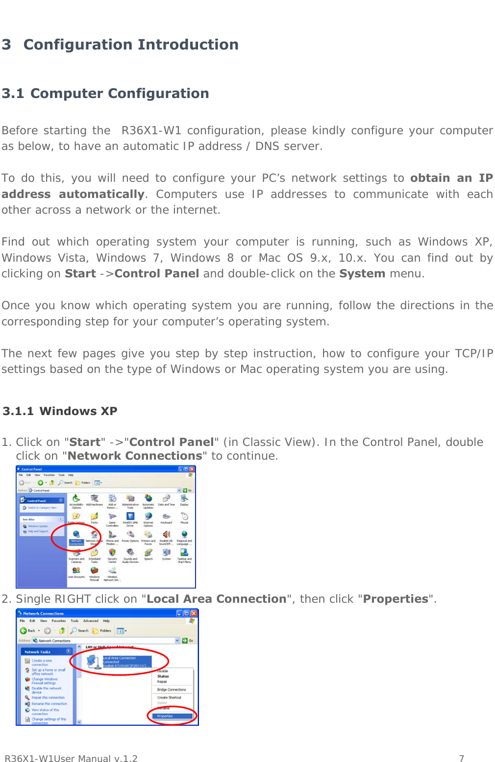
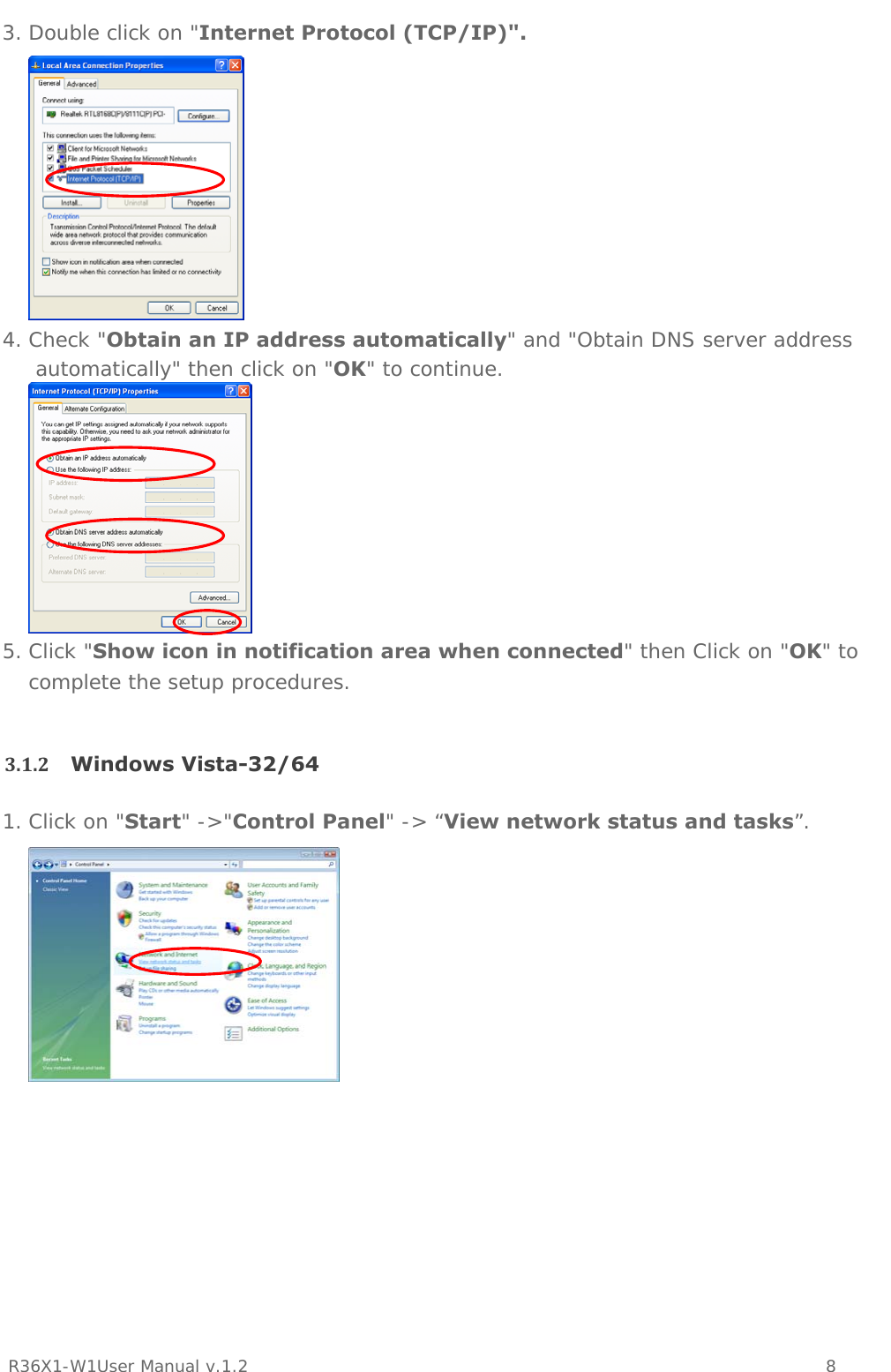
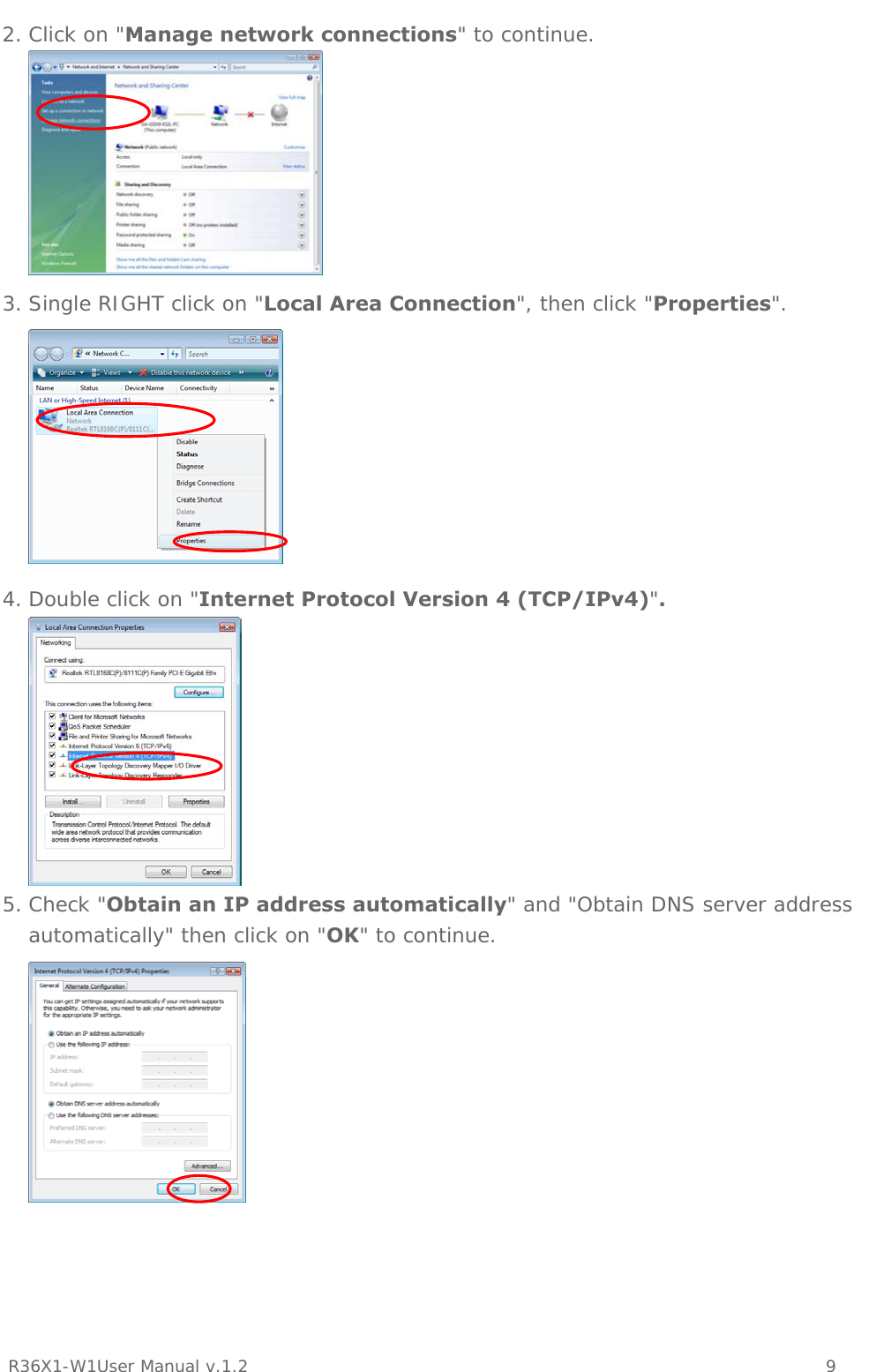
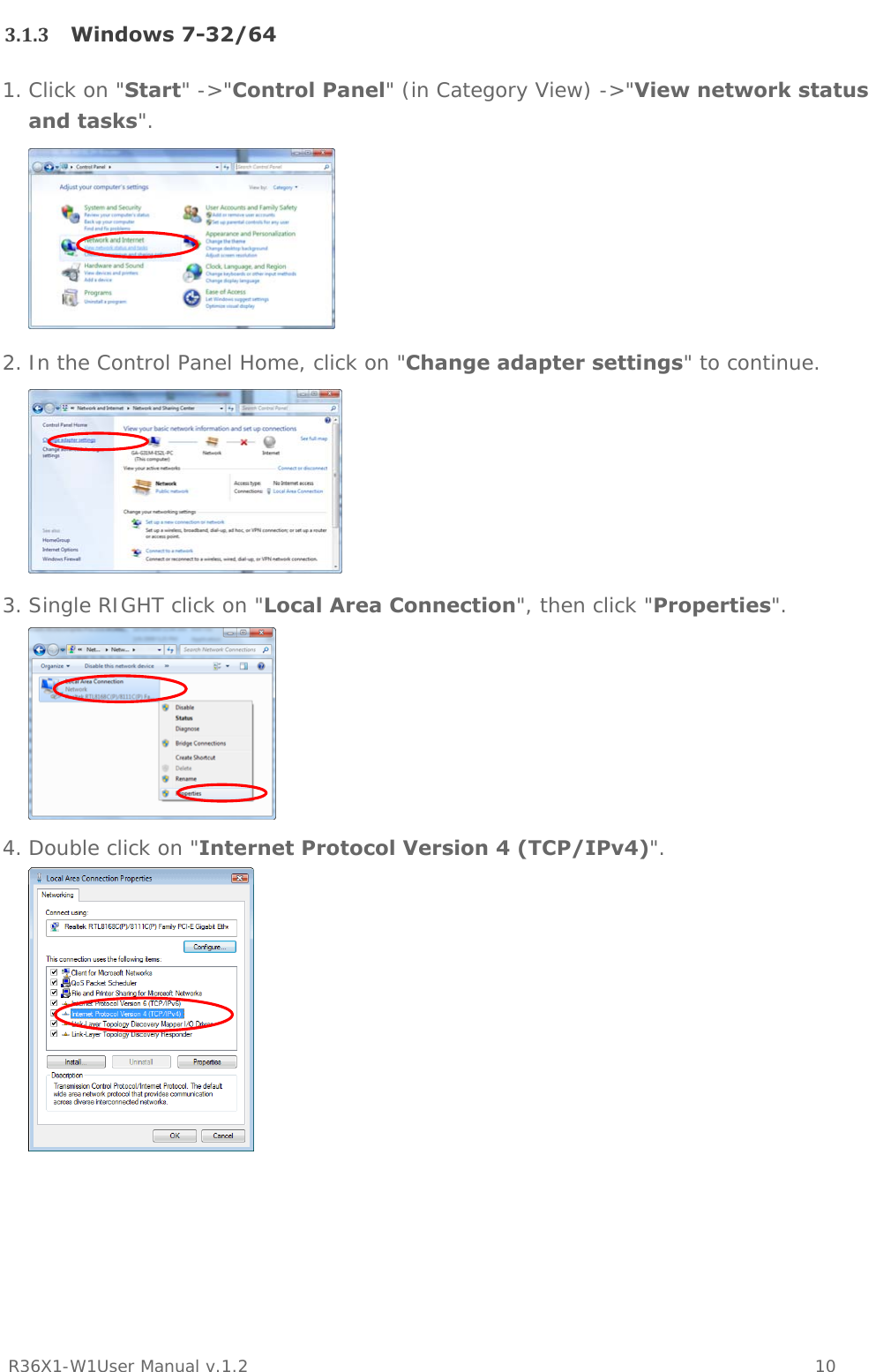
Ping Communication AS R36X1 FIBER GATEWAY (Router) User Manual Generic R36x1 W1 User Manualx
Ping Communication AS FIBER GATEWAY (Router) Generic R36x1 W1 User Manualx
UserManual.wiki
>
Ping Communication AS
>
R36X1 User Manual
Manual
Navigation menu
Upload a User Manual
Namespaces
Wiki Guide
HTML
PDF
Info
Views
User Manual
Discussion / Help
Navigation

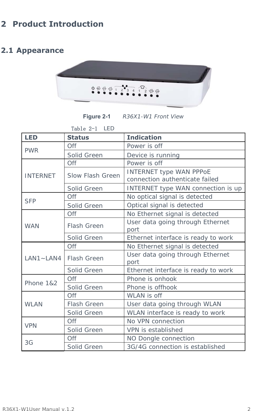
![Preface Brief Introduction This manual provides technical information on how to configure and operate application for your R36X1-W1 unit. Chapter 1: Provides an overview of R36X1-W1 Chapter 2: Introduces the product Chapter 3: Introduces the configuration via WEB-based Management Intended Audience System administrators, Network engineers and Maintenance technicians. Style Convention Table 1 Style convention used in this manual Style Meanings \ Multi-level catalogs or menus are separated by ‘\’ character. For instance “file\new\directory” means the menu item “directory” in menu “new” which in turn in the menu “file”. Used to highlight important area in diagrams. <> Indicates the input data from operating terminal. [] Indicates one parameter configuration or a function. { XX | XX } Indicates a syntax of CLI command options, multiple command options in one “{}”, separated by “|”, means exclusive single selection. host(italic) Indicates user specified parameters. e.g. for command: tftp host {get | put} {sys | cfg} filename The host and filename should be replaced by user specified real parameters, such as: tftp 138.0.0.1 get sys sysfile.bin Table 2 Convention for Mouse Operation Operation Meanings Click Press and release a mouse button quickly Double click Quickly press and release a mouse button twice Drag Press a mouse button and move the mouse Table 3 Convention for Keyboard Operation Style Meanings Ctrl + C “+”means an operation which presses down several keys in the keyboard in the same time. E.g. “Ctrl + C” means 。press down the key of “Ctrl” and “C” in the same time](https://usermanual.wiki/Ping-Communication-AS/R36X1/User-Guide-2577506-Page-3.png)
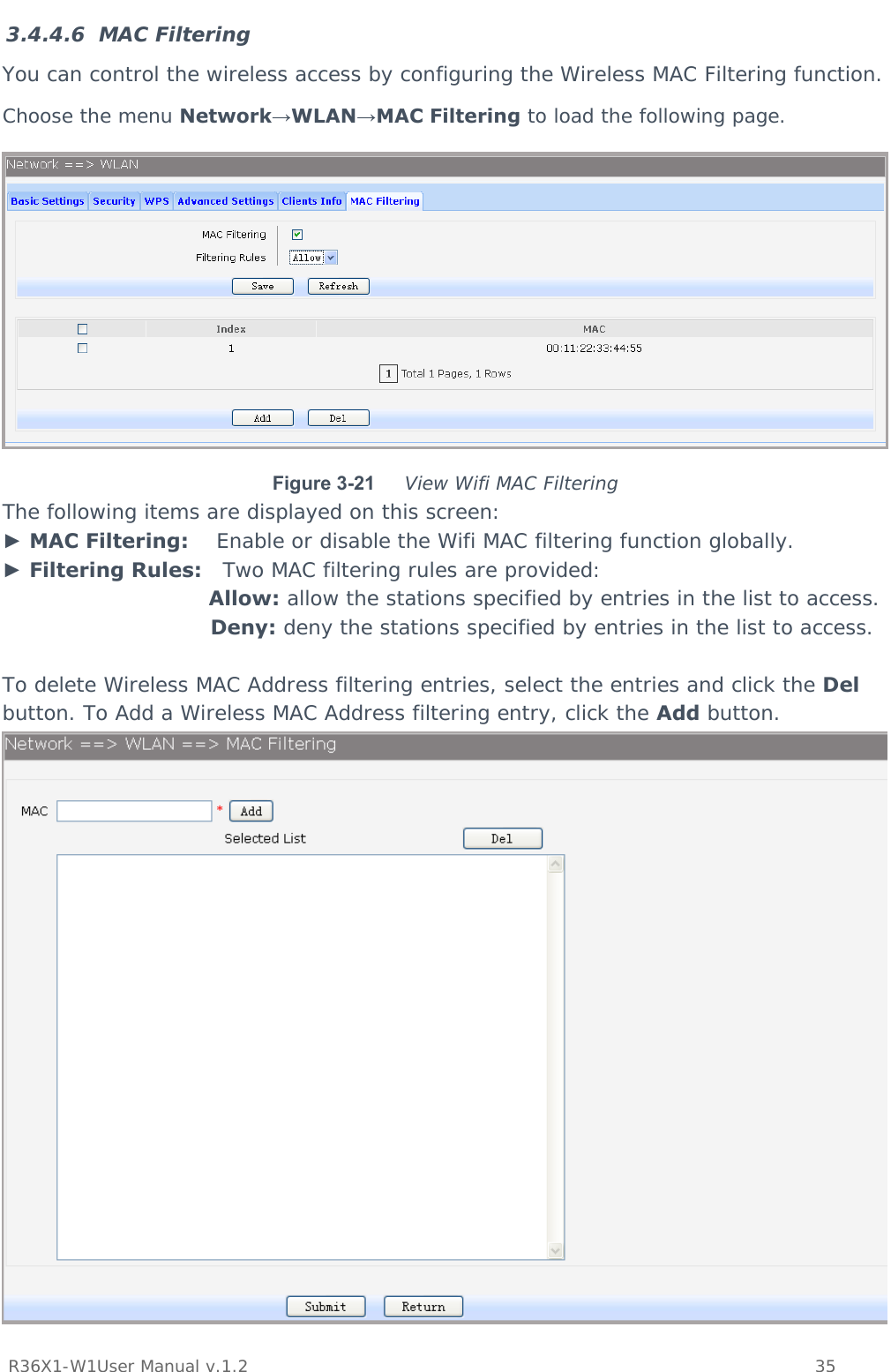

![R36X1-W1User Manual v.1.2 90 digit timeout expires. If the number length of suited route item is indefinite, there are 3 ways to determine whether the digits is enough, press pound(#) key, timeout expires or digitmap comparing. If digits dialed partly matching with digitmap patterns, continue waiting of number receiving. If they match, send the number immediately. If not, send the number immediately too, in order to play the prompts. Table 3-1 Digitmap Characters Character Description ~0 9 Indicates specific digits in a telephone number expression. X Wildcard, matches any digit, excluding “#” and “*”. * Digit star # Digit pound - Connects the start and the end of a range [] Indicates the a range of numbers(not letters). . Matches an arbitrary number of occurrences of the preceding digit, including 0. | Indicates a choice of matching expressions (OR). T Inter-digit timeout expiresS Short timer expires, usually place at the middle of an expression Digitmap Example: 8XXXXXXX|1[0-24]0|2[18].3|3XXSXX|[0-9*#][0-9*#][0-9*#].#|[0-9*#].T “8XXXXXXX” denotes numbers start with 8, the length is 8. “1[0-24]0” denotes numbers include 100, 110, 120 and 140. “2[18].3” denotes numbers that start with 2 and end with 3, there can be arbitrary length of 1 or 8 after the first digit 2. 23, 213, 2183 is matched. “3XXSXX” denotes numbers start with 3, the length can be 3 or 5. If the short timer configured expires between the third digit and the fourth digit, the number will be sent. “[0-9*#][0-9*#][0-9*#].#” denotes numbers end with #, and the length is no less than 2. “[0-9*#].T” denotes any number that dialing time out. Choose the menu VOIP Service→Digitmap to load the following page.](https://usermanual.wiki/Ping-Communication-AS/R36X1/User-Guide-2577506-Page-95.png)