Pioneer K077 Pedaling Monitor Sensor User Manual Short term Confindetial
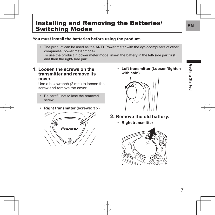
Pioneer Corporation Pedaling Monitor Sensor Short term Confindetial
Pioneer >
Contents
- 1. (Short term Confindetial)User Manual
- 2. (Short term Confindetial)User Manual_Safety Notice
(Short term Confindetial)User Manual

![3ENIntroductionFeaturesThis product is a sensor system that analyzes the pedaling of a bicycle in real time. It calculates the direction and intensity of the force acting on the pedals and calculates pedaling efciency.Description of componentsStrain gauge unit: • Detects the strain on the crank and calculates the direction and intensity of the force on the crank.Magnet: • Used to detect the angle of rotation.Transmitters: • Send information from the strain gauge unit and the magnet to the Cyclocomputer.Switching modesThe switch in the right transmitter changes the system to the following modes.Pedaling mode• : Used in combination with the Cyclocomputer SGX-CA500/CA900. This mode calculates pedaling efciency and maximizes the functionality of the product.Power meter mode• : Used with a Cyclocomputer that supports ANT+™.ManualsThe product’s manuals consist of this User’s Manual, an Installation Manual, and Important Information for the User.User’s Manual:• Explains how to pair the product with the Cyclocomputer and calibrate the sensors.Installation Manual:• [For American Users] http://www.pioneerelectronics.com[For Canadian Users] http://www.pioneerelectronics.ca[For European Users] http://www.pioneer.euExplains details about handling methods. The product installation methods (for dealers) are also described as references.Important Information for the User:• Important Information for the User provides detailed information related to safety.](https://usermanual.wiki/Pioneer/K077.Short-term-Confindetial-User-Manual/User-Guide-2182597-Page-3.png)
![10ENPairing / CalibrationPairing with the CyclocomputerThis section describes how to pair the installed SGX-PM900 pedaling monitor sensors on your bicycle to the SGX-CA500/CA900 Cyclocomputer.This pairing procedure may be different if you are using a cyclocomputer other ●than the Pioneer SGX-CA500/CA900. Please refer to your cyclocomputer’s owner manual for sensor pairing.1. Check the sensor modes.Check that the right transmitter and the left transmitter are in "Pedaling mode."See page 8 to switch the modes.• 2. Tap the [Sensors] icon in the home screen of the SGX-CA500/CA900.The sensor list screen opens.3. Rotate the bicycle’s crank set three rotations to start the transmitter.Pair with the Cyclocomputer within • 5 minutes after the transmitters are activated.After the transmitters are activated, it • may take more than 1 minute to pair with the Cyclocomputer.4. Tap [Connect New] in the sensor list screen of the SGX-CA500/CA900.The sensor connection menu opens.5. Tap [Device Type] and then [Pedaling Monitor R].For the left transmitter, tap [Pedaling • Monitor L].If multiple sensors are activated, • bring the main unit closer to the sensor, or specify the device number to pair the sensor you want to pair.Refer to the User's Guide of the Cyclocomputer SGX-CA500/CA900 regarding how to specify a device number to pair a sensor.Pairing / Calibration](https://usermanual.wiki/Pioneer/K077.Short-term-Confindetial-User-Manual/User-Guide-2182597-Page-10.png)
![11ENPairing / CalibrationPairing with the Cyclocomputer6. Tap [Search].The search for the sensor starts.A [Searching. Please wait.] message appears.7. Check the information about the sensor.Information about the sensors appears when the sensors are found.Check the following items.[Device Number]• Make sure that the device number is the same as the device number of the transmitter.[Error Rate]• Make sure that “OK” is displayed.The device numbers are printed on • the right junction box and on the side of the left sensor. Refer to the Installation Manual for details.If the numbers that are displayed on • [Device Number] are different from the transmitter device numbers, specify the device numbers to pair with the sensor. Refer to the User’s Guide of the Cyclocomputer SGX-CA500/CA900 regarding how to specify a device number to pair a sensor.If “NG” is displayed in the [Error • Rate] area, the information from the sensor is not being received correctly because transmission conditions are bad. Make sure that the sensor you are pairing is activated, then bring the SGX-CA500/CA900 closer to the sensor and perform the pairing operation again.You may not pair with the sensor • due to the inuence of the 2.4 GHz frequency band. If “NG” is displayed even if the SGX-CA500/CA900 is moved closer to the sensor and paired with it, try again someplace where there is no interference from microwaves, radio waves, or wireless equipment.Pairing of the right transmitter is completed. Then, pair the left transmitter.](https://usermanual.wiki/Pioneer/K077.Short-term-Confindetial-User-Manual/User-Guide-2182597-Page-11.png)
![12ENPairing / CalibrationCalibrating the SensorsThis section describes how to use the Cyclocomputer SGX-CA500/CA900 to calibrate the zero point of the pedaling monitor sensor that is installed on the bicycle.The right-side pedaling monitor sensor is used as an example in this description. The • procedure to calibrate the left side is the same as for the right side.Getting Ready1. Stop the bicycle on a at safe place.Calibrating the Zero Point1. Position the crank arm so it is perpendicular to the ground.2. Tap the [Sensors] icon in the home screen of the SGX-CA500/CA900.The sensor list screen opens.3. Tap [Pedaling Monitor R] and then [Calibration (Zero)].4. Tap [Start Calibration].The calibration starts.If the calibration is successful, “Success” appears in the [Result] eld.If “Failure” is displayed, the sensor may be calibrated in an unstable condition causing the crank to be moving during the calibration. Calibrate again with the crank stopped.This product has a correction • function for the zero point uctuation caused by varying temperatures. The accuracy of this function improves when the sensor is calibrated in different temperatures.This function cannot measure correctly if you calibrate or check the sensor before it is acclimated to the outside temperature.](https://usermanual.wiki/Pioneer/K077.Short-term-Confindetial-User-Manual/User-Guide-2182597-Page-12.png)
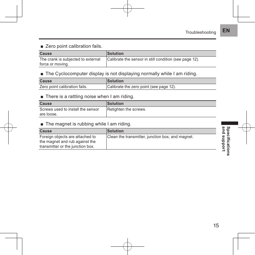
![13ENPairing / CalibrationCalibrating the SensorsChecking the Zero Point1. Position the crank arm so it is perpendicular to the ground.2. Tap [Pedaling Monitor R] in the sensor list screen of the SGX-CA500/CA900.3. Conrm the value in [Force Preview].Make sure that the [Tangential Direction Force] and [Radial Direction Force] values are as shown here.Tangential Direction Force: 0 ± 3 N• Radial Direction Force: 0 ± 3 N• Calibration of the right side is nished. Calibrate the left side in the same way.Calibrating in Power Meter ModeWhen calibrating the sensors in power meter mode, position the crank arm so it is perpendicular to the ground, do the procedure to the left and right sides together. Refer to the User’s Manual of the Cyclocomputer you are using for details.](https://usermanual.wiki/Pioneer/K077.Short-term-Confindetial-User-Manual/User-Guide-2182597-Page-13.png)