Pioneer Scsi 2 Users Manual 2_CD_31–
If not then 31636562SCSI-2RefManV31 Manual: ://www.pioneerelectronics.com/pio/pe/images/portal/cit_3424/31636562SCSI-2RefManV31
SCSI-2 to the manual 4aa1c3ad-9c41-414a-a23f-a9cd52d0a593
2015-01-26
: Pioneer Pioneer-Scsi-2-Users-Manual-333720 pioneer-scsi-2-users-manual-333720 pioneer pdf
Open the PDF directly: View PDF ![]() .
.
Page Count: 189 [warning: Documents this large are best viewed by clicking the View PDF Link!]

CD-ROM
SCSI-2 Command Set
Reference Manual
Version 3.1
(OB-U0077C)
June 26, 1997
Pioneer Electronic Corporation
Pioneer New Media Technologies, Inc.

CD-ROM
SCSI-2 Command Set
Reference Manual
Version 3.1
(OB-U0077C)
This manual is copyrighted with all rights reserved. No part of this document may be reprinted,
reproduced, translated or utilized in any form or by any means now known or hereafter invented
including, but not limited to, any electronic, mechanical, photocopying and recording or information
storage and retrieval system means, without the express written permission from Pioneer Electronic
Corporation or its affiliates.
Every effort has been made to ensure that the information in this manual is accurate. Pioneer is not
responsible for printing or clerical errors.
Information in this document is subject to change without notice.
Specifications and design are subject to improve or be changed without notice.
Copyright © 1997 Pioneer Electronic Corporation, Pioneer New Media Technologies, Inc.
Document No. SCSI2CD31S001-0697
Simultaneously printed in Japan and the United States of America.
Mention of third-party products is for informational purposes only and contributes neither an
endorsement nor a recommendation. Pioneer assumes no responsibility with regard to the performance or
use of these products.
No investigation has been made of common-law trademark rights in any word. Words that are known to
have current registrations are shown with an initial capital. Many, if not all, hardware and/or software
products referenced in this manual are identified by their trade names. Most, if not all, of these
designations are claimed as legally protected trademarks by the companies that make the product. It is
not Pioneer’s intent to use any of these names generically and cautions the reader to investigate any
claimed trademark before using it for any purpose other than to refer to the product to which the
trademark is attached.
Pioneer makes no warranty of any kind, expressed or implied, about the contents of this manual, the
merchantability of the product or the product’s fitness for any particular purpose.
Every precaution has been taken in the preparation of this manual. Although we tried to thoroughly
check that all instructions in this manual are accurate and correct, Pioneer can not be and is not
responsible, in whole or in part, for any damage or loss to your data and/or equipment that results from
your use of this document or from any information contained herein including, but not limited to, any
errors, omissions or typos that may have resulted in an incorrect operation or installation.
FCC INFORMATION
The equipment described in this manual has been tested and found to comply with the limits for a Class
B digital device in accordance with the specifications in Part 15 of FCC rules. These specifications are
designed to provide reasonable protection against radio and television reception interference in a
residential installation. There is no guarantee that interference will not occur in a particular installation.
To determine if your CD-ROM drive is causing interference, turn the drive off. If the interference stops,
it was most likely caused by the drive. To eliminate the interference, you may try one or more of the
following corrective measures:
•verify the cables and connectors between components are shielded.
•increase separation between the drive and components.
•connect the drive into an outlet or circuit different from that which the components are
connected.
•consult dealer or experienced radio/television technician for help.
The Federal Communications Commission offers a handbook that may help you with eliminating
interference. The handbook is titled Interference Handbook (stock number 004-000-00493-1) and may
be ordered from the U.S. Government Printing Office, Washington, D.C. 20402.
WARNING: Any changes or modifications to this product that are not authorized by Pioneer could void
the FCC Certification and negate the user’s authority to operate the equipment.
DOC CLASS B COMPLIANCE
This digital apparatus does not exceed the Class B limits for radio noise emissions from digital apparatus
set out in the radio interference regulations of the Canadian Department of Communications.
- -
i
Table of Contents
LIST OF TABLES ..............................................................................................................................iv
REVISION HISTORY......................................................................................................................viii
1. PREFACE.................................................................................................................................... 1
1.1 DRM/DR-U Series......................................................................................................................1
1.2 Drives Supported by this Manual ................................................................................................3
1.3 SCSI Protocol .............................................................................................................................4
1.3.1 Command Link/Control Field........................................................................... 4
1.3.2 Disconnect/Reselect.......................................................................................... 4
1.3.3 Status Phase...................................................................................................... 5
1.3.4 In-Phase/Out-Phase Messages........................................................................... 5
1.4 Address Format for Answering Occasion (MSF bit)....................................................................7
1.5 Sample Command.......................................................................................................................7
2. COMMANDS ..............................................................................................................................9
2.1 Audio Scan (1) (CDh) ...............................................................................................................13
2.2 Audio Scan (2) (BAh) ...............................................................................................................17
2.3 Change Definition (40h)............................................................................................................19
2.4 Inquiry (12h).............................................................................................................................21
2.5 Mode Select(6) (15h) ................................................................................................................25
2.6 Mode Select(10) (55h) ..............................................................................................................29
2.7 Mode Sense(6) (1Ah)................................................................................................................31
2.8 Mode Sense(10) (5Ah)..............................................................................................................35
2.9 Mode Select/Sense Parameters ..................................................................................................37
2.9.1 Error Recovery Parameters............................................................................. 39
2.9.2 Verify Error Recovery Page............................................................................ 45
2.9.3 Peripheral Device Page................................................................................... 47
2.9.4 Medium Types Supported Page ...................................................................... 49
2.9.5 CD-ROM Parameters Page ............................................................................. 51
2.9.6 CD-ROM Audio Control Parameters .............................................................. 53
2.9.7 CD-ROM Capabilities and Mechanical Status Page ........................................ 55
2.9.8 Drive Speed Page ........................................................................................... 61
2.9.9 Logical Unit Assignment Page........................................................................ 63
2.10 Pause/Resume (4Bh).................................................................................................................65
2.11 Play Audio(10) (45h) ................................................................................................................67
2.12 Play Audio(12) (A5h) ...............................................................................................................69
2.13 Play Audio MSF (47h)..............................................................................................................71
- ii -
2.14 Play Audio Track Index (48h)................................................................................................... 73
2.15 Play Audio Track Relative(10) (49h) ........................................................................................ 75
2.16 Play Audio Track Relative(12) (A9h) ....................................................................................... 77
2.17 Prevent/Allow Media Removal (1Eh) ....................................................................................... 79
2.18 Read(6) (08h) ........................................................................................................................... 81
2.19 Read(10)................................................................................................................................... 83
2.20 Read Buffer (3Ch) .................................................................................................................... 85
2.21 Read CD-ROM Capacity (25h)................................................................................................. 87
2.22 Read CD (BEh) ........................................................................................................................ 89
2.23 Read CD MSF (B9h)................................................................................................................ 95
2.24 Read CDP (E4h)....................................................................................................................... 97
2.25 Read Drive Status (E0h) ........................................................................................................... 99
2.26 Read header (44h)....................................................................................................................103
2.27 Read Sub-Channel (42h)..........................................................................................................105
2.28 Read TOC (43h)......................................................................................................................113
2.29 Read Diagnostic Results (1Ch) ................................................................................................119
2.30 Release (17h)...........................................................................................................................121
2.31 Request Sense (03h) ................................................................................................................123
2.32 Reserve (16h) ..........................................................................................................................129
2.33 Rezero Unit (01h)....................................................................................................................131
2.34 Seek(6)....................................................................................................................................133
2.35 Seek(10) (2Bh) ........................................................................................................................135
2.36 Send Diagnostic (1Dh) ............................................................................................................137
2.37 Set CD-ROM Speed(1) (DAh).................................................................................................139
2.38 Set CD-ROM Speed(2) (BBh) .................................................................................................141
2.39 Start/Stop Unit (1Bh)...............................................................................................................143
2.40 Stop Play/Scan (4Eh)...............................................................................................................145
2.41 Test Unit Ready (00h) .............................................................................................................147
2.42 Verify(10) (2Fh)......................................................................................................................149
2.43 Verify(12) (AFh) .....................................................................................................................151
2.44 Write Buffer (3Bh) ..................................................................................................................153
2.45 Write CDP (E3h).....................................................................................................................155
2.46 Read CD-DA (D8h).................................................................................................................157
2.47 Read CD-DA MSF (D9h)........................................................................................................161
2.48 READ CD-XA (DBh)..............................................................................................................163
2.49 Read All SubCode (DFh).........................................................................................................165
APPENDIX A PIONEER CD-ROM DRIVES - AUDIO FUNCTIONS.............................................I
APPENDIX B AUDIO PLAYER COMMANDS.................................................................................I
- -
iii
APPENDIX C DRIVE VERSION DIFFERENCES............................................................................I
APPENDIX D PRODUCTS DEFAULT DATA...................................................................................I
D.1 Product data of Applied Model Number 3 (Inquiry Data) .............................................................I
D.2 CD-ROM ABILITY MECHANICAL STATUS PAGE DEFAULT DATA............................... III
APPENDIX E CD-ROM COMMAND LIST (BY CODE)..................................................................I
- iv -
LIST OF TABLES
TABLE 1-0 MODELS OF DRM/DR-U SERIES SUPPORTING SCS-2 COMMAND SET .................................................... 2
TABLE 1-2 DRIVE VERSIONS SUPPORTED BY THIS MANUAL .................................................................................... 2
TABLE 1-5 SAMPLE COMMAND...................................................................................................................................6
TABLE 2-0 SCSI-2 COMMAND LIST (BY NAME)....................................................................................................... 8
TABLE 2-0A CD-ROM MODE PAGE CODE LIST...................................................................................................... 10
TABLE 2-1 AUDIO SCAN (1) ..................................................................................................................................... 12
TABLE 2-1A LOGICAL BLOCK ADDRESS FORMAT (TYPE = 00B)................................................................................ 12
TABLE 2-1B AMIN, ASEC AND AFRAME ADDRESS FORMAT (TYPE = 01B).......................................................... 14
TABLE 2-1C TRACK NUMBER ADDRESS FORMAT (TYPE = 10B)................................................................................. 14
TABLE 2-2 AUDIO SCAN (2) ..................................................................................................................................... 16
TABLE 2-3 CHANGE DEFINITION............................................................................................................................ 18
TABLE 2-4 INQUIRY .................................................................................................................................................. 20
TABLE 2-4A INQUIRY DATA FORMAT ..................................................................................................................... 20
TABLE 2-4B DRIVE SPECIFIC STRINGS .................................................................................................................... 22
TABLE 2-5 MODE SELECT(6) (15H)........................................................................................................................... 24
TABLE 2-5A MODE SELECT(6) HEADER AND PARAMETER LIST ................................................................................ 24
TABLE 2-5B BLOCK DESCRIPTOR ........................................................................................................................... 26
TABLE 2-5C PAGE DESCRIPTOR ............................................................................................................................. 26
TABLE 2-6 MODE SELECT(10) (55H)....................................................................................................................... 28
TABLE 2-7 MODE SENSE(6) (1AH).......................................................................................................................... 30
TABLE 2-7A MODE SENSE DATA HEADER............................................................................................................... 30
TABLE 2-7B BLOCK DESCRIPTOR ........................................................................................................................... 30
TABLE 2-7C MEDIA TYPE CODE ............................................................................................................................ 32
TABLE 2-7D PAGE DESCRIPTOR FORMAT ................................................................................................................ 32
TABLE 2-8 MODE SENSE(10) (5AH)........................................................................................................................ 34
TABLE 2-9 MODE SELECT/SENSE PARAMETERS................................................................................................. 36
TABLE 2-9A MODE PAGE CODES FOR CD-ROM ..................................................................................................... 36
TABLE 2-9B MODE PAGE FORMAT ......................................................................................................................... 36
TABLE 2-9-1 PAGE CODE 01H - ERROR RECOVERY PARAMETERS ............................................................................. 38
TABLE 2-9-1A VALID COMBINATIONS OF THE ERROR RECOVERY PARAMETERS ............................................................ 38
TABLE 2-9-1B ERROR RECOVERY DESCRIPTIONS........................................................................................................ 40
TABLE 2-9-1B ERROR RECOVERY DESCRIPTIONS (CONTINUED).................................................................................... 41
TABLE 2-9-1B ERROR RECOVERY DESCRIPTIONS (CONTINUED).................................................................................... 42
TABLE 2-9-2 PAGE CODE 07H - VERIFY ERROR RECOVERY PAGE FORMAT .............................................................. 44
TABLE 2-9-3 PAGE CODE 09H - PERIPHERAL DEVICE PAGE FORMAT ........................................................................ 46
TABLE 2-9-3A INTERFACE IDENTIFIER CODES ............................................................................................................ 46
TABLE 2.9.4 PAGE CODE 0BH - MEDIUM TYPES SUPPORTED PAGE FORMAT ........................................................... 48
TABLE 2-9-5 PAGE CODE 0DH - CD-ROM PARAMETERS PAGE FORMAT................................................................... 50
- -
v
TABLE 2-9-5A INACTIVITY TIMER MULTIPLIER VALUE............................................................................................... 50
TABLE 2-9-6 PAGE CODE 0EH - CD-ROM AUDIO CONTROL PARAMETERS STATUS FORMAT.................................. 52
TABLE 2-9-6A OUT PORT CHANNEL SELECT PARAMETERS.......................................................................................... 52
TABLE 2-9-7 PAGE CODE 2AH - CD-ROM CAPABILITIES AND MECHANICAL STATUS PAGE FORMAT.................... 54
TABLE 2-9-7A PARAMETER DESCRIPTION .................................................................................................................. 56
TABLE 2-9-7B EXAMPLE DATA RATES ...................................................................................................................... 57
TABLE 2-9-8 PAGE CODE 31H - DRIVE SPEED PAGE.................................................................................................... 60
TABLE 2-9-8A SPEED FIELD VALUES......................................................................................................................... 60
TABLE 2-9-9 PAGE CODE 3EH - LOGICAL UNIT ASSIGNMENT LIST ........................................................................... 62
TABLE 2-10 PAUSE/RESUME (4BH).......................................................................................................................... 64
TABLE 2-11 PLAY AUDIO(10) (45H).......................................................................................................................... 66
TABLE 2-12 PLAY AUDIO(12) (A5H)......................................................................................................................... 68
TABLE 2-13 PLAY AUDIO MSF (47H)....................................................................................................................... 70
TABLE 2-14 PLAY AUDIO TRACK INDEX (48H)..................................................................................................... 72
TABLE 2-15 PLAY AUDIO TRACK RELATIVE(10) (49H)........................................................................................ 74
TABLE 2-16 PLAY AUDIO TRACK RELATIVE(12) (A9H)........................................................................................ 76
TABLE 2-17 PREVENT/ALLOW MEDIA REMOVAL (1EH)...................................................................................... 78
TABLE 2-18 READ(6) (08H)......................................................................................................................................... 80
TABLE 2-19 READ(10) ................................................................................................................................................. 82
TABLE 2-20 READ BUFFER (3CH).............................................................................................................................. 84
TABLE 2-20A READ BUFFER HEADER....................................................................................................................... 84
TABLE 2-21 READ CD-ROM CAPACITY (25H).......................................................................................................... 86
TABLE 2-21A READ CAPACITY DATA....................................................................................................................... 86
TABLE 2-22 READ CD (BEH)...................................................................................................................................... 88
TABLE 2-22A READ-CD, EXPECTED SECTOR TYPE FIELD DEFINITION ...................................................................... 88
TABLE 2-22B READ CD, HEADER CODE FIELD DEFINITION ..................................................................................... 90
TABLE 2-22C READ CD, ERROR FLAG FIELD DEFINITION........................................................................................ 90
TABLE 2-22D READ CD, SUB CHANNEL DATA SELECTION FIELD DEFINITION............................................................ 92
TABLE 2-22E NUMBER OF BYTES RETURNED BASED ON DATA SELECTION FIELD ........................................................ 92
TABLE 2-23 READ CD MSF (B9H).............................................................................................................................. 94
TABLE 2-24 READ CDP (E4H)..................................................................................................................................... 96
TABLE 2-25 READ DRIVE STATUS (E0H)................................................................................................................. 98
TABLE 2-25A PAGE HEADER ................................................................................................................................... 98
TABLE 2-25B DRIVE STATUS DATA FORMAT .......................................................................................................... 100
TABLE 2-25C AUDIO PLAY STATUS FORMAT .......................................................................................................... 100
TABLE 2-26 READ HEADER (44H)........................................................................................................................... 102
TABLE 2-26A HEADER DATA FORMAT ................................................................................................................... 102
TABLE 2-26B CD-ROM DATA MODE CODES......................................................................................................... 102
TABLE 2-27 READ SUB-CHANNEL (42H)................................................................................................................ 104
TABLE 2-27A SUB CHANNEL DATA HEADER........................................................................................................... 104
- vi -
TABLE 2-27B SUB-CHANNEL Q MODE INFORMATION............................................................................................... 106
TABLE 2-27C AUDIO STATUS ................................................................................................................................ 106
TABLE 2-27D ADR SUB-CHANNEL Q FIELD........................................................................................................... 108
TABLE 2-27E SUB-CHANNEL Q CONTROL FIELD .................................................................................................... 108
TABLE 2-27F CD-ROM CURRENT POSITION DATA BLOCK ..................................................................................... 108
TABLE 2-27G MEDIA CATALOG NUMBER DATA BLOCK............................................................................................ 110
TABLE 2-27H TRACK INTERNATIONAL STANDARD RECORDING CODE(ISRC) DATA BLOCK ...................................... 110
TABLE 2-28 READ TOC (43H)................................................................................................................................... 112
TABLE 2-28A TOC DATA WITH FORMAT=00B....................................................................................................... 112
TABLE 2-28B TRACK DESCRIPTORS........................................................................................................................ 112
TABLE 2-28C TOC DATA WITH FORMAT=01B....................................................................................................... 114
TABLE 2-28D TRACK DESCRIPTORS........................................................................................................................ 114
TABLE 2-28E TOC DATA WITH FORMAT=10B (DRM-602X ONLY)......................................................................... 114
TABLE 2-28F TRACK DESCRIPTORS........................................................................................................................ 116
TABLE 2-29 RECEIVE DIAGNOSTIC RESULTS (1CH)............................................................................................ 118
TABLE 2-29A DIAGNOSTIC RESULTS DATA FORMAT................................................................................................ 118
TABLE 2-30 RELEASE (17H)..................................................................................................................................... 120
TABLE 2-31 REQUEST SENSE (03H)........................................................................................................................ 122
TABLE 2-31A EXTENDED SENSE DATA FORMAT ....................................................................................................... 122
TABLE 2-31B SUPPORTED SENSE KEYS.................................................................................................................... 124
TABLE 2-31C SUPPORTED ADDITIONAL SENSE CODES AND ADDITIONAL SENSE CODE QUALIFIERS................................. 125
TABLE 2-32 RESERVE (16H)..................................................................................................................................... 128
TABLE 2-33 REZERO UNIT (01H)............................................................................................................................. 130
TABLE 2-34 SEEK(6) (0BH)........................................................................................................................................ 132
TABLE 2-35 SEEK(10) (2BH)...................................................................................................................................... 134
TABLE 2-36 SEND DIAGNOSTIC (1DH)................................................................................................................... 136
TABLE 2-36A SEND DIAGNOSTIC DATA FORMAT..................................................................................................... 136
TABLE 2-37 SET CD-ROM SPEED(1) (DAH)............................................................................................................. 138
TABLE 2-38 SET CD-ROM SPEED(2) (BBH)............................................................................................................. 140
TABLE 2-38AWRITE BUFFER HEADER ................................................................................................................... 152
TABLE 2-39 START/STOP UNIT (1BH)..................................................................................................................... 142
TABLE 2-40 STOP PLAY/SCAN (4EH)...................................................................................................................... 144
TABLE 2-41 TEST UNIT READY (00H)..................................................................................................................... 146
TABLE 2-42 VERIFY(10) (2FH).................................................................................................................................. 148
TABLE 2-43 VERIFY(12) (AFH)................................................................................................................................. 150
TABLE 2-44 WRITE BUFFER (3BH).......................................................................................................................... 152
TABLE 2-45 WRITE CDP (E3H)................................................................................................................................. 154
TABLE 2-46 READ CD-DA (D8H).............................................................................................................................. 156
TABLE 2-47 READ CD-DA MSF (D9H)...................................................................................................................... 160
TABLE 2-48 READ CD-XA (DBH)............................................................................................................................. 162
- -
vii
TABLE 2-49 READ ALL SUBCODE (DFH)................................................................................................................ 164
TABLE D-1A DR-U124X INQUIRY DATA FORMAT..........................................................................................................I
TABLE D-1B DR-UA124X INQUIRY DATA FORMAT.......................................................................................................I
TABLE D-1C DRM-624X INQUIRY DATA FORMAT ........................................................................................................II
TABLE D-2A PAGE CODE 2AH : CD-ROM CAPABILITIES AND MECHANICAL STATUS PAGE DEFAULT DATA......... III
TABLE E-1 CD-ROM COMMAND LIST BY CODE.........................................................................................................I

- viii -
REVISION HISTORY
Version Date Section/Page Description
1.0 09.07.93 N/A Initial release
2.0 07.20.94 Title
Sections 1.1 - 1.2
Section 1.4
Sections 2.46 - 2.49
Addition of DRM-602X Vendor Unique
Commands
3.0 02.08.95 Sections 1.1 - 1.2
Section 1.4
Section 2.1
Section 2.9.7
Sections 2.22 - 2.23
Section 2.37
Section 2.40
Sections 2.46 - 2.49
Addition of models DR-124X and DRM-624X
Addition of Appendix D
3.1 06.26.97 Sections 1.0 - 1.2
Section 1.4
Sections 2.46 - 2.49
Addition of models DR-A10X, DR-411, DR-
U10X, DR-433, DR-A12X, DR-444, DR-
U12X, DR-466, DR-A24X, DR-511, DR-
U24X, DR-533

Preface
- 1 -
1. PREFACE
These specifications define the SCSI command set that defines the interface between a host computer and
such primary devices as CD-ROM drives and CD-R writers.
These are the control functions for the Pioneer DRM/DR-U series CD-ROM drives. For specific models,
refer to Section 1.1 below.
For details of the common standard of SCSI, refer to ANSI SCSI-2 working draft X3T9.2 revision 10K.
For details regarding the use of the compact disc as a SCSI CD-ROM device, refer to the proposal made
after the ANSI SCSI-2 working draft X3T9.2 revision 10K.
For Compact Disc, CD-ROM disc, and CD-R disc specifications, refer to the Red Book, Yellow Book and
Orange Book Part2.
For file system specifications, refer to ISO 9660.
For details about the use of SCSI Bus, refer to the installation manuals of the particular drives.
For more information on player control commands (mnemonic commands), refer to Appendix B of this
document and/or Pioneer Industrial LaserDisc Player (any model) User’s Manuals.
THESE SPECIFICATIONS ARE SUBJECT TO CHANGE WITHOUT NOTICE.
1.1 DRM/DR-U Series
The six-disc DRM series drives are SCSI-21 CD-ROM minichangers using a single movable
optical assembly and a removable Pioneer-developed 6-disc CD magazine. Six discs may be
stored in individual trays in the magazine. Each tray swings out of the magazine into the drive
assembly. Only one disc may be read at a time. The minichanger appears on the SCSI bus as one
SCSI ID with six (6) logical units (0-5), one logical unit assigned per disc. The assignment of
logical units to discs may be changed at any time.
1 DRM-604X is the only minichanger that supports both the SCSI-1 and SCSI-2 command sets. Please refer to Pioneer’s DRM-600
Series SCSI Command Reference Manual for details on the SCSI-1 command set.

CD-ROM SCSI-2 COMMAND REFERENCE MANUAL VERSION 3.1 (OB-U0077C)
- 2 -
TABLE 1-0 MODELS OF DRM/DR-U SERIES SUPPORTING SCS-2 COMMAND SET
Model Number Voltage Requirements
DRM-602X 100 v ~ 230 v
DRM-604X 100 v ~ 230 v
DRM-624X 100 v ~ 230 v
DRM-1804X 100 v ~ 230 v
DR-D504X DRM-5004X 500-disc Autochanger built-in use
DR-U124X +5 v. +12 v
DR-UA124X +5 v. +12 v ATA BUS mode1
DR-A10X +5 v. +12 v ATA BUS mode1
DR-U10X +5 v. +12 v
DR-411 +5 v. +12 v OEM version of DR-A10X
DR-433 +5 v. +12 v OEM version of DR-U10X
DR-A12X +5 v. +12 v ATA BUS mode1
DR-U12X +5 v. +12 v
DR-444 +5 v. +12 v OEM version of DR-A12X
DR-466 +5 v. +12 v OEM version of DR-U12X
DR-A24X +5 v. +12 v ATA BUS mode1
DR-U24X +5 v. +12 v
DR-511 +5 v. +12 v OEM version of DR-A24X
DR-533 +5 v. +12 v OEM version of DR-U24X
TABLE 1-2 DRIVE VERSIONS SUPPORTED BY THIS MANUAL
Model Number Vendor Product Data Revision Number
DRM-602X Pioneer CD-ROM DRM-602X 2901 or greater
DRM-604X Pioneer CD-ROM DRM-604X 2403 or greater
DRM-624X Pioneer CD-ROM DRM-624X 0100 or greater
DRM-1804X Pioneer CD-ROM DRM-1804X 0100 or greater
DR-D504X Pioneer CD-ROM DR-D504X 2405 or greater
DR-U124X Pioneer CD-ROM DR-U124X 0100 or greater
DR-UA124X Pioneer CD-ROM DR-UA124X 0100 or greater
DR-A10X Pioneer CD-ROM DR-A10X 0100 or greater
DR-U10X Pioneer CD-ROM DR-U10X 0100 or greater
DR-411 Pioneer CD-ROM DR-A10X 0100 or greater
DR-433 Pioneer CD-ROM DR-U10X 0100 or greater
DR-A12X Pioneer CD-ROM DR-A12X 0100 or greater
DR-U12X Pioneer CD-ROM DR-U12X 0100 or greater
DR-444 Pioneer CD-ROM DR-A12X 0100 or greater
DR-466 Pioneer CD-ROM DR-A12X 0100 or greater
DR-A24X Pioneer CD-ROM DR-A24X 0100 or greater
DR-U24X Pioneer CD-ROM DR-U24X 0100 or greater
DR-511 Pioneer CD-ROM DR-A24X 0100 or greater
DR-533 Pioneer CD-ROM DR-U24X 0100 or greater
Preface
- 3 -
The DRM-1804X is an 18-disc single drive SCSI-2 CD-ROM changer. It appears on the SCSI
bus as one SCSI ID with two (2) logical units. The single CD-ROM reader is logical unit 0 and
the changer is logical unit 1. For detail information, refer to Pioneer’s DRM-1804X CD-ROM
Jukebox Changer Mechanism Controller SCSI Specifications, document number OB-U0084-B.
The DRM series includes two jukebox changers - the DRM-1004X 100-disc CD-ROM changer
and the DRM-5004X 500-disc CD-ROM changer. For detail information, refer to Pioneer
publications DRM-1004X Series 100-Disc CD-ROM Changer Mechanism Controller
Specifications, document number DSE-S035C and DRM-5004X Series 500-Disc CD-ROM
Changer Mechanism Controller SCSI Specifications, document number OB-U0091-B,
respectively.
The DR-U series are SCSI-2 single disc CD-ROM drives. They appear on the SCSI bus as one
SCSI ID with logical unit 0.
The DR-D504X is a SCSI-2 single drive unit that is mounted into the DRM-5004X 500-disc
jukebox changer. It is assigned one SCSI ID and logical unit 0. Refer to Pioneer’s DRM-5004X
Series 500-Disc CD-ROM Changer Mechanism Controller SCSI Specifications, document
number OB-U0091-B, for further details.
Implementing Pioneer’s LaserDisc player technology, vendor unique SCSI commands support
the alphanumeric player command set allowing CD audio control through use of simple
mnemonic commands. Refer to Appendices A and B for further information.
Table 1.1 on the opposite page lists the models supporting the SCSI-2 command set.
1.2 Drives Supported by this Manual
Refer to Table 1-2 on the opposite page for drive versions that are supported by this manual. To
determine what version your drive is, issue an IQUIRY command, reference Section 2.4. The
drive’s response to the command will be to return the following information about the drive:
Model Number;
Vendor;
Product Data; and
Revision Number.

CD-ROM SCSI-2 COMMAND REFERENCE MANUAL VERSION 3.1 (OB-U0077C)
- 4 -
1.3 SCSI Protocol
The SCSI Protocol outlined in this section applies only to SCSI bus models. It does not support
ATA bus models.
1.3.1 Command Link/Control Field
The Control Field inside the Command Block is defined as:
Bit 76543210
Vendor Unique Reserved Flag Link
The Command Link function is not supported by the DRM/DR-U Series. Set Flag and
Link bits to “0” (FALSE).
Set the RelAdr (Relative Address) bit, bit 0 of byte 1, inside the Command Block to
“0” (FALSE).
1.3.2 Disconnect/Reselect
Selection time-out period is 250 ms.
If the initiator does not respond to reselection within the time-out period, the drive will
release the bus for a minimum of 200 ms. The drive will then repeat the
arbitration/reselection sequence until the initiator responds, issues BUS DEVICE
RESET, or until the SCSI bus is reset. During a reselection retry, the drive will return
BUSY to selection requests from any initiator.
During execution of audio commands, if the disconnect/reselect function is selected,
the drive disconnects from the initiator before execution a SEEK or other operation
that requires head movement. When the selected address is located, the drive reselects
the initiator and begins audio playback. The time needed for the reselection procedure
is dependent upon the status of the SCSI bus. Audio playback may begin before the
reselection is complete. Refer to Appendix A for more information.

Preface
- 5 -
1.3.3 Status Phase
Four status conditions are supported. They are
GOOD 00h
CHECK CONDITION 02h
BUSY 08h
RESERVATION CONFLICT 18h
When the IMMED bit is set to “1” (TRUE) in a command block, the drive returns
GOOD when the command is first interpreted. As the command is being executed, the
drive returns BUSY to successive commands until operation of the first command is
complete and the drive is ready to receive a new command.
Refer to Section 2.31 REQUEST SENSE for details on deferred error reporting.
1.3.4 In-Phase/Out-Phase Messages
The DRM/DR-U Series supports only those In-Phase and Out-Phase Messages that are
listed below and on the following page. The drive will return a MESSAGE REJECT
for any messages received other than those listed.
Message Msg 05h + 09h will cause the drive to go to BUS FREE PHASE without a
retry.
Message In-Phase (issued by drive)
COMMAND COMPLETE 00h
SAVE DATA POINTER 02h
DISCONNECT 04h
MESSAGE REJECT 07h
IDENTIFY 80h - FFh
SYNCHRONOUS DATA TRANSFER REQUEST201h
2 From EXTEND MESSAGE (01h)

CD-ROM SCSI-2 COMMAND REFERENCE MANUAL VERSION 3.1 (OB-U0077C)
- 6 -
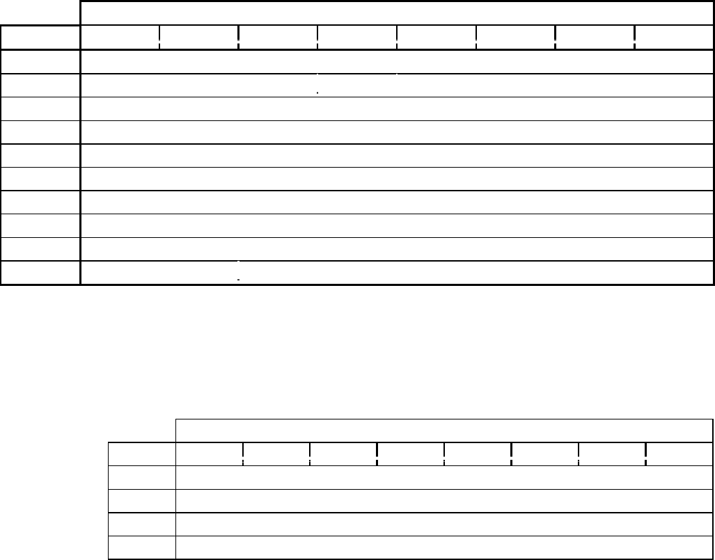
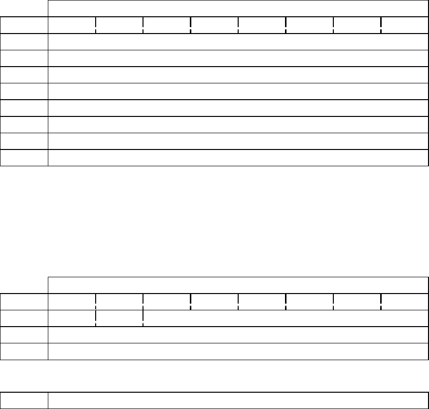
TABLE 1-5 SAMPLE COMMAND
Bit
Byte 76543210
0Operation Code (XXh)
1Logical Number Reserved
2Logical Block Address (MSB)
3Logical Block Address
4Logical Block Address
5Logical Block Address (LSB)
6Reserved
7Allocation Length (MSB)
8Allocation Length (LSB)
9Reserved
Operation Code : XXh
Logical Unit Number specifies which Logical Unit the command applies to.
Logical Block Address specifies which Logical Block Address (LBA) the operation is to start.
Allocation Length is (depending on the command) the number of Logical Blocks or the number
of bytes that the initiator is expecting to receive from the drive.

Preface
- 7 -
Message Out-Phase (issued by host computer)
INITIATED DEFECTED ERROR 05h
ABORT 06h
NO OPERATION 08h
MESSAGE PARITY ERROR 09h
BUS DEVICE DRIVER30Ch
TERMINATE IO PROCESS 11h
IDENTIFY 80h - FFh
SYNCHRONOUS DATA TRANSFER REQUEST401h
1.4 Address Format for Answering Occasion (MSF bit)
With some commands, it is possible to choose either Logical Block Address or MSF Format
with Address Field of answering data.
MSF bit
if “0” (FALSE), use Logical Block Address as CD-ROM Absolute Address or Track
Relative Address. If Track Relative Address, the MSF bit is indicated by 2s sequences.
if “1” (TRUE), MSF Format is used. Within the shift area, number declines by a positive
number.
1.5 Sample Command
The table on the opposite page outlines the command structure. Some commands apply to the
entire drive. For these commands only, the LUN will be ignored.
Commands with Logical Blocks, e.g. READ, VERIFY, have Allocation Length in Blocks. All
others have Allocation Length in bytes. Some commands use Transfer Length instead of
Allocation Length to specify the number of bytes that the initiator will transfer to the drive.
3 For equipment supporting Change Definition Command, the DRM/DR-U Series drives have a Hardware Reset Option. In this case, the
Change Definition chosen by the SCSI action definition would not be changed or initialized by either the SCSI BUS RESET or BUS
DEVICE RESET message.
4 From EXTEND MESSAGE (01h).
CD-ROM SCSI-2 COMMAND REFERENCE MANUAL VERSION 3.1 (OB-U0077C)
- 8 -
The drive terminates the DATA IN phase when the specified number of bytes have been
transferred or, in the case when the bytes exceed the number of bytes the drive wishes to transfer,
the DATA IN phase is terminated when the number of bytes prepared have been transferred.

Table 2-0 SCSI-2 COMMAND LIST (by Name)
Applied Model Sense Data
Command Name Code I II III Contents of Information Bytes
Audio Scan (1) BAh --- --- 7Logical Block Address
Audio Scan (2) CDh yes yes 7Logical Block Address
Change Definition 40h 1 --- ---
Inquiry 12h yes yes yes
Mode Select(6) 15h 2 2 yes
Mode Select(10) 55h 2 2 yes
Mode Sense(6) 1Ah 2 2 yes
Mode Sense(10) 5Ah 2 2 yes
Pause/Resume 4Bh yes yes yes Logical Block Address
Play Audio (10) 45h yes yes yes Logical Block Address
Play Audio (12) A5h yes yes yes Logical Block Address
Play Audio MSF 47h yes yes yes Logical Block Address
Play Audio Track/Index 48h yes yes yes Logical Block Address
Play Track Relative (10) 49h yes yes yes Logical Block Address
Play Track Relative (12) A9h yes yes yes Logical Block Address
Prevent/Allow Medium Removal 1Eh yes yes yes
Read (6) 08h yes yes yes Logical Block Address
Read (10) 28h yes yes yes Logical Block Address
Read (12) A8h yes yes yes Logical Block Address
Read Buffer 3Ch yes yes yes
Read CD BEh --- --- 3Logical Block Address
Read CD-DD D8h --- yes 3Logical Block Address
Read CD MSF B9h --- --- 3Logical Block Address
Read CD-DA MSF D9h --- yes 3Logical Block Address
Read CD-XA DBh --- yes yes Logical Block Address
Read All Subcode DFh --- yes 7Logical Block Address
Read CD-ROM Capacity 25h yes yes yes Logical Block Address
Read Header 44h yes yes yes Logical Block Address
Read Sub-Channel 42h yes yes yes
Read TOC 43h 4 yes yes
Receive Diagnostic Results 1Ch yes yes yes
Release 17h yes yes 5
Request Sense 03h yes yes yes
Reserve 16h yes yes 5
Rezero Unit 01h yes yes yes
Seek (6) 0Bh yes yes yes Logical Block Address
Seek (10) 2Bh yes yes yes Logical Block Address
Send Diagnostic 1Dh yes yes yes
Set CD-ROM Speed (1) BBh --- --- yes
Set CD-ROM Speed (2) DAh yes yes yes
Start/Stop Unit 1Bh yes yes yes
Stop Play/Scan 4Eh --- --- yes
Test Unit Ready 00h yes yes yes
Verify (10) 2Fh yes yes --- Logical Block Address
Verify (12) AFh yes yes --- Logical Block Address
Write Buffer 3Bh yes yes 5
Read CDP E4h yes yes yes
Read Drive Status E0h yes yes yes
Write CDP E3h yes yes yes
Commands
- 9 -
2. COMMANDS
The table on the opposite page lists the commands in the SCSI-2 command set and their corresponding
code, applied model and sense data when applicable.
Applied Model
Applied Model has three values. Each model code corresponds to particular drive models.
I : product models DRM-604X; DRM-1804X; and DR-D504X
II : product model DRM-602X
III : product models DRM-624X; DR-U124X; DR-UA124X; DR-A10X; DR-U10X;
DR-A12X; DR-411; DR-U12X; DR-433; DR-A24X; DR-511; DR-U24X; and
DR-533
Each command is either supported by a drive, indicated by “yes”, not supported by a drive, “---“,
or is supported but with restrictions and/or conditions, “N” where N is a numeric value 1-7.
yes : is supported by all drives corresponding to this Applied Model code.
--- : is not supported by any of the drives corresponding to this Applied Model code.
1 : is not supported by DRM-1804X.
2 : does not support the media type code 4h, 8h, 70h, 71h and 72h. There is limited
action in the CD-ROM Audio Controller Parameter Page (0Eh).
3 : random access is possible with CD-DA data. Buffer Over Flow Error would not
occur. For SUB-CHANNEL READ OUT, support is only when the Beginning
Logical Block Address is FFFFFFFFh and Sub-Channel data. It is unable to
choose the Beginning Logical Block Address or to read out along with other
data.
4 : is not supported by Format Field = 2 (all of Q Sub-Code information).
5 : is not supported by DR-UA124X.
6 : is unable to reassign disc of single type drive.
7 : is not supported by DR-A10X, DR-U10X, DR-411, DR-433, DR-A12X, DR-
U12X, DR-444, DR-466, DR-A24X, DR-U24X, DR-511 and DR-533.
Upon execution of some commands, a Page Code is returned. The table on the next page lists the various
CD-ROM Mode Page Codes.
NOTE: The Applied Model values and the support codes listed above apply to the CD-ROM Mode Page
Code List on the next page. (The values are listed opposite the table for your convenience.)

CD-ROM SCSI-2 COMMAND REFERENCE MANUAL VERSION 3.1 (OB-U0077C)
- 10 -
TABLE 2-0A CD-ROM MODE PAGE CODE LIST
Applied Model
Page Code Description Section I II III
00h Only Block Descriptor yes yes yes
01h Read Error Recovery Page 2.9.1 yes yes yes
07h Verify Error Recover page 2.9.2 yes yes ---
0Bh Peripheral Device page 2.9.3 yes yes yes
0Dh CD-ROM Parameters page 2.9.5 yes yes yes
0Eh CD-ROM Audio Control page 2.9.6 yes yes yes
2Ah CD-ROM Capabilities & Mechanical Status page 2.9.7 --- --- yes
31h Drive Speed page 2.9.8 yes yes yes
3Eh Logical Unit Assignment page 2.9.9 666
3Fh Return all pages5yes yes yes
5 Valid only for the MODE SENSE command.
Commands
- 11 -
Applied Model
Applied Model has three values. Each model code corresponds to particular drive models.
I : product models DRM-604X; DRM-1804X; and DR-D504X
II : product model DRM-602X
III : product models DRM-624X; DR-U124X; DR-UA124X; DR-A10X; DR-U10X;
DR-A12X; DR-411; DR-U12X; DR-433; DR-A24X; DR-511; DR-U24X; and
DR-533
Each command is either supported by a drive, indicated by “yes”, not supported by a drive, “---“,
or is supported but with restrictions and/or conditions, “N” where N is a numeric value 1-7.
yes : is supported by all drives corresponding to this Applied Model code.
--- : is not supported by any of the drives corresponding to this Applied Model code.
1 : is not supported by DRM-1804X.
2 : does not support the media type code 4h, 8h, 70h, 71h and 72h. There is limited
action in the CD-ROM Audio Controller Parameter Page (0Eh).
3 : random access is possible with CD-DA data. Buffer Over Flow Error would not
occur. For SUB-CHANNEL READ OUT, support is only when the Beginning
Logical Block Address is FFFFFFFFh and Sub-Channel data. It is unable to
choose the Beginning Logical Block Address or to read out along with other
data.
4 : is not supported by Format Field = 2 (all of Q Sub-Code information).
5 : is not supported by DR-UA124X.
6 : is unable to reassign disc of single type drive.
7 : is not supported by DR-A10X, DR-U10X, DR-411, DR-433, DR-A12X, DR-
U12X, DR-444, DR-466, DR-A24X, DR-U24X, DR-511 and DR-533.
CD-ROM SCSI-2 COMMAND REFERENCE MANUAL VERSION 3.1 (OB-U0077C)
- 12 -
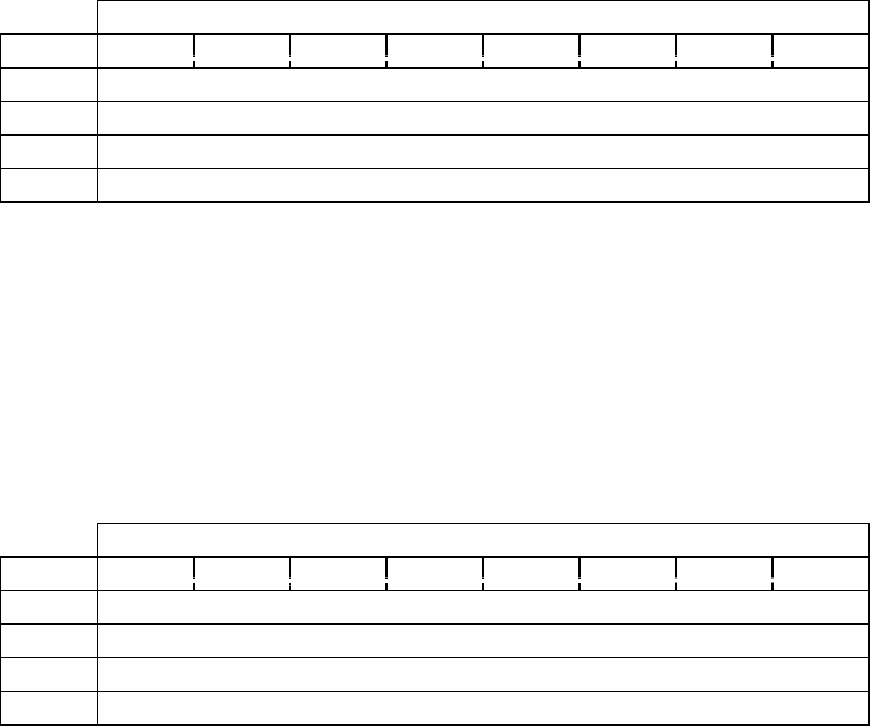
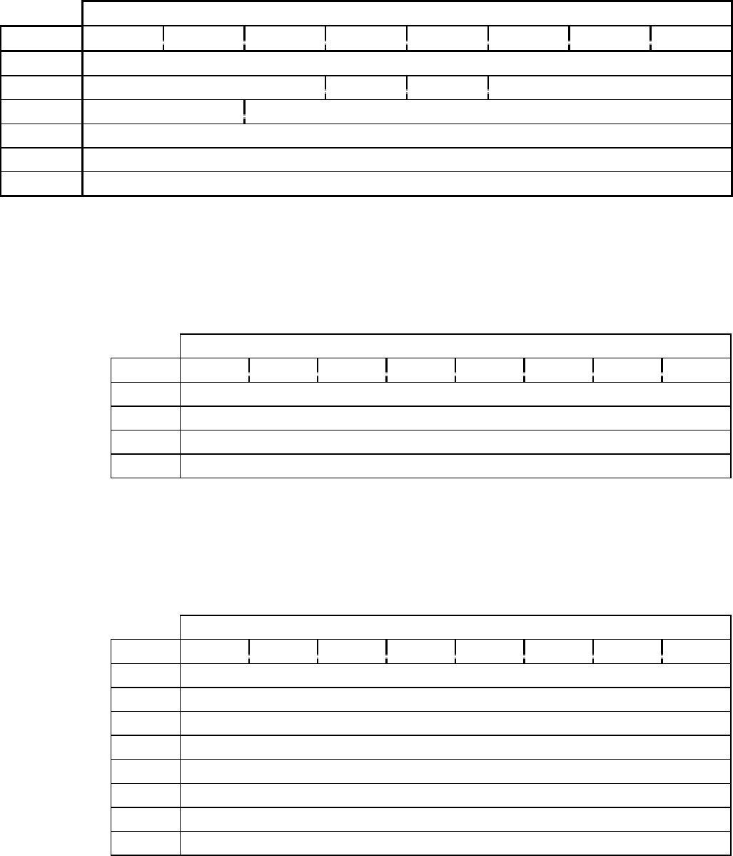
TABLE 2-1 AUDIO SCAN (1)
Bit
Byte 76543210
0Operation Code (CDh)
1Logical Unit Number Direct Reserved
2Scan Start Address (MSB)
3Scan Start Address
4Scan Start Address
5Scan Start Address (LSB)
6Reserved
7Reserved
8Reserved
9Type Reserved
TABLE 2-1A LOGICAL BLOCK ADDRESS FORMAT (TYPE = 00B)
Bit
Byte 76543210
2Logical Block Address (MSB)
3Logical Block Address
4Logical Block Address
5Logical Block Address (LSB)
Audio Scan (1)
- 13 -
2.1 Audio Scan (1) (CDh)
When AUDIO SCAN (1) is executed, the drive begins a high-speed scan from the Scan Start
Address. The drive plays a block as it crosses each track. Each scan is approximately 15 seconds.
When the specified search address is found, GOOD status is returned.
If the drive is not ready or if the Scan Start Address is not on an audio track, Check Condition
status is returned.
During an audio scan, the drive can receive and execute the following SCSI commands without
scan termination:
AUDIO PLAY (StpAdr=1), AUDIO STATUS, AUDIO STOP
INQUIRY
MODE SELECT, MODE SENSE
READ BUFFER, WRITE BUFFER
READ CD-ROM CAPACITY, READ SUB CHANNEL, READ TOC
RECEIVE DIAGNOSTIC RESULTS, REQUEST SENSE, TEST UNIT READY
RELEASE, RESERVE
There are several commands that when received by the drive during an audio scan, the drive will
terminate the scan and execute the received command. The commands are:
PLAY AUDIO (StpAdr=0), AUDIO SCAN, PLAY AUDIO TRACK
PAUSE/RESUME
READ, SEEK, VERIFY
READ HEADER
START/STOP UNIT, REZERO UNIT
SEND DIAGNSTICS
PREVENT/ALLOW MEDIA REMOVAL
Operation Code is (CDh).
Direct
is “0” (FALSE) when the drive scans forward.
is “1” (TRUE) when the drive scans backwards.
Scan Start Address contains the address at which the audio scan is to begin.
CD-ROM SCSI-2 COMMAND REFERENCE MANUAL VERSION 3.1 (OB-U0077C)
- 14 -
TABLE 2-1B AMIN, ASEC AND AFRAME ADDRESS FORMAT (TYPE = 01B)
Bit
Byte 76543210
2Reserved
3CD absolute time (AMIN)
4CD absolute time (ASEC)
5CD absolute time (AFRAME)
AMIN, ASEC and AFRAME show the absolute time for the beginning of the disc in BCD. The
values must be in the ranges 0~99 (AMIN), 0~59 (ASEC) and 0~74 (AFRAME).
TABLE 2-1C TRACK NUMBER ADDRESS FORMAT (TYPE = 10B)
Bit
Byte 76543210
2Reserved
3Reserved
4Reserved
5Track number (TNO) (01-99)
Audio Scan (1)
- 15 -
Type defines the format of the Scan Start address field. Type has four parameters.
The four (4) parameters are
00b :Logical Block Address format (reference Table 2-1A)
01b :AMIN, ASEC and AFRAME format (reference Table 2-1B)
10b :Track Number Address format (reference Table 2-1C)
11b :Reserved

CD-ROM SCSI-2 COMMAND REFERENCE MANUAL VERSION 3.1 (OB-U0077C)
- 16 -
TABLE 2-2 AUDIO SCAN (2)
Bit
Byte 76543210
0Operation Code (BAh)
1Reserved Direct Reserved
2Scan Starting Address (MSB)
3Scan Starting Address
4Scan Starting Address
5Scan Starting Address (LSB)
6Reserved
7Reserved
8Reserved
9Type Reserved
10 Reserved
11 Reserved
Audio Scan (2)
- 17 -
2.2Audio Scan (2) (BAh)
Operation Code is (BAh).
Direct
If “0” (FALSE), the drive scans forward.
If “1” (TRUE), the drive scans backwards.
Scan Start Address is the address at which the audio scan begins operation.
Type defines the format of the Scan Start address field. Type has four parameters.
The four (4) parameters are
00b :Logical Block Address format (reference Table 2-1A)
01b :AMIN, ASEC and AFRAME format (reference Table 2-1B)
10b :Track Number Address format (reference Table 2-1C)
11b :Reserved

CD-ROM SCSI-2 COMMAND REFERENCE MANUAL VERSION 3.1 (OB-U0077C)
- 18 -
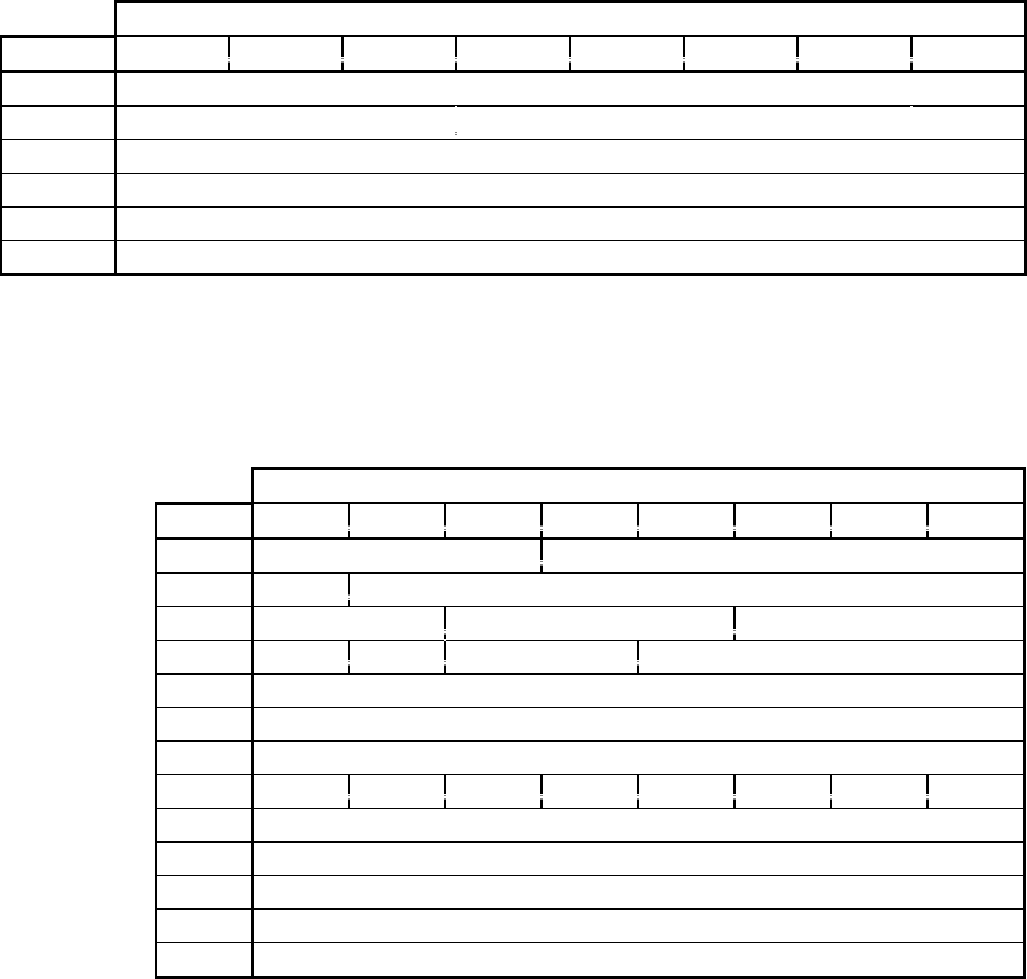
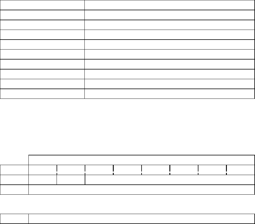
TABLE 2-3 CHANGE DEFINITION
Bit
Byte 76543210
0Operation Code (40h)
1Logical Unit Number Reserved
2Reserved SCB=0
3Reserved Definition Parameter
4Reserved
5Reserved
6Reserved
7Reserved
8Parameter Data Length (0)
9Reserved
Change Definition
- 19 -
2.3 Change Definition (40h)
When executed, the CHANGE DEFINITION command modifies the operating definition of the
drive regardless of the specified logical unit number.
A SCSI reset or BUS DEVICE RESET will not affect the definition changed by the CHANGE
DEFINITION command.
Cycling the power to the drive OFF and ON will cause the operating definition to revert to the
default setting.
If the CHANGE DEFINITION command did not execute successfully, the operating definition
will remain in the same status it was prior to the attempted execution of the CHANGE
DEFINITION command.
Operation Code is (40h).
Save Control Bit (SCB)
Must be set to “0” (FALSE).
The drive will not save the operating definition. A power reset will set the drive to its initial
operating definition.
Definition Parameter specifies the operating definition. The Definition Parameter field supports
the following field values:
00h :Use current operating definition
01h :SCSI-1 operating definition
02h :SCSI-1 operating definition
03h :SCSI-2 operating definition
04h~7Fh :Reserved
DRIVE NOTES:
This command is used by the DRM-604X.
Drives that are SCSI-2 only and will reject the CHANGE DEFINITION command are:
DRM-602X, DRM-624X, DRM-1804X and the DR-U Series drives
CD-ROM SCSI-2 COMMAND REFERENCE MANUAL VERSION 3.1 (OB-U0077C)
- 20 -
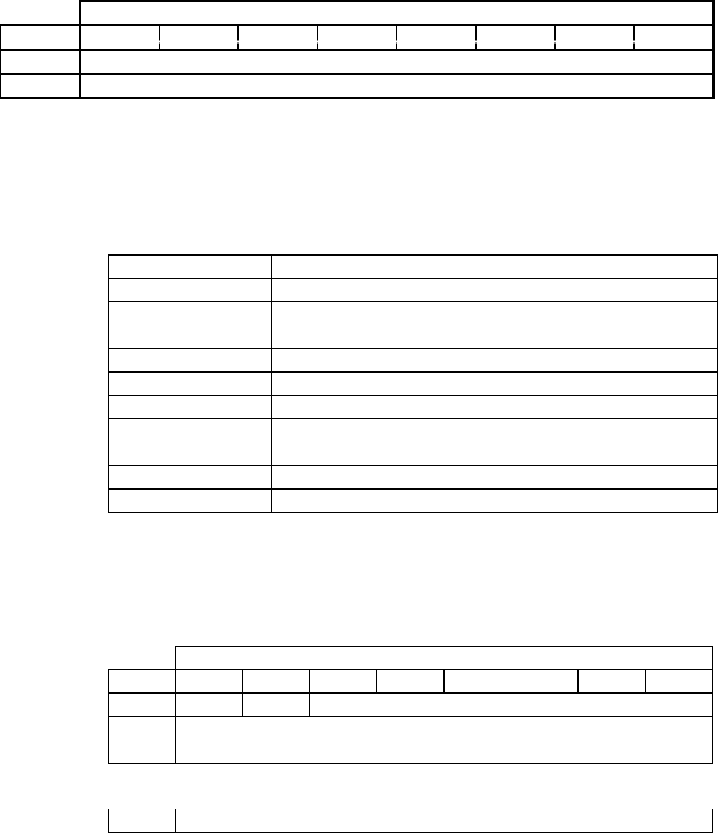
TABLE 2-4 INQUIRY
Bit
Byte 76543210
0Operation Code (12h)
1Logical Unit Number Reserved EVPD (0)
2Reserved
3Reserved
4Allocation Length : 47 (2Fh)
5Reserved
TABLE 2-4A INQUIRY DATA FORMAT
Bit
Byte 76543210
0Peripheral Qualifier Peripheral Device Type (05h)
1RMB Reserve
2 0 0 ANSI Version (2)
3 0 TIOP Reserve Response Format (2)
4Additional Length : 42 (2Ah)
5Reserve
6Reserve
7000SYNC 0Reserve 0 0
8~15 Vendor Name (8-byte ASCII code) (PIONEER)
16~31 Product Inquiry Data (16-byte ASCII code)
32~35 Revision Number (ASCII code) (“XXXX”)
36 Release Version (20h)
37~46 Revision Date (10-byte ASCII code) (“YYYY/MM/DD”)
Inquiry
- 21 -
2.4 Inquiry (12h)
The INQUIRY command supports standard 47 Bytes Inquiry data. If byte length in Allocation
Length is less than 47 bytes, the requested length is transferred. If byte length is 47 bytes or
more, only 47 bytes will be transferred.
The INQUIRY command returns Check Condition if data transfer to the Initiator was not
properly received.
Whenever a Check Condition is returned against any command, inquiry data is returned
providing the initiator with system information.
Operation Code is (12h).
Enable Vital Product Data (EVPD)
Must be set to “0” (ZERO) for the drive to return the standard Inquiry data.
If the Page Code field is not set to “0” (ZERO), the drive will return Check Condition
Status (Sense Key: Illegal Request) and sense code INVALID FIELD IN CDB.
Table 2-4A on the opposite page illustrates the standard Inquiry data format.
RMB
If “1” (TRUE), the media is removable.
TIOP
If “1” (TRUE), the drive will support the Terminate I/O Process message.
SYNC
If “1” (TRUE), the drive supports synchronous data transfers.
Table 2-4B on the next page outlines the drive specific values for bytes 16~31, Product Inquiry
Data; and bytes 32~35, Revision Number.

CD-ROM SCSI-2 COMMAND REFERENCE MANUAL VERSION 3.1 (OB-U0077C)
- 22 -
TABLE 2-4B DRIVE SPECIFIC STRINGS
Bytes
Drives 16 ~ 31 (Product Data) 32 ~ 35 (Revision Number)
DRM-602X CD-ROM DRM-602X 29XX6
DRM-604X CD-ROM DRM-604X 24XX
DRM-624X CD-ROM DRM-624X 01XX
DRM-1804X CD-ROM DRM-1804X 01XX
DR-D504X CD-ROM DR-D504X 24XX
DR-A10X CD-ROM DR-A10X 01XX
DR-U10X CD-ROM DR-U10X 01XX
DR-411 CD-ROM DR-A10X 01XX
DR-433 CD-ROM DR-U10X 01XX
DR-A12X CD-ROM DR-A12X 01XX
DR-U12X CD-ROM DR-U12X 01XX
DR-444 CD-ROM DR-A12X 01XX
DR-466 CD-ROM DR-U12X 01XX
DR-A24X CD-ROM DR-A24X 01XX
DR-U24X CD-ROM DR-U24X 01XX
DR-511 CD-ROM DR-A24X 01XX
DR-533 CD-ROM DR-U24X 01XX
6 Where X denotes a whole number, 0-9.
Inquiry
- 23 -
(this page has been left intentionally blank)
CD-ROM SCSI-2 COMMAND REFERENCE MANUAL VERSION 3.1 (OB-U0077C)
- 24 -
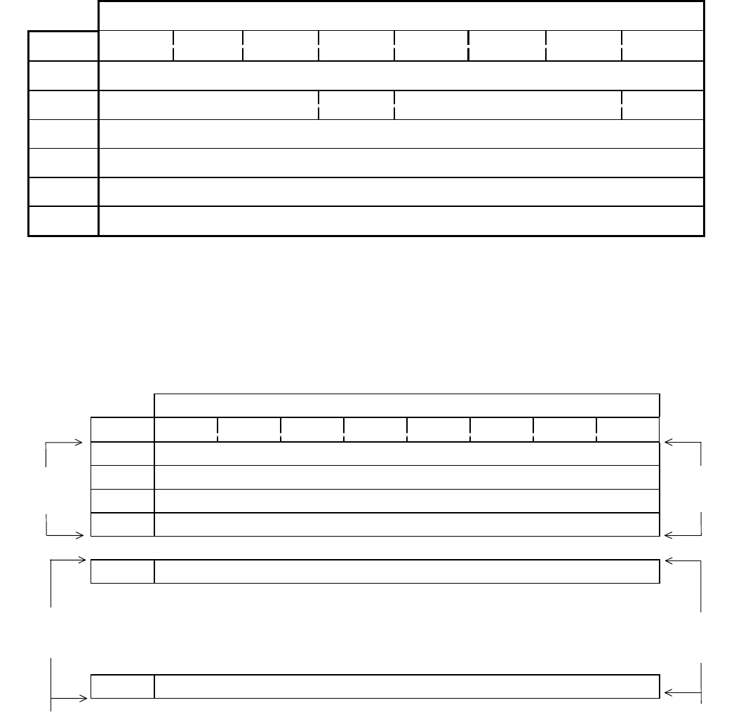
TABLE 2-5 MODE SELECT(6) (15H)
Bit
Byte 7 6 5 4 3 2 1 0
0Operation Code (15h)
1Logical Unit Number PF Reserved SP
2Reserved
3Reserved
4Parameter List Length
5Reserved
TABLE 2-5A MODE SELECT(6) HEADER AND PARAMETER LIST
Bit
Byte 7 6 5 4 3 2 1 0
0Reserved
1Media Type (0)
2Reserved
3Block Descriptor Length (0 or 8)
4Block Descriptor / Page Descriptor(s)
:
:
:
NBlock Length (LSB) / Ending Element Address (LSB)
Block
Header
Block
Header
Block Descriptor
and/or
Page Code
Block Descriptor
and/or
Page Code
Mode Select(6)
- 25 -
2.5 Mode Select(6) (15h)
The MODE SELECT(6) command provides a range for the initiator specifying specific operating
parameters, e.g., medium, logical unit and peripheral device parameters.
IMPORTANT: Initiators should issue the MODE SENSE command (reference Section 2.7)
prior to each execution of the MODE SELECT command to determine supported pages, page
lengths and other parameters.
Operating Code is (15h).
PF (Page Format)
Must be set to “1” (TRUE). The drive does not check the value of the Page Format bit.
SP (Save Parameters)
Must be set to “0” (FALSE). Parameter saving is not supported.
Parameter List Length
If “0” (ZERO), no data will be transferred.
The Parameter List Length is the number of bytes of the Mode Select Parameter List that is
to be transferred in the Data Out phase. A parameter list length that results in the truncation
of any descriptor, header or page parameters will cause the target to terminate the
command. In this case Check Condition Status (Sense Key : Illegal Request) is returned
and Sense Code is set to Parameter List Length Error.
Using the MODE SELECT command, the initiator can assign or alter parameters for the logical
units. The Parameter List includes a 4-byte header, followed by 0-1 block descriptors and 0-N,
where N is a whole number, page descriptions. Refer to Table 2-5A on the opposite page. The
drive keeps parameters, the block descriptor and parts of page descriptors for each logical unit in
its controller memory. When the drive is reset, the default parameter values are restored.
Refer to Table 2-5B on the next page for details on the Block Descriptor format.
Refer to Table 2-5C on the next page for details on the Page Descriptor format.
After the MODE SELECT command is received, the drive returns Check Condition Status
(Sense Key : Unit Attention) and sets sense key to Mode Select Parameter Changed for the first
command received (except for INQUIRY or REQUEST SENSE) from any other initiator. The
Sense Key Unit Attention is returned even if the parameters have not actually changed with the
MODE SELECT command.
CD-ROM SCSI-2 COMMAND REFERENCE MANUAL VERSION 3.1 (OB-U0077C)
- 26 -
TABLE 2-5B BLOCK DESCRIPTOR
Bit
Byte 76543210
0Density Code
1Number of Blocks (MSB)
2Number of Blocks
3Number of Blocks (LSB)
4Reserved
5Block Length (MSB)
6Block Length
7Block Length (LSB)
TABLE 2-5C PAGE DESCRIPTOR
Bit
Byte 76543210
0Reserve Reserve Page Code
1Page Length
2Mode Parameter Page Definition
:
:
NMode Parameter Page Definition
Mode Select(6)
- 27 -
BLOCK DESCRIPTOR
Media Type
Set to “0” (ZERO).
Block Descriptor Length
If “0” (ZERO), there is no block description included in the parameter list.
Set to “0” or “8”.
Density Code specifies data type to be transferred. Five (5) parameters are supported. They are
01h :User data only (2048 bytes/physical sector) [default]
02h :User data plus auxiliary data (2336 bytes/physical sector)
03h :Header, user data plus auxiliary data (2340 bytes/physical sector)
04h :Audio data only (1/75th of a second per logical block)
05h~FFh :Reserved
Number of Blocks
Set to “0” (ZERO).
Logical Block Length specifies logical block size in number of bytes. In the current version,
256, 512, 1024, 2048(default), 2052, 2056, 2336, 2340 and 2352 byte are supported. An external
switch on the back of the DRM-602X, DRM-604X and DRM-1804X drives allows the power-on
default value to be switched to either 512 or 2048.
PAGE DESCRIPTOR
Page Code indicates the meaning of the data contained in the page.
Page Length is the number of bytes supported for each page. It does not include the page length
byte.
The drive will return Check Condition if ECC is enabled and the initiator accesses a Mode 1 or
Mode 2 form1 data block and has specified 2336-, 2340-, or 2352 byte length.
When the initiator accesses a Mode 2 form2 data block and has specified 2336-, 2340- or 2352-
byte lengths, the ECC must be disabled. The drive will return Check Condition.
The first two bytes of the page descriptor comprise the header which consists of the Page Code
and Page Length. Following the header are the page definitions.

CD-ROM SCSI-2 COMMAND REFERENCE MANUAL VERSION 3.1 (OB-U0077C)
- 28 -
TABLE 2-6 MODE SELECT(10) (55H)
Bit
Byte 76543210
0Operation Code (55h)
1Logical Unit Number PF Reserved SP
2Reserved
3Reserved
4Reserved
5Reserved
6Reserved
7Parameter List Length (MSB)
8Parameter List Length (LSB)
9Reserved
Mode Select(10)
- 29 -
2.6 Mode Select(10) (55h)
The MODE SELECT(10) command provides a range for the initiator specifying specific
operating parameters. Refer to MODE SELECT(6) Command, Section 2.5 for details of the
command fields.
IMPORTANT: Initiators should issue the MODE SENSE command (reference Sections 2.7
and 2.8) prior to each execution of the MODE SELECT command to determine supported pages,
page lengths and other parameters.
CD-ROM SCSI-2 COMMAND REFERENCE MANUAL VERSION 3.1 (OB-U0077C)
- 30 -
TABLE 2-7 MODE SENSE(6) (1AH)
Bit
Byte 765 4321
0Operation Code (1Ah)
1Logical Unit Number Reserved DVD Reserved
2PCF Page Code
3Reserved
4Allocation Length
5Reserved
TABLE 2-7A MODE SENSE DATA HEADER
Bit
Byte 76543210
0Reserved
1Media Type
2Reserved
3Block Descriptor Length (0 or 8)
TABLE 2-7B BLOCK DESCRIPTOR
Bit
Byte 76543210
0Density Code
1Number of Blocks (MSB)
2Number of Blocks
3Number of Blocks (LSB)
4Reserved
5Block Length (MSB)
6Block Length
7Block Length (LSB)
Mode Sense(6)
- 31 -
2.7 Mode Sense(6) (1Ah)
Operation Code is (1Ah)
DBD (Disable Block Descriptor)
If “0” (ZERO), the block descriptors are returned in the MODE SENSE data.
If “1” (TRUE), no block descriptors are returned.
PCF (Page Control Field) specifies the Page Parameter Type to be returned.
Page Code specifies the Page(s) to be returned.
The MODE SENSE command requests the drive to report parameters for each logical unit. An
Allocation Length of “0” means that no data is returned. If other than “0”, the drive terminates
the DATA IN phase when Allocation Length bytes or all the Sense data have been transferred.
The following PCF codes are supported:
00b :Current value: The drive returns the values specified by the latest MODE
SELECT command. If no MODE SELECT command has
been issued, the default values are returned.
01b :Alterable value: The drive returns the alterable parameters set to one in the
requested page. Even if all parameter values are unalterable,
the requested page(s) is returned.
10b :Default value: The default values of the drive are returned. The fields and
bits that are not supported are set to 0.
11b :Reserved
Mode Sense Data Format
The Mode Sense Data consists of a 4-byte header; an 8-byte block descriptor; and no, one,
or more page descriptor(s).
Sense Data Length
Shows the length in bytes of the following Sense data. This length does not include itself
(byte 0).
Media Type
The default value is 0.
Block Descriptor Length
The value 8 is always returned.
CD-ROM SCSI-2 COMMAND REFERENCE MANUAL VERSION 3.1 (OB-U0077C)
- 32 -
TABLE 2-7C MEDIA TYPE CODE
Media Type Code Type of Media
00h Default
01h 120mm CD-ROM Data
02h 120mm CD-DA Audio
03h 120mm CD-ROM Data/Audio
04h Reserved
05h 80mm CD-ROM Data
06h 80mm CD-ROM Audio
07h 80mm CD-ROM Data/Audio
08h ~ FFh Reserved
TABLE 2-7D PAGE DESCRIPTOR FORMAT
Bit
Byte 76543210
0Reserve Reserve Page Code
1Page Length
:
:
NPage Definition
Mode Sense(6)
- 33 -
Number of blocks
The value 0 means that the length of all blocks is same as the Logical Block Length shown
in the block descriptor.
Logical Block Length
Indicates the logical block size in bytes. In the current version, 256, 512, 1024,
2048(default), 2052, 2336, 2340 and 2352 byte are supported. The default values for the
CD-ROM drives (512 or 2048) are selectable with an external switch.
Density Code
01h :User data only (2048 bytes/physical sector)(default)
02h :User data plus auxiliary data (2336 bytes/physical sector)
03h :Header, user data plus auxiliary data (2340 bytes/physical sector)
04h :Audio data only (1/75th of a second per logical block)
05h~FFh :Reserved
The drive will return Allocation Length bytes or the complete sense data.
Each page descriptor starts with a 2-byte header consisting of the page code and page length, and
the specified page data follow the header.
Page code indicates the meaning of the data contained in the page.
Page length does not include the page length byte itself. The page length indicates the number of
bytes supported for each page.

CD-ROM SCSI-2 COMMAND REFERENCE MANUAL VERSION 3.1 (OB-U0077C)
- 34 -
TABLE 2-8 MODE SENSE(10) (5AH)
Bit
Byte 76543210
0Operation Code (5Ah)
1Logical Unit Number Reserved DVD Reserved
2PCF Page Code
3Reserved
4Reserved
5Reserved
6Reserved
7Allocation Length (MSB)
8Allocation Length (LSB)
9Reserved
Mode Sense(10)
- 35 -
2.8 Mode Sense(10) (5Ah)
Operation Code is (5Ah)
The MODE SENSE(10) command provides a means for a target to report parameters to the
initiator. It is the complementary command to the MODE SELECT(10) command. See MODE
SENSE(6) command (reference Section 2.7) for a complete description of the fields in this
command.
CD-ROM SCSI-2 COMMAND REFERENCE MANUAL VERSION 3.1 (OB-U0077C)
- 36 -
TABLE 2-9 MODE SELECT/SENSE PARAMETERS
Bit
Byte 76543210
0 ~ N Mode Parameter Header
0 ~ N Page(s)
TABLE 2-9A MODE PAGE CODES FOR CD-ROM
Page Code Description
00h Only Block Descriptor
01h Read Error Recover Page
07h Verify Error Recovery Page
0Bh Peripheral Device Page
0Dh CD-ROM Parameters Page
0Eh CD-ROM Audio Control Page
2Ah CD-ROM Capabilities & Mechanical Status Page
31h Drive Speed Page
3Eh Logical Unit Assignment Page
3Fh Return all pages (valid only for the MODE SENSE command)
TABLE 2-9B MODE PAGE FORMAT
Bit
Byte 76543210
0PS/Resr Reserve Page Code
1Page Length (N-1)
2Mode Parameters
:
:
NMode Parameters
Mode Select/Sense Parameters
- 37 -
2.9 Mode Select/Sense Parameters
This section describes the pages used with MODE SELECT and MODE SENSE commands.
The Mode Parameter List contains a header, followed by zero or more variable -length pages.
Each mode page contains a page code, a page length , and a set of mode parameters.

CD-ROM SCSI-2 COMMAND REFERENCE MANUAL VERSION 3.1 (OB-U0077C)
- 38 -
TABLE 2-9-1 PAGE CODE 01H - ERROR RECOVERY PARAMETERS
Bit
Byte 76543210
0Reserve Reserve Page Code (01h)
1Page Length (06h)
2Reserve Reserve TB RC EEC PER DTE CDR
3Retry Number
4Reserve
5Reserve
6Reserve
7Reserve
TABLE 2-9-1A VALID COMBINATIONS OF THE ERROR RECOVERY PARAMETERS
Code Reserve TB RC EEC PER DTE DCR
00h 0 0 00 0 0 0 0 0
01h 0 0 0 0 0 0 0 1
04h 0 0 0 0 0 1 0 0
05h 0 0 0 0 0 1 0 1
06h 0 0 0 0 0 1 1 0
07h 0 0 0 0 0 1 1 1
10h 0 0 0 1 0 0 0 0
11h 0 0 0 1 0 0 0 1
14h 0 0 0 1 0 1 0 0
15h 0 0 0 1 0 1 0 1
20h 0 0 1 0 0 0 0 0
21h 0 0 1 0 0 0 0 1
24h 0 0 1 0 0 1 0 0
25h 0 0 1 0 0 1 0 1
26h 0 0 1 0 0 1 1 0
27h 0 0 1 0 0 1 1 1
Error Recovery Parameters
- 39 -
2.9.1 Error Recovery Parameters
NOTE: When the bit definition of this error recovery parameter and the error recovery
procedure (described later) are not in agreement, the error recovery procedure takes
priority.
DCR (Disable Correction)
If “1”, data is transferred without Layered ECC (L-ECC) error correction.
If “0”, L-ECC error correction is performed. The default value is 0.
DTE (Disable Transfer on Error)
If “0”, transfer of recovered data is allowed. The default value is 0.
When both the DTE and PER bit are 1, the target stops the data transfer
immediately if the error is detected, and then returns Check Condition status.
NOTE: The TB bit controls whether data from the bad block is transferred.
PER (Post Error)
If “1”, the drive returns a Check Condition status for a recovered error.
If “0”, no Check Condition status is returned for the recovered error.
The default value is 0.
EEC (Enable Early Correction)
This bit must be 0: The defined retry procedure is performed prior to the error
correction.
RC (Read Continuous)
Set to 0. A delay in the data transfer may occur due to an error recovery action.
TB (Transfer Block)
If “1”, uncorrected data blocks will be transferred to the initiator.
If “0”, uncorrected data blocks are not transferred. The default value is 0.
NOTE: in either case, the block address returned to the REQUEST SENSE command
is not of the preceding good block but of the error block.
Retry Number specifies how many times the drive re-tries a physical read operation
when it finds an uncorrectable block. The default value is 4.

CD-ROM SCSI-2 COMMAND REFERENCE MANUAL VERSION 3.1 (OB-U0077C)
- 40 -
TABLE 2-9-1B ERROR RECOVERY DESCRIPTIONS
Value Description
00h The maximum error recovery procedures available are used. If an error occurs which
is uncorrectable with the error correction codes (ECC) on the media, data transfer is
terminated with Check Condition status. The block with the error is not transferred.
The sense key is set to Medium Error. The information bytes give the address of the
block where the unrecovered error was detected. Recovered errors are not reported.
01h Only retries of the read operation and CIRC are used (layered error correction is not
used). Only CIRC unrecovered data errors are reported. If a CIRC unrecovered data
error occurs, data transfer is terminated with Check Condition status. The block with
the error is not transferred. The sense key is set to Medium Error. The information
bytes give the address of the block where the unrecovered error was detected.
Recovered errors are not reported.
04h The maximum error recovery procedures available are used. Recovered data errors
are reported. If a recovered data error occurs, data transfer is not terminated.
However, when the data transfer has completed Check Condition status is reported.
The sense key is set to Recovered Error. The information bytes give the address of
the last block where a recovered data error was detected. If a data error occurs which
is uncorrectable with the ECC information available on the media, data transfer is
terminated and Check Condition status is reported. The block with the error is not
transferred. The sense key is set to Medium Error. The information bytes give the
address of the block where the uncorrectable error was detected.
05h Only retries of the read operation and CIRC are used (layer error correction is not
used). Recovered data errors are reported. If a recovered data error occurs, data
transfer is not terminated. However, when the data transfer has completed Check
Condition status is reported. The sense key is set to Recovered Error. The information
bytes five the address of the last block where a CIRC recovered data error was
detected. If an unrecovered data error occurs data transfer is terminated and Check
Condition status is reported. The block with the error is not transferred. The sense key
is set to Medium Error. the information bytes give the address of the block where the
unrecovered error was detected.
06h The maximum error recovery procedures are sued. Recovered data errors are
reported. If a recovered data error occurs data transfer is terminated and Check
Condition status is reported. The block with the recovered error is not transferred.
The sense key is set to Recovered Error. the information bytes give the address of the
block where the recovered data was detected. if a data error occurs which is
uncorrectable with the ECC information on the medium, data transfer is terminated
with Check Condition status. The block with the error is not transferred. The sense
key is set to Medium Error. The information bytes give the address of the block
where the uncorrectable error was detected.
07h Only retries of the read operation are used (layer error correction is not used). CIRC
recovered data errors are reported. If a CIRC recovered data error occurs, data
transfer is terminated with Check Condition status. The block with the recovered
error is not transferred. The sense key is set to Recovered Error. The information
bytes five the address of the block where the recovered data error was detected. If a
CIRC unrecovered data error occurs, data transfer is terminated with Check
Condition status. The block with the error is not transferred. The sense key is set to
Medium Error. The information bytes give the address of the block where the
unrecovered error was detected.
continued on next page

Error Recovery Parameters
- 41 -
TABLE 2-9-1B ERROR RECOVERY DESCRIPTIONS (CONTINUED)
Value Description
10h If data transfer can be maintained, the maximum error recovery procedures available
are used. (RC=1) If an error occurs which is uncorrectable with the error correction
codes (ECC) on the media, or is uncorrectable in time to maintain data transfer, the
data transfer is not terminated. However, when the data transfer has completed Check
Condition status is reported. The sense key is set to Medium Error. the information
bytes give the address of the block where the first unrecovered error was detected.
Recovered errors are not reported.
11h If data transfer can be maintained, retries of the read operation and CIRC are used
(layered error correction is not used). (RC=1) Only CIRC unrecovered data errors are
reported. If a CIRC unrecovered data error occurs, data transfer is not terminated.
However, when the data transfer has completed Check Condition status is reported.
The sense key is set to Medium Error. The information bytes give the address of the
block where the first unrecovered error was detected. Recovered errors are not
reported.
14h If data transfer can be maintained, the maximum error recovery procedures available
are used. (RC = 1.) Recovered data errors are reported. If a recovered data error
occurs, data transfer is not terminated. However, when the data transfer has
completed Check Condition status is reported. The sense key is set to Recovered
Error. The information bytes give the address of the block where a recovered data
error was detected. If an data error occurs which is uncorrectable with the ECC
information available on the media, or is uncorrectable in time to maintain data
transfer, the data transfer is not terminated. However, when the data transfer has
completed Check Condition status is reported. The sense key is set to Medium Error.
The information bytes give the address of the block where the first uncorrectable
error was detected. Reporting unrecovered errors takes precedence over reporting
recovered errors.
15h If data transfer can be maintained, retries of the read operation and CIRC are used
(layered error corrections not used). (RC = 1.) Recovered data errors are reported. If
a recovered data error occurs, data transfer is not terminated. However, when the data
transfer has completed Check Condition status is reported. The sense key is set to
Recovered Error. The information bytes give the address of the block where a CIRC
recovered data error was detected. If an unrecovered data error occurs, data transfer is
not terminated. However, when the data transfer has completed Check Condition
status is reported. The sense key is set to Medium Error. The information bytes give
the address of the block where the first unrecovered error was detected. Reporting
unrecovered errors takes precedence over reporting recovered errors.
20h The maximum error recovery procedures available are used. If an error occurs which
is uncorrectable with the error correction codes (ECC) on the media, data transfer is
terminated with Check Condition status. The lock with the error is transferred. The
sense key is set to Medium Error. The information bytes give the address of the block
where the unrecovered error was detected. Recovered errors are not reported.
continued on next page

CD-ROM SCSI-2 COMMAND REFERENCE MANUAL VERSION 3.1 (OB-U0077C)
- 42 -
TABLE 2-9-1B ERROR RECOVERY DESCRIPTIONS (CONTINUED)
Value Description
21h Only retries of the read operation and CIRC are used (layered error correction is not
used). Only CIRC unrecovered data errors are reported. If an CIRC unrecovered data
error occurs data transfer is terminated with Check Condition status. The block with
the error is transferred. The sense key is set to Medium Error. The information bytes
give the address of the block where the unrecovered error was detected. Recovered
errors are not reported.
24h The maximum error recovery procedures available are used. Recovered data errors
are reported. If a recovered data error occurs data transfer is not terminated.
However, when the data transfer has completed Check Condition status is reported.
The sense key is set to Recovered Error. The information bytes give the address of
the last block where a recovered data error was detected. If a data error occurs which
is uncorrectable with the ECC information available on the media data transfer is
terminated and Check Condition status is reported. The block with the error is
transferred. The sense key is set to Medium Error. The information bytes give the
address of the block where the uncorrectable error was detected.
25h Only retries of the read operation and CIRC are used (layered error correction is not
used). Recovered data errors are reported. If a recovered data error occurs, data
transfer is not terminated. However, when the data transfer has completed Check
Condition status is reported. The sense key is set to Recovered Error. The information
bytes give the address of the last block where an CIRC recovered data error was
detected. If an unrecovered data error occurs, data transfer is terminated and Check
Condition status is reported. The block with the error is transferred. The sense key is
set to Medium Error. The information bytes give the address of the block where the
unrecovered error was detected.
26h The maximum error recovery procedures are used. Recovered data errors are
reported. If a recovered data error occurs, data transfer is terminated and Check
Condition status is reported. The block with the recovered error is transferred. The
sense key is set to Recovered Error. The information bytes give the address of the
block where the recovered data error was detected. If a data error occurs which is
uncorrectable with the ECC information on the media, data transfer is terminated
with Check Condition status. The block with the error is transferred. The sense key is
set to Medium Error. The information bytes give the address of the block where the
uncorrectable error was detected.
27h Only retries of the read operation are used (layer error correction is not used). CIRC
recovered data errors are reported. If a CIRC recovered data error occurs, data
transfer is terminated with Check Condition status. The block with the recovered
error is transferred. The sense key is set to Recovered Error. The information bytes
give the address of the block where the recovered data error was detected. If an CIRC
unrecovered data error occurs, data transfer is terminated with Check Condition
status. The block with the error is transferred. The sense key is set to Medium Error.
The information bytes give the address of the block where the unrecovered error was
detected.
Error Recovery Parameters
- 43 -
The CD-ROM errors are:
1) Recovered CIRC (Cross Interleaved Reed-Solomon Code) Error:
An error in a block had been detected by the EDC (Error Detection Code)
but the error was recovered by read retry. Number of read retries to perform
is specified with the Read Retry Number (the third byte of the Error
Recovery Parameter page in the Mode Select command.). In this case, L-
ECC (Layered Error Correction Code) is not used.
2) Uncorrectable CIRC Error:
L-ECC was not used, error could not be corrected by the CIRC after the
specified number of read retries were attempted.
3) Recovered L-ECC Error:
Uncorrectable CIRC Error was found, but the error was corrected by the L-
ECC during read retries.
4) Uncorrectable L-ECC Error:
Error could not be corrected by the L-ECC after the specified number of read
retries were attempted.

CD-ROM SCSI-2 COMMAND REFERENCE MANUAL VERSION 3.1 (OB-U0077C)
- 44 -
TABLE 2-9-2 PAGE CODE 07H - VERIFY ERROR RECOVERY PAGE FORMAT
Bit
Byte 76543210
0PS Reserve Page Code (07h)
1Page Length (06h)
2Error Recovery Parameter
3Verify Retry Count
4Reserved
5Reserved
6Reserved
7Reserved
Verify Error Recovery Page
- 45 -
2.9.2 Verify Error Recovery Page
PS (Parameters Savable)
The Parameters Savable bit is only used with the MODE SENSE command. This
bit is reserved with the MODE SELECT command. A PS bit of one indicates that
the target is capable of saving the page in a non-volatile vendor specific location.
Error Recovery Parameter
The error recovery parameters for verify operations are as defined by the read error
recovery parameters.
The verify error recovery parameters page specifies the error recovery parameter the
target shall use during verify operations.

CD-ROM SCSI-2 COMMAND REFERENCE MANUAL VERSION 3.1 (OB-U0077C)
- 46 -
TABLE 2-9-3 PAGE CODE 09H - PERIPHERAL DEVICE PAGE FORMAT
Bit
Byte 76543210
0Reserved Page Code (09h)
1Page Length (06h)
2Interface Identifier (MSB)
3Interface Identifier (LSB)
4Reserved
5Reserved
6Reserved
7Reserved
TABLE 2-9-3A INTERFACE IDENTIFIER CODES
Value Interface
0000h Small Computer System Interface
0001h Storage Module Interface
0002h Enhanced Small Device Interface
0003h IPI-2
0004h IPI-4
0005h ~ FFFFh Reserved
Peripheral Device Page
- 47 -
2.9.3 Peripheral Device Page
Interface Identifier Codes are in Table 2-9-3A on the opposite page.
The peripheral device page is used to pass vendor-specific information between an
initiator and a peripheral interface below the target.

CD-ROM SCSI-2 COMMAND REFERENCE MANUAL VERSION 3.1 (OB-U0077C)
- 48 -
TABLE 2.9.4 PAGE CODE 0BH - MEDIUM TYPES SUPPORTED PAGE FORMAT
Bit
Byte 76543210
0PS Reserve Page Code (0Bh)
1Page Length (06h)
2Reserved
3Reserved
4Medium Type One Supported
5Medium Type Two Supported
6Medium Type Three Supported
7Medium Type Four Supported
Medium Types Supported Page
- 49 -
2.9.4 Medium Types Supported Page
PS (Parameters Savable)
The Parameters Savable bit is only used with the MODE SENSE command. This bit
is reserved with the MODE SELECT command. A PS bit of one indicates that the
target is capable of saving the page in a non-volatile vendor specific location.
The code values for each medium type supported by the target (up to four maximum),
as defined in the MODE SELECT command are reported in ascending order. If only
the default medium type is supported zero is reported. If less than four medium types
are supported the unused entries shall be returned as zero.

CD-ROM SCSI-2 COMMAND REFERENCE MANUAL VERSION 3.1 (OB-U0077C)
- 50 -
TABLE 2-9-5 PAGE CODE 0DH - CD-ROM PARAMETERS PAGE FORMAT
Bit
Byte 76543210
0Reserve Reserve Page Code (0Dh)
1Parameter Length (06h)
2Reserved
3Reserved Inactivity Timer Multiplier
4
5Number of MSF-S Units per MSF-M Unit (3Ch)
6
7Number of MSF-F Units per MSF-S Unit (4Bh)
TABLE 2-9-5A INACTIVITY TIMER MULTIPLIER VALUE
Inactivity Timer
Multiplier
Time in Hold Track
State
Inactivity Multiplier Time in Hold Track
State
0h Reserved 8h 16 sec
1h 125 ms 9h 32 sec
2h 250 ms Ah 1 min
3h 500 ms Bh 2 min
4h 1 sec Ch 4 min
5h 2 sec Dh 8 min
6h 4 sec Eh 16 min
7h 8 sec Fh 32 min
CD-ROM Parameters Page
- 51 -
2.9.5 CD-ROM Parameters Page
Inactivity Timer Multiplier
The inactivity timer multiplier specifies the length of time that the drive will remain
in the hold track state after completion of a SEEK or READ operation. The default
value is 0Dh. (i.e. 8 minutes). Table 2-6-14 gives a complete listing of the Inactivity
Timer Multiplier.
Number of S per M units
The number of S units per M unit field gives the ratio of these MSF address values.
For media conforming to the CD-ROM and CD-DA standard, this value is 60
(3Ch).
Number of F per S units
The number of F units per S unit field gives the ratio of these MSF address values.
For media conforming to the CD-ROM and CD-DA standard, this value is 75(4Bh).

CD-ROM SCSI-2 COMMAND REFERENCE MANUAL VERSION 3.1 (OB-U0077C)
- 52 -
TABLE 2-9-6 PAGE CODE 0EH - CD-ROM AUDIO CONTROL PARAMETERS STATUS
FORMAT
Bit
Byte 76543210
0Reserved Page Code (0Eh)
1Page Length (0Eh)
2Reserved Immed SOTC Reserve
3Reserved
4Reserved
5Reserved
6Reserved
7Reserved
8Reserved Out Port 0 Channel Select (1h)
9Output Port 0 Volume (FFh)
10 Reserved Out Port 1 Channel Select (2h)
11 Output Port 1 Volume (FFh)
12 Reserved
13 Reserved
14 Reserved
15 Reserved
TABLE 2-9-6A OUT PORT CHANNEL SELECT PARAMETERS
Output Out Port 0 Channel Select Out Port 1 Channel Select
muted 0000 0000
Left Audio 0001 0001
Right Audio 0010 0010
Stereo 0001 0010
CD-ROM Audio Control Parameters
- 53 -
2.9.6 CD-ROM Audio Control Parameters
Immed (Immediate)
An Immediate, Immed ,bit of one indicates the target will send completion status as
soon as the playback operation has been started. An Immed bit of zero indicates that
the drive will not send completion status until the audio playback operation is
completed or an error occurs.
SOTC (Stop On Track Crossing)
A stop on track crossing, SOTC, bit of zero indicates the drive will terminate the
audio playback operation when the transfer length is satisfied. A stop on track
crossing bit of one indicates that the drive will terminate audio playback when the
beginning of a following track is encountered.
Out Port Channel Select
Refer to Table 2-9-6A on the opposite page for out port channel select options.
Output Port Volume
The channel volume control indicates the relative volume level for this audio port.
A value of zero indicates the output is muted, a value of FFh indicates the
maximum level. The output volume is defined by averaging port 0 and port 1.
The CD-ROM audio control parameter page sets the playback modes and output
controls of subsequent Play Audio commands and any current audio playback
operation.
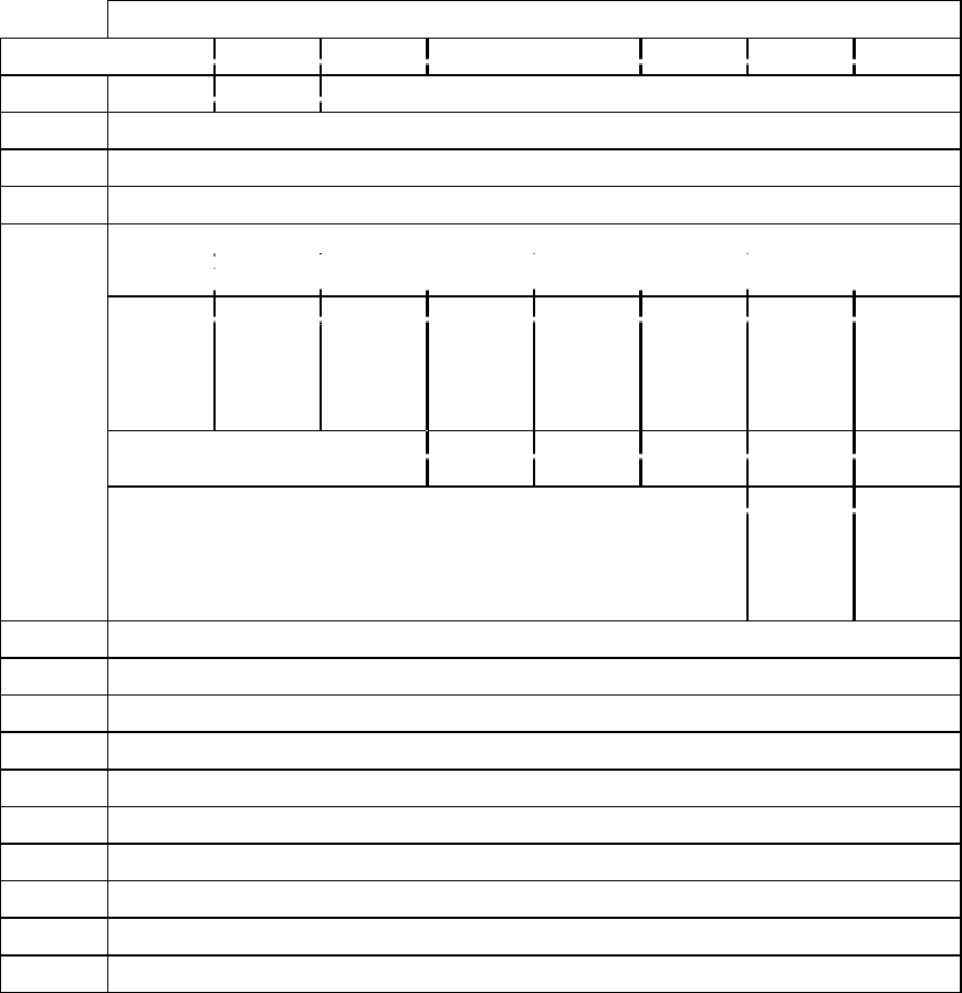
CD-ROM SCSI-2 COMMAND REFERENCE MANUAL VERSION 3.1 (OB-U0077C)
- 54 -
TABLE 2-9-7 PAGE CODE 2AH - CD-ROM CAPABILITIES AND MECHANICAL STATUS
PAGE FORMAT
Bit
Byte 76543210
0Reserve Reserve Page Code (2Ah)
1Page Length (0Eh)
2Reserved
3Reserved
4 ~ 7 Reserve Multi-
Session
Mode 2
From2
Mode 2
Form1
Reserve Reserve 0Audio
Play
32-bit
field of
Capabilit
y Bits
Reserve ISRC UPC C2
Pointer
are
supported
R-W De-
interleave
d &
corrected
R-W
supported
CD-DA
Stream is
Accurate
CD-DA
Comman
d
Supporte
d
Loading Mechanism Type Reserve Eject Prevent
Jumper Lock
State Lock
Reserved Separate
Channel
Mute-
Supporte
d
Separate
Volume
Levels
per
Channel
8(MSB) Maximum Speed Supported (in KBps)
9 (LSB)
10 (MSB) Maximum Speed Supported (in KBps)
11 (LSB)
12 (MSB) Buffer Size Supported by Drive (in Kbytes)
13 (LSB)
14 (MSB) Current Speed Selected (in KBps)
15 (LBS)
16 Reserved for number of ADPCM Decoders
17 ~ 20 Reserved
CD-ROM Capabilities and Mechanical Status Page
- 55 -
2.9.7 CD-ROM Capabilities and Mechanical Status Page
IMPORTANT: This command applies only to models DRM-602X, DRM-624X, DR-
U124X, DR-UA124X
The individual capabilities of the drive are specified by bytes 4 through 7. Each of the
bits indicate if that specific capability is supported. A value of zero indicates that the
capability is NOT supported; a value of one indicates the capability IS supported.

CD-ROM SCSI-2 COMMAND REFERENCE MANUAL VERSION 3.1 (OB-U0077C)
- 56 -
TABLE 2-9-7A PARAMETER DESCRIPTION
Bit Parameter Description
0Audio Play The drive is capable of Audio Play operation. This also indicates
that the drive is capable of overlapping Play and other commands
such as reading of the Sub-channel information.
1XA Commands Supported This bit has been reserved for future support of CD-ROM XA
commands. Drives which set this bit shall support all CD-ROM XA
commands.
4Mode 2 Form1 The drive is capable of reading sectors in Mode 2 Form 1(XA)
format.
5Mode 2 Form2 The drive is capable of reading sectors in Mode 2 Form 2 format.
6Multi-Session The drive is capable of reading multiple session or Photo-CD discs.
8READ CD-DA Red Book audio can be read using the READ-CD command.
9CD-DA Stream is Accurate This bit indicates that the drive supports an advanced feature that
allows it to return to an audio location without losing place to
continue the READ CD-DA command.
0The drive is incapable of accurately restarting the CD-DA
read operation , and a BUFFER OVERFLOW error shall
be reported whenever a loss of streaming occurs, This
error will be fatal and the command will have to be
repeated from the beginning.
1The drive can continue from a loss of streaming condition
and no error will be generated.
10 R-W Supported The commands that return Sub-channel data can return the
combined R-W information.
11 R-W De-Interleaved &
Correction
This indicates that the R-W sub-channel data will be returned de-
interleaved and error corrected.
12 C2 Pointers are Supported This indicates that the drive supports the C2 Error Pointers . This
also indicates that the drive is capable of returning the C2 Error
Pointers and C2 Block Error flags in the READ CD command.
13 UPC The drive can return the Media Catalog Number (UPC).
14 ISRC The drive can return the International Standard Recording Code
Information.
16 Lock The PREVENT/ALLOW command is capable of actually locking
the media into the drive.
17 Lock State This Indicates the current state of the drive.
0The drive is currently in the allow (Unlocked ) state.
Media may be inserted or ejected.
1The drive is currently in the prevent (Locked) state.
Media loaded in the drive may not be removed via a soft
or hard eject. If the drive is empty, media may not be
inserted if the Prevent Jumper is not present. If the jumper
is present, then media may be inserted.
18 Prevent Jumper This indicates the state of the (Optional) Prevent / Allow Jumper.
0Jumper is present. Drive will power up to the allow state.
Locking the drive with the Prevent /Allow Command shall
NOT prevent the insertion of media
1Jumper is not present. Drive will power up to the Prevent
State (Locked). The drive will not accept new media or
allow the ejection of media already loaded until an allow
command is issued.
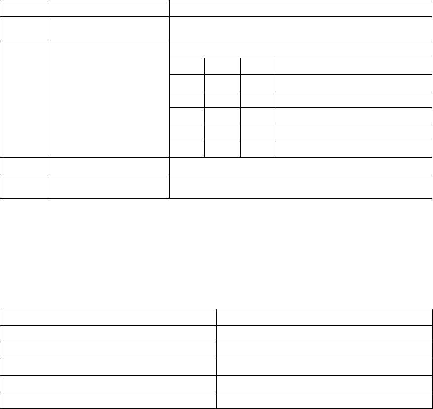
CD-ROM Capabilities and Mechanical Status Page
- 57 -
TABLE 2-9-7A PARAMETER DESCRIPTION (CONTINUED)
Bit Parameter Description
19 Eject Command The drive can eject the disc via the normal START/STOP command
with the LoEj bit set.
23 ~ 21 Loading Mechanism Type This field specifies the type of disc loading the drive supports.
23 22 21
000Caddy type loading mechanism
001Tray type loading mechanism
010Pop-up type loading mechanism
011Reserved
1X X Reserved
24 Separate Volume Levels The audio level for each channel can be controlled independently.
24 Separate Channel Mute The mute capability for each channel can be controlled
independently.
TABLE 2-9-7B EXAMPLE DATA RATES
Speed Data Rate
X1 176 Kbytes / second
X2 353 Kbytes / second
X2.2 387 Kbytes / second
X3 528 Kbytes / second
X4 706 Kbytes/second
The Maximum Speed Supported field indicates the actual maximum data rate that the
drive supports. This value is returned as the number of kilobytes per/second
(Speed/1000) that the data is read from the drive.
Note that these are the raw data rates and do not reflect any overhead resulting from
headers, error correction data, etc. It is also important to understand that the reported
data rate is a theoretical maximum and the actual data rates to the host will be lower.
The Number of Volume Levels Supported field returns the number of discrete levels. If
the drive only supports turning audio on and off, the Number of Volume Levels field
shall be set to 2.
CD-ROM SCSI-2 COMMAND REFERENCE MANUAL VERSION 3.1 (OB-U0077C)
- 58 -
(this page has been left intentionally blank)
CD-ROM Capabilities and Mechanical Status Page
- 59 -
The Buffer Size Supported field returns the number of bytes of buffer dedicated to the
data stream returned to the Host Computer. This value is returned in Kbytes
(Size/1024). If the drive does not have a buffer cache, the value returned shall be zero.
The Current Speed Selected field indicates the actual data rate that the drive is
currently using. This value is returned as the number of kilobytes per/second
(Speed/1000) that the data is read from the drive.

CD-ROM SCSI-2 COMMAND REFERENCE MANUAL VERSION 3.1 (OB-U0077C)
- 60 -
TABLE 2-9-8 PAGE CODE 31H - DRIVE SPEED PAGE
Bit
Byte 76543210
0Reserved Page code (31h)
1Parameter Length (02h)
2Speed
3Reserved
TABLE 2-9-8A SPEED FIELD VALUES
Value Description
00h Normal Speed
01h 2X Speed
03h 4X Speed
FFh Maximum Speed
Other Value Maximum Speed
Drive Speed Page
- 61 -
2.9.8 Drive Speed Page
The speed field provides a means for the initiator to set and retrieve the spindle speed
when accessing data areas. The speed field values are listed in Table 2-9-8A on the
opposite page.
The speed setting is only applicable when reading data areas. The target will
automatically switch to normal speed when playing audio tracks and will switch back
to the speed setting when accessing data.
DRIVE NOTES:
DRM-602x
The DRM-602x does not support 4x speed. A speed setting value of 03h
will not cause an error, but set the drive to 2x speed.
DRM-624x, DRM-604X, DR-U124X, DR-UA124X, DR-D504X
These drives do not support 2x Speed. A speed setting value of 01h will not
cause an error.
However, the drive will automatically be set to 4x speed.

CD-ROM SCSI-2 COMMAND REFERENCE MANUAL VERSION 3.1 (OB-U0077C)
- 62 -
TABLE 2-9-9 PAGE CODE 3EH - LOGICAL UNIT ASSIGNMENT LIST
Bit
Byte 76543210
0Reserve Reserve Page Code (3Eh)
1Page Length : (06h)
2 0 Number of supported discs (MSB) : (00h)
3Number of supported discs (LSB) : (06h)
4Disc number for logical unit0
5Disc number for logical unit1
6Disc number for logical unit2
7Disc number for logical unit3
8Disc number for logical unit4
9Disc number for logical unit5
Logical Unit Assignment Page
- 63 -
2.9.9 Logical Unit Assignment Page
Number of supported discs
The drive supports 6 discs. 0006h is always returned, and 124x will return 1 .
Disc numbers
Shows the disk number assigned to each logical unit. Disc number 0 means that the
associated logical unit cannot be used. Disc numbers in defaults are 1 through 6 for
logical units 0 through 5, respectively.
Accessing, with other SCSI commands, a logical unit to which disc number 0 has been
assigned results in a Check Condition status with the sense data of "Illegal logical unit
number."
This page shows the parameters of the drive. The logical unit number specified in the
command descriptor block is ignored.

CD-ROM SCSI-2 COMMAND REFERENCE MANUAL VERSION 3.1 (OB-U0077C)
- 64 -
TABLE 2-10 PAUSE/RESUME (4BH)
Bit
Byte 76543210
0Operation Code (4Bh)
1Logical Unit No. Reserved
2Reserved
3Reserved
4Reserved
5Reserved
6Reserved
7Reserved
8Reserved Resume
9Reserved
Pause/Resume
- 65 -
2.10 Pause/Resume (4Bh)
Operation Code is (4Bh)
Resume
A Resume of zero indicates that the drive enter the hold track state with the audio output
muted. A Resume bit of one indicates that the drive release the pause and begin play at the
block following the last block played.
The PAUSE/RESUME command requests that the drive start or stop the current audio play
operation. This command is used with PLAY AUDIO commands, issued while the immediate
bit(Immed) of MODE SELECT PAGE CODE E is set to one.
This command is terminated with Check Condition status if the resume bit is zero and the audio
play operation cannot be paused (i.e. an audio play operation has not been requested, or the
requested audio play operation has been completed).
It will not be considered an error to request a pause when a pause is already in effect or to request
a resume when a play operation is in progress.

CD-ROM SCSI-2 COMMAND REFERENCE MANUAL VERSION 3.1 (OB-U0077C)
- 66 -
TABLE 2-11 PLAY AUDIO(10) (45H)
Bit
Byte 76543210
0Operation Code (45h)
1Logical Unit No. Reserved
2Starting Logical Block Address (MSB)
3Starting Logical Block Address
4Starting Logical Block Address
5Starting Logical Block Address (LSB)
6Reserved
7Transfer Length (MSB)
8Transfer Length (LSB)
9Reserved
Play Audio(10)
- 67 -
2.11 Play Audio(10) (45h)
Operation Code is (45h).
Logical Block Address
The logical block address field specifies the logical block at which the audio play back
operation will begin. If all bytes in the logical block address field are set to FFh, it means
to start at the current optical head location. This feature allows the host to modify the audio
ending address without interrupting the current audio playback operation.
Transfer Length
Specifies the number of contiguous logical blocks that will be played. A transfer length
field of zero indicates that no audio operation will occur. This condition will not be
considered an error. Any other value indicates the number of logical blocks that will be
played.
The PLAY AUDIO(10) command requests that the target play audio starting at the specified
logical block address for the specified transfer length. The command function (Immed bit) and
the output of audio signals will be as specified by the settings of the audio control parameters in
the MODE SELECT PAGE CODE E.
The status returning condition depends on the Immed bit of MODE SELECT page code E. The
Immed bit in MODE SELECT page code E of one requests that this command return the status
byte as soon as the audio playback operation has been started. The Immed bit in MODE
SELECT page code E of zero requests that this command return the status byte when audio
playback operation is completed, or an error occurs.
If any commands related to audio operations are implemented then the PLAY AUDIO command
will be implemented to allow a method for the initiator to determine if audio operations are
supported. A target responding to a PLAY AUDIO command which has transfer length of zero
with Check Condition status and setting the sense key to ILLEGAL REQUEST does not support
audio play operations.

CD-ROM SCSI-2 COMMAND REFERENCE MANUAL VERSION 3.1 (OB-U0077C)
- 68 -
TABLE 2-12 PLAY AUDIO(12) (A5H)
Bit
Byte 76543210
0Operation Code (A5h)
1Logical Unit No. Reserved
2Logical Block Address (MSB)
3Logical Block Address
4Logical Block Address
5Logical Block Address (LSB)
6Transfer Length (MSB)
7Transfer Length
8Transfer Length
9Transfer Length (LSB)
10 Reserved
11 Reserved
Play Audio(12)
- 69 -
2.12 Play Audio(12) (A5h)
Operation Code is (A5h).
The PLAY AUDIO(12) command requests that the drive begin an audio playback operation. The
command function (Immed and SOTC bits) and the output of audio signals shall be specified by
the settings of the mode parameters. See the PLAY AUDIO(10) command for a description of
the fields in this command.

CD-ROM SCSI-2 COMMAND REFERENCE MANUAL VERSION 3.1 (OB-U0077C)
- 70 -
TABLE 2-13 PLAY AUDIO MSF (47H)
Bit
Byte 76543210
0Operation Code (47h)
1Logical Unit No. Reserved
2Reserved
3Starting M Field
4Starting S Field
5Starting F Field
6Ending M Field
7Ending S Field
8Ending F Field
9Reserved
Play Audio MSF
- 71 -
2.13 Play Audio MSF (47h)
Operation Code is (47h)
Starting M/S/F Field
Specifies absolute starting address in minutes, seconds, frame number.
Ending M/S/F Field
Specifies absolute ending address in minutes, seconds, frame number.
The PLAY AUDIO MSF command requests the target to begin an audio playback operation.
The command function (Immed) and the output of audio signals shall be as specified by the
settings of the mode parameters page code 0Eh.
The Starting M Field, the Starting S Field, and the Starting F Field specify the absolute MSF
address at which the audio play operation shall begin.
The Ending M Field, the Ending S Field, and the Ending F Field specify the absolute MSF
address at which the audio play operation shall end.
All contiguous audio sectors between the starting and the ending MSF address shall be played.
A starting MSF address equal to an ending MSF address causes no audio play operation to occur.
This is not considered an error. If the starting MSF address is less than the ending MSF address,
the command shall be terminated with Check Condition status. The sense key shall be set to
ILLEGAL REQUEST.
If the starting address is not found, or if the address is not within an audio track, or if a not ready
condition exists, the drive will terminate with a Check Condition status. If the SOTC bit
parameter in the MODE SELECT command page code 0Eh is one, the drive will stop if during
the specified starting and ending addresses, a track crossing occurs.

CD-ROM SCSI-2 COMMAND REFERENCE MANUAL VERSION 3.1 (OB-U0077C)
- 72 -
TABLE 2-14 PLAY AUDIO TRACK INDEX (48H)
Bit
Byte 76543210
0Operation Code(48h)
1Logical Unit No. Reserved
2Reserved
3Reserved
4Starting Track
5Starting Index
6Reserved
7Ending Track
8Ending Index
9Reserved
Play Audio Track Index
- 73 -
2.14 Play Audio Track Index (48h)
Operation Code is (48h).
Starting Track/Index
The starting track field specifies the track number of the starting audio track. The starting
index field specifies the index number within the track at which the audio play operation
shall begin.
Ending Track/Index
The ending track field specifies the track number of the ending audio track. The ending
index field specifies the index number within the track after which the audio play operation
shall stop. The audio play operation shall terminate at the last block with an index number
equal to the ending index. All contiguous audio sectors between the starting and ending
address shall be played.
The PLAY AUDIO TRACK INDEX command requests the drive begin an audio play operation.
The command function (Immed) and the output of audio signals shall be specified by the settings
of the mode parameters page code 0Eh.
If the starting address is less than the ending address, the command will be terminated with
Check Condition sense key set to ILLEGAL REQUEST.
If the starting address is not found, or if the address is not within an audio track, or if a not ready
condition exists, the command shall be terminated with Check Condition status. Valid values for
the track and index fields are 1 to 99.
If the ending track is greater than the last information track on the media, the playback will
continue until the last track is complete. If the ending index is greater than the largest index value
on the ending track, the playback shall continue until this track is complete then terminate.
These conditions are not considered errors.
If the starting index is greater than the largest index value on the starting track, and the stop on
track crossing (SOTC) bit of the audio control MODE SELECT parameters page code 0Eh is
zero, the playback operation will start at the beginning of the next track.
If the starting index is greater than the largest index value on the starting track, and the stop on
track crossing (SOTC) bit of the audio control MODE SELECT parameters page is one, the
playback shall not begin. The target shall return Check Condition, and the sense key set to
ILLEGAL REQUEST.

CD-ROM SCSI-2 COMMAND REFERENCE MANUAL VERSION 3.1 (OB-U0077C)
- 74 -
TABLE 2-15 PLAY AUDIO TRACK RELATIVE(10) (49H)
Bit
Byte 76543210
0Operation Code (49h)
1Logical Unit No. Reserved
2Track Relative Logical Block Address (MSB)
3Track Relative Logical Block Address
4Track Relative Logical Block Address
5Track Relative Logical Block Address (LSB)
6Starting Track
7Transfer Length (MSB)
8Transfer Length (LSB)
9Reserved
Play Audio Track Relative(10)
- 75 -
2.15 Play Audio Track Relative(10) (49h)
Operation Code is (49h).
TRLBA
The Track Relative Logical Block Address field specifies the two's complement starting
logical block address relative to the beginning of the first sector on the track with an index
value of one. Negative values indicate a starting location within the audio pause area at the
beginning of the requested track.
Starting Track
Specifies the track number of the starting audio track.
Transfer Length
The Transfer Length Field specifies the number of contiguous logical blocks that shall be
output as audio data. A length of zero indicates that no audio playback operation shall
occur. This condition is not an error. Any other value indicates the number of logical
blocks that shall be output.
The PLAY AUDIO TRACK RELATIVE(10) command requests that the drive begin an audio
playback operation. The starting address is specified as a track relative logical block address
within the specified starting track. The command function (Immed and SOTC bits) and the
output of audio signals shall be as specified by the settings of the mode parameters.
If the logical block length is not equal to the sector size the drive will adjust the starting logical
block address and the transfer length. The drive will start the audio play operation with the
beginning of a sector whenever the starting logical address falls within that sector (MSF unit). If
the requested transfer length causes the end of an audio play operation to fall within a sector the
drive will continue the play operation through the end of that sector.
If the starting address is not found, or if the address is not within an audio track, or if a not ready
condition exists, the command is terminated with Check Condition status.

CD-ROM SCSI-2 COMMAND REFERENCE MANUAL VERSION 3.1 (OB-U0077C)
- 76 -
TABLE 2-16 PLAY AUDIO TRACK RELATIVE(12) (A9H)
Bit
Byte 76543210
0Operation Code(A9h)
1Logical Unit No. Reserved
2Track Relative Logical Block Address (MSB)
3Track Relative Logical Block Address
4Track Relative Logical Block Address
5Track Relative Logical Block Address (LSB)
6Transfer Length (MSB)
7Transfer Length
8Transfer Length
9Transfer Length (LSB)
10 Starting Track
11 Reserved
Play Audio Track Relative(12)
- 77 -
2.16 Play Audio Track Relative(12) (A9h)
Operation Code is (A9h).
The PLAY AUDIO TRACK RELATIVE(12) command requests that the device begin an audio
playback operation. The command function (Immed and SOTC bits) and the output of audio
signals shall be as specified by the settings of the mode parameters. See the PLAY AUDIO
TRACK RELATIVE(10) command for a description of the fields in this command.

CD-ROM SCSI-2 COMMAND REFERENCE MANUAL VERSION 3.1 (OB-U0077C)
- 78 -
TABLE 2-17 PREVENT/ALLOW MEDIA REMOVAL (1EH)
Bit
Byte 76543210
0Operation Code (1Eh)
1Logical Unit No. Reserved
2Reserved
3Reserved
4Reserved Prev
5Reserved
Prevent/Allow Media Removal
- 79 -
2.17 Prevent/Allow Media Removal (1Eh)
Operation code is (1Eh).
Prev (Prevent bit)
When this bit is set to 1, EJECT DISK commands (C0h) and the Eject Button on the drive
are ignored. When it is 0, media removal is allowed.
This command is used to prevent or allow media removal from the drive. If an EJECT DISK
command is received when media removal is prevented, a Check Condition is returned with the
sense key "Illegal request" and the extended sense code of 80h (Medium Change Prohibited).
The prevented condition is released when a BUS DEVICE RESET message is received or a
hardware reset occurs.

CD-ROM SCSI-2 COMMAND REFERENCE MANUAL VERSION 3.1 (OB-U0077C)
- 80 -
TABLE 2-18 READ(6) (08H)
Bit
Byte 76543210
0Operation Code (08h)
1Logical Unit No. Logical block address (MSB)
2Logical block address
3Logical block address (LSB)
4Transfer Length
5Reserved
Read(6)
- 81 -
2.18 Read(6) (08h)
Operation Code is (08h).
This six-byte READ command only allows reads of up to 255 blocks.
The logical blocks will have the length set by MODE SELECT or the power-on default. For
longer reads, use the ten-byte READ(10) command.
After a read operation, the drive holds the head at the last read track until an inactivity time-out
occurs.

CD-ROM SCSI-2 COMMAND REFERENCE MANUAL VERSION 3.1 (OB-U0077C)
- 82 -
TABLE 2-19 READ(10)
Bit
Byte 76543210
0Operation Code (28h)
1Logical Unit No. Reserved
2Logical block address (MSB)
3Logical block address
4Logical block address
5Logical block address (LSB)
6Reserved
7Logical block length (MSB)
8Logical block length (LSB)
9Reserved
Read(10)
- 83 -
2.19 Read(10)
Operation code is (28h).
This ten byte READ command allows reads of up to 64K blocks. The logical blocks will have
the length set by MODE SELECT or the power-on default.
After a read operation, the drive holds the head at the last read track until an inactivity time-out
occurs.
NOTE: The DPO, FUA and RelAdr bits (not shown) in byte 1 are not supported, and must be
set to 0.
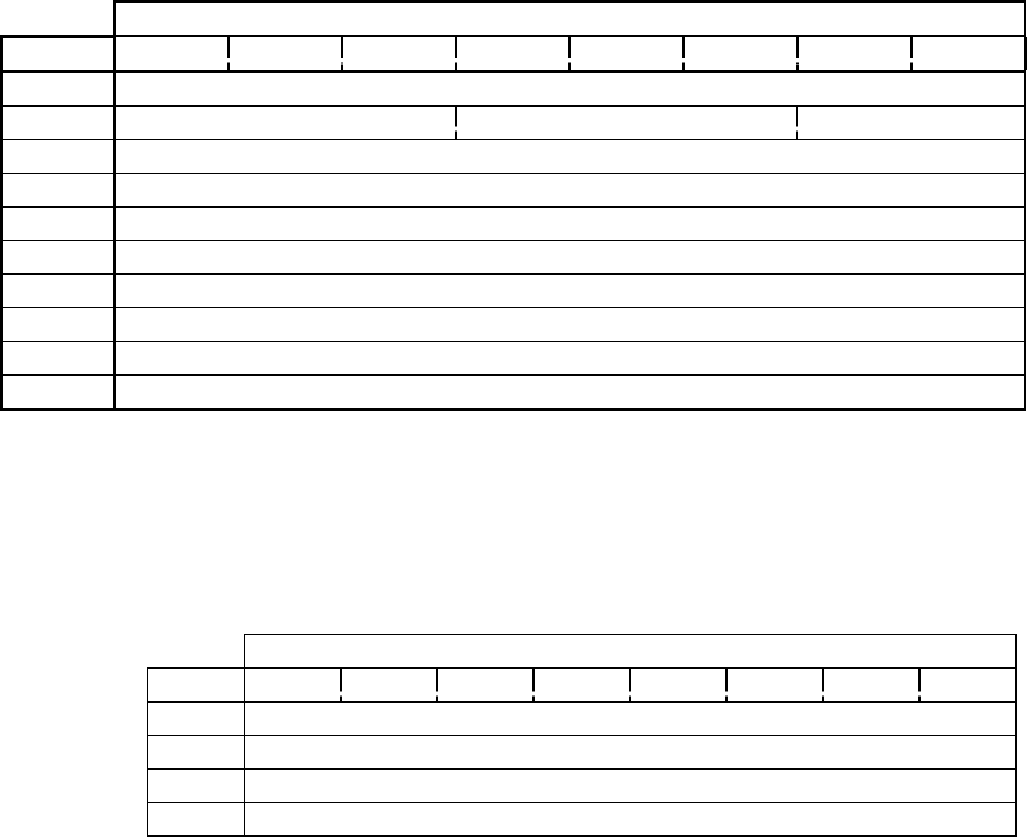
CD-ROM SCSI-2 COMMAND REFERENCE MANUAL VERSION 3.1 (OB-U0077C)
- 84 -
TABLE 2-20 READ BUFFER (3CH)
Bit
Byte 76543210
0Operation Code (3Ch)
1Logical Unit No. Reserved Mode
2Buffer ID : (00h)
3Buffer offset (MSB)
4Buffer offset
5Buffer offset (LSB)
6Allocation length (MSB)
7Allocation length
8Allocation length (LSB)
9Control/Reserved
TABLE 2-20AREAD BUFFER HEADER
Bit
Byte 76543210
0Reserved
1Effective length (MSB)
2Effective length
3Effective length (LSB)
Read Buffer
- 85 -
2.20 Read Buffer (3Ch)
Operation Code is (3Ch).
Mode specifies meaning of the Buffer Offset field.
Buffer ID is not supported. This byte is always 00h.
Buffer Offset
The byte offset in the buffer at which the read shall begin. This must be between 0 and 15.
Allocation Length must include 4 byte header.
This command is used with the WRITE BUFFER command to test the reliability of the drive
command buffer memory and of the SCSI bus. This command does not cause a disc access. The
drive terminates the DATA IN phase when it has transferred the header and data specified in
Allocation Length, or the header and the remainder of the buffer.
Mode field Definition
00b The header, data, and buffer offset are 0s.
01b The buffer offset indicates the offset from the start of the
buffer at which the data are to be read.
10b Reserved
11b Reserved
The 4-byte header and the following data are transferred to the initiator in the DATA IN phase.
If Allocation Length is 0, neither the header nor data are transferred.
The header is defined as follows:
- Effective Length
The number of bytes of valid data in the buffer.
The effective length does not depend on the actual number of data written by a WRITE BUFFER
command. The sum of the buffer offset plus the effective data length is always 16. The number
of data to be transferred following the header is the smaller one, either the allocated length minus
4 bytes, or the effective length.
When the drive cannot accept the specified buffer offset, a Check Condition is returned with the
sense key "ILLEGAL REQUEST." If Buffer Offset is not 0 when Mode is set to 00h, Check
Condition is returned.
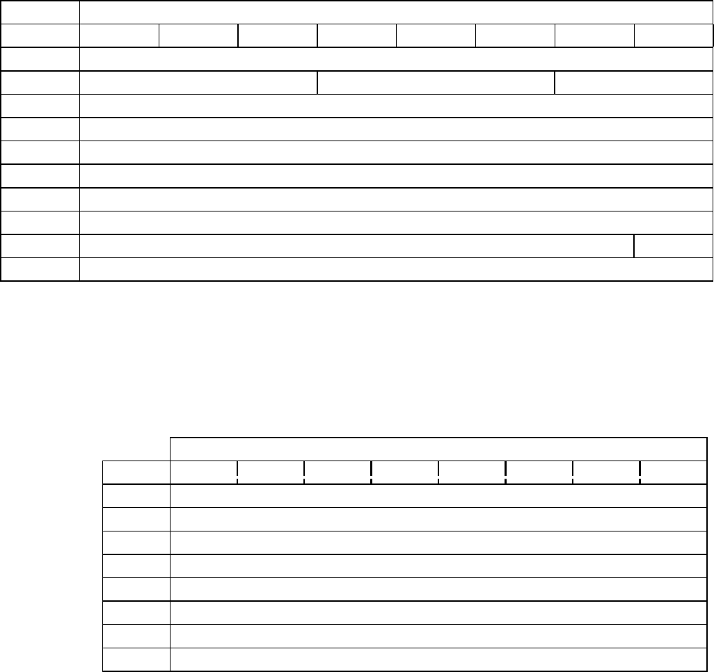
CD-ROM SCSI-2 COMMAND REFERENCE MANUAL VERSION 3.1 (OB-U0077C)
- 86 -
TABLE 2-21 READ CD-ROM CAPACITY (25H)
Bit
Byte 76543210
0Operation Code (25h)
1Logical Unit No. Reserved RelAdr (0)
2Logical block address (MSB) (00h)
3Logical block address (00h)
4Logical block address (00h)
5Logical block address (LSB) (00h)
6Reserved
7Reserved
8Reserved PMI (0)
9Reserved
TABLE 2-21AREAD CAPACITY DATA
Bit
Byte 76543210
0Logical block address (MSB)
1Logical block address
2Logical block address
3Logical block address (LSB)
4Logical block length (MSB)
5Logical block length
6Logical block length
7Logical block length (LSB)
Read CD-ROM Capacity
- 87 -
2.21 Read CD-ROM Capacity (25h)
Operation code is (25h).
This command requests the drive to return physical parameters of the CD-ROM disc currently
loaded. The Logical Block Address, RelAdr (Byte 1, bit 0), and PMI (Byte 8, bit 0) parameters
are not supported and must be set to 0.
The drive sends the initiator the 8-byte data as shown in Table 2-3 in the data transfer phase.
Logical block address is the last logical block address on the disc.
Logical block length is the size of logical blocks in bytes.
The value of Logical Block Length returned depends on the block length set with a MODE
SELECT command. The default value of the block length is 2048 bytes. The CD-ROM drives
allow values of 2048 or 512 bytes to be set with an external switch on the drive.
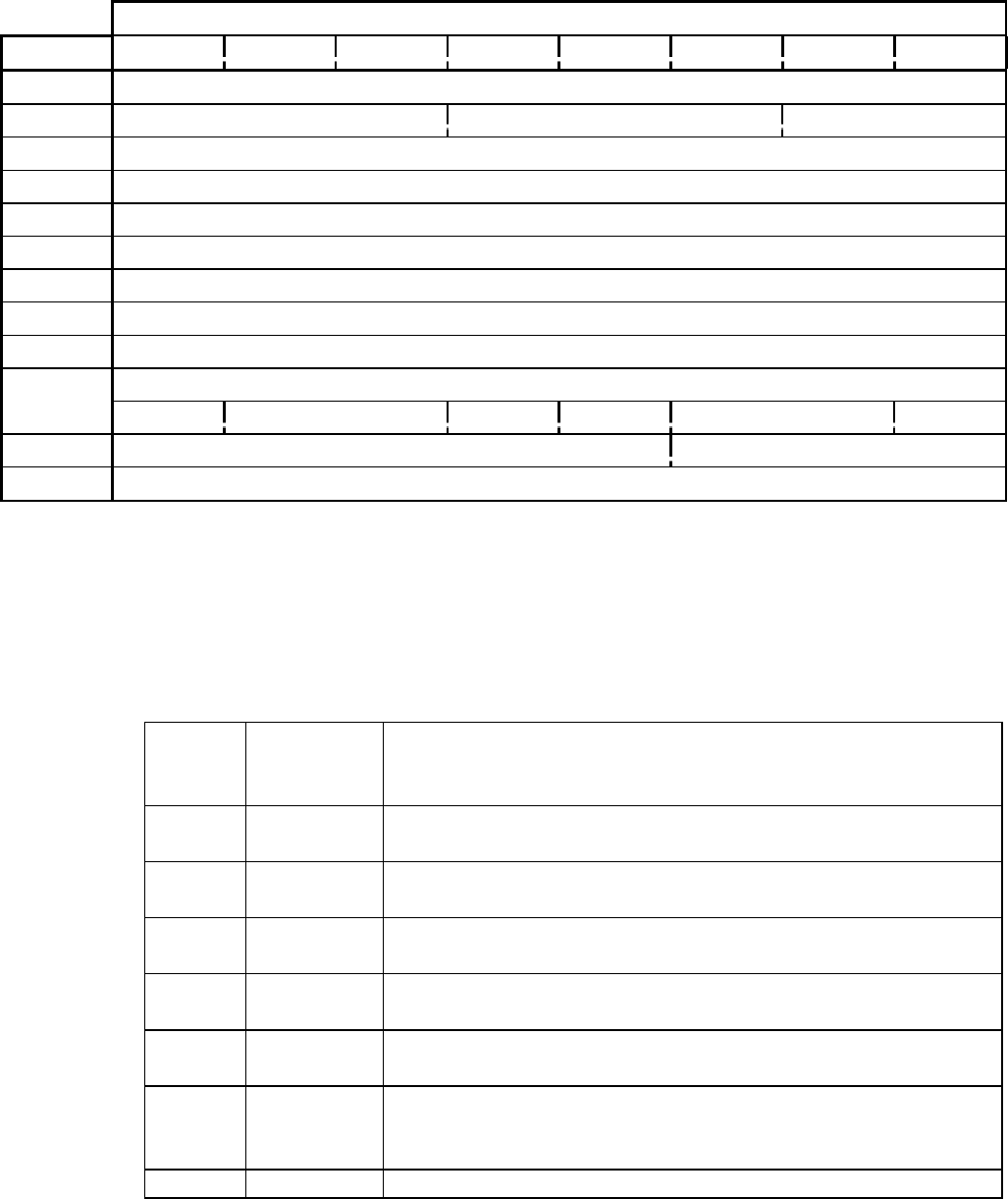
CD-ROM SCSI-2 COMMAND REFERENCE MANUAL VERSION 3.1 (OB-U0077C)
- 88 -
TABLE 2-22 READ CD (BEH)
Bit
Byte 76543210
0Operation Code (BEh)
1Reserved Expected Sector Type Reserved
2(MSB)
3Starting Logical Block Address
4
5 (LSB)
6(MSB)
7Transfer Length in Blocks
8 (LSB)
9Flag Bits
Synch Field Header(s) Code User Data EDC&ECC Error Flag(s) Reserve
10 Reserved Sub-Channel Data Selection Bits
11 Reserved
TABLE 2-22AREAD-CD, EXPECTED SECTOR TYPE FIELD DEFINITION
Expected
Sector
Type
Definition Description
000b Any Type Checking of the Sector Type is not performed. Device will terminate
command at sector where transition between CD-ROM and CD-DA occurs.
001b CD-DA Only Red Book (CD-DA) sectors allowed. Attempt to read any other format
results in error report.
010b Mode 1 Form 1 Only Yellow Book sectors having “user” data field of 2048 bytes allowed.
Attempt to read any other format results in an error report.
011b Mode 1 Form 2 Only Yellow Book sectors having “user” data field of 2336 bytes allowed.
Attempt to read any other format results in an error report.
100b Mode 2 Form 1 Only Green Book sectors having “user” data field of 2048 bytes allowed.
Attempt to read any other format results in an error report.
101b Mode 2 Form 2 Only Green Book sectors having “user” data field of 2324 bytes allowed.
Attempt to read any other format results in an error report. Note: the spare
data is included in the user data making the size 2324+4 =2328 bytes.
110b~111b Reserved
Read CD-ROM Capacity
- 89 -
2.22 Read CD (BEh)
IMPORTANT: This command applies only to models DRM-602X, DRM-624X, DR-U124X,
DR-UA124X
Operation code is (BEh).
The Expected Sector Type field is used to limit the amount of information returned to the Host.
If the Requested Sector(s) do not match the specified type , the command will be terminated with
a Check Condition. The Sector that does not match will not be transferred to the Host. The sense
key shall be set to ILLEGAL MODE TOR THIS TRACK.
The Synch Field Bit, when set to one indicates that the Synch Field from the sector will be
included in the data stream. Note that the data fields that are requested to be included in the data
stream shall be contiguous. The Synch Field information (if selected) will be the first information
in the data stream; all other fields will follow.
The Header(s) Code is an encoded field that indicates the Header / Sub-header information to be
placed in the data stream.
The User Data Flag, when set to one, indicates that the Data part of a CD Sector shall be
returned in the data stream. When set to 1, the whole user data will be returned to the host. Note
that the setting of the Mode Select Density Code does not apply to this command, and the
physical user data will be returned . If the current track is an Audio Track then the Audio Data
will be returned, else the normal CD-ROM data will be returned. The possible data lengths are
2048,2336,2328 and 2352.
The EDC and ECC Flag, when set to one, indicates that the EDC and ECC (L-EC) field shall be
included in the data stream. For Mode 1 CDs this will include the 8 bytes of pad data.
Error Flag(s) is an encoded field that indicates which (if any) of the C2 and / or Block Error
data will be included in the data stream. All the field types are mandatory. If the drive does not
support the C2 pointers (as reported in the Mode sense Capabilities page) the data returned shall
be zero filled.
The Sub-Channel Data Selection bits indicate which CD Sub-Channel information is to be
included in the data stream., the “}Raw”} Sub-Channel information (All eight channels , on byte
from each of the small frames.) If the bit is set , then that Sub-channel data will be included in
the data stream to the Host.

CD-ROM SCSI-2 COMMAND REFERENCE MANUAL VERSION 3.1 (OB-U0077C)
- 90 -
TABLE 2-22BREAD CD, HEADER CODE FIELD DEFINITION
Header(s) Code Definition Description
00b None None of the header data shall be placed in the data stream.
01b Header Only Only the mode 1 or Form 1 4-byte header will be returned in
the data stream.
10b Sub-header Only Only the Mode 2 Form 1 of 2 Sub-header will be placed into
the data stream.
11b All Headers Both the Header and Sub-header will be placed in the data
stream.
TABLE 2-22CREAD CD, ERROR FLAG FIELD DEFINITION
Error Flags Definition Description
00b None No Error information will be included in the data stream.
01b C2 Error Flag data The C2 Error flag (Pointer) bits (2352 bits or 294 bytes)
will be included in the data stream. When the C2 Error
pointer bits are included in the data stream, there will be
one bit for each byte in error in the sector (2352 total).
The bit ordering is from the most significant bit to the
least significant bit in each byte . The first bytes in the
sector will be the first bits/bytes in the data stream.
10b C2 & Block Error Flags Both the C2 Error Flags (2352 bits or 294 bytes) and the
Block Error Byte will be included in the data stream.
The Block Error byte is just the longitudinal parity of all
the C2 Error Flag bytes, So that the data stream will
always be an even number of bytes, the Block Error byte
will be padded with a 0 byte. The Block Error byte will
be first in the data stream followed by the pad byte.
11b Reserved Reserved for future enhancement.
Read CD-ROM Capacity
- 91 -
Support of Sub-channel data is optional. In the case of R-W the drive may return data de-
interleaved and error-corrected, RAW or padded with zeros depending on the R-W Supported
and R-W de-interleaved and error-corrected bits in the CD-ROM capabilities and mechanical
status page.
If the Starting Logical Block Address is set to FFFFFFFFh and the only information requested to
be placed in the data stream is the Sub-channel data and there is currently a PLAY AUDIO
command in process, the actual address used will be from the current location (of the Audio
play).
The number of bytes returned is based on which bits are set in the Data Selection Field.
The table on the opposite page allows you to calculate the number of bytes returned based on
which Data Selection field bits are set.
The CD-DA audio data includes 16bits of information for each channel, and will be formatted as
follows when an audio track is read. The First Channel is Left channel, and Right channel is
next.

CD-ROM SCSI-2 COMMAND REFERENCE MANUAL VERSION 3.1 (OB-U0077C)
- 92 -
TABLE 2-22DREAD CD, SUB CHANNEL DATA SELECTION FIELD DEFINITION
Sub-channel Definition Description
000b No Sub channel Data No Sub-channel data will be transferred
001b RAW Raw Sub-channel data will be transferred
010b QNot Supported
011b Reserved
100b R - W R-W data will be transferred
101b-111b Reserved
TABLE 2-22ENUMBER OF BYTES RETURNED BASED ON DATA SELECTION FIELD
Flag Bits CD-DA Mode 1
Form 1
Mode 1
Form 2
Mode 2
Form1
Mode 2
Form1
Sync 80h 0 12 12 12 12
Header 20h 0 4 4 4 4
Sync & Header A0h 0 16 16 16 16
Sub Header 40h 0 0 0 8 8
All Header 60h 0 4 4 12 12
Sync & Headers E0h 0 16 16 24 24
User Data 10h 2352 2048 2336 2048 2328
Sub Header & User Data 50h 2352 2048 2336 2056 2336
Header & User Data 30h 2352 2052 2340 2052 2332
All Headers & User Data 70h 2352 2052 2340 2060 2340
Sync & All Headers & User Data F0h 2352 2064 2352 2072 2352
Repeat All Above and Add EDC/
ECC
08h 0 288 0 280 0
Repeat All Above and Add Error
Flags
02h 294 294 294 294 294
Repeat All Above and Add Block &
Error Flags
04h 296 296 296 296 296
Read CD-ROM Capacity
- 93 -
(this page has been left intentionally blank)

CD-ROM SCSI-2 COMMAND REFERENCE MANUAL VERSION 3.1 (OB-U0077C)
- 94 -
TABLE 2-23 READ CD MSF (B9H)
Bit
Byte 76543210
0Operation Code (B9h)
1Reserved Expected User data type Reserved
2Reserved
3Starting M Field
4Starting S Field
5Starting F Field
6Ending M Field
7Ending S Field
8Ending F Field
9Flag Bits
Synch Field Header(s)Code User Data EDC&ECC Reserved for Error Type Reserve
Reserved Sub-Channel Data Selection Bits
Sub Q Raw Reserved
11 Reserved
Read CD MSF
- 95 -
2.23 Read CD MSF (B9h)
IMPORTANT: This command applies only to models DRM-602X, DRM-624X, DR-U124X,
DR-UA124X
The Starting M field, the Starting S field, and the Starting F field specify the absolute MSF
address at which the Read operation shall begin.
The Ending M field, the Ending S field, and the Ending F field specify the absolute MSF
address where the Read operation shall end. All contiguous sectors between the starting and the
ending MSF address shall be read.
A starting MSF address equal to an ending MSF address prevents a read operation. This shall not
be considered an error. If the starting MSF address is greater than the ending MSF address, the
command shall be terminated with Check Condition status. The sense key shall be set to
ILLEGAL REQUEST.
If the starting address is not found, or if a not ready condition exists, the command shall be
terminated with Check Condition status.

CD-ROM SCSI-2 COMMAND REFERENCE MANUAL VERSION 3.1 (OB-U0077C)
- 96 -
TABLE 2-24 READ CDP (E4H)
Bit
Byte 76543210
0Operation Code (E4h)
1Logical Unit No. Reserved
2Reserved
3Reserved
4Reserved
5Reserved
6Reserved
7Reserved
8Allocation length (MSB)
9Allocation length (LSB)
10 Reserved
11 Reserved
Read CDP
- 97 -
2.24 Read CDP (E4h)
Operation Code is (E4h)
This command requests the drive to return the status data resulting from the previous WRITE
CDP command. The drive terminates the data phase when Allocation Length bytes or all the
relevant data have been transferred.
The last status data returned from the Drive Controller is buffered in the drive SCSI controller.
Because the next return data from the next WRITE CDP command will overwrite the buffer, the
READ CDP command should immediately follow a WRITE CDP command.
The buffered status data is cleared after executing a READ CDP command. If a READ CDP
command is issued after the buffer is cleared, the drive does not go to the data phase, but returns
a GOOD status.
If a READ CDP command is issued during the execution of a player operation, a BUSY status is
returned. Any command other than the READ CDP is accepted. If the drive receives a SCSI
command (except the INQUIRY or REQUEST SENSE commands) the action initiated by the
WRITE CDP command will be terminated. In this case, the player status returned by the READ
CDP command will be "E16" (Input From Other Device). Such a player interrupt does not cause
any SCSI errors.
See Appendix B for information on the CDP return codes.
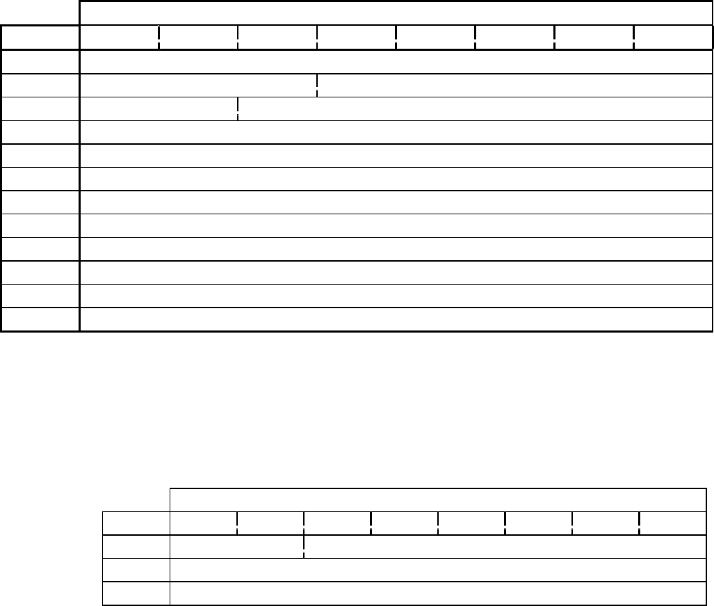
CD-ROM SCSI-2 COMMAND REFERENCE MANUAL VERSION 3.1 (OB-U0077C)
- 98 -
TABLE 2-25 READ DRIVE STATUS (E0H)
Bit
Byte 76543210
0Operation Code (E0h)
1Logical Unit No. Reserved
2PCF Page Code
3Reserved
4Reserved
5Reserved
6Reserved
7Reserved
8Allocation Length (MSB)
9Allocation Length (LSB)
10 Reserved
11 Reserved
TABLE 2-25APAGE HEADER
Bit
Byte 76543210
0Reserved Page Code
1Page Length (MSB)
2Page Length (LSB)
Read CDP
- 99 -
2.25 Read Drive Status (E0h)
Operation Code is (E0h)
PCF (Page Control Field) indicates the type of Page Parameter to be returned.
00b :Current Value
01b :Reserved
10b :Reserved
11b :Reserved
Page Code indicates contents of the Page Parameters.
01h :Drive Status
02h :Audio Play Status
Others :Reserved
The READ DRIVE STATUS command requests the drive to report its specific drive status to the
initiator.
The drive terminates the DATA IN phase when Allocation Length bytes have been transferred or
when all available Drive Status data has been transferred to the initiator. When Allocation
Length is set to 0, no data is returned. This does not cause a Check Condition.
Page Parameters
Each Page Parameter data is preceded by a header of 3 bytes defining the Page Code and
Page Length of the page.
Page Length is the number of bytes of status data following the Header
Page Code 01h
The drive will return 16 bits of Drive Status data. Bit 0 is the least significant bit.
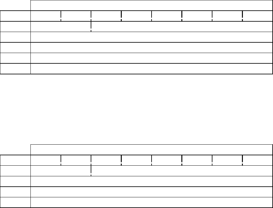
CD-ROM SCSI-2 COMMAND REFERENCE MANUAL VERSION 3.1 (OB-U0077C)
- 100 -
TABLE 2-25BDRIVE STATUS DATA FORMAT
Bit
Byte 76543210
0Reserved Page Code : (01h)
1Page Length (MSB) (00h)
2Page Length (LSB) (02h)
3Drive Status (MSB)
4Drive Status(LSB)
TABLE 2-25CAUDIO PLAY STATUS FORMAT
Bit
Byte 76543210
0Reserved Page Code : (02h)
1Page Length (MSB) (00h)
2Page Length (LSB) (01h)
3Audio Play Status
Read CDP
- 101 -
Drive Status
Bit 15-12 0: Reserved (all 0)
Bit 11 0: Disc is present in Logical unit
1: No disc present in Logical Unit
Bit 10 1: Supports Mode2 form1and form2.(XA)
0: Does not support Mode2 form1 and form2.(XA)
Bit 9 0: Supports HSG addressing mode
1: Supports HSG and Red Book addressing modes
Bit 8 0: No audio channel manipulation
1: Supports audio channel manipulation
Bit 7 0: No Look-Ahead Read function
1: Supports Look-Ahead Read function
Bit 6 0: Reserved
Bit 5 0: Does not support interleaving
1: Supports ISO-9660 interleaving read
Bit 4 0: Data track reads only
1: Data track reads and play audio/video tracks
Bit 3 0: Read only
1: Supports Read and Write commands
Bit 2 0: Supports only 2048-byte block size
1: Supports 2048 and 2353-bytes block size
Bit 1 0: Magazine locked
1: Magazine unlocked
Bit 0 0: Magazine inserted
1: No magazine inserted
Page Code: 02h
The drive returns a 1-byte Audio Play Status.
Audio Play Status is a bit set to 1 indicates that the corresponding Logical Unit is playing an
audio track.
Bit 0 :Logical Unit 0
Bit 1 :Logical Unit 1
Bit 2 :Logical Unit 2
Bit 3 :Logical Unit 3
Bit 4 :Logical Unit 4
Bit 5 :Logical Unit 5
Bit 6 and 7 :Reserved
The Audio Play Status refers only to audio playback operations initiated by AUDIO PLAY
commands.
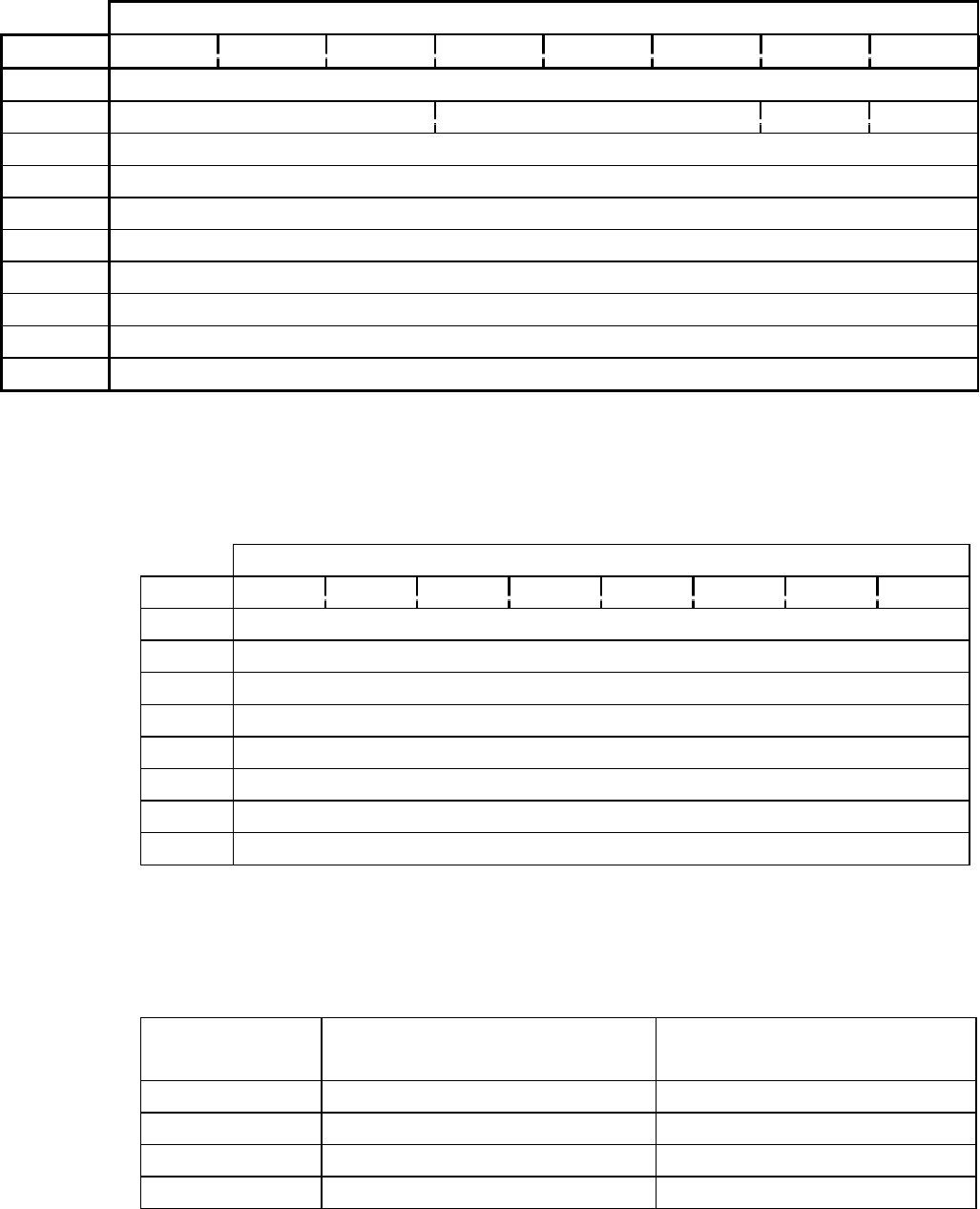
CD-ROM SCSI-2 COMMAND REFERENCE MANUAL VERSION 3.1 (OB-U0077C)
- 102 -
TABLE 2-26 READ HEADER (44H)
Bit
Byte 76543210
0Operation Code (44h)
1Logical Unit No. Reserved MSF Reserve
2Logical block address (MSB)
3Logical block address
4Logical block address
5Logical block address (LSB)
6Reserved
7Allocation Length (MSB)
8Allocation Length (LSB)
9Reserved
TABLE 2-26A HEADER DATA FORMAT
Bit
Byte 76543210
0CD-ROM Data Mode
1Reserved
2Reserved
3Reserved
4Absolute CD-ROM Address (MSB)
5Absolute CD-ROM Address
6Absolute CD-ROM Address
7Absolute CD-ROM Address (LSB)
TABLE 2-26BCD-ROM DATA MODE CODES
CD-ROM Mode User Data Field Contents (2048
Bytes)
Auxiliary Field Contents (288
Bytes)
00 all bytes zero all bytes zero
01 user data EDC, L-EC bytes
02 user data user data
03h ~ FFh reserved reserved
Read Header
- 103 -
2.26 Read Header (44h)
Operation Code is (44h)
MSF
Set to 1 indicates that the absolute CD-ROM address field of the returned header data will
indicate the MSF address where the specified logical block is found.
If MSF bit is equal to 0, the absolute CD-ROM Address field of the returned header data
gives the logical block address of the first logical block in the physical sector where the
specified logical block is found. Note: This address may be different from the specified
logical block address in CDB if the block length is either 512 or 1024 bytes.
Logical Block Address
Specifies the logical block at which the read header operation will begin. A logical block
size smaller than 2048 bytes, will be mapped into the appropriate physical block from
which the data would have been read.
Allocation Length is the length of header data to be returned (08h).
This command requests the drive to return the header data of the specified logical block to allow
the system or applications to determine the mode of the specified block.
If the specified block is on an audio track, a Check Condition status is returned.
CD-ROM Data Mode
The CD-ROM Data Mode field will return CD-ROM Data Mode of the specified logical
block.

CD-ROM SCSI-2 COMMAND REFERENCE MANUAL VERSION 3.1 (OB-U0077C)
- 104 -
TABLE 2-27 READ SUB-CHANNEL (42H)
Bit
Byte 76543210
0Operation Code (42h)
1Logical Unit No. Reserved MSF Reserved
2 Reserved SubQ Reserved
3Sub Channel Data Format
4Reserved
5Reserved
6Track Number
7Allocation Length (MSB)
8Allocation Length (LSB)
9Reserved
TABLE 2-27ASUB CHANNEL DATA HEADER
Bit
Byte 76543210
0Reserved
1Audio Status
2Sub Channel Data Length (MSB)
3Sub Channel Data Length (LSB)
Read Sub-Channel
- 105 -
2.27 Read Sub-Channel (42h)
Operation Code is (42h).
MSF
If “1”, the CD-ROM address field of the returned sub-channel data is in MSF format. The
returned M,S and F fields are specified in hex. If “0”, the CD-ROM address field of the
returned sub-channel data is in logical address format.
Sub Q
The Sub Q bit set to one requests the target return the Q sub-Channel data. Set to zero
requests that no sub-channel data will be returned.
Sub Channel Data Format
The Sub Channel Data Format Field specifies the returned Sub Channel Data. The format
codes are listed below.
Track Number
The track number field specifies the track number from which the ISRC Code is
transferred. This field must have the value between 01h and 63h (99 bcd), and is valid only
when the Sub Channel Data Format field is 03h. In this case, the target returns the ISRC
Code of the track if it is detected. In other cases (i.e. Sub Channel Data Format Field not
equal to 03h), the drive will return Check Condition status if the Track Number Field is not
equal to 00h. The sense key and additional sense code are set to ILLEGAL
REQUEST/INVALID FIELD in CDB.
Allocation Length
The READ SUB-CHANNEL command requests that the target return the requested sub-channel
data of the current block plus the status of an audio play operation.
Format Code Sub-Channel Data Block
00h :Q Sub-code Data
01h :CD-ROM Current Position
02h :Media Catalog Number (UPC/Bar Code)
03h :Track International Standard Recording Code (ISRC)
04h-FFh :Reserved
The returned sub-channel data consists of a four-byte header followed by a sub-channel data
block. The header contains the audio status byte and the sub-channel data length field. If the
Sub-Q bit in byte 2 of the CDB is zero, the target will not return the sub-channel data block. In
this case the sub-channel data length is 0.

CD-ROM SCSI-2 COMMAND REFERENCE MANUAL VERSION 3.1 (OB-U0077C)
- 106 -
TABLE 2-27BSUB-CHANNEL Q MODE INFORMATION
Bit
Byte 76543210
4Sub Channel Data Format code (00h)
5ADR Control
6Track Number
7Index Number
8Absolute CD-ROM Address (MSB)
9Absolute CD-ROM Address
10 Absolute CD-ROM Address
11 Absolute CD-ROM Address (LSB)
12 Track Relative CD-ROM Address (MSB)
13 Track Relative CD-ROM Address
14 Track Relative CD-ROM Address
15 Track Relative CD-ROM Address (LSB)
16 MCV Reserved
17 (MSB)
31 media catalog number(UPC/Bar Code) (LSB)
32 TCV Reserved
33 (MSB)
47 ISRC (LSB)
TABLE 2-27C AUDIO STATUS
Status Description
00h audio status byte not supported or invalid
11h audio play operation in progress
12h audio play operation paused
13h audio play operation successfully completed
14h audio play operation stopped due to error
15h no current audio status to return
Read Sub-Channel
- 107 -
Audio Status indicates the status of an audio play operation. The status of audio commands are
listed in Table 2-23C on the opposite page.
Sub Channel Data Length should be set 0, 12, 20, 28 or 44 bytes and does not include the Sub
Channel Header.
ADR codes are defined in Table 2-23D
Control bits are defined in Table 2-23E
Track Number specifies the current Track Number
Index Number specifies the current index number in the current track.
Absolute CD-ROM Address returns the current location relative to the logical beginning of the
media. If the MSF bit in the CDB is zero, this field is a logical block address. If the MSF bit in
the CDB is one, this field is an Absolute MSF address.
Track Relative CD-ROM Add returns the current location relative to the logical beginning of
the current track. If the MSF bit is zero, this field is a track relative logical block address. If the
current block is in the pre-gap area of a track, this address will be a negative value, expressed as a
two's complement number. If the MSF bit is one, this field is an absolute MSF address.
MCV
If the MCV bit is one, the media catalog number field is valid.
There are identify numbers according to the UPC/EAN cording in the media catalog
number field. If all data in this field is ASCII 0, there is no media catalog number in the
field.
TCV
If the TCV bit is one, the ISRC field is valid. In this field, there are identify numbers
according to the ISRC standard. (DIN-31-621)
When the Sub-Q bit in the CDB is set to zero, the drive returns the Sub Channel Header with no
other data.
Audio status values 13h and 14h return information on previous audio operations; they are
returned only once after the condition has occurred. If another audio play operation is not
requested, the audio status returned for subsequent READ SUB-CHANNEL commands is 15h.

CD-ROM SCSI-2 COMMAND REFERENCE MANUAL VERSION 3.1 (OB-U0077C)
- 108 -
TABLE 2-27DADR SUB-CHANNEL Q FIELD
ADR Code Description
0h sub-channel Q mode information not supplied
1h sub-channel Q encodes current position data
2h sub-channel Q encodes media catalog number
3h sub-channel Q encodes ISRC
4h ~ Fh reserved
TABLE 2-27ESUB-CHANNEL Q CONTROL FIELD
Bit Set to “0” (ZERO) Set to “1” (ONE)
0audio without pre-emphasis audio with pre-emphasis
1digital copy prohibited digital copy prohibited
2audio track data track
3two channel audio four channel audio
TABLE 2-27FCD-ROM CURRENT POSITION DATA BLOCK
Bit
Byte 76543210
4Sub Channel Data Format code (01h)
5ADR Control
6Track Number
7Index Number
8Absolute CD-ROM Address (MSB)
9Absolute CD-ROM Address
10 Absolute CD-ROM Address
11 Absolute CD-ROM Address (LSB)
12 Track Relative CD-ROM Address (MSB)
13 Track Relative CD-ROM Address
14 Track Relative CD-ROM Address
15 Track Relative CD-ROM Address (LSB)
Read Sub-Channel
- 109 -
The ADR field shows the type of information encoded in the Q sub-Channel of this block as
defined in the CD standard.
MCV
If the MCV bit is one, the media catalog number field is valid.
There are identify numbers according to the UPC/EAN cording in the media catalog
number field. If all data in this field is ASCII 0, there is no media catalog number in the
field.
TCV
If the TCV bit is one, the ISRC field is valid. In this field, there are identify numbers
according to the ISRC standard. (DIN-31-621)
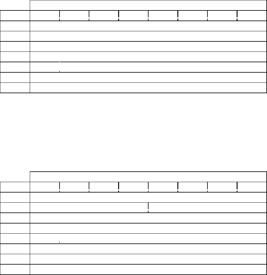
CD-ROM SCSI-2 COMMAND REFERENCE MANUAL VERSION 3.1 (OB-U0077C)
- 110 -
TABLE 2-27GMEDIA CATALOG NUMBER DATA BLOCK
Bit
Byte 76543210
4Sub Channel Data Format code (02h)
5Reserved
6Reserved
7Reserved
8MCV Reserved
9(MSB)
23 Media catalog number (UPC/Bar Code) (LSB)
TABLE 2-27HTRACK INTERNATIONAL STANDARD RECORDING CODE(ISRC) DATA
BLOCK
Bit
Byte 76543210
4Sub Channel Data Format code (03h)
5ADR Control
6Track Number
7Reserved
8TCV Reserved
9(MSB)
Track International Standard Recording Code(ISRC)
23 (LSB)
Read Sub-Channel
- 111 -
(this page has been left intentionally blank)
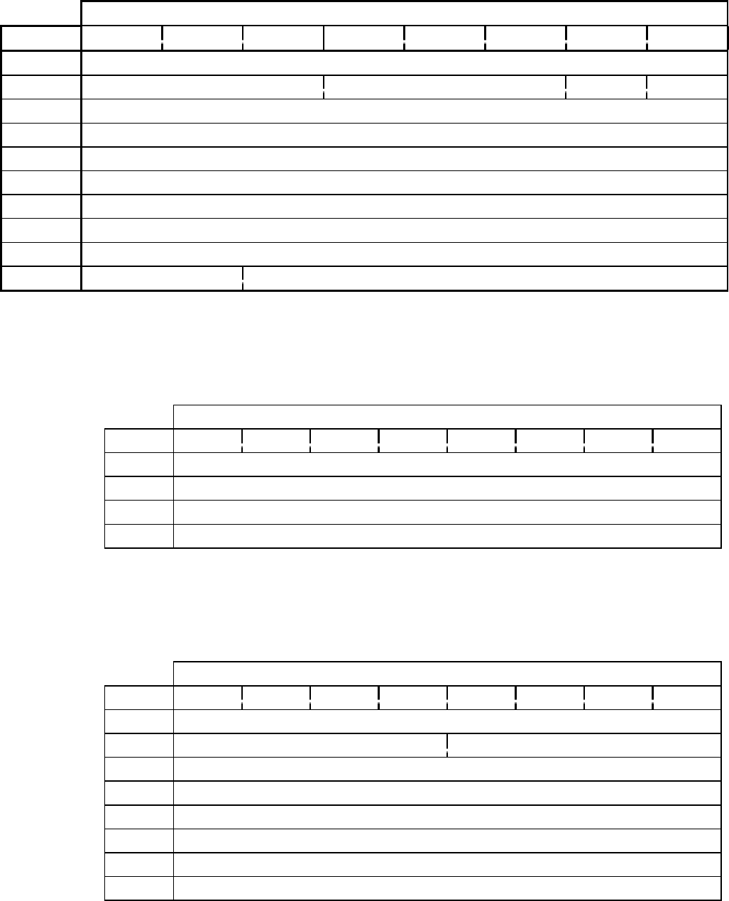
CD-ROM SCSI-2 COMMAND REFERENCE MANUAL VERSION 3.1 (OB-U0077C)
- 112 -
TABLE 2-28 READ TOC (43H)
Bit
Byte 76543210
0Operation Code (43h)
1Logical Unit No. Reserved MSF Reserve
2Reserved
3Reserved
4Reserved
5Reserved
6Start Track
7Allocation Length (MSB)
8Allocation Length (LSB)
9Format Control
TABLE 2-28ATOC DATA WITH FORMAT=00B
Bit
Byte 76543210
0TOC Data Length (MSB)
1TOC Data Length (LSB)
2First Track Number
3Last Track Number
TABLE 2-28BTRACK DESCRIPTORS
Bit
Byte 76543210
0Reserved
1ADR Control
2Track Number
3Reserved
4Absolute CD-ROM Address (MSB)
5Absolute CD-ROM Address
6Absolute CD-ROM Address
7Absolute CD-ROM Address (LSB)
Read TOC
- 113 -
2.28 Read TOC (43h)
Operation Code is (43h).
The READ TOC command requests the target transfers data from the table of contents to the
initiator.
This command has been modified from the SCSI-2 READ TOC command with the addition of
the Format field to support multi-session discs.
Format field Definition
00b Same as SCSI-2. The Start Track Field specifies the starting track number
for which the data will be returned. For multi-session discs, this command
will return the TOC data for all sessions.
01b This format returns the first session number, last session number and the
starting address of the last session. The Start Track field is reserved and
should be set to zero.
10b All Sub-Channel Q code information.(DRM-602X only)
11b Reserved.
The Start Track field specifies the starting track number for which the data shall be returned. If
this value is zero, the table of contents data shall begin with the first track on the medium. The
data is returned in contiguous ascending track number order.
If the Start Track field is not valid for the currently installed medium, the command shall be
terminated with Check Condition status. The sense key shall be set to ILLEGAL REQUEST and
the additional sense code set to INVALID FIELD IN CDB.
IMPLEMENTORS NOTE: The maximum TOC data length possible on currently available CD-
ROM media is 804 bytes, or 100 TOC track descriptors.
The TOC data block contains a four byte header followed by zero or more TOC track descriptors.
The TOC data length specifies the length in bytes of the following TOC data that is available to
be transferred during the DATA IN phase. The TOC data length value does not include the TOC
data length field itself.
The first track number field indicates the first track number in the table of contents. The last
track number field indicates the last track number in the table of contents before the lead-out
track number.
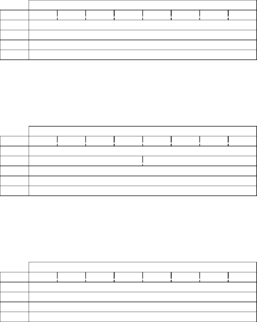
CD-ROM SCSI-2 COMMAND REFERENCE MANUAL VERSION 3.1 (OB-U0077C)
- 114 -
TABLE 2-28C TOC DATA WITH FORMAT=01B
Bit
Byte 76543210
0TOC Data Length (MSB)
1TOC Data Length (LSB)
2First Session Number
3Last Session Number
TABLE 2-28DTRACK DESCRIPTORS
Bit
Byte 76543210
0Reserved
1ADR Control
2First Track Number in Last Session
3Reserved
4 ~ 7Absolute CD-ROM Address of the First Track in the Last Session
TABLE 2-28ETOC DATA WITH FORMAT=10B (DRM-602X ONLY)
Bit
Byte 76543210
0TOC Data Length (MSB)
1TOC Data Length (LSB)
2First Session Number
3Last Session Number
Read TOC
- 115 -
IMPLEMENTORS NOTE:
The first track number is not required to be one. A disc may start at any valid track
number. The track numbers between the first track number and the last track number are
required to be in contiguous ascending order, except for the lead-out track.
The ADR field gives the type of information encoded in the Q sub-channel of the block where
this TOC entry was found. The control field indicates the attributes of the track.
The track number field indicates the track number for which the data in the TOC track descriptor
is valid. A track number of 0AAh indicates the track descriptor is for the start of the lead-out
area.
The absolute CD-ROM address contains the address of the first block with user information for
that track number as read from the table of contents. An MSF bit of zero indicates that the
absolute CD-ROM address field contains a logical block address. An MSF bit of one indicates
the absolute CD-ROM address field contains an MSF address.
IMPLEMENTORS NOTE:
The starting logical block address value recovered from the TOC has a tolerance of zero for
data tracks and plus or minus 75 CD sectors for audio tracks. This tolerance is multiplied
by a factor dependent of the logical block length.

CD-ROM SCSI-2 COMMAND REFERENCE MANUAL VERSION 3.1 (OB-U0077C)
- 116 -
TABLE 2-28FTRACK DESCRIPTORS
Bit
Byte 76543210
0Reserved
1ADR Control
2Byte1 or TNO
3Byte2 or Point
4Byte3 or Min
5Byte4 or Sec
6Byte5 or Frame
7Byte6 or Zero
8Byte7 or Pmin
9Byte8 or Psec
10 Byte9 or PFrame
Read TOC
- 117 -
(this page has been left intentionally blank)
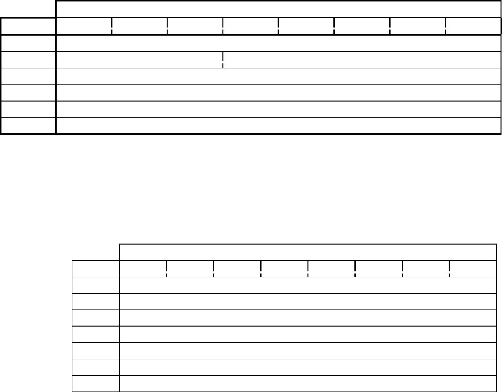
CD-ROM SCSI-2 COMMAND REFERENCE MANUAL VERSION 3.1 (OB-U0077C)
- 118 -
TABLE 2-29 RECEIVE DIAGNOSTIC RESULTS (1CH)
Bit
Byte 76543210
0Operation Code (1Ch)
1Logical Unit No. Reserved
2Reserved
3Allocation length (MSB)
4Allocation length (LSB)
5Reserved
TABLE 2-29A DIAGNOSTIC RESULTS DATA FORMAT
Bit
Byte 76543210
0Reserved
1Parameter Length (06h)
2ROM Diagnostic
3RAM Diagnostic
4Data Buffer Diagnostic
5Reserved
6Reserved
Read Diagnostic Results
- 119 -
2.29 Read Diagnostic Results (1Ch)
Operation code is (1Ch).
This command requests the drive to return the results of the power-on self test.
The Diagnostic Results data consists of 8-byte parameters as shown in Table 2-28B on the
opposite page.
Parameter Length
The number of bytes of the RECEIVE DIAGNOSTIC parameter excluding itself. This is
fixed to 06h.
ROM Diagnostic
Bit 0 = 1, failure of the SCSI controller ROM.
Bit 1 = 1, failure of the drive controller ROM.
RAM Diagnostic
Bit 0 = 1, failure of the SCSI controller RAM.
Bit 1 = 1, failure of the drive controller RAM.
Data Buffer Diagnostic
Bit 0 = 1, failure of the SCSI controller data buffer.
Bit 1 = 1, failure of the drive controller data buffer.
Bit 2 = 1, failure of the ECC RAM in the drive controller.
Interface Diagnostic
Bit 0 = 1, interface failure between the SCSI controller and the drive controller.
Bit 1 = 1, interface failure between the drive controller and the mechanism.

CD-ROM SCSI-2 COMMAND REFERENCE MANUAL VERSION 3.1 (OB-U0077C)
- 120 -
TABLE 2-30 RELEASE (17H)
Bit
Byte 76543210
0Operation Code (17h)
1Logical Unit Number 3rdPty 3rd Party device ID Ext (0)
2Reservation ID : 00h
3Reserved
4Reserved
5Reserved
Release
- 121 -
2.30 Release (17h)
Operation Code is (17h).
3rdPty
Set to one if the initiator requests third-party reservation.
3rd Party device ID
The SCSI ID of another initiator for which the logical unit shall be reserved.
Ext. (Extent)
Not supported. This bit must be 0.
Reservation ID
Not supported. This byte must be 00h.
This command is used by the reserving initiator to release the previous reservation of the logical
unit. If an initiator attempts to release a reservation that is not currently active, no error is
generated; the drive returns a GOOD status.
When the 3rd Party bit is 1, the 3rd-Party Device ID must be the same ID reserved by the
original initiator.
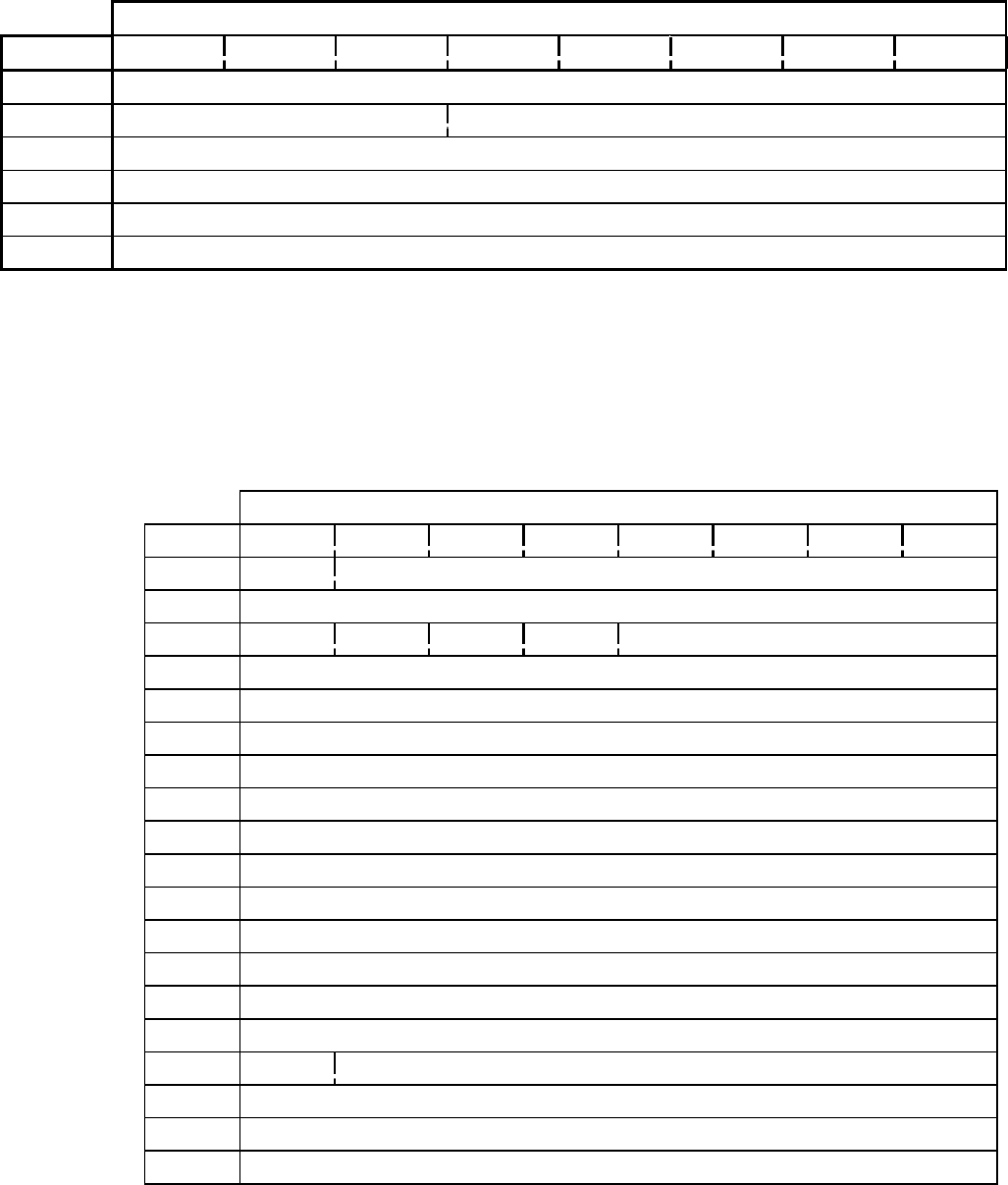
CD-ROM SCSI-2 COMMAND REFERENCE MANUAL VERSION 3.1 (OB-U0077C)
- 122 -
TABLE 2-31 REQUEST SENSE (03H)
Bit
Byte 76543210
0Operation Code (03h)
1Logical Unit Number Reserved
2Reserved
3Reserved
4Allocation Length (12h)
5Reserved
TABLE 2-31AEXTENDED SENSE DATA FORMAT
Bit
Byte 76543210
0Valid Error code (70h / 71h)
1Segment number (00h)
2FileMk EOM ILI Reserve Sense Key
3Information byte (MSB)
4Information byte
5Information byte
6Information byte (LSB)
7Additional Sense Data Length
8Command-Specific Information (MSB)
9Command-Specific Information
10 Command-Specific Information
11 Command-Specific Information (LSB)
12 Additional Sense Codes
13 Additional Sense Code Qualifier
14 Field Replaceable Unit Code
15 SKSV Sense-Key Specific (MSB)
16 Sense-Key Specific
17 Sense-Key Specific (LSB)
18 ~ N Additional Sense Bytes
Request Sense
- 123 -
2.31 Request Sense (03h)
Operation Code is (03h).
The REQUEST SENSE command requests the drive to transfer extended sense data to the
initiator. The drive supports the first 18 bytes of the extended sense data format. The drive will
transfer Allocation Length bytes or 18 bytes, whichever is smaller.
Valid
A valid bit of zero indicates that the information field is not as defined in the SCSI-2
standard. A valid bit of one indicates the information field contains valid information as
defined in the SCSI-2 specifications.
FileMk (File mark) if one indicates that the current command has read a file mark.
EOM (End of Medium) if one indicates that an end-of-medium condition exists.
ILI (Incorrect Length Indicator)
An incorrect length indicator bit set to one indicates that the requested logical block length
did not match the logical block length of the data on the medium.
Sense Key
Provides generic categories in which error and exception conditions can be reported. Table
2-31B lists the supported sense keys.
ASC / ASCQ (Additional Sense Codes)/(Additional Sense Code Qualifier)
Additional sense codes and additional sense code qualifier provides further detail
describing the sense key. These codes are listed in Table 2-31C.
Additional Sense Length
Indicates the number of additional sense bytes to follow. If the allocation length of the
command descriptor block is to small to transfer all of the additional sense bytes, the
additional sense length is not adjusted to reflect the truncation.
Command Specific Info
The field contains information that depends on the command which was executed. Further
definition for this field is contained within the command description.
SKSV
(Sense Key Specific Valid) The sense-key specific field is defined when the sense-key
specific valid (SKSV) bit is one. A SKSV value of zero indicates that this field is not
defined.

CD-ROM SCSI-2 COMMAND REFERENCE MANUAL VERSION 3.1 (OB-U0077C)
- 124 -
TABLE 2-31BSUPPORTED SENSE KEYS
Sense Key Name Comments
0h no sense There is no specific sense key information to be reported for
the designated logical unit.
1h recovered error The last command completed successfully with some
recovery action performed by the target.
2h not ready The logical unit addressed can not be accessed.
3h medium error Command terminated, unrecovered error, probably caused by
a flaw in the medium or an error in the recorded data.
4h hardware error The target detected a non-recoverable hardware failure while
performing the command or during a self-test.
5h illegal request An illegal parameter in the command descriptor block or in
the additional parameters supplied as data for commands.
6h unit attention Removable medium changed or target was reset.
7h data protect Execution of a read or write to medium command was
attempted on a protected block.
8h blank check Write-once device encountered blank medium or format
defined end of data indication while reading.
Bh aborted command Target aborted command.
Others --- not supported

Request Sense
- 125 -
TABLE 2-31CSUPPORTED ADDITIONAL SENSE CODES AND ADDITIONAL SENSE CODE
QUALIFIERS
ASC ASCQ DESCRIPTION
00 00 no additional sense information
00 06 I/O process terminated
00 11 audio play operation in progress
00 12 audio play operation pause
00 13 audio play operation successfully completed
00 14 audio play operation stopped due to error
00 15 no current audio status to return
02 00 no seek complete
04 00 logical unit not ready, cause not reportable
04 01 logical unit is in process of becoming ready
04 02 logical unit not ready, initializing command required
04 03 logical unit not ready, manual intervention required
05 00 logical unit does not respond to selection
06 00 no reference position found
07 00 multiple peripheral devices selected
08 00 logical unit communication failure
08 01 logical unit communication time out
08 02 logical unit communication parity error
09 00 track following error
09 01 tracking servo error
09 02 focus servo failure
09 03 spindle servo failure
0A 00 error log overflow
11 00 unrecovered read error
11 05 L-EC uncorrectable error
11 06 CIRC unrecovered error
14 00 recorded entity not found
14 01 record not found
15 00 random positioning error
15 01 mechanical positioning error
15 02 positioning error detected by read of medium
17 00 recovered data with no error correction applied
17 01 recovered data with retries
17 02 recovered data with positive head offset
17 03 recovered data with negative head offset
17 04 recovered data with retries and/or CIRC applied
17 05 recovered data using previous sector ID
18 00 recovered data error correction applied
18 01 recovered data error correction and retries applied
18 02 recovered data - data auto - reallocated
18 03 recovered data with CIRC
18 04 recovered data with L-EC
18 05 recovered data - recommend reassignment
1A 00 parameter list length error
1B 00 synchronous data transfer error
20 00 invalid command operation code
CONTINUED

CD-ROM SCSI-2 COMMAND REFERENCE MANUAL VERSION 3.1 (OB-U0077C)
- 126 -
Table 2-31CSupported additional sense codes and additional sense code qualifiers (continued)
ASC ASCQ DESCRIPTION
21 00 logical block address out of range
24 00 invalid field in CDB
25 00 logical unit not supported
26 00 invalid field in parameter list
26 01 parameter not supported
26 02 parameter value invalid
26 03 threshold parameters not supported
28 00 not ready to ready transition (medium may have changed)
29 00 power on, reset or bus device reset occurred
2A 00 parameters changed
2A 01 mode parameters changed
2A 02 log parameters changed
2B 00 copy can not execute since host can not disconnect
2C 00 command sequence error
2F 00 commands cleared by another initiator
30 00 incompatible medium installed
30 01 can not read medium - unknown format
30 02 can not read medium - incompatible format
37 00 rounded parameter
39 00 saving parameters not supported
3A 00 medium not present
3D 00 invalid bits in identify message
3E 00 logical unit has not self-configured yet
3F 00 target operating conditions have changed
3F 01 micro code has been changed
3F 02 changed operation definition
3F 03 inquiry data has changed
40 00 diagnostic failure on component NN (80h-FFh)
43 00 message error
44 00 internal target failure
45 00 select or reselect failure
46 00 unsuccessful soft reset
47 00 SCSI parity error
48 00 initiator detected error message received
49 00 invalid message error
4A 00 command phase error
4B 00 data phase error
4C 00 logical unit failed self configuration
4E 00 overlapped commands attempted
53 00 media load or eject failed
53 02 medium removal prevented
57 00 unable to recover TOC
5A 00 operation request or state change input (unspecified)
5A 01 operator medium removal request
5B 00 log exception
5B 01 threshold condition met
5B 02 log counter at maximum
5B 03 log list codes exhausted
63 00 end of user area encountered on this track
64 00 illegal mode for this track
Request Sense
- 127 -
(this page has been left intentionally blank)

CD-ROM SCSI-2 COMMAND REFERENCE MANUAL VERSION 3.1 (OB-U0077C)
- 128 -
TABLE 2-32 RESERVE (16H)
Bit
Byte 76543210
0Operation Code (16h)
1Logical Unit No. 3rdPty 3rd Party Device ID Ext (0)
2Reservation ID (00h)
3Extent List length (00h)
4Extent List length (00h)
5Reserved
Reserve
- 129 -
2.32 Reserve (16h)
Operation Code is (16h).
3rdPty
Set to one if the initiator requests third-party reservation.
3rd Party Device ID
The SCSI ID of another initiator for which the logical unit shall be reserved.
Ext. (Extent) is not supported. This bit must be 0.
Reservation ID is not supported. This byte must be 00h.
Extent List length is not supported. These bytes must be 00h.
The initiator uses this command to exclusively reserve the specified logical unit. Area
reservations using the Extent bit are not supported. If the 3rd Party bit is 1, the logical unit is
reserved for another SCSI device specified by the 3rd Party Device ID. The initiator can change
the reservation by issuing a new RESERVE UNIT command to the reserved unit. In this case,
the previous reservation is released when the new reservation is received.
The reserved condition is maintained until the original initiator issues another valid RESERVE
UNIT command or a RELEASE UNIT command; when a BUS DEVICE RESET message is
issued by any initiator; or when a hardware reset condition occurs. In the latter two reset cases, a
UNIT ATTENTION condition is reported for the next SCSI command.
Any reservation request by an initiator for a logical unit that has been reserved by another
initiator is rejected, and a RESERVATION CONFLICT status is returned.
If the 3rd Party bit is 1, the logical unit is reserved for the SCSI device indicated by the 3rd-
Party Device ID. The reserved state is maintained as described previously. Any release request
is ignored, and a GOOD status is returned if it comes from an initiator other than the one that
issued the reservation command.

CD-ROM SCSI-2 COMMAND REFERENCE MANUAL VERSION 3.1 (OB-U0077C)
- 130 -
TABLE 2-33 REZERO UNIT (01H)
Bit
Byte 76543210
0Operation Code (01h)
1Logical Unit No. Reserved
2Reserved
3Reserved
4Reserved
5Reserved
Rezero Unit
- 131 -
2.33 Rezero Unit (01h)
Operation Code is (01h).
The drive loads the specified logical unit (if necessary), spins up the disc (if stopped), moves the
head to the start track of the disc, and holds it there until an inactivity time-out occurs. If the
initiator requests a disconnect, the drive disconnects from it during load and seek operations.
This command does not affect modes specified by the MODE SELECT command.

CD-ROM SCSI-2 COMMAND REFERENCE MANUAL VERSION 3.1 (OB-U0077C)
- 132 -
TABLE 2-34 SEEK(6) (0BH)
Bit
Byte 76543210
0Operation Code (0Bh)
1Logical Unit No. Logical Block Address (MSB)
2Logical Block Address
3Logical Block Address (LSB)
4Reserved
5Reserved
Seek(6)
- 133 -
2.34 Seek(6)
Operation Code is (0Bh).
The drive seeks to the specified logical block address and then holds at that track until an
inactivity time-out occurs.

CD-ROM SCSI-2 COMMAND REFERENCE MANUAL VERSION 3.1 (OB-U0077C)
- 134 -
TABLE 2-35 SEEK(10) (2BH)
Bit
Byte 76543210
0Operation Code (2Bh)
1Logical Unit No. Reserved 0
2Logical Block Address (MSB)
3Logical Block Address
4Logical Block Address
5Logical Block Address (LSB)
6Reserved
7Reserved
8Reserved
9Reserved
Seek(10)
- 135 -
2.35 Seek(10) (2Bh)
Operation code is (2Bh).
The drive seeks to the specified logical block address and then holds at that track until an
inactivity time-out occurs.
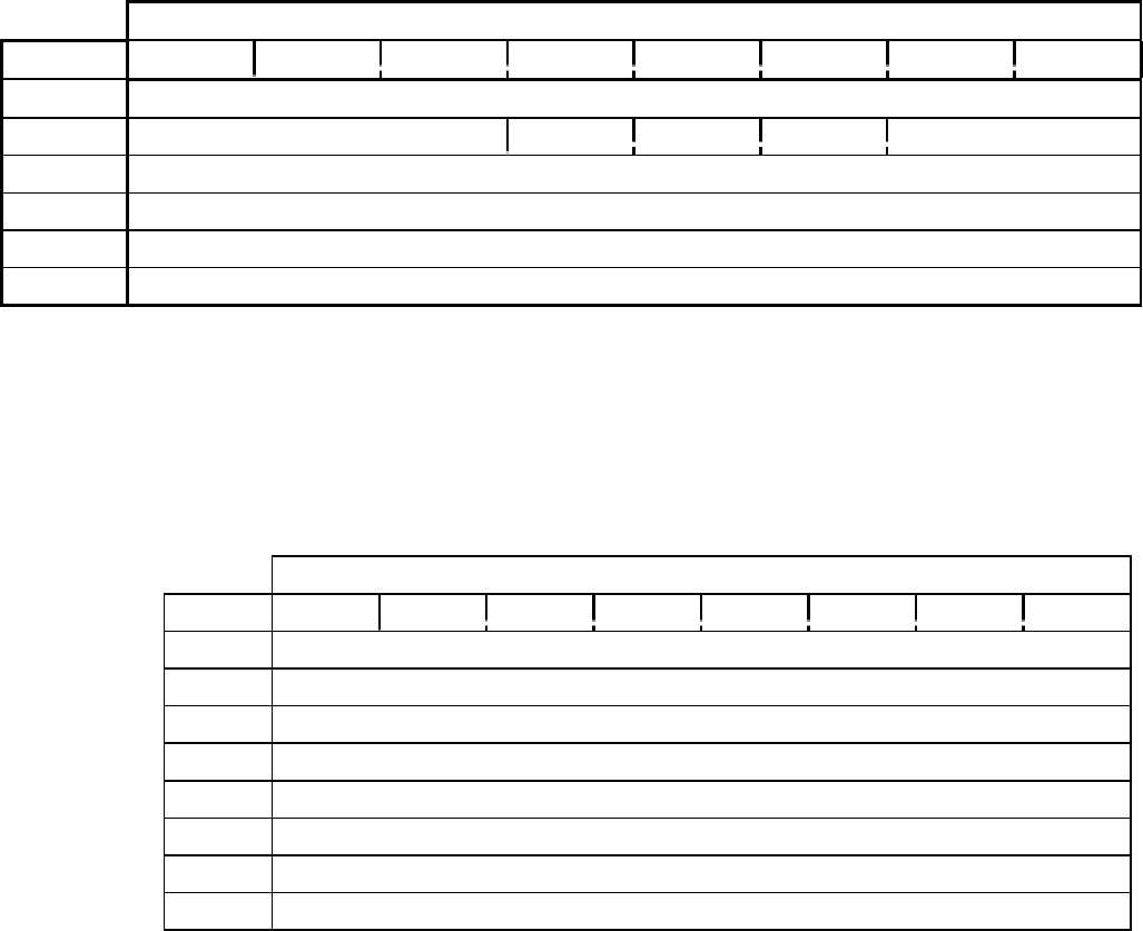
CD-ROM SCSI-2 COMMAND REFERENCE MANUAL VERSION 3.1 (OB-U0077C)
- 136 -
TABLE 2-36 SEND DIAGNOSTIC (1DH)
Bit
Byte 76543210
0Operation Code (1Dh)
1Logical Unit No. PF Res Self Reserved
2Reserved
3Allocation length (MSB)
4Allocation length (LSB)
5Reserved
TABLE 2-36ASEND DIAGNOSTIC DATA FORMAT
Bit
Byte 76543210
0Reserved
1Parameter Length (06h)
2ROM Diagnostic
3RAM Diagnostic
4Data Buffer Diagnostic
5Interface Diagnostic
6Reserved
7Reserved
Send Diagnostic
- 137 -
2.36 Send Diagnostic (1Dh)
Operation code is (1Dh).
PF must be 0.
Self (Self-Test bit) if “1” (ONE), default self-test is executed. If “0” (ZERO), send diagnostic
data issued.
Allocation length set to 0 when Self bit is one. When Self bit is 0, set to 8h.
This command reports the results of the drive's power-on self test (when the self bit is one). If
test is successful, GOOD status is returned. If a problem was detected, Check Condition with
sense key HARDWARE ERROR is returned. Use RECEIVE DIAGNOSTIC RESULTS to
determine the problem area.
If self bit is zero, target returns GOOD status after received specified CDB and parameter list.
A Result of the test will be returned by the RECEIVE DIAGNOSTIC RESULT command.
The Send Diagnostic data consists of 8-byte parameters as shown in the following table:
Parameter Length is the number of bytes of the SEND DIAGNOSTIC parameter excluding
itself. This is fixed to 06h.
ROM Diagnostic
Bit 0 = 1, test the SCSI controller ROM.
Bit 1 = 1, test the drive controller ROM.
RAM Diagnostic
Bit 0 = 1, test the SCSI controller RAM.
Bit 1 = 1, test the drive controller RAM.
Data Buffer Diagnostic
Bit 0 = 1, test the SCSI controller data buffer.
Bit 1 = 1, test the drive controller data buffer.
Bit 2 = 1, test the ECC RAM in the drive controller.
Interface Diagnostic
Bit 0 = 1, test interface between the SCSI controller and the drive controller.
Bit 1 = 1, test interface between the drive controller and the mechanism.

CD-ROM SCSI-2 COMMAND REFERENCE MANUAL VERSION 3.1 (OB-U0077C)
- 138 -
TABLE 2-37 SET CD-ROM SPEED(1) (DAH)
Bit
Byte 76543210
0Operation Code (DAh)
1Reserved
2Speed
3Reserved
4Reserved
5Reserved
6Reserved
7Reserved
8Reserved
9Reserved
10 Reserved
11 Reserved

Set CD-ROM Speed(1)
- 139 -
2.37 Set CD-ROM Speed(1) (DAh)
Operation code is (DAh).
The Set CD-ROM Speed command provides a means for initiator to set the spindle motor speed.
Speed Field Value Description
00h :Normal Speed
01h :2x Speed
03h :4x Speed
FFh :Maximum Speed
Other Value :Any other value not specified will set the drive to maximum Speed
Drive Differences:
DRM-602x The DRM-602x does not support 4x speed. A speed setting value of 03h
will not cause an error, but set the drive to 2x speed.
DRM-624x, DRM-604x, DR-U124x, DR-UA124X, and DR-D504X
These drives do not support 2x Speed. A speed setting value of 01h will not cause an error.
However, the drive will automatically be set to 4x speed.

CD-ROM SCSI-2 COMMAND REFERENCE MANUAL VERSION 3.1 (OB-U0077C)
- 140 -
TABLE 2-38 SET CD-ROM SPEED(2) (BBH)
Bit
Byte 76543210
0Operation code (BBh)
1Reserved
2(MSB) Drive Speed in Kbytes/Second
3 (LSB)
4Reserved
5Reserved
6Reserved
7Reserved
8Reserved
9Reserved
10 Reserved
11 Reserved
Set CD-ROM Speed(2)
- 141 -
2.38 Set CD-ROM Speed(2) (BBh)
The Drive Speed parameter contains the requested Data Rate the drive should use. The drive may
choose to select the speed specified or any slower rate. A value of FFFFh will set the Drive
Speed to the Maximum supported. Requesting a speed faster than the drive supports will not
generate an error. The actual maximum speed supported is returned in the Capabilities Mode
Sense page.

CD-ROM SCSI-2 COMMAND REFERENCE MANUAL VERSION 3.1 (OB-U0077C)
- 142 -
TABLE 2-39 START/STOP UNIT (1BH)
Bit
Byte 76543210
0Operation Code (1Bh)
1Logical Unit No. Reserved Immed
2Reserved
3Reserved
4Reserved LoEj Start
5Reserved
Start/Stop Unit
- 143 -
2.39 Start/Stop Unit (1Bh)
Operation code is (1Bh).
Immed (Immediate)
When the immediate bit is 1, status is returned before executing the command . When it is
0, status is returned after the operation is completed.
LoEj (Load Eject)
When LoEj is 1 and Start is 0, the drive ejects the magazine.
Start
When Start is 1, the disc tray is loaded, the disc is spun up, and the laser and servo system
are turned on. When it is 0, the disk is spun down.

CD-ROM SCSI-2 COMMAND REFERENCE MANUAL VERSION 3.1 (OB-U0077C)
- 144 -
TABLE 2-40 STOP PLAY/SCAN (4EH)
Bit
Byte/Bit 7 6 5 4 3 2 1 0
0Operation code (4Eh)
1Reserved
2Reserved
3Reserved
4Reserved
5Reserved
6Reserved
7Reserved
8Reserved
9Reserved
10 Reserved
11 Reserved
Stop Play/Scan
- 145 -
2.40 Stop Play/Scan (4Eh)
The STOP PLAY/SCAN CD-ROM Command stops playback of CD-ROM audio commands.

CD-ROM SCSI-2 COMMAND REFERENCE MANUAL VERSION 3.1 (OB-U0077C)
- 146 -
TABLE 2-41 TEST UNIT READY (00H)
Bit
Byte 76543210
0Operation Code (00h)
1Logical Unit No. Reserved
2Reserved
3Reserved
4Reserved
5Reserved
Test Unit Ready
- 147 -
2.41 Test Unit Ready (00h)
Operation Code is (00h).
The TEST UNIT READY command checks that a cartridge is loaded and that the drive is ready
to operate. "Ready" has different meanings depending on whether the drive has accessed a
logical unit by loading the disc tray:
Before access to logical unit : Magazine is inserted and the drive is ready to read.
After an access to logical unit: A disc is in the specified logical unit (or tray) and is ready to
be accessed.
The TEST UNIT READY command does not load the logical unit's tray. (See REZERO UNIT)
See 1.3 for Disc Status Information.
A Not Ready condition can occur when:
(1) No magazine is inserted in the drive.
(2) The magazine cannot be inserted or ejected.
(3) The drive cannot read TOC information on a disc.
(4) There is no disc present.

CD-ROM SCSI-2 COMMAND REFERENCE MANUAL VERSION 3.1 (OB-U0077C)
- 148 -
TABLE 2-42 VERIFY(10) (2FH)
Bit
Byte 76543210
0Operation Code (2Fh)
1Logical Unit No. Reserved Blkvry Bytchk RelAdr
2Logical block address (MSB)
3Logical block address
4Logical block address
5Logical block address (LSB)
6Reserved
7Verification length (MSB)
8Verification length (LSB)
9Reserved
Verify(10)
- 149 -
2.42 Verify(10) (2Fh)
Operation code is (2Fh).
Logical Block Address is the address at which the verify operation shall begin.
Verification Length is the number of logical blocks to be verified.
This command requests the drive to check the specified blocks on the disc based upon the error
recovery parameter setting (see MODE SELECT command). No data transfer on the SCSI bus
occurs.
NOTE: The BlkVry (Blank verify), BytChk (Byte Check) and RelAdr bits in byte 1 are not
supported, and should be set to 0.

CD-ROM SCSI-2 COMMAND REFERENCE MANUAL VERSION 3.1 (OB-U0077C)
- 150 -
TABLE 2-43 VERIFY(12) (AFH)
Bit
Byte 76543210
0Operation Code (AFh)
1Logical Unit No. Reserved 000
2Logical block address (MSB)
3Logical block address
4Logical block address
5Logical block address (LSB)
6Verification Length (MSB)
7Verification Length
8Verification Length
9Verification Length (LSB)
10 Reserved
11 Reserved
Verify(12)
- 151 -
2.43 Verify(12) (AFh)
Operation code is (AFh).
See VERIFY(10) for complete description of this command.

CD-ROM SCSI-2 COMMAND REFERENCE MANUAL VERSION 3.1 (OB-U0077C)
- 152 -
TABLE 2-44 WRITE BUFFER (3BH)
Bit
Byte 76543210
0Operation Code (3Bh)
1Logical Unit No. Reserved Mode
2Buffer ID (00h)
3Buffer offset (MSB)
4Buffer offset
5Buffer offset (LSB)
6Transfer length (MSB)
7Transfer length
8Transfer length (LSB)
9Reserved
TABLE 2-38AWRITE BUFFER HEADER
Bit
Byte 76543210
0Reserved
1Reserved
2Reserved
3Reserved
Write Buffer
- 153 -
2.44 Write Buffer (3Bh)
Operation Code is (3Bh).
Mode specifies meaning of the Buffer Offset field.
Buffer ID is not supported. This byte must be 00h.
Buffer Offset is the byte offset in the buffer where the data shall be stored. This must be 0
through 15.
Transfer Length is the number of bytes to be transferred in the DATA OUT phase. This must
be the data length to be sent plus 4 bytes (header size).
This command is to be used with the READ BUFFER command to test the reliability of the
command buffer memory in the drive, and of the SCSI bus. The drive does not access any discs.
Mode Definition
00b Header, data, and buffer offset are 0s.
01b Buffer offset indicates the offset of the buffer at which data are to be stored.
10b Reserved
11b Reserved
The transfer length must include the 4-byte header, therefore, the actual data length to be stored
is the transfer length minus 4 bytes. As the buffer length of the drive is 16 bytes, the maximum
number of bytes that can be specified for Buffer Offset is 15, and the maximum for Transfer
Length is 20.
If Transfer length is larger than 20, a Check Condition is returned with the sense key "ILLEGAL
REQUEST." Check Condition will also be returned if the Buffer Offset + Transfer Length is
larger than 20.
If Buffer Offset is not 0 when Mode is 00h, Check Condition is returned.
Refer to Table 2-38A on the opposite page for the 4-byte header of 00h's must be sent preceding
the test data.

CD-ROM SCSI-2 COMMAND REFERENCE MANUAL VERSION 3.1 (OB-U0077C)
- 154 -
TABLE 2-45 WRITE CDP (E3H)
Bit
Byte 76543210
0Operation Code (E3h)
1Logical Unit No. Reserved
2Reserved
3Reserved
4Reserved
5Reserved
6Reserved
7Reserved
8Transfer length (MSB) (00h)
9Transfer length (LSB) : <= 14h
10 Reserved
11 Reserved
Write CDP
- 155 -
2.45 Write CDP (E3h)
Operation Code is (E3h).
Transfer Length is the number of bytes of CDP command data to be sent.
This command sends alphanumeric Player Control commands to the drive. The drive returns the
command status after the player control command is transferred to the drive controller chip. A
GOOD status indicates only that the command was syntactically correct. The READ CDP
command must be used to determine the results of the operation.
(See Appendices A and B for details on audio functions.)
The Player Control command data can contain up to 21 characters including a Carriage Return
(0Dh). If Transfer Length is larger than 21, Check Condition is returned with sense key
ILLEGAL REQUEST and sense code 24h, "Invalid Command Block Other Than 20 or 21".
IMPORTANT: THE COMMAND STRING MUST BE TERMINATED WITH A CARRIAGE
RETURN
Data after a Carriage Return is ignored. When there is no Carriage Return, Check Condition is
returned with sense key ILLEGAL REQUEST, sense code "Error in Parameter List" (26h).
When media change is prohibited by the PREVENT/ALLOW MEDIA REMOVAL command,
the magazine eject command "Z0" is ignored. When the command string consists of multiple
request commands (such as "?Z"), only the status of the first command is returned by the READ
CDP command.

CD-ROM SCSI-2 COMMAND REFERENCE MANUAL VERSION 3.1 (OB-U0077C)
- 156 -
TABLE 2-46 READ CD-DA (D8H)
Bit
Byte 76543210
0Operation Code (D8h)
1Logical Unit Number Reserved
2(MSB)
3
4Starting Logical Block Address
5 (LSB)
6Reserved
7(MSB)
8Transfer length
9 (LSB)
10 Sub Code
11 Reserved

Read CD-DA
- 157 -
2.46 Read CD-DA (D8h)
IMPORTANT: This command applies only to models DRM-602X, DRM-624X, and the DR-U
Series drives.
Operation Code is (D8h).
The READ CD-DA command requests that the drive transfer CD-DA data and/or Sub Code
data.
The Starting Logical Block Address specifies the block where the READ operation begins.
The definition of the starting logical block address is as follows:
Starting Logical Block Address = (M-Ms) * 60 * 75 + (S-Ss) * 75 + (F-Fs)
(M, S, F) = absolute MSF address of the requested starting logical block
(Ms, Ss, Fs) = absolute MSF address of the first block of the first track
Sub Code Field:
Sub Code Field CD-DA block length Description
00h 2352 bytes CD-DA data with no Sub Code
01h 2368 bytes CD-DA data with Sub Q Code
02h 2448 bytes CD-DA data with all Sub Code
03h 96 bytes All Sub Code only
04 ~ FFh Reserved
If the Sub Code field is set to 00h, the drive returns the CD-DA data without Sub Code data.
(Each block consists of 2352 bytes of digital audio data without any Sub Code data.)
If the Sub Code field is set to 01h, the drive returns the CD-DA data with Sub Q data. Each
block consists of 2368 bytes which includes 2352 bytes of digital audio data, 10 bytes of Sub Q
data and 6 bytes of zeros. Note: 16 bits of CRC for the Sub Q data are not transferred.
If the Sub Code field is set to 02h, the drive returns the CD-DA data with all Sub Code data.
(Each block consists of 2448 bytes which includes 2358 bytes of digital audio data and 96 bytes
of Sub Code data.)
If the Sub Code field is set to 03h, the drive returns 96 bytes of all Sub Code data only.
The Transfer Length specifies the number of contiguous CD-DA data blocks to be transferred.
CD-ROM SCSI-2 COMMAND REFERENCE MANUAL VERSION 3.1 (OB-U0077C)
- 158 -
NOTES:
1) The CD-DA block lengths are totally irrelevant to the logical block length set by the
Mode Select(6) command. This command would not change the block length field in the
MODE SELECT command.
2) While the SCSI buffer is being filled, the drive is able to prepare with no overlap or
missing data in response to the consecutive commands which read contiguous CD-DA
blocks.
When the host cannot read the data quick enough and the buffer is full, the drive will stop
refilling the buffer. The host is still capable of reading all CD-DA data in the SCSI buffer
with consecutive read commands without overlap or missing bits at the block boundary.
Once the buffer is full, the first read command to read the next sequential CD-DA
block(e.g. X+1) after the last CD-DA block(e.g. X) in the buffer will cause a Check
Condition with a sense key of 05h and an additional sense code of BAh(buffer overflow).
There is no check condition for a read command which does not request block X+1(e.g. a
Read(X+2, 1) command). In addition, a second read command which requests block X+1
will not get a check condition.
For Example (In case that the last CD-DA block stored in the buffer is X):
In a Read(X-2, 5) command to read block X-2 to X+2, the drive returns three CD- DA data
blocks and then a check condition. The drive returns the block X+1 address in the
information bytes(byte 3 to 6) of a subsequent Request Sense command. There are no
overlap of missing bits for blocks X-2, X-1 and X. Block X and X+1 are not transferred.
That is; in case of reading CD-DA blocks, the drive has only rough access. Once the data
stream from the media has been stopped, it is unable to have such pin-point access as in
CD-ROM blocks. (Each CD-ROM block always includes the CD-ROM Header that
provides the pin-point access.)
3) The volume level control is not performed on any SCSI CD-DA data. Analog audio
output is not performed while SCSI CD-DA data is in transaction, either.
4) The drive transfers data to the host at the burst transfer rate for the entire block of data.
The drive's firmware overhead should only occur at a block boundary. Upon completion of
the read operation, the drive enters the Hold Track state during inactive time.
Read CD-DA
- 159 -
(this page has been left intentionally blank)

CD-ROM SCSI-2 COMMAND REFERENCE MANUAL VERSION 3.1 (OB-U0077C)
- 160 -
TABLE 2-47 READ CD-DA MSF (D9H)
Bit
Byte 76543210
0Operation Code (D9h)
1Logical Unit No. Reserved
2Reserved
3Starting M Field
4Starting S Field
5Starting F Field
6Reserved
7Ending M Field
8Ending S Field
9Ending F Field
10 Sub Code
11 Reserved
Read CD-DA MSF
- 161 -
2.47 Read CD-DA MSF (D9h)
IMPORTANT: This command applies only to models DRM-602X, DRM-624X, and the DR-U
Series drives.
Operation Code is (D9h).
Starting M, S, F Fields indicates the absolute MSF address where the operation begins.
Ending M, S, F Fields indicates the absolute MSF address where the operation ends. If the
ending address is smaller than the starting address, check condition will be returned. The sense
key is set to Illegal Request (05h), the additional sense code is set to Invalid field in CDB (24h).
Sub Code Field - for details, refer to the READ CD-DA command.
The READ CD-DA MSF command requests that the drive transfer CD-DA data.
The data transfer length (bytes) is calculated as follows;
Data Transfer Length = [(Me-Ms) * 60 * 75 + (Se-Ss) * 75 + (Fe-Fs)] * CD-DA Block length
(Ms, Ss, Fs) = Starting MSF address
(Me, Se, Fe) = Ending MSF address
NOTE: The drive transfers the entire block of data to the host at SCSI bus burst transfer rate. The
drive's firmware overhead should only occur at a block boundary. Upon completion of the read
operation, the drive enters Hold Track State during inactive time.

CD-ROM SCSI-2 COMMAND REFERENCE MANUAL VERSION 3.1 (OB-U0077C)
- 162 -
TABLE 2-48 READ CD-XA (DBH)
Bit
Byte 76543210
0Operation Code (DBh)
1Logical Unit No. Reserved
2(MSB)
3Starting Address
4
5 (LSB)
6CD-XA Format
7(MSB)
8
9Transfer Length
10 (LSB)
11 Reserved

Read CD-XA
- 163 -
2.48 READ CD-XA (DBh)
IMPORTANT: This command applies only to models DRM-602X, DRM-624X, and the DR-U
Series drives.
Operation Code is (DBh).
Starting Address specifies the block where the operation begins.
Transfer Length specifies the number of contiguous CD-XA blocks to be transferred.
The READ CD-XA command requests that the drive transfer CD-XA data to the host.
The Starting Address is defined as follows.
Starting Address = M * 60 * 75 + (S-2) * 75 + F
M, S & F = the absolute MSF address of the requested starting address
CD-XA Format Field:
CD-XA Field CD-XA Block Length Description
00h 2048 bytes User data only (no sub header)
0Fh 2352 bytes All CD-XA sector data
1Fh 2646 bytes All data with 294-byte Error Flags
Other Codes Reserved
When the CD-XA Format field is set to 00h, the drive returns 2048 bytes CD-XA data in the
user data area without any Sub-header data. If the requested block is in a CD-XA Mode2/Form2
sector, only 2048 bytes user data will be returned and the remaining data will be discarded.
When the CD-XA Format field is set to 0Fh, the drive returns all 2352 bytes CD-XA sector
data.
When the CD-XA Format field is set to 1Fh, the drive returns the CD-XA data with Error Flag
data. Each block consists of 2646 bytes which includes the entire block of 2352 bytes CD-XA
data and a block of 294 bytes Error Flag data.
NOTE: The CD-XA block length is totally irrelevant to the logical block length set by Mode
Select Command.

CD-ROM SCSI-2 COMMAND REFERENCE MANUAL VERSION 3.1 (OB-U0077C)
- 164 -
TABLE 2-49 READ ALL SUBCODE (DFH)
Bit
Byte 76543210
0Operation Code (DFh)
1Logical Unit Number Reserved
2Reserved
3Reserved
4Reserved
5Reserved
6(MSB)
7
8Transfer Length
9 (LSB)
10 Reserved
11 Reserved
Read All SubCode
- 165 -
2.49 Read All SubCode (DFh)
IMPORTANT: This command applies only to models DRM-602X, DRM-624X, and the DR-U
Series drives.
Operation Code is (DFh)
Transfer Length indicates the number of contiguous sub-code frames to be transferred. Each
sub-code frame consists of 96-byte data.
Read All Subcode command directs the target to transfer real-time sub-code data (P-W) to the
initiator while the audio is being played.
The initiator must hold while the current sub-code is being retrieved from the disc.
If the Transfer Length is zero, sub-code data will not be transferred. In this case, however, it is
not considered an error.
In the event the sub-code buffer is full in the drive, the drive will stop storing sub-code data into
the buffer. However, the data in the buffer is accessible by this command.
The drive will quit the operation with a Check Condition status once the buffer overflows
or there is no more valid sub-code data in the buffer. The sense key is set to 05h and the
additional sense code is to BFh. The Check Condition for buffer overflow occurs only for the
READ ALL SUBCODE command.
If the target is not playing the audio, the drive will return a Check Condition status.
The sense key is set to 05h and the additional sense code is to 64h.
NOTE: The drive transfers an entire block of data at SCSI bus burst transfer rate. The drive's
firmware overhead only occurs at a block boundary. Upon completion of the read operation, the
drive enters the Hold Track state during the inactivity time.
Appendix A
A-I
APPENDIX A PIONEER CD-ROM DRIVES - AUDIO FUNCTIONS
The CD-ROM drives consist of two logical subsystems - a CD reader and a controller. The controller
receives SCSI commands, and sends commands to the reader for execution as needed. This allows audio
commands to be executed in the background. At times, the two subsystems may be operating
independently.
In addition to the normal audio commands, the CD-ROM drives support the Pioneer Laser Disc Player
control commands. These alphanumeric mnemonics may be sent to the drive using the vendor-unique
command WRITE CDP (Character Device Player). The WRITE READ CDP command strings are
passed through the controller directly to the reader. The controller checks the length and termination of
the command string, and, if valid, returns a GOOD status. The controller will generate a Check
Condition with a sense key of ILLEGAL REQUEST if the string is not valid. The controller then passes
the command string to the reader for execution. To receive the results of the command string, the
initiator must use the READ CDP command to get the status from the reader. The reader passes the
result data through the controller. Invalid commands or execution errors will not cause SCSI errors, but
will be reported by the READ CDP command.
Certain types of data, such as the disc TOC, are stored by the controller once they have been read from
the disc. If a disc has been accessed, a READ TOC command will not require a disc access, which could
include a disc change. Instead, the TOC data is transferred from controller memory.

Appendix B
B-I
APPENDIX B AUDIO PLAYER COMMANDS
Addressing Modes
Block MMSSFF Specifies Minutes, Seconds, and Frames.
Index I I Specifies pre-mastered indices
Time MMSS Specifies Minutes and Seconds (Frame 0)
Track TT Specifies the beginning of track TT
Player Modes
P00 Home No disc is loaded. Magazine not inserted.
P00 Home No disc is loaded. Magazine inserted.
P01 Park The disc is loaded, but not spinning.
P03 Stop
P04 Play The drive is playing audio.
P06 Pause The disc is spinning, but audio play has been paused.
The following table lists the Command Mnemonic and explanation for each player command.
CM Command Drive Action
?A Address Request Returns a 10-digit string (TTIIMMSSFF) representing Track number, Index
number, and P-code time for the current address. In Park mode, the string is
XXXXXXXXXX, at lead-in 0000000000. At lead-out, the string is
AA01000000.
?B Block Request Returns a six digit string representing the current address in MMSSFF format.
In Park mode, XXXXXX is returned. 000000 is returned when the current
address is in the lead-in area.
BK Block Mode Sets the addressing mode to Block mode. All subsequent addresses must be in
MMSSFF format.
CL Clear Clears the buffer which stores the stop marker. Will also cancel search mode or
play modes.
?G Catalog Request Returns the disc's 13 digit catalog number. If the disc does not have a catalog
number, or if no disc is loaded, the string will be all "X"s.
?I Index Request Returns a four digit string representing the track number and index number. In
Park mode, XXXX is returned. 0000 is returned when the current address is in
the lead-in area, and AA01 when in the lead-out area.

CD-ROM SCSI-2 COMMAND REFERENCE MANUAL VERSION 3.1 (OB-U0077C)
B-II
CM Command Drive Action (continued)
IX Index Mode Sets the addressing mode to Index mode. All subsequent addresses will be
interpreted as indices.
?K Disc Status Request Returns an eight character string representing the attributes of the currently
loaded disc. (N1 - N8)
N1:Disc Loaded 0: No 1: Yes X: Unknown
N2:Audio Track 0: Not Present1: Present X: Unknown
N3:Data Track 0: Not Present1: Present X: Unknown
N4:CDV 0: No 1: Yes X: Unknown
N5:CD-I 0: No 1: Yes X: Unknown
N6-8: Reserved (All X)
n KL Key Lock Enables or disables the front panel eject button. n = 0: Enabled. n = 1:
Disabled
LO Lead Out Lead Out Address
NF Scan Forward Scans forward about 15 seconds, with audio attenuated by 12 dB.
NR Scan Reverse Scans backwards about 15 seconds, with audio attenuated by 12dB.
?O Read ISRC Returns the 15 digit International Standard Recording Code for the current track.
(DRM-604X series only)
?P Mode Request Returns three digit string representing player mode: P00 - Home (No Magazine),
P01 - Park Mode, P04 - Play Mode, P06 - Pause Mode, P20 - Home Mode
(Magazine Inserted)
PA Pause Enters Pause mode at the current address.
PL Play Enters Play mode and begins audio play.
?Q TOC Request Returns TOC data as a 10 digit string (FFLLEEEEEE), where FF represents the
first track, LL represents the last track number, and EEEEEE represents the lead-
out address in MMSSFF format.
?n QTOC Request Returns TOC data for track n as an eight digit string (EEEEEETT), where
EEEEEE represents the absolute start address of the track in MMSSFF format,
and TT represents the track type. 00 means audio, 04 means data.
?R Track Request Returns a two digit string representing the current track. In Park mode, XX is
returned. 00 is returned when the current address is in the lead-in area, an AA
when in the lead-out area.
RJ Reject Stops the disc and enters Park mode.
SA Start Starts disc rotation. The drive will pause at the beginning of the first audio
track.
a SE Search Searches to address a and enters Pause mode.
a SM Stop Marker Sets a stop marker at address a. When the stop marker is reached, the drive
enters Pause mode. Stop markers are cleared by CL and RJ commands.

Appendix B
B-III
CM Command Drive Action (continued)
?T Time Request Returns a four digit string representing the current time in MMSS format. In
Park mode, XXXX is returned. 0000 is returned when the current address is in
the lead-in area.
TM Time Mode Sets the addressing mode to Time mode. All subsequent addresses must be in
MMSS format.
TR Track Mode Sets the addressing mode to Track Mode. All subsequent addresses must be in
TT format, specifying a track number.
n VL Volume Sets the audio playback level, from 0 to 255.
?X CDP Model Returns the revision of the CDP ROM Example: "P150801"
?Z Disc Query Returns a three digit number representing the currently loaded disc. If there is no
disc loaded, "XXX" will be returned.
ZO Eject Magazine Ejects the magazine.
ZR Disc Return Unloads the currently loaded logical unit (tray).
n ZS Disc Select Loads disc n (1-6). After the disc is loaded, the drive goes into Park mode.
Player Command Error Messages
Return Error Explanation
R(GOOD) The command completed successfully.
E00 Communication Error Error in command, command too long
E04 Feature not Available Unusable command, wrong mode, bad track
E06 Missing Argument A required parameter was not supplied
E11 Disc not Present No disc loaded, magazine not inserted
E12 Address Error Search address not found
E13 Focus Error Focus lost (Hardware problem)
E14 Spindle Unlocked The spindle is not locking
E16 Eject Received Front panel Eject button pressed before command finished
E90 Panic - Mechanical A non-recoverable error has occurred in a mechanical operation such
as loading.
E91 Can't Eject Magazine
E92 Can't Load
E96 Can't Start Drive was unable to spin-up the disc
E99 Panic A non-recoverable operational error has occurred.

CD-ROM SCSI-2 COMMAND REFERENCE MANUAL VERSION 3.1 (OB-U0077C)
B-IV
Example
To load Disc 3 and start playing from 21m 34s 16bl, use the command 3ZSSABK213416SEPL<CR>. 3ZS:
Load Disc 3 SA: Start rotation BK: Block Addressing 213416SE: Search to 21 Minutes, 34 Seconds, 16
Blocks PL: Begin Play.

Appendix C
C-I
APPENDIX C DRIVE VERSION DIFFERENCES
DRM-602X
2900 Current Version
DRM-604X
2401 Current Version
Does Not Support SCSI-2
2403 Supports SCSI-2
Supports Multi-session Photo CD.
DRM-1804X
0100 Current Version
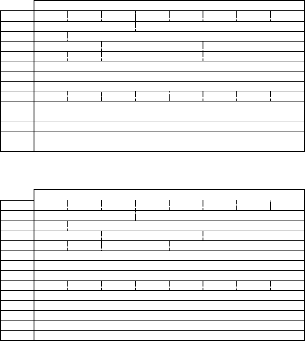
Appendix D
D-I
APPENDIX D PRODUCTS DEFAULT DATA
D.1 Product data of Applied Model Number 3 (Inquiry Data)
TABLE D-1A DR-U124X INQUIRY DATA FORMAT
Bit
Byte 76543210
0Peripheral Qualifier Peripheral device type (05h)
1RMB=1 Reserved
2 0 0 ANSI version : 2
3 0 TIOP=1 Reserved Response format : 2
4Additional length : 42 (2Ah)
5Reserved
6Reserved
7000Sync=1 0Reserve 0 0
8 ~ 15 Vendor name (8-byte ASCII code) Continue "PIONEER"
16 ~ 31 Product inquiry data (16-byte ASCII code) Continue "CD-ROM DR-124X"
32 ~ 35 Revision number (ASCII code) Ex.”0100”
36 Release Version : 20h
37 ~ 46 Revision Date(10-byte ASCII code) Continue Ex. "1995/02/08"
TABLE D-1B DR-UA124X INQUIRY DATA FORMAT
Bit
Byte 76543210
0Peripheral Qualifier Peripheral device type (05h)
1RMB=1 Reserved
2 0 0 ANSI version : 0
3 0 TIOP=1 Reserved Response format : 1
4Additional length : 42 (2Ah)
5Reserved
6Reserved
7000Sync=1 0Reserve 0 0
8 ~ 15 Vendor name (8-byte ASCII code) Continue "PIONEER"
16 ~ 31 Product inquiry data (16-byte ASCII code) Continue "CD-ROM DR-124X"
32 ~ 35 Revision number (ASCII code) Ex.”0100”
36 Release Version : 20h
37 ~ 46 Revision Date(10-byte ASCII code) Continue Ex. "1995/02/08"

CD-ROM SCSI-2 COMMAND REFERENCE MANUAL VERSION 3.1 (OB-U0077C)
D-II
TABLE D-1C DRM-624X INQUIRY DATA FORMAT
Bit
Byte 76543210
0Peripheral Qualifier Peripheral device type (05h)
1RMB=1 Reserved
2 0 0 ANSI version : 2
3 0 TIOP=1 Reserved Response format : 2
4Additional length : 42 (2Ah)
5Reserved
6Reserved
7000Sync=1 0Reserve 0 0
8 ~ 15 Vendor name (8-byte ASCII code) Continue "PIONEER"
16 ~ 31 Product inquiry data (16-byte ASCII code) Continue "CD-ROM DRM-624X"
32 ~ 35 Revision number (ASCII code) Ex.”0100”
36 Release Version : 20h
37 ~ 46 Revision Date(10-byte ASCII code) Continue Ex. "1995/02/08"

Appendix D
D-III
D.2 CD-ROM Ability Mechanical Status Page Default Data
TABLE D-2APAGE CODE 2AH : CD-ROM CAPABILITIES AND MECHANICAL STATUS PAGE DEFAULT
DATA
Bit
Byte 76543210
0Reserved Reserved Page Code (2Ah)
1Page Length (0Eh)
2Reserved
3Reserved
Reserved Multi
Session
=1
Mode 2
Form 2
=1
Mode 2
Form1
=1
Reserved Reserved XA
Commands
=0
AudioPlay
=0
4 ~ 7
32-bit field
of
Capability
Reserved ISRC
=1
UPC
=1
C2Po
supported
=0
R-W Dec.
=1
R-W
Supported
=1
CD-DA
String
=1
CD-DA
Commands
=1
bits Loading Mechanism Type
124X=001b,624X=000b
Reserved Eject
=1
Prevent
JP =1
Lock
State
Lock
=1
Reserved Sp.Mute
=1
Sp.volume
=1
8(MSB) Maximum Speed Supported (in KBps)
9DR-UA124X=706,DR-U124X/DRM-624X=777 (LSB)
10 (MSB) Number of Volume Levels Supported
11 = 256 (LSB)
12 (MSB) Buffer Size supported by Drive (in KBytes)
13 = 128 (LSB)
14 (MSB) Current Speed Selected (in KBps)
15 DR-UA124X=706,DR-U124X/DRM-624X=777 (LSB)
16 Reserved
17-20 Reserved

CD-ROM SCSI-2 COMMAND REFERENCE MANUAL VERSION 3.1 (OB-U0077C)
E-I
APPENDIX E CD-ROM COMMAND LIST (BY CODE)
TABLE E-1 CD-ROM COMMAND LIST BY CODE
Applied Model Sense Data
Code Command Name 123Contents of Information Bytes
00h TEST UNIT READY yes yes yes
01h REZERO UNIT yes yes yes
03h REQUEST SENSE yes yes yes
08h READ (6) yes yes yes Logical Block Address
0Bh SEEK (6) yes yes yes Logical Block Address
12h INQUIRY yes yes yes
15h MODE SELECT (6) 2 2 yes
16h RESERVE yes yes 5
17h RELEASE yes yes 5
1Ah MODE SENSE (6) 2 2 yes
1Bh START/STOP UNIT yes yes yes
1Ch RECEIVE DIAGNOSTIC RESULTS yes yes yes
1Dh SEND DIAGNOSTIC yes yes yes
1Eh PREVENT/ALLOW MEDIUM REMOVAL yes yes yes
25h READ CD-ROM CAPACITY yes yes yes Logical Block Address
28h READ (10) yes yes yes Logical Block Address
2Bh SEEK (10) yes yes yes Logical Block Address
2Fh VERIFY (10) yes yes -- Logical Block Address
3Bh WRITE BUFFER yes yes 5
3Ch READ BUFFER yes yes yes
40h CHANGE DEFINITION 1-- --
42h READ SUB-CHANNEL yes yes yes
43h READ TOC 4yes yes
44h READ HEADER yes yes yes Logical Block Address
45h PLAY AUDIO (10) yes yes yes Logical Block Address
47h PLAY AUDIO MSF yes yes yes Logical Block Address
48h PLAY AUDIO TRACK/INDEX yes yes yes Logical Block Address
49h PLAY TRACK RELATIVE (10) yes yes yes Logical Block Address
4Bh PAUSE/RESUME yes yes yes Logical Block Address
4Eh STOP PLAY/SCAN -- -- yes
55h MODE SELECT (10) 2 2 yes
5Ah MODE SENSE (10) 2 2 yes
A5h PLAY AUDIO (12) yes yes yes Logical Block Address
A8h READ (12) yes yes yes Logical Block Address
A9h PLAY TRACK RELATIVE (12) yes yes yes Logical Block Address
AFh VERIFY (12) yes yes -- Logical Block Address
B9h READ CD MSF -- -- 3Logical Block Address
BAh AUDIO SCAN (1) -- -- 7Logical Block Address
BBh SET CD-ROM SPEED (1) -- -- yes
BEh READ CD -- -- 3Logical Block Address
CDh AUDIO SCAN (2) yes yes 7Logical Block Address
D8h READ CD-DA -- yes 3Logical Block Address
D9h READ CD-DA MSF -- yes 3Logical Block Address
DAh SET CD-ROM SPEED (2) yes yes yes
DBh READ CD-XA -- yes yes Logical Block Address
DFh READ ALL SUBCODE -- yes 7Logical Block Address
E0h READ DRIVE STATUS yes yes yes
E3h WRITE CDP yes yes yes
E4h READ CDP yes yes yes

CD-ROM SCSI-2 Command Set
Reference Manual Version 3.1
Pioneer Electronic Corporation
4-1, Meguro 1-chome
Meguro-Ku, Tokyo 153
JAPAN
www.pioneer.co.jp
Pioneer New Media Technologies, Inc.
2265 East 220th Street
Long Beach, California 90810
UNITED STATES OF AMERICA
(310) 952-2111
www.pioneerusa.com
