Pioneer Vsx 9300Tx Users Manual ARB7313 A
VSX-9300TX 138551425VSX-9300TX OPERATING INSTRUCTIONS
VSX-9300TX to the manual 27801900-f9f6-44a9-ab57-08c36754fab8
2015-01-26
: Pioneer Pioneer-Vsx-9300Tx-Users-Manual-335123 pioneer-vsx-9300tx-users-manual-335123 pioneer pdf
Open the PDF directly: View PDF ![]() .
.
Page Count: 100
AUDIO/VIDEO MULTI-CHANNEL
RECEIVER
VSX-9300TX
Operating Instructions
Register your product at
www.pioneerelectronics.com
• Protect your new investment
The details of your purchase will be on file for reference in the event of an
insurance claim such as loss or theft.
• Improve product development
Your input helps us continue to design products that meet your needs.
• Receive a free Pioneer newsletter
Registered customers can opt in to receive a monthly newsletter.
• Receive free tips, updates and service bulletins on
your new product
VSX-9300.book 1 ページ 2004年5月21日 金曜日 午前11時28分
WARNING: Handling the cord on this product or
cords associated with accessories sold with the
product will expose you to lead, a chemical known to
the State of California and other governmental
entities to cause cancer and birth defects or other
reproductive harm.
D36-P4_En
Wash hands after handling
The exclamation point within an equilateral
triangle is intended to alert the user to the
presence of important operating and
maintenance (servicing) instructions in the
literature accompanying the appliance.
The lightning flash with arrowhead, within
an equilateral triangle, is intended to alert
the user to the presence of uninsulated
"dangerous voltage" within the product's
enclosure that may be of sufficient
magnitude to constitute a risk of electric
shock to persons.
CAUTION:
TO PREVENT THE RISK OF ELECTRIC
SHOCK, DO NOT REMOVE COVER (OR
BACK). NO USER-SERVICEABLE PARTS
INSIDE. REFER SERVICING TO QUALIFIED
SERVICE PERSONNEL.
CAUTION
RISK OF ELECTRIC SHOCK
DO NOT OPEN
D1-4-2-3_En
WARNING – TO PREVENT FIRE OR SHOCK
HAZARD, DO NOT EXPOSE THIS
APPLIANCE TO RAIN OR MOISTURE.
D1-4-2-1_En
IMPORTANT NOTICE – THE SERIAL NUMBER FOR THIS EQUIPMENT IS LOCATED IN THE REAR.
PLEASE WRITE THIS SERIAL NUMBER ON YOUR ENCLOSED WARRANTY CARD AND
KEEP IN A SECURE AREA. THIS IS FOR YOUR SECURITY. D1-4-2-6-1_En
This Class B digital apparatus complies with Canadian ICES-003.
Cet appareil numérique de la Classe B est conforme à la norme NMB-003 du Canada.
D8-10-1-3_EF
NOTE: This equipment has been tested and found to comply with the limits for a Class B digital device, pursuant to
Part 15 of the FCC Rules. These limits are designed to provide reasonable protection against harmful interference in
a residential installation. This equipment generates, uses, and can radiate radio frequency energy and, if not
installed and used in accordance with the instructions, may cause harmful interference to radio communications.
However, there is no guarantee that interference will not occur in a particular installation. If this equipment does
cause harmful interference to radio or television reception, which can be determined by turning the equipment off
and on, the user is encouraged to try to correct the interference by one or more of the following measures:
– Reorient or relocate the receiving antenna.
– Increase the separation between the equipment and receiver.
– Connect the equipment into an outlet on a circuit different from that to which the receiver is connected.
– Consult the dealer or an experienced radio/TV technician for help.
D8-10-1-2_En
Information to User
Alteration or modifications carried out without appropriate authorization may invalidate the user’s right to operate
the equipment.
D8-10-2_En
CAUTION: This product satisfies FCC regulations when shielded cables and connectors are used to connect the
unit to other equipment. To prevent electromagnetic interference with electric appliances such as radios and
televisions, use shielded cables and connectors for connections.
D8-10-3a_En
Thank you for buying this Pioneer product.
Please read through these operating
instructions so you will know how to
operate your model properly. After you have
finished reading the instructions, put them
away in a safe place for future reference.
CAUTION – TO PREVENT ELECTRIC SHOCK DO
NOT USE THIS (POLARIZED) PLUG
WITH AN EXTENSION CORD.
RECEPTACLE OR OTHER OUTLET
UNLESS THE BLADES CAN BE
FULLY INSERTED TO PREVENT
BLADE EXPOSURE.
ATTENTION –
POUR PREVENIR LES CHOCS
ELECTRIQUES, NE PAS UTILISER
CETTE FICHE POLARISEE AVEC UN
PROLONGATEUR, UNE PRISE DE
COURANT, OU UNE AUTRE SORTIE
DE COURANT, SAUF SI LES LAMES
PEUVENT ETRE INSEREES A FOND
SANS EN LAISSER AUCUNE PARTIE
A DECOUVERT.
D2-4-4-1_EF
00_Cover.fm 2 ページ 2004年5月27日 木曜日 午後9時14分
READ INSTRUCTIONS — All the safety and
operating instructions should be read before the
product is operated.
RETAIN INSTRUCTIONS — The safety and
operating instructions should be retained for
future reference.
HEED WARNINGS — All warnings on the product
and in the operating instructions should be
adhered to.
FOLLOW INSTRUCTIONS — All operating and use
instructions should be followed.
CLEANING — The product should be cleaned only
with a polishing cloth or a soft dry cloth. Never
clean with furniture wax, benzine, insecticides
or other volatile liquids since they may corrode
the cabinet.
ATTACHMENTS — Do not use attachments not
recommended by the product manufacturer as
they may cause hazards.
WATER AND MOISTURE — Do not use this
product near water — for example, near a
bathtub, wash bowl, kitchen sink, or laundry
tub; in a wet basement; or near a swimming
pool; and the like.
ACCESSORIES — Do not place this product on an
unstable cart, stand, tripod, bracket, or table.
The product may fall, causing serious injury to a
child or adult, and serious damage to the
product. Use only with a cart, stand, tripod,
bracket, or table recommended by the
manufacturer, or sold with the product. Any
mounting of the product should follow the
manufacturer’s instructions, and should use a
mounting accessory recommended by the
manufacturer.
CART — A product and cart combination should be
moved with care. Quick stops, excessive force,
and uneven surfaces may cause the product
and cart combination to overturn.
VENTILATION — Slots and openings in the cabinet
are provided for ventilation and to ensure
reliable operation of the product and to protect
it from overheating, and these openings must
not be blocked or covered. The openings should
never be blocked by placing the product on a
bed, sofa, rug, or other similar surface. This
product should not be placed in a built-in
installation such as a bookcase or rack unless
proper ventilation is provided or the
manufacturer’s instructions have been adhered
to.
POWER SOURCES — This product should be
operated only from the type of power source
indicated on the marking label. If you are not
sure of the type of power supply to your home,
consult your product dealer or local power
company.
LOCATION – The appliance should be installed in a
stable location.
NONUSE PERIODS – The power cord of the
appliance should be unplugged from the outlet
when left un-used for a long period of time.
GROUNDING OR POLARIZATION
• If this product is equipped with a polarized
alternating current line plug (a plug having one
blade wider than the other), it will fit into the
outlet only one way. This is a safety feature. If
you are unable to insert the plug fully into the
outlet, try reversing the plug. If the plug should
still fail to fit, contact your electrician to replace
your obsolete outlet. Do not defeat the safety
purpose of the polarized plug.
• If this product is equipped with a three-wire
grounding type plug, a plug having a third
(grounding) pin, it will only fit into a grounding
type power outlet. This is a safety feature. If you
are unable to insert the plug into the outlet,
contact your electrician to replace your obsolete
outlet. Do not defeat the safety purpose of the
grounding type plug.
POWER-CORD PROTECTION — Power-supply
cords should be routed so that they are not likely
to be walked on or pinched by items placed
upon or against them, paying particular
attention to cords at plugs, convenience
receptacles, and the point where they exit from
the product.
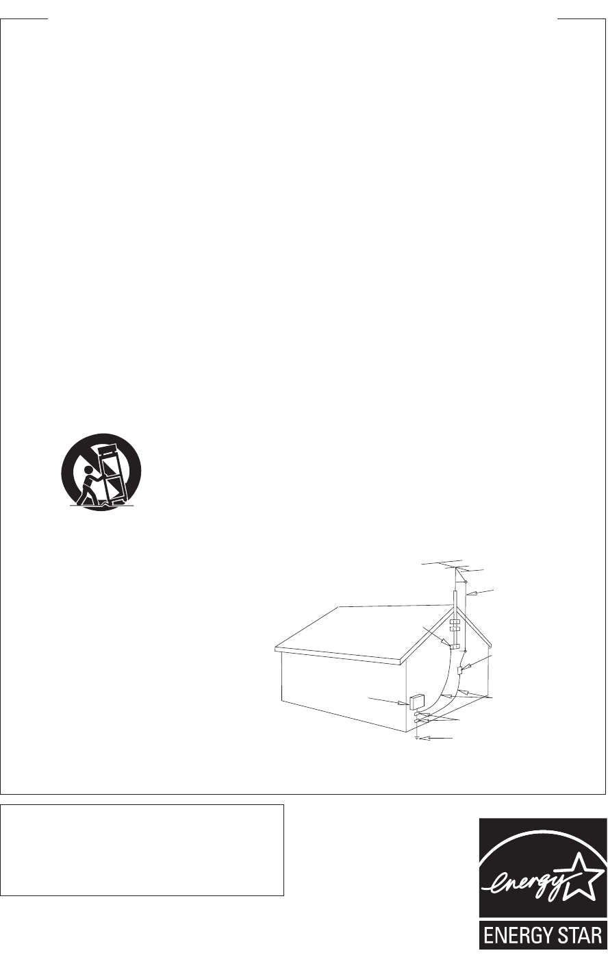
OUTDOOR ANTENNA GROUNDING — If an
outside antenna or cable system is connected to
the product, be sure the antenna or cable
system is grounded so as to provide some
protection against voltage surges and built-up
static charges. Article 810 of the National
Electrical Code, ANSI/NFPA 70, provides
information with regard to proper grounding of
the mast and supporting structure, grounding of
the lead-in wire to an antenna discharge unit,
size of grounding conductors, location of
antenna-discharge unit, connection to
grounding electrodes, and requirements for the
grounding electrode. See Figure A.
LIGHTNING — For added protection for this
product during a lightning storm, or when it is
left unattended and unused for long periods of
time, unplug it from the wall outlet and
disconnect the antenna or cable system. This
will prevent damage to the product due to
lightning and power-line surges.
POWER LINES — An outside antenna system
should not be located in the vicinity of overhead
power lines or other electric light or power
circuits, or where it can fall into such power
lines or circuits. When installing an outside
antenna system, extreme care should be taken
to keep from touching such power lines or
circuits as contact with them might be fatal.
OVERLOADING — Do not overload wall outlets,
extension cords, or integral convenience
receptacles as this can result in a risk of fire or
electric shock.
OBJECT AND LIQUID ENTRY — Never push
objects of any kind into this product through
openings as they may touch dangerous voltage
points or short-out parts that could result in a
fire or electric shock. Never spill liquid of any
kind on the product.
SERVICING — Do not attempt to service this
product yourself as opening or removing covers
may expose you to dangerous voltage or other
hazards. Refer all servicing to qualified service
personnel.
DAMAGE REQUIRING SERVICE — Unplug this
product from the wall outlet and refer servicing
to qualified service personnel under the
following conditions:
• When the power-supply cord or plug is
damaged.
• If liquid has been spilled, or objects have fallen
into the product.
• If the product has been exposed to rain or water.
• If the product does not operate normally by
following the operating instructions. Adjust only
those controls that are covered by the operating
instructions as an improper adjustment of other
controls may result in damage and will often
require extensive work by a qualified technician
to restore the product to its normal operation.
• If the product has been dropped or damaged in
any way.
• When the product exhibits a distinct change in
performance — this indicates a need for service.
REPLACEMENT PARTS — When replacement parts
are required, be sure the service technician has
used replacement parts specified by the
manufacturer or have the same characteristics
as the original part. Unauthorized substitutions
may result in fire, electric shock, or other
hazards.
SAFETY CHECK — Upon completion of any service
or repairs to this product, ask the service
technician to perform safety checks to
determine that the product is in proper
operating condition.
WALL OR CEILING MOUNTING — The product
should not be mounted to a wall or ceiling.
HEAT — The product should be situated away from
heat sources such as radiators, heat registers,
stoves, or other products (including amplifiers)
that produce heat.
GROUND
CLAMP
ELECTRIC
SERVICE
EQUIPMENT
ANTENNA
LEAD IN
WIRE
ANTENNA
DISCHARGE UNIT
(NEC SECTION 810-20)
GROUNDING CONDUCTORS
(NEC SECTION 810-21)
GROUND CLAMPS
POWER SERVICE GROUNDING
ELECTRODE SYSTEM
(NEC ART 250, PART H)
NEC — NATIONAL ELECTRICAL CODE
Fig. A
IMPORTANT SAFETY INSTRUCTIONS
D1-4-2-2_En
This product is for general household purposes. Any
failure due to use for other than household purposes
(such as long-term use for business purposes in a
restaurant or use in a car or ship) and which
requires repair will be charged for even during the
warranty period. K041_En
For U.S. and Australia Model
C67-7-3_En
VSX-9300.book 3 ページ 2004年5月21日 金曜日 午前11時28分

4
En
Contents
01 Before you start
Features
. . . . . . . . . . . . . . . . . . . . . . . . . . . . . . . . . . . 6
Checking the supplied accessories
. . . . . . . . . . . . . . 6
Ventilation
. . . . . . . . . . . . . . . . . . . . . . . . . . . . . . . . . 7
Installing the receiver
. . . . . . . . . . . . . . . . . . . . . . . . . 7
Opening the front panel
. . . . . . . . . . . . . . . . . . . . . . . 7
Using the remote control
. . . . . . . . . . . . . . . . . . . . . . 7
Loading the batteries
. . . . . . . . . . . . . . . . . . . . . . . . 7
Operating range of the remote control
. . . . . . . . . . . 8
02 5 minute guide
Introduction to home theater
. . . . . . . . . . . . . . . . . . . 9
Setting up for Surround Sound
. . . . . . . . . . . . . . . . . . 9
Automatically setting up for surround sound
. . . . . . 12
Other problems when using the Auto Surround
Setup
. . . . . . . . . . . . . . . . . . . . . . . . . . . . . . . . . . . 14
Checking the settings on your DVD (or other)
player
. . . . . . . . . . . . . . . . . . . . . . . . . . . . . . . . . . . . 14
Playing a source
. . . . . . . . . . . . . . . . . . . . . . . . . . . . 14
03 Connecting your equipment
Rear panel
. . . . . . . . . . . . . . . . . . . . . . . . . . . . . . . . 15
About the video converter
. . . . . . . . . . . . . . . . . . . . . 16
About cable types
. . . . . . . . . . . . . . . . . . . . . . . . . . . 17
Analog audio cables
. . . . . . . . . . . . . . . . . . . . . . . . 17
Digital audio cables
. . . . . . . . . . . . . . . . . . . . . . . . 17
Video cables
. . . . . . . . . . . . . . . . . . . . . . . . . . . . . . 17
When making cable connections
. . . . . . . . . . . . . . 17
Connecting your TV
. . . . . . . . . . . . . . . . . . . . . . . . . 18
Connecting a DVD player
. . . . . . . . . . . . . . . . . . . . . 19
Connecting the multichannel analog outputs
. . . . 20
Connecting a satellite/cable receiver or other
set-top box
. . . . . . . . . . . . . . . . . . . . . . . . . . . . . . . . 21
Connecting a VCR or DVD recorder
. . . . . . . . . . . . . 22
Connecting other video sources
. . . . . . . . . . . . . . . . 23
Using the component video jacks
. . . . . . . . . . . . . . . 24
Connecting digital audio sources
. . . . . . . . . . . . . . . 25
Connecting analog audio sources
. . . . . . . . . . . . . . 26
Connecting a component to the front panel inputs
. . 27
Installing your speaker system
. . . . . . . . . . . . . . . . . 28
Connecting the speakers
. . . . . . . . . . . . . . . . . . . . 29
Placing the speakers
. . . . . . . . . . . . . . . . . . . . . . . 29
Connecting antennas
. . . . . . . . . . . . . . . . . . . . . . . . 30
AM loop antenna
. . . . . . . . . . . . . . . . . . . . . . . . . . 30
FM wire antenna
. . . . . . . . . . . . . . . . . . . . . . . . . . 30
Connecting external antennas
. . . . . . . . . . . . . . . . 30
Plugging in the receiver
. . . . . . . . . . . . . . . . . . . . . . 31
About the AC outlet
. . . . . . . . . . . . . . . . . . . . . . . . 31
04 Controls and displays
Front panel
. . . . . . . . . . . . . . . . . . . . . . . . . . . . . . . . 32
Display
. . . . . . . . . . . . . . . . . . . . . . . . . . . . . . . . . . . 34
Remote control
. . . . . . . . . . . . . . . . . . . . . . . . . . . . . 35
05 Listening to your system
Auto playback
. . . . . . . . . . . . . . . . . . . . . . . . . . . . . . 37
Listening in surround sound
. . . . . . . . . . . . . . . . . . . 37
The MOVIE listening modes
. . . . . . . . . . . . . . . . . . 38
The MUSIC listening modes
. . . . . . . . . . . . . . . . . . 39
Dolby Pro Logic IIx Music settings
. . . . . . . . . . . . . 39
Adjusting the advanced effect level
. . . . . . . . . . . . 40
Listening in stereo
. . . . . . . . . . . . . . . . . . . . . . . . . . 40
Listening with headphones
. . . . . . . . . . . . . . . . . . . . 40
Using the multichannel analog inputs
. . . . . . . . . . . 41
Listening with Acoustic Calibration EQ
. . . . . . . . . . . 41
Selecting the input signal type
. . . . . . . . . . . . . . . . . 42
Using the surround back channel . . . . . . . . . . . . . . 43
Listening with virtual surround back speakers . . . . . 44
Using the audio scaler for Hi-bit and Hi-sampling . . 44
Using Midnight and Loudness listening . . . . . . . . . . 45
Using the tone control . . . . . . . . . . . . . . . . . . . . . . . 45
Switching the tone control on or off . . . . . . . . . . . . 45
Adjusting the bass and treble . . . . . . . . . . . . . . . . 45
Reducing noise during playback. . . . . . . . . . . . . . . . 46
Listening to dual mono soundtracks. . . . . . . . . . . . . 46
06 Using the tuner
Finding a station. . . . . . . . . . . . . . . . . . . . . . . . . . . . 47
Tuning directly to a station . . . . . . . . . . . . . . . . . . . . 47
MPX mode . . . . . . . . . . . . . . . . . . . . . . . . . . . . . . . 48
Memorizing station presets . . . . . . . . . . . . . . . . . . . 48
Listening to memorized station presets . . . . . . . . . 49
Naming station presets . . . . . . . . . . . . . . . . . . . . . 49
07 The Surround Setup menu
Making receiver settings from the Surround
Setup menu . . . . . . . . . . . . . . . . . . . . . . . . . . . . . . . 50
Surround back speaker setting. . . . . . . . . . . . . . . . . 51
Normal surround setting . . . . . . . . . . . . . . . . . . . . . 51
Speaker Setting . . . . . . . . . . . . . . . . . . . . . . . . . . . 51
Channel Level. . . . . . . . . . . . . . . . . . . . . . . . . . . . . 52
Speaker Distance. . . . . . . . . . . . . . . . . . . . . . . . . . 53
VSX-9300.book 4 ページ 2004年5月21日 金曜日 午前11時28分

5
En
08 Controlling other equipment
Using the remote control with other components
. . 54
Recalling preset codes
. . . . . . . . . . . . . . . . . . . . . . 54
Programming signals from other remote controls
. . 55
Controls for TVs
. . . . . . . . . . . . . . . . . . . . . . . . . . . . 56
Controls for other components
. . . . . . . . . . . . . . . . 57
Direct function
. . . . . . . . . . . . . . . . . . . . . . . . . . . . . 59
Multi Operation and System Off
. . . . . . . . . . . . . . . . 59
Programming a multi-operation or a shutdown
sequence
. . . . . . . . . . . . . . . . . . . . . . . . . . . . . . . . 59
Using multi operations
. . . . . . . . . . . . . . . . . . . . . 60
Using System off
. . . . . . . . . . . . . . . . . . . . . . . . . . 61
Switching components on and off using the
12 volt trigger
. . . . . . . . . . . . . . . . . . . . . . . . . . . . . . 61
Operating other Pioneer components with this
unit’s sensor
. . . . . . . . . . . . . . . . . . . . . . . . . . . . . . 61
09 Using other functions
Making an audio or a video recording
. . . . . . . . . . . 62
Adjusting the delay of a soundtrack
. . . . . . . . . . . . . 62
Watching video and audio sources independently
. . 63
Dimming the display
. . . . . . . . . . . . . . . . . . . . . . . . 63
Switching the speaker impedance
. . . . . . . . . . . . . . 64
Advanced remote control features
. . . . . . . . . . . . . . 64
Editing remote control display names
. . . . . . . . . . 64
Adjusting the remote control backlight
. . . . . . . . . 65
Clearing remote control settings
. . . . . . . . . . . . . . 65
Resetting the system
. . . . . . . . . . . . . . . . . . . . . . . . 66
10 Other connections
Second Zone speaker B setup
. . . . . . . . . . . . . . . . . 67
Switching the speaker system
. . . . . . . . . . . . . . . . 67
Bi-amping your front speakers
. . . . . . . . . . . . . . . . . 68
Bi-wiring your speakers
. . . . . . . . . . . . . . . . . . . . . . 68
Multi-room listening
. . . . . . . . . . . . . . . . . . . . . . . . 69
Making multi-room connections
. . . . . . . . . . . . . . 69
Using the multi-room controls
. . . . . . . . . . . . . . . . 70
Connecting an IR receiver
. . . . . . . . . . . . . . . . . . . . 71
Connecting additional amplifiers
. . . . . . . . . . . . . . . 71
Using the USB interface
. . . . . . . . . . . . . . . . . . . . . 72
Connecting a PC for Advanced MCACC output
. . . . 73
Advanced MCACC output using your PC
. . . . . . . . 73
11 Advanced setup
The System Setup menu
. . . . . . . . . . . . . . . . . . . . . 74
THX CINEMA Setup
. . . . . . . . . . . . . . . . . . . . . . . . 75
The Input Assign menu
. . . . . . . . . . . . . . . . . . . . . 75
Function Rename
. . . . . . . . . . . . . . . . . . . . . . . . . 76
PHONO/LINE Setup
. . . . . . . . . . . . . . . . . . . . . . . 78
Multi-Room and IR receiver setup
. . . . . . . . . . . . . 78
12 Volt Trigger
. . . . . . . . . . . . . . . . . . . . . . . . . . . . 79
The Expert setup menu
. . . . . . . . . . . . . . . . . . . . . . 79
Crossover Network
. . . . . . . . . . . . . . . . . . . . . . . . 80
Fine Channel Level
. . . . . . . . . . . . . . . . . . . . . . . . 81
Fine Channel Delay
. . . . . . . . . . . . . . . . . . . . . . . . 81
Acoustic Calibration EQ
. . . . . . . . . . . . . . . . . . . . 82
Professional Acoustic Calibration
. . . . . . . . . . . . . 84
Using Professional Acoustic Calibration
. . . . . . . . 85
Bass Peak Level
. . . . . . . . . . . . . . . . . . . . . . . . . . 87
Dynamic Range Control
. . . . . . . . . . . . . . . . . . . . 88
12 Additional information
Troubleshooting
. . . . . . . . . . . . . . . . . . . . . . . . . . . . 89
Power
. . . . . . . . . . . . . . . . . . . . . . . . . . . . . . . . . . 89
No sound
. . . . . . . . . . . . . . . . . . . . . . . . . . . . . . . 90
Other audio problems
. . . . . . . . . . . . . . . . . . . . . . 91
Video
. . . . . . . . . . . . . . . . . . . . . . . . . . . . . . . . . . . 92
Settings. . . . . . . . . . . . . . . . . . . . . . . . . . . . . . . . . 93
Display . . . . . . . . . . . . . . . . . . . . . . . . . . . . . . . . . 93
Remote control . . . . . . . . . . . . . . . . . . . . . . . . . . . 94
USB interface . . . . . . . . . . . . . . . . . . . . . . . . . . . . 94
Surround sound formats . . . . . . . . . . . . . . . . . . . . . 96
Dolby. . . . . . . . . . . . . . . . . . . . . . . . . . . . . . . . . . . 96
DTS . . . . . . . . . . . . . . . . . . . . . . . . . . . . . . . . . . . . 96
About THX® . . . . . . . . . . . . . . . . . . . . . . . . . . . . . . 97
Preset code brands . . . . . . . . . . . . . . . . . . . . . . . . . 98
Specifications . . . . . . . . . . . . . . . . . . . . . . . . . . . . . 99
Maintenance of external surfaces . . . . . . . . . . . . . . 99
VSX-9300.book 5 ページ 2004年5月21日 金曜日 午前11時28分
Before you start
01
6
En
Chapter 1
Before you start
Features
• Easy setup using Advanced Multichannel
Acoustic Calibration (MCACC)
Setting up for home theater sound is as easy as
connecting your speakers, a DVD player or other source,
and your TV. The Auto Surround Setup provides a quick
but accurate surround sound setup, while for complete
surround sound control you still have access to the full
range of surround sound settings.
In addition, the Professional Acoustic Calibration setup
measures the reverb characteristics of your listening
area, allowing you to customize your system calibration
with the help of a graphical output that can be displayed
on-screen, or using a computer.
•Dolby Digital and DTS decoding, including Dolby
Digital EX, DTS 96/24 and DTS-ES
Dolby Digital and DTS decoding brings theater sound
right into your home with up to six channels of surround
sound, including a special LFE (Low Frequency Effects)
channel for deep, realistic sound effects.
The built-in Dolby Pro Logic IIx and DTS Neo:6 decoders
not only provide full surround sound decoding for Dolby
Surround sources, but will also generate convincing
surround sound for any stereo source.
Also, with the addition of a surround back speaker, you
can take advantage of the built-in Dolby Digital EX and
DTS-ES decoders for six-channel surround sound.
• Seamless video conversion
With the Pioneer video converter, you can use a wide
range of cables interchangeably, giving you more
flexibility when making video connections.
• USB digital interface
It is possible to listen to audio sources from your
computer by connecting to the USB interface on the rear
of this receiver.
• Fine-tuned to world-class standards
With the cooperation of the world-class studio engineers
at AIR Studios, this receiver amplifier has been
designated AIR Studios Monitor.
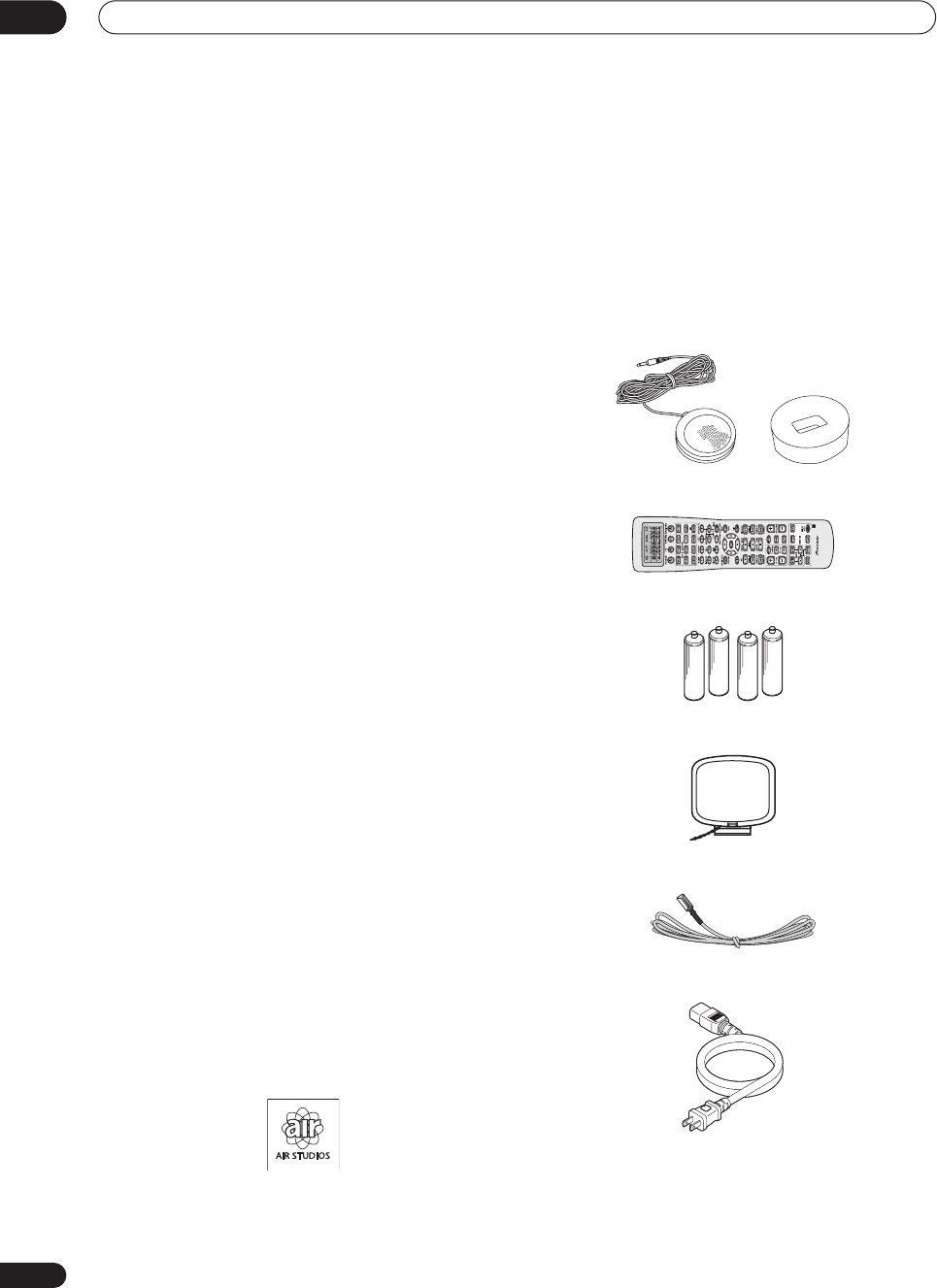
Checking the supplied accessories
Please check that you've received the following supplied
accessories:
• Setup microphone and stand
• Remote control unit
• Alkaline batteries (AA IEC LR6) x 4
• AM loop antenna
• FM wire antenna
• Power cord
• Warranty card
• These operating instructions
VSX-9300.book 6 ページ 2004年5月21日 金曜日 午前11時28分
Before you start 01
7
En
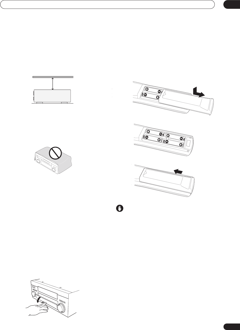
Ventilation
When installing this unit, make sure to leave space
around the unit for ventilation to improve heat dispersal
(at least 8 in. (20 cm) at the top). If not enough space is
provided between the unit and walls or other equipment,
heat will build up inside, interfering with performance
and/or causing malfunctions.
Slot and openings in the cabinet are provided for
ventilation and to protect the equipment from
overheating. To prevent fire hazard, do not place anything
on top of the unit, make sure the openings are never
blocked or covered with items (such as newspapers,
table-cloths and curtains), and do not operate the
equipment on thick carpet or a bed.
Installing the
receiver
• When installing this unit, make sure to put it on a
level and stable surface.
Don’t install it on the following places:
– on a color TV (the screen may distort)
– near a cassette deck (or close to a device that gives off
a magnetic field). This may interfere with the sound.
– in direct sunlight
– in damp or wet areas
– in extremely hot or cold areas
– in places where there is vibration or other movement
– in places that are very dusty
– in places that have hot fumes or oils (such as a kitchen)
Opening the front panel
To open the front panel, push gently on the lower third of
the panel with your finger.
Using the remote control
Loading the batteries
Load the batteries into the remote control as shown
below using alkaline batteries (AA IEC LR6) batteries.
When you notice a decrease in the operating range,
replace all batteries with new ones.
Caution
Incorrect use of batteries can result in hazards such as
leakage and bursting. Please observe the following:
• Don’t mix new and old batteries together.
• Don’t use different kinds of batteries together—
although they may look similar, different batteries
may have different voltages.
• Make sure that the plus and minus ends of each
battery match the indications in the battery compart-
ment.
•Remove batteries from equipment that isn’t going to
be used for a month or more.
• When disposing of used batteries, please comply
with governmental regulations or environmental
public instruction’s rules that apply in your country or
area.
H048 En
8 inches
(20 cm)
Receiver
VSX-9300.book 7 ページ 2004年5月21日 金曜日 午前11時28分
Before you start
01
8
En
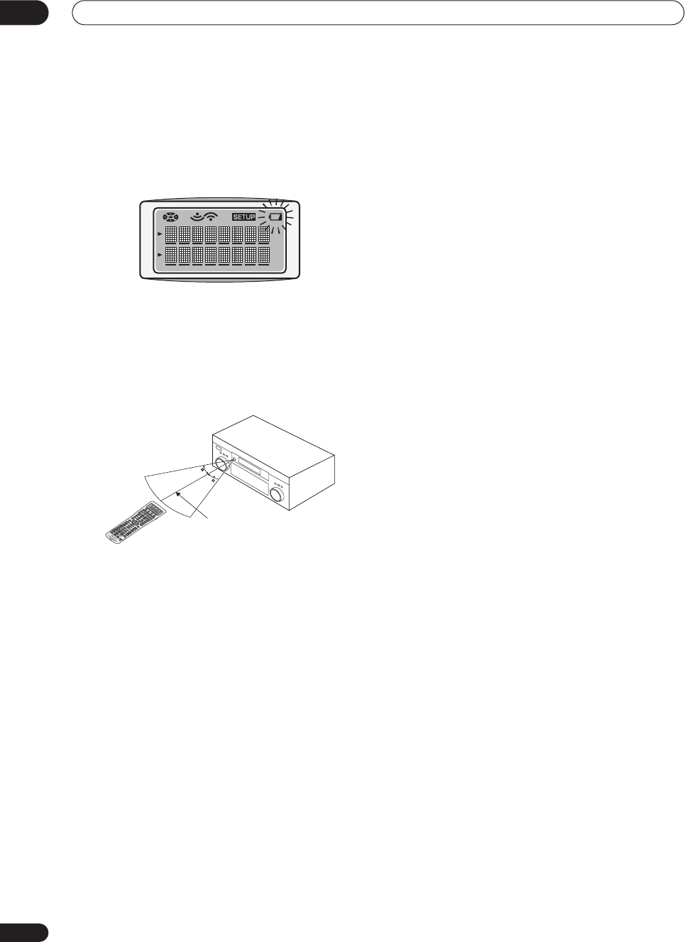
Remote control battery indicator
When the batteries get too weak to operate the remote
control properly an indicator warning screen will appear
on the remote. Change the batteries as shown above.
This must be done within five minutes or all your remote
control settings will be cleared.
Operating range of the remote control
The operating range is quite large, but please keep in
mind the following when using the remote control:
• Make sure that there are no obstacles between the
remote and the remote sensor on the unit.
•The remote has a range of about 23 feet (7 meters).
• Remote operation may become unreliable if strong
sunlight or fluorescent light is shining on the unit’s
remote sensor.
•Remote controllers for different devices can interfere
with each other. Avoid using remotes for other
equipment located close to this unit.
30
23 feet (7m)
30
VSX-9300.book 8 ページ 2004年5月21日 金曜日 午前11時28分
5 minute guide 02
9
En
Chapter 2:
5 minute guide
Introduction to home theater
You are probably used to using stereo equipment to listen to music, but may not be used to home theater systems that
give you many more options (such as surround sound) when listening to soundtracks.
Home theater refers to the use of multiple audio tracks to create a surround sound effect, making you feel like you're
in the middle of the action or concert. The surround sound you get from a home theater system depends not only on
the speakers you have set up in your room, but also on the source and the sound settings of the receiver.
DVD-Video has become the basic source material for home theater due to its size, quality, and ease of use. Depending
on the DVD, you can have up to seven different audio tracks coming from one disc, all of them being sent to different
speakers in your system. This is what creates a surround sound effect and gives you the feeling of ‘being there’.
This receiver will automatically decode Dolby Digital, DTS, or Dolby Surround DVD-Video discs, according to your
speaker setup. In most cases, you won’t have to make changes for realistic surround sound, but other possibilities (like
listening to a CD with multichannel surround sound) are explained in
Listening to your system
on page 37.
Setting up for Surround Sound
This receiver was designed with the easiest possible setup in mind, so with the following quick setup guide, you should
have your system hooked up for surround sound in no time at all. In most cases, you can simply leave the receiver in
the default settings.
Be sure to complete all connections before connecting this unit to the AC power source.
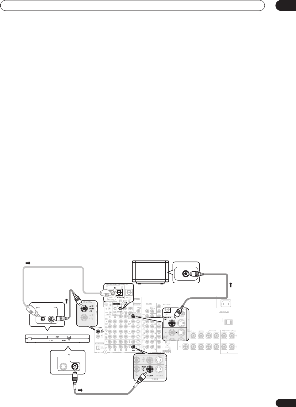
1 Hook up your DVD player.
For surround sound, you’ll want to hook up using a digital connection from the DVD player to the receiver. You can do
this with either a coaxial, or an optical connection (you don’t need to connect both). If you hook up using an optical
cable, you should refer to
The Input Assign menu
on page 75 to assign the optical input to
DVD/LD
.
Use a standard RCA video cable to connect your DVD player video output to the receiver using the jacks shown below.
2 Hook up your TV.
Use a standard RCA video cable to connect your receiver to the TV using the jacks as shown below.
AC IN
SWITCHED 100W(0.8A)MAX
SELECTABLE
CENTER
S
CE
Optical cable
DVD player
TV
DIGITAL OUT
VIDEO OUT
VIDEO IN
Coaxial digital
audio cable
Standard RCA
video cable
Standard RCA
video cable
VSX-9300.book 9 ページ 2004年5月21日 金曜日 午前11時28分
5 minute guide
02
10
En
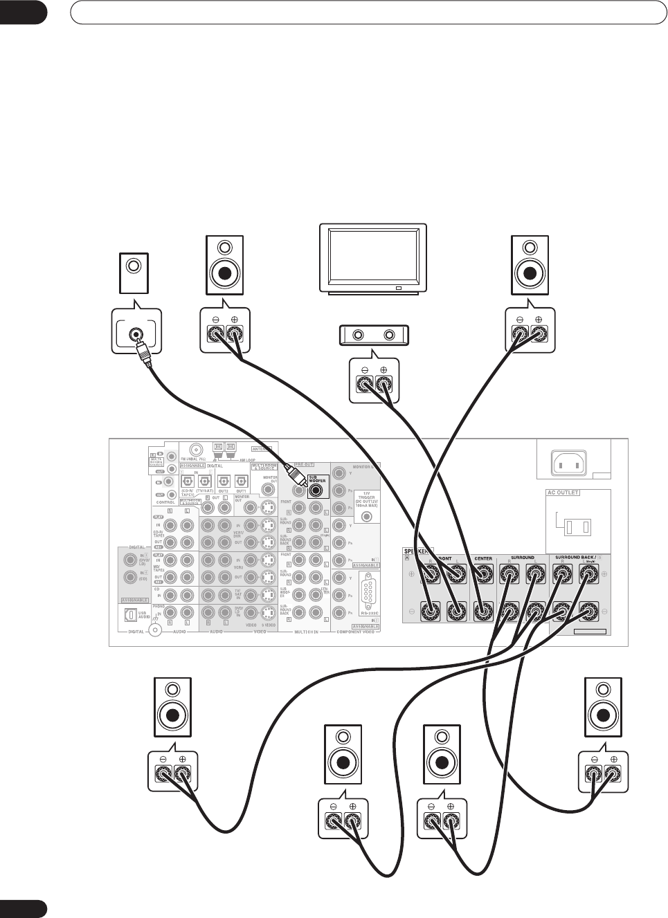
3 Connect your speakers.
To take full advantage of the receiver’s surround sound capabilities connect front, center, surround and surround back
speakers, as well as a subwoofer. Although this is ideal, other configurations with fewer speakers—no subwoofer or
no center speaker, or even no surround speakers—will work. At the very least, front left and right speakers only are
necessary. Note that your main surround speakers should always be connected as a pair, but you can connect just
one surround back speaker if you like (it must be connected to the left surround back terminal).
You can use speakers with a nominal impedance between 6–16
Ω
(please see
Switching the speaker impedance
on
page 64 if you plan to use speakers with an impedance of less than 8
Ω
).
AC IN
SWITCHED 100W(0.8A)MAX
SELECTABLE
CENTER
VSX-9300TX
Front
left
Front
right
Center
Surround
left
Surround
right
Surround
back right
Surround
back left
LINE LEVEL
INPUT
Subwoofer
TV
VSX-9300.book 10 ページ 2004年5月21日 金曜日 午前11時28分
5 minute guide 02
11
En
Each speaker connection on the receiver comprises a
positive (+) red, and negative (–) black terminal. For
proper sound you should take care to match these up
with the terminals on the speakers themselves.
• If you only have one surround back speaker, hook it
up to the surround back left (
Single
) terminal.
• If you’re not using a subwoofer, change the front
speaker setting (see
Speaker Setting
on page 51) to
LARGE
.
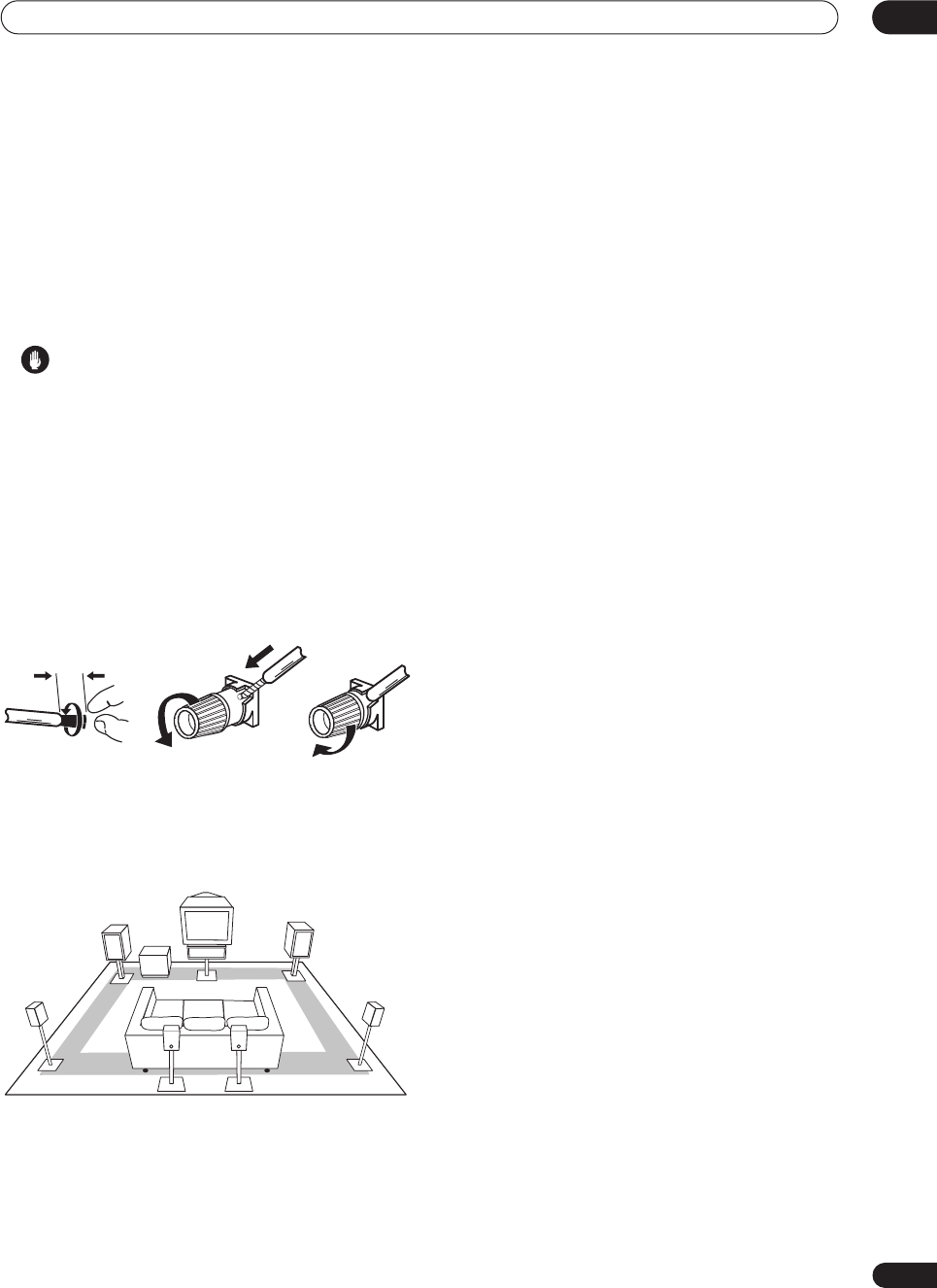
Caution
• Make sure that all the bare speaker wire is twisted
together and inserted fully into the speaker terminal.
If any of the bare speaker wire touches the back panel
it may cause the power to cut off as a safety measure.
Make sure that the speaker cable you’re going to use is
properly prepared with about
3
/
8
in. (10 mm) of insulator
stripped from each wire, and the exposed wire strands
twisted together (
fig. A
).
To connect a terminal, unscrew the terminal a few turns
until there is enough space to insert the exposed wire
(
fig. B
). Once the wire is in position, tighten the terminal
until the wire is firmly clamped (
fig. C
).
Where you place the speakers will have a big effect on the
sound. Place your speakers as shown below for the best
surround sound effect. For more tips on speaker
placement, see
Placing the speakers
on page 29.
4Plug in the receiver and switch it on, followed by
your DVD player, your subwoofer and the TV.
Make sure you’ve set the video input on your TV to this
receiver. Check the manual that came with the TV if you
don’t know how to do this.
Also make sure that
DVD/LD
is showing in the receiver’s
display, indicating that the DVD input is selected. If it
isn’t, press
DVD/LD
on the remote control to set the
receiver to the DVD input.
5Use the on-screen Auto Surround setup to set up
your system.
See
Automatically setting up for surround sound
on the
next page for more on this.
6Play a DVD, and adjust the volume to your liking.
In addition to the basic playback explained in
Playing a
source
on page 14, there are several other sound options
you can select. See
Listening to your system
on page 37
for more on this. See also
Making receiver settings from
the Surround Setup menu
on page 50 for more setup
options.
• If you’re not familiar with the proper DVD settings,
refer to
Checking the settings on your DVD (or other)
player
on page 14.
3/8 inch (10mm)
fig. A fig. B fig. C
Front R
Front L
Surround
L
Surround
back R
Surround
R
Sub-
woofer
Center
Surround
back L
VSX-9300.book 11 ページ 2004年5月21日 金曜日 午前11時28分
5 minute guide
02
12
En
Automatically setting up for
surround sound
The Auto Surround Setup measures the acoustic
characteristics of your listening area, taking into account
ambient noise, speaker size and distance, and tests for
both channel delay and channel level. After you have set
up the microphone provided with your system, the
receiver uses the information from a series of test tones
to optimize the speaker settings and equalization for your
particular room.
Make sure you do this before moving on to
Playing a
source
on page 14.
Important
• Make sure the microphone and speakers are not
moved during the Auto Surround Setup.
• Using the Auto Surround Setup will overwrite any
existing speaker settings in the receiver.
• The receiver will automatically exit the on-screen
menu after three minutes of inactivity.
Caution
• The test tones used in the Auto Surround Setup are
output at high volume.
1 Switch on the receiver and your TV.
Use the
RECEIVER
button to switch on.
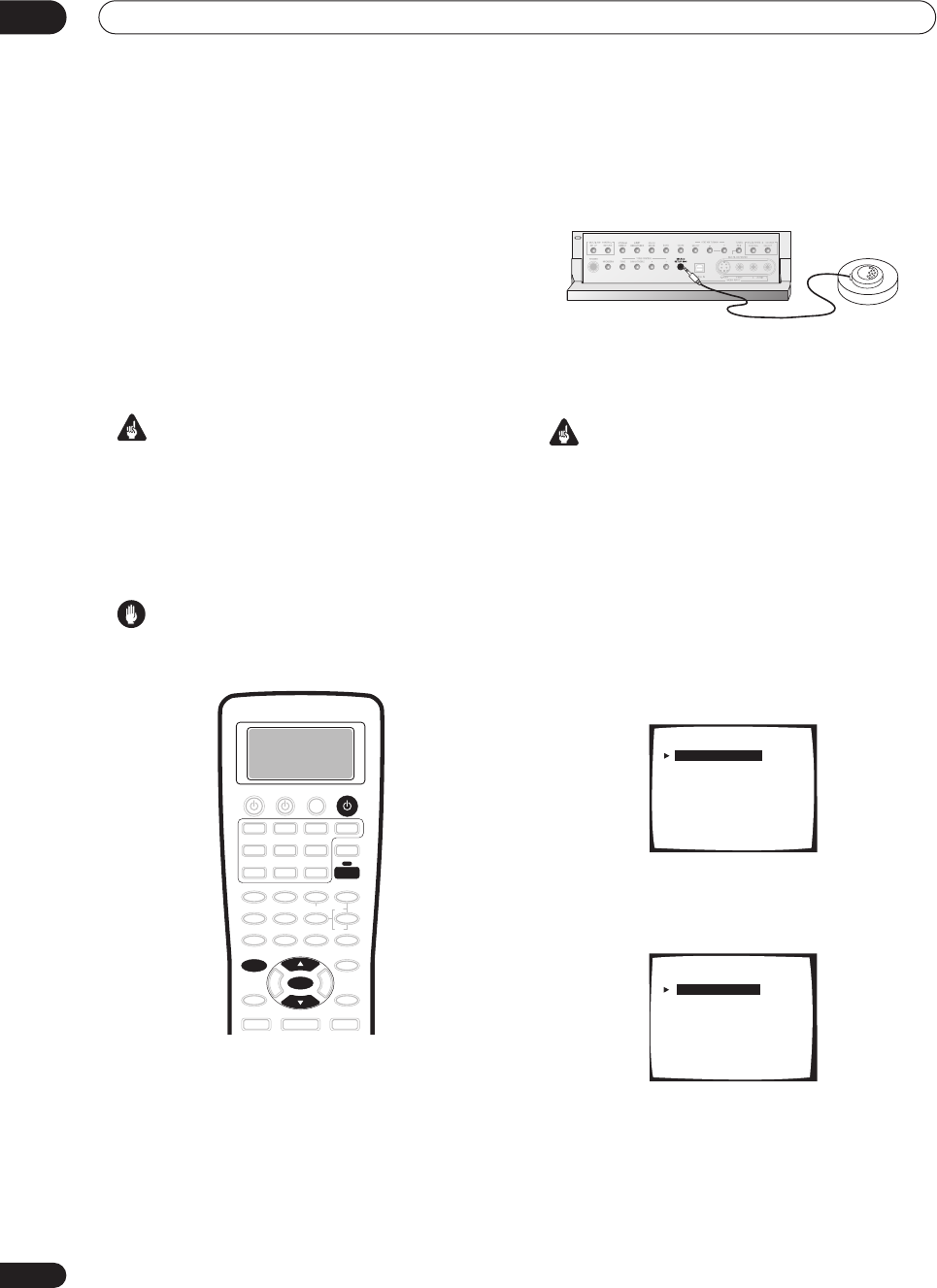
2 Connect the microphone to the MCACC SETUP
MIC jack on the front panel.
Make sure there are no obstacles between the speakers
and the microphone.
• Place the microphone on the supplied microphone
stand (shown above) for the best results with the
Auto Surround Setup.
Important
•If you have a tripod, use it to
place the microphone so
that it’s about ear level
at your normal listening
position. Otherwise, place the microphone at ear
level using a table or a chair.
3Press RECEIVER on the remote control, then press
the SYSTEM SETUP button.
An on-screen display (OSD) appears on your TV. Use the
/
(cursor up/down) buttons and
ENTER
on the remote
control to navigate through the screens and select menu
items.
4 ‘Surround Setup’ should be highlighted. Press
ENTER.
5 ‘SurrBack System’ should be highlighted. Press
ENTER.
SYSTEM SETUP
ENTER
RECEIVER
RECEIVER
System Setup
[ 1. Surround Setup ]
[ 2. THX CINEMA Setup ]
[ 3. Input Assign ]
[ 4. Function Rename ]
[ 5. PHONO/LINE Setup ]
[ 6. Multi Room ]
[ 7. 12V Trigger ]
[ Exit ]
1.Surround Setup
[ SurrBack System ]
[ Auto Setting ]
[ Normal ]
[ Expert ]
[ Exit ]
VSX-9300.book 12 ページ 2004年5月21日 金曜日 午前11時28分
5 minute guide 02
13
En
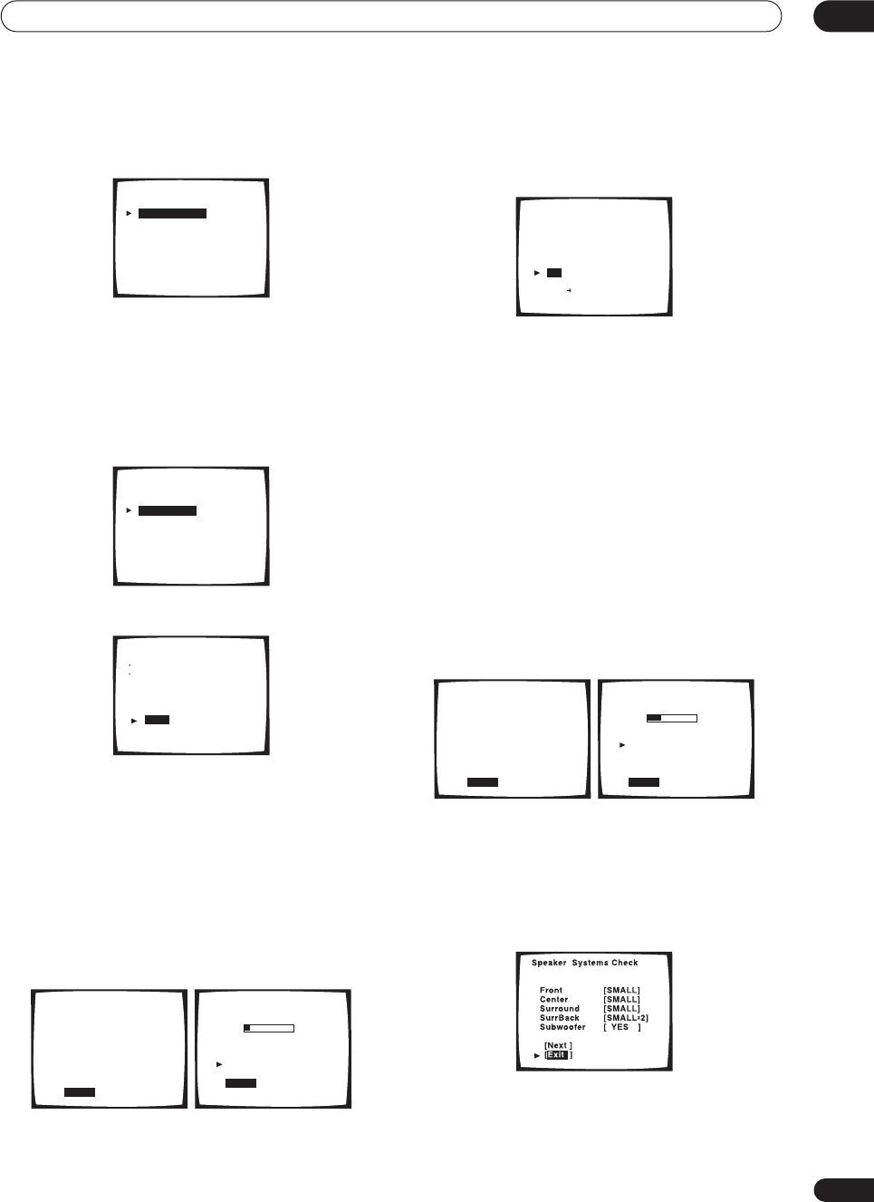
6 Make sure ‘Normal System’ is selected, then
select ‘Exit’.
•If you are planning on bi-amping your front speakers,
or setting up a separate speaker system in another
room, read through
Surround back speaker setting
on
page 51 and make sure to connect your speakers as
necessary before continuing to step 7.
7 ‘Auto Setting’ should be highlighted. Press
ENTER.
8 Follow the instructions on-screen.
• Make sure the microphone is connected.
•If you’re using a subwoofer, switch it on and turn up
the volume.
• See below for notes regarding high background
noise levels and other possible interference.
9 Make sure ‘Start’ is selected, then press ENTER.
A progress report is displayed on-screen while the
receiver outputs test tones to determine the speakers
present in your setup. Try to be as quiet as possible while
it’s doing this.
• Do not turn down the volume during the test tones.
This may result in incorrect speaker settings.
10 Confirm the speaker configuration in the OSD.
The configuration shown on-screen should reflect the
actual speakers you have.
If the speaker configuration displayed isn’t correct, use
the
/
(cursor up/down) buttons to select
Retry
. Follow
the instructions from step 8.
If the configuration is incorrect and you want to input the
settings manually, select
ERR
Fix SP
. Use
/
(cursor
up/down) to select the speaker and to specify the size
(and number for surround back). When you’re finished,
go to the next step.
If you see an
ERR
message in the right side column, there
may be a problem with the speaker connection. If
selecting
Retry
(above) doesn’t fix the problem, turn off
the power and check the speaker connections.
11 Make sure ‘OK’ is selected, then press ENTER.
A progress report is displayed on-screen while the
receiver outputs more test tones to determine the
optimum receiver settings for channel level, speaker
distance, and acoustic calibration EQ.
Again, try to be as quiet as possible while this is
happening.
12 The Auto Surround Setup has finished! Select
‘Exit’ to go back to the Surround Setup menu.
The MCACC indicator continues to light to show the
surround settings are complete.
The settings made in the Auto Surround Setup should
give you excellent surround sound from your system, but
it is also possible to adjust these settings manually using
the Surround Setup menu (starting on page 50).
SurrBack System
[ Normal System
[ Second Zone
[ Front Bi-Amp
[ MR&S
[ Exit
]
]
]
]
]
1.Surround Setup
[ SurrBack System ]
[ Auto Setting ]
[ Normal ]
[ Expert ]
[ Exit ]
Auto Surround Setup
Set microphone
Turn on subwoofer
[ Start ]
[ Cancel ]
Auto Surround Setup
Please Wait
Caution!!
Test tone is
output loudly.
[ Cancel ]
Auto Surround Setup
Now Analyzing•••
Environment Check
Ambient Noise [OK]
Microphone [OK]
Speaker YES/NO [OK]
[Cancel]
Check!!
Front [ YES ]
Center [ YES ]
Surround [ YES ]
SurrBack [ YESX2 ]
Subwoofer
[ YES ]
[OK]
[Retry]
[ERR Fix SP.]
[Return to Menu]
Auto Surround Setup
Please Wait
Caution!!
Test tone is
output loudly.
[ Cancel ]
Auto Surround Setup
Now Analyzing•••
Surround Analysis
Speaker Systems [OK]
Speaker Distance [OK]
Channel Level [OK]
Acoustic Cal EQ [OK]
[Cancel]
VSX-9300.book 13 ページ 2004年5月21日 金曜日 午前11時28分

5 minute guide
02
14
En
You can also choose to view all the settings by selecting
Next
. Press
ENTER
after you have finished checking
each screen. When you’re finished, select
Exit
to go back
to the Surround Setup menu.
Note
•If you leave a check screen for over three minutes, or
if you select
Cancel
at any time during the Auto
Surround Setup, the receiver automatically exits and
no settings will be made.
• Remember to disconnect the microphone after
you’ve finished the Auto Surround Setup.
Other problems when using the Auto
Surround Setup
If the room environment is not optimal for the Auto
Surround Setup (too much background noise, echo off
the walls, obstacles blocking the speakers from the
microphone) the final settings may be incorrect. Check
for household appliances (air conditioner, fridge, fan,
etc.), that may be affecting the environment and switch
them off if necessary.
Some older TVs may interfere with the operation of the
microphone. If this seems to be happening, switch off the
TV when doing the Auto Surround Setup.
Checking the settings on your DVD
(or other) player
Before continuing, you may want to check the digital
audio output settings on your DVD player and digital
satellite receiver.
• Check that your DVD player/satellite receiver is
set to output Dolby Digital, DTS and 88.2/96kHz PCM
(2 channel) audio.
If there is an option for MPEG audio, set this to convert
the MPEG audio to PCM.
If you connected the multichannel analog outputs of the
player to this receiver, make sure that the player is set to
output multichannel analog audio.
Note
• Depending on your DVD player or source discs, you
may only get digital 2 channel stereo and analog
sound. In this case, select one of the surround
listening modes (see
Listening in surround sound
on
page 37 if you need to do this) if you want
multichannel surround sound.
Playing a source
Here are the basic instructions for playing a source (such
as a DVD disc) with your home theater system.
1 Turn on the power of the playback component
(for example a DVD player), your TV and subwoofer
(if you have one).
•If your source is the TV’s built-in tuner, then switch to
the channel you want to watch, otherwise make sure
that the TV’s video input is set to this receiver. (For
example, if you connected this receiver to the
VIDEO
1
jacks on your TV, make sure that
VIDEO 1
input is
now selected.)
2If the receiver isn’t already on, press
RECEIVER
to switch it on.
3 Change the receiver input to the source you
want to play.
You can use the front panel
MULTI JOG
dial or the
dedicated
MULTI CONTROL
buttons on the remote
control.
4Start playback of the DVD (or other component).
If you’re playing a Dolby Digital or DTS surround sound
DVD disc, you should hear surround sound. If you are
playing a stereo source, you will only hear sound from the
front left/right speakers in the default listening mode.
• See also
Listening to your system
on page 37 for
more information on different ways of listening to
sources.
5Use the MASTER VOLUME control (front panel or
remote) to adjust the volume level.
•Turn down the volume of your TV so that all the sound
is coming from the speakers connected to this
receiver.
Note
• For more detailed surround sound setup, see
The
Surround Setup menu
on page 50.
VSX-9300.book 14 ページ 2004年5月21日 金曜日 午前11時28分
Connecting your equipment 03
15
En
Chapter 3
Connecting your equipment
This receiver provides you with almost limitless possibilities for connecting your audio/video system, but it doesn’t
have to be difficult. Depending on your needs, you could be up and running in no time after a few simple connections.
This section has been designed so that you can read through this short introduction, then jump to the specific
connections that you need to make. For a basic home theater setup, you may only need to look through the TV, DVD
and speaker connections.
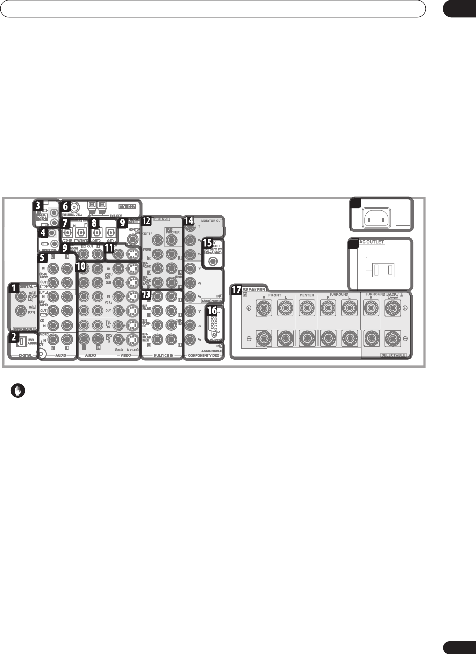
Rear panel
Caution
• Before making or changing the connections, switch
off the power and disconnect the power cord from the
power outlet. Plugging in components should be the
last connection you make with your system.
1 Digital audio coaxial inputs
Two coaxial digital audio inputs for connecting digital
audio sources to this receiver. All the inputs are freely
assignable to input functions for maximum flexibility.
• If a connected component does not correspond to
the input function (
DVD/LD
, etc.), see
Assigning the
digital inputs
on page 75 to assign it properly.
2 USB audio input
The USB audio input allows you to use your PC as a
playback source for audio. See
Using the USB interface
on page 72 for connection details.
3 IR input/output
An IR connection allows you to connect an external
remote control sensor, when your component system is
in a closed cabinet or shelving unit, for example. See
Connecting an IR receiver
on page 71 for connection
details.
4 Control input/output
Mini-plug terminals for connection to other Pioneer
components to enable you to control all your equipment
from a single remote sensor. See
Operating other Pioneer
components with this unit’s sensor
on page 61 for
connection details.
5 Stereo analog audio source inputs/outputs
Four sets of analog audio jacks for connection to audio
sources such as CD players, tape decks and turntables.
The
CD-R/TAPE1
and
MD/TAPE2
functions also feature
outputs for recording. See
Connecting analog audio
sources
on page 26 for connection details.
•The grounding (
) terminal is for use with turntables
that require it. See
Connecting analog audio sources
on page 26 for connection details.
6 Antenna terminals
Connections for AM and FM radio antennas. See
Connecting antennas
on page 30 for connection details.
7 Digital audio optical inputs
Two optical digital audio inputs for connecting digital
audio sources to this receiver. All the inputs are freely
assignable to input functions for maximum flexibility.
AC IN
SWITCHED 100W
(
0.8A
)
MAX
AC IN
4
1
18
1
1
19
1
VSX-9300.book 15 ページ 2004年5月21日 金曜日 午前11時28分
Connecting your equipment
03
16
En
• If a connected component does not correspond to
the input function (
DVD/LD
, etc.), see
Assigning the
digital inputs
on page 75 to assign it properly.
8 Digital audio outputs
Two optical digital audio outputs for connecting to a CD-
R, MD or other digital recorder. See
Connecting digital
audio sources
on page 25 for connection details.
9 Multi-room and source outputs
The analog audio outputs are for connection to a second
amplifier in a separate room. The
MULTI-ROOM &
SOURCE
composite video output is for connection to a
second monitor or TV in a separate room. See
Multi-room
listening
on page 69.
10 Audio/video source inputs
Each of the six source input functions has stereo analog
audio jacks, a composite video jack and an S-video jack
for basic connections. On top of these, you can assign
digital audio and component video jacks to input
functions as necessary. As well as audio/video inputs,
the two input functions
VCR 1/DVR
and
VCR 2
also have
audio/video outputs for recording. See
Connecting a VCR
or DVD recorder
on page 22 for connection details.
11 Monitor video outputs
Two video outputs consisting of a standard composite
video output and an S-video output, for connection to
monitors and TVs. See
Connecting your TV
on page 18 for
connection details.
12 Multichannel pre-amplifier outputs
Multichannel pre-amp outputs that you can use to
connect separate amplifiers for center, surround,
surround back and subwoofer channels. See
Cnnecting
additional amplifiers
on page 71 for connection details.
13 Multichannel analog audio inputs
7.1 channel analog inputs for connection to a component
with multichannel analog outputs. See
Connecting the
multichannel analog outputs
on page 20 for connection
details.
14 Component video inputs/output
The two component video inputs are freely assignable to
any of the audio/video input functions. The component
video output is for connection to a monitor or TV. See
Using the component video jacks
on page 24 for
connection details.
15 12V trigger jack
This terminal outputs DC 12V according to the input
functions (100 mA max.). See
Switching components on
and off using the 12 volt trigger
on page 61 for connection
details.
16 RS-232C connector
This port is provided for connecting a personal computer
for graphical output when using Advanced MCACC.
17 Speaker terminals
These are the main speaker terminals for front, center,
surround and surround back speakers. See
Installing
your speaker system
on page 28 for connection details.
18 AC power inlet
Connect the supplied power cord here.
19 AC power outlet
(Switched 100W max.)
This 120V AC power outlet can be used to power another
component in your setup (up to 100 W). Power to this
outlet is switched off when the receiver is in standby.
About the video converter
The video converter allows you to connect various video
sources using composite, S-video or component video
connections and the signal will be output through all of
the
MONITOR VIDEO OUT
jacks. The only exception is
component video input, which is only output from the
component video output. Therefore, if you want to
connect any source using component video, you must
also connect your TV using component video. If several
video components are connected to the same input
function, the converter gives priority to component, S-
video, then composite (in that order).
The following chart shows when the video signal will be
converted fro
m the vari
ous video inputs (left column) for
output to the
MONITOR VIDEO OUT
jacks (top row):
• The
mark above indicates that the component
video input must be assigned before it will be output
(see
Assigning the component video inputs
on
page 76 for more on this).
•When recording video sources however, you won’t be
able to record sources connected to the component
video inputs. With composite and S-video sources,
they must be connected using the same type of video
cable as you used to connect the recorder to the
receiver.
• Also note that this feature is available with NTSC
signals only. For a PAL signal, make sure you’ve used
the same type of cable for your video component and
monitor connections.
Video
terminal
MONITOR OUT
VIDEO
(Composite) S-VIDEO COMPONENT
VIDEO
VIDEO IN
(Composite)
S-VIDEO IN
COMPONENT
VIDEO IN
VSX-9300.book 16 ページ 2004年5月21日 金曜日 午前11時28分
Connecting your equipment 03
17
En
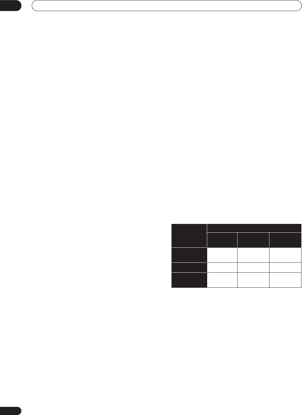
About cable types
Analog audio cables
Use stereo RCA phono cables to connect analog audio
components. These cables are typically red and white,
and you should connect the red plugs to R (right)
terminals and white plugs to L (left) terminals.
Digital audio cables
Commercially available coaxial digital audio cables or
optical cables should be used to connect digital
components to this receiver.
• When connecting optical cables, be careful when
inserting the plug not to damage the shutter
protecting the optical socket.
• When storing optical cable, coil loosely. The cable
may be damaged if bent around sharp corners.
• You can also use a standard RCA video cable for
coaxial digital connections.
Video cables
Standard RCA video cables
These cables are the most common type of video
connection and should be used to connect to the
composite video terminals. They have yellow plugs to
distinguish them from cables for audio.
S-video cables
S-video cables give you clearer picture reproduction than
regular video cables by sending separate signals for the
luminance and color.
Component video cables
Use component video cables to get the best possible
color reproduction of your video source. The color signal
of the TV is divided into the luminance (
Y
) signal and the
color (
P
B
and
P
R
) signals and then output. In this way,
interference between the signals is avoided.
When making cable connections
Be careful not to arrange cables in a manner that bends
the cables over the top or around this unit. If the cables
are laid on top of the unit, the magnetic field produced by
the transformers in this unit may cause a humming noise
to come from the speakers.
L
R
Coaxial digital audio cable Optical cable
VIDEO
S Video
Y
P
B
P
R
Green
Blue Red
VSX-9300.book 17 ページ 2004年5月21日 金曜日 午前11時28分
Connecting your equipment
03
18
En
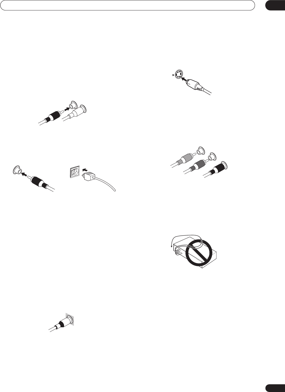
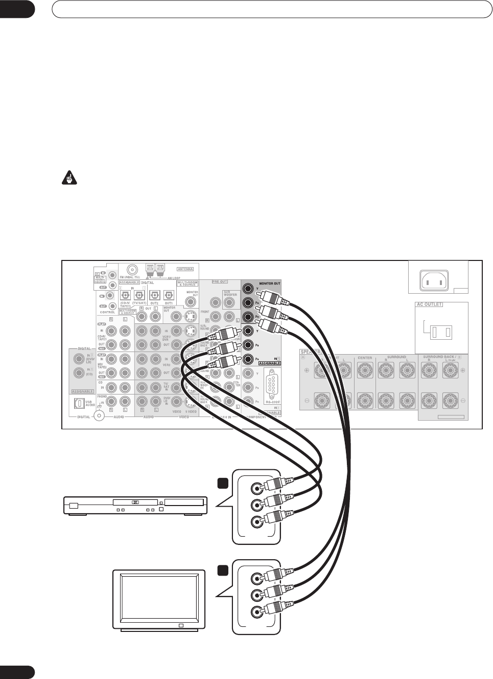
Connecting your TV
This page shows you how to connect your TV to the
receiver. To be able to play the sound from the TV’s built-
in tuner, connect the analog audio outputs from your TV
to this receiver.
If your TV has a built-in digital decoder, you can connect
the digital audio output to this receiver to enjoy Dolby
Digital and DTS sound from digital TV broadcasts.
1 Connect the MONITOR OUT video jack on this
receiver to a video input on your TV.
Make sure you don’t connect to the
MONITOR OUT
connection for
MULTI ROOM & SOURCE
.
• You can use a standard RCA video cable to connect
to the composite video jack, or for higher quality
video, you can use an S-video cable to connect to the
S-video jack (
S-VIDEO
).
• See
Using the component video jacks
on page 24 if
you want to use the component video outputs to
connect this receiver to your TV.
• See
About the video converter
on page 16 if you plan
on connecting your other video components using
different types of video cables than for your TV.
2Connect the analog audio outputs from your TV
to the TV/SAT inputs on this receiver.
• Use a stereo RCA phono cable for the connection.
3 Connect an optical digital audio output from
your TV to the DIGITAL 1 (TV/SAT) input on this
receiver.
• Use an optical cable for the connection.
• If your TV only has a coaxial digital output, you can
connect it to one of the coaxial inputs on this receiver
using a coaxial digital audio cable. When you set up
the receiver you’ll need to tell the receiver which
input you connected the TV to (see
Assigning the
digital inputs
on page 75).
Note
• If your TV doesn’t have a digital audio output, omit
step
3
above.
AC IN
SWITCHED 100W(0.8A)MAX
SELECTABLE
CENTER
TV
VIDEO
IN S-VIDEO
IN
ANALOG AUDIO OUT
LR
VSX-9300TX
DIGITAL AUDIO OUT
OPTICAL COAXIAL
1
3
2
VSX-9300.book 18 ページ 2004年5月21日 金曜日 午前11時28分
Connecting your equipment 03
19
En
Connecting a DVD player
Different DVD players offer a different selection of
connections, but all should give you at least a digital
audio output, stereo analog audio outputs and a video
output. Additionally, you may have a player with
multichannel analog audio outputs and different kinds of
video outputs to choose from.
1 Connect a coaxial digital audio output on your
DVD player to the DIGITAL 3 (DVD/LD) input on this
receiver.
• Use a coaxial digital audio cable for the connection.
• If your DVD player only has an optical digital output,
you can connect it to one of the optical inputs on this
receiver using an optical cable. When you set up the
receiver you’ll need to tell the receiver which input
you connected the player to (see
Assigning the digital
inputs
on page 75).
2If your DVD player only has stereo analog audio
outputs, connect these to the DVD/LD AUDIO inputs
on this receiver.
• Use a stereo RCA phono cable for the connection.
•If your DVD player has multichannel analog outputs,
see
Connecting the multichannel analog outputs
below for how to connect it.
3 Connect a composite or S-video output on your
DVD player to the DVD/LD VIDEO or DVD/LD S-
VIDEO input on this receiver.
• Use a standard RCA video cable or an S-video cable
for the connection.
• See
About the video converter
on page 16 if you plan
to use a different type of video cable than you used to
connect your TV.
•If your player also has a component video output, you
can connect this too. See
Using the component video
jacks
on page 24 for more on this.
AC IN
SWITCHED 100W(0.8A)MAX
SELECTABLE
CENTER
AUDIORL S-VIDEOOPTICAL
DIGITAL OUT ANALOG OUT VIDEO OUT
COAXIAL
DVD player
VSX-9300TX
1 2 3
VSX-9300.book 19 ページ 2004年5月21日 金曜日 午前11時28分
Connecting your equipment
03
20
En
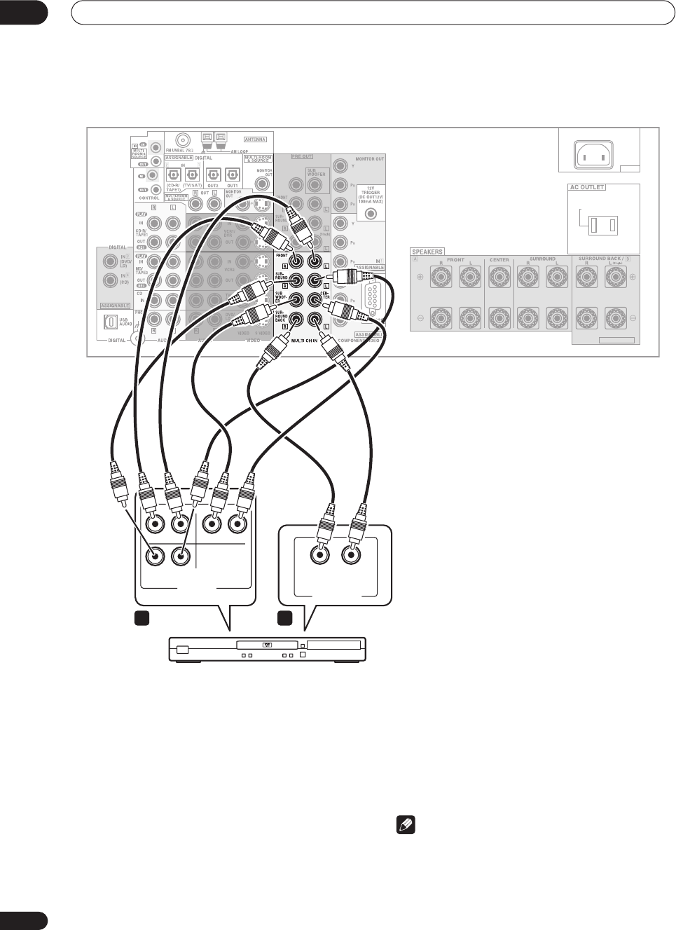
Connecting the multichannel analog outputs
For DVD Audio and SACD playback, your DVD player may
have 5.1, 6.1 or 7.1 channel analog outputs (depending
on whether your player supports surround back
channels).
1 Connect the front, surround, center and
subwoofer outputs on your DVD player to the
corresponding MULTI CH IN jack on this receiver.
•Use standard RCA phono cables for the connections.
• Take care to connect each output to its
corresponding input on the receiver.
2If your DVD player also has outputs for surround
back channels, connect these to the corresponding
MULTI CH IN jacks on this receiver.
•Use standard RCA phono cables for the connections.
•If there is only a single surround back output, be sure
to connect it to the
SURROUND BACK L
jack on this
receiver.
Note
•To listen to multichannel analog audio you’ll need to
press
MULTI CH INPUT
on the remote (see
Using the
multichannel analog inputs
on page 41 for more on
this).
AC IN
SWITCHED 100W(0.8A)MAX
SELECTABLE
CENTER
RL
RL
RL
MULTI CH. OUT
SURR.
BACK
FRONT SUB W. CENTER
SURR.
DVD player
MULTI CH
OUTPUT
VSX-9300TX
1 2
VSX-9300.book 20 ページ 2004年5月21日 金曜日 午前11時28分
Connecting your equipment 03
21
En
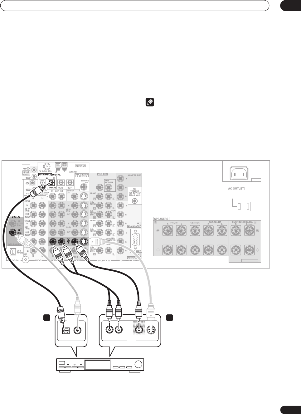
Connecting a satellite/cable
receiver
or other set-top box
Satellite and cable receivers, and terrestrial digital TV
tuners are all examples of so-called ‘set-top boxes’.
1Connect a set of audio/video outputs on the set-
top box component to the TV/SAT AUDIO and VIDEO
inputs on this receiver.
• Use a stereo RCA phono cable for the audio
connection and a standard RCA video or S-video
cable for the video connection.
• See
About the video converter
on page 16 if you plan
to use a different type of video cable than you used to
connect your TV.
2 Connect an optical digital audio output from
your set-top box component to the DIGITAL 1 (TV/
SAT) input on this receiver.
• Use an optical cable for the connection.
• If your set-top box only has a coaxial digital output,
you can connect it to one of the coaxial inputs on this
receiver using a coaxial digital audio cable. When
you set up the receiver you’ll need to tell the receiver
which input you connected the set-top box to (see
Assigning the digital inputs
on page 75).
Note
•If your satellite/cable receiver doesn’t have a digital
audio output, omit step
2
above.
• If you’ve already connected your TV to the
TV/SAT
inputs above, simply choose another input. However,
you’ll need to tell the receiver which input you
connected the set-top box to (see
Assigning the
digital inputs
on page 75).
AC IN
SWITCHED 100W(0.8A)MAX
SELECTABLE
CENTER
DIGITAL OUT
AV OUT
VIDEO S-VIDEOAUDIORL
2 1
OPTICAL COAXIAL
VSX-9300TX
STB
VSX-9300.book 21 ページ 2004年5月21日 金曜日 午前11時28分
Connecting your equipment
03
22
En
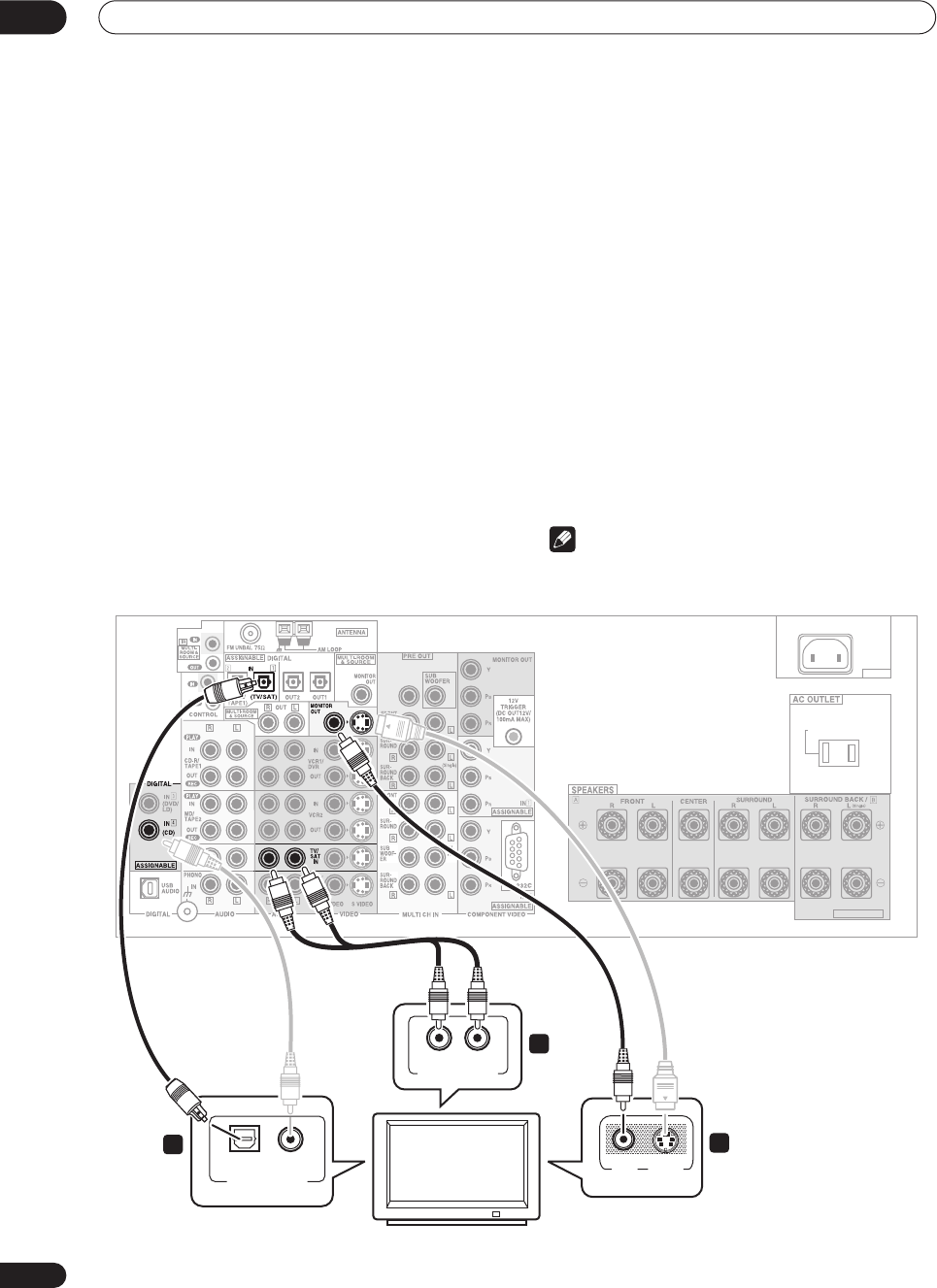
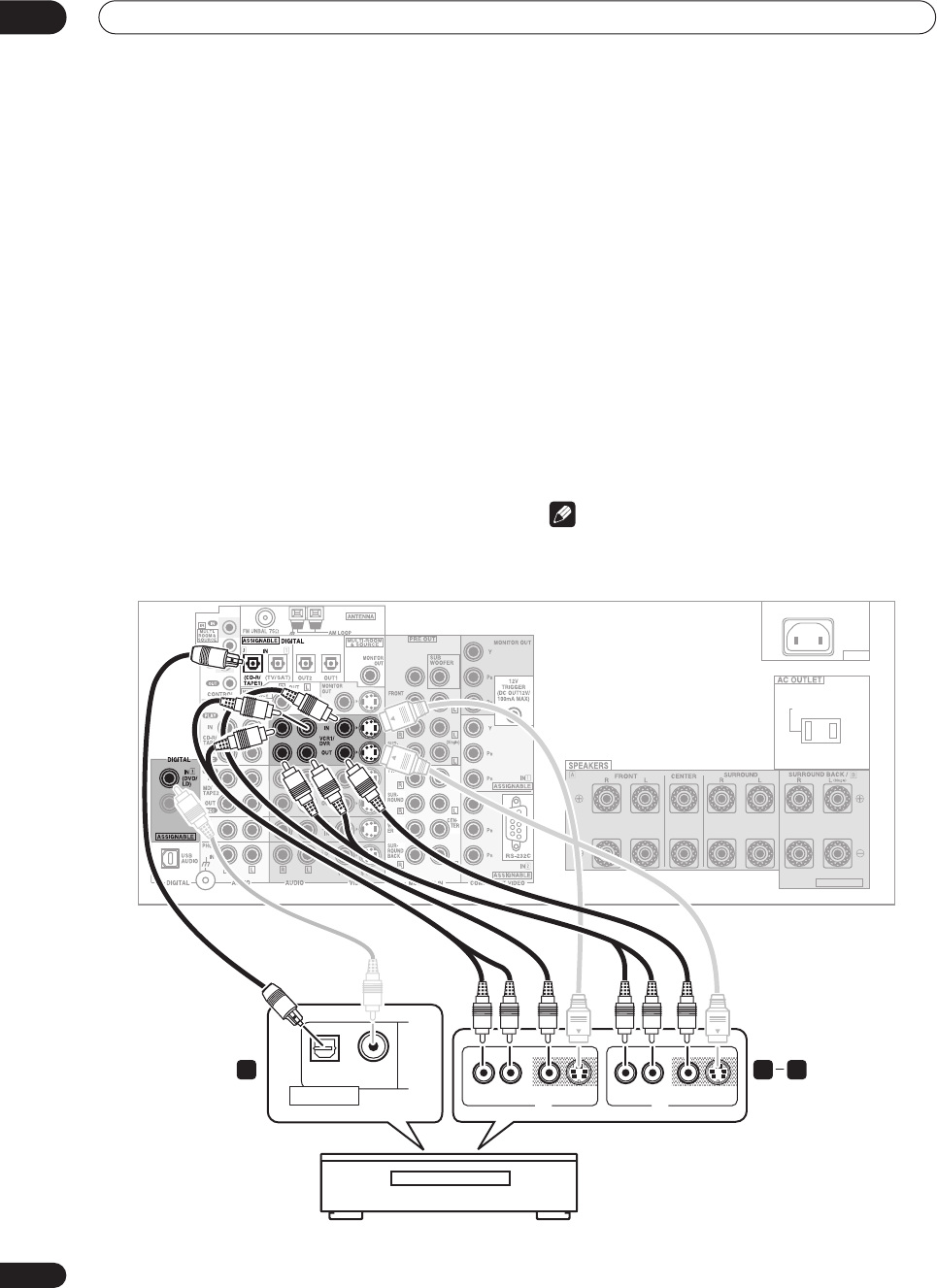
Connecting a VCR or DVD recorder
This receiver has two sets of audio/video inputs and
outputs suitable for connecting analog or digital video
recorders, including VCRs, DVD-recorders and HDD
recorders.
• See
About the video converter
on page 16 if you plan
to use a different type of video cable than you used to
connect your TV.
1 Connect a set of audio/video outputs on the
recorder to the VCR1/DVR AUDIO and VIDEO inputs
on this receiver.
• Use a stereo RCA phono cable for the audio
connection and a standard RCA video or S-video
cable for the video connection.
• For a second recorder, use the
VCR2
inputs.
2 Connect a set of audio/video inputs on the
recorder to the VCR1/DVR AUDIO and VIDEO outputs
on this receiver.
• Use a stereo RCA phono cable for the audio
connection and a standard RCA video or S-video
cable for the video connection.
• For a second recorder, use the
VCR2
outputs.
3Connect an optical digital audio output from the
recorder to a digital input on this receiver.
The example illustration below shows a recorder
connected to the optical
DIGITAL 2 (CD-R/TAPE1)
input.
When you set up the receiver you’ll need to tell the
receiver which input you connected the recorder to (see
Assigning the digital inputs
on page 75).
• Use a coaxial digital audio cable or an optical cable
for the connection depending on the type of input you
used.
• The digital outputs from another recorder can be
connected to any spare digital audio input on this
receiver. You can assign it when setting up the
receiver (see
Assigning the digital inputs
on page 75).
Note
•If your video component doesn’t have a digital audio
output, omit step
3
above.
AC IN
SWITCHED 100W(0.8A)MAX
SELECTABLE
CENTER
AV OUT
VIDEOAUDIORL
AV IN
S-VIDEO AUDIORL VIDEO S-VIDEO
OPTICAL COAXIAL
DIGITAL OUT
1 23
VSX-9300TX
DVR, VCR, etc.
VSX-9300.book 22 ページ 2004年5月21日 金曜日 午前11時28分
Connecting your equipment 03
23
En
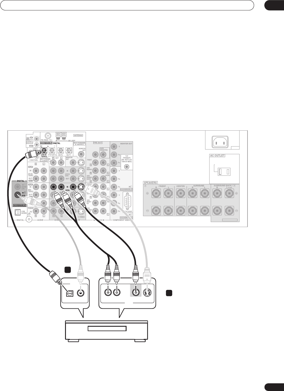
Connecting other video sources
You can basically use any of the audio/video inputs on
this receiver for any kind of video source. The example
illustration below shows a component connected to the
VCR2
inputs.
1 Connect the analog audio outputs and a video
output of the source component to a set of spare
audio/video inputs on this receiver.
• Use a stereo RCA phono cable for the audio
connection and a standard RCA video or S-video
cable for the video connection.
• See
About the video converter
on page 16 if you plan
to use a different type of video cable than you used to
connect your TV.
2 If the source component has a digital audio
output, connect it to a spare digital audio input on
this receiver.
• Use a coaxial digital audio cable or an optical cable
for the connection depending on the type of input you
used.
• You may need to assign the digital input you used
when setting up the receiver (see
Assigning the
digital inputs
on page 75).
AC IN
SWITCHED 100W(0.8A)MAX
SELECTABLE
CENTER
DIGITAL OUT
AV OUT
VIDEO S-VIDEOAUDIO
OPTICAL COAXIAL RL
VSX-9300TX
LD player, video player, TV game, etc.
1
2
VSX-9300.book 23 ページ 2004年5月21日 金曜日 午前11時28分
Connecting your equipment
03
24
En
Using the component video jacks
Component video should deliver superior picture quality
when compared to composite or S-video. A further
advantage (if your source and TV are both compatible) is
progressive-scan video, which delivers a very stable,
flicker-free picture. See the manuals that came with your
TV and source component to check whether they are
compatible with progressive-scan video.
Important
•If you connect any source component to the receiver
using a component video input, you should also have
your TV connected to this receiver's component video
MONITOR
output.
1 Connect the component video outputs of your
source to a set of component video inputs on this
receiver.
Use a three-way component video cable for the
connection.
2Assign the component video inputs to the input
source you’ve connected.
This must be done so that they can be used in
conjunction with the audio/video input(s) to which you
have connected the component above (see
Assigning the
component video inputs
on page 78
for more on this).
3Connect the COMPONENT VIDEO MONITOR OUT
jacks on this receiver to the component video inputs
on your TV or monitor.
• Use a three-way component video cable.
AC IN
SWITCHED 100W(0.8A)MAX
SELECTABLE
CENTER
Y
P
B
P
R
COMPONENT
VIDEO OUT
Y
P
B
P
R
COMPONENT
VIDEO IN
1
2
TV
VSX-9300TX
DVD player
VSX-9300.book 24 ページ 2004年5月21日 金曜日 午前11時28分
Connecting your equipment 03
25
En
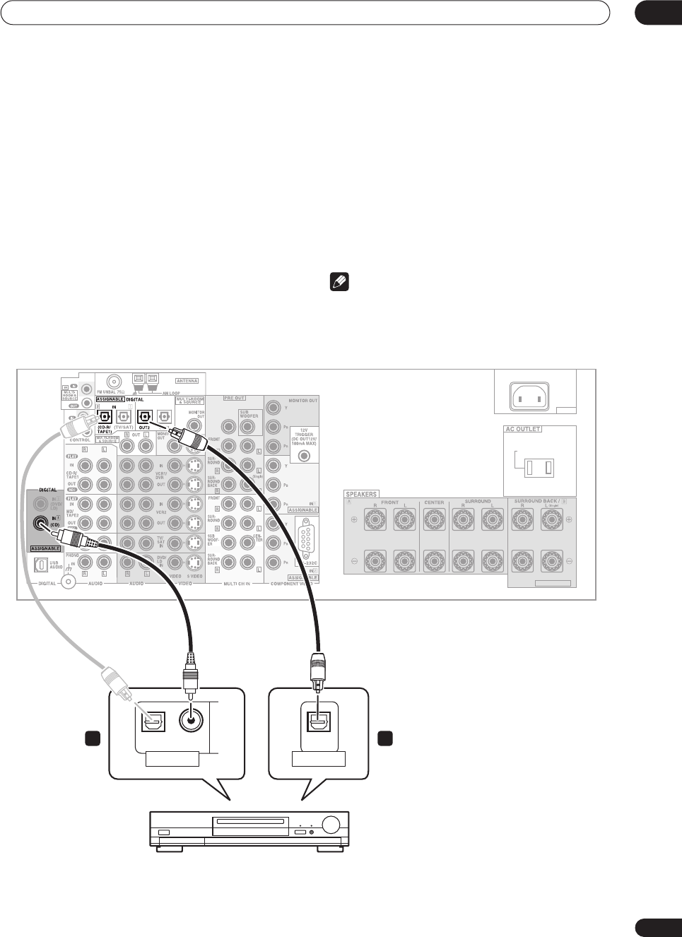
Connecting digital audio sources
This receiver has both digital inputs and outputs,
allowing you to connect digital components for playback
and for making digital recordings. Many digital
components also have analog connections for recording
analog sources (such as a turntable or tape deck). See
Connecting analog audio sources
below for more on this.
1Connect a coaxial digital output on your digital
component to the DIGITAL 4 (CD) input on this
receiver.
• Use a coaxial digital audio cable for the connection.
• If your digital component only has an optical digital
output, you can connect it to one of the optical inputs
on this receiver using an optical cable. When you set
up the receiver you’ll need to tell the receiver which
input you connected the player to (see
Assigning the
digital inputs
on page 75).
• The digital outputs from other components can be
connected to any spare digital audio inputs on this
receiver. You can assign them when setting up the
receiver (see
Assigning the digital inputs
on page 75).
2 Connect one of the DIGITAL outputs on this
receiver to a digital input on the component.
• Use an optical cable to connect to the
DIGITAL
OUT1
or
OUT2
(
OUT2
is shown in the illustration
below).
Note
• In order to record some digital sources, you must
make analog connections as explained in
Connecting
analog audio sources
below.
AC IN
SWITCHED 100W(0.8A)MAX
SELECTABLE
CENTER
OPTICAL COAXIAL
DIGITAL OUT
OPTICAL
DIGITAL IN
CD-R, MD, DAT, etc.
1 2
VSX-9300TX
VSX-9300.book 25 ページ 2004年5月21日 金曜日 午前11時28分
Connecting your equipment
03
26
En
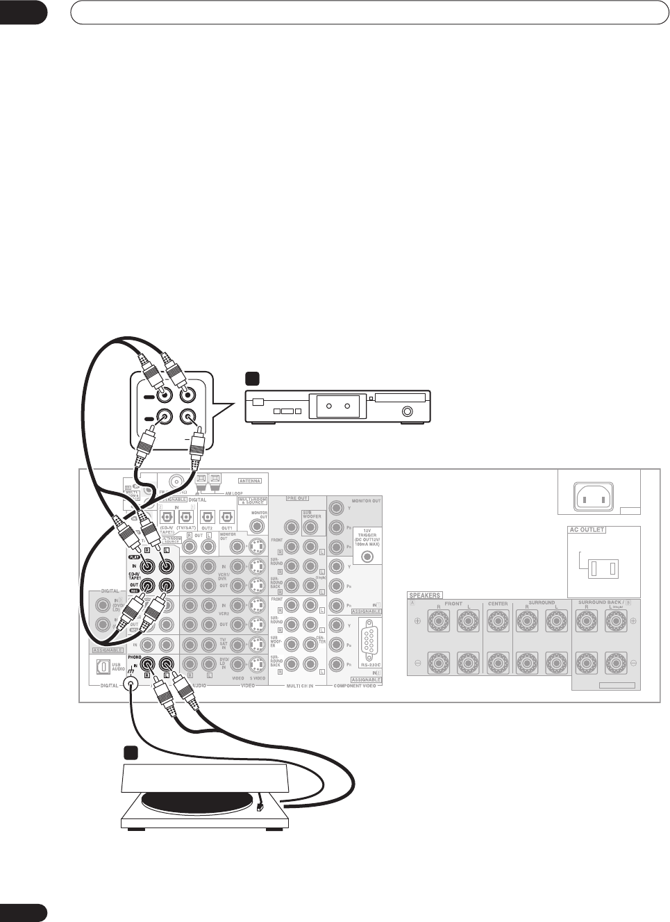
Connecting analog audio sources
This receiver features four stereo audio-only inputs. Two
of these inputs have corresponding outputs for use with
audio recorders.
One of the audio inputs (
PHONO
) is a switchable
turntable input which can also be used for line level
components (see
PHONO/LINE Setup
on page 77 for
more on this). This input also has a grounding terminal
that most turntables require.
1 Connect the analog audio outputs of the source
component to a set of spare audio inputs on this
receiver.
• If you’re connecting a tape deck, MD recorder, etc.,
connect the analog audio outputs (
REC
) to the analog
audio inputs on the recorder.
• Use a stereo RCA phono cable for the connections.
2 Connect the stereo audio outputs of your
turntable to the PHONO inputs on this receiver.
•If your turntable has a grounding wire, secure it to the
ground terminal on this receiver.
•If your turntable has line-level outputs (no grounding
wire), or if you want to connect a different line-level
component, refer to
PHONO/LINE Setup
on page 77
to switch this input to the
LINE
setting.
AC IN
SWITCHED 100W(0.8A)MAX
SELECTABLE
CENTER
AUDIO IN/OUT
PLAY
OUT
IN
REC
RL
2
1
Turntable
VSX-9300TX
Tape deck, etc.
VSX-9300.book 26 ページ 2004年5月21日 金曜日 午前11時28分
Connecting your equipment 03
27
En
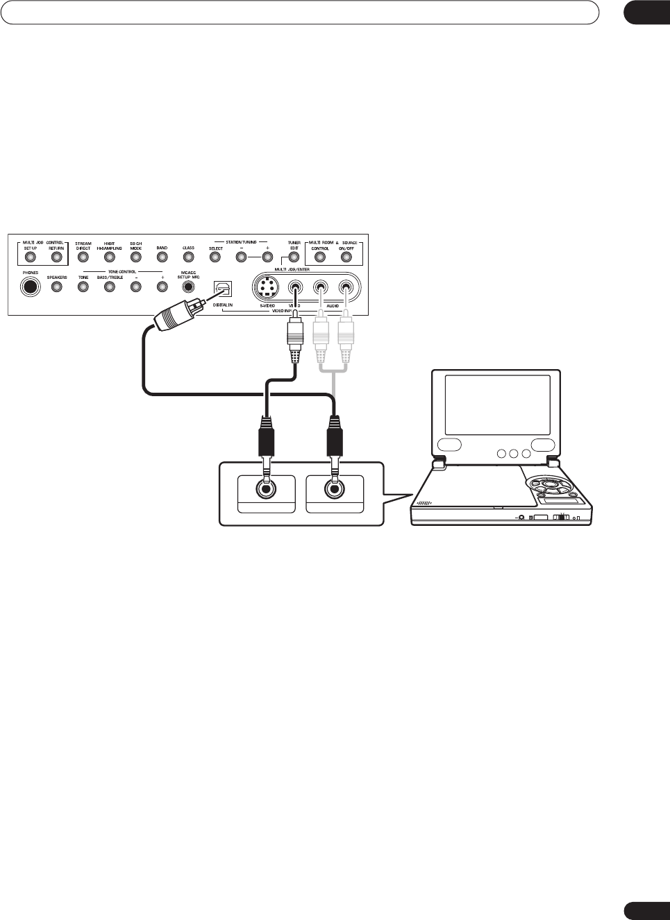
Connecting a component to the front panel inputs
The front panel inputs include a composite video jack
(
VIDEO
), an S-video jack (
S-VIDEO
), stereo analog audio
inputs (
AUDIO L/R
) and an optical digital audio input
(
DIGITAL
). You can use these connections for any kind of
audio/video component, but they are especially
convenient for portable equipment such as camcorders,
video games and portable audio/video equipment.
• The input signals can be accessed by selecting
VIDEO
as the input source.
• Pull down the front cover where indicated to access
the front panel inputs.
•The illustration below shows example connections to
a portable DVD player. Note that you may need a
specialized optical cable for this connection.
VSX-9300TX
DIGITAL OUT (OPTICAL)
PHONES
HOLDON/OFF
COLOR BRIGHT MONITOR
VIDEO IN/OUT
AUDIO IN/OUT
Portable DVD player, etc.
VSX-9300.book 27 ページ 2004年5月21日 金曜日 午前11時28分
Connecting your equipment
03
28
En
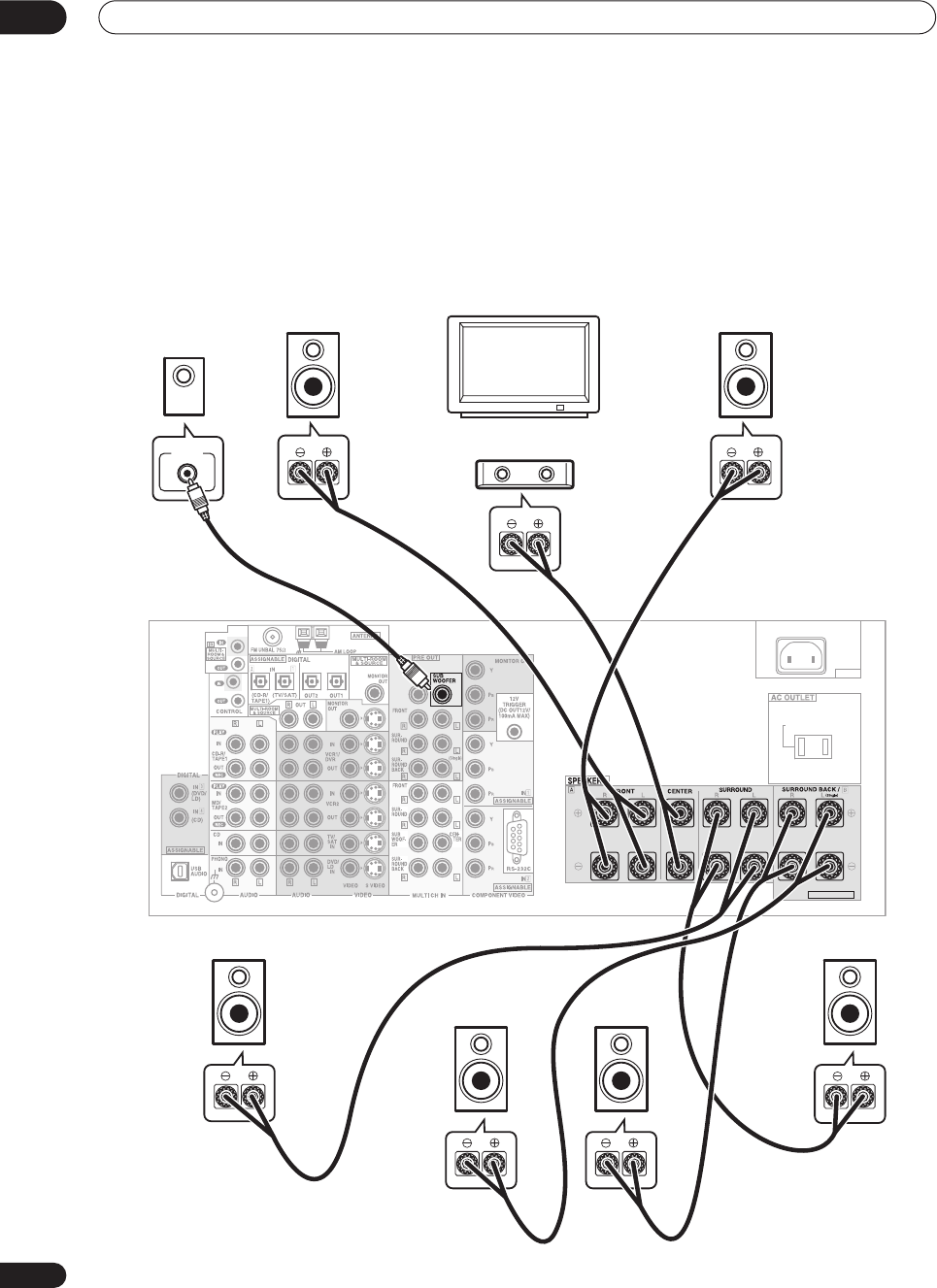
Installing your speaker system
To take full advantage of the receiver’s surround sound
capabilities connect front, center, surround and
surround back speakers, as well as a subwoofer.
Although this is ideal, other configurations with fewer
speakers—no subwoofer or no center speaker, or even
no surround speakers—will work. At the very least, front
left and right speakers only are necessary. Note that your
main surround speakers should always be connected as
a pair, but you can connect just one surround back
speaker if you like (it must be connected to the left
surround back terminal). You can use speakers with a
nominal impedance between 6–16
Ω
(please see
Switching the speaker impedance
on page 64 if you plan
to use speakers with an impedance of less than 8
Ω
).
AC IN
SWITCHED 100W(0.8A)MAX
SELECTABLE
CENTER
VSX-9300TX
Front
left
Front
right
Center
Surround
left
Surround
right
Surround
back right
Surround
back left
LINE LEVEL
INPUT
Subwoofer
TV
VSX-9300.book 28 ページ 2004年5月21日 金曜日 午前11時28分
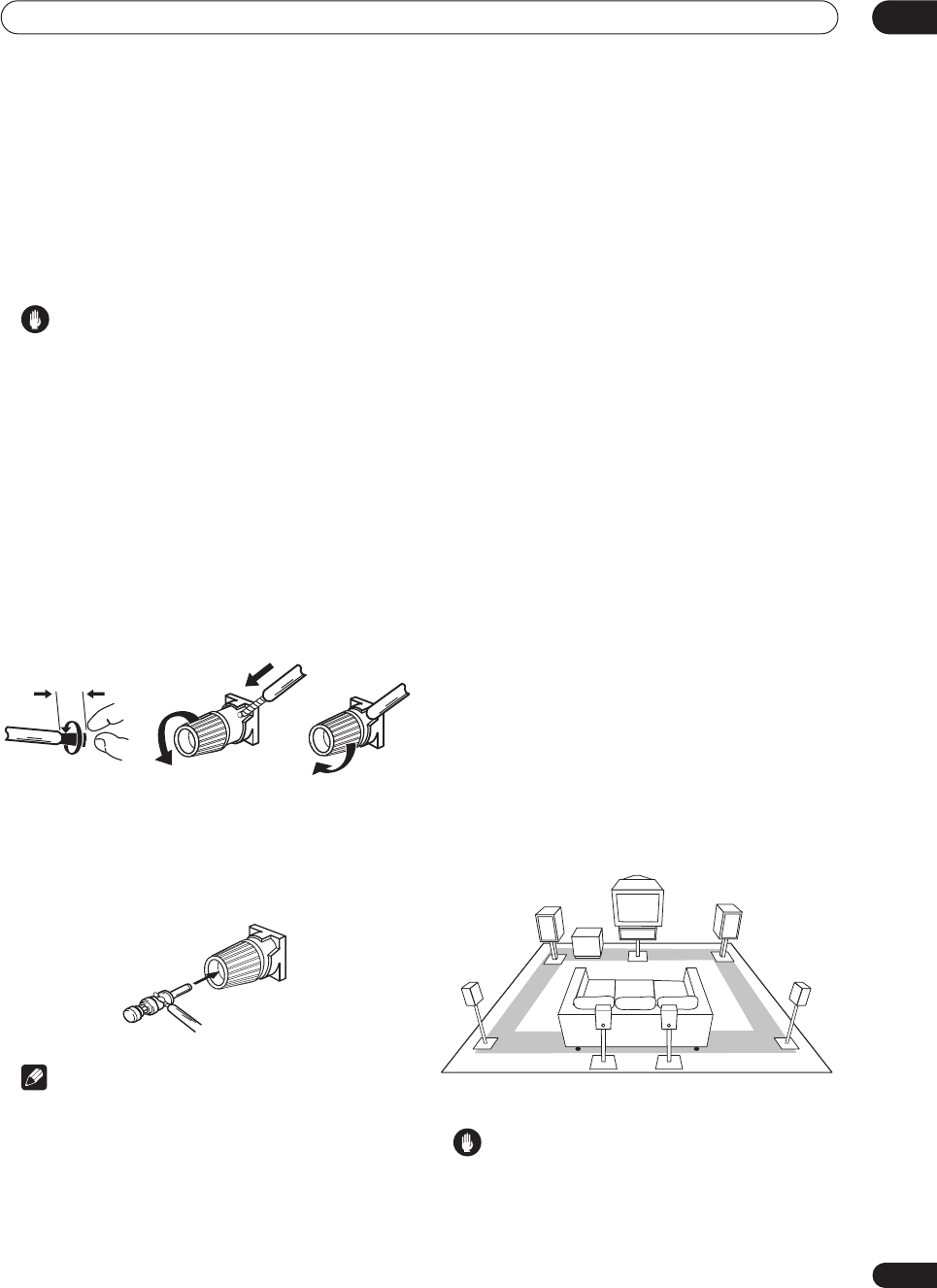
Connecting your equipment 03
29
En
Connecting the speakers
Each speaker connection on the receiver comprises a
positive (+) red, and negative (–) black terminal. For
proper sound you should take care to match these up
with the terminals on the speakers themselves.
• If you only have one surround back speaker, hook it
up to the surround back left (
Single
) terminal.
Caution
• Make sure that all the bare speaker wire is twisted
together and inserted fully into the speaker terminal.
If any of the bare speaker wire touches the back panel
it may cause the power to cut off as a safety measure.
Bare wire connections
Before you start connecting the speakers, make sure that
the speaker cable you’re going to use is properly
prepared with about
3
/
8
in. (10 mm) of insulator stripped
from each wire, and the exposed wire strands twisted
together (
fig. A
).
To connect a terminal, unscrew the terminal a few turns
until there is enough space to insert the exposed wire
(
fig. B
). Once the wire is in position, tighten the terminal
until the wire is firmly clamped (
fig. C
).
Banana plug connections
If you want to use speaker cables terminated with banana
plugs, screw the speaker terminal fully shut then plug the
banana plug into the end of the speaker terminal.
Note
• Please refer to the manual that came with your
speakers for details on how to connect the other end
of the speaker cables to your speakers.
• If you are using a THX certified subwoofer use the
THX INPUT
jack on the subwoofer (if your subwoofer
has one) or switch the filter position to
THX
on your
subwoofer.
•The surround speaker terminals on this receiver can
be connected in a number of ways, depending on
your setup. See
Surround back speaker setting
on
page 51 for an overview of the possible
configurations.
•
Other connections
on page 67 provides greater detail
on alternate speaker setups such as using speaker
system B (page 67), bi-amping (page 68) and bi-
wiring (page 68).
Placing the speakers
Where you put your speakers in the room has a big effect
on the quality of the sound. The following guidelines
should help you to get the best sound from your system.
•The subwoofer can be placed on the floor. Ideally, the
other speakers should be at about ear-level when
you’re listening to them. Putting the speakers on the
floor (except the subwoofer), or mounting them very
high on a wall is not recommended.
• For the best stereo effect, place the front speakers
6–9 ft. apart, at equal distance from the TV.
• Install the center speaker above or below the TV so
that the sound of the center channel is localized at
the TV screen.
•When placing speakers near the TV, use magnetically
shielded speakers to prevent possible interference,
such as discoloration of the picture when the TV is
switched on. If you do not have magnetically shielded
speakers and notice discoloration of the TV picture,
move the speakers farther away from the TV.
• If possible, install the surround speakers slightly
above ear level.
• If you have two surround back speakers THX
recommends placing them together and the same
distance from your listening position.
Caution
• Make sure that all speakers are securely installed.
This not only improves sound quality, but also
reduces the risk of damage or injury resulting from
speakers being knocked over or falling in the event of
external shocks such as earthquakes.
3/8 inch (10mm)
fig. A fig. B fig. C
Front R
Front L
Surround
L
Surround
back R
Surround
R
Sub-
woofer
Center
Surround
back L
VSX-9300.book 29 ページ 2004年5月21日 金曜日 午前11時28分
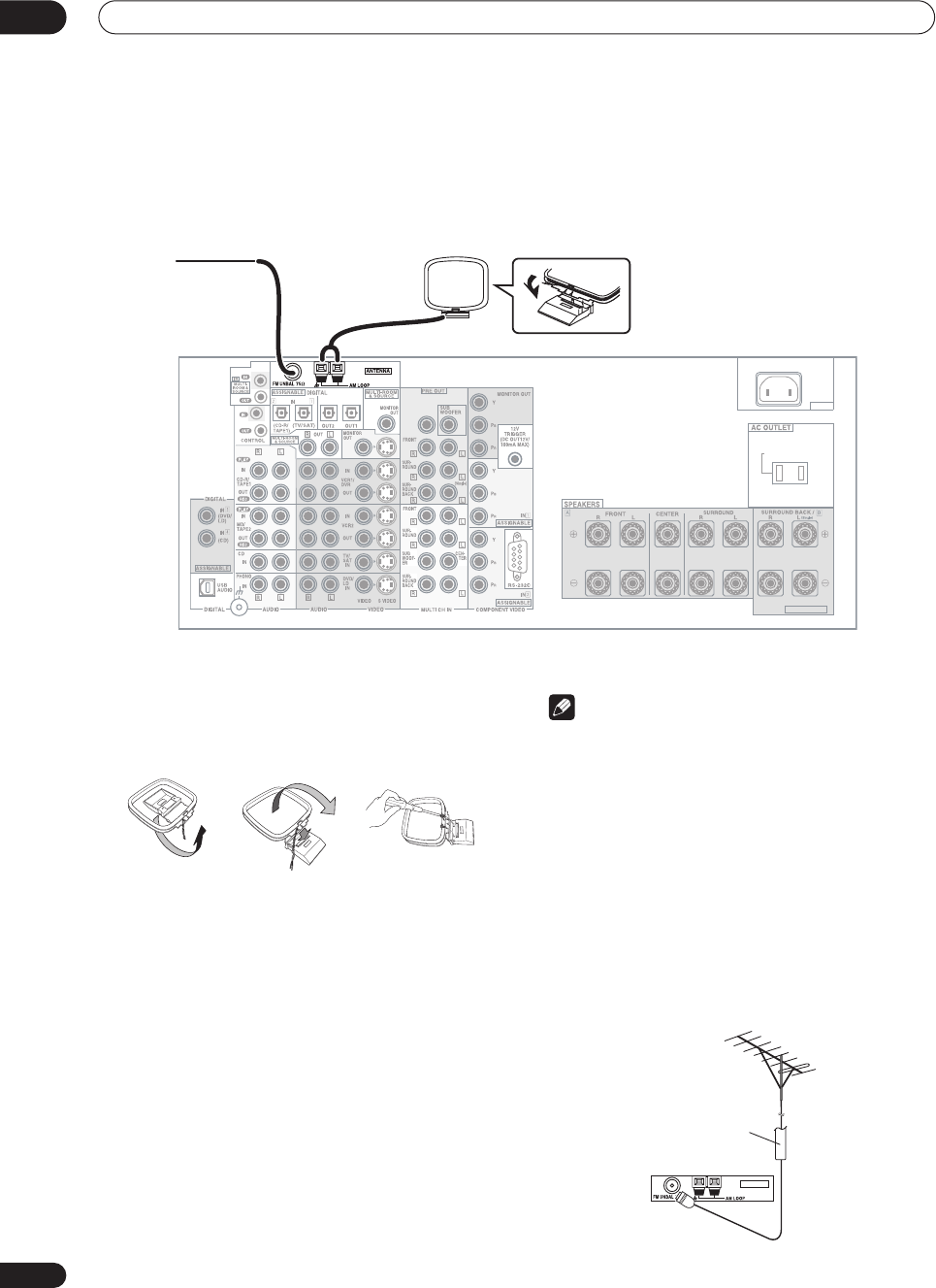
Connecting your equipment
03
30
En
Connecting antennas
The supplied antennas provide a simple way to listen to
AM and FM radio. If you find that reception quality is
poor, an outdoor antenna should give you better sound
quality—see
Connecting external antennas
below.
AM loop antenna
1 Assemble the stand as shown in the illustration.
• Bend the stand in the direction indicated (fig. A).
• Clip the loop into the stand (fig. B).
• It’s possible to fix the AM antenna to a wall (fig. C).
Before fixing, make sure that the reception is
satisfactory.
2 Pull off the protective shields of both AM
antenna wires.
3 Press the AM LOOP antenna terminal tabs to
open and insert one wire into each terminal.
4Release the tabs to secure the AM antenna wires.
5Place the AM antenna on a flat surface and point
in the direction giving the best reception.
Avoid placing near computers, television sets or other
electrical appliances and do not let it come into contact
with metal objects.
Note
• The signal ground (
) is designed to reduce noise
that occurs when an antenna is connected. It is not
an electrical safety ground.
FM wire antenna
• Connect the FM wire antenna to the FM UNBAL
75
Ω
terminal.
For best results, extend the FM antenna fully and fix to a
wall or door frame. Don’t drape loosely or leave coiled up.
Connecting external antennas
To improve FM reception connect an external FM
antenna to the
FM UNBAL 75
Ω
.
AC IN
SWITCHED 100W(0.8A)MAX
SELECTABLE
CENTER
VSX-9300TX
FM wire
antenna
AM loop antenna
fig. A fig. B fig. C
ANTENNA
75Ω coaxial cable
VSX-9300.book 30 ページ 2004年5月21日 金曜日 午前11時28分
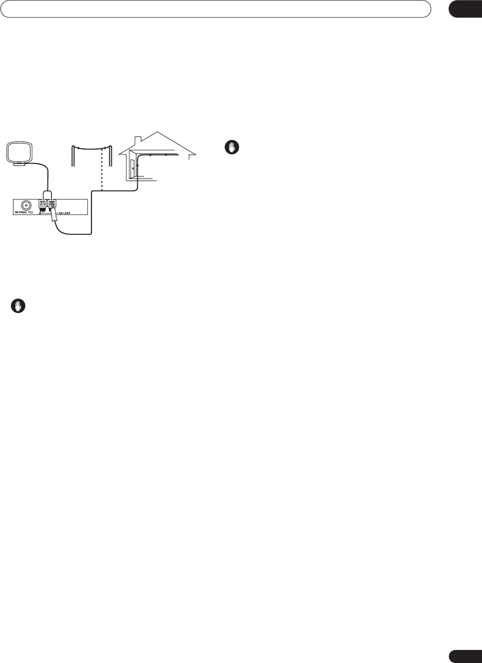
Connecting your equipment 03
31
En
To improve AM reception, connect a 15–18 ft. length of
vinyl-coated wire to the
AM LOOP
terminals without
disconnecting the supplied AM loop antenna.
For the best possible reception, suspend horizontally
outdoors.
Plugging in the
receiver
Only plug in after you have connected all your
components to this receiver, including the speakers.
Caution
• Handle the power cord by the plug part. Do not pull
out the plug by tugging the cord, and never touch the
power cord when your hands are wet, as this could
cause a short circuit or electric shock. Do not place
the unit, a piece of furniture, or other object on the
power cord or pinch the cord in any other way. Never
make a knot in the cord or tie it with other cables. The
power cords should be routed so that they are not
likely to be stepped on. A damaged power cord can
cause a fire or give you an electric shock. Check the
power cord once in a while. If you find it damaged,
ask your nearest Pioneer authorized independent
service company for a replacement.
• Do not use any power cord other than the one
supplied with this unit.
• Do not use the supplied power cord for any purpose
other than that described below.
•The receiver should be disconnected by removing the
mains plug from the wall socket when not in regular
use (for example, when on vacation).
1 Plug the supplied power cord into the AC IN
socket on the back of the receiver.
2 Plug the other end into a power outlet.
About the AC outlet
(Switched 100W max.)
Power supplied through this outlet is turned on and off by
the receiver's
STANDBY/ON
switch. Total electrical
power consumption of connected equipment
should not
exceed 100 W (0.8 A).
Caution
•
Do not connect a TV set
, monitor, heater, or similar
appliance to this unit's AC outlet.
• Do not connect appliances with high power
consumption to the AC outlet in order to avoid
overheating and fire risk. This can also cause the
receiver to malfunction.
• Since a subwoofer can exceed the 100W maximum
when playing sources at a high volume, it is best not
to connect a subwoofer to the AC outlet.
Outdoor antenna
15–18 ft.
Indoor antenna
(vinyl-coated wire)
VSX-9300.book 31 ページ 2004年5月21日 金曜日 午前11時28分
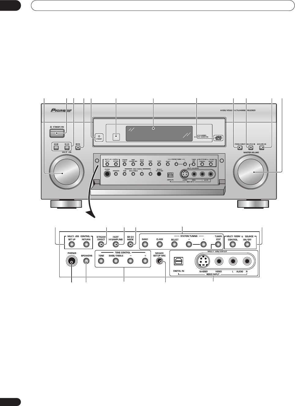
Controls and displays
04
32
En
Chapter 4
Controls and displays
Front panel
1 MULTI JOG dial
Depending on the operation, you can use this to select an
input source or listening mode, as well as for tuner and
system settings. It can often be used instead of the
remote control
/
(cursor up/down) buttons.
2
STANDBY/ON
Press
STANDBY/ON
to switch the receiver on or into
standby.
3 Surround listening mode buttons
(page 37)
Use to select the
MOVIE
and
MUSIC
surround listening
modes.
4 ENTER
Use to confirm your selection (with the
MULTI JOG
dial).
5 STANDBY indicator
Lights when the receiver is in standby.
6 Remote sensor
Receives the signals from the remote control.
7 Display
See
Display
on page 34.
8Advanced MCACC indicator
(page 41)
Lights when Acoustic Calibration EQ is on (Acoustic
Calibration EQ is automatically set to
ALL CH ADJUST
after the Auto Surround Setup has been completed).
9 STEREO/DIRECT
(page 40)
Switches the receiver into
STEREO
mode if it was in a
different listening mode or toggles between
DIRECT
and
STEREO
.
VSX-9300TX
1
13 14 15 17 18
23 5 847
21 22 23
19
16
20
61091112
VSX-9300.book 32 ページ 2004年5月21日 金曜日 午前11時28分

Controls and displays 04
33
En
10 MULTI CH IN
(page 41)
Press to select the component connected to the
MULTI
CH IN
terminals (for example, a DVD-Audio player).
11 ACOUSTIC EQ
(page 41)
Press to select an acoustic calibration EQ setting.
12 MASTER VOLUME dial
Adjusts the volume.
13 MULTI JOG CONTROL
Use the
SET UP
button to access the System Setup
menu, and
RETURN
to exit the current menu screen.
14 STREAM DIRECT
(page 37)
Press to switch on/off Auto playback.
15 HI-BIT/HI-SAMPLING
(page 44)
Use this to switch the audio scaler on or off.
16 SB CH MODE
(page 43)
Use to select the surround/virtual back channel mode.
17 TUNER controls
(page 47)
Use the front panel tuner controls for tuning into stations
and recalling station presets.
BAND
Press to select the AM or FM band.
CLASS
Press repeatedly to switch the preset station classes.
SELECT
Switches between the station memory and frequency
select mode when using the
–
/
+
buttons.
– /+
Selects station memories or frequencies when using
the tuner.
TUNER EDIT
Press to memorize and name a station for recall with
the
MULTI JOG
dial.
18 MULTI ROOM & SOURCE controls
If you’ve made multi-room connections (see
Multi-room
listening
on page 69) use these controls to control the
sub room from the main room (see
Using the multi-room
controls
on page 70).
CONTROL
Use together with the
MULTI JOG
dial to select the
function or use with the
MASTER VOLUME
to select
the volume of the sub room.
ON/OFF
Use to switch the multi-room feature on or off.
19 PHONES jack
(page 40)
Use to connect headphones (no sound will be heard
through the speakers).
20 SPEAKERS
(page 67)
Depending on the surround back speaker setting
(page 51), press either to switch the speaker system or
simply to switch it off (See
Switching the speaker system
on page 67 for more on this).
21 TONE CONTROL
(page 45)
TONE
Press to switch the tone controls on or off (bypass).
BASS/TREBLE
Use to select whether the bass or treble will be
adjusted.
+/–
Use to adjust the frequency setting.
22 MCACC SETUP MIC jack
Use to connect the supplied microphone.
23 VIDEO INPUT jacks
(page 27)
•
DIGITAL IN
– Connect a game console, portable DVD
player, video camera (etc.), that has an optical digital
connection.
•
S-VIDEO
– Connect a video camera (etc.), that has an
S-video out.
•
VIDEO / AUDIO (L/R)
– Connect a video camera, etc.
that has standard RCA video/audio outputs.
VSX-9300.book 33 ページ 2004年5月21日 金曜日 午前11時28分
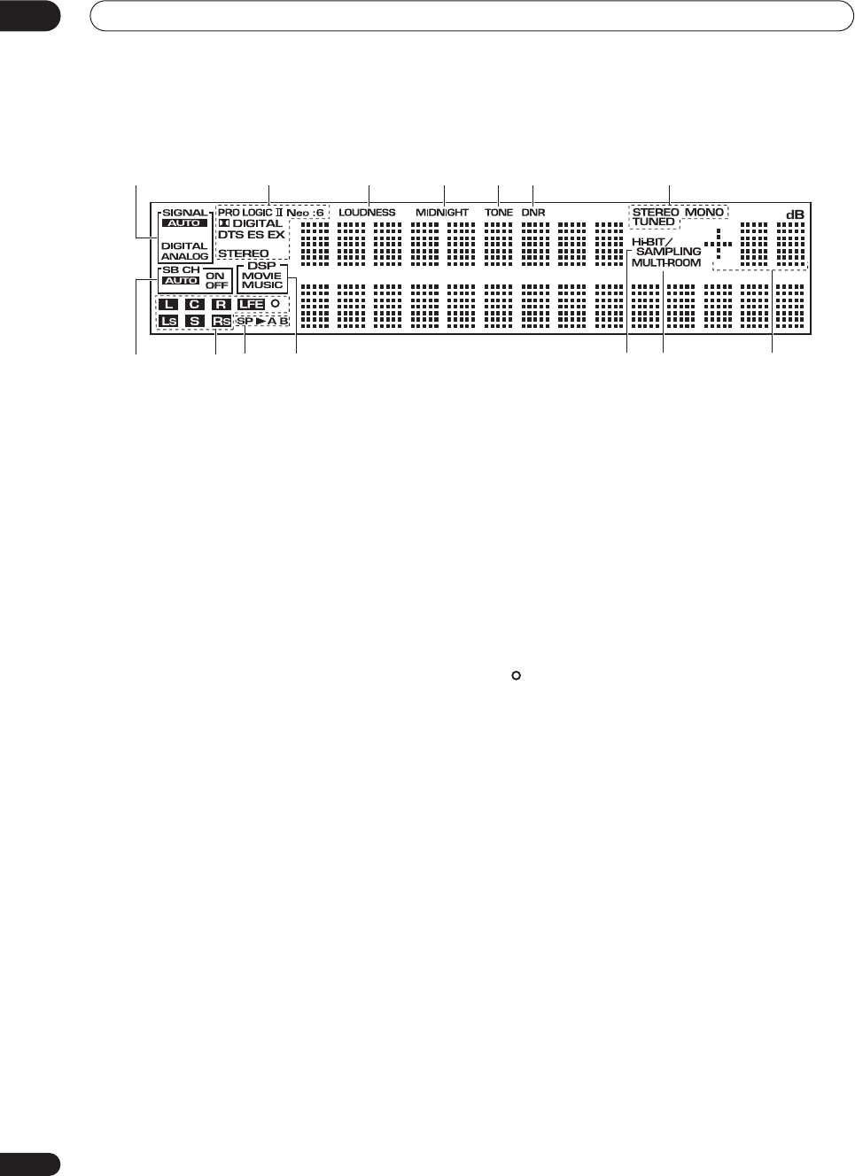
Controls and displays
04
34
En
Display
1 SIGNAL indicators
(page 42)
Light to indicate the currently selected input signal.
AUTO
lights when the receiver is set to select the input
signal automatically.
2 Digital format indicators
•
PRO LOGIC II
– Lights during Dolby Pro Logic II and
Pro Logic IIx processing.
•
Neo:6
– Lights during Neo:6 processing with 2-
channel sources.
•
2
DIGITAL
– Lights when a Dolby Digital signal is
detected.
•
DTS
– Lights when a DTS signal is detected.
•
ES
– Lights when a DTS-ES signal is detected.
•
EX
– Lights when a Dolby Digital EX signal is
detected.
•
STEREO
– Lights during 2-channel playback.
3 LOUDNESS
(page 45)
Lights when Loudness listening is active.
4 MIDNIGHT
(page 45)
Lights when Midnight listening is active.
5 TONE
(page 45)
Lights when the tone control is switched on.
6 DNR
(page 46)
Lights when digital noise reduction is switched on.
7 Tuner indicators
STEREO
(page 47)
Lights when listening to a stereo FM broadcast in
auto/stereo mode.
MONO
(page 48)
Lights when the tuner MPX mode is set to mono.
TUNED
Lights when tuned to a broadcast.
8 SB CH
(page 43)
Indicates the surround back channel (or Virtual Surround
Back) setting (
AUTO
,
ON
or
OFF
).
9 Program format indicators
These change according to which channels are active in
Dolby, DTS, DVD-A and SACD sources.
LS
,
S
and
RS
will light at the same time to indicate 6.1
channel sources.
•
L
– Left front channel
•
C
– Center channel
•
R
– Right front channel
•
LS
– Left surround channel
•
S
– Surround channel (mono)or surround back
channel
•
RS
– Right surround channel
•
LFE
– Low frequency effects channel
• – Lights when an LFE signal is detected
10 Speaker indicators
(page 67)
Lights to indicate the current speaker system,
A
and/or
B
.
11 Listening mode indicators
(page 37)
Shows
MOVIE
or
MUSIC
when a surround listening
mode is selected.
DSP
will light with a box around it when
one of the advanced (DSP) listening modes is selected.
12 Hi-BIT/SAMPLING
(page 44)
Lights when the audio scaler is switched on.
13 MULTI-ROOM
(page 69)
Lights when the multi room feature is active.
14 Volume level indicator
1235
8
476
91110 12 13 14
VSX-9300.book 34 ページ 2004年5月21日 金曜日 午前11時28分
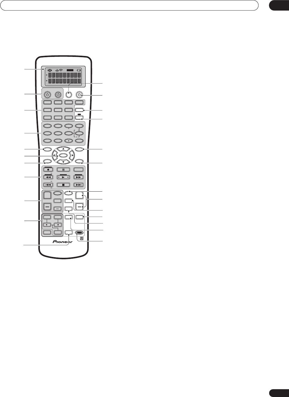
Controls and displays 04
35
En
Remote control
1 Remote Control Display Screen
2 SOURCE
Use this button to turn on/off other components. You
must input the component preset code in order to do
this (see
Using the remote control with other
components
on page 54).
TV
This is a dedicated TV button. Use it to turn on/ off
your TV.
3 MULTI CONTROL buttons
These buttons are the basic controls that switch the
mode of the receiver and the remote control, which
allows you to control your other components.
TV CONT
Press so that the remote control can operate the TV
control commands.
4 Number buttons
The operation of these buttons depends on whether the
remote control has been set to the
RECEIVER
or
MULTI
CONTROL
setting (see
Controlling other equipment
on
page 54 for more on this). When
RECEIVER
is selected,
you’ll be able to select the following:
DIMMER
(page 63)
Use to adjust the brightness of the front panel
display.
LOUDNESS
(page 45)
Press to switch Loudness on/off.
TONE
(page 45)
Press to switch the tone controls on or off (bypass).
BASS/TREBLE
(page 45)
Use to select whether the bass or treble will be
adjusted.
+/–
Use to adjust the sound delay, the tone, effect and
channel levels, as well as to change Dolby Pro Logic
II / Dolby Pro Logic IIx Music parameter settings.
EFFECT/CH SEL
Press repeatedly to select a channel, then use
–/+
to
adjust the level (see
Tip
on page 53). Also selects the
EFFECT
mode, Dolby Pro Logic II / Dolby Pro Logic IIx
Music parameters (see page 39) and the sound delay
setting (see page 62). You can then use the
+
and
–
buttons to make these adjustments.
SIGNAL SEL
(page 42)
Press repeatedly to select one of the following:
• AUTO
If there are analog and digital signals input, the
receiver automatically selects the digital signal.
• DIGITAL
Selects an optical or coaxial digital signal.
• ANALOG
Selects an analog signal.
DNR
Press to switch digital noise reduction on/off (see
Reducing noise during playback
on page 46).
VIDEO SEL
(page 63)
Press repeatedly to select the video source.
HI-BIT
(page 44)
Use this to switch the audio scaler on or off.
5 SYSTEM SETUP
Use to display the System Setup menu (page 74). Also
used to display a menu when controlling other
components (such as a DVD player or TV), or as the
TUNER EDIT
button when using the tuner.
SETUP
SOURCE
DVD/LD
VCR2
DIMMER
LOUDNESS TONE
SIGNAL SEL
DNR
DISC
1
5
90
678
342
BASS/TREBLE
VIDEO SEL
HI-BIT
DIRECT ACCESS
SEARCH MODE
ENTER
GUIDE
SYSTEM SETUP
TUNER EDIT
MPX
TUNING BAND
DTV ON/OFF DISP MODE
TUNING
STATION
TV VOL
MOVIE MUSIC MUTE
ENTER
SURROUND
REMOTE
SETUP
MODE
DTV MENU CLASS
TV CONTROL
TV CH
TV INPUT
INPUT
MIDNIGHT
MULTI DH
INPUT
ACOUSTIC
EQ
SB CH
MODE
STEREO/
DIRECT
STATION
VOLUME
CHANNEL
SUB TITLE
ENTER
TOP MENU
MENU
AUDIO
RETURN
TRACK
EXIT
+
10
+
+
++
+
+
CHANNEL
+
EFFECT/CH SEL
VIDEO CD
TV/SAT
TV CONT
MULTI CONTROL
VCR1 /
DVR
CD-R/
TAPE1
MD/
TAPE2
MULTI
OPERATION
SYSTEM
OFF
RECEIVERTV
TUNER
RECEIVER
1
1
2
13
1
4
1
5
1
6
1
7
1
8
1
9
2
0
21
2
2
23
2
4
2
3
4
5
6
7
8
9
10
11
VSX-9300.book 35 ページ 2004年5月21日 金曜日 午前11時28分

Controls and displays
04
36
En
6
/
/
/
/ENTER buttons
Use to navigate menus and select options/execute
commands.
7 AUDIO
Use to switch the audio tracks of a DVD when a DVD
player is selected as the input source.
8 Command buttons for other components
Use these buttons to control the component you selected
with the
MULTI CONTROL
buttons. The are available
once you’ve programmed the remote to control the
appropriate component (for example, your TV or DVD
player). See
Controlling other equipment
on page 54 for
more on this.
9 TV CONTROL buttons
These are dedicated buttons used to control your TV once
you’ve programmed your TV preset code (see
Controlling
other equipment
on page 54 for more on this).
TV INPUT
Press to select the input source for the TV.
TV CH +/-
Use these buttons to change the channel of the TV.
TV VOL +/-
Press to control the volume of the TV.
10 Listening mode buttons
(page 37)
MOVIE / MUSIC
Press to select the surround listening mode you want
(see
Listening in surround sound
on page 37).
After selecting a
MOVIE
or
MUSIC
listening mode
above, use these to select the options available.
ENTER
Use to confirm your selection.
STEREO/DIRECT
(page 40)
Switches the receiver into
STEREO
mode if it was in
a different listening mode or toggles between
DIRECT
and
STEREO
.
11 SB CH MODE
(page 43)
Use to select the surround/virtual back channel mode.
12 SYSTEM OFF
(page 59)
Press to switch off all Pioneer components in your
system, or any other component you have also
programmed to switch off using the System Off function.
13
RECEIVER (STANDBY/ON)
Press to switch the receiver on or into standby.
14 MULTI OPERATION
(page 59)
Use this button to perform multi operations.
15 RECEIVER
Press this button to access receiver functions or when
setting up the receiver.
16 TOP MENU/GUIDE
Use to display the disc ‘top menu’ when a DVD player is
selected as the input source. Also use to find stations or
menus on a digital TV tuner.
17 RETURN
When you are setting up the receiver, this button will take
you back one step. When another component is selected
(such as a DVD player, cable tuner, satellite tuner or
digital TV tuner), use it the same way as the components
‘Return’ button (it may also exit from the menu screen,
depending on the maker of the unit).
18 INPUT
Press to select an input source. The button will cycle
through all the possible input sources (such as
DVD/LD
,
USB
and
PHONO
).
19 VOLUME (+/-)
Use to increase or decrease the volume of the receiver.
20 MIDNIGHT
(page 45)
Press to switch on/off Midnight listening.
21 MUTE
Press to mute or restore the volume.
22 MULTI CH INPUT
(page 41)
Press to select the component connected to the
MULTI
CH IN
terminals (for example, a DVD-Audio player).
23 ACOUSTIC EQ
(page 41)
Press to select an acoustic calibration EQ setting.
24 REMOTE SETUP
Use to customize remote control functions and the
remote control display (see
Controlling other equipment
on page 54 for more on this).
VSX-9300.book 36 ページ 2004年5月21日 金曜日 午前11時28分
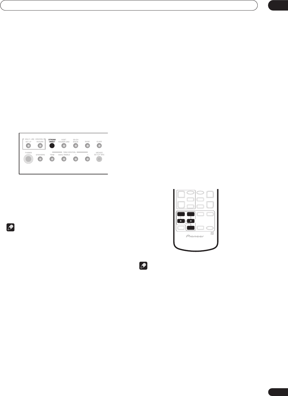
Listening to your system 05
37
En
Chapter 5
Listening to your system
Auto playback
• Default setting:
On
There are many ways to listen back to sources using this
receiver, but for the simplest, most direct listening option
is the Stream Direct feature. With this, the receiver
automatically detects what kind of source you’re playing
and selects multichannel or stereo playback as
necessary.
• While listening to a source, press STREAM
DIRECT on the front panel to switch it on or off.
The decoding or playback format shows briefly in the
display before showing
STREAM DIRECT
. Check the
digital format indicators in the front panel display to see
how the source is being processed.
Note
• Stereo surround (matrix) formats are decoded
accordingly using
NEO:6 CINEMA
or
2
Pro Logic
IIx MOVIE
(see
Listening in surround sound
below for
more on these decoding formats).
•The Stream Direct feature is canceled if you connect
headphones or select the multichannel analog
inputs.
Listening in surround sound
Using this receiver, you can listen to any source in
surround sound. However, the listening mode options
and the current active mode may change depending on
your speaker setup, the
SB CH
mode setting, and the type
of source you’re listening to.
• If you connected surround back speakers, see also
Using the surround back channel
on page 43 for more
on the
SB CH
mode setting.
• While listening to a source, press MOVIE or
MUSIC and
/
(cursor left/right) to select a
listening mode, then press ENTER.
You can also use the front panel
MUSIC
and
MOVIE
buttons instead of the remote control to select listening
modes. After selecting the mode you want, simply turn
the
MULTI JOG
dial to cycle through the available
options, pressing
ENTER
to select a mode.
Note
• If the
SB CH MODE
(page 43) is switched to
OFF
, or
the surround back speakers are set to
NO
(this
happens automatically if the
Surround back speaker
setting
on page 51 is set to anything but
Normal
System
),
2
Pro Logic IIx
(below) becomes
2
Pro
Logic II
(5.1 channel sound).
•When the Virtual Surround Back mode (page 44) is
switched on,
+VSB
will show in the front panel
display after modes which are using this feature.
• In modes that give 6.1 channel sound, the same
signal is heard from both surround back speakers.
• You can’t use the
MUSIC
and
MOVIE
modes with
sources over 48kHz when using one of the digital
inputs.
MOVIE MUSIC
ENTER
SURROUND
MODE
VSX-9300.book 37 ページ 2004年5月21日 金曜日 午前11時28分
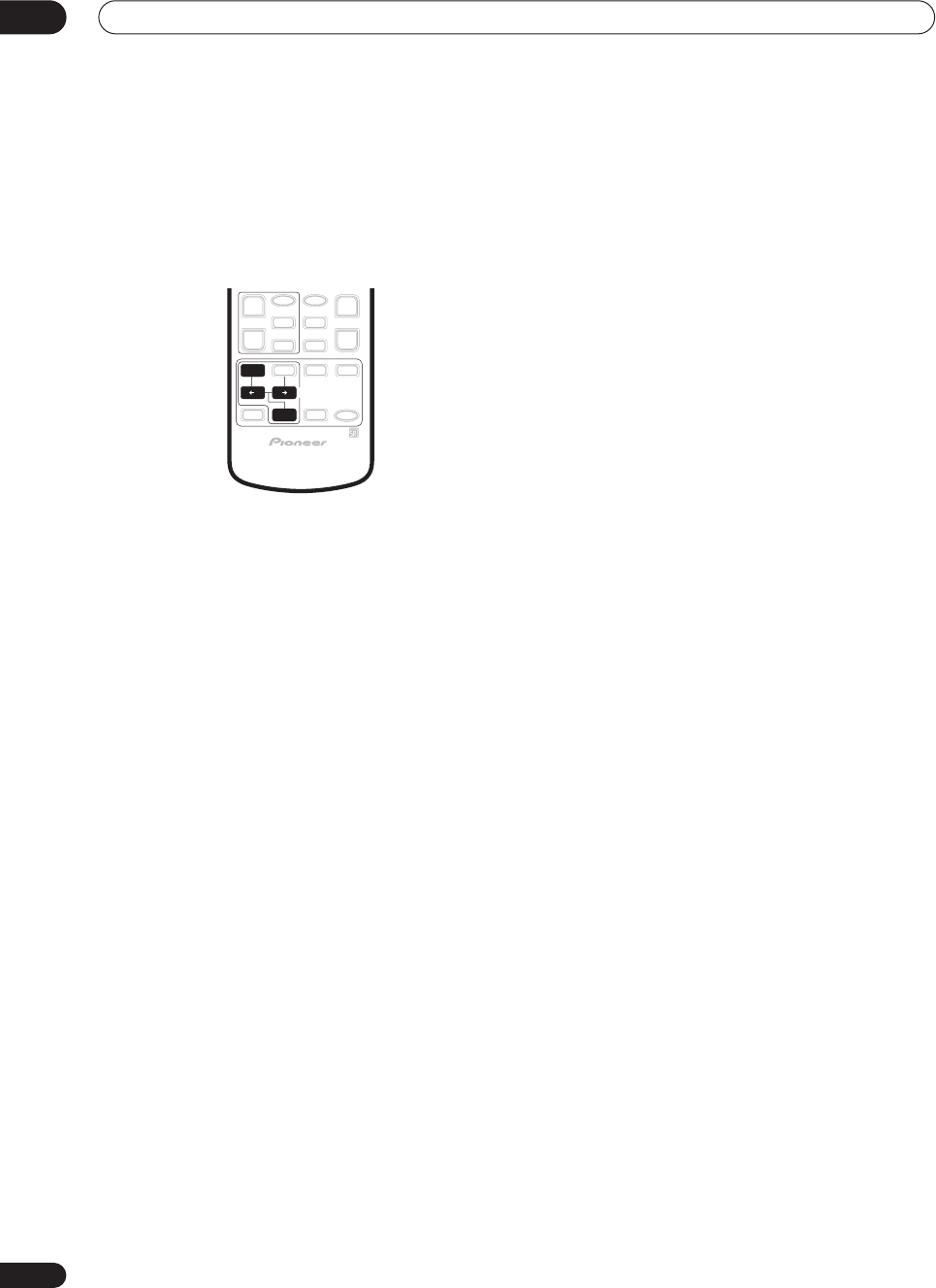
Listening to your system
05
38
En
The MOVIE listening modes
These modes are specifically designed for watching
movies. The basic modes provide pure decoding of
multichannel sources, and will create surround channels
for two channel sources. The advanced effect modes
have been created give you different kinds of surround
sound environments when listening to any source.
Basic modes
•
THX CINEMA
– Gives you cinema-quality sound from
your home theater system using all the speakers in
your setup (for both multichannel
and
two channel
sources)
With multichannel sources
(such as DVDs and digital
satellite broadcasts), the
2
DIGITAL
or
DTS
indicator on
the front panel lights depending on the source format.
With two channel sources
, select from:
•
2
Pro Logic IIx MOVIE
– Up to 7.1 channel sound,
especially suited to movie sources
•
2
PRO LOGIC
– 4.1 channel surround sound with
sound from the surround speakers in mono
•
NEO:6 CINEMA
– 6.1 channel sound, especially
suited to movie sources
With multichannel sources, if you have connected
surround back speaker(s) and have selected
SB CH MODE
ON
, you can select (according to format):
•
THX SURROUND EX
– Allows you to hear 6.1 or 7.1
channel playback with Dolby 5.1 channel sources
•
2
Pro Logic IIx MOVIE+THX
– Up to 7.1 channel
sound, especially suited to Dolby multichannel movie
sources
•
Dolby Digital EX
– Creates surround back channel
sound for 5.1 channel sources and provides pure
decoding for 6.1 channel sources (like Dolby Digital
Surround EX)
•
2
Pro Logic IIx MOVIE
– See above
•
DTS+Neo:6
– Allows you to hear 6.1 or 7.1 channel
playback with DTS 5.1 encoded sources
•
DTS+Neo:6+THX
– Up to 7.1 channel sound,
especially suited to DTS multichannel movie sources
•
DTS-ES
– Allows you to hear 6.1 or 7.1 channel
playback with DTS-ES encoded sources (depending
on the disc,
DISC 6.1
or
MTRX 6.1
may be displayed)
•
DTS-ES+THX
– Up to 7.1 channel sound with DTS-ES
encoded sources, especially suited to multichannel
movie sources
Advanced effect modes
•
ACTION
– Designed for action movies with dynamic
soundtracks
•
SCI-FI
– Designed for science fiction with lots of
special effects
•
DRAMA
– Designed for movies with lots of dialog
•
MUSICAL
– Creates a concert hall-type sound for
musicals
•
MONOFILM
– Creates surround sound from mono
soundtracks
•
5/7-D THEATER
– Creates an extra wide stereo field
MOVIE
ENTER
SURROUND
MODE
VSX-9300.book 38 ページ 2004年5月21日 金曜日 午前11時28分
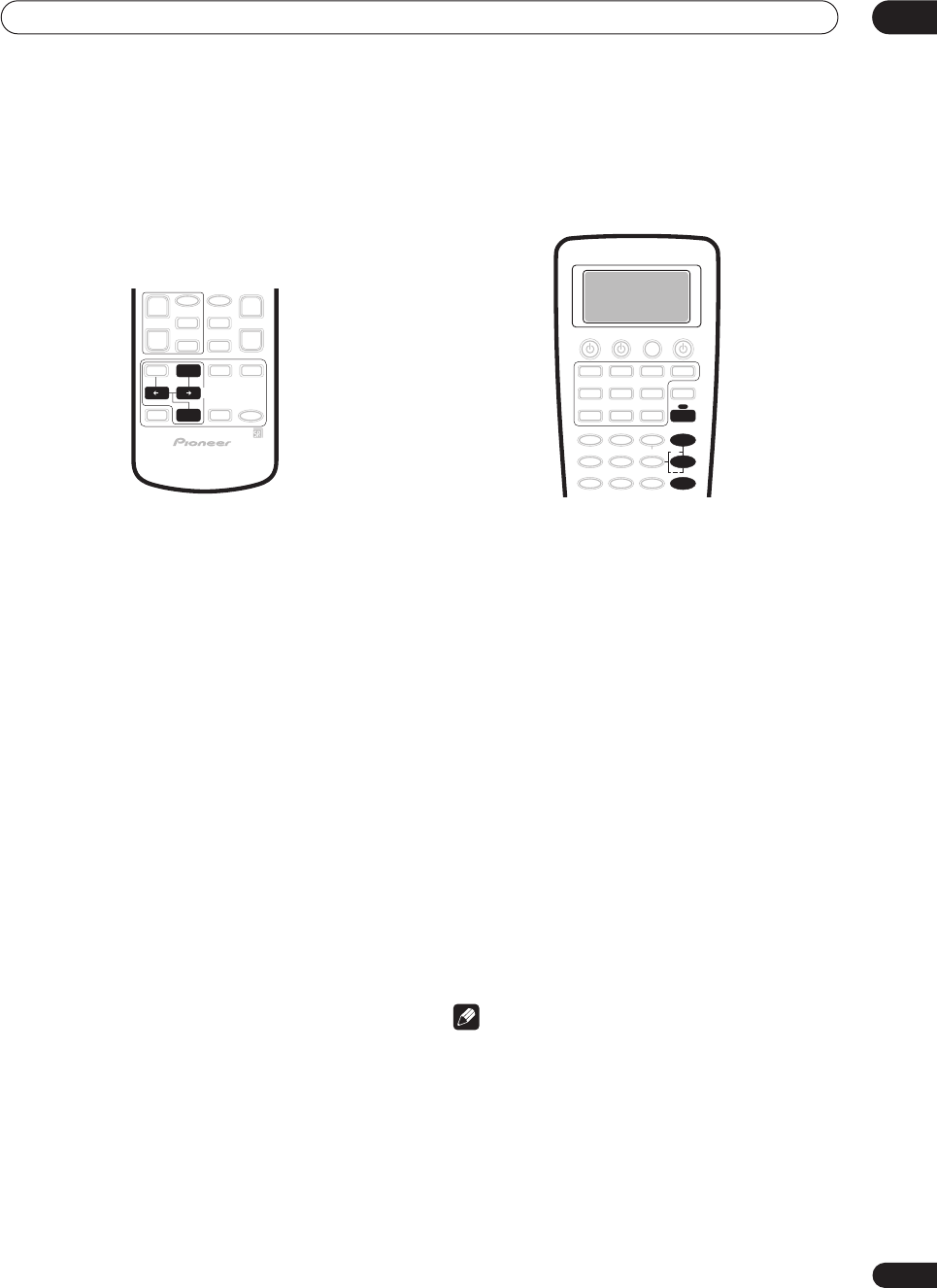
Listening to your system 05
39
En
The MUSIC listening modes
These modes are specifically designed for listening to
music. The basic modes provide pure decoding of
multichannel sources, and will create surround channels
for two channel sources. The advanced effect modes
have been created give you different kinds of surround
sound environments when listening to any source.
Basic modes
With multichannel sources
(such as DVDs and digital
satellite broadcasts), the
2
DIGITAL
or
DTS
indicator on
the front panel lights depending on the source format.
With two channel sources
, select from:
•
2
Pro Logic IIx MUSIC
– Up to 7.1 channel sound,
especially suited to music sources
•
NEO:6 MUSIC
– 6.1 channel sound, especially suited
to music sources
With multichannel sources, if you have connected
surround back speaker(s) and have selected
SB CH MODE
ON
, you can select (according to format):
•
Dolby Digital EX
– Creates surround back channel
sound for Dolby 5.1 channel sources and provides
pure decoding for 6.1 channel sources (like Dolby
Digital Surround EX)
•
2
Pro Logic IIx MUSIC
– See above
•
DTS+Neo:6
– Creates surround back channel sound
for DTS 5.1 channel sources
•
DTS-ES
– Provides pure decoding of DTS-ES encoded
sources (depending on the disc,
DISC 6.1
or
MTRX
6.1
may be displayed)
Advanced effect modes
•
CLASSICAL
– Gives a large concert hall-type sound
•
CHAMBER
– Creates a space with a lot of reverb
•
JAZZ
– Creates the sound of a small jazz club
•
ROCK
– Creates a live concert sound for rock music
•
DANCE
– Designed for music with lots of bass
•
5/7CH STEREO
– Allows you to hear stereo sources
from all the speakers in your setup
Dolby Pro Logic IIx Music settings
When listening to 2-channel sources in Dolby Pro Logic
IIx Music mode, there are three further parameters you
can adjust: Center Width, Dimension, and Panorama.
1Press RECEIVER.
2With ‘
2
Pro Logic IIx MUSIC’ mode active, press
EFFECT/CH SEL repeatedly to select CENTER WIDTH,
DIMENSION or PANORAMA.
•
CENTER WIDTH
– Provides a better blend of the front
speakers by spreading the center channel between
the front right and left speakers, making it sound
wider (higher settings) or narrower (lower settings).
(This is only available when using a center speaker.)
•
DIMENSION
– Adjusts the depth of the surround
sound balance from front to back, making the sound
more distant (minus settings), or more forward
(positive settings).
•
PANORAMA
– Extends the front stereo image to
include the surround speakers for a ‘wraparound’
effect.
3 Use the +/– buttons to adjust the setting.
Center Width is adjustable between
0
and
7
(default :
3
);
Dimension between
–3
and
+3
(default :
0
); Panorama is
ON
or
OFF
(default :
OFF
).
4 Press EFFECT/CH SEL again to adjust other
settings.
Note
•If the
SB CH MODE
is switched to
OFF
,
2
Pro Logic
IIx
(above) becomes
2
Pro Logic II
(5.1 channel
sound), however the above setting will still be
effective.
• If you set the
CENTER WIDTH
to
7
, all the center
channel signal goes to your front speakers, creating
a ‘phantom’ center channel.
MUSIC
ENTER
SURROUND
MODE
+
EFFECT/CH SEL
RECEIVER
VSX-9300.book 39 ページ 2004年5月21日 金曜日 午前11時28分
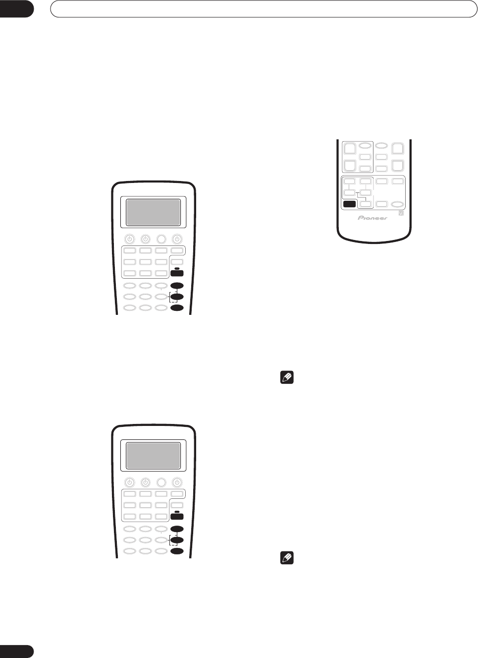
Listening to your system
05
40
En
Neo:6 Music settings
• Default setting:
2
When listening to 2-channel sources in Neo:6 Music
mode, you can adjust the center image to create a wider
stereo effect with vocals. Note that this is only available
when using a center speaker.
1Press RECEIVER.
2With NEO:6 MUSIC mode active, press EFFECT/CH
SEL repeatedly to select CENTER IMAGE.
3 Use the +/– buttons to adjust the setting.
Adjust the effect from
0
(no effect) to
5
(most prominence
given to the center channel).
Adjusting the advanced effect level
• Default setting:
50
(except
5/7CH STEREO
:
90
)
You can emphasize or reduce the level of the advanced
effects as you like. You can set the effect level
independently for each mode.
1Press RECEIVER.
2 With one of the advanced effect modes active,
press EFFECT/CH SEL repeatedly until EFFECT shows
in the front panel display.
3 Use the +/– buttons to adjust the effect level.
The effect level can be adjusted from
10
(min) to
90
(max).
Listening in stereo
When you select
STEREO
or
DIRECT
, you will hear the
source through just the front left and right speakers (and
possibly your subwoofer depending on your speaker
settings). Dolby Digital and DTS multichannel sources
are downmixed to stereo.
•While listening to a source, press STEREO/DIRECT
for stereo playback.
Press repeatedly to switch between:
•
STEREO
– The audio is heard with your surround
settings (such as channel level) and you can still use
digital processing (such as the Midnight, Loudness,
and Tone control functions).
•
DIRECT
– Bypass all effects and surround settings so
that the audio remains as close to the source audio
signal as possible.
Note
• If you switch on any signal processing features (for
example, digital noise reduction or the tone controls)
when
DIRECT
is selected, the receiver automatically
switches to
STEREO
.
Listening with headphones
When headphones are connected, all multichannel
sources, as well as all of the
MOVIE
and
MUSIC
modes
with be downmixed to 2 channels. Two channel sources
will be heard in stereo.
• Connect a pair of headphones to the PHONES
jack on the front panel.
All sources will be heard in stereo (downmixed). When
you disconnect them it reverts to the previous mode.
Note
•Many receiver features (such as matrix decoding) are
not accessible when the headphones are connected.
•When headphones are connected, no sound is heard
from the speakers. However, sound will still be output
from the preouts.
• You can only hear the front left and right channels
when
MULTI CH IN
is switched on.
+
EFFECT/CH SEL
RECEIVER
+
EFFECT/CH SEL
RECEIVER
STEREO/
DIRECT
VSX-9300.book 40 ページ 2004年5月21日 金曜日 午前11時28分
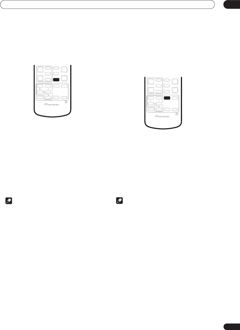
Listening to your system 05
41
En
Using the multichannel analog inputs
If you’ve connected to the multichannel inputs on the
rear panel (see
Connecting the multichannel analog
outputs
on page 20), you will be able to select them as
your input source.
1 Make sure you have set the playback source to
the proper output setting.
For example, you might need to set your DVD player to
output multichannel analog audio.
2Press MULTI CH INPUT (MULTI CH IN on the front
panel) to select the multichannel analog inputs.
MULTI CH IN
shows in the display to indicate the audio
is coming from the multichannel analog inputs,
regardless of the input source selected. The input source
remains dedicated to the multichannel inputs until you
press
MULTI CH IN
/
MULTI CH INPUT
again to cancel.
• If you need to set the channel levels, see
Channel
Level
on page 52 to do so.
Note
• You can’t use any signal processing features (for
example, the
MOVIE
or
MUSIC
modes or the tone
controls) with the multichannel analog inputs.
• Any speakers set to
NO
in the
Speaker Setting
on
page 51 do not output the audio for the
corresponding channel.
• You can’t use the Second Zone speaker B setup
(page 67) with the multichannel analog inputs.
Listening with Acoustic Calibration
EQ
You can listen to sources using the Acoustic Calibration
Equalization set in
Automatically setting up for surround
sound
on page 12 or
Acoustic Calibration EQ
on page 81.
Refer to these pages for more on Acoustic Calibration
Equalization.
• While listening to a source, press ACOUSTIC EQ.
Press repeatedly to select between:
•
ALL CH ADJUST
– No special weighting is given to
any one channel.
•
FRONT ALIGN
– All speakers are heard in
accordance with the front speaker settings.
•
CUSTOM 1/2
– Custom settings
•
OFF
– Switches Acoustic Calibration EQ off.
The MCACC indicator on the front panel lights when
Acoustic Calibration EQ is active.
Note
• You can’t use Acoustic Calibration EQ when
MULTI
CH IN
is switched on.
• If you switch on Acoustic Calibration EQ when
DIRECT
is selected, the receiver automatically
switches to
STEREO
.
MULTI DH
INPUT
ACOUSTIC
EQ
VSX-9300.book 41 ページ 2004年5月21日 金曜日 午前11時28分
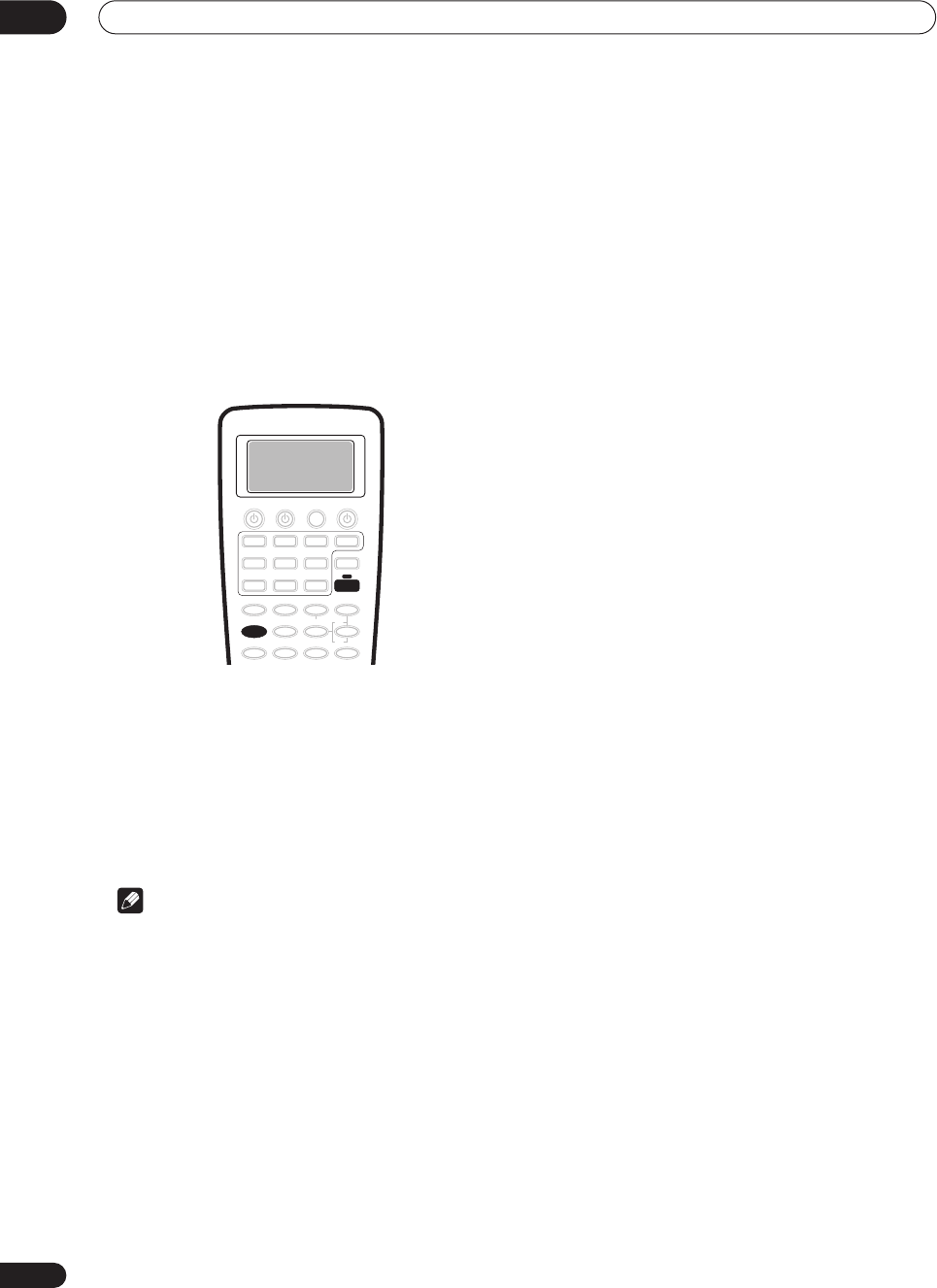
Listening to your system
05
42
En
Selecting the input signal type
Most of the audio inputs have both analog and digital
jacks. You can select the type of signal to be used in each
case.
The input signal type for the current input is indicated in
the display. With digital signals, the signal type (Dolby
Digital or DTS) also shows in the display.
The default
AUTO
setting is usually sufficient, letting the
receiver decide the most suitable signal type. However, in
other cases (for example, if you want to record the analog
output of a digital source) then you should set the input
signal type to analog.
1Press RECEIVER.
2 Press SIGNAL SEL to select the type of input
signal for the current source.
Press repeatedly to choose between:
•
AUTO
– The receiver selects the first available signal
in the following order:
DIGITAL
;
ANALOG
.
•
ANALOG
– Selects an analog signal.
•
DIGITAL
– Selects an optical or coaxial digital signal.
Note
• If no digital inputs are assigned for the current
source, the input signal type is fixed to
ANALOG
.
• When using
DIGITAL IN
terminals the following
digital signal formats are supported: Dolby Digital,
DTS and PCM (32, 44.1, 48, 88.2 and 96 kHz sampling
frequencies). If your source is not supported, select
ANALOG
.
• Some DVD players don’t output DTS signals. For
more details, refer to the instruction manual supplied
with your DVD player.
• The audio signal from karaoke microphones and
some LDs is not output from the digital outputs.
Select
ANALOG
to listen to these formats.
•If you want to play DTS-encoded sources, you need to
have digital connections. If
ANALOG
is selected,
you’ll hear digital noise through your speakers.
SIGNAL SEL
RECEIVER
VSX-9300.book 42 ページ 2004年5月21日 金曜日 午前11時28分
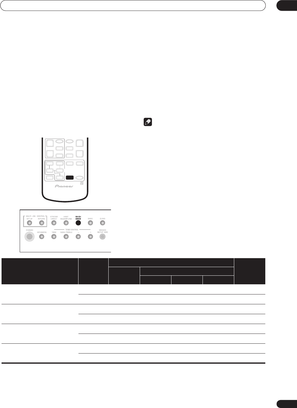
Listening to your system 05
43
En
Using the surround back channel
• Default setting:
SB CH ON
You can have the receiver automatically use 6.1 or 7.1
decoding for 6.1 encoded sources (for example, Dolby
Digital EX or DTS-ES), or you can choose to always use
6.1 or 7.1 decoding with other sources (for example, 5.1
encoded material). With 5.1 encoded sources, a
surround back channel will be generated, but the
material may sound better in the 5.1 format for which it
was originally encoded, in which case you can simply
switch the surround back channel off. The table below
indicates when you will hear the surround back channel
when playing various kinds of sources.
=Sound plays
through surround back channel speaker(s)
• Press SB CH MODE repeatedly to cycle through
the surround back channel options.
Each press changes the setting as follows (see the table
above for an explanation of each):
•
SB CH ON
– 6.1 or 7.1 encoding is always used (for
example, on 5.1 encoded material)
•
SB CH AUTO
– Automatically switches to 6.1 or 7.1
decoding for 6.1 encoded sources (for example,
Dolby Digital EX or DTS-ES)
•
SB CH OFF
– Surround back channel is switched off
Note
• You will only hear the surround back channel when
you’ve selected
Normal Surround
in the
Surround
back speaker setting
on page 51. Changing the
speaker system may automatically change this
setting (see notes below).
• If the surround back speaker is set to
NO
in
Speaker
Setting
on page 51, or you have selected a Second
Zone speaker B setup, you can only use the virtual
surround back effect (see next page).
•You can’t use the surround back channel setting with
MULTI CH IN
or
STEREO
/
DIRECT
.
•You can’t use the surround back channel feature with
sources over 48kHz when using one of the digital
inputs.
SB CH
MODE
Type of source SB CH
mode
Surround modes (Basic)
Advanced
effects
Multichannel
sources
Stereo sources
2
Pro Logic
II x
2
Pro Logic
NEO:6
Dolby Digital EX/DTS-ES encoded
multichannel source with 6.1ch
surround
ON
AUTO
Dolby Digital/DTS encoded
multichannel source
ON
AUTO
Dolby Digital/DTS encoded stereo
source; other digital stereo source
ON
AUTO
Analog 2-channel (stereo) source
ON
AUTO
VSX-9300.book 43 ページ 2004年5月21日 金曜日 午前11時28分
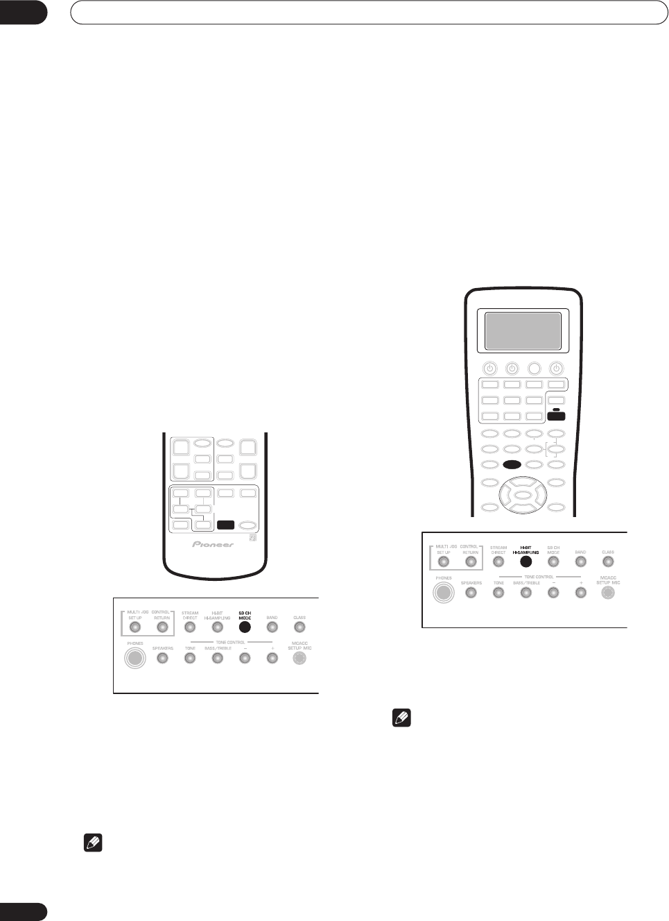
Listening to your system
05
44
En
Listening with virtual surround back
speakers
• Default setting:
VIRTL SB OFF
If you don’t have real surround back speakers connected,
you can use the Virtual Surround Back feature to
simulate one.
Sometimes the material may sound better in the 5.1
format for which it was originally encoded. In this case
you can have the receiver only apply this effect to 6.1
encoded sources like Dolby Digital EX or DTS-ES (
VIRTL
SB AUTO
), or you can simply switch it off (
VIRTL SB OFF
).
For stereo sources, you’ll have to select one of the
NEO:6
modes or an advanced effect mode (see
Listening in
surround sound
on page 37) to use the Virtual Surround
Back feature.
Note that this feature only works when the surround
channels are active and the surround back speaker is set
to
NO
in
Speaker Setting
on page 51.
See also
Using the surround back channel
above.
• Press SB CH MODE repeatedly to cycle through
the virtual surround back channel options.
Each press cycles through the options as follows:
•
VIRTL SB ON
– Virtual Surround Back is used for all
sources
•
VIRTL SB AUTO
– Automatically applied to 6.1
encoded sources (for example, Dolby Digital EX or
DTS-ES)
•
VIRTL SB OFF
– Virtual Surround back is switched off
Note
•You can’t use the Virtual Surround Back setting with
THX CINEMA
,
PRO LOGIC II, PRO LOGIC IIx
,
MULTI
CH IN
or
STEREO
/
DIRECT
.
•You can’t use the Virtual Surround Back feature with
sources over 48kHz when using one of the digital
inputs.
• When using the Virtual Surround Back feature with
the surround modes,
+VSB
shows in the display.
Using the audio scaler for Hi-bit and
Hi-sampling
• Default setting:
Off
You can use the audio scaler to create a wider dynamic
range with digital sources like CDs or DVDs.
1 If you’re using the remote, press RECEIVER.
2 Press HI-BIT (HI-BIT/HI-SAMPLING on the front
panel).
Note
• You can’t use the audio scaler with
MULTI CH IN
.
• You can’t use the audio scaler with sources over
48kHz when using one of the digital inputs.
• If you switch on the audio scaler when
DIRECT
is
selected, the receiver automatically switches to
STEREO
.
SB CH
MODE
HI-BIT
RECEIVER
VSX-9300.book 44 ページ 2004年5月21日 金曜日 午前11時28分
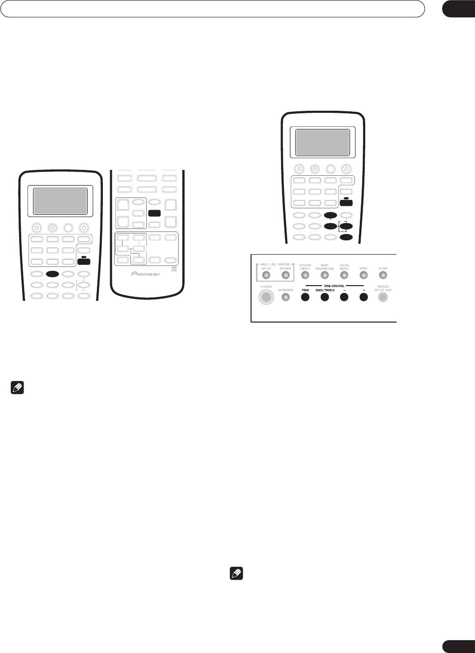
Listening to your system 05
45
En
Using Midnight and Loudness
listening
• Default setting:
Off
The Midnight listening feature makes quieter sounds
more audible, allowing you to hear effective surround
sound at low volume levels.
The Loudness feature boosts the bass and treble in audio
sources, useful for listening at low volumes.
1Press RECEIVER.
This step is only necessary if you want to use Loudness.
2 Press MIDNIGHT or LOUDNESS to switch the
effect on or off.
The mode you’ve selected lights in the display.
Note
• You can’t use the Midnight and Loudness modes at
the same time.
• You can’t use these modes with
THX CINEMA
or
MULTI CH IN
.
• These modes automatically adjust according to the
volume at which you’re listening. However, the
volume must be under -20dB for these features to
take effect.
• You can’t use these modes with sources over 96kHz
when using one of the digital inputs.
•If you switch on either of these modes when
DIRECT
is selected, the receiver automatically switches to
STEREO
.
Using the tone control
You can use the tone control to make customized
settings for the bass and treble.
Switching the tone control on or off
• Default setting:
Off
You’ll need to switch the tone control on to adjust the
bass and treble below.
1 If you’re using the remote, press RECEIVER.
2 Press TONE to switch the tone control on or off.
TONE
shows in the display when the tone control is
switched on.
Adjusting the bass and treble
• Default setting: Bass:
0
,
Treble:
0
You can adjust the bass and treble controls separately to
adjust the overall tone.
1 Press BASS/TREBLE repeatedly to select BASS or
TREBLE.
If you see
TONE:BYPASS
in the display, the tone control
needs to be switched on (see above).
2 Use the +/– buttons to adjust the sound.
The bass and treble can be adjusted from
–6
to
+6
.
Note
•You can’t use the tone control with
THX CINEMA
or
MULTI CH IN
.
• You can’t use the tone control with sources over
96kHz when using one of the digital inputs.
LOUDNESS
RECEIVER
MIDNIGHT
TONE
BASS/TREBLE
RECEIVER
+
VSX-9300.book 45 ページ 2004年5月21日 金曜日 午前11時28分
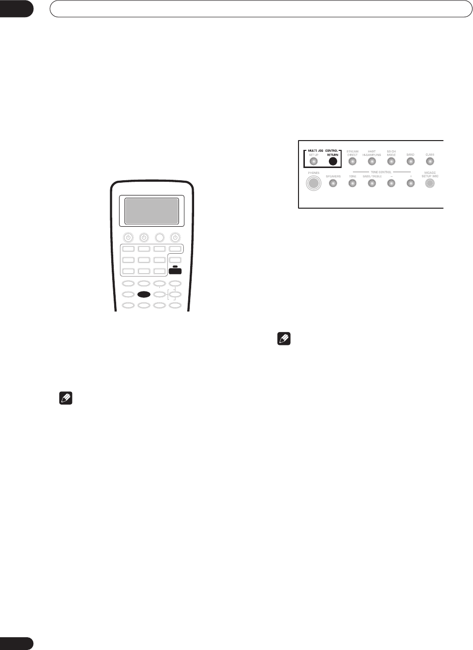
Listening to your system
05
46
En
• If you switch on the tone control when
DIRECT
is
selected, the receiver automatically switches to
STEREO
.
Reducing noise during playback
• Default setting:
Off
If you have a noisy source (for example, cassette or video
tape with lots of background noise), you may be able to
improve the quality of the sound by switching on digital
noise reduction (
DNR
).
1Press RECEIVER.
2 Press the DNR button to switch digital noise
reduction on or off.
DNR
shows in the display when digital noise reduction is
switched on.
Note
• Depending on the source, there may not be a
noticeable improvement in the quality of the sound.
• You can’t use digital noise reduction with
THX
CINEMA
or
MULTI CH IN
.
• You can’t use digital noise reduction with sources
over 48kHz when using one of the digital inputs.
•If you switch on digital noise reduction when
DIRECT
is selected, the receiver automatically switches to
STEREO
.
Listening to dual mono soundtracks
• Default setting:
DUAL ch1
You can specify how dual mono encoded Dolby Digital
soundtracks should be played. Dual mono is not widely
used, but is sometimes necessary when two languages
need to be sent to separate channels.
1Press and hold the RETURN button for more than
three seconds to select a DUAL MONO setting.
You will see the following settings cycle in the display:
•
DUAL ch1
– Only channel 1 is played
•
DUAL ch2
– Only channel 2 is played
•
DUAL ch1/ch2
– Both channels are played through
the front speakers
2Release the button when you see the setting you
want.
Note
• This setting works only with dual mono encoded
Dolby Digital soundtracks.
SETUP
DNR
RECEIVER
VSX-9300.book 46 ページ 2004年5月21日 金曜日 午前11時28分
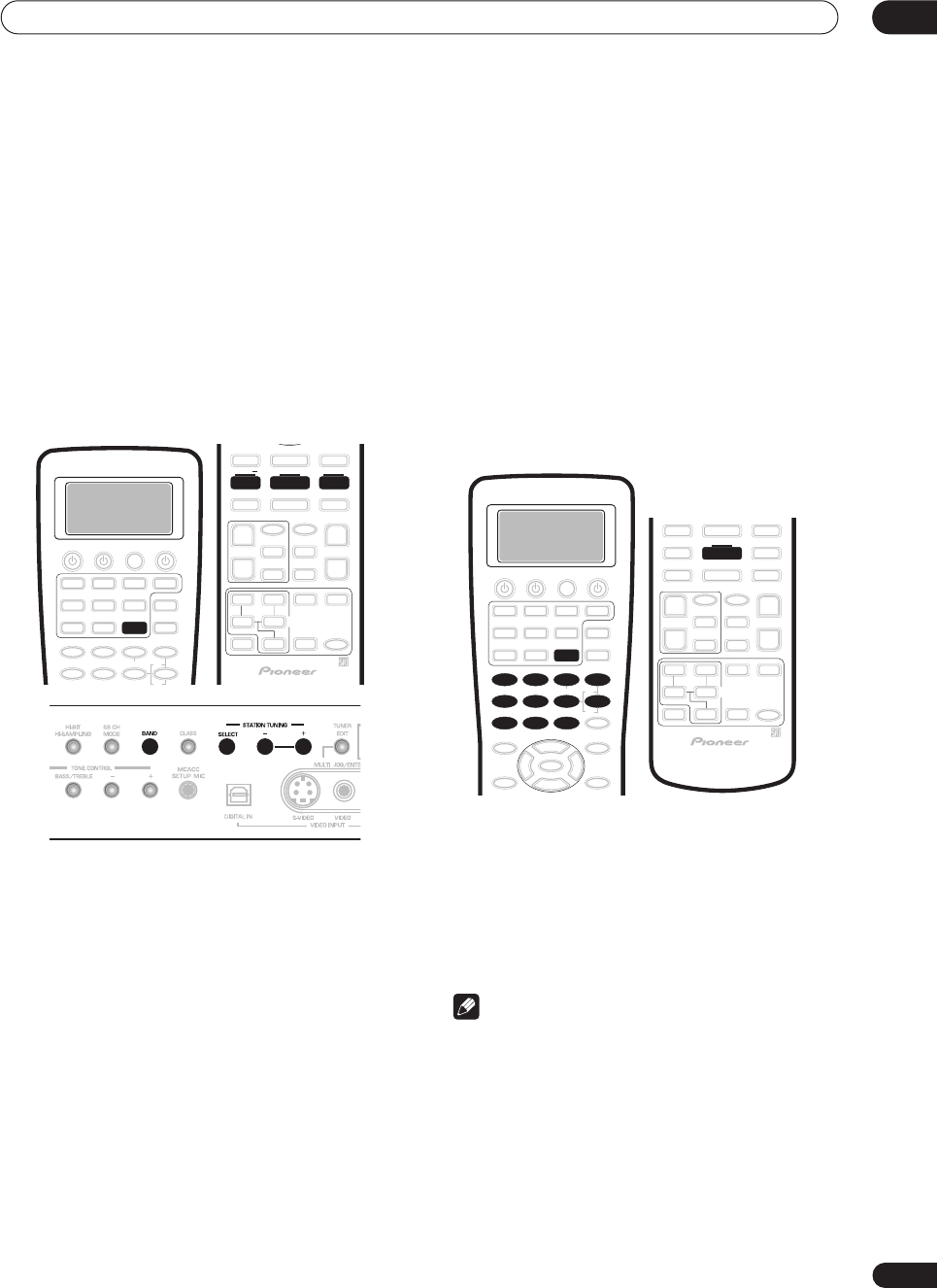
Using the tuner 06
47
En
Chapter 6
Using the tuner
Finding a station
The following steps show you how to tune in to FM and
AM radio broadcasts using the automatic (search) and
manual (step) tuning functions. If you already know the
exact frequency of the station you want to listen to, see
Tuning directly to a station
below. Once you are tuned to
a station you can memorize the frequency for recall
later—see
Memorizing station presets
below for more on
how to do this.
1 Press TUNER, then press BAND to change the
band (FM or AM), if necessary.
Each press switches the band between FM and AM.
• You can also use the front panel
MULTI JOG
dial to
select the tuner.
2 Tune to a station using the TUNING +/– buttons.
On the front panel, press
SELECT
first to switch to the
frequency select mode for (
STATION
)
TUNING +/–.
Automatic tuning
To search for stations in the currently selected band,
press and hold either of the
TUNING +/–
buttons for
about a second. The receiver will start searching for
the next station, stopping when it has found one.
Repeat this step to search for other stations.
Manual tuning
To change the frequency one step at a time, press the
TUNING +/–
buttons repeatedly.
High speed tuning
Press and hold the
TUNING +/–
buttons for high
speed tuning, releasing the button once you reach
the frequency you want.
Tuning directly to a station
Sometimes, you'll already know the frequency of the
station you want to listen to. In this case, you can simply
enter the frequency directly using the number buttons on
the remote control.
1 Press TUNER, then press BAND to change the
band (FM or AM), if necessary.
Each press switches the band between FM and AM.
2Press DIRECT ACCESS.
3 Use the number buttons to enter the frequency
of the radio station.
For example, to tune to 106.00 (FM), press
1
,
0
,
6
,
0
,
0
.
Note
•If you make a mistake while inputting the frequency,
press the
DIRECT ACCESS
button again to cancel the
frequency and start again.
SETUP
TUNER
TUNING BAND TUNING
+
1
5
90
678
342
DIRECT ACCESS
TUNER
BAND
VSX-9300.book 47 ページ 2004年5月21日 金曜日 午前11時28分
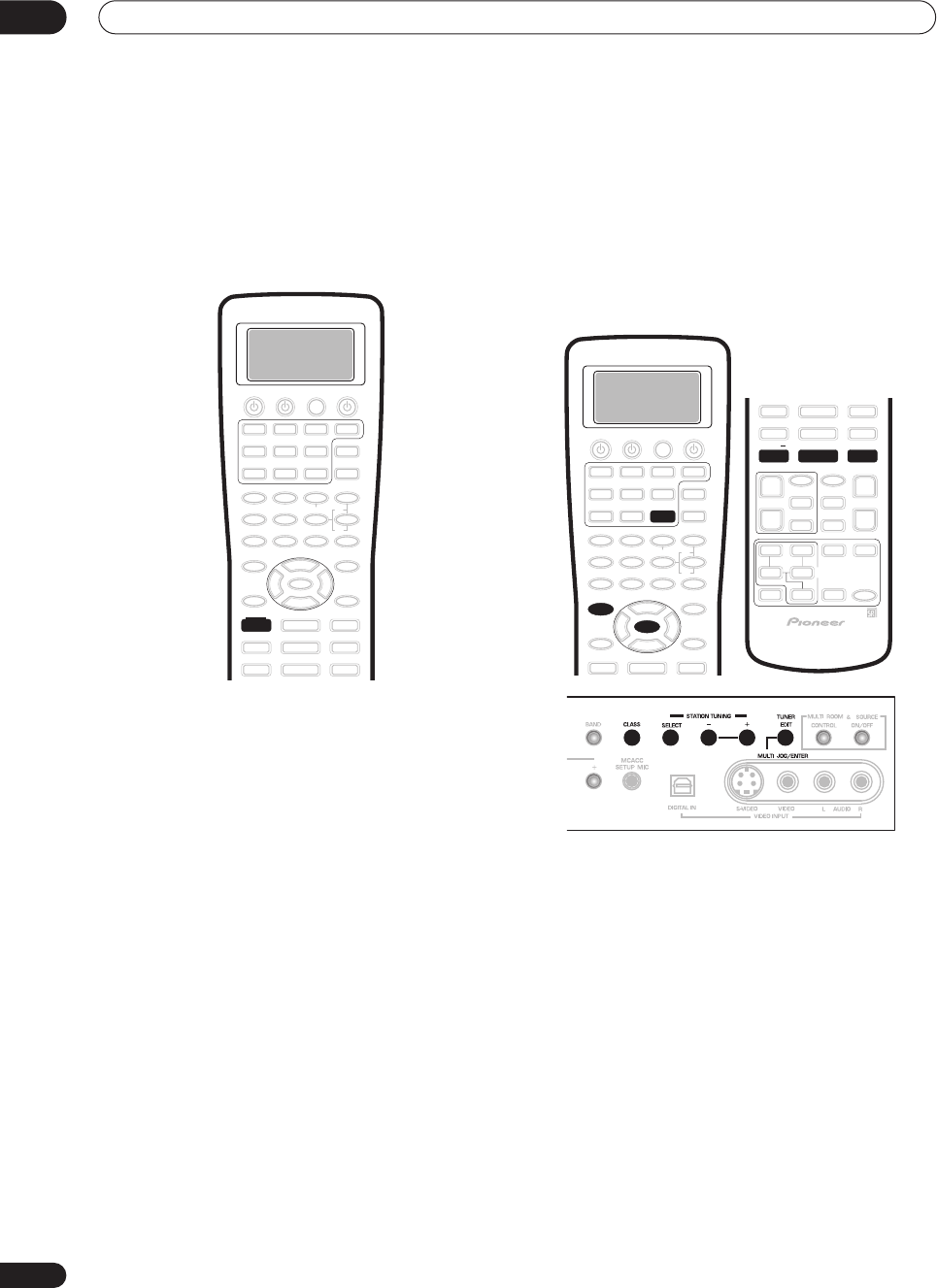
Using the tuner
06
48
En
MPX mode
If there is interference or noise during a stereo FM radio
broadcast (the
STEREO
indicator is lit), or the radio
reception is weak, press
MPX
on the remote to switch the
receiver into mono reception mode (the
MONO
indicator
lights). This should improve the sound quality and allow
you to enjoy the broadcast.
Memorizing station presets
If you often listen to a particular radio station, it's
convenient to have the receiver store the frequency for
easy recall whenever you want to listen to that station.
This saves the effort of manually tuning in each time. The
receiver can memorize up to 30 stations, stored in three
banks, or classes, (A, B and C) of 10 stations each. When
memorizing FM frequencies, the receiver also stores the
MPX setting (see
MPX mode
above).
1 Tune to a station you want to memorize.
See
Finding a station
above and
Tuning directly to a
station
above for more details on how to do this.
2Press TUNER EDIT.
The display shows
MEMORY INPUT
then a blinking
memory class (
A
,
B
or
C
).
3 Press CLASS to select one of the three classes.
Press repeatedly to cycle through the three memory
classes,
A
,
B
and
C
.
4Use the STATION +/– buttons to select the station
preset you want.
On the front panel, press
SELECT
first to switch to the
station select mode for
STATION
(
TUNING
)
+/–
.
•You can also use the front panel
MULTI JOG
dial or
the number buttons on the remote control to select
the station preset.
5 While the display is blinking, press ENTER.
6Repeat steps 1 – 5 to memorize up to 30 stations.
MPX
ENTER
TUNER
TUNER EDIT
STATION DTV MENU CLASS STATION
+
VSX-9300.book 48 ページ 2004年5月21日 金曜日 午前11時28分
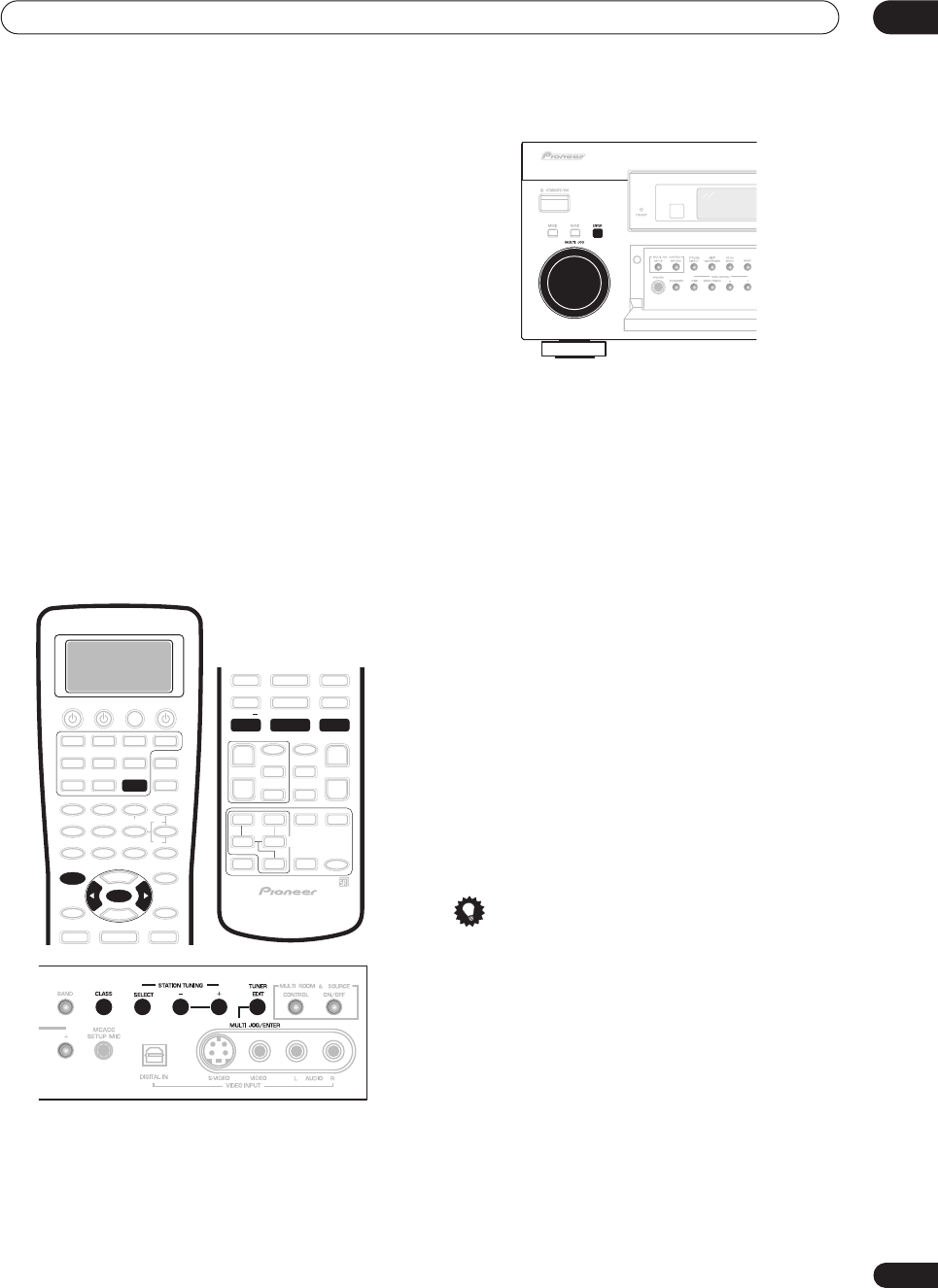
Using the tuner 06
49
En
Listening to memorized station presets
You can do this from both the remote control and the
front panel.
1 Press CLASS to select the class in which the
station is stored.
Press repeatedly to cycle through the three memory
classes,
A
,
B
and
C
.
2Use the STATION +/– buttons to select the station
memory in which the station is stored.
On the front panel, press
SELECT
first to switch to the
station select mode for
STATION
(
TUNING
)
+/–
.
• You can also use the number buttons or the
/
(cursor left/right) buttons on the remote control to
recall the station preset.
Naming station presets
You can input a name of up to four characters for each
preset station in the receiver’s memory. For example, you
could input
Jazz
for that station and when you listen to it
the name, rather than the frequency, will appear in the
front panel display.
1 Press CLASS repeatedly to select the class.
Press repeatedly to cycle through the three memory
classes,
A
,
B
and
C
.
2 Use the STATION +/– buttons to select an FM or
AM preset station.
On the front panel, press
SELECT
first to switch to the
station select mode for
STATION
(
TUNING
)
+/–
.
3 Press TUNER EDIT to select the station name
mode.
4 Edit the name as necessary and press ENTER.
Use the
/
(cursor left/right) buttons or the front panel
MULTI JOG
dial to change the character and
ENTER
to
confirm (or to add a space if no character is input). The
name can be up to four characters (the possible
characters are listed below).
ABCDEFGHIJKLMNOPQRSTUVWXYZ
abcdefghijklmnopqrstuvwxyz
0123456789
!”#$%&’()*+,–./:;<=>?@[ \ ]^_{|} (space)
To exit the process at any time, press
TUNER EDIT
.
5 Repeat steps 2 – 4 to memorize up to 30 preset
broadcast station names.
Tip
• To change a station name, just enter the new name
over the top of the old one. To erase a station name,
enter a new name of four spaces.
• You can switch between the frequency display and
the station name display using the remote control
DISP MODE
button.
ENTER
TUNER
TUNER EDIT
STATION DTV MENU CLASS STATION
+
VSX-9300.book 49 ページ 2004年5月21日 金曜日 午前11時28分
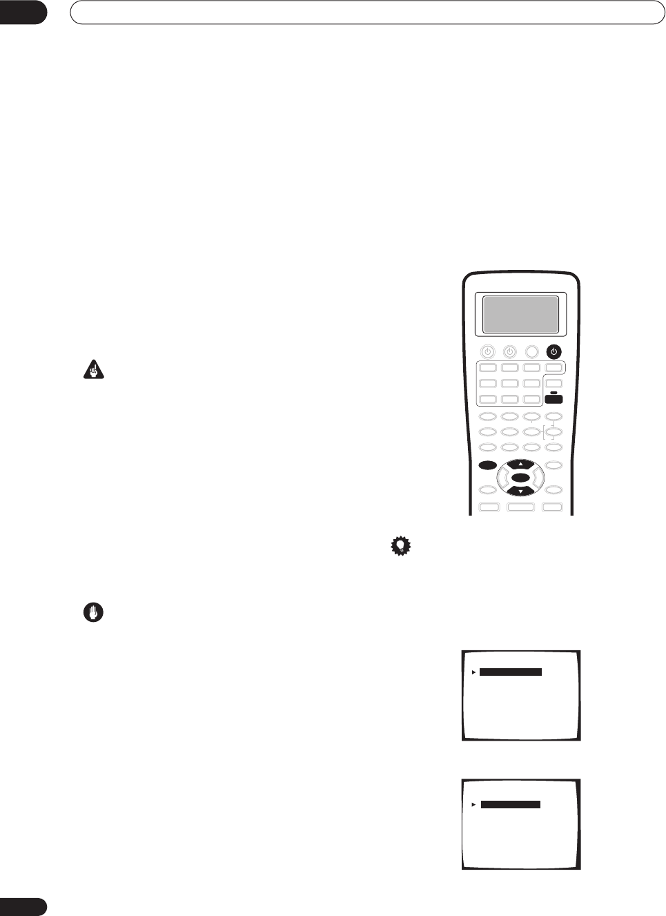
The Surround Setup menu
07
50
En
Chapter 7
The Surround Setup menu
Making
receiver
settings from the
Surround Setup menu
This receiver allows you to make detailed settings to
optimize the surround sound performance. You only
need to make these settings once (unless you change the
placement of your current speaker system or add new
speakers.).
These settings are designed to fine-tune your system, but
if you’re satisfied with the settings made in
Automatically
setting up for surround sound
on page 12, it isn’t
necessary to make all of these settings.
Important
•For some of the settings below, you’ll have to connect
the setup microphone to the front panel and place it
about ear level at your normal listening position. See
Automatically setting up for surround sound
on
page 12 if you’re unsure how to do this. Also see
Other problems when using the Auto Surround Setup
on page 14 for notes regarding high background
noise levels and other possible interference.
•If you’re using a subwoofer, switch it on and turn up
the volume to the middle position.
• After three minutes of inactivity during the
Auto
setup options, the OSD will go to sleep until a button
is pressed. With other screens, the receiver
automatically exits and no settings will be made.
Caution
•The test tones used in the Surround Setup are output
at high volume (the volume increases to 0dB
automatically).
1 Switch on the receiver and your TV.
Use the
RECEIVER
button to switch on.
•If headphones are connected to the receiver,
disconnect them.
2 Using the remote control, press RECEIVER, then
press the SYSTEM SETUP button.
An on-screen display (OSD) appears on your TV. Use the
/
(cursor up/down) buttons and
ENTER
on the remote
control to navigate through the screens and select menu
items.
Tip
• You can also use the front panel display to make
settings. You can also use the
MULTI JOG
dial and
ENTER
on the front panel instead of the
/
(cursor
up/down) buttons and
ENTER
on the remote control.
3 Select ‘Surround Setup’ then press ENTER.
4 Select the setting you want to adjust.
SYSTEM SETUP
ENTER
RECEIVER
RECEIVER
System Setup
[ 1. Surround Setup ]
[ 2. THX CINEMA Setup ]
[ 3. Input Assign ]
[ 4. Function Rename ]
[ 5. PHONO/LINE Setup ]
[ 6. Multi Room ]
[ 7. 12V Trigger ]
[ Exit ]
1.Surround Setup
[ SurrBack System ]
[ Auto Setting ]
[ Normal ]
[ Expert ]
[ Exit ]
VSX-9300.book 50 ページ 2004年5月21日 金曜日 午前11時28分
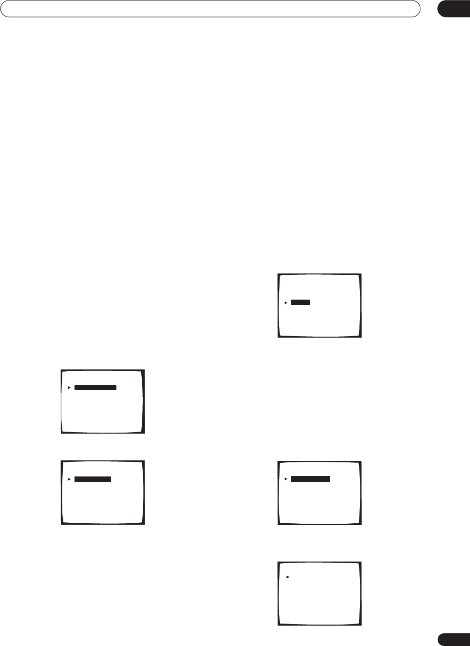
The Surround Setup menu 07
51
En
•
SurrBack System
– Specify how you are using your
surround back speakers (see
Surround back speaker
setting
below).
•
Auto Setting
– This is a quick and easy automatic
surround setup (see
Automatically setting up for
surround sound
on page 12).
•
Normal
– Specify the size, number, distance and
overall balance of the speakers you’ve connected
(see
Normal surround setting
below).
•
Expert
– Use this menu to fine tune your surround
setup (see
The Expert setup menu
on page 79).
5 Make the adjustments necessary for each
setting, pressing ENTER to confirm after each
setting.
Surround back speaker setting
• Default setting:
Normal
There are several ways you can use the surround back
speaker channels with this system. In addition to a
normal home theater setup where they are used for the
surround back speakers, they can be used for bi-amping
the front speakers or as an independent speaker system
in another room.
1 Select ‘SurrBack System’ from the Surround
Setup menu.
See
Making receiver settings from the Surround Setup
menu
above if you’re not already at this screen.
2 Select the surround back speaker setting.
•
Normal System
– Select for normal home theater
use with surround back speakers in your main
(speaker system A) setup.
•
Second Zone
– Select to use the (surround back) B
speaker terminals to listen to stereo playback in
another room (see
Second Zone speaker B setup
on
page 67).
•
Front Bi-Amp
– Select this setting if you’re bi-
amping your front speakers (see
Bi-amping your front
speakers
on page 68).
•
MR&S
– Select to use the (surround back) B speaker
terminals for an independent system in another room
(see
Multi-room listening
on page 69).
3 When you’re finished, select ‘Exit’.
You will return to the Surround Setup menu.
Normal surround setting
If you aren’t satisfied with the results the Auto Setup
(
Automatically setting up for surround sound
on page 12),
you can use these settings to adjust speaker parameters
manually. Note that these settings overwrite the settings
made with the Auto Setup.
• Select ‘Normal’ from the Surround Setup menu.
See
Making receiver settings from the Surround Setup
menu
above if you’re not already at this screen.
Speaker Setting
• Default setting:
SMALL
(all speakers) /
Subwoofer
–
YES
Use this setting to specify your speaker configuration
(size, number of speakers). You can make sure that the
settings made in
Automatically setting up for surround
sound
on page 12 are correct.
1Choose ‘Speaker Setting’ from the Normal setup
menu.
2Choose the set of speakers that you want to set
then select a speaker size.
1.Surround Setup
[ SurrBack System ]
[ Auto Setting ]
[ Normal ]
[ Expert ]
[ Exit ]
SurrBack System
[ Normal System
[ Second Zone
[ Front Bi-Amp
[ MR&S
[ Exit
]
]
]
]
]
1.Surround Setup
[ SurrBack System ]
[ Auto Setting ]
[ Normal ]
[ Expert ]
[ Exit ]
Normal
[ Speaker Setting
]
[ Channel Level
]
[ Speaker Distance
]
[ Exit ]
Speaker Setting
Front [ SMALL ]
Center [ SMALL ]
Surround [ SMALL ]
SurrBack [ SMALLX2 ]
Subwoofer [ YES ]
[Exit]
(THX Speaker:SMALL)
VSX-9300.book 51 ページ 2004年5月21日 金曜日 午前11時28分

The Surround Setup menu
07
52
En
Use
/
(cursor up/down) to select the size (and
number) of each of the following speakers:
•
Front
– Select
LARGE
if your front speakers
reproduce bass frequencies effectively, or if you
didn’t connect a subwoofer. Select
SMALL
to send
the bass frequencies to the subwoofer.
•
Center
– Select
LARGE
if your center speaker
reproduces bass frequencies effectively, or select
SMALL
to send bass frequencies to the other
speakers or subwoofer. If you didn’t connect a center
speaker, choose
NO
(the center channel is sent to
the front speakers).
•
Surround
– Select
LARGE
if your surround speakers
reproduce bass frequencies effectively. Select
SMALL
to send bass frequencies to the other
speakers or subwoofer. If you didn’t connect
surround speakers choose
NO
(the sound of the
surround channels is sent to the front speakers or a
subwoofer).
•
SurrBack
– Select the number of surround back
speakers you have (one, two or none). Select
LARGE
if your surround back speakers reproduce bass
frequencies effectively. Select
SMALL
to send bass
frequencies to the other speakers or subwoofer. If
you didn’t connect surround back speakers choose
NO
.
•
Subwoofer
– LFE signals and bass frequencies of
channels set to
SMALL
are output from the
subwoofer when
YES
is selected (see notes below).
Choose the
PLUS
setting if you want the subwoofer to
output bass sound continuously or you want deeper
bass (the bass frequencies that would normally come
out the front and center speakers are also routed to
the subwoofer). If you did not connect a subwoofer
choose
NO
(the bass frequencies are output from
other speakers).
Note
• If you selected
Second Zone
,
Front Bi-Amp
, or
MR&S
in
Surround back speaker setting
above you
can’t adjust the surround back settings.
• If you select
SMALL
for the front speakers the
subwoofer will automatically be fixed to
YES
. Also,
the center and surround speakers can’t be set to
LARGE
if the front speakers are set to
SMALL
. In this
case, all bass frequencies are sent to the subwoofer.
•If the surround speakers are set to
NO
, the surround
back speakers will automatically be set to
NO
.
• If you select one surround back speaker only, make
sure that speaker is hooked up to the left surround
back terminal.
•If you’re using a THX speaker setup, we recommend
setting all speakers to
SMALL
.
3 When you're finished, select ‘Exit’.
You will return to the Normal setup menu.
Tip
• If you have a subwoofer and like lots of bass, it may
seem logical to select
LARGE
for your front speakers
and
PLUS
for the subwoofer. This may not, however,
yield the best bass results. Depending on the speaker
placement of your room you may actually experience
a decrease in the amount of bass due to low
frequency cancellations. In this case, try changing
the position or direction of speakers. If you can’t get
good results, listen to the bass response with it set to
PLUS
and
YES
or the front speakers set to
LARGE
and
SMALL
alternatively and let your ears judge which
sounds best. If you’re having problems, the easiest
option is to route all the bass sounds to the
subwoofer by selecting
SMALL
for the front speakers.
Channel Level
• Default setting:
0dB
(all speakers)
Using the channel level setting, you can adjust the overall
balance of your speaker system, an important factor
when setting up a home theater system.
1 Select ‘Channel Level’ from the Normal setup
menu.
2 Select a setup option and press ENTER to start
the test tones.
•
Manual
– Move the test tone manually from speaker
to speaker and adjust individual channel levels.
•
Auto
– Adjust channel levels as the test tone moves
from speaker to speaker automatically.
Normal
[ Speaker Setting ]
[ Channel Level
]
[ Speaker Distance
]
[ Exit ]
Channel Level
Test Tone
Setting Start
Caution!!
Test tone is
output loudly.
[ Manual ]
[ Auto ]
[
Exit
]
VSX-9300.book 52 ページ 2004年5月21日 金曜日 午前11時28分
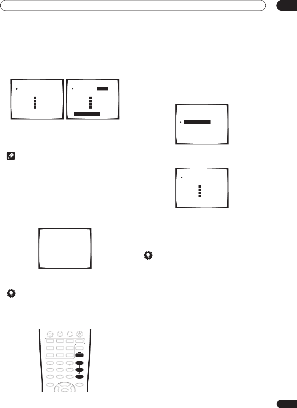
The Surround Setup menu 07
53
En
3 Adjust the level of each channel using the
/
(cursor up/down) buttons.
If you selected
Manual
, use
/
(cursor up/down) and
ENTER
to select speakers. The
Auto
setup will output
test tones in the order shown on-screen:
Adjust the level (+/– 10dB) of each speaker as the test
tone is emitted.
Note
•If you are using a Sound Pressure Level (SPL) meter,
take the readings from your main listening position
and adjust the level of each speaker to 75 dB SPL (C-
weighting/slow reading).
•The subwoofer test tone is output at low volumes. You
may need to adjust the level after testing with an
actual soundtrack.
4 If you selected ‘Manual’, select ‘Exit’ to finish.
With ‘Auto’, simply press ENTER.
You will return to the Normal setup menu.
Tip
• You can change the channel levels at any time by
pressing
RECEIVER
then
EFFECT/CH SEL
(to select
the channel you want to adjust) on the remote. Use
the
+
/
–
buttons to increase/decrease the level.
Speaker Distance
• Default setting:
10.0 ft
(all speakers)
For good sound depth and separation from your system,
you need to specify the distance of your speakers from
the listening position. The receiver can then add the
proper delay needed for effective surround sound.
1Select ‘Speaker Distance’ from the Normal setup
menu.
2 Specify the distance of each speaker from the
listening position.
Adjust the distance of each speaker within the range of
0.5–45 feet.
3 When you're finished, select ‘Exit’.
You will return to the Normal setup menu.
Tip
• For best surround sound, make sure the surround
back speakers are the same distance.
0.0
dB
0.0
dB
0.0
dB
0.0
dB
0.0
dB
0.0
dB
0.0
dB
0.0
dB
Channel Level
Left [ ]
Center [ ]
Right [ ]
Surround [ ]
SurrBack [ ]
SurrBack [ ]
Surround [ ]
Subwoofer [ ]
[
Exit
]
R
R
L
L
Manual setup
0.0
dB
0.0
dB
0.0
dB
0.0
dB
0.0
dB
0.0
dB
0.0
dB
0.0
dB
Channel Level
Left [ ]
Center [ ]
Right [ ]
Surround [ ]
SurrBack [ ]
SurrBack [ ]
Surround [ ]
Subwoofer [ ]
Exit=Push Enter
R
R
L
L
Auto setup
Channel Level
Test Tone
Please Wait
+
EFFECT/CH SEL
RECEIVER
Normal
[ Speaker Setting ]
[ Channel Level
]
[ Speaker Distance
]
[ Exit ]
10.0ft
10.0ft
10.0ft
10.0ft
10.0ft
10.0ft
10.0ft
10.0ft
Speaker Distance
Left [ ]
Center [ ]
Right [ ]
Surround [ ]
SurrBack [ ]
SurrBack [ ]
Surround [ ]
Subwoofer [ ]
[Exit ]
R
R
L
L
VSX-9300.book 53 ページ 2004年5月21日 金曜日 午前11時28分
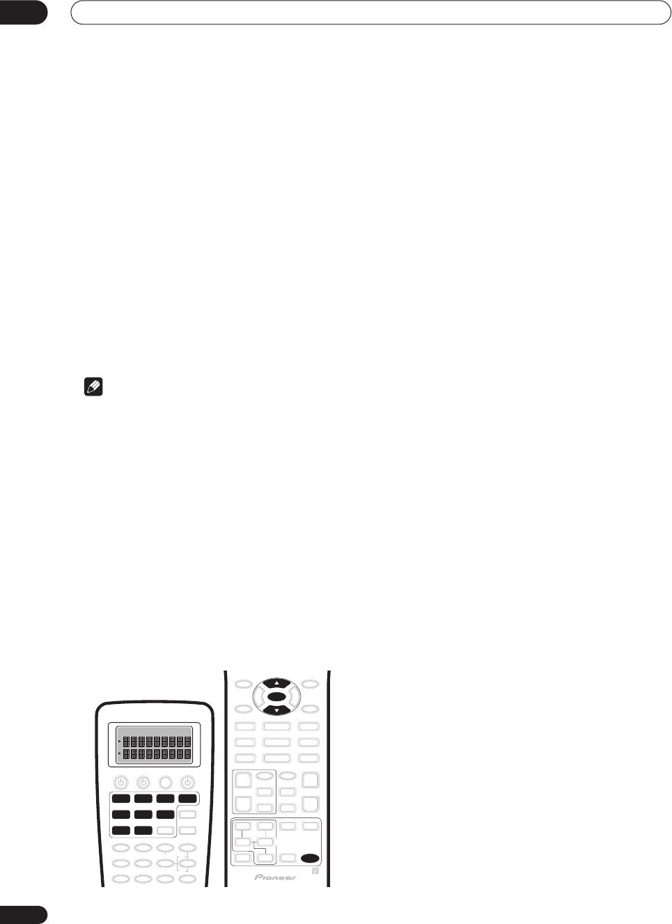
Controlling other equipment
08
54
En
Chapter 8
Controlling other equipment
Using the remote control with other
components
The supplied remote control can operate not only this
receiver, but also your TV, DVD player and other
components. If the component is listed in the remote
control's memory, you can simply follow the steps in
Recalling preset codes
below. If the component is not
listed, or if you want the remote to learn additional
operations, see
Programming signals from other remote
controls
on page 55.
See
Preset code brands
on page 97 for a list of brands
available for each component.
Note
• You can cancel or exit any of the following steps by
pressing
REMOTE SETUP
.
• After one minute of inactivity, the remote goes to
sleep. Press any button to reactivate the remote
display and continue.
• TV codes (for example, codes for TV, CATV, Satellite
TV or DTV) can only be assigned to the
TV/SAT
or
TV
CONT
button.
• The default preset setting for all functions is a corre-
sponding Pioneer component. Note that where two
buttons are listed, the first component is the the
default (for example,
MD/TAPE2
is an MD), and the
VIDEO
button is set to a Pioneer DVD player.
Recalling preset codes
The following steps show you how to recall preset codes
for each input source. Use the remote control to do this.
1Make sure the component you want to control is
switched on.
2Press and hold REMOTE SETUP for three seconds.
The
REMOTE SETUP
menu appears in the remote control
display.
3 Use
/
(cursor up/down) to select ‘Preset’ from
the menu and press ENTER.
Select Function
flashes in the display.
4 Press the MULTI CONTROL button that matches
the connection for the component you want to
control.
For example, press
DVD/LD
if you want to control the
DVD player that you connected to the
DVD/LD
terminals.
• Choosing a button that’s already assigned will over-
write the old preset (and any other operations you
may have programmed).
• You can’t assign the
RECEIVER
or
TUNER
buttons.
5 Use
/
(cursor up/down) to choose the type of
component you’ve connected and press ENTER.
Following our example above, you would select
DVD
, but
you should choose from the
ITEM
list according to the
component connected. For example, if you connected a
DVD recorder instead of a VCR to the
VCR2
inputs, you
would select
DVR
here.
6 Use
/
(cursor up/down) to select the manufac-
turer’s name from the list.
If there is more than one component type for the
manufacturer, then
–1
,
–2
, etc. will appear in the display.
Start with the first one in the list.
7Point the remote at the component you want to
control and press ENTER.
OK?
shows in the remote control display.
If the component switches off
(into standby), use
/
(cursor up/down) and
ENTER
to select
Yes
.
COMPLETE
shows in the display to confirm that the component
preset has been recalled properly.
If the component doesn’t switch off
(into standby), use
/
(cursor up/down) and
ENTER
to select
No
. Choose
another preset for your manufacturer (step 6).
• If the component you are trying to control doesn’t
have a standby mode, simply select
Yes
above then
confirm that it is the right code by testing it with
another operation button.
• If you can’t find or properly enter a preset code, you
can still teach the remote individual commands from
another remote control (see
Programming signals
from other remote controls
below).
DVD/LD
VCR2 VIDEO CD
TV/SAT
TV CONT
MULTI CONTROL
VCR1 /
DVR
CD-R/
TAPE1
MD/
TAPE2
REMOTE
SETUP
ENTER
VSX-9300.book 54 ページ 2004年5月21日 金曜日 午前11時28分
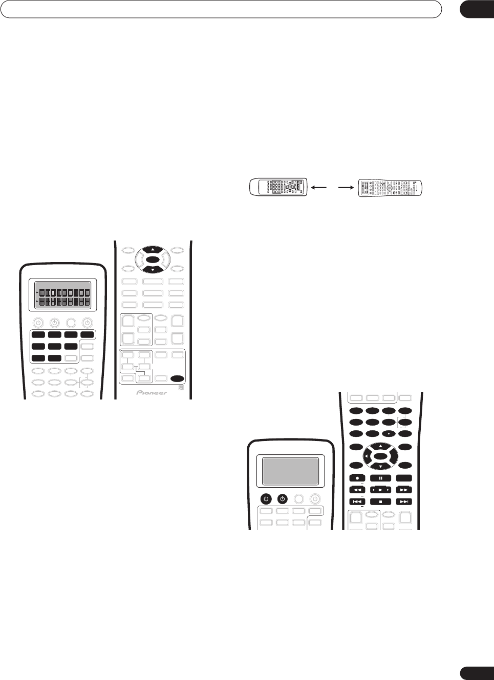
Controlling other equipment 08
55
En
8Repeat steps 3 – 7 for any other components you
want to control.
9When you’re finished, use
/
(cursor up/down)
to select ‘*Exit*’ from the menu and press ENTER.
Programming signals from other
remote controls
If the preset code for your component is not available, or
the available preset codes do not operate correctly, you
can program signals from the remote control of another
component. This can also be used to program additional
operations (buttons not covered in the presets) after
assigning a preset code in
Recalling preset codes
on
page 54.
1Press and hold REMOTE SETUP for three seconds.
The
REMOTE SETUP
menu appears on the remote
control display.
2 Use
/
(cursor up/down) to select ‘Learning’
from the menu and press ENTER.
Select Function
flashes in the display.
3 Press the MULTI CONTROL button that matches
the connection for the component you want to
control.
For example, press
DVD/LD
if you want to program an
operation for the DVD player that you connected to the
DVD/LD
terminals.
Select Key
flashes in the display.
• You can’t assign the
RECEIVER
or
TUNER
buttons.
4Select the button corresponding to the command
you want to teach the remote control.
For example, press
if you want to program the play
command from your DVD player remote control.
LEARN
flashes in the display.
• When programming
TV CONT
, you can only select
TV
, or one of the
TV CONTROL
buttons.
5 Point the two remote controls towards each
other then press the corresponding button on the
other remote control that is sending (teaching) the
signal to this receiver’s remote control.
For example, if you want to learn the playback control
signal, press
.
•The remote controls should be 2–8 inches apart, and
the
LEARN
icon should be flashing to indicate the
remote is ready to accept a signal.
If the operation has been learned
, the display will show
OK
If the operation hasn’t been learned
the display will show
NG
.
Continue?
shows in the display (if
Select Key
is flashing,
go back to step 4). Go to step 6.
• If the remote display shows
FULL
, it means the
memory is full. See
Clearing remote control settings
on page 65 to erase a programmed button you’re not
using to free up more memory.
• If
NG
keeps showing in the display, or the remote
control keeps on returning to step 4 (
Select Key
flashes in the display), it may be possible that the
command cannot be learned by this remote control.
Certain buttons represent operations that cannot be
learned from other remote controls. The buttons avail-
able are shown below:
6 Use
/
(cursor up/down) to select ‘Yes’ to
program additional signals for the current compo-
nent.
Repeat steps 4 and 5.
• To program signals for another component, select
No
and repeat steps 2 through 5.
7When you’re finished, use
/
(cursor up/down)
to select ‘*Exit*’ from the menu and press ENTER.
You will return to the
REMOTE SETUP
menu. Select
*Exit*
again to exit.
DVD/LD
VCR2 VIDEO CD
TV/SAT
TV CONT
MULTI CONTROL
VCR1 /
DVR
CD-R/
TAPE1
MD/
TAPE2
REMOTE
SETUP
ENTER
2 – 8 inches
SETUP
SOURCE
DVD/LD
VCR2
DIMMER
LOUDNESS TONE
SIGNAL SEL
DNR
DISC
1
5
90
678
342
BASS/TREBLE
VIDEO SEL
HI-BIT
DIRECT ACCESS
SEARCH MODE
ENTER
GUIDE
SYSTEM SETUP
TUNER EDIT
MPX
TUNING BAND
DTV ON/OFF DISP MODE
TUNING
STATION
TV VOL
MOVIE MUSIC MUTE
ENTER
SURROUND
REMOTE
SETUP
MODE
DTV MENU CLASS
TV CONTROL
TV CH
TV INPUT
INPUT
MIDNIGHT
MULTI DH
INPUT
ACOUSTIC
CAL
SB CH
MODE
STEREO/
DIRECT
STATION
VOLUME
CHANNEL
SUB TITLE
ENTER
TOP MENU
MENU
AUDIO
RETURN
TRACK
EXIT
+
10
+
+
++
+
+
CHANNEL
+
EFFECT/CH SEL
VIDEO CD
TV/SAT
TV CONT
MULTI CONTROL
VCR1 /
DVR
CD-R/
TAPE1
MD/
TAPE2
MULTI
OPERATION
SYSTEM
OFF
RECEIVERTV
TUNER
RECEIVER
SOURCE TV
DIMMER
LOUDNESS TONE
SIGNAL SEL
DNR
DISC
1
5
90
678
342
BASS/TREBLE
VIDEO SEL
HI-BIT
DIRECT ACCESS
SEARCH MODE
ENTER
GUIDE
SYSTEM SETUP
TUNER EDIT
MPX
TUNING BAND
DTV ON/OFF DISP MODE
TUNING
STATION DTV MENU CLASS STATION
CHANNEL
SUB TITLE
ENTER
TOP MENU
MENU
AUDIO
RETURN
TRACK
EXIT
+
10
+
+
+
CHANNEL
+
EFFECT/CH SEL
VSX-9300.book 55 ページ 2004年5月21日 金曜日 午前11時28分
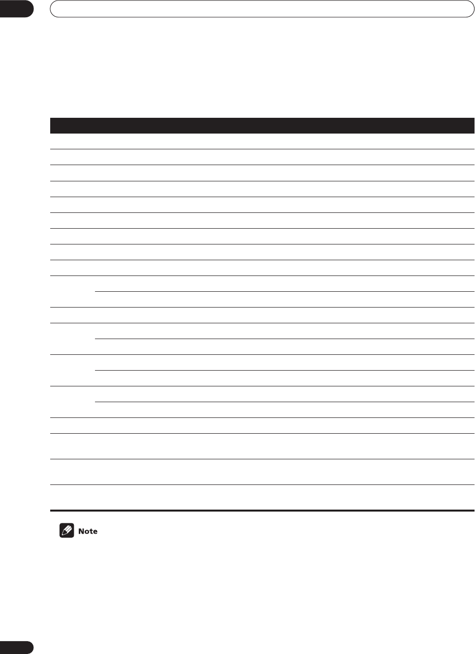
Controlling other equipment
08
56
En
Controls for TVs
This remote control can control components after entering the proper codes or teaching the receiver the commands
(see
Using the remote control with other components
on page 54 for more on this). Use the
MULTI CONTROL
buttons
to select the component.
• The
TV CONTROL
buttons on the remote control are dedicated to control the TV assigned to the
TV CONT
button.
Thus if you only have one TV to hook up to this system assign it to the
TV CONT MULTI CONTROL
button. If you
have two TVs, assign the main TV to the
TV CONT
button.
•Depending on the maker and individual model, there are some buttons that may not be able operate some equip-
ment or may operate it in a different way.
Button (s) Function Components
TV
Switches the TV, Satellite TV or Cable TV between standby and on. Cable TV/Satellite TV/TV
TV INPUT
Switches the TV input. TV
TV CH (+/ -)
Selects channels Cable TV/Satellite TV/TV
TV VOL (+/ -)
Adjusts the TV volume. TV
MENU
Takes you to the TV menu of that system. Cable TV/Satellite TV/TV/ Digital TV
GUIDE
Takes you to the guide menu of that system. Cable TV/Satellite TV/TV/ Digital TV
RETURN
Exits the current menu. Cable TV/Satellite TV/ Digital TV
A/BLUE Satellite TV/Digital TV/TV
B/Press to switch the DTV ON. Satellite TV/Digital TV/TV
C/GREEN Satellite TV/Digital TV/TV
Use to go to the previous page in a menu. Cable TV
D/RED Satellite TV/Digital TV/TV
E/YELLOW Satellite TV/Digital TV/TV
Use to go to the next page in a menu. Cable TV
Use to move back channels. Digital TV/TV/Cable TV
Use to move back a page in a menu. Satellite TV
Use to move forward channels. Digital TV/TV/Cable TV
Use to go to the next page in a menu. Satellite TV
Use to show the DTV menu. Digital TV/TV
Number
buttons
Use to select a specific TV channel. Cable TV/Satellite TV/TV/ Digital TV
ENTER/
DISC
Use this button to immediately enter a new channel. Cable TV/TV/Digital TV
&
ENTER
Press to select or adjust and navigate items on the menu screen. Cable TV/Satellite TV/TV/ Digital TV
VSX-9300.book 56 ページ 2004年5月21日 金曜日 午前11時28分
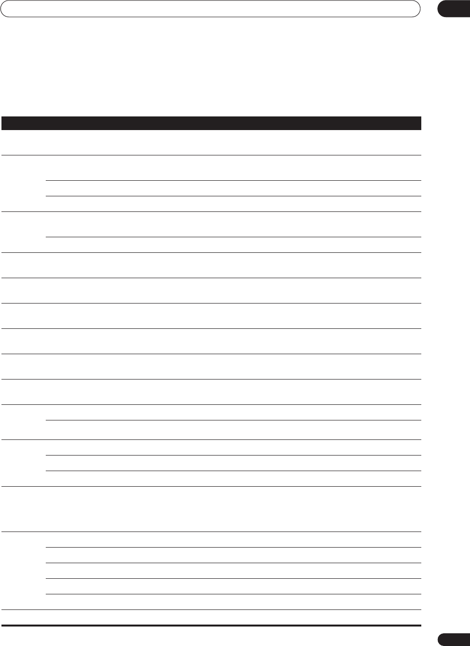
Controlling other equipment 08
57
En
Controls for other components
This remote control can control these components after entering the proper codes or teaching the receiver the
commands (see
Using the remote control with other components
on page 54 for more on this). Use the
MULTI
CONTROL
buttons to select the component.
Button(s) Function Components
SOURCE
Press to switch the component between standby and on. CD/MD/CD-R/VCR/DVD/LD/DVD
recorder/Cassette deck
Press to return to the start of the current track or chapter.
Repeated presses skips to the start of previous tracks or chapters. CD/MD/CD-R/DVD/LD
Use to move back channels (channel –). VCR/DVD recorder
Play the reverse side of the tape on a reversible deck. Cassette deck
Skips to the start of the next track or chapter.
Repeated presses skips to the start of following tracks or chapters. CD/MD/CD-R/DVD/LD
Use to go forward channels (channel +). VCR/DVD recorder
Pauses playback or recording. CD/MD/CD-R/VCR/DVD/LD/DVD
recorder/Cassette deck
Hold down for fast forward playback. CD/MD/CD-R/VCR/DVD/LD/DVD
recorder/Cassette deck
Hold down for fast reverse playback. CD/MD/CD-R/VCR/DVD/LD/DVD
recorder/Cassette deck
Start playback. CD/MD/CD-R/VCR/DVD/LD/DVD
recorder/Cassette deck
Stop playback (on some models, pressing this when the disc is already
stopped will cause the disc tray to open).
CD/MD/CD-R/VCR/DVD/LD/DVD
recorder/Cassette deck
Starts recording. MD/CD-R/VCR/DVD recorder/Cas-
sette deck
SUBTITLE/
DISP
MODE
Displays/changes the subtitles on multilingual DVDs. DVD/DVD recorder
Change the display mode. CD/MD/CD-R/VCR/LD
Number
buttons
Use to directly access tracks on a program source. CD/MD/CD-R/LD
Use to directly access chapters on a program source. DVD/DVD recorder
Use to directly select a channel. VCR/DVD recorder
+10 button
Use to select tracks or chapters higher than 10.
Press this button and the remaining number to get the track or chapter
(
+10
button +
3
= track or chapter 13).
• Some components may operate differently.
CD/MD/CD-R/DVD/LD/ DVD
recorder
ENTER/
DISC
Press to start the search mode. DVD
Takes you to the disc navigator. DVD recorder
Changes between sides A & B of the disc. LD
Press to enter the selected channel. VCR
Selects a disc in a multi-disc CD player. CD
MENU
Displays menus for the current DVD, DVR or VCR you are using. DVD/DVD recorder/VCR
VSX-9300.book 57 ページ 2004年5月21日 金曜日 午前11時28分
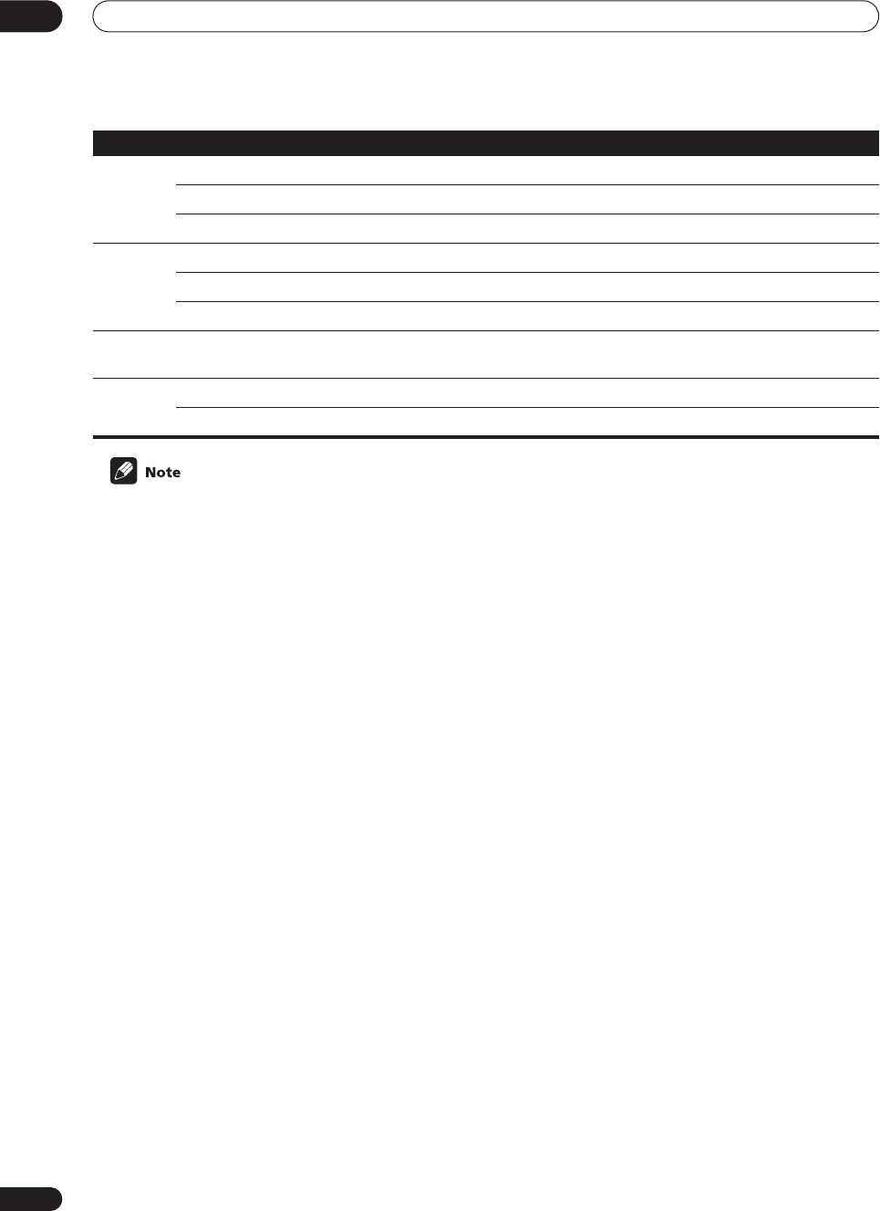
Controlling other equipment
08
58
En
• Depending on the maker and individual model, there are some buttons that may not be able operate some
equipment or may operate it in a different way.
• The default preset setting for all functions is a corresponding Pioneer component. Note that where two buttons
are listed, the first component is the the default (for example,
MD/TAPE2
is an MD), and the
VIDEO
button is set
to a Pioneer DVD player.
AUDIO
Changes the audio track of discs with more than one audio track. DVD/LD/DVD recorder
Changes between the tuner in the TV and the tuner in the VCR. VCR
Play the reverse side of the tape on a reversible cassette deck. Double cassette 2nd deck
TOP
MENU/
GUIDE
Displays the top menu of the current DVD, LD or DVR you are using. DVD/LD/DVD recorder
Takes you to the guide menu of the system. VCR
Press to select a track. CD
RETURN/
EXIT
Takes you to the previous menu. VCR/DVD/LD/DVD recorder
&
ENTER
Navigates menu/options. VCR/DVD/LD/DVD recorder
Basic playback options. Double cassette 2nd deck
Button(s) Function Components
VSX-9300.book 58 ページ 2004年5月21日 金曜日 午前11時28分
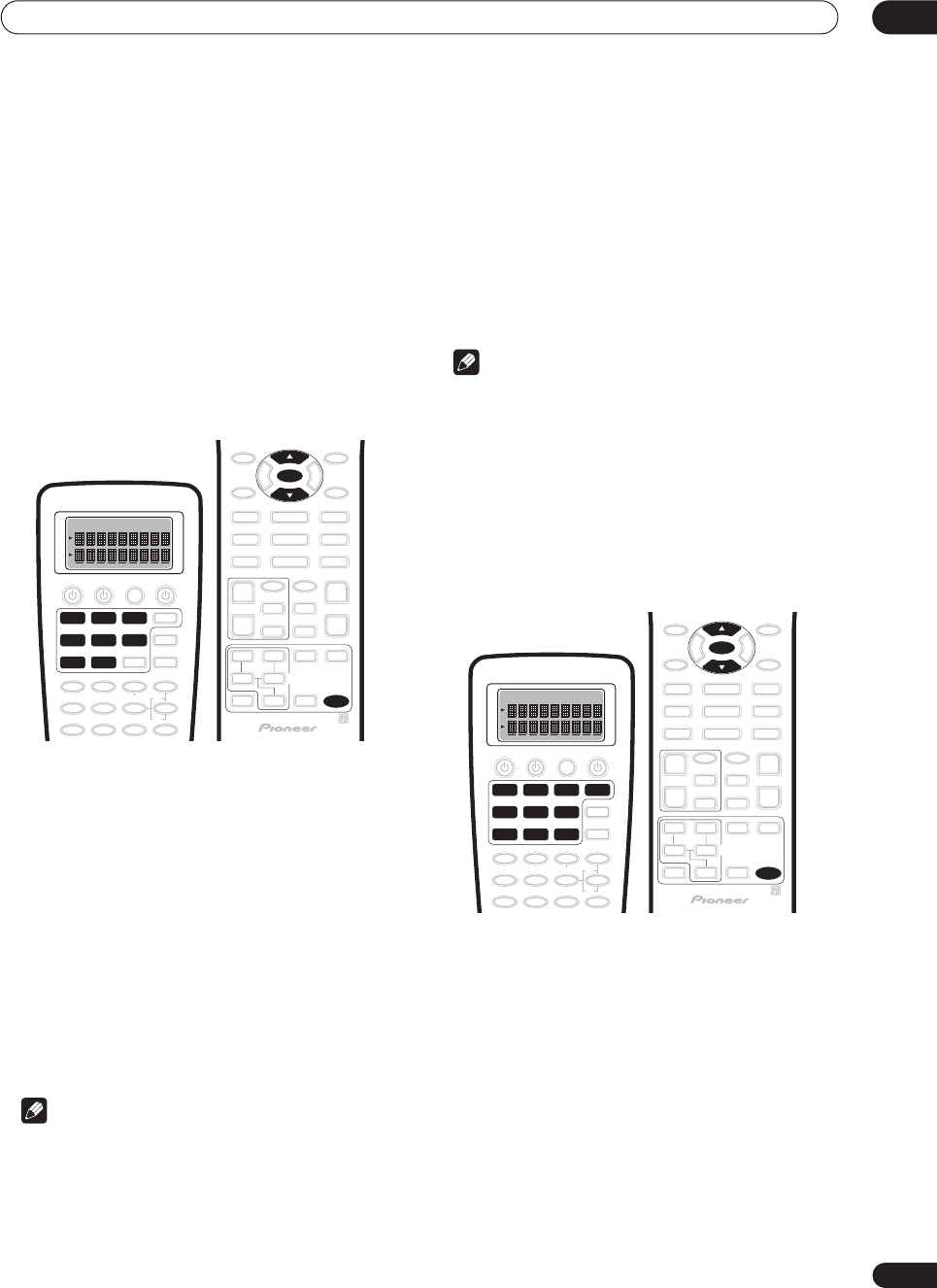
Controlling other equipment 08
59
En
Direct function
• Default setting:
On
(all components)
You can use the direct function feature to control one
component using the remote control while at the same
time, using your receiver to playback a different compo-
nent. This could let you, for example, use the remote
control to set up and listen to a CD on the receiver and
then use the remote control to rewind a tape in your VCR
while you continue to listen to your CD player.
When direct function is on, any component you select
(using the
MULTI CONTROL
buttons) will be selected by
both the receiver and the remote control. When you turn
direct function off, you can operate the remote control
without affecting the receiver.
1Press and hold REMOTE SETUP for three seconds.
The
REMOTE SETUP
menu appears on the remote
control display.
2 Use
/
(cursor up/down) to select ‘DirctFnc’
from the menu and press ENTER.
Select Function
flashes in the display.
3Press the MULTI CONTROL button for the compo-
nent you want to set.
The remote displays the component you want to set.
4 Use
/
(cursor up/down) to switch direct func-
tion on or off then press ENTER.
The display shows
COMPLETE
to confirm the setting.
5Repeat steps 2–4 for as many components as you
want.
Note
• You can’t use direct function with the
TUNER
or
TV
CONT
functions.
Multi Operation and System Off
The Multi Operation feature allows you to program a
series of commands for the components in your system.
For example, you could turn on your TV, turn on your DVD
player and start playing the loaded DVD using only two
buttons on the remote control.
Similar to multi operations, System Off allows you to use
one button to stop and switch off a series of components
in your system at the same time.
Note
• Before Multi Operation and System Off will work
correctly, you must setup the remote to work with
your TV and other components (see
Recalling preset
codes
on page 54 and
Programming signals from
other remote controls
on page 55 for more on this).
• Power on and off commands only work with
components that have a standby mode.
Programming a multi-operation or a
shutdown sequence
1Press and hold REMOTE SETUP for three seconds.
The
REMOTE SETUP
menu appears on the remote
control display.
2 Use
/
(cursor up/down) to select ‘MultiOpe’ or
‘SysOff’ from the menu and press ENTER.
If you selected Multi Operation
(
MultiOpe
),
Select
Function
flashes in the display.
If you selected System Off
(
SysOff
),
System Off
appears
in the display. Go to step 4.
3 Press the MULTI CONTROL button for the
component you want to start the multi-operation.
Multi Ope
appears in the display.
DVD/LD
VCR2 VIDEO CD
TV/SAT
MULTI CONTROL
VCR1 /
DVR
CD-R/
TAPE1
MD/
TAPE2
REMOTE
SETUP
ENTER
DVD/LD
VCR2 VIDEO CD
TV/SAT
MULTI CONTROL
VCR1 /
DVR
CD-R/
TAPE1
MD/
TAPE2
TUNER
TV CONT
REMOTE
SETUP
ENTER
VSX-9300.book 59 ページ 2004年5月21日 金曜日 午前11時28分
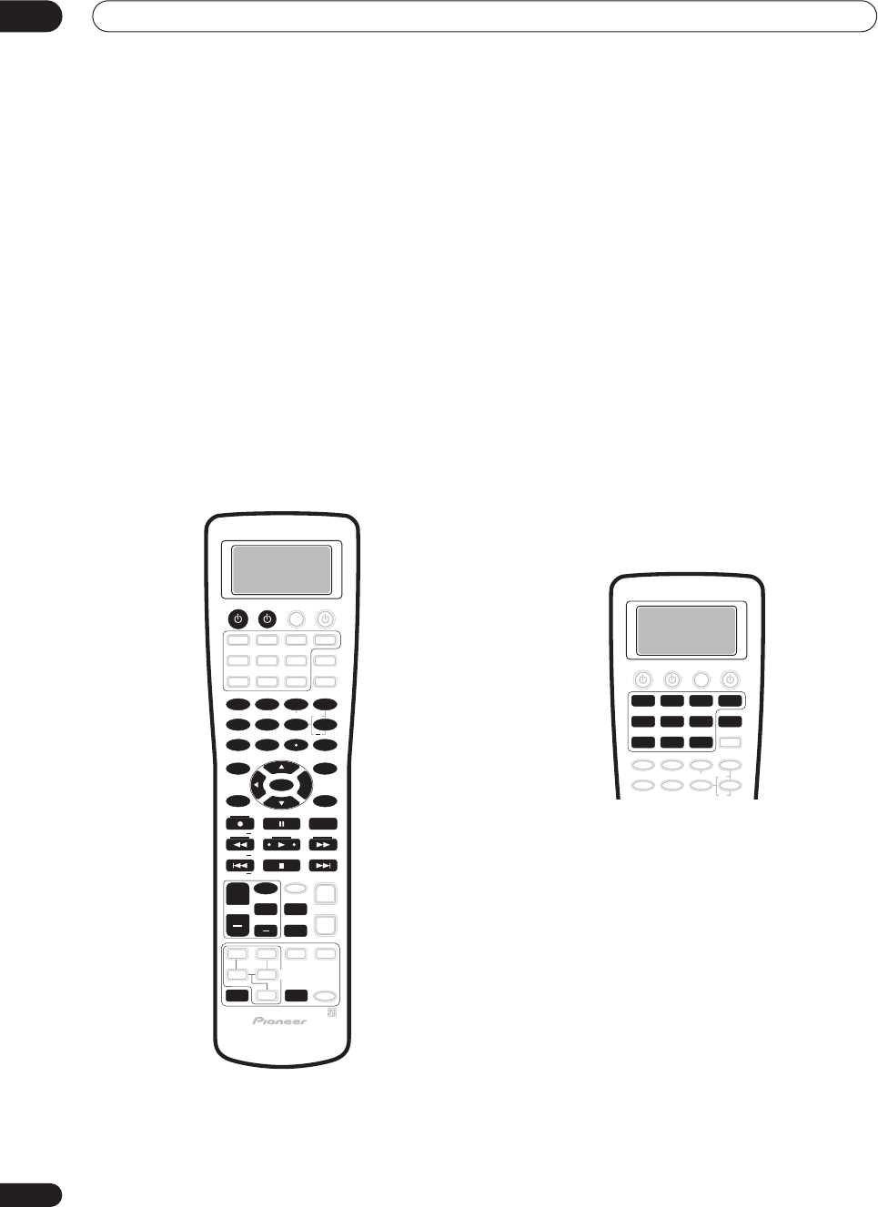
Controlling other equipment
08
60
En
4 Use
/
(cursor up/down) to select a command
in the sequence then press ENTER.
If this is the first command in the sequence, select
1st
Cmmnd
. Otherwise, simply choose the next command in
the sequence.
5 To add (or change) a command select ‘Change’
and press ENTER.
Function
flashes in the display.
•To erase a command select
Clear
and press
ENTER
.
You will return to the last step.
• To go back a step, select
*Exit*
and press
ENTER
.
6 Press the MULTI CONTROL button for the
component whose command you want to input.
Key
flashes in the display.
7Select the button for the command you want to
input.
The following remote control commands can be
selected:
• After selecting a command,
COMPLETE
appears in
the display.
8Repeat steps 4–7 to program a sequence of up to
five commands.
•You don't need to program the receiver to switch on
or off. This is done automatically.
With Pioneer components
, you don’t need to:
• program the power to switch off in a shutdown
sequence;
• program the power to switch on if it’s the source
component selected in step 3;
• program a Pioneer TV or monitor to switch on if the
input function (selected in step 2) has video input
terminals;
These take priority in multi operations (not shutdown).
9When you’re finished, use
/
(cursor up/down)
to select ‘*Exit*’ from the menu and press ENTER.
You will return to the
REMOTE SETUP
menu. Select
*Exit*
again to exit.
Using multi operations
You can start multi operations with the receiver switched
on, or in standby.
1 Press MULTI OPERATION.
Select Function
flashes in the display.
2Press a function button that has been set up with
a multi operation.
The receiver switches on (if it was in standby) and the
programmed multi operation is performed automatically.
SOURCE
DIMMER
LOUDNESS TONE
SIGNAL SEL
DNR
DISC
1
5
90
678
342
BASS/TREBLE
VIDEO SEL
HI-BIT
DIRECT ACCESS
SEARCH MODE
ENTER
GUIDE
SYSTEM SETUP
TUNER EDIT
MPX
TUNING BAND
DTV ON/OFF DISP MODE
TUNING
STATION DTV MENU CLASS STATION
CHANNEL
SUB TITLE
ENTER
TOP MENU
MENU
AUDIO
RETURN
TRACK
EXIT
+
10
+
+
+
CHANNEL
+
EFFECT/CH SEL
TV
TV VOL
TV CONTROL
TV CH
TV INPUT
MIDNIGHT
MULTI DH
INPUT
SB CH
MODE
STEREO/
DIRECT
+
+
DVD/LD
VCR2 VIDEO CD
TV/SAT
TV CONT
MULTI CONTROL
VCR1 /
DVR
CD-R/
TAPE1
MD/
TAPE2
MULTI
OPERATION
TUNER
VSX-9300.book 60 ページ 2004年5月21日 金曜日 午前11時28分
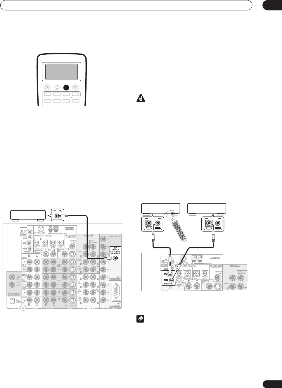
Controlling other equipment 08
61
En
Using System off
• Press SYSTEM OFF.
The command sequence you programmed will run, then
all Pioneer components will switch off, followed by this
receiver.
Switching components on and off
using the 12 volt trigger
You can connect components in your system (such as a
screen or projector) to this receiver so that they switch on
or off using a 12 volt trigger when you select an input
function. However, you must specify which input
functions switch on the trigger using the System Setup
menu (see
12 Volt Trigger
on page 78 to do this). Note that
this will only work with components that have a standby
mode.
•Connect the 12V TRIGGER jack of this receiver to
the 12V TRIGGER of another component.
Use a cable with a mono mini-plug on each end for the
connection.
• The trigger maximum power is DC OUT 12V/100mA.
After you’ve specified the input functions that will switch
on the trigger, you’ll be able to switch the component on
or off just by pressing the input function(s) you’ve set on
page 78.
Operating other Pioneer components
with this unit’s sensor
Many Pioneer components have SR
CONTROL
jacks
which can be used to link components together so that
you can use just the remote sensor of one component.
When you use a remote control, the control signal is
passed along the chain to the appropriate component.
Important
• Note that if you use this feature,
make sure that you
also have at least one set of analog audio or video jacks
connected
to another component for grounding
purposes.
1 Decide which component you want to use the
remote sensor of.
When you want to control any component in the chain,
this is the remote sensor at which you’ll point the
corresponding remote control.
2Connect the CONTROL OUT jack of that
component to the CONTROL IN jack of another
Pioneer component.
Use a cable with a mono mini-plug on each end for the
connection.
3Continue the chain in the same way for as many
components as you have.
Note
•If you want to control all your components using this
receiver’s remote control, refer to
Using the remote
control with other components
on page 54 and
Programming signals from other remote controls
on
page 55.
• If you have connected a remote control to the
CONTROL IN
jack (using a mini-plug cable), you
won't be able to control this unit using the remote
sensor.
SYSTEM
OFF
CENTER
12V
TRIGGER
VSX-9300TX
CENTER
IN OUT
CONTROL
VSX-9300TX
IN OUT
CONTROL
VSX-9300.book 61 ページ 2004年5月21日 金曜日 午前11時28分
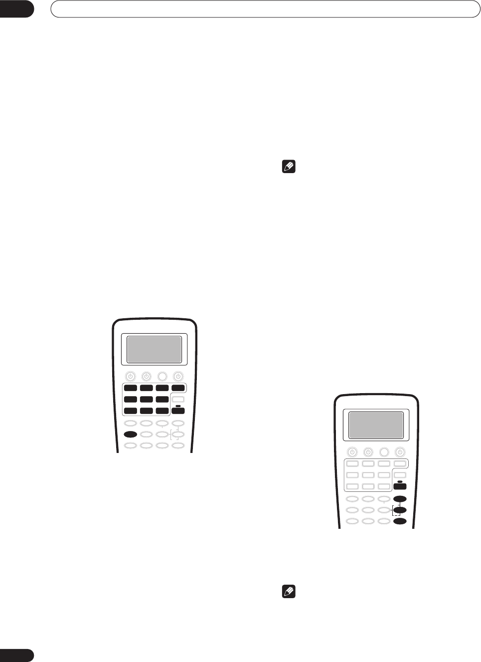
Using other functions
09
62
En
Chapter 9
Using other functions
Making an audio or a video recording
You can make an audio or a video recording from the
built-in tuner, or from an audio or video source
connected to the receiver (such as a CD player or TV).
Keep in mind you can't make a digital recording from an
analog source or vice-versa, so make sure the
components you are recording to/from are hooked up in
the same way (see
Connecting your equipment
on
page 15 for more on connections).
Note that when recording video, you won’t be able to
record sources connected to the component video
inputs. With composite and S-video sources, make sure
they are connected using the same type of video cable as
you used to connect the recorder to the receiver.
For more information about video connections, see
Connecting a VCR or DVD recorder
on page 22 and
Connecting other video sources
on page 23.
1 Select the source you want to record.
Use the
MULTI CONTROL
buttons (or the
MULTI JOG
dial on the front panel).
2 Select the input signal (if necessary).
Press
SIGNAL SEL
to select the input signal
corresponding to the source component (see
Selecting
the input signal type
on page 42 for more on this).
3 Prepare the source you want to record.
Tune to the radio station, load the CD, video, DVD etc.
4 Prepare the recorder.
Insert a blank tape, MD, video etc. into the recording
device and set the recording levels.
Refer to the instructions that came with the recorder if
you are unsure how to do this. Most video recorders set
the audio recording level automatically—check the
component's instruction manual if you're unsure.
5Start recording, then start playback of the source
component.
Note
•The receiver's volume, tone (bass, treble, Midnight,
Loudness), and surround effects have no effect on
the recorded signal. (The exception to this is
PHONO
,
which is best recorded using stereo
DIRECT
.)
• Some digital sources are copy-protected, and can
only be recorded in analog.
• Some video sources are copy-protected. These
cannot be recorded.
Adjusting the delay of a soundtrack
• Default setting:
0.0 frame
Some monitors have a slight delay when showing video,
so the soundtrack will be slightly out of sync with the
picture. By adding a bit of delay, you can adjust the sound
to match the presentation of the video.
1Press RECEIVER.
2 Press EFFECT/CH SEL repeatedly until DELAY
shows in the display.
3 Use the +/– buttons to adjust the amount of
delay.
The delay can be adjusted from 0.0–6.0 frames (in 0.1
frame steps).
Note
• One second is equal to 30 frames of NTSC format.
• This setting is applied to all video sources.
• You can’t use sound delay when
MULTI CH IN
or
DIRECT
is switched on.
DVD/LD
VCR2 VIDEO CD
TV/SAT
TV CONT
MULTI CONTROL
VCR1 /
DVR
CD-R/
TAP E 1
MD/
TAPE2
TUNER
SIGNAL SEL
RECEIVER
+
EFFECT/CH SEL
RECEIVER
VSX-9300.book 62 ページ 2004年5月21日 金曜日 午前11時28分
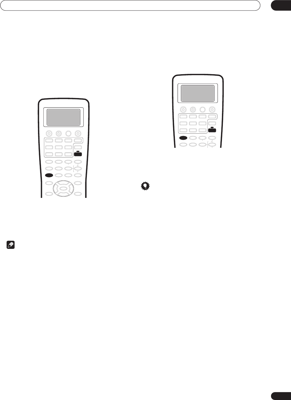
Using other functions 09
63
En
Watching video and audio sources
independently
You can listen to a sound source and select a different
video source on your TV.
•While listening to a source, press RECEIVER, then
VIDEO SEL to select the video source you want to
watch.
Press repeatedly to cycle through the possible video
sources. You can select
DVD/LD
,
TV/SAT
,
VIDEO
,
VCR1/DVR
,
VCR2
or
OFF
(no video signal).
•Selecting any input besides those listed above is the
same as selecting
OFF
.
Note
•If you change the source using the
MULTI CONTROL
buttons (or the
MULTI JOG
dial on the front panel), or
switch the power off, the system returns to normal
playback.
Dimming the display
You can choose between four brightness for the front
panel display. Note that when selecting sources, the
display automatically brightens for a few seconds.
1Press RECEIVER.
2 Press DIMMER repeatedly to change the
brightness of the front panel display.
Tip
• Switching the dimmer to lowest setting will also
switch off the MCACC indicator.
VIDEO SEL
RECEIVER
RECEIVER
DIMMER
VSX-9300.book 63 ページ 2004年5月21日 金曜日 午前11時28分
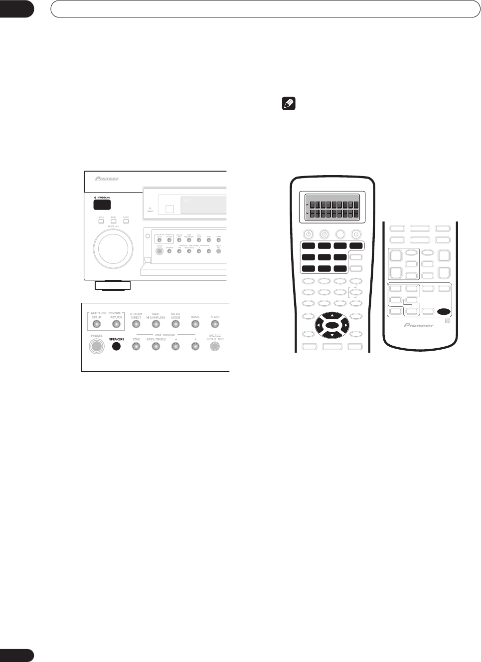
Using other functions
09
64
En
Switching the speaker impedance
• Default setting:
Speaker 8
ΩΩ
ΩΩ
You can use speakers with a nominal impedance
between 6–16
Ω
but if you are using speakers with an
impedance of less than 8
Ω
, you must change the
impedance setting below.
• With the receiver in standby, press
STANDBY/
ON while holding down the SPEAKERS button.
Each time you do this, you switch between the
impedance settings:
•
Speaker 6
ΩΩ
ΩΩ
– Use this setting if your speakers are
rated lower than 8
Ω
(down to 6
Ω
).
•
Speaker 8
ΩΩ
ΩΩ
– Use this setting if your speakers are
rated 8
Ω
–16
Ω
.
Advanced remote control features
Note
• You can cancel or exit any of the following steps by
pressing
REMOTE SETUP
.
• After one minute of inactivity, the remote goes to
sleep. Press any button to reactivate the remote
display and continue.
Editing remote control display names
You can rename what appears in the display on the
remote control for the
MULTI CONTROL
buttons (such
as
DVD/LD
or
TV/SAT
), or for individual buttons for each
input source. You may want to do this if the component
connected to the inputs doesn’t correspond to the
MULTI CONTROL
button name, or individual commands
don’t correspond to their respective buttons.
1Press and hold REMOTE SETUP for three seconds.
The
REMOTE SETUP
menu appears in the remote control
display.
2 Use
/
(cursor up/down) to select ‘FuncName’
or ‘Key Label’ from the menu and press ENTER.
Select Function Name
(
FuncName
) if you want to rename
a
MULTI CONTROL
button.
Select Key Label
(
KeyLabel
) if you want to rename a
command button (you can rename individual command
buttons for each input source).
Select Function
flashes in the display.
3 Press the MULTI CONTROL
button for the
component.
If you selected Function Name
(
FuncName
) above, go to
step 5.
If you selected Key Label
(
KeyLabel
) above,
Select Key
flashes in the display.
DVD/LD
VCR2
ENTER
VIDEO CD
TV/SAT
TV CONT
MULTI CONTROL
VCR1 /
DVR
CD-R/
TAPE1
MD/
TAPE2
TUNER
REMOTE
SETUP
VSX-9300.book 64 ページ 2004年5月21日 金曜日 午前11時28分

Using other functions 09
65
En
4 Press the button you want to rename.
5 Edit the button as necessary.
Use
/
(cursor up/down) to select letters and/or
numbers and use
/
(cursor left/right) to move the
cursor forward/back a position. The name can be up to
eight characters (the possible characters are listed
below).
ABCDEFGHIJKLMNOPQRSTUVWXYZ
abcdefghijklmnopqrstuvwxyz
0123456789 (space)
!”#$%&’()*+,–./:;<=>?@[ \ ]^_`{|}~
|
· (space)
6 When you're finished press ENTER.
When you see
END
flash, press
ENTER
again.
COMPLETE
shows in the display to confirm that the
name has been changed.
• Go back to step 2 to edit more names.
7When you’re finished, use
/
(cursor up/down)
to select ‘*Exit*’ from the menu and press ENTER.
Adjusting the remote control backlight
You can adjust the brightness of the backlight on the
remote control display, or simply switch it off.
1Press and hold REMOTE SETUP for three seconds.
The
REMOTE SETUP
menu appears in the remote control
display.
2 Use
/
(cursor up/down) to select ‘Light’ from
the menu and press ENTER.
3 Use
/
(cursor up/down) to select ‘High’, ‘Low’
or ‘Off’ and press ENTER.
COMPLETE
appears in the display to confirm the setting.
4When you’re finished, use
/
(cursor up/down)
to select ‘*Exit*’ from the menu and press ENTER.
Clearing remote control settings
This feature allows you to clear a learned command or
key label for a particular button, or all of the settings from
the remote.
1Press and hold REMOTE SETUP for three seconds.
The
REMOTE SETUP
menu appears in the remote control
display.
2 Use
/
(cursor up/down) to select ‘Clear’ from
the menu and press ENTER.
CLEAR
appears in the display.
3 Use
/
(cursor up/down) to select what you
want to clear, and press ENTER.
Choose between the following:
•
Learning Clear
– Clear a learned command (see
Programming signals from other remote controls
on
page 55) you have assigned to a button (
Select
Function
flashes in the display).
•
KeyLabel Clear
– Clear a name (see
Editing remote
control display names
above) you have assigned to a
button (
Select Function
flashes in the display).
•
All Clear
– Clear all custom settings you have made
with the remote (
CLEAR?
shows in the display). Go to
step 6.
4 Press the MULTI CONTROL button of the
component for which you want to clear a command
or key label.
Select Key
flashes in the display.
5 Press the button you want to clear.
The button you selected, then
CLEAR?
appears in the
display.
6 Use
/
(cursor up/down) to select ‘Yes’ and
press ENTER.
COMPLETE
appears in the display.
• Select
No
or
*Exit*
to exit and return to the
REMOTE
SETUP
menu.
7When you’re finished, use
/
(cursor up/down)
to select ‘*Exit*’ from the menu and press ENTER.
VSX-9300.book 65 ページ 2004年5月21日 金曜日 午前11時28分
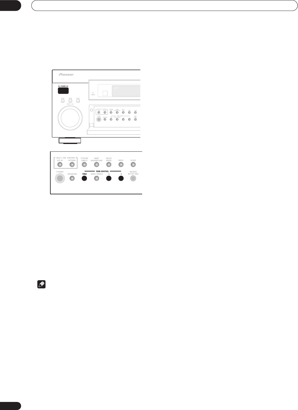
Using other functions
09
66
En
Resetting the system
Use this feature to reset the system to its factory default
settings.
1 Switch the receiver into standby.
2 While holding down the front panel TONE
button, press and hold
STANDBY/ON for about
three seconds.
The display shows
RESET?
.
3 Press the front panel TONE– button.
The display shows
OK?
.
4 Within 5 seconds, press TONE+.
The display shows
OK
and the receiver should now be
reset.
Note
• Make sure the multi-room feature is switched off
when doing this.
• If the receiver is unplugged from the AC outlet for a
month or more, it resets to the default settings.
VSX-9300.book 66 ページ 2004年5月21日 金曜日 午前11時28分
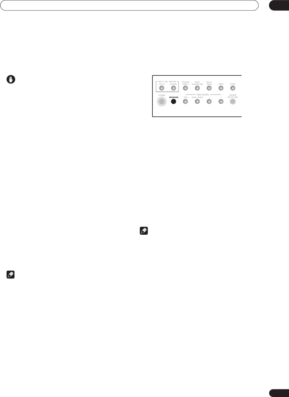
Other connections 10
67
En
Chapter 10
Other connections
Caution
•
Before making or changing the connections
, switch off
the power and disconnect the power cord from the
power outlet. Plugging in components should be the
last connection you make with your system.
•Be careful not to allow any contact between speaker
wires from different terminals.
• You can use speakers with a nominal impedance
between 6–16
Ω
(please see
Switching the speaker
impedance
on page 64 if you plan to use speakers
with an impedance of less than 8
Ω
).
Second Zone speaker B setup
After selecting
Second Zone
in
Surround back speaker
setting
on page 51, you can use the speakers connected
to the (surround back) B speaker terminals on the rear
panel to listen to stereo playback in another room. See
Switching the speaker system
below for the listening
options with this setup.
1Connect a pair of speakers to the surround back
speaker terminals on the rear panel.
Connect them the same way you connected your
speakers in
Connecting the speakers
on page 29. Make
sure to review
Placing the speakers
on page 29 when
placing the speakers in another room.
2Select ‘Second Zone‘ from the ‘SurrBack System’
menu.
See
Surround back speaker setting
on page 51 to do this.
Note
• You can also use the multi-room feature to listen to
stereo playback in another room. See
Multi-room
listening
on page 69 for more on this.
Switching the speaker system
If you selected
Second Zone
in
Surround back speaker
setting
on page 51, three speaker system settings are
possible using the
SPEAKERS
button. If you selected
Normal Surround
, the button will simply switch your
main speaker system on or off. The options below are for
the
Second Zone
setting only
• Use the SPEAKERS button on the front panel to
select a speaker system setting.
As mentioned above, if you have selected
Normal
Surround
, the button will simply switch your main
speaker system (A) on or off.
Press repeatedly to choose a speaker system option:
•
SP
A
– Sound is output from speaker system A and
the same signal is output from the pre-out terminals.
•
SP
B
– Sound is output from the two speakers
connected to speaker system B. Multichannel
sources will not be heard.
•
SP
AB
– Sound is output from speaker system A (up
to 5 channels, depending on the source), the two
speakers in speaker system B. The sound from
speaker system B will be the same as the sound from
speaker system A (multichannel sources will be
downmixed to 2 channels).
•
SP
(off) – No sound is output from the speakers. The
same sound is output from the pre-out terminals as
when selecting speaker system A (above).
Note
• The subwoofer output depends on the settings you
made in
Normal surround setting
on page 51.
However, if
SP
B
is selected above, no sound is
heard from the subwoofer (the LFE channel is not
downmixed).
• Depending on the settings in
Normal surround
setting
on page 51 and
Listening with Acoustic
Calibration EQ
on page 41, output from the surround
back pre-out terminals may change.
• Some sources (for example, when
MULTI CH IN
is
selected) will not be downmixed.
• All speaker systems are switched off when
headphones are connected.
VSX-9300.book 67 ページ 2004年5月21日 金曜日 午前11時28分
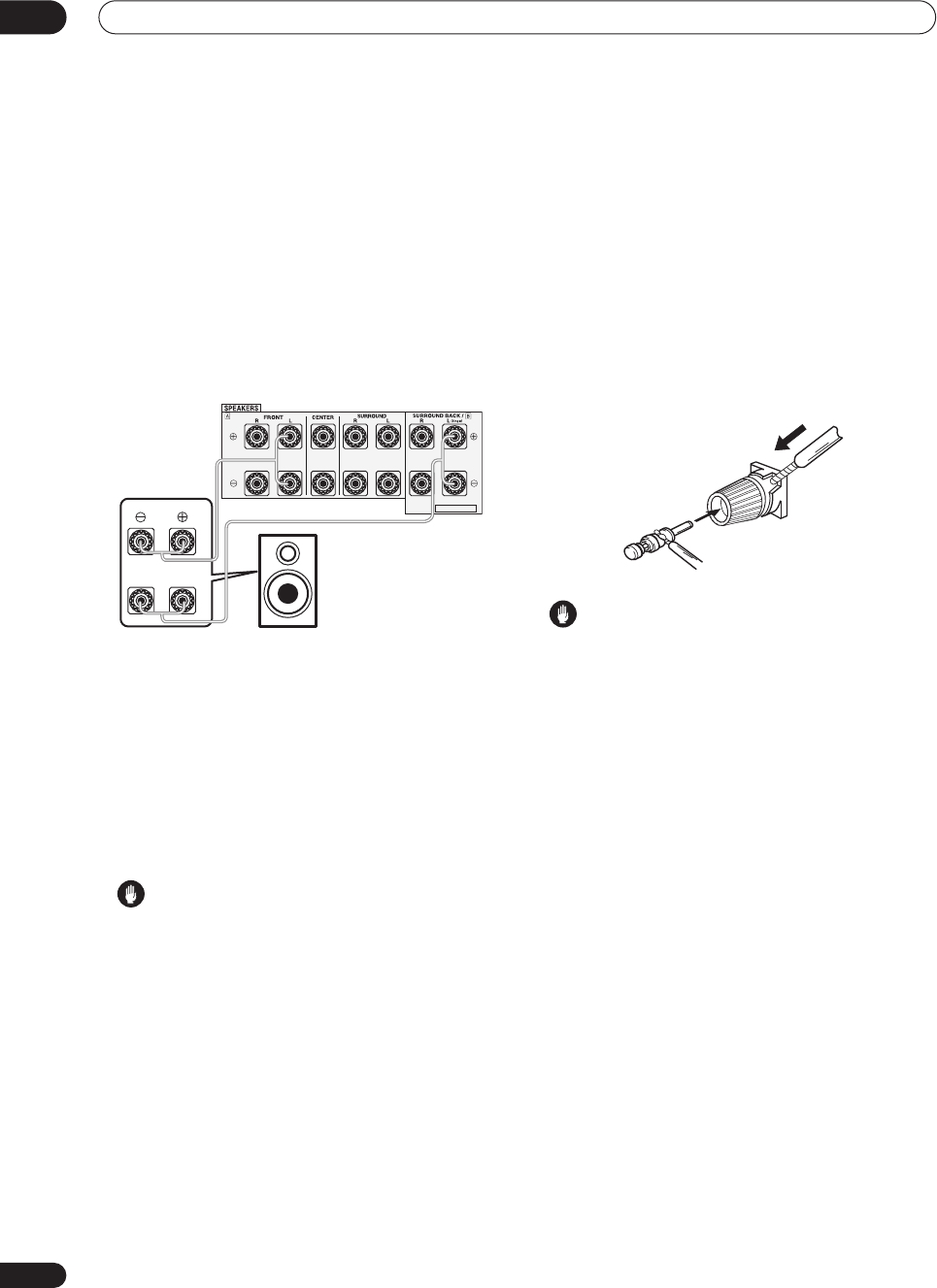
Other connections
10
68
En
Bi-amping your front speakers
Bi-amping is when you connect the high frequency driver
and low frequency driver of your speakers to different
amplifiers (in this case, to both front and surround back
terminals) for better crossover performance. Your
speakers must be bi-ampable to do this (having separate
terminals for high and low) and the sound improvement
will depend on the kind of speakers you’re using.
1 Connect your speakers as shown below.
This illustration below shows the connections for bi-
amping your front left speaker. Hook up your front right
speaker in the same way.
Since both front and surround back speaker terminals
output the same audio, it doesn’t matter which set (front
or surround back) is powering which part (
Hi
or
Low
) of
the speaker.
• Make sure that the
+
/
–
connections are properly
inserted.
2 Select the ‘Front Bi-Amp’ setting from the
‘SurrBack System’ menu.
See
Surround back speaker setting
on page 51 to specify
how you’re using the surround back speaker terminals.
Caution
•Most speakers with both
Hi
and
Low
terminals have
two metal plates that connect the
Hi
to the
Low
terminals. These must be removed when you are bi-
amping the speakers or you could severely damage
the amplifier. See your speaker manual for more
information.
•If your speakers have a removable crossover network,
make sure you do not remove it for bi-amping. Doing
so may damage your speakers.
Bi-wiring your speakers
The reasons for bi-wiring are basically the same as bi-
amping, but additionally, interference effects within the
wire could be reduced, producing better sound. Again, to
do this your speakers must be bi-wireable (that is they
must have separate terminals for the high and low
frequencies). When bi-wiring, make sure you’ve selected
Normal Surround
in
Surround back speaker setting
on
page 51.
•To bi-wire a speaker, connect two speaker cords
to the speaker terminal on the receiver.
Using a banana plug for the second connection is
recommended.
Caution
• Make sure you use a parallel (not series, which are
fairly uncommon) connection when bi-wiring your
speakers.
• Don't connect different speakers from the same
terminal in this way.
SELECTABLE
Hi
Lo
Front left
speaker
VSX-9300.book 68 ページ 2004年5月21日 金曜日 午前11時28分
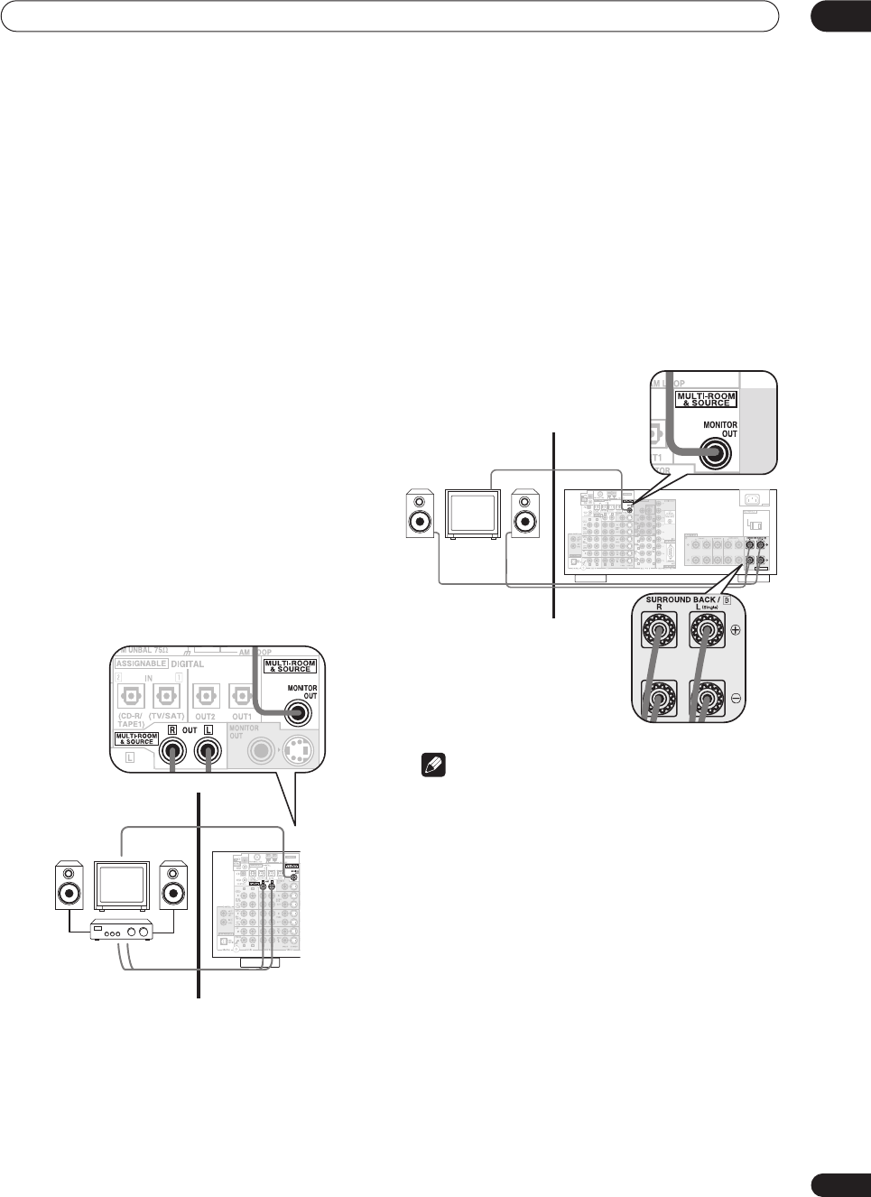
Other connections 10
69
En
Multi-room listening
This receiver can power two independent systems in
separate rooms after you have made the proper multi-
room connections. Different sources can be playing in
both rooms at the same time or, depending on your
needs, the same source can also be used. The main and
sub rooms have independent power (the main room
power can be off while the sub room is on) and the sub
room can be controlled by the front panel controls.
However, you may need to specify the volume setting in
Multi-Room and IR receiver setup
on page 78.
Making multi-room connections
It is possible to make these connections if you have a
separate TV and speakers for your sub room. You will also
need a separate amplifier if you are not using the
SurrBack System setup (see below). There are two multi-
room setups possible with this system:
Basic multi-room setup
• Connect a separate amplifier to the MULTI-
ROOM & SOURCE OUT jacks and a TV monitor to the
MULTI-ROOM & SOURCE MONITOR OUT jacks, both
on the rear of this receiver.
You should have a pair of speakers attached to the sub
room amplifier as shown in the illustration below.
SurrBack System multi-room setup
You must select
MR&S
in
Surround back speaker setting
on page 51 to use this setup. Note that the sound in the
sub room will be temporarily interrupted when
controlling the main room (for example, changing the
input source or starting playback).
• Connect a TV monitor to the MULTI-ROOM &
SOURCE MONITOR OUT jacks on the rear of this
receiver.
You should have a pair of speakers attached to the
surround back speaker terminals as shown in the
illustration below.
Note
• It is not possible to hear the digital output of a
component in the sub room. However, you can
connect the analog outputs of your digital
component into the receiver’s (analog) input
terminals to hear the component in the sub room.
• You can't use sound controls (such as the tone
controls or Midnight listening) or any surround
modes in the sub room. You can, however, use the
features available with your sub room amplifier.
Sub room Main room
C
C
Sub room Main room
AC IN
SWITCHED 100W(0.8A)MAX
SELECTABLE
CENTER
CENTER
VSX-9300.book 69 ページ 2004年5月21日 金曜日 午前11時28分
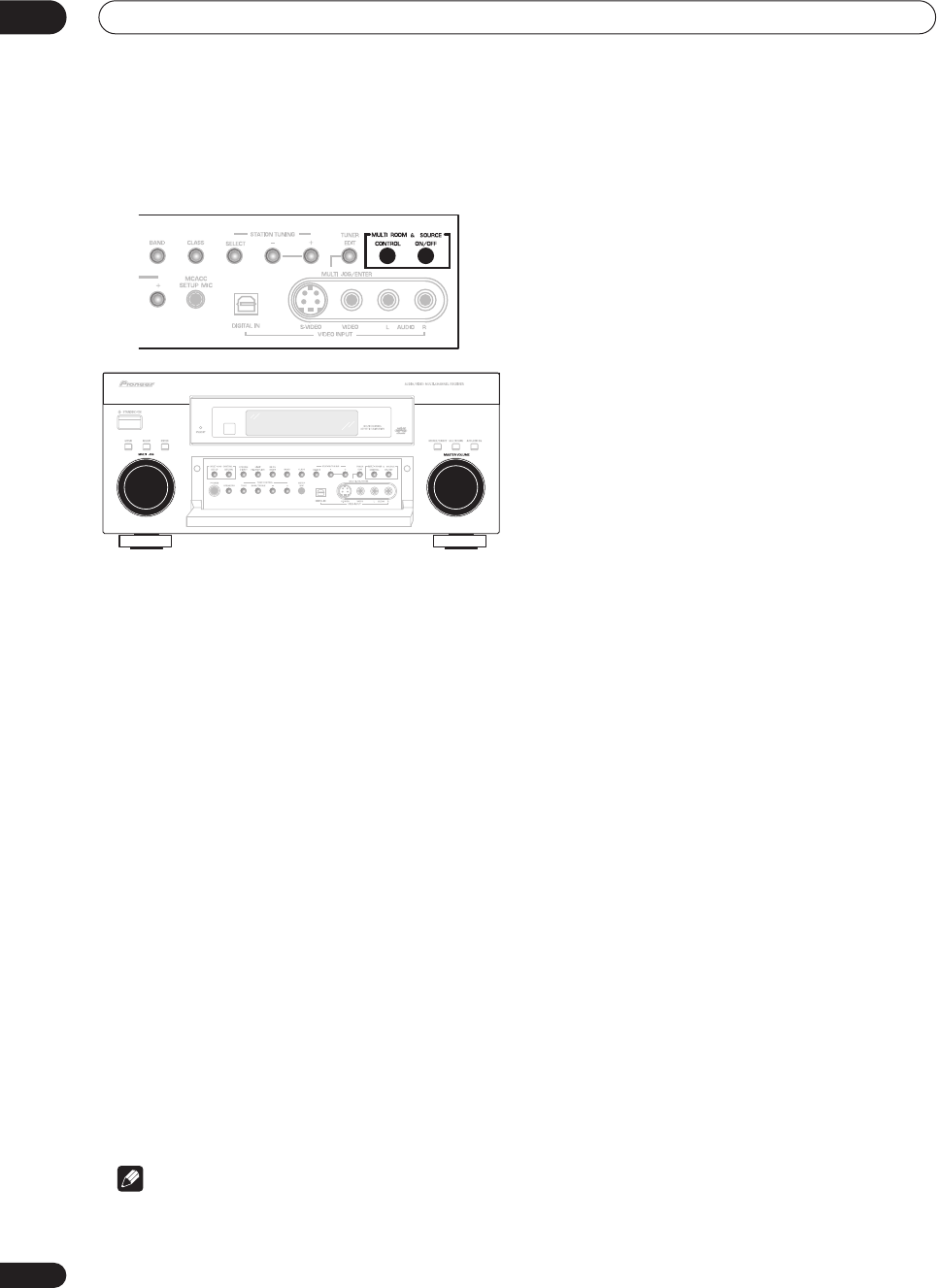
Other connections
10
70
En
Using the multi-room controls
You can use the front panel controls to adjust the sub
room volume and select sources.
1 Press the MULTI ROOM & SOURCE ON/OFF
button on the front panel.
The
MULTI ROOM
indicator lights and
MR&S ON
appears in the front panel display to indicate the multi-
room control has been switched on.
2 Press CONTROL.
Make sure that any operations for the sub room are done
while
MULTI-ROOM
shows in the display. If
MULTI-
ROOM
is not showing, the front panel controls affect the
main room only.
3 Use the MULTI JOG dial to select the source.
Select between
DVD/LD
,
TV/SAT
,
VCR 1/DVR
,
CD
,
CD-
R/TAPE 1
or
TUNER
(in that order).
• If you select
TUNER
, you can use the front panel
TUNER
controls to select a preset station (see
Listening to memorized station presets
on page 49 if
you’re unsure how to do this).
4 Use the MASTER VOLUME dial to adjust the
volume.
This is only possible if you selected the
VARIABLE
volume control in
Multi-Room and IR receiver setup
on
page 78.
5 When you’re finished, press CONTROL again to
return to the main room controls.
You can also press the
MULTI ROOM & SOURCE ON/
OFF
button on the front panel to switch off all output to
the sub room.
Note
•Multi-room can’t be used when you’re setting up the
system (from the on-screen
System Setup
menu).
• You won’t be able to switch the main room off
completely unless you’ve switched off the multi-room
control first.
• The tuner cannot be tuned to more than one station
at a time. Therefore, changing the station in one
room also changes the station in the other room.
Please be careful not to change stations when
recording a radio broadcast.
• The volume levels of the main and sub rooms are
independent.
• If you don’t plan to use the multi-room feature for
awhile, turn off the power in both the sub and main
rooms. Make sure the
STANDBY
indicator turns red
and the
MULTI-ROOM
indicator goes off.
VSX-9300TX
VSX-9300.book 70 ページ 2004年5月21日 金曜日 午前11時28分
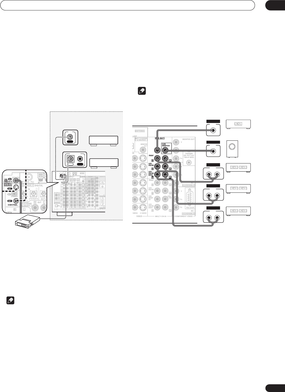
Other connections 10
71
En
Connecting an IR receiver
If you keep your stereo components in a closed cabinet or
shelving unit, you can use an optional IR receiver (such
as a Niles or Xantech unit) to control your system instead
of the remote sensor on the front panel of this receiver.
You may need to specify your IR receiver type in
Multi-
Room and IR receiver setup
on page 78.
1 Connect the IR receiver sensor to the MULTI-
ROOM & SOURCE IR IN jack on the rear of this
receiver.
2 Connect the IR IN jack of another component to
the MULTI-ROOM & SOURCE IR OUT jack on the rear
of this receiver to link it to the IR receiver.
Please see the manual supplied with your IR receiver for
the type of cable necessary for the connection.
• If you want to link a Pioneer component to the IR
receiver, see
Operating other Pioneer components
with this unit’s sensor
on page 61 to connect to the
CONTROL
jacks instead of the
IR OUT
jack.
Note
• Remote operation may not be possible if direct light
from a strong fluorescent lamp is shining on the IR
receiver remote sensor window.
• Note that other manufacturers may not use the IR
terminology. Refer to the manual that came with your
component to check for IR compatibility.
• If using two remote controls (at the same time), the
IR receiver’s remote sensor takes priority over the
remote sensor on the front panel.
Cnnecting additional amplifiers
This receiver has more than enough power for any home
use, but it’s possible to add additional amplifiers to every
channel of your system using the pre-outs. Make the
connections shown below to add amplifiers to power
your speakers.
Note
• Before making or changing the connections, switch
off the power and disconnect the power cord from the
AC outlet.
•You can use the additional amplifier on the surround
back channel pre-outs for a single speaker as well. In
this case plug the amplifier into the left (
L (Single)
)
terminal only.
• The sound from the surround back terminals will
depend on how you have configured the
Surround
back speaker setting
on page 51.
Closet or shelving unit
IR receiver
CENTER
Non-Pioneer
component
IN
IR
Pioneer
component
IN OUT
CONTROL
CENTER
Powered
subwoofer
Center channel
amplifier (mono)
INPUT
R L
ANALOG
INPUT
R L
ANALOG
INPUT
R L
ANALOG
INPUT
ANALOG
INPUT
ANALOG
Front channel
amplifier
Surround channel
amplifier
Surround back
channel amplifier
VSX-9300.book 71 ページ 2004年5月21日 金曜日 午前11時28分
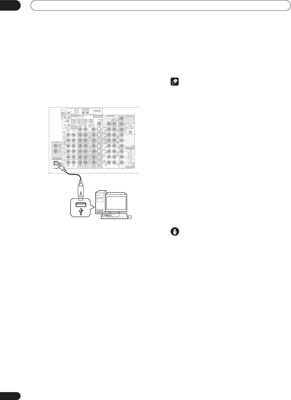
Other connections
10
72
En
Using the USB interface
It is possible to listen to two channels of audio from your
computer by connecting to the USB interface on the rear
of this receiver. Depending on your model of computer
and the software installed, you can listen to the stereo
audio source through the speaker setup you’ve
connected to this receiver.
1 Connect your computer’s USB terminal to the
USB terminal on the rear panel of this receiver.
2 Switch on your computer and this receiver.
If the computer was previously running, quit all
applications
3 If you’re connecting for the first time, wait for
the USB driver installation to finish.
The installation may take a minute or two to complete.
Make sure you leave the USB cable connected until the
dialog box indicates that the USB setup is finished. Note
that some older operating systems may require a disc for
installation.
• If your PC doesn’t recognize the receiver, try
disconnecting the USB cable and connecting it
again. If it is still unrecognized, restart the computer.
4Press INPUT on the remote control repeatedly to
select USB.
You can also use the
MULTI JOG
dial on the front panel
to select
USB
.
5 Make any necessary settings required to select
the USB interface as your computer audio output.
6 Turn up the volume control on your computer
and this receiver.
We recommend turning the computer volume to the
maximum level and using the volume control on this
receiver.
•You may want to start with a fairly low volume on this
receiver and turn it up as necessary after you’ve
checked your levels.
7 Start playback of a source on your computer.
Note
• Windows
®
XP, Windows
®
2000, Windows
®
Millennium Edition and Windows
®
98 operating
systems have been tested for compatibility with this
interface, but depending on your computer setup,
you may find that your system is not compatible.
• Make sure you use a USB cable that connects from
an A-type connector (from your PC) to a 4-pin B-type
connector (to the receiver).
• Any computer alert sounds will also be heard
through the speakers unless you switch them off
from the computer’s control panel.
• You won’t be able to hear the audio from the USB
connection through the digital outputs of this
receiver.
• Note that using hubs or extensions may cause
connection problems.
• The sound may be interrupted, degraded, or played
back incorrectly due to your software, PC settings or
PC specifications. Consult your PC manual regarding
USB devices.
Caution
• Make sure you don’t switch off the computer or
unplug the USB cable during playback.
• To prevent noise being output, don’t use other
software on your computer during playback.
• Pioneer is not responsible for computer system
damage, software crashes or failures, or any other
possible computer problems due to this
configuration.
Microsoft Windows
®
XP, Windows
®
2000, Windows
®
Millennium Edition, Windows
®
NT and Windows
®
98 are
registered trademarks of Microsoft Corporation, Inc.
CENTER
A-type USB
connector
B-type USB
connector
Personal computer
VSX-9300.book 72 ページ 2004年5月21日 金曜日 午前11時28分
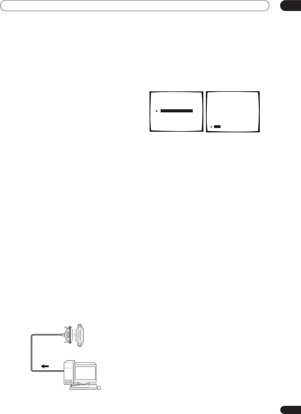
Other connections 10
73
En
Connecting a PC for Advanced
MCACC output
If you use the Professional Acoustic Calibration (see
page 84) to measure the reverb characteristics of your
listening room, you can check the results graphically
using a computer connected to this receiver. Use a
commercially-available RS-232C cable to connect the RS-
232C jack on your computer to the 9-pin RS-232C jack on
the back panel of this receiver (the cable must be cross
type, female–female).
To obtain the software to output the results, please
register this unit online as instructed on the front cover
of the manual. After registering, you will receive an email
within a week, in which both the software and instruction
manual will be available. If you have any questions
regarding, please contact the Customer Support Division
of Pioneer.
Please make sure your system meets the following
requirements:
•Operating system must be Windows
®
XP, Windows
®
2000, Windows
®
Millennium Edition, Windows
®
98
Second Edition, or Windows
®
NT 4.0 (Service pack 6).
•CPU must be at least Pentium 3 / 300MHz or AMD K6
/ 300MHz (or equivalent) with at least 128MB of
memory, and your monitor must be able to display a
minimum resolution of 800x600.
• An RS-232C port connector is necessary for
graphical output. Refer to the operating instructions
and/or the PC manufacturer for more information on
making the proper port settings.
• System must have internet access.
• Connect your computer to the RS-232C jack on
the rear panel of the receiver.
Make sure that the receiver and all connected
components are switched off and disconnected from the
power outlet when you do this.
Use a commercially-available cable to connect the RS-
232C jack on your computer to the 9-pin RS-232C jack on
this receiver. See the documentation provided with the
Advanced MCACC application for more information.
Advanced MCACC output using your PC
Before continuing, make sure you have completed
Professional Acoustic Calibration
on page 84.
1 Select ‘PC Output’ and press ENTER.
When the receiver is ready for transmission,
Operate a
PC
shows on the OSD.
2 Start the MCACC application on your computer.
Follow the instructions provided with the application. It
will take about ten seconds for the transmission to
complete, then you will be able to analyze the output on
your computer. Since the data will be cleared from the
receiver when you restart reverb measurement, you
might want to save the information on your PC after
measurement.
3 When you’re finished, select ‘Exit’ on the on-
screen display.
You’ll be taken to the Advanced EQ Setup. Depending on
the results, you may want to continue with the Advanced
EQ setup (see
Using Professional Acoustic Calibration
on
page 85 for more on this). You can also simply press
Exit
again to exit the Professional Acoustic Calibration setup.
RS-232C
PC
[ Auto Pro. ]
[ Reverb Measurement ]
[ Reverb View ]
[ PC Output ]
[ Advanced EQ Setup ]
[
Exit
]
Acoustic Cal EQ Pro.
Acoustic Cal EQ Pro.
PC Output
Operate a PC.
[ Exit ]
VSX-9300.book 73 ページ 2004年5月21日 金曜日 午前11時28分
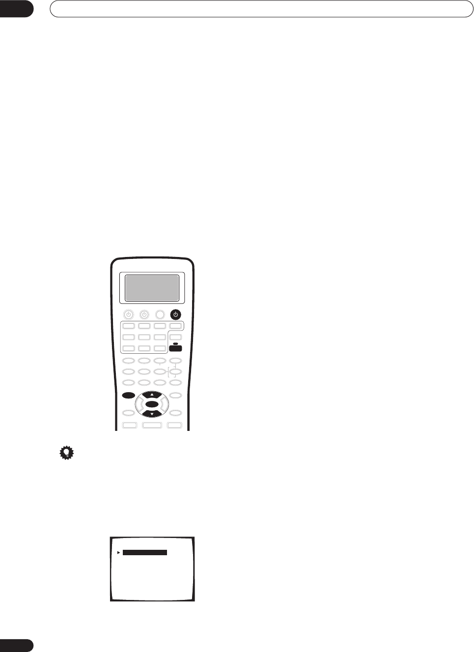
Advanced setup
11
74
En
Chapter 11
Advanced setup
The System Setup menu
The System Setup menu is where you can make
customized settings to reflect how you are using the
receiver.
1 Switch on the receiver and your TV.
2 Using the remote control, press RECEIVER, then
press the SYSTEM SETUP button.
An on-screen display (OSD) appears on your TV. Use the
/
(cursor up/down) buttons and
ENTER
on the remote
control to navigate through the screens and select menu
items.
Tip
• You can also use the front panel display to make
settings. You can also use the
MULTI JOG
dial and
ENTER
on the front panel instead of the
/
(cursor
up/down) buttons and
ENTER
on the remote control.
3Select the setting you want to adjust then press
ENTER.
•
Surround Setup
– Access the setup menu for basic
surround sound settings (see
Making receiver
settings from the Surround Setup menu
on page 50
for more on this).
•
THX CINEMA Setup
– Select the decoding method
used with the
THX CINEMA
mode (see
THX CINEMA
Setup
below).
•
Input Assign
– Specify what you’ve connected to the
digital and component video inputs (see
The Input
Assign menu
below).
•
Function Rename
– Change the names that appear
on the receiver display and on-screen display (see
Function Rename
on page 76).
•
PHONO/LINE Setup
– Specify how you’re using the
PHONO
jack on the rear of the receiver (see
PHONO/
LINE Setup
on page 77).
•
Multi Room
– Specify your volume setting for a
multi-room setup and your IR receiver type (see
Multi-
Room and IR receiver setup
on page 78).
•
12V Trigger
– Specify which components are
switched on or off using the 12 volt trigger (see
12 Volt
Trigger
on page 78).
4 Make the adjustments necessary for each
setting, pressing ENTER to confirm after each
setting.
SYSTEM SETUP
ENTER
RECEIVER
RECEIVER
System Setup
[ 1. Surround Setup ]
[ 2. THX CINEMA Setup ]
[ 3. Input Assign ]
[ 4. Function Rename ]
[ 5. PHONO/LINE Setup ]
[ 6. Multi Room ]
[ 7. 12V Trigger ]
[ Exit ]
VSX-9300.book 74 ページ 2004年5月21日 金曜日 午前11時28分
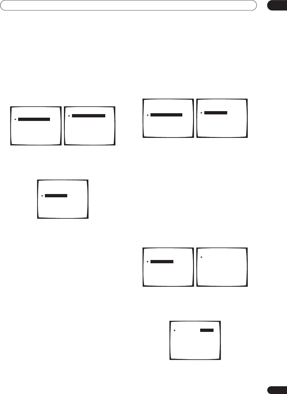
Advanced setup 11
75
En
THX CINEMA Setup
• Default setting:
PLII / PLIIx MOVIE
If you want, you can choose which decoding method the
receiver will use for 2-channel sources when you’ve
selected the
THX CINEMA
mode (see
Listening in
surround sound
on page 37 for details).
1 Select ‘THX CINEMA Setup’ from the System
Setup menu.
The current setting is highlighted on-screen:
2 Select the THX CINEMA decoding format you
want.
For more on decoding formats see
Surround sound
formats
on page 95.
•
2
Pro Logic II /
2
Pro Logic IIx MOVIE
•
2
Pro Logic
•
Neo:6 CINEMA
3 When you're finished, select ‘Exit’.
You will return to the System Setup menu.
The Input Assign menu
You only need to make settings in the Input Assign menu
if you didn’t hook up your digital equipment according to
the default settings for the digital inputs, or if you have
connected equipment using component video cables.
• Select ‘Input Assign’ from the System Setup
menu.
The Input Assign menu appears on screen:
Assigning the digital inputs
• Default settings:
Digital-1
(optical) –
TV/SAT
Digital-2
(optical) –
CD-R
Digital-3
(coaxial) –
DVD/LD
Digital-4
(coaxial) –
CD
You only need to do this if you didn’t hook up your digital
equipment according to the default settings for the
digital inputs (see above). This setting tells the receiver
what digital equipment is hooked up to which terminal so
the buttons on the remote correspond to what you have
hooked up.
1 Select ‘Digital-In Select’ from the Input Assign
menu.
2 Select the number of the digital input to which
you’ve connected your digital component.
The numbers correspond with the numbers beside the
inputs on the back of the receiver.
System Setup
[ 1. Surround Setup ]
[ 2. THX CINEMA Setup ]
[ 3. Input Assign ]
[ 4. Function Rename ]
[ 5. PHONO/LINE Setup ]
[ 6. Multi Room ]
[ 7. 12V Trigger ]
[ Exit ]
2. THX CINEMA Setup
[ PL I I / PL I Ix MOVIE ]
[ PRO LOGIC ]
[ NEO:6 CINEMA ]
[ Exit ]
2. THX CINEMA Setup
[ PL I I / PL I Ix MOVIE ]
[ PRO LOGIC ]
[ NEO:6 CINEMA ]
[ Exit ]
System Setup
[ 1. Surround Setup ]
[ 2. THX CINEMA Setup ]
[ 3. Input Assign ]
[ 4. Function Rename ]
[ 5. PHONO/LINE Setup ]
[ 6. Multi Room ]
[ 7. 12V Trigger ]
[ Exit ]
3. Input Assign
[Digital-In Select ]
[Component-In Select ]
[Exit
]
3. Input Assign
[Digital-In Select ]
[Component-In Select ]
[Exit
]
Digital - In Select
Digital - 1 [ TV/SAT ]
Digital - 2 [ CD-R ]
Digital - 3 [ DVD/LD ]
Digital - 4 [ CD ]
[ Exit ]
Digital - In Select
Digital - 1 [ DVD/LD ]
Digital - 2 [ CD-R ]
Digital - 3 [ OFF ]
Digital - 4 [ CD ]
[ Exit ]
VSX-9300.book 75 ページ 2004年5月21日 金曜日 午前11時28分
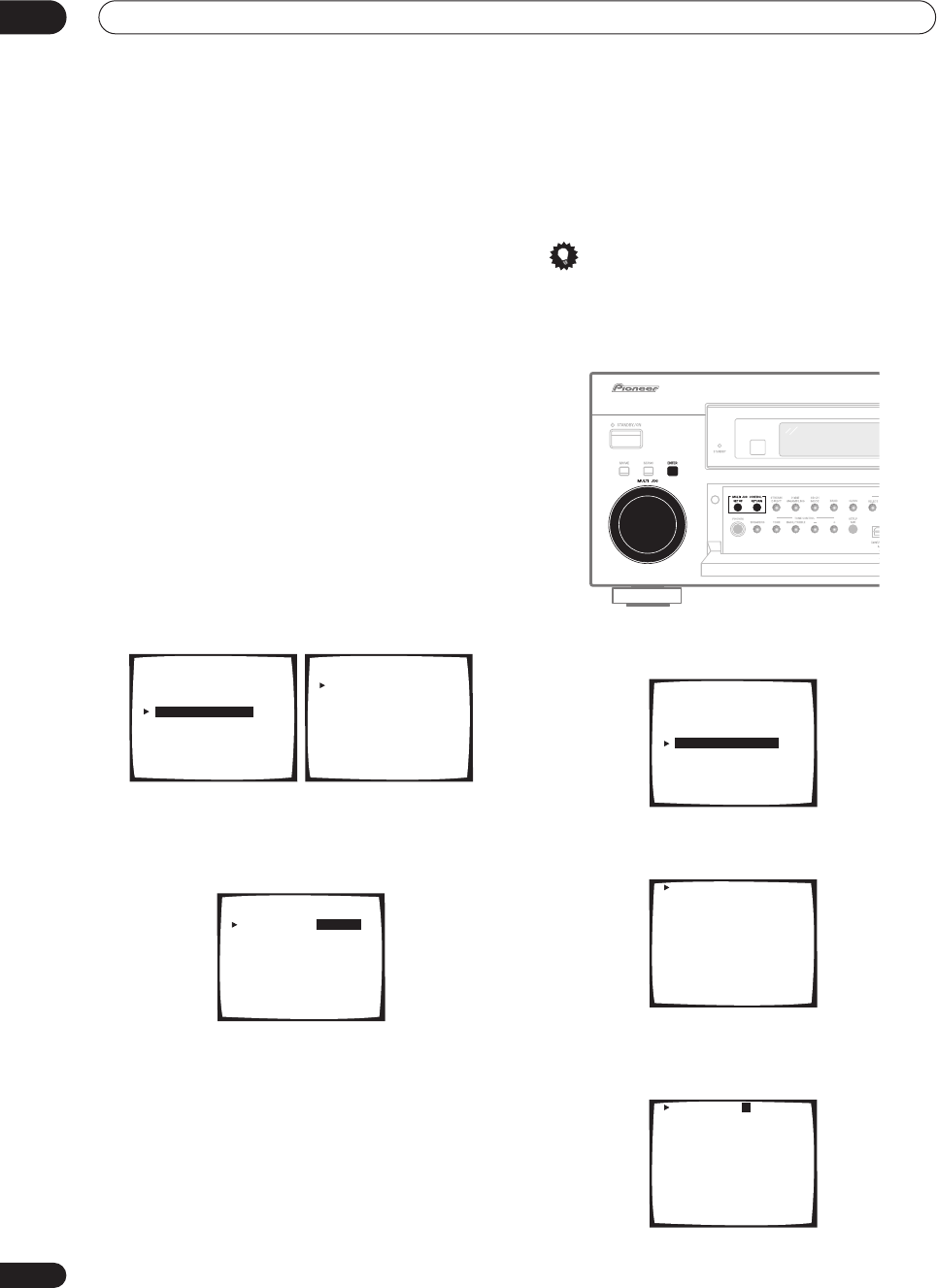
Advanced setup
11
76
En
3Select the component that corresponds with the
one you connected to that input
Select between
DVD/LD
,
TV/SAT
,
VCR1
,
VCR 2
,
CD
,
CD-R
or
MD
.
•Use the
/
(cursor up/down)
buttons and
ENTER
to
do this.
• If you assign a digital input to a certain function (for
example,
DVD/LD
) then any digital inputs previously
assigned to that function will automatically be
switched off.
4 When you're finished, select ‘Exit’.
You will return to the Input Assign menu.
Assigning the component video inputs
• Default settings:
Component-1
–
OFF
Component-2
–
OFF
If you used component video cables to connect your
video equipment you must tell the receiver which device
it is, or else you may see the S-video or composite video
input instead of the component video signal.
1 Select ‘Component-In Select’ from the Input
Assign menu.
2Select the number of the component video input
to which you’ve connected your video component.
The numbers correspond with the numbers beside the
inputs on the back of the receiver.
3Select the component that corresponds with the
one you connected to that input.
•Use the
/
(cursor up/down)
buttons and
ENTER
to
do this.
•If you connect any source component to the receiver
using a component video input, you should also have
your TV connected to this receiver's component video
MONITOR
output.
4 When you're finished, select ‘Exit’.
You will return to the Input Assign menu.
Function Rename
You can customize the names that appears on the
display when you select an input source (for example,
you could change the name of
VCR1/DVR
to
DVR-310
).
Tip
• It’s convenient to use the front panel controls when
editing names. However, if you want to use the
remote, you can press and hold
/
to change
characters quickly.
1Select ‘Function Rename’ from the System Setup
menu.
2 Select the name of the input you want to
rename.
3 Edit the name as necessary, then press ENTER
repeatedly to set the name and move to the
following line.
3. Input Assign
[Digital-In Select ]
[Component-In Select ]
[Exit
]
Component - In Select
Component - 1 [ OFF ]
Component - 2 [ OFF ]
[ Exit ]
Component - In Select
Component - 1 [ DVD/LD ]
Component - 2 [ OFF ]
[ Exit ]
System Setup
[ 1. Surround Setup ]
[ 2. THX CINEMA Setup ]
[ 3. Input Assign ]
[ 4. Function Rename ]
[ 5. PHONO/LINE Setup ]
[ 6. Multi Room ]
[ 7. 12V Trigger ]
[ Exit ]
DVD/LD [ DVD/LD ]
TV/SAT [ TV/SAT ]
VCR1/DVR [ VCR1/DVR ]
VCR2 [ VCR2 ]
VIDEO [ VIDEO ]
PHONO/LINE [ PHONO ]
CD [ CD ]
CD-R/TAPE1 [ CD-R/TAPE1 ]
MD/TAPE2 [ MD/TAPE2 ]
USB [ USB ]
[ Exit ]
DVD/LD [ DVD/LD ]
TV/SAT [ TV/SAT ]
VCR1/DVR [ VCR1/DVR ]
VCR2 [ VCR2 ]
VIDEO [ VIDEO ]
PHONO/LINE [ PHONO ]
CD [ CD ]
CD-R/TAPE1 [ CD-R/TAPE1 ]
MD/TAPE2 [ MD/TAPE2 ]
USB [ USB ]
[ Exit ]
VSX-9300.book 76 ページ 2004年5月21日 金曜日 午前11時28分
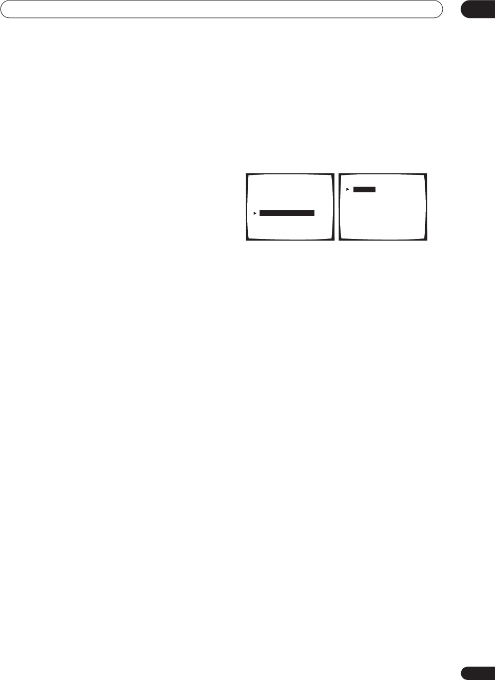
Advanced setup 11
77
En
Use the front panel
MULTI JOG
dial (or
/
on the
remote) to change the character and
ENTER
to move
forward a position. If you want to change a character you
input, you can press
RETURN
to go back one position.
The name can be up to ten characters (the possible
characters are listed below).
ABCDEFGHIJKLMNOPQRSTUVWXYZ
abcdefghijklmnopqrstuvwxyz
0123456789
!”#$%&’()*+,–./:;<=>?@[ \ ]^_{|} (space)
4Select another name to edit, or select ‘Exit’ from
the bottom of the list if you’re done.
If you’ve selected another name, repeat step 3, otherwise
you’ll return to the System Setup menu.
PHONO/LINE Setup
• Default setting:
PHONO
You can choose whether you want to use the
PHONO
jack on the rear of the receiver to connect a turntable, or
a line level component (such as a CD or DVD player).
1 Select ‘PHONO/LINE Setup’ from the System
Setup menu.
The current setting is highlighted in the display.
2 Select either PHONO or LINE.
•
PHONO
– High level setting for turntables (without a
built-in equalizer or pre-amplifier)
•
LINE
– Line level setting for all audio components
other than a turntable (except those with a built-in
phono equalizer
3 When you’re finished, select ‘Exit’.
You will return to the System Setup menu.
System Setup
[ 1. Surround Setup ]
[ 2. THX CINEMA Setup ]
[ 3. Input Assign ]
[ 4. Function Rename ]
[ 5. PHONO/LINE Setup ]
[ 6. Multi Room ]
[ 7. 12V Trigger ]
[ Exit ]
5. PHONO / LINE Setup
[ PHONO ]
[ LINE ]
[ Exit ]
VSX-9300.book 77 ページ 2004年5月21日 金曜日 午前11時28分
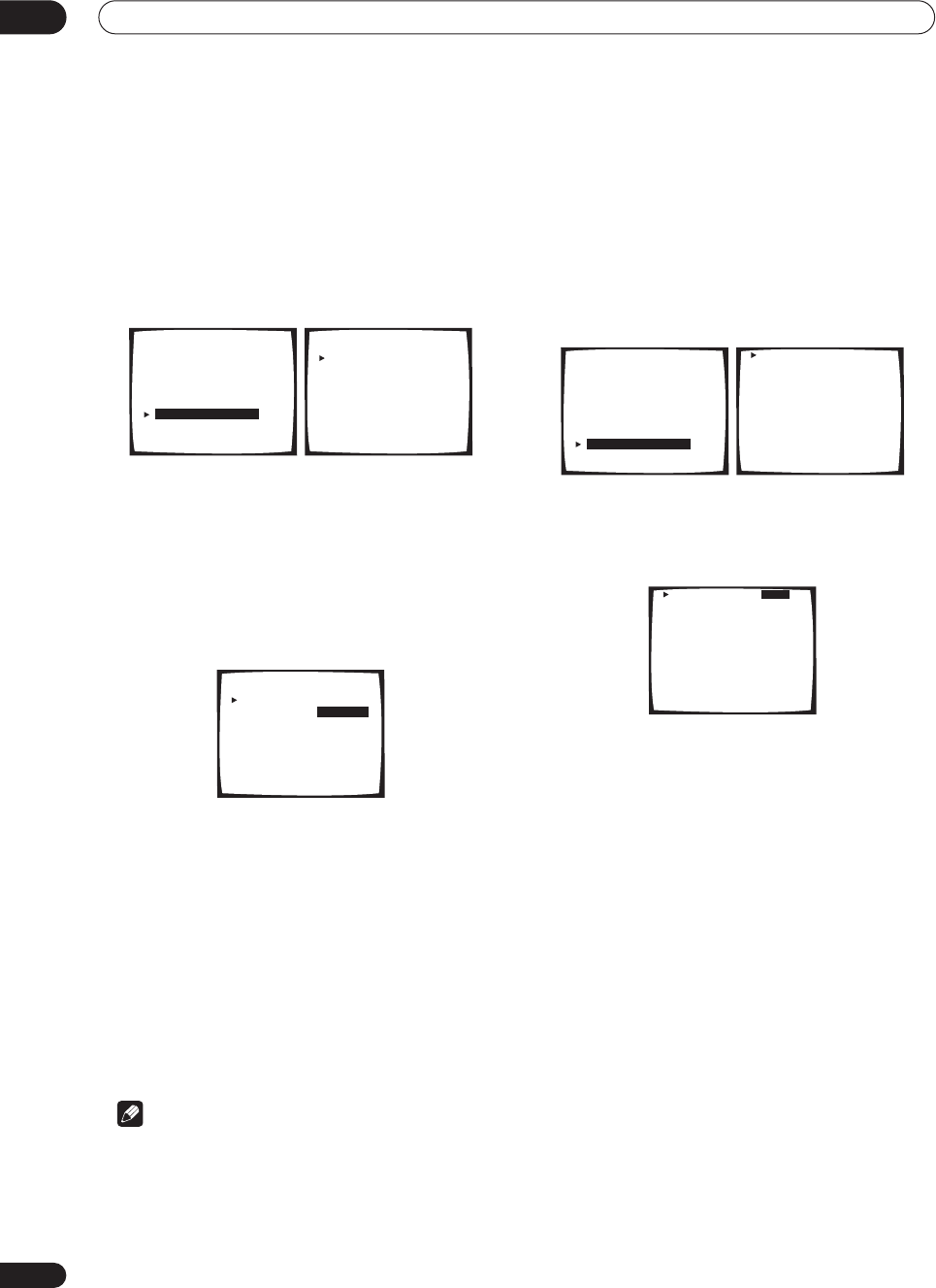
Advanced setup
11
78
En
Multi-Room and IR receiver setup
• Default setting:
VARIABLE
/
Setting 1
If you’ve made multi-room connections (see
Multi-room
listening
on page 69) you may need to specify your
volume setting. Also use this menu to specify your IR
receiver type (if necessary).
1 Select ‘Multi-Room’ from the System Setup
menu.
2 Select the volume level setting.
•
VARIABLE
– Use this setting if you’ve connected a
power amplifier in the sub room (this receiver is
simply being used as a pre-amp) and you will be
using this receiver’s controls to adjust the volume.
•
FIXED
– Use this setting if you’ve connected a fully
integrated amplifier (such as another Pioneer VSX
receiver) in the sub room and want to use that
receiver’s volume controls.
With the
FIXED
setting, the source is sent from this
receiver at maximum volume, so make sure the volume is
quite low in the sub room at first and then experiment to
find the correct level.
3 Select the type of IR receiver you’re using.
•
Setting 1
– Use this setting for all (other) IR
receivers.
•
Setting 2
– Use this setting if the IR receiver you’re
using doesn’t seem to work after selecting
Setting 1
.
4 When you're finished, select ‘Exit’ and press
ENTER.
You will return to the System Setup menu.
Note
• Some IR receivers may not work with this receiver.
Check with your audio dealer for more information.
• If you selected
MR&S
in the
Surround back speaker
setting
on page 51, you won’t be able to change the
volume level.
12 Volt Trigger
• Default setting:
OFF
(all components)
After connecting a component the 12 volt trigger (see
Switching components on and off using the 12 volt trigger
on page 61), it switches on automatically when you select
an input function set to switch the trigger on. Specify
which input functions switch on the trigger below.
1 Select ‘12V Trigger’ from the System Setup
menu.
2 Select an input function and choose the setting
that you want.
This should be the input function, that when selected,
switches on the 12 volt trigger.
•
OFF
– 12 volt trigger is not activated for the selected
component.
•
ON
– 12 volt trigger is activated for the selected
component.
3Repeat for as many input functions as you would
like to set.
4 When you're finished, select ‘Exit’.
You will return to the System Setup menu.
System Setup
[ 1. Surround Setup ]
[ 2. THX CINEMA Setup ]
[ 3. Input Assign ]
[ 4. Function Rename ]
[ 5. PHONO/LINE Setup ]
[ 6. Multi Room ]
[ 7. 12V Trigger ]
[ Exit ]
6. Multi Room
Volume Level
[ VARIABLE ]
IR Receiver
[ Setting 1 ]
[ Exit ]
CAUTION: If the "FIXED"
position is chosen, the
volume will be loud.
6. Multi Room
Volume Level
[ VARIABLE ]
IR Receiver
[ Setting 1 ]
[ Exit ]
CAUTION: If the "FIXED"
position is chosen, the
volume will be loud.
System Setup
[ 1. Surround Setup ]
[ 2. THX CINEMA Setup ]
[ 3. Input Assign ]
[ 4. Function Rename ]
[ 5. PHONO/LINE Setup ]
[ 6. Multi Room ]
[ 7. 12V Trigger ]
[ Exit ]
DVD/LD [ OFF ]
TV/SAT [ OFF ]
VCR1/DVR [ OFF ]
VCR2 [ OFF ]
VIDEO [ OFF ]
PHONO/LINE [ OFF ]
CD [ OFF ]
CD-R/TAPE1 [ OFF ]
MD/TAPE2 [ OFF ]
USB [ OFF ]
TUNER [ OFF ]
[ Exit ]
DVD/LD [ ON ]
TV/SAT [ OFF ]
VCR1/DVR [ OFF ]
VCR2 [ OFF ]
VIDEO [ OFF ]
PHONO/LINE [ OFF ]
CD [ OFF ]
CD-R/TAPE1 [ OFF ]
MD/TAPE2 [ OFF ]
USB [ OFF ]
TUNER [ OFF ]
[ Exit ]
VSX-9300.book 78 ページ 2004年5月21日 金曜日 午前11時28分
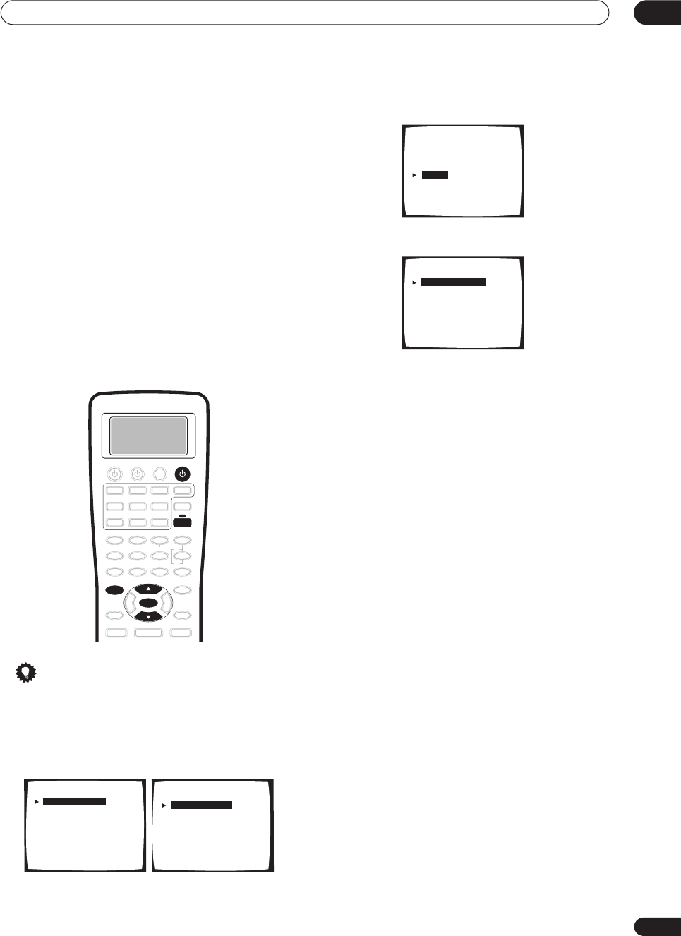
Advanced setup 11
79
En
The Expert setup menu
The settings in the Expert setup menu are more
advanced features of this receiver that you can use to
make detailed adjustments when you’re more familiar
with the system. Before making these settings, you
should have already completed
Automatically setting up
for surround sound
on page 12.
You only need to make these settings once (unless you
change the placement of your current speaker system or
add new speakers).
1 Make sure your receiver and TV are both
switched on.
2 Using the remote control, press RECEIVER, then
press the SYSTEM SETUP button.
An on-screen display (OSD) appears on your TV. Use the
/
(cursor up/down) buttons and
ENTER
on the remote
control to navigate through the screens and select menu
items.
Tip
• You can also use the front panel display to make
settings. You can also use the
MULTI JOG
dial and
ENTER
on the front panel instead of the
/
(cursor
up/down) buttons and
ENTER
on the remote control.
3 Select ‘Surround Setup’ then press ENTER.
4 Select ‘Expert’ then press ENTER.
5 Select the setting you want to adjust.
•
Crossover Network
– Specify which frequencies will
be sent to the subwoofer (see
Crossover Network
below).
•
Fine Channel Level
– Make fine adjustments to the
overall balance of your speaker system (see
Fine
Channel Level
below).
•
Fine Channel Delay
– Make precise delay settings for
your speaker system (see
Fine Channel Delay
on
page 81).
•
Acoustic Cal EQ
– Measure the acoustic
characteristics of your room and make detailed
adjustments to the frequency balance of your
speaker system (see
Acoustic Calibration EQ
on
page 81 and
Professional Acoustic Calibration
on
page 84).
•
Bass Peak Level
– Prevent bass tones from distorting
the sound from your speakers (see
Bass Peak Level
on
page 86).
•
D-Range Control
– Specify the amount of dynamic
range adjustment to Dolby Digital and DTS movie
soundtracks (see
Dynamic Range Control
on
page 87).
6 Make the adjustments necessary for each
setting, pressing ENTER to confirm after each
setting.
When you’re finished, you can select
Exit
, then press
ENTER
to go back to the System Setup menu.
SYSTEM SETUP
ENTER
RECEIVER
RECEIVER
System Setup
[ 1. Surround Setup ]
[ 2. THX CINEMA Setup ]
[ 3. Input Assign ]
[ 4. Function Rename ]
[ 5. PHONO/LINE Setup ]
[ 6. Multi Room ]
[ 7. 12V Trigger ]
[ Exit ]
1.Surround Setup
[ SurrBack System ]
[ Auto Setting ]
[ Normal ]
[ Expert ]
[ Exit ]
1.Surround Setup
[ SurrBack System ]
[ Auto Setting ]
[ Normal ]
[ Expert ]
[ Exit
]
Expert
[ Crossover Network ]
[ Fine Channel Level ]
[ Fine Channel Delay ]
[ Acoustic Cal EQ ]
[ Bass Peak Level ]
[ D-Range Control ]
[ Exit ]
VSX-9300.book 79 ページ 2004年5月21日 金曜日 午前11時28分
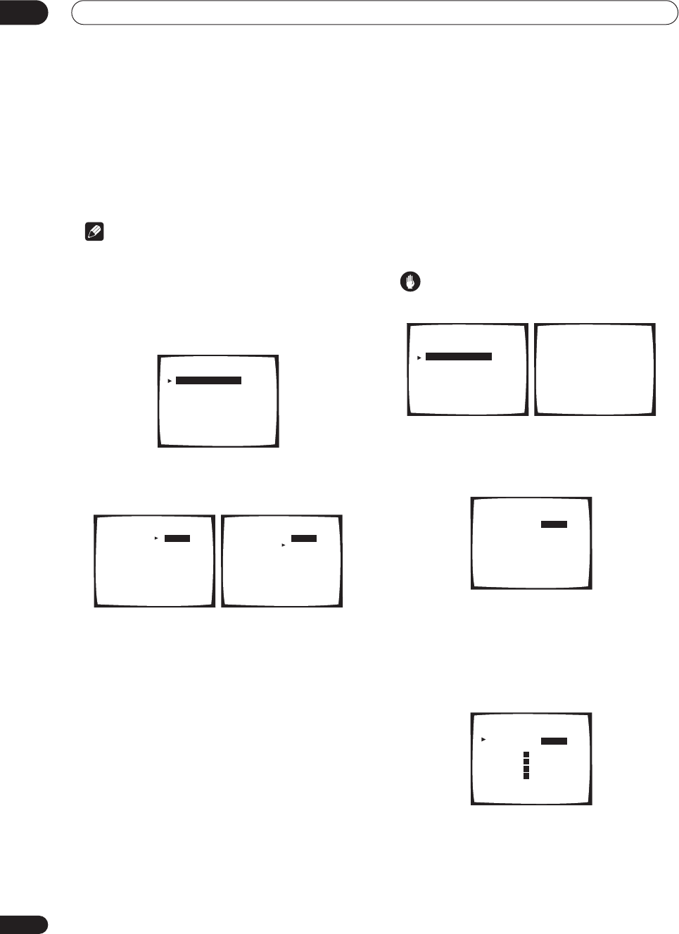
Advanced setup
11
80
En
Crossover Network
• Default setting:
80Hz
This setting decides the cutoff between bass sounds
playing back from the speakers selected as
LARGE
, or
the subwoofer, and bass sounds playing back from those
selected as
SMALL
. It also decides where the cutoff will
be for bass sounds in the LFE channel.
Note
•For more on selecting the speaker sizes, see
Normal
surround setting
on page 51.
• You don’t need to set the crossover frequency if all
speakers are set to
LARGE
.
1 Select ‘Crossover Network’ from the Expert
setup menu.
2 Choose the frequency cutoff point.
Frequencies below the cutoff point will be sent to the
subwoofer (or
LARGE
speakers).
3 When you're finished, select ‘Exit’.
You will return to the Expert setup menu.
Fine Channel Level
• Default setting:
0dB
(all channels)
You can achieve better surround sound by properly
adjusting the overall balance of your speaker system. The
following setting can help you make detailed
adjustments that you may not achieve using the
Normal
surround setting
on page 51.
1Select ‘Fine Channel Level’ from the Expert setup
menu.
The volume increases to the
0dB
reference level.
Caution
• After pressing
ENTER
, loud test tones will be output.
2 Adjust the level of the left channel.
This will be the reference speaker level, so you may want
to keep the level around
0dB
so that you’ll have plenty of
room to adjust the other speaker levels.
3Select each channel in turn and adjust the levels
(
+/– 10dB
)
as necessary.
Use
/
(cursor up/down) to adjust the volume of the
speaker you selected to match the front left (reference)
speaker. When it sounds like both tones are the same
volume, press
ENTER
to confirm and continue to the next
channel.
• If you want to go back and adjust a channel, simply
use
/
(cursor up/down) to select it.
4 When you're finished, select ‘Exit’.
You will return to the Expert setup menu.
Expert
[ Crossover Network ]
[ Fine Channel Level ]
[ Fine Channel Delay ]
[ Acoustic Cal EQ ]
[ Bass Peak Level ]
[ D-Range Control ]
[ Exit ]
50Hz
80Hz
100Hz
150Hz
200Hz
Exit
Crossover Network
Frequency [ ]
[ ]
[ ]
[ ]
[ ]
[ ]
(THX Speaker = 80Hz)
50Hz
80Hz
100Hz
150Hz
200Hz
Exit
Crossover Network
Frequency [ ]
[ ]
[ ]
[ ]
[ ]
[ ]
(THX Speaker = 80Hz)
Expert
[ Crossover Network ]
[ Fine Channel Level ]
[ Fine Channel Delay ]
[ Acoustic Cal EQ ]
[ Bass Peak Level ]
[ D-Range Control ]
[ Exit ]
Please Wait
Caution!!
Test tone is
output loudly.
Fine Channel Level
+10. 0
dB
Left [ ]
Fine Channel Level
+10. 0
dB
+10. 0
dB
+10. 0
dB
+10. 0
dB
+10. 0
dB
+10. 0
dB
+10. 0
dB
Right [ ]
Center [ ]
Surround [ ]
Surround [ ]
SurrBack [ ]
SurrBack [ ]
Subwoofer [ ]
[
Exit
]
Fine Channel Level
STD:Left +10. 0
dB
R
R
L
L
VSX-9300.book 80 ページ 2004年5月21日 金曜日 午前11時28分
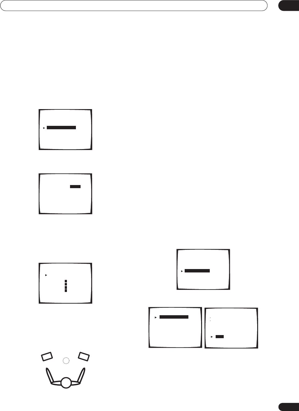
Advanced setup 11
81
En
Fine Channel Delay
For proper sound depth and separation with your system,
it is necessary to add a slight bit of delay to some
speakers so that all sounds will arrive at the listening
position at the same time. The following setting can help
you make detailed adjustments that you may not achieve
using the
Normal surround setting
on page 51.
1Select ‘Fine Channel Delay’ from the Expert setup
menu.
2 Adjust the distance of the left channel from the
listening position.
3 Select each channel in turn and adjust the
distance as necessary.
Use
/
(cursor up/down) to adjust the delay of the
speaker you selected to match the front left (reference)
speaker. The delay is measured in terms of speaker
distance from
0.5
to
45
feet.
Listen to the reference speaker and use it to measure the
target channel. Face the two speakers with your arms
outstretched pointing at each speaker. Try to make the
two tones sound as if they are arriving simultaneously at
a position slightly in front of you and between your arm
span.
When it sounds like the delay settings are matched up,
press
ENTER
to confirm and continue to the next
channel.
• If you want to go back and adjust a channel, simply
use
/
(cursor up/down) to select it.
4 When you're finished, select ‘Exit’.
You will return to the Expert setup menu.
Acoustic Calibration EQ
Acoustic Calibration Equalization is a kind of room
equalizer for your speakers (excluding the subwoofer). It
works by measuring the acoustic characteristics of your
room and neutralizing the ambient characteristics that
can color the original source material. You can also make
these settings manually to get a frequency balance that
suits your tastes. A more advanced setup is also
available, where you can make detailed settings
according to your room’s reverb characteristics (see
Professional Acoustic Calibration
on page 84). You should
have the mic connected when using any of the setup
options.
Setting the Acoustic Calibration EQ automatically
If you have already completed
Automatically setting up for
surround sound
on page 12,
ALL CH ADJUST
and
FRONT
ALIGN
(below) should already be set. Therefore, if you
want to adjust your settings manually, you can skip to
Setting the Acoustic Calibration EQ manually
below.
1 Select ‘Acoustic Cal EQ’ from the Expert setup
menu.
2 Select ‘EQ AUTO SETTING’ then select ‘Start’.
As the receiver outputs test tones, the frequency balance
is adjusted automatically for the following settings:
•
ALL CH ADJUST
– All the speakers are set
individually so no special weighting is given to any
one channel.
•
FRONT ALIGN
– All speakers are set in accordance
with the front speaker settings.
Expert
[ Crossover Network ]
[ Fine Channel Level ]
[ Fine Channel Delay ]
[ Acoustic Cal EQ ]
[ Bass Peak Level ]
[ D-Range Control ]
[ Exit ]
10.0ft
Fine Channel Delay
Left [ ]
Fine Channel Delay
STD:Left 25.0ft
Right [ ]
Center [ ]
Surround [ ]
Surround [ ]
SurrBack [ ]
SurrBack [ ]
Subwoofer [ ]
[
Exit
]
R
R
L
L
10.0ft
10.0ft
10.0ft
10.0ft
10.0ft
10.0ft
10.0ft
Expert
[ Crossover Network ]
[ Fine Channel Level ]
[ Fine Channel Delay ]
[ Acoustic Cal EQ ]
[ Bass Peak Level ]
[ D-Range Control ]
[ Exit ]
[ EQ AUTO SETTING ]
[ CUSTOM1 ADJUST ]
[ CUSTOM2 ADJUST ]
[ DATA COPY ]
[ DATA CHECK ]
[ Professional ]
[
Exit
]
Acoustic Cal EQ EQ AUTO SETTING
Set microphone
Turn on subwoofer
[ Start ]
[ Cancel ]
VSX-9300.book 81 ページ 2004年5月21日 金曜日 午前11時28分
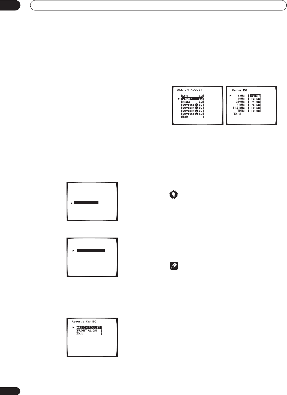
Advanced setup
11
82
En
!! Complete !!
is displayed on-screen after the Acoustic
Calibration Equalization is set. If you want to check the
settings, select
Check
. Select
Next
after you have
finished checking each screen.
• If you want to copy these settings and adjust them
manually, select
Data Copy
. Go to step 3 of
Copying
your Acoustic Calibration EQ settings
below.
3 When you're finished, select ‘Exit’.
You will return to the Acoustic Cal EQ setup menu.
Setting the Acoustic Calibration EQ manually
Before manually adjusting the Acoustic Calibration EQ,
we recommend copying the
ALL CH ADJUST
or the
FRONT ALIGN
settings from the auto setup above (or
from
Automatically setting up for surround sound
on
page 12) to one of the custom settings. Instead of just a
flat EQ curve, this will give you a reference point from
which to start (see
Copying your Acoustic Calibration EQ
settings
below for how to do this).
1 Select ‘Acoustic Cal EQ’ from the Expert setup
menu.
2 Select CUSTOM1 ADJUST or CUSTOM2 ADJUST.
3 Select which method you would like to use to
adjust the overall frequency balance.
It is best to choose whichever one you copied to the
custom setting in
Copying your Acoustic Calibration EQ
settings
below.
•
ALL CH ADJUST
– All the speakers can be set
independently so no special weighting is given to any
one channel. When adjusting, test tones will sound
for each individual channel.
•
FRONT ALIGN
– Speakers are set in accordance with
the front speaker settings. The sound of the test tone
will alternate between the left front (reference)
speaker and the target speaker.
4 Select the channel(s) you want and adjust to
your liking.
Use the
/
(cursor up/down) buttons to select the
channel (and
ENTER
to select it).
Use the
/
(cursor up/down) buttons to select the
frequency and
/
(cursor up/down) to boost or cut the
EQ. When you’re finished, the cursor automatically
moves to the next channel after you press
ENTER
.
• The front speakers can’t be adjusted if you selected
FRONT ALIGN
.
Tip
• Changing the frequency curve of one channel too
drastically will affect the overall balance. If the
speaker balance seems uneven, you can raise or
lower channel levels using test tones with the
TRIM
feature. Use
/
(cursor up/down) to raise or lower
the channel level for the current speaker.
5 When you're finished, select ‘Exit’.
Select
Exit
again to confirm your custom settings and
return to the Acoustic Cal EQ setup menu.
Note
• Note that five bands are available for adjustment
here, however six bands are measured and displayed
with the
Professional Acoustic Calibration
on
page 84(including the PC graphical output feature).
The 1kHz band acts as a reference setting (to ensure
optimal adjustment of the other frequency settings)
for a total of six band adjustment.
Expert
[ Crossover Network ]
[ Fine Channel Level ]
[ Fine Channel Delay ]
[ Acoustic Cal EQ ]
[ Bass Peak Level ]
[ D-Range Control ]
[ Exit ]
[ EQ AUTO SETTING ]
[ CUSTOM1 ADJUST ]
[ CUSTOM2 ADJUST ]
[ DATA COPY ]
[ DATA CHECK ]
[ Professional ]
[
Exit
]
Acoustic Cal EQ
VSX-9300.book 82 ページ 2004年5月21日 金曜日 午前11時28分
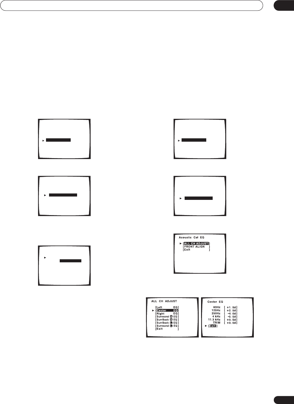
Advanced setup 11
83
En
Copying your Acoustic Calibration EQ settings
If you want to manually adjust the Acoustic Calibration
EQ (see
Setting the Acoustic Calibration EQ manually
above), we recommend copying the
ALL CH ADJUST
or
the
FRONT ALIGN
settings from the
Auto
setup above
(or from
Automatically setting up for surround sound
on
page 12) to one of the custom settings. Instead of just a
flat EQ curve, this will give you a reference point from
which to start.
1 Select ‘Acoustic Cal EQ’ from the Expert setup
menu.
2 Select ‘DATA COPY’ then press ENTER.
3 Select CUSTOM1 or CUSTOM2 then use the
/
(cursor up/down) buttons to select the setting you
want to copy.
• You can also copy from one custom setting to
another. For more on the
ALL CH ADJUST
and
FRONT ALIGN
settings, see
Setting the Acoustic
Calibration EQ automatically
above.
4 Select ‘Exit’ to copy and confirm.
You will return to the Acoustic Cal EQ setup menu.
Checking your Acoustic Calibration EQ settings
If you want to manually adjust the Acoustic Calibration
EQ (see
Setting the Acoustic Calibration EQ manually
above), we recommend copying the
ALL CH ADJUST
or
the
FRONT ALIGN
settings from the
Auto
setup above
(or from
Automatically setting up for surround sound
on
page 12) to one of the custom settings. Instead of just a
flat EQ curve, this will give you a reference point from
which to start.
1 Select ‘Acoustic Cal EQ’ from the Expert setup
menu.
2 Select ‘DATA CHECK’ then press ENTER.
3 Select the setting you want to check.
4 Select the channels you want, selecting ‘Exit’
when you’re finished checking each one.
5 When you're finished, select ‘Exit’.
You will return to the Acoustic Cal EQ setup menu.
Expert
[ Crossover Network ]
[ Fine Channel Level ]
[ Fine Channel Delay ]
[ Acoustic Cal EQ ]
[ Bass Peak Level ]
[ D-Range Control ]
[ Exit ]
[ EQ AUTO SETTING ]
[ CUSTOM1 ADJUST ]
[ CUSTOM2 ADJUST ]
[ DATA COPY ]
[ DATA CHECK ]
[ Professional ]
[
Exit
]
Acoustic Cal EQ
CUSTOM1
CUSTOM2
[ ]
EQ DATA COPY
ALL CH ADJUST
[ ]
NOT DATA COPY
[
Exit
]
Expert
[ Crossover Network ]
[ Fine Channel Level ]
[ Fine Channel Delay ]
[ Acoustic Cal EQ ]
[ Bass Peak Level ]
[ D-Range Control ]
[ Exit ]
[ EQ AUTO SETTING ]
[ CUSTOM1 ADJUST ]
[ CUSTOM2 ADJUST ]
[ DATA COPY ]
[ DATA CHECK ]
[ Professional ]
[
Exit
]
Acoustic Cal EQ
VSX-9300.book 83 ページ 2004年5月21日 金曜日 午前11時28分
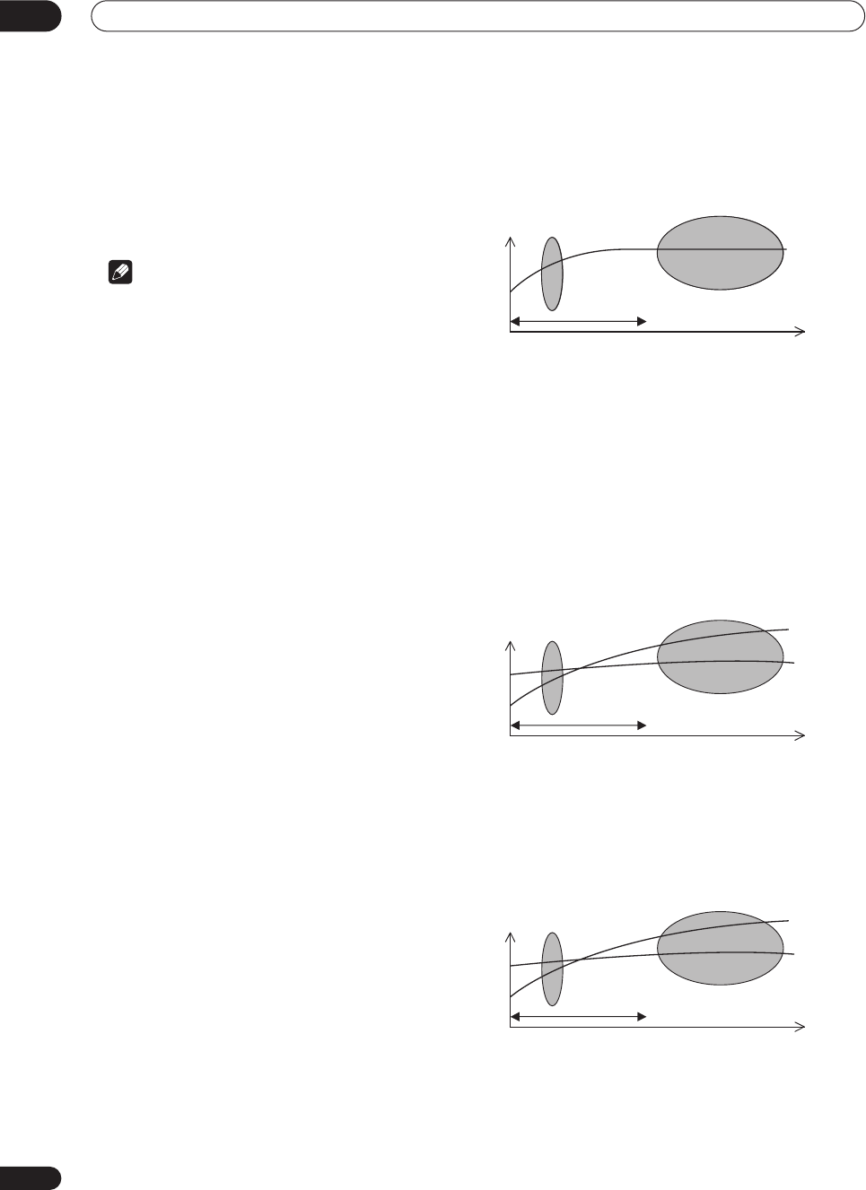
Advanced setup
11
84
En
Professional Acoustic Calibration
This setup minimizes the unwanted effects of room
reverberation by calibrating your system based on the
direct sound coming from the speakers. It can also
provide you with a graphical output of the frequency
response of your room.
Note
• Before setting up with Professional Acoustic
Calibration, you should finish calibrating using the
Auto Surround Setup on page 12.
How to use Professional Acoustic Calibration
If you find that lower frequencies seem overly reverberant
in your listening room (i.e. it sounds ‘boomy’), or that
different channels seem to exhibit different reverb
characteristics, use the Auto Pro setup to calibrate the
room automatically. This should provide a more balanced
calibration than simply using the standard Acoustic
Calibration EQ.
If you still aren’t satisfied with the results, the manual
Advanced EQ Setup allows you to customize your system
calibration with the help of a graphical output that can be
displayed on-screen, or using a computer (with software
available from Pioneer—see
Connecting a PC for
Advanced MCACC output
on page 73 for more on this).
How to interpret the graphical output
The graph shows decibels on the vertical axis and time
(in milliseconds) on the horizontal axis. A straight line
indicates a flat-response room (no reverb), whereas a
sloping line indicates the presence of reverberation when
outputting test tones. The sloping line will eventually
flatten out when the reverberant sound stabilizes (this
usually takes about 100ms or so).
By analyzing the graph, you should be able to see how
your room is responding to certain frequencies.
Differences in channel level and speaker distance are
taken into account automatically (compensation is
provided for comparison purposes), but the frequency
measurements are always shown without the
equalization performed by this receiver.
Note that due to an effect known as ‘group delay’, lower
frequencies will take longer to be generated than higher
frequencies (this is most obvious when comparing the
frequencies at 0ms). This initial slope is not a problem
(i.e. excessive reverb) with your listening room.
Setting Professional Acoustic Calibration
according to your room characteristics
Using the manual setup, you can set the time period at
which the frequency response is analyzed for calibration.
You can pinpoint the time that is best for calibration of
the system for your particular room characteristics.
The graph below shows the difference between standard
acoustic calibration and professional calibration (the
gray circles represent the point at which the microphone
captures the sound for frequency analysis).
As soon as audio is output from your speaker system, it
is influenced by room characteristics, such as walls,
furniture, and the dimensions of the room. The sooner
the frequency analysis, the less it is influenced by the
room. We recommend an earlier time setting of 20–40ms
to compensate for two major factors that will influence
the sound of most rooms:
•
Reverberance of high vs. low frequencies
–
Depending on your room, you may find that lower
frequencies seem overly reverberant compared to
higher frequencies (i.e. your room sounds ‘boomy’).
This may result in a skewed frequency analysis if the
measurement is done too late.
•
Reverb characteristics for different channels
–
Reverb characteristics can be somewhat different for
each channel. Since this difference increases as the
sound is influenced by the various room
characteristics, it is often better to capture a
frequency analysis early on for smoother mixing of
channel frequencies/sounds.
If your room isn’t affected by the factors above, it is often
not necessary to make a 20–40ms setting. Later time
settings may provide a more detailed sound experience
with your speaker system. It is best to try and see what
works best for your particular room.
0 16080
Test tone
Time
(in msec.)
Level
Acoustic Cal. EQ Pro
calibration range
Standard Acoustic Cal.
EQ calibration range
0 16080
Low
frequencies
High
frequencies
Time
(in msec.)
Level
Acoustic Cal. EQ Pro
calibration range
Standard Acoustic Cal.
EQ calibration range
0 16080
Left
surround
Right
Surround
Time
(in msec.)
Level
Acoustic Cal. EQ Pro
calibration range
Standard Acoustic Cal.
EQ calibration range
VSX-9300.book 84 ページ 2004年5月21日 金曜日 午前11時28分
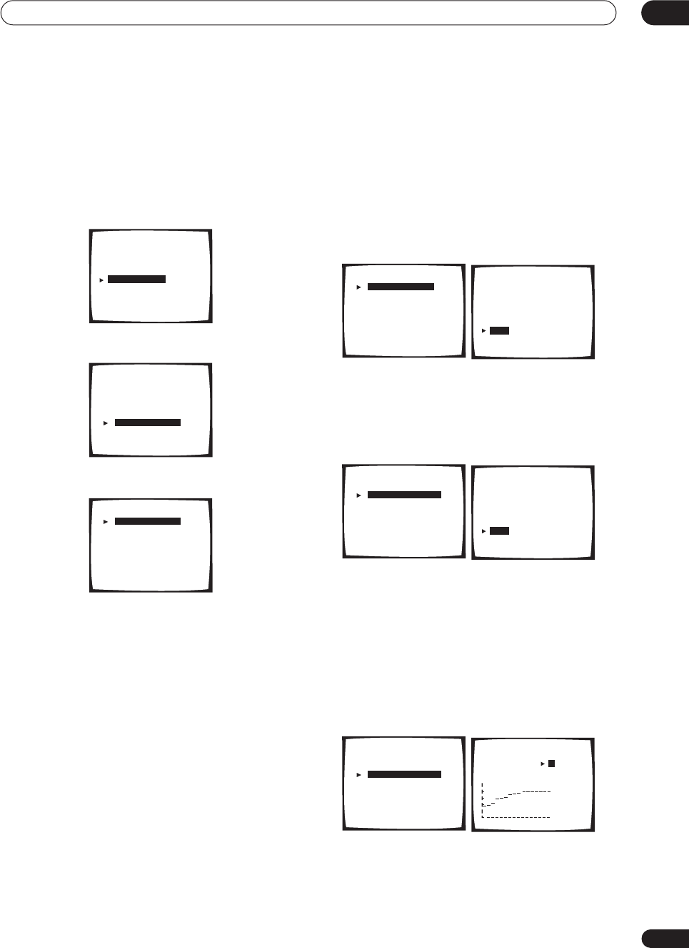
Advanced setup 11
85
En
Note that changing the room (for example, moving
furniture or paintings) will affect the calibration results.
In such cases, you should recalibrate your system.
Using Professional Acoustic Calibration
1 Select ‘Acoustic Cal EQ’ from the Expert setup
menu.
2 Select ‘Professional’.
3 Select a setup option.
•
Auto Pro.
– This is the recommended setup when
using the Professional Acoustic Calibration. If you
feel confident with a setup that’s more involved, you
can use an advanced setup below. With this setup,
the receiver automatically sets an early time period
(20–40 ms or 60–80 ms) for reverb measurement,
giving you a system calibration based on the direct
sound coming from the speakers. The frequency
balance for each channel is then adjusted to
minimize the effect of the room characteristics on the
overall sound.
•
Reverb Measurement
– Use this to measure the
reverb characteristics of your room for each channel
in select frequency ranges. Since this measurement
is also made in
Auto Pro
(above), there is no need to
do this again if you were satisfied with the results.
•
Reverb View
– You can check the reverb
measurements made for specified frequency ranges
in each channel.
•
PC Output
– See
Connecting a PC for Advanced
MCACC output
on page 73 for more on this option.
•
Advanced EQ Setup
– Use this to select the time
period that will be used for frequency adjustment and
calibration, based on the reverb measurement of
your listening area. Note that this advanced setup is
not necessary if you’re satisfied with the results of
Automatically setting up for surround sound
on
page 12 or
Auto Pro
above (your previous settings
will be altered with this setup).
4If you selected ‘Auto Pro.’, select ‘Start’ and press
ENTER.
!! Complete !!
is displayed on-screen after the Acoustic
Calibration Equalization is set. Select
Exit
to return to the
Professional Acoustic Calibration menu.
5 If you selected ‘Reverb Measurement’, select
‘Start’ and press ENTER.
!! Complete !!
is displayed on screen when the reverb
measurement is finished (this may take 2–6 minutes).
After selecting
Exit
, you can select
Reverb View
to see
the results on-screen. See
Connecting a PC for Advanced
MCACC output
on page 73 for more on setting up your
computer for the graphical output.
6 If you selected ‘Reverb View’, you can use the
cursor buttons (buttons) to check the reverb
characteristics for each channel. Select ‘Exit’ when
you’re done.
Use the
/
(cursor up/down) buttons (and
ENTER
) to
select the channel and the frequency you want to check.
Note that the markers on the vertical axis indicate
decibels in 2dB steps.
Expert
[ Crossover Network ]
[ Fine Channel Level ]
[ Fine Channel Delay ]
[ Acoustic Cal EQ ]
[ Bass Peak Level ]
[ D-Range Control ]
[ Exit ]
[ EQ AUTO SETTING ]
[ CUSTOM1 ADJUST ]
[ CUSTOM2 ADJUST ]
[ DATA COPY ]
[ DATA CHECK ]
[ Professional ]
[
Exit
]
Acoustic Cal EQ
[ Auto Pro. ]
[ Reverb Measurement ]
[ Reverb View ]
[ PC Output ]
[ Advanced EQ Setup ]
[
Exit
]
Acoustic Cal EQ Pro.
[ Auto Pro. ]
[ Reverb Measurement ]
[ Reverb View ]
[ PC Output ]
[ Advanced EQ Setup ]
[
Exit
]
Acoustic Cal EQ Pro. Acoustic Cal EQ Pro.
Auto Pro.
• Set microphone
• Turn on subwoofer
[ Start ]
[ Cancel ]
[ Auto Pro. ]
[ Reverb Measurement ]
[ Reverb View ]
[ PC Output ]
[ Advanced EQ Setup ]
[
Exit
]
Acoustic Cal EQ Pro. Acoustic Cal EQ Pro.
Reverb
• Set microphone
• Turn on subwoofer
[ Start ]
[ Cancel ]
[ Auto Pro. ]
[ Reverb Measurement ]
[ Reverb View ]
[ PC Output ]
[ Advanced EQ Setup ]
[
Exit
]
Acoustic Cal EQ Pro. Acoustic Cal EQ Pro.
Reverb Vew
[ L ]
[ 63Hz ]
dB
[ Exit ]
0 80 160ms
VSX-9300.book 85 ページ 2004年5月21日 金曜日 午前11時28分
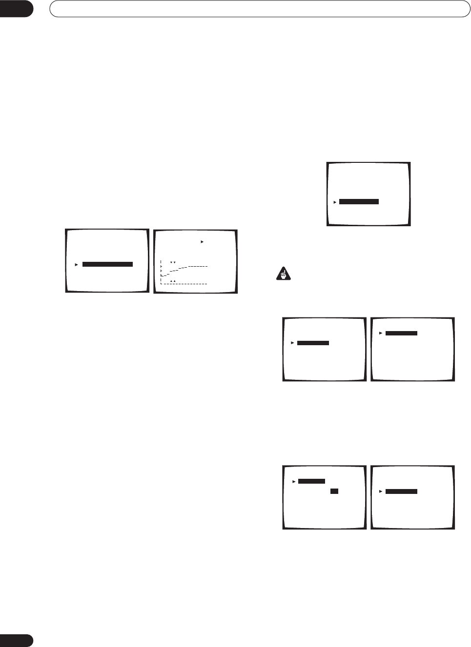
Advanced setup
11
86
En
• If
No Data
is displayed, you will need to make a
reverb measurement using the Auto Pro or Reverb
Measurement setup option.
7 If you selected ‘Advanced EQ Setup’, input the
time setting you want to use for calibration, then
select ‘Start’.
After checking on the reverb measurement above, you
may want to manually choose the time period that will be
used for the final frequency adjustment and calibration.
Even though you can make this setting without reverb
measurement, it is best to use the measurement results
as a reference for your time setting. For an optimal
system calibration based on the direct sound coming
from the speakers, we recommend using the
20–40ms
setting.
• If
No Data
is displayed, you will need to make a
reverb measurement using the Auto Pro or Reverb
Measurement setup option.
Use the
/
(cursor up/down) buttons to select the
channel, frequency, and time setting. Use the
/
(cursor up/down) buttons to switch between them.
You can switch between your connected speakers
(excluding the subwoofer), and display the
measurements for the following frequencies: 63Hz, 125
Hz, 250Hz, 1kHz, 4kHz and 11.3kHz.
• Note that six bands are available for measurement
and analysis here, but you will only be able to set five
bands when using
Acoustic Calibration EQ
on
page 81. The 1kHz band acts as a reference setting
(to ensure optimal adjustment of the other frequency
settings) for a total of six band adjustment.
Select the setting from the following time periods (in
milliseconds): 0–20ms, 10–30ms, 20–40ms, 30–50ms,
40–60ms, 50–70ms and 60–80ms. This setting will be
applied to all channels during calibration.
When you’re finished, select
Start
. It will take about 2–11
minutes for the calibration to finish.
!! Complete !!
is displayed on-screen after the Acoustic
Calibration Equalization is set. If you want to check the
settings, select
Check
and press
ENTER
. If you want to
finish, select
Exit
to exit each screen.
Bass Peak Level
Some audio sources (for example, Dolby Digital and DTS)
include ultra-low bass tones. Set the bass limiter as
needed to prevent the bass from distorting the sound
from the subwoofer.
1 Select ‘Bass Peak Level’ from the Expert setup
menu.
The current setting is displayed.
• When
[OFF]
is displayed the attenuator is off (bass
output is not affected).
Important
• When
[-80]
is displayed, no bass is output.
2 Select a setup option.
•
Setting Start
– The volume is set to -80dB, a test tone
plays back and you make the setting.
•
Setting Cancel
– Switches limiting off.
3 If you selected ‘Setting Start’, use the
/
(cursor up/down) buttons to adjust the test tone and
specify the bass peak level then press ENTER.
Set the bass peak level gradually, then press
ENTER
at
the point just before the tone starts to distort. When
you’re finished, the display on the receiver will show
RESUME
and the volume will return to its original
position.
• Press
RETURN
at any time to exit without setting the
bass peak level.
• If your subwoofer has an Auto Sleep feature, make
sure the subwoofer is active (not in standby).
[ Auto Pro. ]
[ Reverb Measurement ]
[ Reverb View ]
[ PC Output ]
[ Advanced EQ Setup ]
[
Exit
]
Acoustic Cal EQ Pro. Acoustic Cal EQ Pro.
[ L ]
[ 63Hz ]
[ 20–40ms ]
[ Start ]
[ Exit ]
dB
0 80 160ms
Expert
[ Crossover Network ]
[ Fine Channel Level ]
[ Fine Channel Delay ]
[ Acoustic Cal EQ
]
[ Bass Peak Level ]
[ D-Range Control ]
[ Exit ]
Bass Peak Level
[ Setting Start ]
[ Setting Cancel ]
[ Exit ]
Present Level [OFF]
Bass Peak Level
[ Setting Start ]
[ Setting Cancel ]
[ Exit ]
Please Wait
Bass Peak Level
[Setting OK ]
Bass Peak Level
[–80]
Bring up the Bass
Peak Level To
a comfortable Volume
(–80=no sound)
Bass Peak Level
[ Setting Start ]
[ Setting Cancel ]
[ Exit ]
Present Level [-30]
VSX-9300.book 86 ページ 2004年5月21日 金曜日 午前11時28分
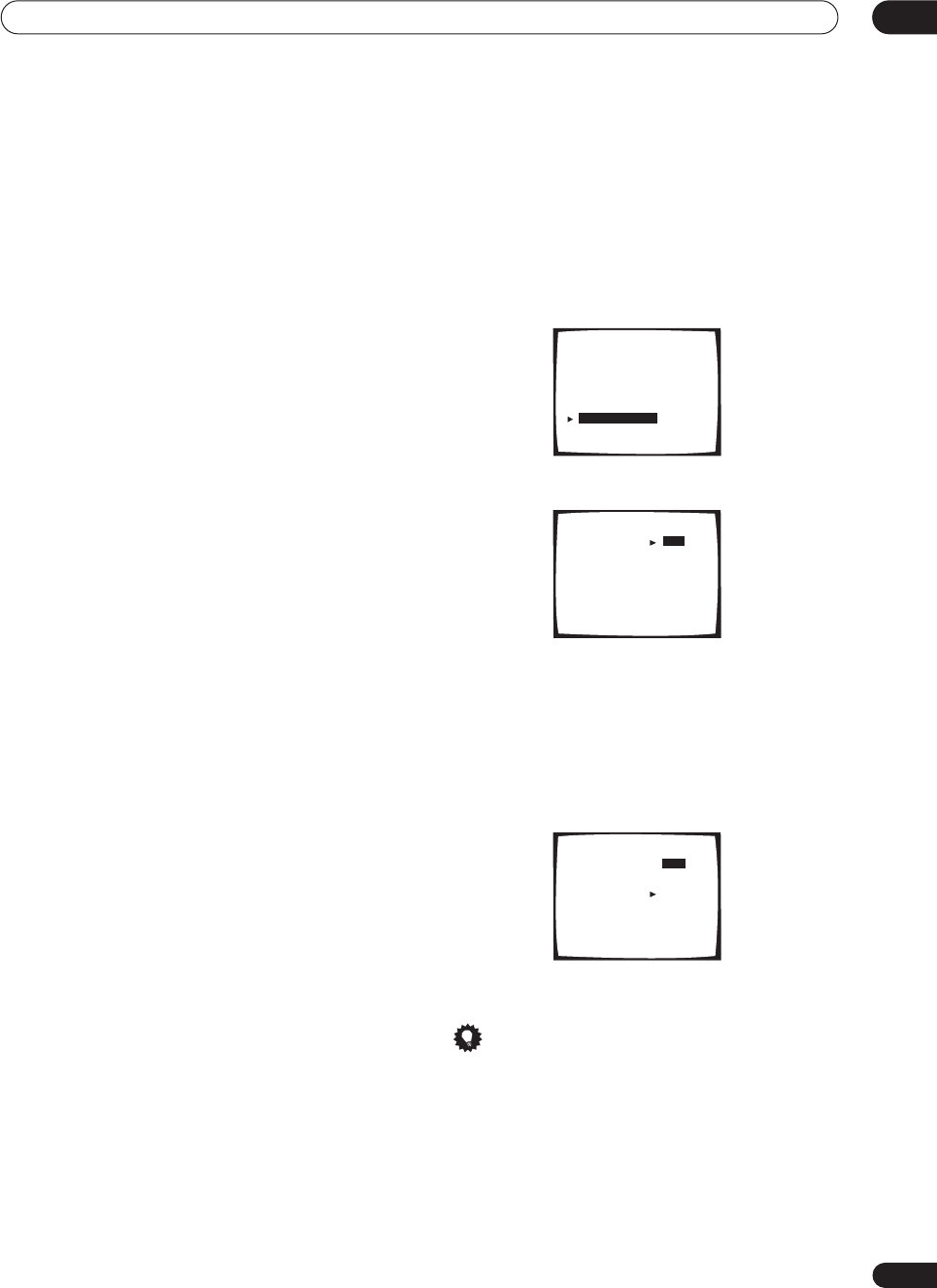
Advanced setup 11
87
En
• If the
YES
or
PLUS
setting on the subwoofer is
selected (in
Speaker Setting
on page 51), the test tone
will only play back from the subwoofer. If not, the test
tone will play back from the front and surround
speakers set to
LARGE
.
4 When you're finished, select ‘Exit’.
You will return to the Expert setup menu.
Dynamic Range Control
• Default setting:
OFF
This setting specifies the amount of dynamic range
adjustment to Dolby Digital and DTS movie soundtracks.
You may want to use this when listening to surround
sound at low volumes.
1 Select ‘D-Range Control’ from the Expert setup
menu.
2 Choose the setting that you want.
•
OFF
– No dynamic range adjustment (use when
listening at higher volume).
•
MID
– Mid setting.
•
MAX
– Dynamic range is reduced (loud sounds are
reduced in volume while quieter sounds are
increased)
3 When you're finished, select ‘Exit’.
You will return to the Expert setup menu.
Tip
• For general dynamic range control, you can use the
Midnight listening mode (see
Using Midnight and
Loudness listening
on page 45) on a variety of
sources that are not Dolby Digital or DTS encoded.
Expert
[ Crossover Network ]
[ Fine Channel Level ]
[ Fine Channel Delay ]
[ Acoustic Cal EQ
]
[ Bass Peak Level ]
[ D-Range Control ]
[ Exit ]
Dynamic Range Control
Select Mode [ OFF ]
dts [
MID
]
[
MAX
]
[
Exit
]
Dynamic Range Control
Select Mode [ OFF ]
dts [
MID
]
[
MAX
]
[
Exit
]
VSX-9300.book 87 ページ 2004年5月21日 金曜日 午前11時28分
Additional information
12
88
En
Chapter 12
Additional information
Troubleshooting
Incorrect operations are often mistaken for trouble and malfunctions. If you think that there is something wrong with
this component, check the points below. Sometimes the trouble may lie in another component. Investigate the other
components and electrical appliances being used. If the trouble cannot be rectified even after exercising the checks
listed below, ask your nearest Pioneer authorized independent service company to carry out repair work.
Power
Symptom Cause Remedy
The power does not turn on. • The power plug is disconnected. • Connect the power plug to the wall outlet.
• The protection circuit may have been
activated. • Disconnect the power plug from the outlet, and insert
again.
• Something is obstructing the rear panel
ventilation device. • Unplug the receiver from the wall and call a Pioneer
authorized independent service company.
The receiver suddenly switches
off. • The speaker wires are frayed or sticking out
of the jack, and are touching the back of the
receiver or another set of wires.
• Reinsert the speaker wires, making sure there are no
stray strands of wire and that they are inserted fully.
• The receiver has a serious problem. • Unplug the receiver from the wall and call a Pioneer
authorized independent service company.
During loud playback the power
suddenly switches off. • The protection circuit has been activated
because the lowest actual impedance of the
speakers (as opposed to the speakers rated
impedance) is dangerously low.
• Turn down the volume.
• When it’s convenient, go to
Acoustic Calibration EQ
on
page 81 and lower the 63 Hz and 125 Hz equalizer levels
using the manual setting.
• Turning the digital safety feature on may allow you to
turn up the volume a little more. To switch between
SAFETY ON
and
SAFETY OFF
, put the receiver into
standby, then press the
STANDBY/ON
button while
holding down the
MULTI JOG CONTROL SET UP
button
on the front panel.
The unit does not respond when
the buttons are pressed. • Static electricity caused by dry air. • Switch the unit off, then on again.
• Disconnect the power plug from the outlet, and insert
again.
AMP ERR
blinks in the display,
then the power automatically
switches off.
• The receiver has a serious problem. • After about a minute (you won’t be able to switch the
unit on during this time), switch the receiver back on. If
the message persists, call a Pioneer authorized
independent service company.
FAN STOP
blinks in the display,
then the power automatically
switches off.
• Something is obstructing the fan. • Remove the obstruction and try switching the receiver
back on. If the fan is still not working, or you can’t remove
the object, unplug the receiver from the wall and call a
Pioneer authorized independent service company.
• The fan is malfunctioning. • Unplug the receiver from the wall and call a Pioneer
authorized independent service company.
OVERHEAT
blinks in the display
and no sound is output. • The internal temperature of the unit has
become too high. • After allowing the unit to cool down in a well-ventilated
place, try switching the receiver back on. Make sure you
follow the guidelines for improving heat dispersal in
Ventilation
on page 7.
THDCT NG
blinks in the display
and the unit turns off. • The thermistor (temperature sensor) is
broken. • Turn the receiver off, unplug from wall and call a Pioneer
authorized independent service company to look at the
problem.
VSX-9300.book 88 ページ 2004年5月21日 金曜日 午前11時28分
Additional information 12
89
En
No sound
Symptom Cause Remedy
No sound is output when an
input source is selected. • Improper connections. • Make sure you have properly connected the component
to the corresponding input on the back of the receiver
(see
Connecting your equipment
on page 15).
• Sound is muted or the volume is turned
down. • Press
MUTE
or adjust the volume accordingly.
• Speakers are turned off or selected
improperly with the
SPEAKERS
switch. • Press
SPEAKERS
to select the proper speaker set (see
Switching the speaker system
on page 67).
• The input signal type is incorrect. • Press
SIGNAL SELECT
to select the proper input signal
(see
Selecting the input signal type
on page 42).
• The multichannel analog inputs are
selected. • Press
MULTI CH INPUT
again (see
Using the
multichannel analog inputs
on page 41).
No sound output from the front
speakers. • The front speakers aren’t connected
properly. • See
Installing your speaker system
on page 28 to
connect them properly.
No sound from the surround or
center speakers. • Speaker settings are incorrect. (for
example, they have been set to
NO
). • Check you speaker settings in
Speaker Setting
on
page 51.
• The surround and/or center levels are
turned down. • Check the levels in
Channel Level
on page 52.
• The surround and/or center speakers aren’t
connected properly. • Check
Installing your speaker system
on page 28 to
make sure the speakers are connected correctly.
• The
STEREO
listening mode has been
selected. • Choose a surround listening mode (see
Listening in
surround sound
on page 37).
No sound from surround back
speakers. • Surround back speakers are set to
NO
.• Set the surround back speakers to
LARGE
or
SMALL
(see
Speaker Setting
on page 51).
• The
SB CH
mode is switched off
.
• Set the surround back channel to
SB CH ON
(see
page 43).
• The source is not a 6.1 channel playback
source. • Choose an advanced effect listening mode (see
Listening in surround sound
on page 37).
• The surround back speakers aren’t
connected properly. • Check
Installing your speaker system
on page 28 to
make sure the speakers are connected correctly.
• The surround back channel is on the 1
speaker setting, and your speaker is
connected to the right channel output.
• Connect the speaker to the surround back left channel
output (
Installing your speaker system
on page 28).
• The
SB CH MODE
is switched to
AUTO
and
the Dolby Surround EX / DTS ES software
you’re playing has no flag to indicate it is 6.1
compatible.
• You can still listen with surround back sound by setting
the surround back channel to
SB CH ON
(page 43).
No sound from subwoofer. • The bass attenuator is set too low (for
example, the
-80
setting). • See
Bass Peak Level
on page 86 to adjust the setting.
• The subwoofer isn’t connected properly, or
it is switched off. • Connect or switch on the subwoofer (see
Installing your
speaker system
on page 28).
• Make sure the sleep function on your subwoofer isn’t
activated.
• The subwoofer's settings are incorrect. • Set the subwoofer (see
Speaker Setting
on page 51) to
YES
or
PLUS
.
• The crossover frequency is set too low. • Set the crossover frequency to a (higher) frequency that
matches your speaker characteristics (see
Crossover
Network
on page 80)
• There is very little low frequency information
in your source. • Change your subwoofer setting to one of the following in
the
Speaker Setting
on page 51:
Front:
SMALL
/ Subwoofer:
YES
Front:
LARGE
/ Subwoofer:
PLUS
• The subwoofer's levels are too low. • See
Channel Level
on page 52 to check the speaker
levels.
• Check the volume control on the subwoofer to make
sure it is turned up.
VSX-9300.book 89 ページ 2004年5月21日 金曜日 午前11時28分
Additional information
12
90
En
Other audio problems
No sound from one speaker. • The speaker setting has been set to
NO
.• Change the setting in
Speaker Setting
on page 51.
• The speaker level is too low. • Check the level in
Channel Level
on page 52.
• The speaker isn’t connected properly. • Check
Installing your speaker system
on page 28 to
make sure the speaker is connected correctly.
• The source has no sound output for that
channel. • By choosing an advanced effect listening mode (see
Listening in surround sound
on page 37), you may be able
to create an extra channel for the speaker.
Sound is produced from analog
components, but not from digital
ones (DVD, LD, CD-ROM etc.).
• The digital input assignment is wrong. • Assign the digital inputs correctly (see
Assigning the
digital inputs
on page 75).
• The digital components aren't connected
properly. • Make sure you have properly connected the digital
component to the corresponding input on the back of the
receiver (see
Connecting your equipment
on page 15).
• The player is not compatible with the source
you're using, or the player settings are
incorrect.
• Choose a compatible source, or check the component’s
manual for the correct settings.
• The digital output level has been turned
down on a CD player or other component
equipped with digital output level adjustment
capability.
• Set the digital volume level of the player to full, or to the
neutral position.
• The multichannel analog inputs are
selected. • Press
MULTI CH INPUT
again (see
Using the
multichannel analog inputs
on page 41).
• The input signal type is set to
ANALOG
.• Set the input signal type to
DIGITAL
(see
Selecting the
input signal type
on page 42).
No sound is output or a noise is
output when Dolby Digital/DTS
software is played back.
• A DVD player not compatible with Dolby
Digital/DTS is being used. • Make sure your DVD player is compatible with Dolby
Digital/DTS.
• The settings on the DVD player are incorrect
and/or the DTS signal output is turned off. • Make sure the player's settings are correct and/or the
DTS signal out is on. Refer to the instruction manual
supplied with the DVD player.
• The digital output level is turned down on a
CD player or other component equipped with
digital output level adjustment capability. (The
DTS signal has been altered by the player, and
cannot be read.)
• Set the digital volume level of the player to full, or to the
neutral position.
Symptom Cause Remedy
Symptom Cause Remedy
Broadcast stations cannot be
selected automatically, or there
seems to be considerable noise
in radio broadcasts.
FM broadcasts
• The FM antenna is not fully extended or is
poorly positioned. • Fully extend the FM wire antenna, position for best
reception, and secure to a wall.
• Weak radio signals. • Connect an outdoor FM antenna (see page 30).
AM broadcasts
• The AM antenna is poorly positioned. • Adjust the direction and position for best reception.
• Weak radio signals. • Connect an additional internal or external AM antenna
(see page 30).
• Interference caused by other equipment
(fluorescent lamp, motor, etc.). • Turn off the equipment causing the noise or move it
away from the receiver.
• Place the antenna farther away from the equipment
causing the noise.
A multi channel DVD source
appears to be downmixed from 2
channels during playback.
• The source is coming from something other
than the
MULTI CH IN
jacks (for example,
digital PCM output, etc.)
• Check the
MULTI CH IN
connection (see
Connecting the
multichannel analog outputs
on page 20) and select the
multichannel analog inputs with the
MULTI CH IN
button
(see
Using the multichannel analog inputs
on page 41).
Noise is output when scanning a
DTS CD. • The scan function performed by the player
slightly alters the digital information, making
it unreadable.
• This is not a malfunction, but be sure to turn the volume
down to prevent the output of loud noise from your
speakers.
When playing a DTS format LD
there is audible noise on the
soundtrack.
• The input signal type is set to
ANALOG
.• Set the input signal type to
DIGITAL
(see
Selecting the
input signal type
on page 42)
VSX-9300.book 90 ページ 2004年5月21日 金曜日 午前11時28分
Additional information 12
91
En
Video
Can't record audio. • You are trying to make an analog recording
from a digital signal, or a digital recording of
an analog source.
•You can only record analog to analog, or digital to digital.
• The digital source is copy protected. • You can't record digital sources that have been copy
protected.
• The analog
REC
jacks have not been
connected properly. • Check your analog connections (see
Connecting analog
audio sources
on page 26).
Subwoofer output is very low. • The bass attenuator is set too low. • See
Bass Peak Level
on page 86 to adjust the setting.
• The speaker settings result in very little
audio signal being sent to the subwoofer. • Change your subwoofer setting to one of the following in
the
Speaker Setting
on page 51:
Front:
SMALL
/ Subwoofer:
YES
Front:
LARGE
/ Subwoofer:
PLUS
Everything seems to be set up
correctly, but the playback sound
is odd.
• The speakers are out of phase. • Check that the positive/negative speaker terminals on
the receiver are matched with the corresponding
terminals on the speakers (page 28).
Noise or hum can be heard even
when there is no sound being
input.
• There is electrical interference from another
component or appliance. • Check that personal computers or other digital
components connected to the same power source are not
causing interference.
There seems to be a time lag
between the speakers and the
output of the subwoofer.
• The subwoofer channel can be delayed
slightly if run through a low-pass filter. • See
Automatically setting up for surround sound
on
page 12 to set up your system again using MCACC (this
will automatically compensate for a delay in the
subwoofer output).
Symptom Cause Remedy
Symptom Cause Remedy
No image is output when an
input is selected. • The video connections are incorrect. • Make sure the video component is connected correctly
(see pages 19–27).
• You are using component video
connections for your source, but not for your
TV.
• Using the video converter, video signals can be
converted from a composite or S-video input to a
component video output, but not vice-versa. See
About the
video converter
on page 16 for more on this.
• You are using component video
connections and the component video inputs
are assigned incorrectly.
• Check
Assigning the component video inputs
on page 76
to make sure you’re assigned the correct input.
• The DVD/video player settings are incorrect. • Set correctly. Refer to the instruction manual supplied
with the DVD/video player.
• The video input selected on the TV monitor
is incorrect. • Set correctly. Refer to the instruction manual supplied
with the TV.
• Even though the sub room monitor is
connected properly, the multi-room feature is
switched off.
• Press the
MULTI ROOM&SOURCE ON/OFF
button to
switch it on.
• The component video inputs are assigned
to a video component connected only to the
composite or S-Video terminals.
• Check
Assigning the component video inputs
on page 76
to make sure the component video assign for that video
component is switched to
OFF
.
The
System Setup
screen
doesn't appear. • The
MONITOR OUT
jack hasn't been
connected.
• You connected your TV to the
MULTI ROOM
& SOURCE MONITOR OUT
jack instead of
the main
MONITOR OUT
jack.
• Connect the
MONITOR OUT
jack to the TV monitor (see
Connecting your TV
on page 18).
• Some TVs connected to the receiver with
component video cables do not display the
System Setup
screen when the Color Burst
feature is on.
• When the receiver is in standby, switch to
COLOR
BURST OFF
by holding down the
MULTI JOG CONTROL
RETURN
button and pressing
STANDBY/ON
. (the
current setting appears in the display).
Screen noise when playing back
a video source. • The video source signal has a problem. • If your video connections use mixed cable types (for
example RCA standard video to a component video
connection), you may want to try connecting your system
using only one cable type (for example, use RCA standard
video cable for all connections).
VSX-9300.book 91 ページ 2004年5月21日 金曜日 午前11時28分
Additional information
12
92
En
Settings
Display
Can’t record video. • You are trying to record a source connected
to the component video jacks. • Connect the source component to either the composite
video or the S-video jacks (see
Connecting your equipment
on page 15).
• The source is copy protected. • You can't record sources that have been copy protected.
• The recorder's video input is hooked up
using a different type of cable to the source
video output.
• Hook up the source and the recorder using the same
type of video cable (see
Making an audio or a video
recording
on page 62).
Symptom Cause Remedy
Symptom Cause Remedy
The Auto Surround Setup
continually shows an error. • The ambient noise level in the room is too
high, or obstacles are blocking the setup
microphone.
• Keep the noise level in the room as low as possible
when using the Auto Surround Setup (see
Other problems
when using the Auto Surround Setup
on page 14 for more
on this). If the noise cannot be kept low enough, you will
have to set up the surround sound manually (page 50).
After using the Auto Surround
Setup, the speaker size setting
(
LARGE
or
SMALL
) is incorrect.
• There was some inaudible low-frequency
noise in the room. • The low-frequency noise could have been caused by an
air conditioner or motor. Switch off all appliances in the
room and rerun the Auto Surround Setup.
The display shows
KEY LOCK
ON
when you try to make
settings.
• Your Pioneer dealer has enabled the key
lock feature. • Ask your Pioneer dealer to disable the key lock.
Symptom Cause Remedy
The display is dark or off. • The display is set to dark or off. • Press
DIMMER
on the remote control repeatedly to
select a different brightness.
After making an adjustment the
display goes off. • The display is set to off. • Press
DIMMER
on the remote control repeatedly to
select a different brightness.
You can't get
DIGITAL
to display
when using the
SIGNAL SELECT
button.
• There is a problem with the digital
connections or the digital input is assigned
incorrectly.
• Check your digital connections and/or assign the digital
inputs correctly (see
Assigning the digital inputs
on
page 75).
• The multichannel analog inputs are
selected. • Press
MULTI CH INPUT
again (see
Using the
multichannel analog inputs
on page 41).
The Dolby/DTS indicator doesn't
light when playing Dolby/DTS
software.
• The player is paused. • Press play.
• The player's sound output settings are
wrong. • Set the player correctly (consult the manual that came
with the player, if necessary).
When playing a DVD-Audio CD,
the DVD player display shows
96
kHz
. However, the receiver’s
display does not.
• The audio from these discs is output from
the analog audio jacks of the DVD player only;
the receiver does not show the sampling rate
of the input signal through the analog inputs.
• This is not a malfunction. See also the operating
instructions that came with your DVD player.
During playback of a DTS 96/24
source, the display doesn't show
96kHz
.
• The receiver’s input signal type is set to
analog. • Set the receiver to
AUTO
or
DIGITAL
(see
Selecting the
input signal type
on page 42).
When playing Dolby Digital or
DTS sources, the receiver’s
format indicators do not light.
• No digital connection, or the digital
connection is incorrect. • Check the digital audio connection (page 19).
• The receiver’s input signal type is set to
analog. • Set the receiver to
AUTO
or
DIGITAL
(see
Selecting the
input signal type
on page 42).
• The DVD player is set to output Dolby Digital
and/or DTS audio as PCM. • Check the settings on the player. Set the output for
Dolby Digital and DTS (no PCM conversion). See also the
operating instructions that came with your DVD player.
• The disc has several playback audio tracks;
the one currently playing is actually PCM. • Switch the playback audio channel on your DVD player.
See the operating instructions that came with your DVD
player.
When playing certain discs,
none of the receiver’s format
indicators light.
• The audio format of the disc is not 5.1/6.1
channel. • This is not a malfunction. Check the disc packaging for
details of the audio formats available on the disc.
VSX-9300.book 92 ページ 2004年5月21日 金曜日 午前11時28分
Additional information 12
93
En
Remote control
USB interface
When playing a disc, the
2
PRO LOGIC II
or
Neo:6
indicator lights on the receiver.
• The input signal type is set to analog. • Set the receiver to
AUTO
or
DIGITAL
(see
Selecting the
input signal type
on page 42).
• A 2 channel soundtrack is currently playing. • This is not a malfunction. Check the disc packaging for
details of the audio formats available on the disc.
• The soundtrack currently playing is
encoded using Dolby Surround. • This is not a malfunction. Check the disc packaging for
details of the audio formats available on the disc.
During playback of a Surround
EX or DTS ES source on the
SB
CH AUTO
setting, the
EX
and
ES
indicators don’t light, or the
signal is not properly processed.
•The source may be Dolby Surround EX / DTS
ES software, but it has no flag to indicate it is
6.1 compatible.
• Switch the surround back channel setting (page 43) to
SB CH ON
then switch to the THX Surround EX or
Standard EX listening mode (see
Listening in surround
sound
on page 37).
Symptom Cause Remedy
Symptom Cause Remedy
Cannot be remote controlled. • The remote control batteries have worn out. • Replace the batteries (see
Loading the batteries
on
page 7).
• Too far away or improper angle of operation. • Operate within 23 feet and a 30º angle of the remote
sensor on the front panel (see
Operating range of the
remote control
on page 8).
• There is an obstacle between the receiver
and the remote control. • Remove the obstacle or move to another place.
• Strong light such as fluorescent light is
shining onto the unit's remote control sensor. • Avoid exposing the remote sensor on the front panel to
direct light.
• Something is plugged into the
CONTROL IN
jack. • Unplug the cable from the
CONTROL IN
jack and use
remote normally (see
Operating other Pioneer components
with this unit’s sensor
on page 61).
• The IR receiver type is mismatched with the
setting. • Disconnect the IR receiver from the rear panel or set to
the other IR receiver type (see
Multi-Room and IR receiver
setup
on page 78).
Other components can't be
operated with the system
remote.
• The preset code settings are wrong. • Input the correct preset code.
• The batteries wore out and the system
settings were cleared. • Reset the proper system settings.
The SR cable is connected, but
the connected components can’t
be operated with the remote.
• The SR cable hasn't been connected
properly. • Reinsert the SR cable, making sure it’s connected to the
right jack (see
Operating other Pioneer components with
this unit’s sensor
on page 61).
• The rest of the component connections
have not been made. • Make sure an analog connection has been made
between the units.
• The component you have hooked up is not a
Pioneer product. • This feature only works with Pioneer products.
The remote control backlight is
switched on, but the
ENTER
button doesn’t light.
• This is not a malfunction. • This is a feature designed for quickly identifying the
remote control buttons in a dark room.
• For information about using the remote control in the sub room, please contact your local Pioneer dealer or the Pioneer Customer Support
division.
Symptom Cause Remedy
No sound. • The computer settings are incorrect. • Make sure you have set up your computer system to
output through the USB interface (see
Using the USB
interface
on page 72).
• The software or source material you are
using is not compatible with USB output. • Update to a more recent version of your existing
software, try a different audio program, or try a different
source.
• The volume control on your computer is set
too low. • Turn up the volume on your computer.
VSX-9300.book 93 ページ 2004年5月21日 金曜日 午前11時28分

Additional information
12
94
En
Note
• If the unit does not operate normally due to external
effects such as static electricity, disconnect the
power plug from the outlet and insert again to return
to normal operating conditions.
VSX-9300.book 94 ページ 2004年5月21日 金曜日 午前11時28分
Additional information 12
95
En
Surround sound formats
Below is a brief description of the main surround sound
formats you’ll find on DVDs, satellite, cable and
terrestrial broadcasts, and video cassettes.
Dolby
The Dolby technologies are explained below. See
www.dolby.com for more detailed information.
Dolby Digital
Dolby Digital is a multichannel digital audio coding
system widely used in cinemas, and in the home for DVD
and digital broadcast soundtracks. It can deliver up to six
discrete audio channels, comprising five full range
channels and a special LFE (low frequency effects)
channel used mainly for deep, rumbling sound effects;
hence the term “5.1-channel” Dolby Digital.
In addition to the format features above, Dolby Digital
decoders offer downmixing for compatibility with mono,
stereo and Dolby Pro Logic audio from a number of bit
rates and channels. Another feature, called Dialog
Normalization, attenuates programs based on the
average level of dialog in a program relative to its peak
level (also known as Dialnorm) in order to achieve
uniform playback level.
Dolby Digital Surround EX
Dolby Digital Surround EX (the EX stands for EXtended)
is an extension of Dolby Digital encoding whereby a
surround back channel is matrixed into the surround left/
right channels for 6.1 channel playback. This allows for
compatibility with Dolby Digital 5.1 channel decoding, as
well as for decoding using Dolby Digital EX.
Dolby Pro Logic IIx and Dolby Surround
Dolby Pro Logic IIx is an improved version of the Dolby
Pro Logic II (and Dolby Pro Logic)
decoding
system. Using
the innovative “steering logic” circuit, this system
extracts surround sound from sources as follows:
•
Dolby Pro Logic
– 4.1 channel sound (mono
surround) from any stereo source
•
Dolby Pro Logic II
– 5.1 channel sound (stereo
surround) from any stereo source
•
Dolby Pro Logic IIx
– 6.1 or 7.1 channel sound
(stereo surround and surround back) from two
channel or 5.1(and 6.1) channel sources
With two channel sources, the “.1” subwoofer channel is
generated by bass management in the receiver.
Dolby Surround is an
encoding
system which embeds
surround sound information within a stereo soundtrack,
which a Dolby Pro Logic decoder can then use for
enhanced surround listening with greater sound detail.
Manufactured under license from Dolby Laboratories.
"Dolby", "Pro Logic", “Surround EX” and the double-D
symbol are trademarks of Dolby Laboratories.
DTS
The DTS technologies are explained below. See
www.dtstech.com for more detailed information.
DTS Digital Surround
DTS Digital Surround is a 5.1-channel audio coding
system from Digital Theater Systems Inc. now widely
used for DVD-Video, DVD-Audio, 5.1 music discs, digital
broadcasts, and video games. It can deliver up to six
discrete audio channels, comprising five full range
channels, including an LFE channel. Higher sound
quality is achieved through the use of a low compression
rate, and high rates of transmittance during playback.
DTS-ES
DTS-ES (the ES stands for Extended Surround) is a
decoder that is capable of decoding both DTS-ES
Discrete 6.1 and DTS-ES Matrix 6.1 encoded sources.
DTS-ES Discrete 6.1 gives ‘true’ 6.1 channel sound, with
a completely separate (discrete) surround back channel.
DTS-ES Matrix 6.1 has a surround back channel matrixed
into the surround left/right channels. Both sources are
also compatible with a conventional DTS 5.1 channel
decoder.
DTS Neo:6
DTS Neo:6 can generate 6.1 channel surround sound
from any matrixed stereo source (such as video or TV)
and from 5.1 channel sources. It uses both the channel
information already encoded into the source, as well as
its own processing to determine channel localization
(with two channel sources, the “.1” subwoofer channel is
generated by bass management in the receiver). Two
modes (Cinema and Music) are available using DTS
Neo:6 with two channel sources.
DTS 96/24
DTS 96/24 is an extension of the original DTS Digital
Surround which offers high quality 96 kHz / 24-bit audio
using a DTS 96/24 decoder. This format is also fully
backward compatible with all existing decoders. This
means that DVD players can play this software using a
conventional DTS 5.1 channel decoder.
“DTS”, “DTS-ES”, “Neo:6” and “DTS 96/24” are trademarks
of Digital Theater Systems, Inc.
VSX-9300.book 95 ページ 2004年5月21日 金曜日 午前11時28分

Additional information
12
96
En
About THX
The THX technologies are explained below. See
www.thx.com for more detailed information.
THX Cinema processing
THX is an exclusive set of standards and technologies
established by the world-renowned film production
company, Lucasfilm Ltd. THX grew from George Lucas'
personal desire to make your experience of the film
soundtrack, in both movie theatres and in your home
theatre, as faithful as possible to what the director
intended. Movie soundtracks are mixed in special movie
theatres called dubbing stages and are designed to be
played back in movie theatres with similar equipment
and conditions. This same soundtrack is then
transferred directly onto Laserdisc, VHS tape, DVD, etc.,
and is not changed for playback in a small home theatre
environment. THX engineers developed patented
technologies to accurately translate the sound from the
movie theatre environment into the home, correcting the
tonal and spatial errors that occur. On this product, when
the THX indicator is on, THX features are automatically
added in Cinema modes (e.g. THX Cinema, THX
Surround EX).
Re-Equalization
The tonal balance of a film soundtrack will be excessively
bright and harsh when played back over audio
equipment in the home because film soundtracks were
designed to be played back in large movie theaters using
very different professional equipment. Re-Equalization
restores the correct tonal balance for watching a movie
soundtrack in a small home environment.
Timbre Matching
The human ear changes our perception of a sound
depending on the direction from which the sound is
coming. In a movie theatre, there is an array of surround
speakers so that the surround information is all around
you. In a home theatre, you use only two speakers located
to the side of your head. The Timbre Matching feature
filters the information going to the surround speakers so
that they more closely match the tonal characteristics of
the sound coming from the front speakers. This ensures
seamless panning between the front and surround
speakers.
Adaptive Decorrelation
In a movie theatre, a large number of surround speakers
help create an enveloping surround sound experience,
but in a home theatre there are usually only two speakers.
This can make the surround speakers sound like
headphones that lack spaciousness and envelopment.
The surround sounds will also collapse into the closest
speaker as you move away from the middle seating
position. Adaptive Decorrelation slightly changes one
surround channel's time and phase relationship with
respect to the other surround channel. This expands the
listening position and creates—with only two speakers—
the same spacious surround experience as in a movie
theatre.
THX Select
Before any home theatre component can be THX Select
certified, it must incorporate all the features above and
also pass a rigorous series of quality and performance
tests. Only then can a product feature the THX Select
logo, which is your guarantee that the Home Theatre
products you purchase will give you superb performance
for many years to come. THX Select requirements cover
every aspect of the product including pre-amplifierand
power amplifier performance and operation, and
hundreds of other parameters in both the digital and
analog domain.
THX Surround EX
THX Surround EX - Dolby Digital Surround EX is a joint
development of Dolby Laboratories and the THX Ltd. In a
movie theater, film soundtracks that have been encoded
with Dolby Digital Surround EX technology are able to
reproduce an extra channel which has been added
during the mixing of the program. This channel, called
Surround Back, places sounds behind the listener in
addition to the currently available front left, front center,
front right, surround right, surround left and subwoofer
channels. This additional channel provides the
opportunity for more detailed imaging behind the listener
and brings more depth, spacious ambience and sound
localization than ever before. Movies that were created
using the Dolby Digital Surround EX technology, when
released into the home consumer market may exhibit
wording to that effect on the packaging. A list of movies
created using this technology can be found on the Dolby
web site at www.dolby.com.
Only receiver and controller products bearing the THX
Surround EX logo, when in the THX Surround EX mode,
faithfully reproduce this new technology in the home.
This product may also engage the “THX Surround EX”
mode during the playback of 5.1 channel material that is
not Dolby Digital Surround EX encoded. In such case the
information delivered to the Surround Back channel will
be program dependent and may or may not be very
pleasing depending on the particular soundtrack and the
tastes of the individual listener.
THX is a trademark or registered trademark of THX Ltd.
Surround EX is a jointly developed technology of THX and
Dolby Laboratories and is a trademark of Dolby
Laboratories. Used under authorization. All rights reserved.
VSX-9300.book 96 ページ 2004年5月21日 金曜日 午前11時28分

Additional information 12
97
En
Preset code brands
DVD
Pioneer
Denon
JVC
Philips
Panasonic
RCA
Samsung
Sony
Toshiba
Yamaha
LD
Pioneer
Denon
Kenwood
Panasonic
Philips
Sony
Yamaha
CD-R
Pioneer
Denon
JVC
Kenwood
Philips
Sony
DVR
Pioneer
MD
Pioneer
Denon
JVC
Kenwood
Sony
Yamaha
CD
Pioneer
Denon
Fisher
JVC
Kenwood
Magnavox
Marantz
Onkyo
Panasonic
Philips
RCA
Sanyo
Sharp
Sony
TEAC
Technics
Yamaha
STB (Satellite/CATV)
Pioneer
Blaupunkt
General Instrument
Goldstar
Grundig
Hamlin
HNS/Hughes
Hitachi
ITT/Nokia
Jerrold
NEC
Oak
Panasonic
Philips
Radio Shack
RCA
Samsung
Scientific Atlanta
Siemens
Sony
Toshiba
Tocom
Zenith
Tape
Pioneer
Denon
Fisher
JVC
Kenwood
Nakamichi
Onkyo
Philips
Sony
TEAC
Technics
Yamaha
Tuner
Pioneer
VCR
Pioneer
Admiral
Aiwa
Akai
Alba
Audio Dynamic
Bell&Howell
Blaupunkt
Brocsonic
Bush
Canon
CGM
Citizen
Clatronic
Craig
Curtis Mathis
Daewoo
DBX
Dimensia
Emerson
Ferguson
Fisher
Funai
GE
Goldstar
Goodmans
Grundig
Hitachi
Instant Replay
ITT/Nokia
JC Penny
JVC
Kendo
Kenwood
Loewe
Luxor
LXI
Magnavox
Marantz
Marta
Matsui
Memorex
Minolta
Mitsubishi
Multitech
NEC
Nokia Oceanic
Nokia
Nordmende
Okano
Olympic
Orion
Panasonic
Pentax
Philco
Philips
Phonola
Quasar
RCA/Proscan
Realistic
Saba
Samsung
Sansui
Sanyo
Schneider
Scott
SEG
Seleco
Sharp
Siemens
Signature
Sony
Sylvania
Symphonic
Tandberg
Tashiro
Tatung
TEAC
Technics
Telefunken
Thorn
Toshiba
Universum
W.W House
Wards
Yamaha
Zenith
TV
Pioneer
Admiral
Aiwa
Akai
Alba
AOC
Bestar
Blaupunkt
Blue Sky
Brandt
Brocsonic
Bush
Clatronic
Craig
Croslex
Curtis Mathis
Daewoo
Daytron
Dual
Emerson
Ferguson
First
Fisher
Fujitsu
Funai
GE
Goldstar
Goodmans
Grandiente
Grundig
Hitachi
ICE
Irradio
ITT/Nokia
JC Penny
JVC
Kendo
KTV
Loewe
LXI
Magnavox
Mark
Matsui
Matsushita
Medion
Mitsubishi
Mivar
NEC
Nokia Oceanic
Nordmende
Okano
Onwa
Panasonic
Philco
Philips
Phonola
Portland
Proscan
Quasar
Radio
Radio Shack
Radiola
RCA/Proscan
Saba
Samsung
Sanyo
Schneider
Scott
Sharp
Siemens
Signature
Sony
Sylvania
Symphonic
Tatung
Telefunken
Thomson
Thorn
Toshiba
Universum
Videch
W.W House
Wards
Watson
Zenith
VSX-9300.book 97 ページ 2004年5月21日 金曜日 午前11時28分

Additional information
12
98
En
Specifications
Amplifier section
Continuous average power output of 110 watts* per
channel, min., at 8 ohms, from 20 Hz to 20,000 Hz with
no more than 0.09%** total harmonic distortion (front).
Continuous Power Output
Front. . . . . . . . . . . . . 110 W + 110 W (20 Hz-20 kHz, 0.09%)
Center . . . . . . . . . . . . . . . . . . . 110 W (20 Hz-20 kHz, 0.09%)
Surround . . . . . . . . . 110 W + 110 W (20 Hz-20 kHz, 0.09%)
Surround back . . . . 110 W + 110 W (20 Hz-20 kHz, 0.09%)
Audio Section
Input (Sensitivity/Impedance)
PHONO MM. . . . . . . . . . . . . . . . . . . . . . . . 4.7 mV/47 k
Ω
LINE . . . . . . . . . . . . . . . . . . . . . . . . . . . . . .335 mV/47 k
Ω
Frequency Response
PHONO MM. . . . . . . . . . . . 20 Hz to 20,000 Hz ± 0.3 dB
LINE . . . . . . . . . . . . . . . . . . . . .5 Hz to 100,000 Hz dB
Output (Level/Impedance)
LINE . . . . . . . . . . . . . . . . . . . . . . . . . . . . . 335 mV/2.2 k
Ω
Tone Control
BASS . . . . . . . . . . . . . . . . . . . . . . . . . . . ± 6 dB (100 Hz)
TREBLE . . . . . . . . . . . . . . . . . . . . . . . . . ± 6 dB (10 kHz)
LOUDNESS . . . . . . . . . . . . . +4/+2 dB (100Hz/10 kHz)
(at volume position -40dB)
Signal-to-Noise Ratio (IHF, short circuited, A network)
LINE . . . . . . . . . . . . . . . . . . . . . . . . . . . . . . . . . . . .101 dB
Signal-to-Noise Ratio [EIA, at 1W (1kHz)]
LINE . . . . . . . . . . . . . . . . . . . . . . . . . . . . . . . . . . . . .83 dB
* Measured pursuant to the Federal Trade Commission’s
Trade Regulation rule on Power Output Claims for Amplifiers
** Measured by Audio Spectrum Analyzer
Composite Video / S-Video Section
Input (Sensitivity/Impedance) . . . . . . . . . . . . . . .1 Vp-p/75
Ω
Output (Level/Impedance). . . . . . . . . . . . . . . . . .1 Vp-p/75
Ω
Signal-to-Noise Ratio . . . . . . . . . . . . . . . . . . . . . . . . . . .65 dB
Frequency Response . . . . . . . . . . . . . .5 Hz to 10 MHz dB
Component Video Section
Input (Sensitivity/Impedance) . . . . . . . . . . . . . . .1 Vp-p/75
Ω
Output (Level/Impedance). . . . . . . . . . . . . . . . . .1 Vp-p/75
Ω
Signal-to-Noise Ratio . . . . . . . . . . . . . . . . . . . . . . . . . . .65 dB
Frequency Response . . . . . . . . . . . . .5 Hz to 100 MHz dB
FM Tuner Section
Frequency Range . . . . . . . . . . . . . . . . 87.5 MHz to 108 MHz
Usable Sensitivity . . . . . Mono: 13.2 dBf, IHF (1.3 µV/75
Ω
)
50 dB Quieting Sensitivity . . . . . . . . . . . . . . .Mono: 20.2 dBf
Stereo: 38.6 dBf
Signal-to-Noise Ratio . . . . . . . . . . Mono: 73 dB (at 85 dBf)
Stereo: 70 dB (at 85 dBf)
Distortion . . . . . . . . . . . . . . . . . . . . . . . Stereo: 0.5% (1 kHz)
Alternate Channel Selectivity . . . . . . . . . . . 60 dB (400 kHz)
Stereo Separation . . . . . . . . . . . . . . . . . . . . . . . 40 dB (1 kHz)
Frequency Response . . . . . . . . . . . . 30 Hz to 15 kHz ± 1dB
Antenna Input . . . . . . . . . . . . . . . . . . . . . . 75
Ω
unbalanced
AM Tuner Section
Frequency Range . . . . . . . . . . . . . . . . .530 kHz to 1,700 kHz
Sensitivity (IHF, Loop antenna) . . . . . . . . . . . . . . . 350 µV/m
Selectivity . . . . . . . . . . . . . . . . . . . . . . . . . . . . . . . . . . . 25 dB
Signal-to-Noise Ratio . . . . . . . . . . . . . . . . . . . . . . . . . . 50 dB
Antenna . . . . . . . . . . . . . . . . . . . . . . . . . . . . . . Loop antenna
Miscellaneous
Power Requirements . . . . . . . . . . . . . . . . . .AC 120 V, 60 Hz
Power Consumption . . . . . . . . . . . . . . . . . . . . . . . . . . .600 W
Power Consumption in standby. . . . . . . . . . . . . . . . . . . 0.8W
AC outlet (switched) . . . . . . . . . . . . . . . . 100 W (0.8 A) MAX
Dimensions . . . . . . . . . . . . 420 (W)
×
188 (H)
×
464 (D) mm
(16-9/16 (W)
×
7-7/16 (H)
×
18-5/16 (D) in.)
Weight (without package) . . . . . . . . . . . . . .20.3 kg (44.8 lb)
Furnished Parts
Microphone . . . . . . . . . . . . . . . . . . . . . . . . . . . . . . . . . . . . . . 1
Microphone stand. . . . . . . . . . . . . . . . . . . . . . . . . . . . . . . . . 1
Remote control unit . . . . . . . . . . . . . . . . . . . . . . . . . . . . . . . 1
Alkaline batteries (AA IEC LR6)
. . . . . . . . . . . . . . . . . . . . 4
AM loop antenna. . . . . . . . . . . . . . . . . . . . . . . . . . . . . . . . . . 1
FM wire antenna . . . . . . . . . . . . . . . . . . . . . . . . . . . . . . . . . . 1
Power cord. . . . . . . . . . . . . . . . . . . . . . . . . . . . . . . . . . . . . . . 1
Warranty card . . . . . . . . . . . . . . . . . . . . . . . . . . . . . . . . . . . . 1
These operating instructions . . . . . . . . . . . . . . . . . . . . . . . . 1
Note
•Specifications and the design are subject to possible
modifications without notice, due to improvements.
Maintenance of external surfaces
•Use a polishing cloth or dry cloth to wipe off dust and
dirt.
• When the surfaces are dirty, wipe with a soft cloth
dipped in some neutral cleanser diluted five or six
times with water, and wrung out well, and then wipe
again with a dry cloth. Do not use furniture wax or
cleaners.
VSX-9300.book 98 ページ 2004年5月21日 金曜日 午前11時28分
Additional information 12
99
En
S001_En
Selecting fine audio equipment such as the unit
you’ve just purchased is only the start of your
musical enjoyment. Now it’s time to consider how
you can maximize the fun and excitement your
equipment offers. This manufacturer and the
Electronic Industries Association’s Consumer
Electronics Group want you to get the most out of
your equipment by playing it at a safe level. One that
lets the sound come through loud and clear without
annoying blaring or distortion-and, most importantly,
without affecting your sensitive hearing.
Sound can be deceiving. Over time your hearing
“comfort level” adapts to higher volumes of sound.
So what sounds “normal” can actually be loud and
harmful to your hearing. Guard against this by
setting your equipment at a safe level BEFORE your
hearing adapts.
To establish a safe level:
• Start your volume control at a low setting.
• Slowly increase the sound until you can hear it
comfortably and clearly, and without distortion.
Once you have established a comfortable sound
level:
• Set the dial and leave it there.
Taking a minute to do this now will help to prevent
hearing damage or loss in the future. After all, we
want you listening for a lifetime.
We Want You Listening For A Lifetime
Used wisely, your new sound equipment will
provide a lifetime of fun and enjoyment. Since
hearing damage from loud noise is often
undetectable until it is too late, this manufacturer
and the Electronic Industries Association’s
Consumer Electronics Group recommend you avoid
prolonged exposure to excessive noise. This list of
sound levels is included for your protection.
D
ec
i
bel
L
e
v
e
l Exam
p
l
e
30
Quiet librar
y
, soft whisper
s
4
0
Livin
g
room, refri
g
erator, bedroom away from traffi
c
5
0
Li
g
ht traffic, normal conversation, quiet offic
e
60
Air conditioner at 20 feet, sewin
g
machin
e
7
0
Vacuum cleaner, hair dr
y
er, nois
y
restauran
t
80
Avera
g
e city traffic,
g
arba
g
e disposals, alarm clock
at two feet.
THE FOLLOWING NOISES CAN BE DANGEROUS
UNDER CONSTANT EXPOSURE
90
Subway, motorcycle, truck traffic, lawn mower
100 Garbage truck, chain saw, pneumatic drill
120 Rock band concert in front of speakers,
thunderclap
140 Gunshot blast, jet plane
180 Rocket launching pad
Information courtesy of the Deafness Research Foundation.
VSX-9300.book 99 ページ 2004年5月21日 金曜日 午前11時28分

PIONEER CORPORATION
4-1, Meguro 1-Chome, Meguro-ku, Tokyo 153-8654, Japan
PIONEER ELECTRONICS (USA) INC.
P.O. BOX 1540, Long Beach, California 90810-1540, U.S.A. TEL: (800) 421-1404
PIONEER ELECTRONICS OF CANADA, INC.
300 Allstate Parkway, Markham, Ontario L3R OP2, Canada TEL: 1-877-283-5901
PIONEER EUROPE NV
Haven 1087, Keetberglaan 1, B-9120 Melsele, Belgium TEL: 03/570.05.11
PIONEER ELECTRONICS ASIACENTRE PTE. LTD.
253 Alexandra Road, #04-01, Singapore 159936 TEL: 65-6472-7555
PIONEER ELECTRONICS AUSTRALIA PTY. LTD.
178-184 Boundary Road, Braeside, Victoria 3195, Australia, TEL: (03) 9586-6300
PIONEER ELECTRONICS DE MEXICO S.A. DE C.V.
Blvd.Manuel Avila Camacho 138 10 piso Col.Lomas de Chapultepec, Mexico,D.F. 11000 TEL: 55-9178-4270 K002_A_En
Published by Pioneer Corporation.
Copyright © 2004 Pioneer Corporation.
All rights reserved.
<04F00001> Printed in <ARB7313-A>
Should this product require service in the U.S.A. and you wish to locate the nearest Pioneer
Authorized Independent Service Company, or if you wish to purchase replacement parts,
operating instructions, service manuals, or accessories, please call the number shown
below.
8 0 0 – 4 2 1 – 1 4 0 4
Please do not ship your product to Pioneer without first calling the Customer Support
Division at the above listed number for assistance.
Pioneer Electronics (USA) Inc.
Customer Support Division
P. O. BOX 1760, Long Beach,
CA 90801-1760, U.S.A.
For warranty information please see the Limited Warranty sheet included with your product.
Should this product require service in Canada, please contact a Pioneer Canadian
Authorized Dealer to locate the nearest Pioneer Authorized Service Company in Canada.
Alternatively, please contact the Customer Satisfaction Department at the following address:
Pioneer Electronics of Canada, Inc.
Customer Satisfaction Department
300 Allstate Parkway, Markham, Ontario L3R OP2
1(877)283-5901
For warranty information please see the Limited Warranty sheet included with your product.
Si ce produit doit être réparé au Canada, veuillez vous adresser à un distributeur autorisé
Pioneer du Canada pour obtenir le nom du Centre de Service Autorisé Pioneer le plus près
de chez-vous. Vous pouvez aussi contacter le Service à la clientèle de Pioneer:
Pioneer Électroniques du Canada, Inc.
Service à la clientèle
300, Allstate Parkway, Markham, Ontario L3R OP2
1(877)283-5901
Pour obtenir des renseignements sur la garantie, veuillez vous reporter au feuillet sur la
garantie restreinte qui accompagne le produit.
S018_A_EF
VSX-9300.book 100 ページ 2004年5月21日 金曜日 午前11時28分
