Pioneer VSX 909RDS G ARB7234 A User Manual To The A09b5e91 1b60 4311 B1ba D44045c6e31f
User Manual: Pioneer VSX-909RDS-G to the manual
Open the PDF directly: View PDF ![]() .
.
Page Count: 96

2
En
Thank you for buying this Pioneer product.
Please read through these operating instructions
so you will know how to operate your model prop-
erly. After you have finished reading the instruc-
tions, put them away in a safe place for future ref-
erence.
In some countries or regions, the shape of the
power plug and power outlet may sometimes dif-
fer from that shown in the explanatory drawings.
However, the method of connecting and operat-
ing the unit is the same.
Power cord CAUTION
Handle the power cord by the plug. Do not pull
out the plug by tugging the cord and never
touch the power cord when your hands are
wet as this could cause a short circuit or
electric shock. Do not place the unit, a piece of
furniture, etc., on the power cord, or pinch the
cord. Never make a knot in the cord or tie it
with other cords. The power cords should be
routed such that they are not likely to be
stepped on. A damaged power cord can cause
a fire or give you an electrical shock. Check the
power cord once in a while. When you find it
damaged, ask your nearest PIONEER
authorized service center or your dealer for a
replacement.
WARNING: TO PREVENT FIRE OR SHOCK
HAZARD, DO NOT EXPOSE THIS APPLIANCE TO
RAIN OR MOISTURE.
THE ON/OFF BUTTON IS SECONDARY CONNECTED
AND THEREFORE DOES NOT SEPARATE THE UNIT
FROM MAINS POWER IN STANDBY POSITION.
[For European model]
If the socket outlets on the associated equipment
are not suitable for the plug supplied with the
product the plug must be removed and
appropriate one fitted.
The cut-off plug must be disposed of as an
electrical shock hazard could exist if connected to
a socket outlet.
Maintenance of External Surfaces
• Use a polishing cloth or dry cloth to wipe off dust and dirt.
• When the surfaces are dirty, wipe with a soft cloth dipped in some neutral cleanser diluted five or six times
with water, and wrung out well, and then wipe again with a dry cloth. Do not use furniture wax or cleansers.
• Never use thinners, benzine, insecticide sprays or other chemicals on or near this unit, since these will corrode
the surfaces.
RISK OF ELECTRIC SHOCK
DO NOT OPEN
CAUTION
IMPORTANT
CAUTION:
TO PREVENT THE RISK OF ELECTRIC SHOCK, DO
NOT REMOVE COVER (OR BACK). NO USER-
SERVICEABLE PARTS INSIDE. REFER SERVICING TO
QUALIFIED SERVICE PERSONNEL.
The exclamation point within an equilateral triangle is
intended to alert the user to the presence of important
operating and maintenance (servicing) instructions in
the literature accompanying the appliance.
The lightning flash with arrowhead symbol, within an
equilateral triangle, is intended to alert the user to the
presence of uninsulated "dangerous voltage" within the
product's enclosure that may be of sufficient magnitude
to constitute a risk of electric shock to persons.
IMPORTANT Do not connect either wire to the earth terminal of a
three - pin plug.
NOTE
After replacing or changing a fuse, the fuse cover in the
plug must be replaced with a fuse cover which corre-
sponds to the colour of the insert in the base of the plug
or the word that is embossed on the base of the plug, and
the appliance must not be used without a fuse cover. If
lost replacement fuse covers can be obtained from:
your dealer.
Only 5 A fuses approved by B.S.I. or A.S.T.A. to B.S.
1362 should be used.
The cut-off plug should be disposed of and must not be
inserted into any 13 amp socket as this can result in electric
shock. The plug or adaptor or the distribution panel should
be provided with 5 amp fuse. As the colours of the wires in
the mains lead of this appliance may not correspond with
coloured markings identifying the terminals in your plug,
proceed as follows :
The wire which is coloured blue must be connected to the
terminal which is marked with the letter N or coloured black.
The wire which is coloured brown must be connected
to the terminal which is marked with the letter L or coloured
red.
FOR USE IN THE UNITED
KINGDOM
The wires in this mains lead are coloured in
accordance with the following code :
Blue : Neutral
Brown : Live
If the plug provided is unsuitable for your socket
outlets, the plug must be cut off and a suitable plug
fitted.
This product complies with the Low Voltage
Directive (73/23/EEC), EMC Directives (89/336/
EEC, 92/31/EEC) and CE Marking Directive (93/
68/EEC).
III
En
Quick Start Guide
Before making or changing the connections, switch off the power and disconnect the power cord from
the AC outlet.
This is a quick guide to setting up your new receiver so you can get home theater surround sound. For more
details on any of the information presented here check the main section of the manual.
11
11
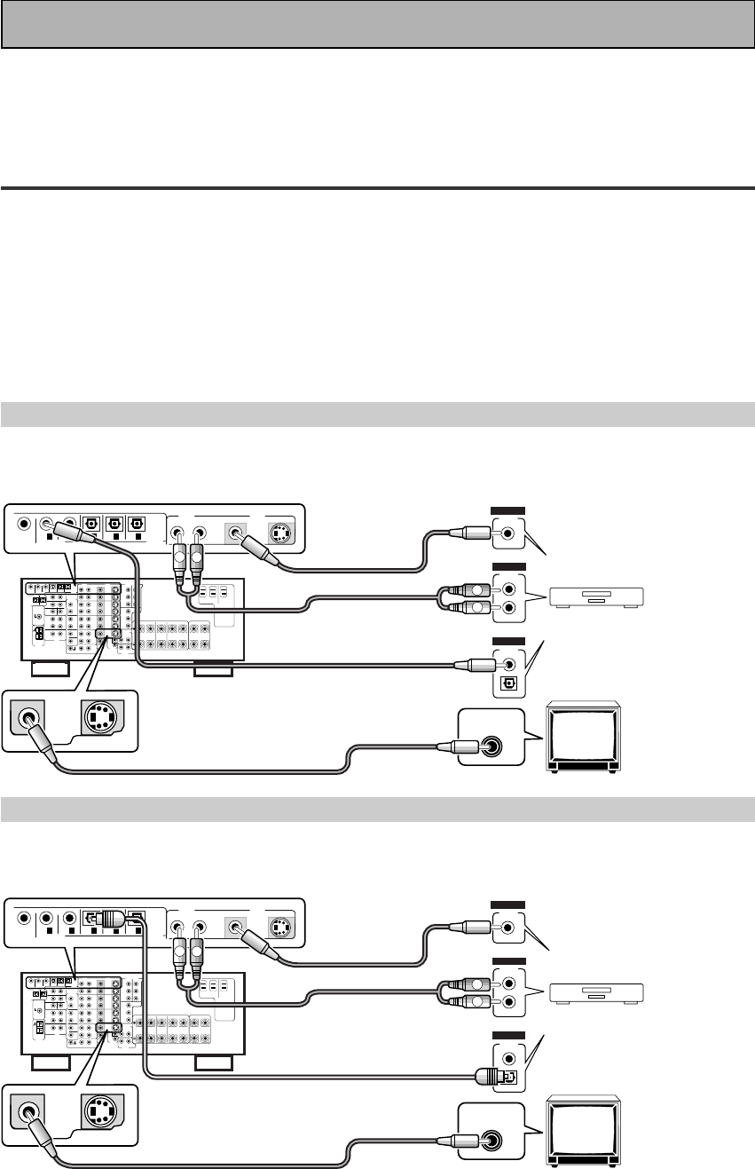
1 Hooking Up Your DVD Player & TV
In order to use Dolby Digital/DTS soundtracks which are at the heart of home theater you need to hook up your
DVD player with digital audio connections. You can do this by either a coaxial or an optical connection, you don’t
need to do both. The quality of these two types of connections is the same but since some digital components
only have one type of digital terminal you need to figure out which yours has and hook it up to the appropriate
terminal on the receiver. In order to do this you will need the proper cable. For coaxial connections you can use a
regular RCA stereo cord or the specially-made coaxial cords, they have the same type of plugs. For optical
connections you will need a special optical cord which you can buy at your local stereo store. Also hook up the
video connection of your DVD player, the analog audio (for recording the audio on DVDs, use regular RCA stereo
cords), and your TV (it's easiest to use a regular composite RCA video cords) as shown below. It is important
that you hook up your TV (or monitor) in order to see a video image as well as the on screen displays (OSDs)
shown by this receiver (for more on p.16-17). We also recommend hooking up your all your digital components
to analog audio jacks. For this you can use regular RCA stereo cords.
Coaxial Digital Connection
If your DVD player has a coaxial terminal (not a PCM-only output) for the audio out hook it up using this terminal.
Follow the diagram below. This is the best scenario, as you will be able to follow the default settings of this
receiver and won't need to assign the digital inputs.
Optical Digital Connection
If your DVD player has an optical terminal (not a PCM-only output) for the audio out you can hook it up using this
following the diagram below. You will need to assign the digital input (tell the receiver which input you put your
DVD digital audio into). See page VI for this.
(not a PCM-only output)
(not a PCM-only output)
DVD player
OUTPUT
DIGITAL
STEREO
R
L
ANALOG
VIDEO
OUT
VIDEO
VIDEO INPUT
DVD /
LD
IN
S VIDEOVIDEO VIDEOAUDIO
IN
IN
5
IN
4
IN
3
2
RF IN
(AC-3) IN
2
IN
1
MONITOR
OUT1
PCM/
2
/
DTS/
MPEG
DIGITAL
L
R
R
L
RCA video cord
RCA video cord
RCA stereo cord
coaxial cord
DVD player
OUTPUT
DIGITAL
STEREO
R
L
ANALOG
VIDEO
OUT
VIDEO
VIDEO INPUT
DVD /
LD
IN
S VIDEOVIDEO VIDEOAUDIO
IN
IN
5
IN
4
IN
3
2
RF IN
(AC-3) IN
2
IN
1
MONITOR
OUT1
L
R
R
L
RCA video cord
RCA video cord
RCA stereo cord
optical cord
PCM/
2
/
DTS/
MPEG
DIGITAL
IV
En
Quick Start Guide
22
22
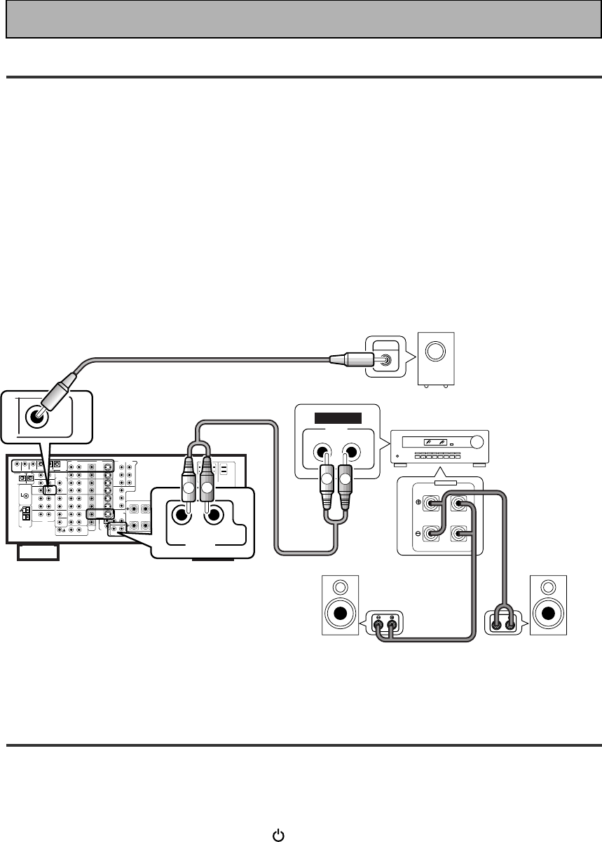
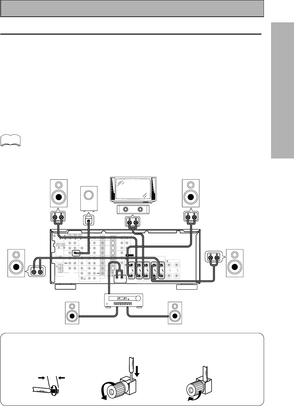
2 Speaker Connections
Home theater is designed to be setup with five, or seven speakers (front left & right; center; surround left &
right; and, optimally, surround back left & right) and a subwoofer but you can use this receiver with fewer
speakers. Hook up the speakers you have to the A speaker terminals on the back of the receiver. If you only
have two speakers hook them up as “FRONT“. If you have three hook up the single speaker as “CENTER“.
Follow the diagram on p.19 in order to hook up all your speakers. A center speaker is very important for
watching films because the dialog comes from the center speaker in digital soundtracks. If you do not have a
CENTER speaker you must tell the receiver the CENTER channel is OFF or when you listen to digital
soundtracks you won't hear any dialog. Use the instructions on page 33-34 in order to do this.
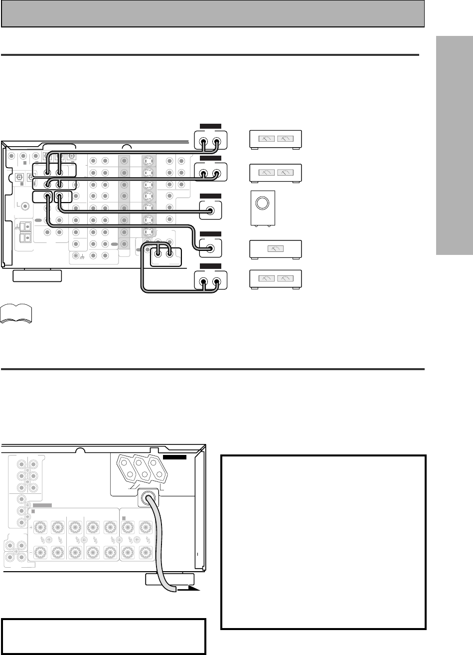
Follow the diagram below to hook up an additional amplifier in order to use surround back speakers. These
speakers are important to hear all the sound channels on new, eight channel home theater DVDs. The diagram
below also explains how to hook up a subwoofer which provides realistic bass sounds.
Make sure you connect the speaker on the right to the right terminal and the speaker on the left to the left
terminal. Also make sure the positive and negative (+/–) terminals on the amplifier match those on the speakers.
33
33
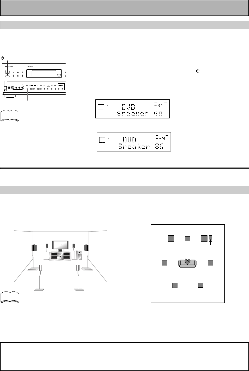
3 Setting up the Remote Control & Unit
1 Put the batteries in the remote control.
2 Plug the main unit into a wall outlet.
3 Press _ ON/ — OFF button and the STANDBY/ON button on the receiver to
put the receiver in ON mode.
RL (Single)
SURROUND
BACK
PRE OUT
SUB
WOOFER
Surround back
speaker (Right)
Surround back
speaker (Left)
INPUT Powered
subwoofer
Additional Amplifier (See p.21)
INPUT L
L
R
R
ANALOG
FRONT
SPEAKERS
L
LR
R
RCA stereo cord
RCA audio cord
V
En
Quick Start Guide
44
44
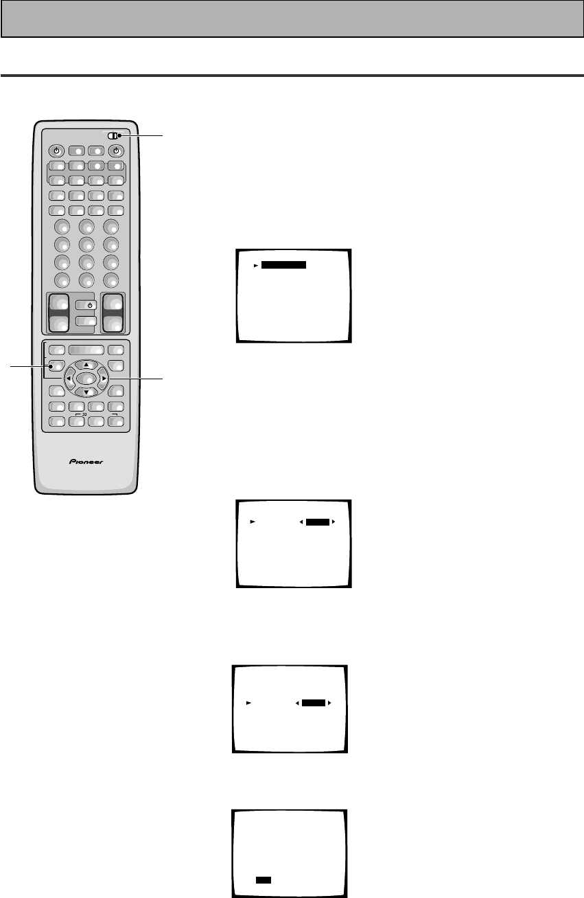
4 Digital Input Assignment
This is only necessary if you did not hook up your DVD to DIGITAL IN 1, as in the first diagram on p.III
1 Set the remote control slide switch to SETUP.
Also make sure your TV is on and set to the receiver.
• When you're done setting up the receiver, remember to set
the slide switch back to USE.
2 Press the SYSTEM SETUP button.
You should see the following display on your TV.
System Setup
[Digital-In Select]
[Speaker Setting]
[Channel Delay]
[Channel Level]
[Crossover Network]
[Bass Peak Level]
[D-Range Control]
[Multi Channel In]
• You can escape from this screen at any time by pressing the
SYSTEM SETUP button again. None of the settings you
made will be entered in this case.
• If don't enter any settings the receiver will revert back to its
previous state after three minutes.
3 Digital in Select should be selected (if it isn't use
the 5¥∞ buttons to select it). Press ENTER.
You should see the following display on your TV.
Digital-In Select
Digital-1
Digital-2
Digital-3
Digital-4
Digital-5
AC-3 RF
[EXIT] L
[DVD/LD]
[ CD ]
[ MD ]
[TV/SAT ]
[ VCR1 ]
[DVD/LD]
4 Choose the Digital-3 you hooked up your DVD
player to and assign "DVD/LD" to it.
Use the 2 or 3 buttons to choose the DVD/LD setting.
5 Select EXIT with 5¥∞ buttons and press ENTER
to return to the SYSTEM SETUP MENU.
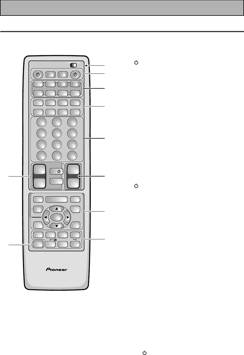
AV PRE-PROGRAMMED AND LEARNING
REMOTE CONTROL UNIT
3-5
1
2
/DTS/MPEG
S0URCE
DVD/LD TV/SAT VCR1 VCR2
CD
TV VOL
TV FUNC
MENU
ENTER
STEREO/
DIRECT
DSP
THXLIGHT
MUTE
TV
VOLUME
MD/
TAPE1 TUNER TVCONT
RECEIVER
USE SETUP
MULTI
OPERATION
CLASS MPX
DIRECT ACCESS
CHANNEL
STATION
TUNING
DISPLAY
RF ATT
TV CONTROL
FUNCTION
REMOTE SETUP
SYSTEM SETUP
INPUT
ATT
ADVANCED
MIDNIGHT
MULTI CH
INPUT
STANDARD
DIGITAL
NR
EFFECT/
CH SEL
SIGNAL
SELECT
BAND
SYSTEM
OFF
123
456
789
0
DISC
Î
¶ 873
1¡4¢
+
-
+
-
+
-
MULTI CONTROL
++
––
+
–
+10
Digital-In Select
Digital-1
Digital-2
Digital-3
Digital-4
Digital-5
AC-3 RF
[EXIT] L
[DVD/LD]
[ CD ]
[DVD/LD]
[TV/SAT ]
[ VCR1 ]
[DVD/LD]
Digital-In Select
Digital-1
Digital-2
Digital-3
Digital-4
Digital-5
AC-3 RF
[EXIT] L
[ OFF ]
[ CD ]
[DVD/LD]
[TV/SAT ]
[ VCR1 ]
[DVD/LD]
VI
En
Quick Start Guide
66
66
6 For Better Surround Sound
1 Go through the entire "system setup" procedures as outlined on pages 12-21
of this instruction manual.
If you don't hook up any other components with digital audio or do so following the default settings of
the receiver (see page 14) you won't have to assign any more digital inputs, but many other adjust-
ments will improve the sound tremendously.
2 Experiment with the different sound settings offered with the 2/DTS/MPEG
and DSP buttons.
For more information see pages 42-46.
3 As mentioned above you should go through the "speaker setup" instructions
on pages 29-41 to set up your speakers properly. If you don't do this you, at
least, need to make sure the CENTER channel is turned off if you don't have a
center speaker. Use the instructions on pages 30-34.
Speaker Setting
[FREE] [THX]
[LARGE]
[LARGE]
[LARGE]
[LARGEx2]
[ YES ]
Front L
Center
Surround
SurrBack
Subwoofer
[EXIT]
55
55
5 Playing a DVD with Surround Sound
AV PRE-PROGRAMMED AND LEARNING
REMOTE CONTROL UNIT
1
2
3
2
/DTS/MPEG
S0URCE
DVD/LD TV/SAT VCR1 VCR2
CD
TV VOL
TV FUNC
MENU
ENTER
STEREO/
DIRECT
DSP
THXLIGHT
MUTE
TV
VOLUME
MD/
TAPE1 TUNER TVCONT
RECEIVER
USE SETUP
MULTI
OPERATION
CLASS MPX
DIRECT ACCESS
CHANNEL
STATION
TUNING
DISPLAY
RF ATT
TV CONTROL
FUNCTION
REMOTE SETUP
SYSTEM SETUP
INPUT
ATT
ADVANCED
MIDNIGHT
MULTI CH
INPUT
STANDARD
DIGITAL
NR
EFFECT/
CH SEL
SIGNAL
SELECT
BAND
SYSTEM
OFF
123
456
789
0
DISC
Î
¶ 873
1¡4¢
+
-
+
-
+
-
MULTI CONTROL
++
––
+
–
+10
Set the remote control slide switch to USE.
1 Turn on the receiver, your TV, and the DVD player.
2 Press the DVD/LD button on the remote control.
You should see "DVD/LD" in the display on the receiver.
3 Press the STANDARD button for the basic
surround sound setting.
4 Play a DVD.

7
En
PREPARATION
Table of Contents
Before You Start ................................... 9
Checking the Supplied Accessories .......................... 9
How to Use This Manual ............................................ 9
Preparing the Remote Control ................................... 9
Loading the batteries .............................................. 9
Operating range of remote control unit .............. 10
Operating other PIONEER components .............. 10
Installing the Receiver .............................................. 11
Ventilation ............................................................. 11
Opening the Front Panel .......................................... 11
Connecting Your Equipment ............. 12
Audio Components ................................................... 12
Cassette deck placement ...................................... 12
Digital Connections .................................................. 13
Example Connection for a DVD/LD or LD player .... 14
Digital Input Assignment ..................................... 14
Video Components ................................................... 15
Satellite TV Components ......................................... 16
TV ............................................................................... 17
Multi Channel Input (External Decoder) ................. 17
Connecting the Radio Antennas .............................. 18
Using external antennas ...................................... 18
Speakers .................................................................... 19
Speaker impedance .............................................. 20
Placing Your Speakers .............................................. 20
Speaker placement ............................................... 20
Connecting Additional Amplifiers ........................... 21
Plugging In (Except for the U.K. model) ................. 21
Displays & Controls ........................... 22
Display ....................................................................... 22
Remote Control ......................................................... 24
Front Panel ................................................................ 26
Initial Set Up ....................................... 29
On Screen Display .................................................... 29
Switching video system between
PAL and NTSC .................................................. 29
Setting Up for Surround Sound .............................. 30
Digital-In Select ..................................................... 32
Speaker Setting ..................................................... 33
Channel Delay ....................................................... 35
Channel Level ........................................................ 36
Crossover Network ............................................... 38
Bass Peak Level ..................................................... 39
Dynamic Range Control ....................................... 40
Multi Channel In Setting ...................................... 41
Multi Channel In Setting Using the Main Unit ... 41
Basic Playback .................................... 42
Sound Modes ............................................................ 42
Selecting a Sound Mode .......................................... 45
Playing Sources with Dolby Digital,
DTS or MPEG .......................................................... 46
Playing Stereo Sources ............................................ 47
Switching Analog and Digital Signal Input ............ 48
Reducing Noise During Playback ............................ 49
Listening in Midnight Mode ..................................... 50
Using the Loudness Mode ....................................... 50
Adjusting Bass and Treble ....................................... 51
MULTI CHANNEL IN Playback ................................. 52
96kHz 24bit Performance ......................................... 52
Direct Playback .......................................................... 53
Adjusting the Brightness of the Display ................. 53
DUAL MONO Setting ................................................ 54
Using the Tuner .................................. 55
Automatic and Manual Tuning ................................ 55
MPX mode ............................................................. 55
RF ATT mode ......................................................... 55
Direct Access Tuning ................................................ 56
Memorizing Frequently Used Stations ................... 57
Recalling Memorized Stations ................................. 58
Using the remote control ..................................... 58
Using the front panel ............................................ 58
Memorizing a broadcast station name
(Manual Station Name Memory) ..................... 59
To erase and change the memorized
station name ..................................................... 59
An Introduction to RDS & EON ................................ 60
Basics of EON ........................................................ 61
The receiver’s internal Program
Identification function ...................................... 61
RDS (Radio Data System) Broadcast Reception .... 62
Displaying RDS data ............................................. 62
Searching for a program by
program type (PTY) .......................................... 63
Using EON search ................................................. 64
Remote Control of Other Components ...
65
Setting Up the Remote Control to Control Other
Components .............................................................. 65
Recalling Preset Codes ......................................... 65
Learning Commands from Other
Remote Controls ............................................... 67
Using the Remote Control with Other
Components ............................................................ 69
Using Other Functions....................... 76
Recording from Audio Components ....................... 76
Record monitor (TAPE 2 MONITOR) ................... 76
Recording from Digital Audio Components ........... 77
Recording from Video Components ....................... 77
Multi Operations ....................................................... 78
Performing Multi Operations ............................... 79
System Off ................................................................. 80
Using the System Off Button ............................... 81
Setting Up the Direct Function ................................ 81
Remote Back Light .................................................... 82
Resetting the Remote Control ................................. 82
Erasing Multi Operations ..................................... 82
Erasing Learned Remote Control Commands ........ 83
Erasing All Learned Commands and
Preset Codes ........................................................... 83
Video Select .............................................................. 84
Techno Tidbits & Problem-solving.... 85
Preset Code List ........................................................ 88
Troubleshooting ........................................................ 92
Specifications ............................................................ 95
OPERATION
SET
UP
8
En
Features
Multi Channel Stereophonic Concept
The VSX-909RDS/909RDS-G receiver is constructed with Pioneer’s industry-leading multi channel stereophonic
concept. This well-developed approach to receiver circuitry takes the high level base technology that, up until
now, has been only used for stereo equipment and applies it to multi-channel audio-visual receivers. The result
is that the product, in addition to being expertly built, and gives you optimal sound reproduction of DVDs, other
multi channel sources and stereo sources as well. This receiver is designed capture to a true reproduction of the
intentions of a filmmaker or music producer at the time they were mastering the soundtrack in the studio. It
incorporates 5 independent 110 watt built in power amplifiers, with high-performance Hex power Direct Power
MOS FET output transistors. This construction provides improved linearity and accurate representation of each
channel for true high fidelity reproduction from even the most demanding Dolby Digital and DTS program
sources. In addition, the amplifier uses Direct Construction to give the purest sound available. All these
elements consolidated in one receiver afford the listener a new surround sound experience in his or her home.
Universal Player Compatibility
This receiver incorporates the latest technology and is able to handle cutting edge audio formats, like DVD
Audio, which are just hitting the market. Its high compatibility offers a variety of inputs to decode all types of
sources at the highest possible quality. The receiver’s multi channel in connections lets you hook up eight
discrete channels of audio. It also has multi channel direct inputs and the ability to decode the cutting edge
formats.
Decoding of Next Generation Digital Source Film Formats
Built into this receiver is the latest in film sound format technology. This technology includes the recent THX
SURROUND EX and HOME THX CINEMA surround modes which employ special processing to allow you to
enjoy movie soundtracks with the same level of power and realism you experience in well-designed movie
theaters. The THX SURROUND EX mode has been especially designed to incorporate surround back channels
that some new source material uses. This receiver has the ability to decode Dolby Digital, Dolby Pro Logic,
MPEG and DTS (Digital Theater Systems) sources, which are the standards of home theater today. It also offers
component video terminals for the sharpest video transmission available to the consumer.
Advanced Theater Modes & DSP Surround Modes
Advanced Theater modes enhance the sound of either film or music so a more dramatic effect can be achieved.
The four modes are each designed to accentuate specific sound qualities, giving the listener a wide range of
possibilities. DSP (Digital Signal Processing) surround modes give you the capability of transforming your living
room into seven different sonic environments when listening to music.
RDS (Radio Data System)
With the RDS system, FM station can send additional signals with their regular program signals. For example,
the stations send their station names, and information about the type of programs they broadcast, such as
news, sport or music. This unit receives three types of RDS signals: RT, PS, and PTY.
The Energy-saving Design
This unit is designed to use less than 1 W of energy when the receiver is in standby mode.
“DTS”, "ES" and “DTS Digital Surround” are
trademarks of Digital Theater Systems, Inc.
Manufactured under licence from Digital Theater
Systems, Inc.
Manufactured under license from Dolby Laboratories.
“Dolby”, “AC-3”, “Pro Logic”, and double-D symbol
are trademarks of Dolby Laboratories. Confidential
unpublished works. © 1992 - 1997 Dolby Laboratories.
All rights reserved.
Manufactured under license from Lucasfilm Ltd. U.S.
patent numbers 5,043,970; 5,189,703; and/or
5,222,059. European patent number 0323830. Other
U.S. and foreign patents pending. Lucasfilm and THX
are registered trademarks of Lucasfilm Ltd. Surround
EX is a trademark of Dolby Labs. Used under
authorization.
The MPEG logo is a registered trademark of Royal
Philips Electronics.
9
En
PREPARATION
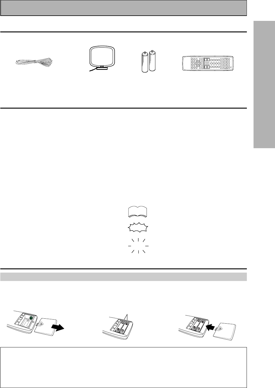
Checking the Supplied Accessories
Please check that you have received all of the following supplied accessories.
How to Use This Manual
This manual is for the VSX-909RDS/909RDS-G Audio/
Video Multi-Channel Receiver.
This manual is divided into three main sections which
will tell you how to setup and use the unit :
PREPARATION
First carry out the tasks below in this “Before You
Start“ section to prepare the remote control, then
connect the receiver to your other components as
described in “Connecting Your Equipment“ (p.12).
Take special care to connect your digital equipment
like DVDs and LDs properly to be able to take
advantage of the receiver’s surround sound systems
(p.13-14). To learn about a specific button, control, or
indicator, see “Displays & Controls“ starting on p.22.
SET UP
Performing the tasks in “Initial Set Up“ (from p.29) is
essential to get proper surround sound.
“AA” IEC LR6
batteries x 2
FM wire antenna AM loop antenna
123
\\
Remote control unit
Before You Start
memo
OPERATION
To play some music or soundtrack refer to “Basic
Playback“ on p.42. “Using the Tuner“ (p.55) explains
how to use the radio of this unit. Doing the operations
in “Remote Control of Other Components“ (p.65) is
highly recommended so you can use this unit’s
remote control for all your components. “Using Other
Functions“ (p.76) explain the other possibilities of the
receiver.
“Techno Tidbits & Problem-solving“ (p.85) provide
detailed technical information and a troubleshooting
guide.
The following marks and symbols are used throughout
the manual:
Provides additional information,
precautions, and advice.
Indicates a blinking button, indicator, or
display.
Indicates a steadily lit button, indicator, or
display.
• Operating Instructions
"AA" IEC LR6
batteries x 2
Preparing the Remote Control
Loading the batteries
Load the batteries into the remote control as shown below. Please use alkaline batteries. When you notice a
decrease in the operating range of the remote control, replace all batteries with new ones.
CAUTION!
Incorrect use of batteries may result in such hazards as leakage and bursting. Observe the following precautions.
• Never use new and old batteries together.
• Insert the plus and minus sides of the batteries properly according to the marks in the battery case.
• Batteries with the same shape may have different voltages. Do not use different batteries together.
• When disposing of used batteries, please comply with governmental regulations or environmental public institution’s
rules that apply in your country or area.
10
En
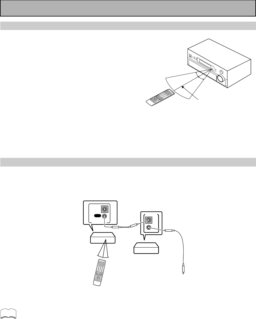
Operating range of remote control unit
The area in which you can use the remote control to operate
the VSX-909RDS/909RDS-G is fairly large. To use, point the
remote control toward the remote sensor on the front panel of
this unit while within the range shown right.
Remote control may not function properly if:
• There are obstacles between the remote control and the
remote sensor.
• Direct sunlight or fluorescent light is shining onto the
remote sensor.
• The receiver located near a device emitting infrared rays.
• Operated simultaneously with another remote control which
uses infrared rays.
30°
30°
7m
Before You Start
memo
OUT
IN
CONTROL
OUT
IN
CONTROL
PIONEER component
bearing the Î mark.
Remote Control
To CONTROL IN
terminal of another
PIONEER component
bearing the Î mark.
Receiver
• You can also control PIONEER components (and those made by other manufacturers) by pointing the
receiver’s remote control directly at the respective components. This type of operation does not require
control cords. All you have to do is recall the appropriate preset code (refer to “Recalling preset
codes” on page 65).
• If you use a remote control hooked up via the CONTROL IN jack with a control cord, you won't be able
to use this unit's remote control.
Operating other PIONEER components
Connecting an optional control cord allows you to operate other PIONEER components simply by pointing the
receiver’s remote control at the remote sensor on the front panel of the receiver. The receiver then sends the
remote control signals to the other components via the CONTROL OUT terminal.
11
En
PREPARATION
Before You Start
Installing the Receiver
Ventilation
• When installing this unit, make sure to leave space around the unit for ventilation to improve heat radiation (at
least 60 cm at the top, 10 cm at the rear, and 30 cm at each side). If not enough space is provided between
the unit and walls or other equipment, heat will build up inside, interfering with performance or causing
malfunctions.
• Do not place on a thick carpet, bed, sofa or fabric having a thick pile. Do not cover with fabric or other
covering.
Anything that blocks ventilation will cause the internal temperature to rise, which may lead to breakdown or
fire hazard.
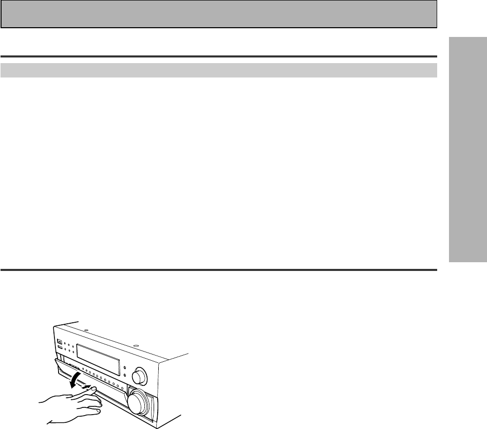
Opening the Front Panel
To open the front panel push gently on the lower third of the panel with your finger.
12
En
Connecting Your Equipment
Cassette deck placement
Depending on where the cassette deck is placed,
noise may occur during playback of your cassette
deck which is caused by leakage flux from the
transformer in the receiver. If you experience noise,
move the cassette deck farther away from the
receiver.
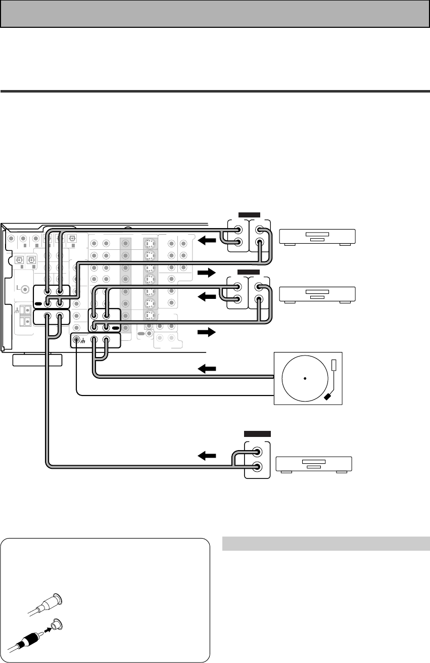
7 Audio cords
Use audio cords (not supplied) to connect the
audio components.
Connect red plugs to R (right)
and white plugs to L (left).
Be sure to insert completely.
L
R
Before making or changing the connections, switch off the power and
disconnect the power cord from the AC outlet.
Audio Components
To begin set up connect your audio components to the jacks as shown below. These are all analog connections
and your analog audio components (turntable, cassette deck) use these jacks. Remember that for components
you want to record with you need to hook up four plugs (a set of stereo ins and a set of stereo outs), but for
components that only play (like a turntable) you only need to hook up one set of stereo plugs (two plugs). To use
DTS or Dolby Digital surround sound features you must hook up your digital components to the digital inputs
(see p.13). We also recommend hooking up your digital components to analog audio jacks. If you want to record
to/from digital components (like an MD) to/from analog components you must hook up your digital equipment
with these analog connections. See p.13 & 14 for more on digital connections.
*The arrows indicate the direction of the audio signal.
If your turntable
has a ground
wire, connect it
to the SIGNAL
GND terminal.
CD
IN
SURR-
OUND
SUB
WOOFER
CENTER
FRONT
MULTI CH IN
SURR-
OUND
RL
RL
RL
RL
RL (Single)
R
R
L
L
R
L
RL
FRONT
AUDIO
SUB
WOOFER
PRE OUT
CENTER
COMPONENT VIDEO
DVD/LD
IN TV/SAT
IN
Y
P
B
P
R
MONITOR
OUT
MONITOR
OUT 1
MONITOR
OUT 2
P
B
P
R
Y
MULTI CH IN
SURROUND
BACK
SURROUND
BACK
PRE OUT
DVD /
LD
IN
S VIDEOVIDEO VIDEOAUDIO
IN
TV /
SAT
IN
IN
OUT
IN
VCR1 /
DVR
OUT
IN
OUT
IN
VCR2
OUT
IN
CONTROL
IN
OUT
MD /
TAPE1/
CD-R
PLAY
REC
TAPE2
MONITOR
PLAY
REC
PCM/
2
/
DTS/
MPEG
DIGITAL
IN
5
IN
4
IN
3
2
RF IN
(AC-3) IN
2
IN
1
IN
PHONO
FM UNBAL
75‰
FM
ANTENNA
AM LOOP
ANTENNA
OUTOUT
21
CD player
Turntable
OUTPUT
L
R
ANALOG
Recorder 1(MD/Tape)
OUTPUT
(PLAY)
L
R
INPUT
(REC)
L
R
ANALOG
Recorder 2(MD/Tape)
OUTPUT
(PLAY)
L
R
INPUT
(REC)
L
R
ANALOG
Please don't hook up any other component to the phono jacks other than a turntable. It could damage the
equipment. If your turntable has a built-in amplifier please hook it up to an input other than PHONO.
13
En
PREPARATION
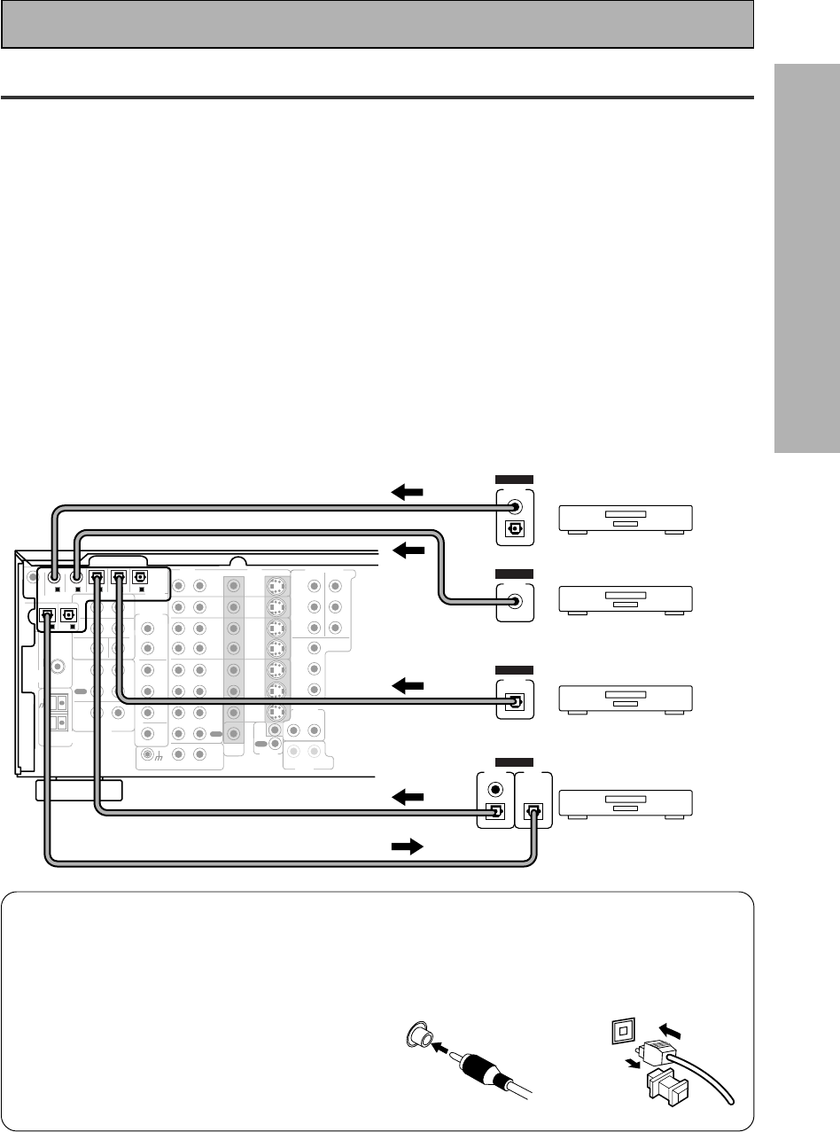
Digital Connections
In order to use Dolby Digital/DTS soundtracks which are at the heart of home theater you need to make digital
audio connections. You can do this by either a coaxial or an optical connection (you don’t need to do both). The
quality of these two types of connections is the same but since some digital components only have one type of
digital terminal, it is a matter of matching like with like (for example, the coaxial out from the component to
coaxial in on the receiver). The receiver has two coaxial and three optical inputs for a total of five digital inputs. A
DVD/LD player or LD player should be connected to a digital jack and the special 2 RF jack (if the LD has one)
as well as a pair of analog jacks (see the next page). If possible, hook up your digital equipment in accordance
with this receiver's default settings. See “Digital Input Assignment“ below left, in order to do this.We also
recommend hooking up your digital components to analog audio jacks in order to make recording from some
digital sources which may be copy protected.
Connect your digital components as shown below.
There are two optical digital out jacks (the MD recorder is connected to one in the diagram below). If you
connect this to the optical input on a digital recorder (currently these include MD, DAT and CD-R) you can make
direct digital recordings with this unit.
Before making or changing the connections, switch off the power and disconnect the power cord from the AC
outlet.
*The arrows indicate the direction of the audio signal.
CD
IN
SURR-
OUND
SUB
WOOFER
CENTER
FRONT
MULTI CH IN
SURR-
OUND
RL
RL
RL
RL
RL (Single)
R
R
L
L
R
L
RL
FRONT
AUDIO
SUB
WOOFER
PRE OUT
CENTER
COMPONENT VIDEO
DVD/LD
IN TV/SAT
IN
Y
P
B
P
R
MONITOR
OUT
MONITOR
OUT 1
MONITOR
OUT 2
P
B
P
R
Y
MULTI CH IN
SURROUND
BACK
SURROUND
BACK
PRE OUT
DVD /
LD
IN
S VIDEOVIDEO VIDEOAUDIO
IN
TV /
SAT
IN
IN
OUT
IN
VCR1 /
DVR
OUT
IN
OUT
IN
VCR2
OUT
IN
CONTROL
IN
OUT
MD /
TAPE1/
CD-R
PLAY
REC
TAPE2
MONITOR
PLAY
REC
PCM/
2
/
DTS/
MPEG
DIGITAL
IN
5
IN
4
IN
3
2
RF IN
(AC-3) IN
2
IN
1
IN
PHONO
FM UNBAL
75‰
FM
ANTENNA
AM LOOP
ANTENNA
OUTOUT
21
MD recorder
OUTPUT
(PLAY) INPUT
(REC)
DIGITAL
TV tuner
DVD player
OUTPUT
DIGITAL
OUTPUT
DIGITAL
CD player
OUTPUT
DIGITAL
Connecting Your Equipment
7Coaxial cords/Optical cables
Commercially available digital audio coaxial
cords (standard video cords can also be
used) or optical cables (not supplied) are
used to connect digital components to this
receiver.
When you use optical digital input or output
terminals, pull off the caps and insert the
plugs. Be sure to insert completely.
Coaxial cord
(or standard video cord)
Optical cable
(not a PCM-only output)
14
En
memo
CD
IN
SURR-
OUND
SUB
WOOFER
CENTER
FRONT
MULTI CH IN
SURR-
OUND
RL
RL
RL
RL
RL (Single)
R
R
L
L
R
L
RL
FRONT
AUDIO
SUB
WOOFER
PRE OUT
CENTER
COMPONENT VIDEO
DVD/LD
IN TV/SAT
IN
Y
Y
P
B
P
R
MONITOR
OUT
MONITOR
OUT 1
MONITOR
OUT 2
P
B
P
R
Y
MULTI CH IN
SURROUND
BACK
SURROUND
BACK
PRE OUT
DVD /
LD
IN
S VIDEOVIDEO VIDEOAUDIO
IN
TV /
SAT
IN
IN
OUT
IN
VCR1 /
DVR
OUT
IN
OUT
IN
VCR2
OUT
IN
CONTROL
IN
OUT
MD /
TAPE1/
CD-R
PLAY
REC
TAPE2
MONITOR
PLAY
REC
PCM/
2
/
DTS/
MPEG
DIGITAL
IN
5
IN
4
IN
3
2
RF IN
(AC-3) IN
2
IN
1
IN
PHONO
FM UNBAL
75‰
FM
ANTENNA
AM LOOP
ANTENNA
OUTOUT
21
DVD/LD player
or LD player
1
23
DIGITAL OUT
(AC-3)(LD)
RF OUT
2
COMPO-
NENT VIDEO
OUT
VIDEO
S-VIDEO
P
B
P
R
STEREO
L
R
ANALOG
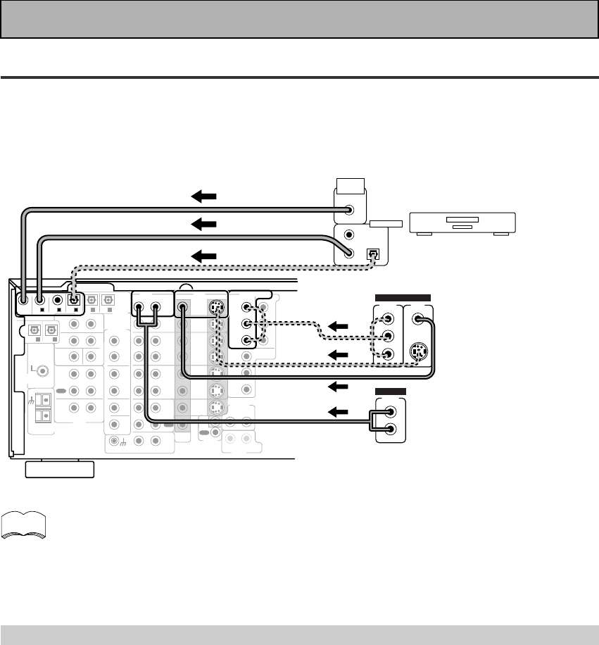
Connecting Your Equipment
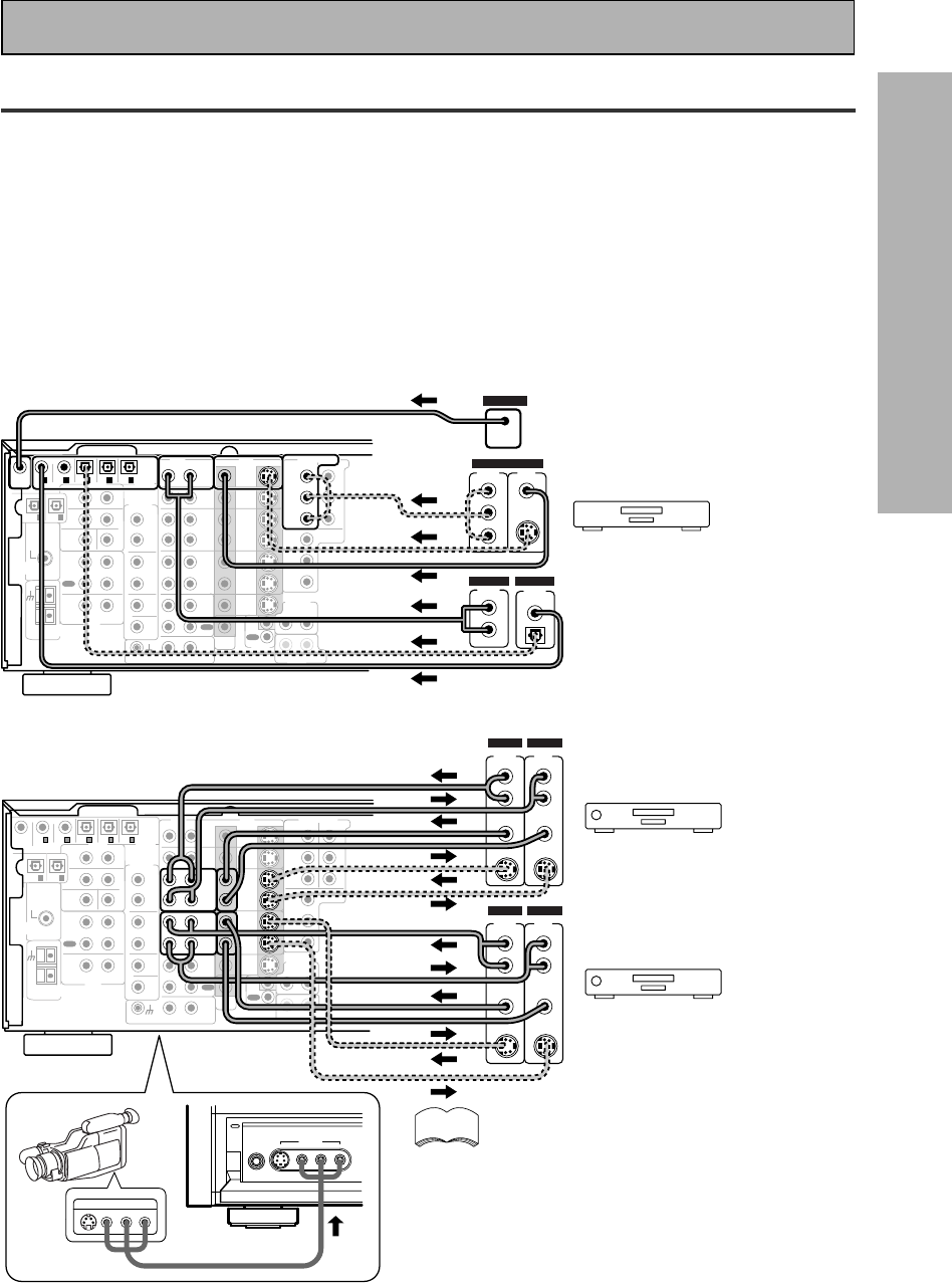
Example Connection for a DVD/LD or LD player
Make sure you connect your DVD/LD or LD players using both the 2 RF jack and either a coaxial or optical (you
don't need to do both of these) digital connections. If your player has an 2 RF output this will ensure you can
use all LDs (see p.15). We also recommend hooking up your digital components to analog audio jacks.
Before making or changing the connections, switch off the power and disconnect the power cord from the AC
outlet.
*The arrows indicate the direction of the audio signal.
Be sure to make either a digital coaxial or digital optical connection (pictured as DIGITAL jack 1
or DIGITAL jack 3 in this diagram) as well, but you DON'T need to make both.
Also, be sure to assign the jacks to the proper component(s) with the
Digital-In Select
procedure
(see p.32) if necessary. See the explanation below for details.
(not a PCM-only output)
Digital Input Assignment
Unlike analog connections, the jacks for digital connections are not dedicated to one type of component, they
can be used freely. Thus you must tell the receiver what digital component in which jack so your components
will be in sync with the the names on the remote control buttons and the like. To avoid having to assign the
digital inputs you can hook up your equipment in accordance with the receiver's default settings.
The default settings are:
DIGITAL IN 1: DVD/LD
DIGITAL IN 2: CD
DIGITAL IN 3: MD
DIGITAL IN 4: TV/SAT
DIGITAL IN 5: VCR1
AC-3 RF: DVD/LD
You will notice that Digital IN 1, for example, is a coaxial jack. If your DVD/LD player only has an optical out jack on
it then you won't be able to hook up your components in accordance with the VSX-909RDS/909RDS-G default
setting. In this case you will need to assign the digital inputs. See
Digital-In Select
on p.32 in order to do this.
15
En
PREPARATION
CD
IN
SURR-
OUND
SUB
WOOFER
CENTER
FRONT
MULTI CH IN
SURR-
OUND
RL
RL
RL
RL
RL (Single)
R
R
L
L
R
L
RL
FRONT
AUDIO
PRE OUT
CENTER
COMPONENT VIDEO
DVD/LD
IN TV/SAT
IN
Y
P
B
P
R
MONITOR
OUT
MONITOR
OUT 1
MONITOR
OUT 2
P
B
P
R
Y
MULTI CH IN
SURROUND
BACK
SURROUND
BACK
PRE OUT
DVD /
LD
IN
S VIDEOVIDEO VIDEOAUDIO
IN
TV /
SAT
IN
IN
OUT
IN
VCR1 /
DVR
OUT
IN
OUT
IN
VCR2
OUT
IN
CONTROL
IN
OUT
MD /
TAPE1/
CD-R
PLAY
REC
TAPE2
MONITOR
PLAY
REC
PCM/
2
/
DTS/
MPEG
DIGITAL
IN
5
IN
4
IN
3
2
RF IN
(AC-3) IN
2
IN
1
IN
PHONO
FM UNBAL
75‰
FM
ANTENNA
AM LOOP
ANTENNA
OUTOUT
21
SUB
WOOFER
DVD/LD player
COMPO-
NENT VIDEO
OUT
L
VIDEO
STEREO
L
R
DIGITAL
ANALOG
PCM/
2
/ DTS
DIGITAL
S-VIDEO
Y
P
B
P
R
RF OUT (LD)
2
RF OUT
(LD)
CD
IN
SURR-
OUND
SUB
WOOFER
CENTER
FRONT
MULTI CH IN
SURR-
OUND
RL
RL
RL
RL
RL (Single)
R
R
L
L
R
L
RL
FRONT
AUDIO
PRE OUT
CENTER
COMPONENT VIDEO
DVD/LD
IN TV/SAT
IN
Y
P
B
P
R
MONITOR
OUT
MONITOR
OUT 1
MONITOR
OUT 2
P
B
P
R
Y
MULTI CH IN
SURROUND
BACK
SURROUND
BACK
PRE OUT
DVD /
LD
IN
S VIDEOVIDEO VIDEOAUDIO
IN
TV /
SAT
IN
IN
OUT
IN
VCR1 /
DVR
OUT
IN
OUT
IN
VCR2
OUT
IN
CONTROL
IN
OUT
MD /
TAPE1/
CD-R
PLAY
REC
TAPE2
MONITOR
PLAY
REC
PCM/
2
/
DTS/
MPEG
DIGITAL
IN
5
IN
4
IN
3
2
RF IN
(AC-3) IN
2
IN
1
IN
PHONO
FM UNBAL
75‰
FM
ANTENNA
AM LOOP
ANTENNA
OUTOUT
21
SUB
WOOFER
PHONES S-VIDEO VIDEO L AUDIO R
VIDEO INPUT
LV R
VIDEO INPUT
VCR 1/DVR
VCR 2
VIDEO
S-VIDEO
VIDEO
S-VIDEO
AUDIO
(PLAY)
L
R
AUDIO
(REC)
L
R
S-VIDEO
VIDEOVIDEO
S-VIDEO
AUDIO
(PLAY)
L
R
AUDIO
(REC)
L
R
OUT IN
OUT IN
Connecting DVD/LD players
Connecting VCRs or DVRs
(LD player only)
Connecting Your Equipment
Video Components
Connect your video components to the jacks as shown below. Regarding a DVD there are two types of
connections to make. Hook up your video signal with either component video, S-video, or composite video cords
(the quality descends in this order) but remember, the video component you are watching and your TV must be
hooked up with same type of video cord or you won't be able to see the picture. For the audio signal, order to use
Dolby Digital/DTS you must hook up a digital input. It is also a good idea to hook up your DVD components with
analog audio connections as well, since some DVDs may not have a digital audio track. To cover all possible laser
discs a DVD/LD player or LD player requires an analog connection and two digital connections (a coaxial or optical
and a specialized 2 RF connection shown at the very top of the first diagram below).
Before making or changing the connections, switch off the power and disconnect the power cord from the AC
outlet.
*The arrows indicate the direction of the video signal.
(not a PCM-only output)
If you hook up your DVD/LD player
using component video
connections be sure to select
component video output on your
DVD player as well. See you DVD
manual for details.
Front video connections are accessed via the
front panel input selector as “VIDEO.“
If your video components have S-video jacks,
you could use S-video cords (not supplied) to connect
them on the back of the receiver. These jacks are
labeled by the Japanese designation
“
S2
“
on the VSX-
909RDS/909RDS-G but they are simply S-video jacks.
However, if you use S-video cords for your video hook
ups you must also hook up your TV with S-video
connections. Conversely, if you use regular composite
video cords for video hook ups, you should use them
for your TV as well.
memo
16
En
CD
IN
SURR-
OUND
SUB
WOOFER
CENTER
FRONT
MULTI CH IN
SURR-
OUND
RL
RL
RL
RL
RL (Single)
R
R
L
L
R
L
RL
FRONT
AUDIO
PRE OUT
CENTER
COMPONENT VIDEO
DVD/LD
IN TV/SAT
IN
Y
P
B
P
R
MONITOR
OUT
MONITOR
OUT 1
MONITOR
OUT 2
P
B
P
R
Y
MULTI CH IN
SURROUND
BACK
SURROUND
BACK
PRE OUT
DVD /
LD
IN
S VIDEOVIDEO VIDEOAUDIO
IN
TV /
SAT
IN
IN
OUT
IN
VCR1 /
DVR
OUT
IN
OUT
IN
VCR2
OUT
IN
CONTROL
IN
OUT
MD /
TAPE1/
CD-R
PLAY
REC
TAPE2
MONITOR
PLAY
REC
PCM/
2
/
DTS/
MPEG
DIGITAL
IN
5
IN
4
IN
3
2
RF IN
(AC-3) IN
2
IN
1
IN
PHONO
FM UNBAL
75‰
FM
ANTENNA
AM LOOP
ANTENNA
OUTOUT
21
TV/Satellite tuner
COMPO-
NENT VIDEO
OUT
L
VIDEO
STEREO
L
R
DIGITAL
ANALOG
PCM/
2
/ DTS
DIGITAL
S-VIDEO
Y
PB
PR
SUB
WOOFER
Connecting Your Equipment
7 Analog audio/video cords
Use audio/video cords (not supplied) to
connect the video components and a video
cord to connect the monitor TV.
Connect red plugs to R (right), white plugs to
L (left), and the yellow plugs to VIDEO.
Be sure to insert completely.
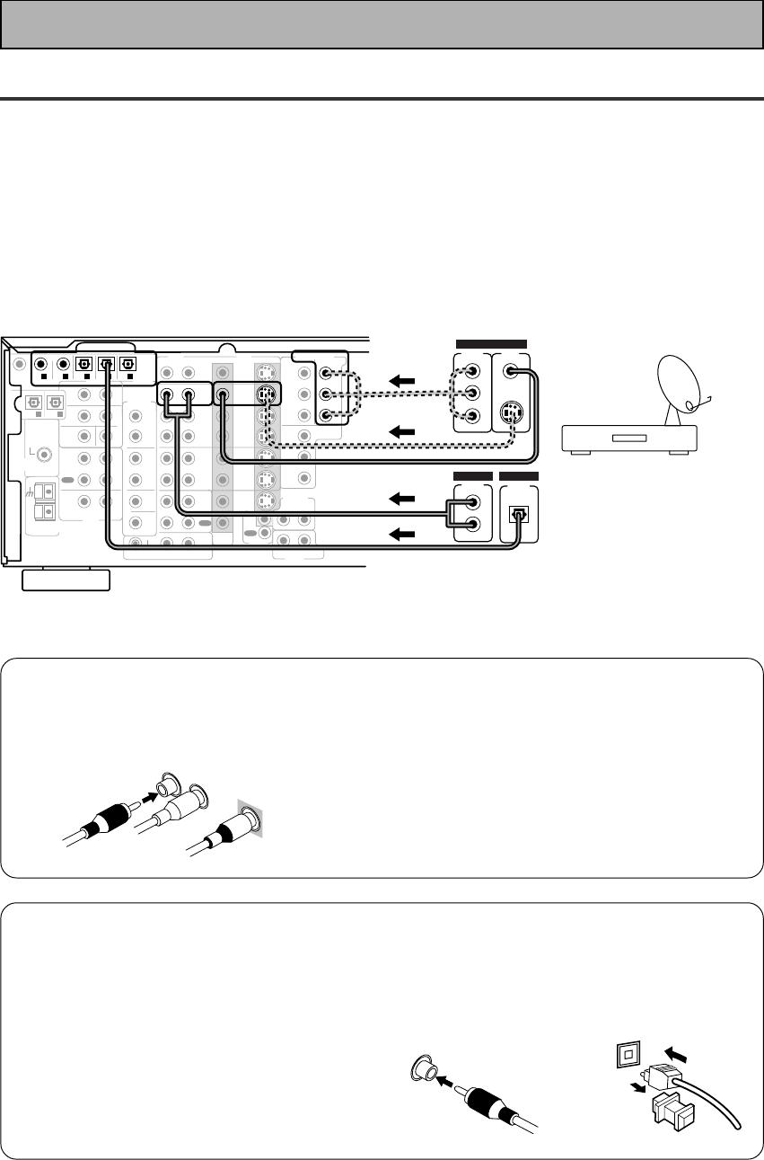
7Digital audio coaxial cords/
Optical cables
Commercially available digital audio coaxial
cords (standard video cords can also be
used) or optical cables (not supplied) are
used to connect digital components to this
receiver.
When you use optical digital input or output
terminals, pull off the caps and insert the
plugs. Be sure to insert completely.
Digital audio coaxial
cord
(or standard video
cord)
Optical cable
L
R
VIDEO
Satellite TV Components
Connect your satellite TV components to the jacks as shown below. Hook up the video signal with either
component video, S-video, or composite video cords (the quality descends in this order) but remember, the
video component you are watching and your TV must be hooked up with same type of video cord or you won't
be able to see the picture. For the audio signal, order to use digital soundtracks (sometimes broadcast over
digital satellite TV) you must hook up a digital input. Use either a coaxial or optical cables, it doesn't matter
which (you don't need to use both). It's also a good idea to hook up your audio with analog cables (see below).
This connection is called STEREO AUDIO OUT in the diagram.
Before making or changing the connections, switch off the power and disconnect the power cord from the AC
outlet.
*The arrows indicate the direction of the TV signal.
17
En
PREPARATION
CD
IN
SURR-
OUND
SUB
WOOFER
CENTER
FRONT
MULTI CH IN
SURR-
OUND
RL
RL
RL
RL
RL (Single)
R
R
L
L
R
L
RL
FRONT
AUDIO
PRE OUT
CENTER
COMPONENT VIDEO
DVD/LD
IN TV/SAT
IN
Y
P
B
P
R
MONITOR
OUT
MONITOR
OUT 1
MONITOR
OUT 2
P
B
P
R
Y
MULTI CH IN
SURROUND
BACK
SURROUND
BACK
PRE OUT
DVD /
LD
IN
S VIDEOVIDEO VIDEOAUDIO
IN
TV /
SAT
IN
IN
OUT
IN
VCR1 /
DVR
OUT
IN
OUT
IN
VCR2
OUT
IN
CONTROL
IN
OUT
MD /
TAPE1/
CD-R
PLAY
REC
TAPE2
MONITOR
PLAY
REC
PCM/
2
/
DTS/
MPEG
DIGITAL
IN
5
IN
4
IN
3
2
RF IN
(AC-3) IN
2
IN
1
IN
PHONO
FM UNBAL
75‰
FM
ANTENNA
AM LOOP
ANTENNA
OUTOUT
21
TV/monitor
COMPO-
NENT VIDEO
L
VIDEO IN
S-VIDEO
Y
P
B
P
R
SUB
WOOFER
CD
IN
SURR-
OUND
SUB
WOOFER
CENTER
FRONT
MULTI CH IN
SURR-
OUND
RL
RL
RL
RL
RL (Single)
R
R
L
L
R
L
RL
FRONT
AUDIO
PRE OUT
CENTER
COMPONENT VIDEO
DVD/LD
IN TV/SAT
IN
Y
P
B
P
R
MONITOR
OUT
MONITOR
OUT 1
MONITOR
OUT 2
P
B
P
R
Y
MULTI CH IN
SURROUND
BACK
SURROUND
BACK
PRE OUT
DVD /
LD
IN
S VIDEOVIDEO VIDEOAUDIO
IN
TV /
SAT
IN
IN
OUT
IN
VCR1 /
DVR
OUT
IN
OUT
IN
VCR2
OUT
IN
CONTROL
IN
OUT
MD /
TAPE1/
CD-R
PLAY
REC
TAPE2
MONITOR
PLAY
REC
PCM/
2
/
DTS/
MPEG
DIGITAL
IN
5
IN
4
IN
3
2
RF IN
(AC-3) IN
2
IN
1
IN
PHONO
FM UNBAL
75‰
FM
ANTENNA
AM LOOP
ANTENNA
OUTOUT
21
SUB
WOOFER
Components equipped with
7.1 (5.1) channel analog output jack
SUB
WOOFER SURR-
OUND BACK
L
R
CENTER
SURR-
OUND
L
R
FRONT
L
R
ANALOG
Connecting Your Equipment
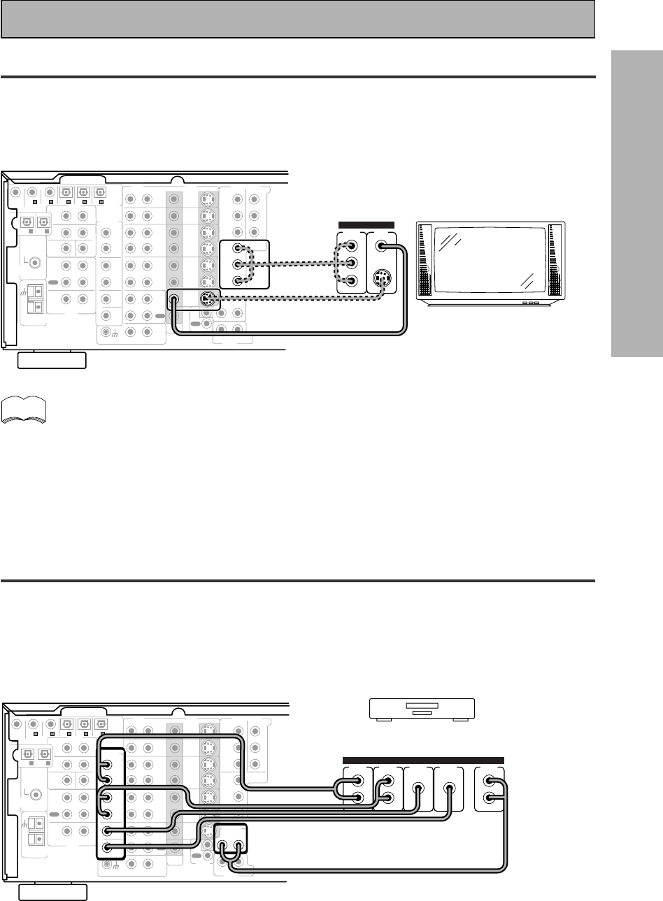
TV
Connect your TV to the jacks as shown below. Hook up the signal with either component video, S-video, or
composite video cords (the quality descends in this order) but remember, the video component you are
watching and your TV must be hooked up with same type of video cord or you won't be able to see the picture.
Before making or changing the connections, switch off the power and disconnect the power cord from the AC
outlet.
The COMPONENT VIDEO OUT jack can be used to get a TV picture but it doesn't show this
receiver's on screen display (OSD).
If you use S video cords to hook up a component the OSDs from the receiver will only be able
to be seen on the S video out terminals.
Multi Channel Input (External Decoder)
In some cases you may want to have your source material (DVD, etc) decoded externally. If you find you need a
multi channel external decoder hook one up as shown below, but for most people this component is
unnecessary (For more on this see p.52).
Before making or changing the connections, switch off the power and disconnect the power cord from
the AC outlet.
memo
18
En
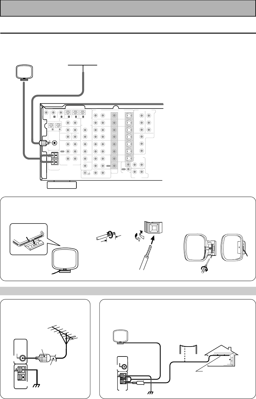
Connecting the Radio Antennas
Connect the supplied FM wire antenna and the AM loop antenna to the antenna terminals as shown below.
These antennas should provide adequate reception quality in most cases, but connecting outdoor antennas
should noticeably improve sound quality.
CD
IN
SURR-
OUND
SUB
WOOFER
CENTER
FRONT
MULTI CH IN
SURR-
OUND
RL
RL
RL
RL
RL (Single)
R
R
L
L
R
L
RL
FRONT
AUDIO
PRE OUT
CENTER
COMPONENT VIDEO
DVD/LD
IN TV/SAT
IN
Y
P
B
P
R
MONITOR
OUT
MONITOR
OUT 1
MONITOR
OUT 2
P
B
P
R
Y
MULTI CH IN
SURROUND
BACK
SURROUND
BACK
PRE OUT
DVD /
LD
IN
S VIDEOVIDEO VIDEOAUDIO
IN
TV /
SAT
IN
IN
OUT
IN
VCR1 /
DVR
OUT
IN
OUT
IN
VCR2
OUT
IN
CONTROL
IN
OUT
MD /
TAPE1/
CD-R
PLAY
REC
TAPE2
MONITOR
PLAY
REC
PCM/
2
/
DTS/
MPEG
DIGITAL
IN
5
IN
4
IN
3
2
RF IN
(AC-3) IN
2
IN
1
IN
PHONO
FM UNBAL
75‰
FM
ANTENNA
AM LOOP
ANTENNA
OUTOUT
21
SUB
WOOFER
FM wire antenna
AM loop antenna
7 AM loop antenna
1Assemble the antenna. 2Twist exposed wire strands
together and insert.
3Attach to a wall, etc. (if
desired) and face toward the
direction providing the best
reception.
Using external antennas
7 To improve FM reception
Connect an external FM antenna.
7 To improve AM reception
Connect a 5–6 meter length of vinyl-coated wire to the AM
antenna terminal in addition to the supplied AM loop antenna.
For the best possible reception, suspend horizontally outdoors.
10 mm
FM
ANTENNA
FM UNBAL
75‰
AM LOOP
ANTENNA
75 Ω coaxial
cable
PAL
connector
ground
AM LOOP
ANTENNA
Indoor antenna
(Vinyl-coated
wire)
ground
Outdoor antenna
5–6 m
FM
ANTENNA
FM UNBAL
75‰
Connecting Your Equipment
19
En
PREPARATION
SPEAKERS
A
FRONT CENTER SURROUND FRONT
B
SUB
WOOFER
CD
IN
SURR-
OUND
SUB
WOOFER
CENTER
FRONT
MULTI CH IN
SURR-
OUND
RL
RL
RL
R
RL R R
LL
L
RL (Single)
R
R
L
L
R
L
RL
FRONT
AUDIO
PRE OUT
CENTER
COMPONENT VIDEO
DVD/LD
IN TV/SAT
IN
Y
P
B
P
R
MONITOR
OUT
MONITOR
OUT 1
MONITOR
OUT 2
P
B
P
R
Y
MULTI CH IN
SURROUND
BACK
SURROUND
BACK
PRE OUT
DVD /
LD
IN
S VIDEOVIDEO VIDEOAUDIO
IN
TV /
SAT
IN
IN
OUT
IN
VCR1 /
DVR
OUT
IN
OUT
IN
VCR2
OUT
IN
CONTROL
IN
OUT
MD /
TAPE1/
CD-R
PLAY
REC
TAPE2
MONITOR
PLAY
REC
PCM/
2
/
DTS/
MPEG
DIGITAL
IN
5
IN
4
IN
3
2
RF IN
(AC-3) IN
2
IN
1
IN
PHONO
FM UNBAL
75‰
FM
ANTENNA
AM LOOP
ANTENNA
OUTOUT
21
Surround
speaker
(Right)
Surround back
speaker (Right)
Surround back
speaker (Left)
INPUT
Powered
sub-woofer
Surround
speaker
(Left)
Front
speaker (A)
(Left)
Front
speaker (A)
(Right)
TV/monitor
Center
speaker
Additional Amplifier (See p.21)
memo
Connecting Your Equipment
Speakers
A full complement of eight speakers is shown here but, naturally, everyone's home set up will vary. Simply connect
the speakers you have in the manner described below. The receiver will work with just two stereo speakers (called
"front" speakers in the diagram) but the receiver is designed to be used with at least three speakers.
One of the latest features of home theater is the use of SURROUND BACK speakers. These speakers add even
greater realism in movie sound effects and new discs with soundtracks in Dolby Digital or DTS incorporates these
channels. In order to be able to use these channels you must hook your SURROUND BACK speakers up to an
external amplifier and then connect that to the VSX-909RDS/909RDS-G, as shown in the diagram below. If you only
have one SURROUND BACK speaker hook it up to the SURROUND BACK L (SINGLE) terminal on the back of the
receiver.
In general, make sure you connect the speaker on the right to the right terminal and the speaker on the left to the
left terminal. Also make sure the positive and negative (+/–) terminals on the receiver match those on the speakers.
Before making or changing the connections, switch off the power and disconnect the power cord from the AC
outlet.
The receiver has two speaker systems, A & B. A is the main system supporting the full complement of surround
sound speakers. If you switch on both A & B speaker systems, only front speakers and the subwoofer will be
audible. No sound will come from the center or surround speakers but multi channel sources will be down-mixed
to the active speakers so no sound will be lost. Similarly, if you choose just the B system you‘ll only hear the
front speakers connected to the B system and multi channel sources will be down-mixed to these two speakers.
Please use speakers with a nominal impedance rated 6Ω-16Ω.
7 Speaker terminals
1Twist exposed wire
strands together.
2Loosen speaker terminal
and insert exposed wire.
3Tighten
terminal.
10mm
20
En
Placing Your Speakers
Proper speaker placement is essential to realize the best sound from your system. The diagram and tips given
here are just a rough guide; be sure to read the instructions that come with your speakers.
• Install the left and right front speakers at equal distances from the TV.
•
When installing speakers near the TV, we recommend using magnetically shielded speakers to prevent
possible interference such as distortion in the color of the TV screen. If you do not have magnetically
shielded speakers and notice discoloration of the TV screen, place the speakers farther away from the TV.
• Install the center speaker above or below the TV so that the sound of the center channel is localized at
the TV screen.
CAUTION:
When installing the center speaker on top of the TV, be sure to secure it with tape or some other
suitable means. Otherwise, the speaker may fall from the TV due to external shocks such as
earthquakes, and it may lead to endangering those nearby or damaging the speaker.
• If possible, install the surround speakers slightly above ear level.
• It may be difficult to obtain a cohesive surround effect if the surround speakers are installed farther
away from the listening position than the front and center speakers.
Speaker placement
If you have a multiple speaker arrangement the placement of the speakers is extremely important. To achieve
the best possible surround sound, install your speakers as shown below. Make sure all speakers are installed
securely to prevent accidents and improve sound quality. Be sure to consult your speaker manuals for the best
placement of the speakers. Some speakers are designed to be floor-standing but others benefit greatly from
speakers stands which raise them off the floor.
memo
Surround
Left
Surround Back
Left
Surround
Right
Surround Back
Right
Listening
Position
Front
Left
Front
RightCenter
Sub
Woofer
Connecting Your Equipment
Speaker impedance
You can change the speaker impedance to suit the kind of speakers you have in your home system. We
recommend, however, using speakers with an impedance of 8 Ω-16 Ω (the default setting). If you are using 6 Ω
−less than 8 Ω impedance speakers, you need to change the impedance setting.
Before operating the receiver, be sure to press the main power button
on the front panel to turn the power ON (_).
First turn the receiver off, then press the STANDBY/ON
button while holding down the SPEAKERS button.
Choose the impedance setting by pressing the SPEAKERS button
again. You can choose the 8Ω-16Ω setting or the 6Ω-8Ω setting.
To check which impedance setting
to hold down the SPEAKERS button
for 2-3 seconds. You'll get a display
like these telling you the speaker
impedance setting.
(This display indicates a 6Ω-
less than 8Ω impedance
setting.)
(This display indicates an 8Ω-
16Ω impedance setting.)
memo
dB
SIGNAL
SELECT
ANALOG
SP A
VOLUME
dB
SIGNAL
SELECT
ANALOG
SP A
VOLUME
STANDBY/ON DSP
MODE
THX CINEMA ADVANCED STANDARD
STANDBY
AUDIO/VIDEO MULTI-CHANNEL RECEIVER
STEREO/
DIRECT
/DTS/MPEG
PHONES
S-VIDEO VIDEO
MULTI CH
INPUT
SIGNAL
SELECT RF ATT CLASS
TUNER CONTROL
BAND TUNING
STATION
F
DIM
M
E
O
MO
TAPE 2
MONITOR
VIDEO
SELECT
TONE
CHANNEL
SELECT LOUDNESS
DIGITAL
NR
-
+
-
+
SPEAKERS
-
TREBLE +
-
BASS +
L AUDIO R
VIDEO INPUT
CHARACTER/
SEARCH
MEMORY
— OFF _ ON
STANDBY/ON
SPEAKERS
21
En
PREPARATION
CD
IN
SURR-
OUND
SUB
WOOFER
CENTER
FRONT
MULTI CH IN
SURR-
OUND
RL
RL
RL
RL
RL (Single)
R
R
L
L
R
L
RL
FRONT
AUDIO
PRE OUT
CENTER
COMPONENT VIDEO
DVD/LD
IN TV/SAT
IN
Y
P
B
P
R
MONITOR
OUT
MONITOR
OUT 1
MONITOR
OUT 2
P
B
P
R
Y
MULTI CH IN
SURROUND
BACK
SURROUND
BACK
PRE OUT
DVD /
LD
IN
S VIDEOVIDEO VIDEOAUDIO
IN
TV /
SAT
IN
IN
OUT
IN
VCR1 /
DVR
OUT
IN
OUT
IN
VCR2
OUT
IN
CONTROL
IN
OUT
MD /
TAPE1/
CD-R
PLAY
REC
TAPE2
MONITOR
PLAY
REC
PCM/
2
/
DTS/
MPEG
DIGITAL
IN
5
IN
4
IN
3
2
RF IN
(AC-3) IN
2
IN
1
IN
PHONO
FM UNBAL
75‰
FM
ANTENNA
AM LOOP
ANTENNA
OUTOUT
21
Surround channel amplifier
Front channel amplifier
Center channel amplifier (mono)
Surround back channel amplifier
Powered subwoofer
SUB
WOOFER
INPUT
RL
ANALOG
INPUT
RL
ANALOG
INPUT
RL
ANALOG
INPUT
ANALOG
INPUT
ANALOG
R
A
LRLRL
FRONT CENTER SURROUND FRONT
B
SPEAKERS
COMPONENT VIDEO
DVD/LD
IN TV/SAT
IN
MONITOR
OUT
Y
P
B
P
R
P
B
P
R
Y
RL
L(Single)R
MULTI CH IN
SURROUND
BACK
SURROUND
BACK
PRE OUT
UNSWITCHED
100W MAX
SWITCHED
TOTAL 100W MAX
AC OUTLETS
Connecting Your Equipment
The illustration is not applicable to the U.K. model.
Connecting Additional Amplifiers
To hook up surround back speakers you need to use an additional amplifier. Other than for that purpose this
receiver has more than sufficient power for any home use, but it is possible to add additional amplifiers to
every channel of your system. Make the connections shown below to add amplifiers to power your speakers.
Before making or changing the connections, switch off the power and disconnect the power cord from the AC
outlet.
You can use the additional amplifier on the surround back channels for a single speaker as well. In
this case plug the amplifier into the L (SINGLE) terminal only.
We suggest using a Pioneer M-10X, A-509R amplifier as your additional amp.
memo
Plugging In (Except for the U.K. model)
Up to three components can be powered from this receiver. Two of the outlets are switched, which means that
power is switched on and off with the receiver. The third is unswitched, which means that power is delivered so
long as the receiver is plugged in.
Before making or changing the connections, switch off the power and disconnect the power cord from the AC
outlet.
After connecting all your components, plug the receiver's power cord into a standard wall power outlet.
Caution!
Power consumption of any equipment con-
nected to the switched power outlets should
not exceed 100W (0.8A).
Power consumption of any equipment con-
nected to the unswitched power outlet should
not exceed 100W (0.8A).
To avoid overheating, fire risk and possible
malfunction, do not connect high-wattage
appliances such as heaters, irons, monitors or
TV sets to this units AC outlets.
Disconnect the receiver from the power outlet
when it's not in regular use, for example,
when on vacation.
Caution!
Do not connect a monitor or TV to this unit's AC
OUTLETS.
22
En
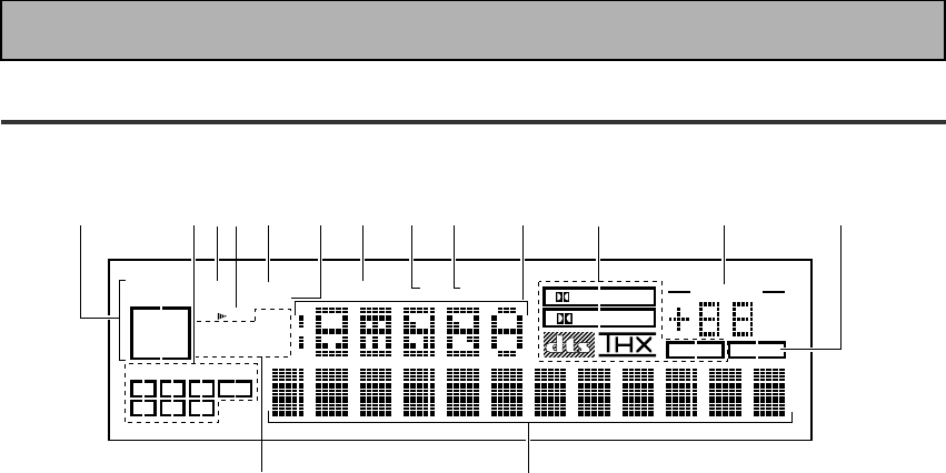
Display
All the display information is explained and/or referenced here.
4 Speaker indicators
Light to indicate the current speaker system, A
and/or B.
5 LOUDNESS indicator (See p.50)
Lights when the LOUDNESS mode is on.
6 H.P (headphones)
Lights when headphones are connected to the
PHONES jack (speakers systems A and B both
turn off automatically).
7 MIDNIGHT indicator (See p.50)
Lights when the MIDNIGHT LISTENING mode
is on.
8 DSP indicator (See p.42-46,48)
Light when a DSP or Advanced Theater modes
are selected.
9 STEREO indicator
Lights when a STEREO mode is selected.
10 Function indicator
Displays the function.
11 2/dts/MPEG mode indicators
2 DIGITAL : When the 2 /dts/MPEG mode on
the receiver is on, this indicator lights to indicate
playback of a Dolby Digital signal. However, 2
PRO LOGIC lights during 2 channel playback of
Dolby Digital.
2 PRO LOGIC : When the 2 /dts/MPEG mode
on the receiver is on, this indicator lights during 2
channel playback.
dts : Lights when DTS signals are input.
THX: Lights when the HOME THX CINEMA mode
is selected.
MPEG: Lights when MPEG signals are input.
12
MASTER VOLUME indication
Displays current volume level.
1 SIGNAL SELECT indicators
Light to indicate the input signal you selected.
ANALOG : Lights when analog signals are
assigned.
DIGITAL : Lights when digital audio signals are
selected.
AC-3 RF : Lights when AC-3 RF signals are
assigned.
AUTO : Lights when the receiver is set to select
the input signal automatically.
2
Program Format indicators
AC-3 : Lights when a source with Dolby Digital
signals is played.
DTS: Lights when a source with DTS audio signals
is played.
MPEG: Lights when a source with MPEG audio
signals is played.
For Dolby Digital or DTS sources, these
indicators change according to which channels
are active in the source. When all three LS (left
surround), S (surround) and RS (right surround)
light at the same time it means a Source with
Surround EX or DTS-ES flag is being used.
L – Left front channel.
C – Center channel.
R – Right front channel.
LS – Left surround channel.
S – Surround channel (mono).
RS – Right surround channel.
LFE – Low Frequency Effects channel.
3 Analog level indicators
OVER – When the source signal is analog, this
lights if the signal is in danger of distorting.
Press INPUT ATT on the remote control to
lower the signal level.
ATT – Lights when INPUT ATT is used to
reduce the level of the analog source signal.
DIGITAL
dB
PRO LOGIC
STEREO
DSP
MIDNIGHTLOUDNESSATTSIGNAL
SELECT OVER H.P
ANALOG
SP AB
LCRLFE
LS S RS
DIGITAL
AC-3RF
AUTO
TAPE 2
VOLUME
AC-3DTS MPEG
EON
RDS
RF ATT
MPEG
MONO STEREO
TUNED AMFM
134 56789 10 11 12 13
14
15
2
Displays & Controls

23
En
PREPARATION
Displays & Controls
13
TAPE 2 indicator
Lights when the TAPE 2 monitor is on.
14
Character display
Displays sound modes, general information.
15
Tuner indicators
MONO: Lights when the tuner is set to receive
FM broadcasts and when selected MPX mode.
STEREO: Lights when a FM stereo broadcast is
received in the auto stereo mode.
TUNED: Lights when a broadcast is received.
AM/FM: Light to indicate the current band (FM or
AM).
EON: Lights when an RDS stations transmitting
the EON data service is being received.
RF ATT: Lights when the RF attenuator is on.
RDS: Lights when RDS broadcast is being
received.
24
En
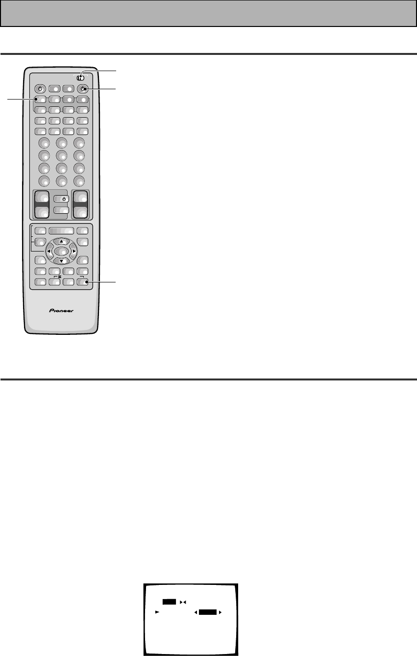
Remote Control
1 USE/SETUP slide switch
Use to put the remote into receiver SETUP, or
receiver USE mode.
2 SOURCE button
Use to turn on the power of your other
components after you have recalled or taught
the signals to this remote control.
MULTI OPERATION button
Use this button to start the MULTI OPERATION
mode. See page 78-79 for how to program and
use the MULTI OPERATION mode.
SYSTEM OFF button
This button turns off components in two ways.
First, when pressed it will turn off all PIONEER
components. Secondly, any component that
has programmed into the SYSTEM OFF
settings will also be turned off (see p.80).
For example : If you programmed power on for
your TV and VCR, pressing the SYSTEM OFF
button will turn off these components even if
they are not PIONEER products.
RECEIVER button
Press to turn power of the receiver on or to
STANDBY (off).
3 MULTI CONTROL buttons
Use these to select a source and the
corresponding remote operation mode.
For example, pressing TUNER selects the built
in tuner and sets the remote operation to the
tuner functions.
4 Component Control buttons
Use to control specific components, like a CD
player or DVD player, after you have
programmed the remote control to do these
operations (see pages 65–68) and the remote is
put in that operation mode.
5 Number buttons
These buttons can perform a variety of
different functions depending on the remote
operation mode. They are most useful for CD
and tuner operations.
6 TV CONTROL buttons
The following buttons are used to control the
TV only and can be used no matter what
function the remote control is set to.
TV button – Press to turn the power of the
TV on/off.
TV FUNC button – Press TV FUNC to select
the TV for remote control operation.
TV VOL +/- button – Use to adjust the TV
volume.
Displays & Controls
AV PRE-PROGRAMMED AND LEARNING
REMOTE CONTROL UNIT
/DTS/MPEG
S0URCE
DVD/LD TV/SAT VCR1 VCR2
CD
TV VOL
TV FUNC
MENU
ENTER
STEREO/
DIRECT
DSP
THXLIGHT
MUTE
TV
VOLUME
MD/
TAPE1 TUNER TVCONT
RECEIVER
USE SETUP
MULTI
OPERATION
CLASS MPX
DIRECT ACCESS
CHANNEL
STATION
TUNING
DISPLAY
RF ATT
TV CONTROL
FUNCTION
REMOTE SETUP
SYSTEM SETUP
INPUT
ATT
ADVANCED
MIDNIGHT
MULTI CH
INPUT
STANDARD
DIGITAL
NR
EFFECT/
CH SEL
SIGNAL
SELECT
BAND
SYSTEM
OFF
123
456
789
0
DISC
Î
¶ 873
1¡4¢
+
-
+
-
+
-
MULTI CONTROL
++
––
+
–
+10
1
2
3
4
5
76
8
9
10
25
En
PREPARATION
5(+)/∞(–)/2/3/ENTER buttons
Use to operate the on-screen menu on your TV
screen and enter commands when setting up
surround sound, speakers levels & settings,
and other set up features see p.29–41).
Specific use of these buttons is described in
conjunction with the operations they perform.
For more information see each individual
section.
DIGITAL NR button
Press to switch Digital NR on or off. (See page
49)
SIGNAL SELECT button
Press SIGNAL SELECT repeatedly to select one
of the following:
ANALOG – Analog signal.
DIGITAL – Digital signal (DVD/LD, TV/SAT, CD,
MD/TAPE 1/CD-R, VCR 1/DVR, VCR 2, LINE).
AC-3 RF – 2 RF signal (DVD/LD, TV/SAT, VCR
1, VCR 2).
AUTO – This is the default. If there are both
analog, digital, 2 RF input signals, the
receiver automatically selects the best possible
signal.
9 STEREO/DIRECT button (See p.44 & 53)
Switches the receiver into STEREO mode if it
was in a different sound mode (like ADVANCED
THEATER) or toggles between DIRECT and
STEREO mode. For more on STEREO mode
see p.53.
DIRECT playback bypasses the tone controls
and channel level for the most accurate
reproduction of a program source.
DSP button (See p.42-46, 48)
Press repeatedly to select a DSP sound mode.
/DTS/MPEG buttons (See p.42-46)
Press these buttons to put the receiver in the
selected sound mode. For more information on
the sound modes see p.85&86.
MULTI CH INPUT button
Press to switch to MULTI CH IN mode.
MIDNIGHT button (See p.50)
Switches the MIDNIGHT mode on or off.
10 LIGHT button
Press to light the remote control buttons.
7 MASTER VOLUME buttons
Use to raise or lower the volume of the
receiver.
8 INPUT ATT button (when USE mode is
selected)
Use to lower the input level of an analog signal
that is too powerful, thus causing the sound to
distort (the OVERLOAD indicator will light).
REMOTE SETUP button (when SETUP
mode is selected)
Use to customize the remote control functions
and the remote control itself. (See “Setting Up
the Remote Control to Control Other Compo-
nents“ starting on p.65, “Multi Operation“
starting on p.78)
MENU button
Use to get the various menus for your TV or
DVD.
MUTE button
Press to mute or restore the volume.
EFFECT/CH SEL,5(+)/∞(–) (when USE
mode is selected) button (see memo on
p.45)
EFFECT – Use these buttons to increase or
decrease the amount of effect applied in a DSP
or Advanced Theater mode. When the amount
of effect is increased in a DSP/Advanced
Theater mode the characteristics of that mode
become stronger and more noticeable. The
scale ranges from 10-90 with 70 as the default
setting. First turn on the DSP/Advanced
Theater you want (by pressing the DSP/
Advanced Theater button until you get the
mode) and then increase or decrease the
amount of effect.
CH SEL – You may want to adjust the channels
when listening to some sound sources. Use
this button to select the channel you want to
adjust.
SYSTEM SET UP button (when SETUP
mode is selected)
Use to set up the speaker and sound systems.
For more information see “Setting up for
Surround Sound“
starting on p.30.
FUNCTION button
Press to select a source. The button will cycle
through all the possible sources.
Displays & Controls
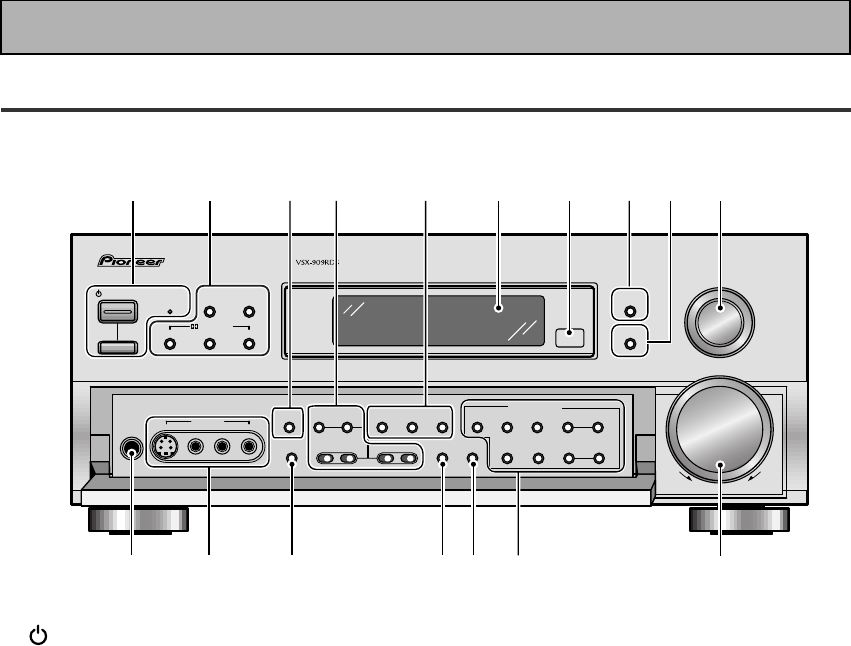
26
En
Front Panel
All the controls on the front panel are explained and/or referenced here. To open the front panel push
gently on the lower third of the panel.
1 STANDBY/ON button
Press to switch the receiver ON or into
STANDBY mode.
STANDBY indicator
Lights when the receiver is in STANDBY mode.
(Please note that this receiver consumes a
small amount of power [1.0 W] in the standby
mode.)
_ ON/ — OFF button
If the button is OFF (—), the power of the
receiver is shut off and the STANDBY/ON
button on the receiver or the remote control do
not function. Pressing the button again will
turn the receiver ON (_) and the receiver
enters the standby mode. In the standby mode,
you can turn on the receiver using the STAND-
BY/ON button on the receiver or the remote
control.
2 DSP MODE button (See p.44 & 45)
Press repeatedly to select a DSP sound mode.
(HALL 1, HALL 2, JAZZ, DANCE, THEATER 1,
or THEATER 2, 5/7 CH STEREO). Use these
modes to produce surround sound from
standard (two channel) stereo sources and
create different listening environments.
STEREO/DIRECT button (See p.44 & 53)
Switches the receiver into STEREO mode if it
was in a different sound mode (like ADVANCED
THEATER) or toggles between DIRECT and
STEREO mode. For more on STEREO mode
see p.44.
DIRECT playback bypasses the tone controls,
DIGITAL NR, LOUDNESS, MIDNIGHT and
channel level for the most accurate reproduc-
tion of a program source.
2/ DTS/ MPEG buttons (See p.42-46,
85, 86)
THX CINEMA – Cycles through the THX
CINEMA, THX SURROUND EX or THX AUTO
sound modes. If you have THX-certified
speaker setup or want to re-create a THX-style
sound environment. It is also appropriate for
Dolby Digital, Dolby Pro Logic, DTS or MPEG
sources. Those with surround back speakers
can use all three THX modes, those without
can only use the THX CINEMA mode.
ADVANCED – Use to select one of the four
Advanced Theater modes. Use to create certain
types of sound environments when listening to
Dolby Digital, Dolby Pro Logic, DTS or MPEG
sources.
STANDARD – Use for pure decoding of multi
channel sources, especially Dolby Digital, Dolby
Pro Logic, DTS or MPEG sources. Each press
toggles between STANDARD and STANDARD
7.1 mode (for use with SURROUND BACK
speakers) and STANDARD auto (the receiver
chooses the appropriate STANDARD mode).
Those with surround back speakers can use all
three STANDARD modes, those without can
only use the STANDARD mode.
STANDBY/ON
— OFF _ ON
DSP
MODE
INPUT
SELECTOR
MASTER
VOLUME
THX CINEMA ADVANCED STANDARD
STANDBY
AUDIO/VIDEO MULTI-CHANNEL RECEIVER
STEREO/
DIRECT
/DTS/MPEG
DOWN UP
PHONES
S-VIDEO VIDEO
MULTI CH
INPUT
SIGNAL
SELECT RF ATT CLASS
TUNER CONTROL
BAND TUNING
STATION
FL
DIMMER
EON
MODE
TAPE 2
MONITOR
VIDEO
SELECT
TONE
CHANNEL
SELECT LOUDNESS
DIGITAL
NR
-
+
-
+
SPEAKERS
-
TREBLE +
-
BASS +
L AUDIO R
VIDEO INPUT
CHARACTER/
SEARCH
MEMORY
12 53678109
11 12 13 14 15 16 17
4
Displays & Controls

27
En
PREPARATION
3 MULTI CH INPUT (See p.41, 52)
Use to hook up an external component that can
decode other types of signals and input them
into the VSX-909RDS/909RDS-G.
4 TONE buttons
This button has two functions. Firstly, it
switches between TONE ON and TONE
BYPASS, which bypasses the tone circuitry.
Secondly, you need to press the button before
using the CHANNEL SELECT buttons to adjust
the BASS & TREBLE (cannot be used in THX or
MULTI CH IN modes).
CHANNEL SELECT button
Switches the tone adjust controls between the
FRONT, CENTER, SURROUND and SUR-
ROUND BACK speakers. You can then use the
BASS and TREBLE controls to adjust the
sound.
BASS (–/+) buttons (See p.51)
Use to adjust low frequencies.
TREBLE (–/+) buttons (See p.51)
Use to adjust the high frequencies.
5 LOUDNESS button (See p.50)
Switches the LOUDNESS mode on or off (can
not be used in THX and MULTI CH IN.
DIGITAL NR button (See p.49)
Switches the DIGITAL NR on or off (cannot be
used in THX or MULTI CH IN mode).
SIGNAL SELECT button (See p.48)
Use to select the type of signal being input into
the receiver. Press SIGNAL SELECT repeatedly
to select one of the following:
ANALOG – To select an analog signal.
DIGITAL – To select a optical or coaxial digital
signal.
AC-3 RF – To select an 2 RF signal.
AUTO – This is the default. If there are analog,
digital and 2 RF signals input, the receiver
automatically selects the 2 RF signal. If there
are analog and digital signals input the digital
will be selected.
6 Display (See page 22)
7 Remote sensor
Point the remote control toward the remote
sensor to operate the receiver.
8 EON MODE button/indicator
Press to select the EON mode in the FM mode
(see “Setting EON” on page 64). The indicator
lights when the EON mode is selected.
9 FL DIMMER button (See p.53)
Use to adjust the brightness of the main
display.
10 INPUT SELECTOR dial
Turn to select a source component.
DVD/LD – DVD player or Laser Disc player.
TV/SAT– TV or satellite tuner.
CD – Compact Disc player.
MD/TAPE1/CD-R – Tape deck, Mini Disc
recorder or CD recorder connected to MD/
TAPE 1/CD-R inputs/outputs.
TUNER – The built-in tuner.
PHONO – Turntable.
VIDEO – Video camera (etc.) connected to the
VIDEO INPUT on the front panel.
VCR1/DVR – Video cassette recorder connect-
ed to VCR1/DVR inputs.
VCR 2 – Video cassette recorder or other
component connected to VCR 2 inputs.
11 PHONES jack
Connect headphones for private listening (no
sound will be heard through the speakers).
12 VIDEO INPUT jacks (See p.15)
S-VIDEO: Video input for connecting a video
camera (etc.), that has an S-Video out.
VIDEO / AUDIO (L/R): Video input for connect-
ing a video camera, etc. that has standard
video/audio outputs.
13
SPEAKERS (A/B) button
Use to select the speaker system. A is the
primary setting. It plays all speakers hooked up
to the A system. A & B setting only plays the
front speakers of both the A & B systems and
the subwoofer. Multi channel sources will be
down-mixed to these speakers so no sound will
be lost. B setting only plays the front speakers
connected to the B system and multi channel
sources will be down-mixed to these two
speakers. The button cycles through the
speaker systems as follows: A]B]A&B]off.
14
VIDEO SELECT button
Switches the receiver between the various
types of video input.
15 TAPE 2 MONITOR button (See p.76)
Selects the tape deck (MD recorder, etc.)
connected to the TAPE 2 MONITOR inputs/
outputs. Allows monitoring of a recording as
it's being made.
Displays & Controls

28
En
Displays & Controls
16
TUNER CONTROL buttons (See p.55-63)
CLASS button – Press repeatedly to switch
the preset station classes.
RF ATT button – Press to turn the RF attenua-
tor on when receiving strong FM signals
(nearby stations) to reduce sound distortion.
Normally, set the RF attenuator to off. This
button does not affect AM reception.
BAND button – Press to select the AM or FM
band.
TUNING –/+ button – Use to manually tune to
radio stations.
CHARACTER/ SEARCH button – Press to select
the character input mode, or initiate an RDS
PTY search (see “Memorizing a broadcast
station name” on p.59 and “Searching for a
program by program type (PTY)“ on p.63).
MEMORY button – Press to start the memori-
zation of a preset station.
STATION –/+ button – Use to choose pro-
grammed radio stations.
17
MASTER VOLUME
Adjusts the overall receiver volume.
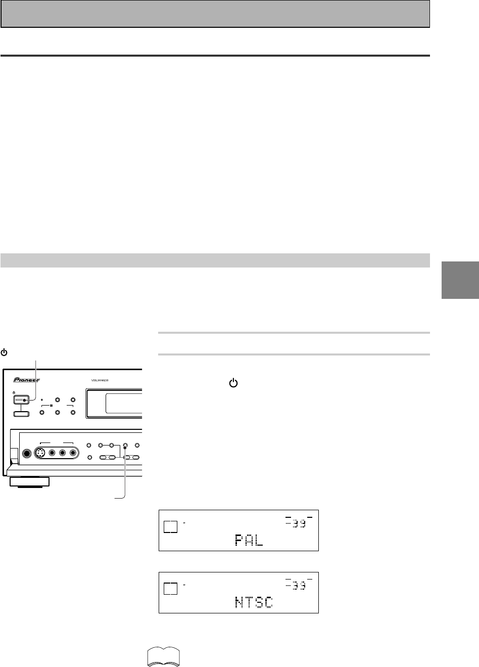
29
En
SET
UP
Switching video system between PAL and NTSC
This receiver is able to use two types of video systems for its OSD (on screen display) and you need to set the
receiver to the type of video system you have, either PAL or NTSC. If you do not match the system on the
receiver with your home system no OSD will appear on your TV. People with multi-system TVs do not need to
worry about changing the setting. If necessary, follow the instructions below to switch the type of video
system.
1 Put the receiver in the STANDBY mode.
2 While holding down the LOUDNESS button,
press the STANDBY/ON button.
The video system type will change depending on the state the
receiver was previously in. The new type, either PAL or NTSC,
will appear in the display. It will be shown for about seven
seconds and then the receiver returns to normal operating
mode.
To change the video system type again repeat steps 1 and 2.
Make sure you press the LOUDNESS button, using others
buttons may change this receiver’s settings.
dB
SIGNAL
SELECT
SP A
DIGITAL
VOLUME
When a PAL system is selected
dB
SIGNAL
SELECT
SP A
DIGITAL
VOLUME
When a NTSC system is selected
When using the PAL setting the OSD does not get displayed
in color.
On Screen Display
There are a number of possible ways to hook up the receiver to your video components, like a DVD player, and
hook up to your receiver to your TV, but some of them will not allow you to use the on-screen display of this
unit. To avoid this, you simply need to keep the following rules:
1Always use the same type of video cords to hook up your video components to the receiver as you use to
hook up the receiver to your TV. For example, if you use composite video cords to hook up your DVD player
to the receiver, use composite video cords to hook up the receiver to your TV. If you use S video cords to
hook up your DVD player and the receiver, use S video cords to hook up the receiver to your TV.
2Always make sure your TV is set to the appropriate input channel (for example, video 1). Your TV may have a
number of input channels and if you do not select the proper one, you will not be able to use this receiver’s
on-screen display, or, in fact see any picture from this receiver at all. If you are unsure how to choose an
input channel for your TV, refer to the manual which came with your TV.
You might, for example, use both composite and S video cords to hook up your video components with this
receiver and then use composite video cords to hook up this receiver to your TV. This arrangement would still
NOT let you see the on-screen displays from this receiver on your TV. The best idea is just to use one type of
video cords for all your video component and TV hook ups.
STANDBY/ON DSP
MODE
THX CINEMA ADVANCED STANDARD
STANDBY
AUDIO/VIDEO MULTI-CHANNEL RECEIVER
STEREO/
DIRECT
/DTS/MPEG
PHONES
S-VIDEO VIDEO
MULTI CH
INPUT TONE
CHANNEL
SELECT LOUDNESS
DIGITAL
NR
SPEAKERS
-
TREBLE +
-
BAS S +
L AUDIO R
VIDEO INPUT
— OFF _ ON
STANDBY/ON
LOUDNESS
memo
Initial Set Up
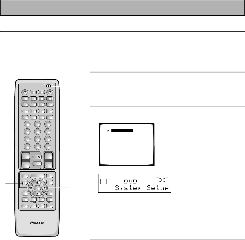
30
En
Setting Up for Surround Sound
To ensure the best possible surround sound, be sure to complete the following setup operations. You only need
to make these settings once (unless you change the placement of your current speaker system or add new
speakers, etc.).
This receiver uses on-screen displays to make setting up your home cinema system easier. Switch on the
receiver and your TV, and make sure that the receiver is selected as your TV's video input.
1 Set the slide switch to SETUP.
Also make sure your TV is on and set to the receiver.
• When you're done setting up the receiver, remember to
set the slide switch back to USE.
2 Press the SYSTEM SETUP button.
System Setup
[Digital-In Select]
[Speaker Setting]
[Channel Delay]
[Channel Level]
[Crossover Network]
[Bass Peak Level]
[D-Range Control]
[Multi Channel In]
dB
STEREO
SIGNAL
SELECT
ANALOG
SP A
AUTO
VOLUME
This display appears on the receiver.
• You can escape from this screen at any time by pressing the
SYSTEM SETUP button again. None of the settings you
made will be entered in this case.
• If you don't enter any settings the receiver will revert back to
its previous state after three minutes.
3 Press the 5 or ∞ arrow buttons to move the
hand to the mode you want. Then press the
ENTER button.
In each mode, the current settings are displayed automatically.
We suggest you adjust all these settings when you first hook
up the receiver. That gets them out of the way and you won't
need to return to this setting mode unless you change your
home set up by adding new speakers (etc.). The sound set up
modes explained here are:
Digital In Select (See p.32)
In order to use your digital components you must match the
numbered digital input settings with the numbered digital jacks
used by your digital components.
Speaker Setting (See p.33-34)
Use to specify the type and number of speakers you connect-
ed.
Initial Set Up
AV PRE-PROGRAMMED AND LEARNING
REMOTE CONTROL UNIT
1
3
2
/DTS/MPEG
S0URCE
DVD/LD TV/SAT VCR1 VCR2
CD
TV VOL
TV FUNC
MENU
ENTER
STEREO/
DIRECT
DSP
THXLIGHT
MUTE
TV
VOLUME
MD/
TAPE1 TUNER TVCONT
RECEIVER
USE SETUP
MULTI
OPERATION
CLASS MPX
DIRECT ACCESS
CHANNEL
STATION
TUNING
DISPLAY
RF ATT
TV CONTROL
FUNCTION
REMOTE SETUP
SYSTEM SETUP
INPUT
ATT
ADVANCED
MIDNIGHT
MULTI CH
INPUT
STANDARD
DIGITAL
NR
EFFECT/
CH SEL
SIGNAL
SELECT
BAND
SYSTEM
OFF
123
456
789
0
DISC
Î
¶ 873
1¡4¢
+
-
+
-
+
-
MULTI CONTROL
++
––
+
–
+10
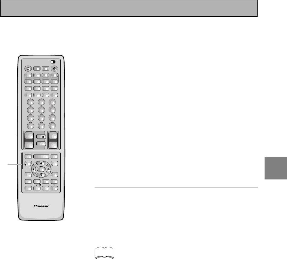
31
En
SET
UP
Channel Delay (See p.35)
Set up all your speakers for the most realistic surround sound.
Adding a slight delay to some speakers enhances sound
separation and is particularly important for achieving a surround
sound effect. You need to figure out the distance from your
listening position to your speakers to add the proper delay.
Channel Level (See p.36-37)
Use to balance the volumes of your different speakers.
Crossover Network (See p.38)
This feature lets you select which bass frequencies will be sent
to the subwoofer or front speakers.
Bass Peak Level (See p.39)
Dolby Digital, DTS and MPEG audio sources include ultra-low
bass tones. Set the bass peak level as needed to prevent the
ultra-low bass tones from distorting the sound from the
speakers.
Dynamic Range Control (See p.40)
This feature makes possible excellent surround sound effects
when listening to Dolby Digital sources at low volumes.
Multi Channel In Setting (See p.41)
This feature lets you hook up a multi channel external decoder
that may give a higher quality when decoding discs.
4 Go on to the next page to continue set up.
If you don't want to make any settings go can exit this setup.
To exit the SYSTEM SETUP MENU and on-screen display press
SYSTEM SETUP button again.
After you complete one of the SYSTEM SETUP menus
and return to the basic SYSTEM SETUP screen the
receiver automatically moves the cursor to the next
SYSTEM SETUP menu. For example, if you've complet-
ed SPEAKER SETTINGS and returned to the basic
SYSTEM SETUP screen, CHANNEL DELAY will be
selected automatically. You can notice this on your TV
screen.
memo
AV PRE-PROGRAMMED AND LEARNING
REMOTE CONTROL UNIT
4
/DTS/MPEG
S0URCE
DVD/LD TV/SAT VCR1 VCR2
CD
TV VOL
TV FUNC
MENU
ENTER
STEREO/
DIRECT
DSP
THXLIGHT
MUTE
TV
VOLUME
MD/
TAPE1 TUNER TVCONT
RECEIVER
USE SETUP
MULTI
OPERATION
CLASS MPX
DIRECT ACCESS
CHANNEL
STATION
TUNING
DISPLAY
RF ATT
TV CONTROL
FUNCTION
REMOTE SETUP
SYSTEM SETUP
INPUT
ATT
ADVANCED
MIDNIGHT
MULTI CH
INPUT
STANDARD
DIGITAL
NR
EFFECT/
CH SEL
SIGNAL
SELECT
BAND
SYSTEM
OFF
123
456
789
0
DISC
Î
¶ 873
1¡4¢
+
-
+
-
+
-
MULTI CONTROL
++
––
+
–
+10
Initial Set Up
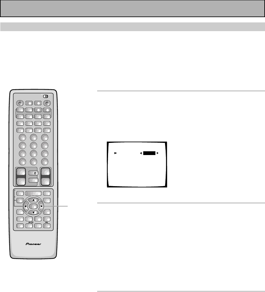
32
En
1 DIGITAL IN SELECT should be selected (if it
isn't use the 5¥∞ buttons to select it).
See “Setting Up for Surround Sound“ on page 30 if you need
more information.
Press the ENTER button.
Digital-In Select
Digital-1
Digital-2
Digital-3
Digital-4
Digital-5
AC-3 RF
[EXIT] L
[DVD/LD]
[ CD ]
[ MD ]
[TV/SAT ]
[ VCR1 ]
[DVD/LD]
2 Choose a DIGITAL IN and assign it an input
function.
Use 2 or 3 to choose the input function that matches the
component hooked up to that digital terminal.
The possible choices include: DVD/LD, TV/SAT, CD, MD/TAPE1/
CD-R, VCR 1/DVR, VCR 2. You cannot assign digital inputs to
the TUNER, VIDEO, PHONO, and TAPE 2 MONITOR functions.
If you assign a function (for example DVD/LD) that was
previously assigned to a different Digital In the second Digital In
will automatically revert to an OFF setting. This is because one
function cannot be assigned twice.
3 Select EXIT and press ENTER button to
return to the SYSTEM SETUP MENU.
If you want to change a setting before proceeding simply
use the arrow buttons to go back.
• For the Digital 1-5 setting you can choose between DVD/
LD, CD, TV/SAT, MD/TAPE 1/CD-R, VCR 1/DVR and VCR 2
functions.
• For the AC-3 RF setting you can choose between DVD/LD,
TV/SAT, VCR 1/DVR and VCR 2 functions.
Remember, if you have a DVD/LD player or LD player you
should hook it up to the analog and digital jacks in addition to
the 2 RF connection described here.
Digital-In Select
In order to be able to use your digital equipment properly you need to assign digital inputs for each of the digital
components you connected. Match the Digital 1-5 settings with the digital jacks 1-5 in accordance with what is
connected to each digital jack. Check the digital jack numbers on the back of the receiver to make certain what
component is in which jack (if necessary, see page 13 for more on digital connections). The last setting, the AC-
3 RF setting, is specifically for a DVD/LD player or LD player with an 2 RF output. If you connected one of
these components match this button to the component. If continuing from the last page go to step 1. If starting
fresh, complete steps 1-3 in “Setting Up for Surround Sound“ (p.30) first.
AV PRE-PROGRAMMED AND LEARNING
REMOTE CONTROL UNIT
1-3
/DTS/MPEG
S0URCE
DVD/LD TV/SAT VCR1 VCR2
CD
TV VOL
TV FUNC
MENU
ENTER
STEREO/
DIRECT
DSP
THXLIGHT
MUTE
TV
VOLUME
MD/
TAPE1 TUNER TVCONT
RECEIVER
USE SETUP
MULTI
OPERATION
CLASS MPX
DIRECT ACCESS
CHANNEL
STATION
TUNING
DISPLAY
RF ATT
TV CONTROL
FUNCTION
REMOTE SETUP
SYSTEM SETUP
INPUT
ATT
ADVANCED
MIDNIGHT
MULTI CH
INPUT
STANDARD
DIGITAL
NR
EFFECT/
CH SEL
SIGNAL
SELECT
BAND
SYSTEM
OFF
123
456
789
0
DISC
Î
¶ 873
1¡4¢
+
-
+
-
+
-
MULTI CONTROL
++
––
+
–
+10
Initial Set Up
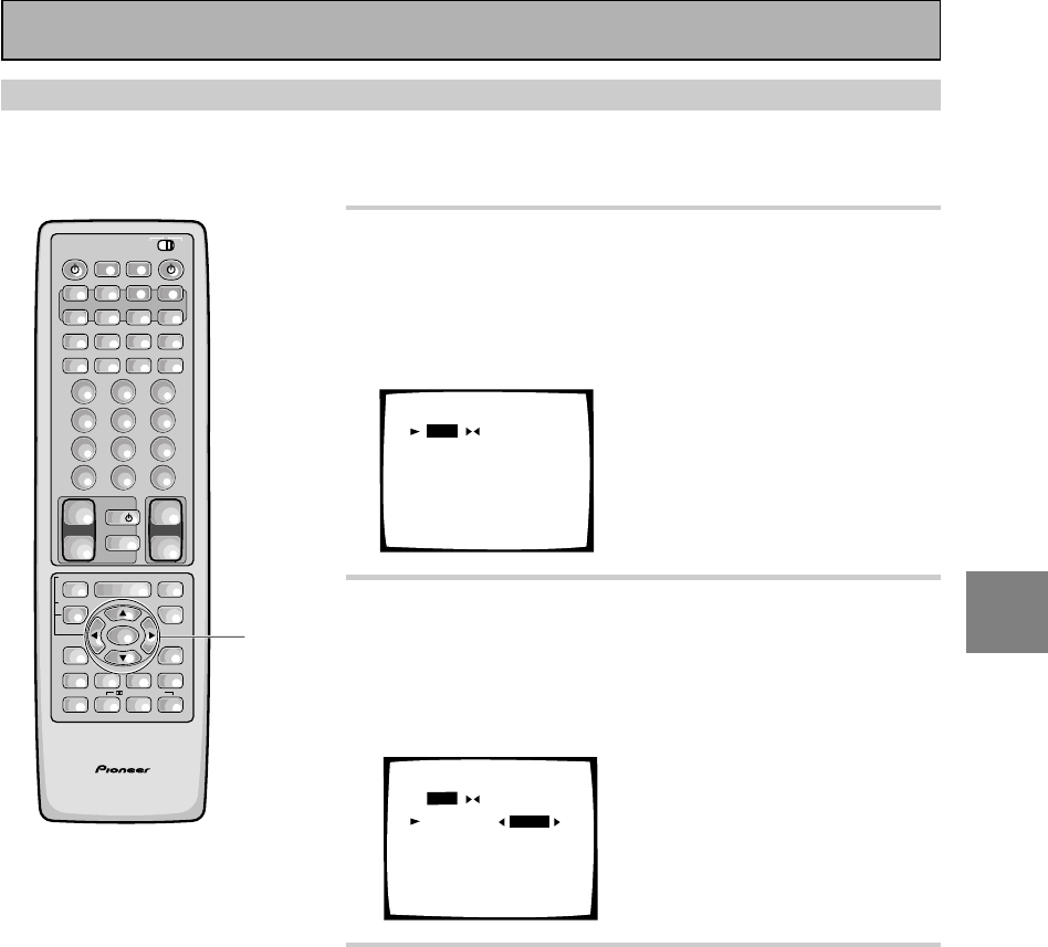
33
En
SET
UP
Speaker Setting
The following steps show you how to specify the type of speakers you connected. Use the 5¥∞ and 2¥3
buttons to make a selection from the on-screen menus, and use the ENTER button to register the information. If
continuing from the previous page go to step 1. If starting fresh, complete steps 1-3 on p.30 first.
1 Select SPEAKER SETTING (if continuing from
last set up, it will already be selected) with the
5¥∞ buttons then press the ENTER button.
See “Setting Up for Surround Sound“
on page 30 if you are
unsure how to do this.
Speaker Setting
[FREE] [THX]
[LARGE]
[LARGE]
[LARGE]
[LARGEx2]
[ YES ]
Front L
Center
Surround
SurrBack
Subwoofer
[EXIT]
2 Select a speaker setting mode with the 2¥3
buttons then press the ∞ button.
To specify each speaker individually select FREE.
If you connected a complete set of THX speakers select THX
and skip the SURROUND BACK part of step 3.
Speaker Setting
[FREE] [THX]
[LARGE]
[LARGE]
[LARGE]
[LARGEx2]
[ YES ]
Front L
Center
Surround
SurrBack
Subwoofer
[EXIT]
3 Specify the type of speakers you connected.
See the explanations below for the meaning
of each size.
1Press 2 or 3 to move the hand to LARGE (or LARGE X2), SMALL
(or SMALL X2), or NO (you can't select NO for the FRONT
speakers). For the subwoofer you can select YES, NO, or PLUS.
See below for a detailed explanation of every speaker choice.
2Press ∞.
3Repeat 1 and 2 for each speaker.
Depending on your choices the sound will be routed
differently, as explained here.
FRONT (default setting is LARGE)
• Select SMALL to send bass frequencies to the subwoofer.
• Select LARGE if your speakers will reproduce bass frequen-
cies effectively or if you did not connect a subwoofer.
(If you select SMALL for the front speakers the subwoofer will
automatically be set to YES. Also, the center, surround and
surround back speakers cannot be set to LARGE if the front
speakers are set to SMALL. In this case, all bass frequencies
are sent to the subwoofer.)
AV PRE-PROGRAMMED AND LEARNING
REMOTE CONTROL UNIT
1-3
/DTS/MPEG
S0URCE
DVD/LD TV/SAT VCR1 VCR2
CD
TV VOL
TV FUNC
MENU
ENTER
STEREO/
DIRECT
DSP
THXLIGHT
MUTE
TV
VOLUME
MD/
TAPE1 TUNER TVCONT
RECEIVER
USE SETUP
MULTI
OPERATION
CLASS MPX
DIRECT ACCESS
CHANNEL
STATION
TUNING
DISPLAY
RF ATT
TV CONTROL
FUNCTION
REMOTE SETUP
SYSTEM SETUP
INPUT
ATT
ADVANCED
MIDNIGHT
MULTI CH
INPUT
STANDARD
DIGITAL
NR
EFFECT/
CH SEL
SIGNAL
SELECT
BAND
SYSTEM
OFF
123
456
789
0
DISC
Î
¶ 873
1¡4¢
+
-
+
-
+
-
MULTI CONTROL
++
––
+
–
+10
Initial Set Up
34
En
CENTER (default setting is LARGE)
• Select LARGE if your speaker will reproduce bass frequen-
cies effectively.
• Select SMALL to send bass frequencies to the other
speakers or the subwoofer.
• If you did not connect a center speaker, select NO. In this
case, the center channel is output from the front speakers.
SURROUND (default setting is LARGE)
• Select LARGE if your speakers will reproduce bass frequen-
cies effectively.
• Select SMALL to send bass frequencies to the other
speakers or subwoofer.
• If you did not connect surround speakers select NO. In this
case, the sound of the surround channels is output from the
front and center speakers.
• If the SURROUND speakers are set to SMALL, the SUR-
ROUND BACK speakers will automatically be set to SMALL.
SUBWOOFER (default setting is YES)
• Select YES if you connected a subwoofer.
• If you did not connect a subwoofer select NO. In this case,
the bass frequencies are output from the front or surround
speakers.
• Choose the PLUS setting if you want stronger reproduction
of deep bass sounds.
• If you select PLUS the bass frequencies that would normally
come out the front and center speakers are all routed to the
subwoofer.
• If you selected SMALL for the FRONT speakers the
subwoofer will automatically be set to yes (you won’t be
able to choose no or PLUS).
SURROUND BACK (default setting is LARGE X2)
NOTE: In order to use SURROUND BACK speakers you
need to hook them up through an external amplifier (see p.
19 & 21) for more on this.
• Select the number and size of SURROUND BACK speakers
you have. You can choose one speaker, two or none.
• If the FRONT speakers or the SURROUND speakers are set
to SMALL, the SURROUND BACK speakers will automatical-
ly be set to SMALL.
• If you chose THX in step 2 then the SURROUND BACK
speakers can only be set to SMALL (or NO).
• Select LARGE if your speakers will reproduce bass frequen-
cies effectively.
• Select SMALL to send bass frequencies to the other
speakers or subwoofer.
• If you did not connect surround back speakers select NO.
4 Select EXIT with the 5¥∞ buttons and press
ENTER button to return to the SYSTEM
SETUP MENU.
Next, proceed to CHANNEL DELAY on the next page.
If you have a subwoofer and like
lots of bass, it may seem logical to
select LARGE for your FRONT
speakers and leave the subwoofer
selected. This may not, however,
yield the best bass results. Depend-
ing on the size and shape of your
room you may actually experience a
decrease in the amount of bass due
to what is called "low frequency
cancellations." If you have a sub-
woofer, listen to the bass response
with the FRONT speakers set to
LARGE and SMALL alternatively
and let your ears judge which
sounds best.
If you have a subwoofer, the safest
option is to route all the bass
sounds to it by selecting SMALL for
the FRONT speakers.
memo
AV PRE-PROGRAMMED AND LEARNING
REMOTE CONTROL UNIT
4
/DTS/MPEG
S0URCE
DVD/LD TV/SAT VCR1 VCR2
CD
TV VOL
TV FUNC
MENU
ENTER
STEREO/
DIRECT
DSP
THXLIGHT
MUTE
TV
VOLUME
MD/
TAPE1 TUNER TVCONT
RECEIVER
USE SETUP
MULTI
OPERATION
CLASS MPX
DIRECT ACCESS
CHANNEL
STATION
TUNING
DISPLAY
RF ATT
TV CONTROL
FUNCTION
REMOTE SETUP
SYSTEM SETUP
INPUT
ATT
ADVANCED
MIDNIGHT
MULTI CH
INPUT
STANDARD
DIGITAL
NR
EFFECT/
CH SEL
SIGNAL
SELECT
BAND
SYSTEM
OFF
123
456
789
0
DISC
Î
¶ 873
1¡4¢
+
-
+
-
+
-
MULTI CONTROL
++
––
+
–
+10
Initial Set Up
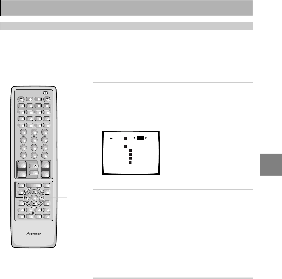
35
En
SET
UP
1 Select CHANNEL DELAY (if continuing from
last set up, it will already be selected).
See “Setting Up for Surround Sound“
on page 30 if you are
unsure how to do this.
Press the ENTER button.
Channel Delay
Front L
Center
Front
Surround
Surr Back
Surr Back
Surround
Subwoofer
[EXIT]
L
R
R
R
L
L
[2.0m]
[2.0m]
[2.0m]
[2.0m]
[2.0m]
[2.0m]
[2.0m]
[2.0m]
• The default setting is 2.0 m.
2 Use the 5¥∞ buttons to select a speaker.
Specify the distance from your listening
position to each speaker using the
commands below.
1Pres 2 or 3 to adjust the speaker distance in 10 centimeter
increments from 0.1 to 9 meters.
The default setting is 2 meter.
2Use the 5¥∞ buttons to move to the next set of speakers.
3Repeat for each speaker.
• Sound takes about 1 millisecond to travel 30 centimeter.
3 Select EXIT with the 5¥∞ buttons and press
ENTER button to return to the SYSTEM
SETUP MENU.
Next, proceed to CHANNEL LEVEL on the next page.
If you want to change a setting before proceeding simply
use the arrow buttons to go back.
Channel Delay
Adding a slight delay to some speakers is necessary to achieve a surround sound effect. You need to figure out
the distance from your listening position to your speakers to add the proper delay. The following steps show you
how to set the delay time for each channel by specifying the distances from your listening position to each
speaker. Once you specify the speaker distances, the receiver calculates the correct delay times automatically.
If continuing from Speaker Setting go to step 1. If starting fresh, complete steps 1-3 in “Setting Up for Surround
Sound“ (p.30) first.
Initial Set Up
AV PRE-PROGRAMMED AND LEARNING
REMOTE CONTROL UNIT
1-3
/DTS/MPEG
S0URCE
DVD/LD TV/SAT VCR1 VCR2
CD
TV VOL
TV FUNC
MENU
ENTER
STEREO/
DIRECT
DSP
THXLIGHT
MUTE
TV
VOLUME
MD/
TAPE1 TUNER TVCONT
RECEIVER
USE SETUP
MULTI
OPERATION
CLASS MPX
DIRECT ACCESS
CHANNEL
STATION
TUNING
DISPLAY
RF ATT
TV CONTROL
FUNCTION
REMOTE SETUP
SYSTEM SETUP
INPUT
ATT
ADVANCED
MIDNIGHT
MULTI CH
INPUT
STANDARD
DIGITAL
NR
EFFECT/
CH SEL
SIGNAL
SELECT
BAND
SYSTEM
OFF
123
456
789
0
DISC
Î
¶ 873
1¡4¢
+
-
+
-
+
-
MULTI CONTROL
++
––
+
–
+10
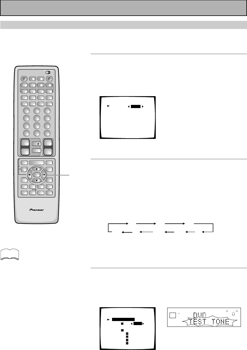
36
En
Channel Level
The following steps show you how to balance the sound output level of your speakers. Proper speaker
balance is essential for obtaining high quality surround sound. If continuing from Channel Delay go to step
1. If starting fresh, complete steps 1-3 in “Setting Up for Surround Sound“ (p.30) first.
1
Select CHANNEL LEVEL (if continuing from
CHANNEL DELAY, it will already be selected).
See “Setting Up for Surround Sound“ on page 30 if you are
unsure how to do this.
Press the ENTER button.
Channel Level
Test Tone [ AUTO ]
[Setting Start ]
[EXIT]
NOTE : Be prepared! The test tone is output at a high
volume level.
2 Select a TEST TONE mode.
1Press 2 or 3 to move the hand to AUTO or MANUAL.
2Press ∞ button to select SETTING START.
AUTO (automatic TEST TONE)
This mode switches the test tone between each speaker
automatically. Use this mode when balancing the speaker
levels by ear.
The automatic test tone is output in the following order:
MANUAL (manual TEST TONE)
This mode lets you switch the test tone between each speaker
manually. You can use this mode when you want to balance the
speaker levels by ear at a more leisurely pace.
3 After selecting SETTING START with the ∞
button press ENTER button. Test tone will
be output.
These settings will be displayed on your TV.
[ 0.0dB]
[ 0.0dB]
[ 0.0dB]
[ 0.0dB]
[ 0.0dB]
[ 0.0dB]
[ 0.0dB]
[ 0.0dB]
Channel Level
Front L
Center
Front
Surround
Surr Back
Surr Back
Surround
Subwoofer
L
RR
R
L
L
Test Tone [ AUTO ]
[Setting OK ]
It takes a moment for the machine to set itself. MASTER VOLUME
rotates to the reference position (0dB), and the test tone is output.
To exit before outputting the TEST TONE
Press the ENTER button.
To exit while outputting the TEST TONE
Press the SYSTEM SETUP button.
FL CT FR
SR
SL
SW SBL SBR
AV PRE-PROGRAMMED AND LEARNING
REMOTE CONTROL UNIT
1-3
/DTS/MPEG
S0URCE
DVD/LD TV/SAT VCR1 VCR2
CD
TV VOL
TV FUNC
MENU
ENTER
STEREO/
DIRECT
DSP
THXLIGHT
MUTE
TV
VOLUME
MD/
TAPE1 TUNER TVCONT
RECEIVER
USE SETUP
MULTI
OPERATION
CLASS MPX
DIRECT ACCESS
CHANNEL
STATION
TUNING
DISPLAY
RF ATT
TV CONTROL
FUNCTION
REMOTE SETUP
SYSTEM SETUP
INPUT
ATT
ADVANCED
MIDNIGHT
MULTI CH
INPUT
STANDARD
DIGITAL
NR
EFFECT/
CH SEL
SIGNAL
SELECT
BAND
SYSTEM
OFF
123
456
789
0
DISC
Î
¶ 873
1¡4¢
+
-
+
-
+
-
MULTI CONTROL
++
––
+
–
+10
dB
STEREO
SIGNAL
SELECT
ANALOG
SP A
AUTO
VOLUME
memo
A test tone will be output from the
SURROUND BACK speakers but your
external amplifier must be turned up
at least a little in order to hear it. Be
careful that it is not turned up too much
because the test tone volume is quite
loud.
Initial Set Up
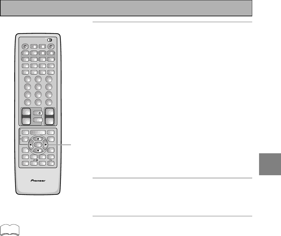
37
En
SET
UP
4 Adjust speaker levels so that you hear the
test tone at the same volume from each
speaker when seated in your main listening
position.
Note: The volume of the subwoofer tends to sound lower than
it actually is, you may need to raise its level after testing the
sound with actual soundtracks.
In AUTO mode
1Press the 2 or 3 button to adjust the level of the speaker
outputting the TEST TONE.
In MANUAL mode
1Press the 2 or 3 button to adjust the level of the first
speaker.
2Press the 5/∞ button to switch the TEST TONE to the next
speaker.
3Repeat 1 and 2 for each speaker.
If you are using a Sound Pressure Level (SPL) meter
Take the readings from your main listening position and adjust
the level of each speaker to 75 dB SPL (C-weighted/slow
mode).
5 When you have adjusted each speaker level,
press ENTER button to return to the
previous screen.
The MASTER VOLUME will return to its original position.
6 Select EXIT with the 5/∞ buttons and press
ENTER button to return to the SYSTEM
SETUP MENU.
Next, proceed to CROSSOVER NETWORK on the next page.
If you want to change a setting before proceeding simply
use the arrow buttons to go back.
memo
AV PRE-PROGRAMMED AND LEARNING
REMOTE CONTROL UNIT
4-6
/DTS/MPEG
S0URCE
DVD/LD TV/SAT VCR1 VCR2
CD
TV VOL
TV FUNC
MENU
ENTER
STEREO/
DIRECT
DSP
THXLIGHT
MUTE
TV
VOLUME
MD/
TAPE1 TUNER TVCONT
RECEIVER
USE SETUP
MULTI
OPERATION
CLASS MPX
DIRECT ACCESS
CHANNEL
STATION
TUNING
DISPLAY
RF ATT
TV CONTROL
FUNCTION
REMOTE SETUP
SYSTEM SETUP
INPUT
ATT
ADVANCED
MIDNIGHT
MULTI CH
INPUT
STANDARD
DIGITAL
NR
EFFECT/
CH SEL
SIGNAL
SELECT
BAND
SYSTEM
OFF
123
456
789
0
DISC
Î
¶ 873
1¡4¢
+
-
+
-
+
-
MULTI CONTROL
++
––
+
–
+10
Initial Set Up
Note that it is also possible to set
channel levels temporarily. Then
follow the same procedure as
explained on this page. This function
is designed to be used when you
want to change the levels temporari-
ly to raise the level of one channel.
Using this method you can set
speaker levels in different modes,
such as, STEREO, and each DSP
mode, independently. You should
return the settings to their original
state when done. Doing the set up
procedures on this page will erase
any temporary/independent level
settings that have been made.
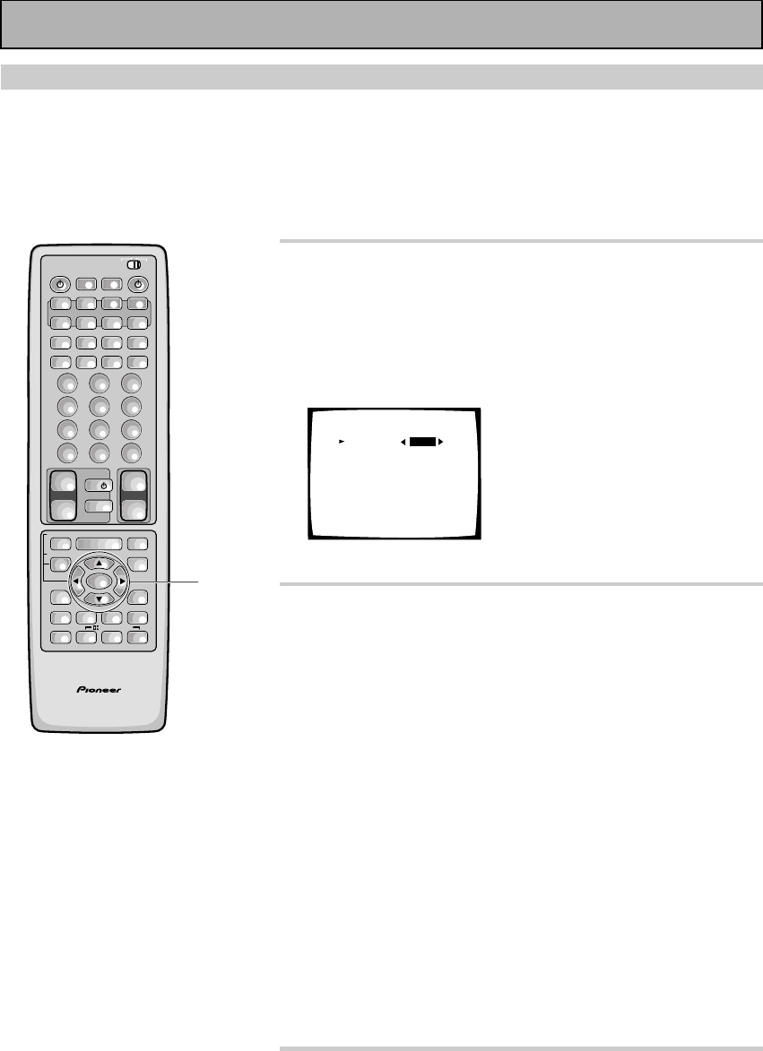
38
En
Crossover Network
The following steps show you how to adjust the crossover network. The crossover network is the frequency at
which the system divides the signal and sends the different parts to different speakers. Speaking precisely, this
setting sets the cutoff point for the bass frequencies rerouted from your SMALL speakers to your subwoofer or
speaker set to LARGE.
If continuing from Channel Level go to step 1. If starting fresh, complete steps 1-3 in “Setting Up for Surround
Sound“ (p.30) first.
1 Select CROSSOVER NETWORK (if
continuing from CHANNEL LEVEL, it will
already be selected).
See "Setting Up for Surround Sound" on page 30 if you are
unsure how to do this.
Press the ENTER button.
Crossover Network
Frequency [ 80Hz]
(THX Speaker = 80Hz)
[EXIT]
• The default setting is 80 Hz.
2 Specify the crossover frequency for your
small speakers.
Setting speakers to SMALL in “SPEAKER SETTING“ sends the
respective channel's bass frequencies to the subwoofer (or
LARGE speakers). The present function lets you determine
which frequencies will be sent to the subwoofer or LARGE
speakers.
1Use the 2 or 3 button to select 80 Hz, 100 Hz, or 150 Hz.
2Press the ∞ button.
80Hz
Sends bass frequencies below 80 Hz to the subwoofer (or
LARGE speakers).
100 Hz
Sends bass frequencies below 100 Hz to the subwoofer (or
LARGE speakers).
150 Hz
Sends bass frequencies below 150 Hz to the subwoofer (or
LARGE speakers).
Experiment with the different settings to see which sounds
best to you.
3 Select EXIT to return to the SYSTEM SETUP
MENU.
Next, proceed to BASS PEAK LEVEL on the next page.
If you want to change a setting before proceeding select a
new crossover frequency.
AV PRE-PROGRAMMED AND LEARNING
REMOTE CONTROL UNIT
1-3
/DTS/MPEG
S0URCE
DVD/LD TV/SAT VCR1 VCR2
CD
TV VOL
TV FUNC
MENU
ENTER
STEREO/
DIRECT
DSP
THXLIGHT
MUTE
TV
VOLUME
MD/
TAPE1 TUNER TVCONT
RECEIVER
USE SETUP
MULTI
OPERATION
CLASS MPX
DIRECT ACCESS
CHANNEL
STATION
TUNING
DISPLAY
RF ATT
TV CONTROL
FUNCTION
REMOTE SETUP
SYSTEM SETUP
INPUT
ATT
ADVANCED
MIDNIGHT
MULTI CH
INPUT
STANDARD
DIGITAL
NR
EFFECT/
CH SEL
SIGNAL
SELECT
BAND
SYSTEM
OFF
123
456
789
0
DISC
Î
¶ 873
1¡4¢
+
-
+
-
+
-
MULTI CONTROL
++
––
+
–
+10
Initial Set Up
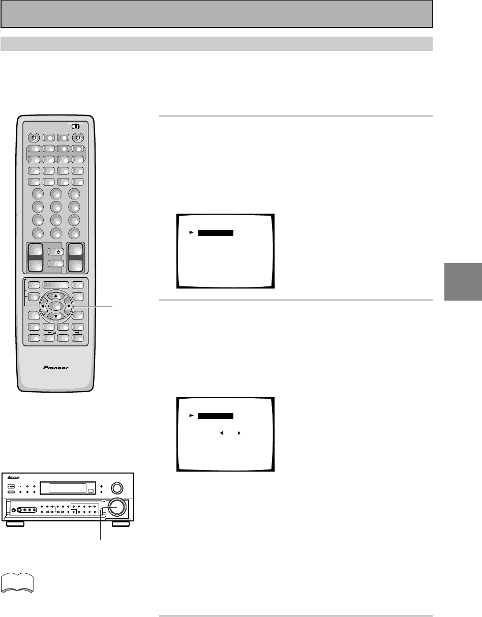
39
En
SET
UP
1 Select BASS PEAK LEVEL (if continuing
from CROSSOVER NETWORK it will already
be selected).
See “Setting Up for Surround Sound“
on page 30 if you are
unsure how to do this.
Press the ENTER button.
Bass Peak Level Manager
[Setting Start ]
[Setting Cancel]
[EXIT]
2 Output the test tone for the LFE channel
and specify the peak level.
1If your subwoofer has a volume control, set it to the middle
position before proceeding.
2Select SETTING START.
3Press the ENTER button.
Bass Peak Manager
[– 50]
[Setting OK ]
Bass Peak Level
[EXIT]
MASTER VOLUME rotates to MIN (---dB). Then the test tone
is output to the subwoofer or front or surround speakers.
4Use the 2 or 3 button arrows to gradually increase the level
of the LFE channel until the test tone begins to distort. Then
go back and leave the level setting at a point just before
that. Press the ENTER button and the receiver will remem-
ber this bass output level.
To exit before outputting the TEST TONE select EXIT and press
the ENTER button.
To exit while outputting the TEST TONE press the ENTER
button.
3 Select EXIT and press the ENTER button to
return to the SYSTEM SETUP MENU.
This completes the speaker setup.
Bass Peak Level
The LFE (Low Frequency Effect) channel in Dolby Digital, DTS or MPEG program sources can produce heavy
ultra-low bass tones that may exceed the capabilities of your speaker system. The following steps show you
how to set a maximum output level for the LFE channel. If continuing from Crossover Network go to step 1. If
starting fresh, complete steps 1-3 in “Setting Up for Surround Sound“ (p.30) first.
If you select SETTING CANCEL
no settings are input to the
receiver but the screen remains
on the TV. To escape the screen
you must select EXIT and press
the ENTER button.
memo
AV PRE-PROGRAMMED AND LEARNING
REMOTE CONTROL UNIT
1-3
/DTS/MPEG
S0URCE
DVD/LD TV/SAT VCR1 VCR2
CD
TV VOL
TV FUNC
MENU
ENTER
STEREO/
DIRECT
DSP
THXLIGHT
MUTE
TV
VOLUME
MD/
TAPE1 TUNER TVCONT
RECEIVER
USE SETUP
MULTI
OPERATION
CLASS MPX
DIRECT ACCESS
CHANNEL
STATION
TUNING
DISPLAY
RF ATT
TV CONTROL
FUNCTION
REMOTE SETUP
SYSTEM SETUP
INPUT
ATT
ADVANCED
MIDNIGHT
MULTI CH
INPUT
STANDARD
DIGITAL
NR
EFFECT/
CH SEL
SIGNAL
SELECT
BAND
SYSTEM
OFF
123
456
789
0
DISC
Î
¶ 873
1¡4¢
+
-
+
-
+
-
MULTI CONTROL
++
––
+
–
+10
MASTER VOLUME
Initial Set Up
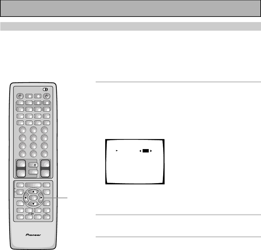
40
En
1 Select DYNAMIC RANGE CONTROL (if
continuing from BASS PEAK LEVEL, it will
already be selected).
See “Setting Up for Surround Sound“ on page 30 if you are
unsure how to do this.
Press the ENTER button.
Dynamic Range Control
Select Mode [OFF]
(For Dolby Digital)
[EXIT]
• The default setting is OFF.
• If listening at loud volumes we recommend turning the
Dynamic Range Control OFF.
2 Use the 2 or 3 arrows to choose OFF, MID
or MAX.
3 Select EXIT and press ENTER button to
return to the SYSTEM SETUP MENU.
If you want to change a setting before proceeding Choose a
new DYNAMIC RANGE CONTROL setting.
You may need to experiment with different Dolby Digital
sources before you can use the DYNAMIC RANGE CONTROL
setting to suit your low volume listening needs.
Dynamic Range Control
This feature makes it possible to enjoy full surround sound effects on Dolby Digital sources even at low
volumes. It does this by compressing the dynamic range. Dynamic range is the difference between the loudest
and the softest sounds in any given signal. Compressing the range plays sounds so the quieter ones are audible
and the louder ones don’t get distorted or become overpowering. This feature only applies to Dolby Digital
sources but the MIDNIGHT LISTENING mode accomplishes the same end for a variety of sources (see page
50). If continuing from Bass Peak Level go to step 1. If starting fresh, complete steps 1-3 in “Setting Up for
Surround Sound“ (p.30) first.
AV PRE-PROGRAMMED AND LEARNING
REMOTE CONTROL UNIT
1-3
/DTS/MPEG
S0URCE
DVD/LD TV/SAT VCR1 VCR2
CD
TV VOL
TV FUNC
MENU
ENTER
STEREO/
DIRECT
DSP
THXLIGHT
MUTE
TV
VOLUME
MD/
TAPE1 TUNER TVCONT
RECEIVER
USE SETUP
MULTI
OPERATION
CLASS MPX
DIRECT ACCESS
CHANNEL
STATION
TUNING
DISPLAY
RF ATT
TV CONTROL
FUNCTION
REMOTE SETUP
SYSTEM SETUP
INPUT
ATT
ADVANCED
MIDNIGHT
MULTI CH
INPUT
STANDARD
DIGITAL
NR
EFFECT/
CH SEL
SIGNAL
SELECT
BAND
SYSTEM
OFF
123
456
789
0
DISC
Î
¶ 873
1¡4¢
+
-
+
-
+
-
MULTI CONTROL
++
––
+
–
+10
Initial Set Up
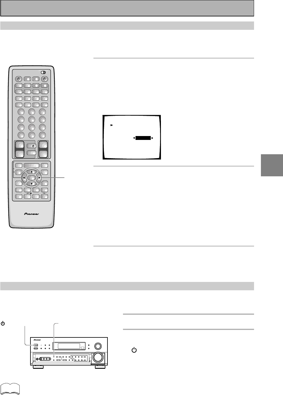
41
En
SET
UP
Multi Channel In Setting
If you have a Multi Channel external decoder you can choose whether to have the sound level set to BYPASS, in
which case only the main volume can be controlled, or to ADJUST, which means the levels can be reduced in
volume. If continuing from Dynamic Range Control go to step 1. If starting fresh, complete steps 1-3 in “Setting
Up for Surround Sound“ (p.30) first.
1 Use the 5¥∞ buttons to select MULTI
CHANNEL IN.
See “Setting Up for Surround Sound“ on page 30 if you need
more information.
Press the ENTER button.
This information will be displayed on your TV.
Multi channel in
Select mode
[Channel Level]
[EXIT]
[BYPASS]
2 Use the 2¥3 buttons to select the setting
you want, BYPASS or ADJUST.
ADJUST: Use the ADJUST setting when you want to be able
to control each channel level individually.
BYPASS:
This setting is good for getting the cleanest possible
signal. In this setting you won’t be able to change each channel
individually.
We recommend using BYPASS and the default setting is
BYPASS.
3 Use the 5¥∞ buttons to select EXIT.
Press the ENTER button.
You wil return to the SYTEM SETUP mode.
Multi Channel In Setting Using the Main Unit
You can also use the main unit to change the sound level of the MULTI CH IN. Folow the step below.
1 Put receiver in the STANDBY mode.
2 While holding down the MULTI CH
INPUT button press the
STANDBY/ON button.
The setting will change depending on what state
the receiver was previously in. For a few seconds
the display will show you which MULTI CH setting
you are now in.
MULTI CH INPUT
STANDBY/ON
AV PRE-PROGRAMMED AND LEARNING
REMOTE CONTROL UNIT
1-3
/DTS/MPEG
S0URCE
DVD/LD TV/SAT VCR1 VCR2
CD
TV VOL
TV FUNC
MENU
ENTER
STEREO/
DIRECT
DSP
THXLIGHT
MUTE
TV
VOLUME
MD/
TAPE1 TUNER TVCONT
RECEIVER
USE SETUP
MULTI
OPERATION
CLASS MPX
DIRECT ACCESS
CHANNEL
STATION
TUNING
DISPLAY
RF ATT
TV CONTROL
FUNCTION
REMOTE SETUP
SYSTEM SETUP
INPUT
ATT
ADVANCED
MIDNIGHT
MULTI CH
INPUT
STANDARD
DIGITAL
NR
EFFECT/
CH SEL
SIGNAL
SELECT
BAND
SYSTEM
OFF
123
456
789
0
DISC
Î
¶ 873
1¡4¢
+
-
+
-
+
-
MULTI CONTROL
++
––
+
–
+10
Initial Set Up
memo The default setting is BYPASS.

42
En
Sound Modes
The five sound modes on the receiver are explained here. These can be turned on from the front panel or from
the remote control.
There are three cinema modes: STANDARD, HOME THX CINEMA, and ADVANCED THEATER. These are
designed to be used with multi channel surround sound audio/visual sources (like DVDs and LDs). Intrinsic to
home theater, these modes can deliver realistic and powerful surround sound that recreates the movie theater
experience. You may need to experiment with them to see which settings suit your home system and personal
tastes.
The DSP and STEREO modes are designed to be used with music sources but some DSP modes are also suited
for film soundtracks. Again, try different settings with various soundtracks to see which you like.
You must choose one of the three cinema modes or the DSP mode in order to get surround sound. In STEREO
mode only the front two speakers, and sometimes the subwoofer (if you have one), are used.
STANDARD mode
This mode is for pure decoding of Dolby Digital, Dolby Pro Logic, DTS or MPEG sources. No special effects are
added. It is good for enjoying regular movies/videos that have been recorded in Dolby Digital, Dolby Pro Logic,
DTS or MPEG. STANDARD 7.1 is also the basic mode for enjoying sources with SURROUND BACK channels.
For more detailed information see p.85-86.You will only be able to access the second two modes if you have
hooked up SURROUND BACK speaker(s). For more detailed information see p.19, 33-34. The display will show
you what kind of source (Dolby Digital, DTS, etc.) is being played.
STANDARD
Use this mode with sources that do not have SURROUND BACK channels. If you don't have SURROUND
BACK speaker(s) switched on (see p.33-34) this is the only STANDARD mode you will be able to select on
the receiver.
STANDARD 7.1
This mode is best for sources with SURROUND BACK channels. You will only be able to access this mode
if you have set the SURROUND BACK speakers in the SPEAKER SETUP procedure (see p.33-34). Also, this
mode will play 5.1 channels sources and other sources through all the speakers you have hooked up,
routing some of the sound into your SURROUND BACK channel or channels. STANDARD 7.1 will appear in
the display even if you only have one SURROUND BACK speaker hooked up. The display will change
according to the source played.
STANDARD AUTO
In this mode the receiver will automatically select the appropriate STANDARD mode and use it to play the
soundtrack. You will only be able to access this mode if you have set the SURROUND BACK speaker(s) in
the SPEAKER SETUP procedure (see p.33-34). If the source has a Surround EX marker then the receiver
will automatically go into STANDARD 7.1 mode. This mode is best if you are unsure which of the above
STANDARD modes to use. The display will change according to the source played.
Basic Playback

OPERATION
43
En
memo
Basic Playback
HOME THX CINEMA mode
THX is a set of technical standards created by Lucasfilm, Ltd. These standards were designed to emulate a film
sound stage and thus reproduce, with the greatest possible accuracy, the soundtrack intended by the
filmmakers. To get THX sound use one the three modes explained below. You will only be able to access the
second two modes if you have hooked up SURROUND BACK speakers. For more detailed information see p.19,
33-34. The display will show you what kind of source (Dolby Digital, DTS, etc.) is being played.
THX CINEMA
Use this mode to get THX sound with sources that do not have SURROUND BACK channels. If you don't
have SURROUND BACK speaker(s) switched on (see p.33-34) this is the only THX mode you will be able to
select on the receiver.
THX SURROUND EX
This mode is specifically for using your SURROUND BACK channels with either SURROUND EX or 5.1
channel sources. You will only be able to access this mode if you have set the SURROUND BACK speakers
in the SPEAKER SETTING procedure (see p.33-34). If the source you are using is a 5.1 source then this
mode will route some of the sound to the SURROUND BACK channel(s). If the source does not have a
SURROUND EX marker or is not a 5.1 source then the display will automatically change to THX CINEMA.
THX AUTO
In this mode the receiver will automatically select the appropriate THX mode and use it to play the
soundtrack. You will only be able to access this mode if you have set the SURROUND BACK speaker(s) in
the SPEAKER SETUP procedure (see p.33-34). If the source has a Surround EX marker then the receiver
will automatically go into THX SURROUND EX mode. This mode is best if you are unsure which of the
above THX modes to use.
ADVANCED THEATER modes
The Advanced Theater mode is a newly designed system for enhancing movie soundtracks and other audio-
visual sources. It incorporates the use of DTS as well as Dolby Digital into its sound processing. These
functions switch on automatically when the source you are playing is encoded with DTS,Dolby Digital or MPEG.
There are four Advanced Theater settings that use DSP (Digital Signal Processing) to create different types of
sound environments. If you have SURROUND BACK speakers or (even just one) speaker switched on (see p.33-
34) then 7.1 will appear after the name of all of these modes in the display on the receiver. The display will show
you what kind of source (Dolby Digital, DTS, etc.) is being played.
MUSICAL
This mode is primarily for music and adds a spacious feeling to the sound. A long delay time of reflected
sounds, provides resonant tones which emulate a concert hall.
DRAMA
This mode is designed for movies with a lot of dialog. The elements of dialog are enhanced, making the
characters seem more real. The mode also compresses the dynamic range somewhat so loud sounds do
not overpower softer ones (compare this with the MIDNIGHT LISTENING mode explained on p.50).
ACTION
This mode is designed for action movies, which generally use lots of sound effects. The mode enriches the
sound to make it more realistic and extends the parameters to pick up high and low sound effects.
5/7-D THEATER
This mode is especially designed to give sound depth to stereo sources. The overall effect builds a
dynamic and broad sound space, allowing two-channel (stereo) signals to faithfully imitate a five speaker
sound. The mode should be used in conjunction with Dolby Pro Logic for sources bearing the
DOLBY SURROUND
mark.
When a Dolby Digital soundtrack is played back the Dialog Normalization function of the receiver acti-
vates automatically. Dialog Normalization is a Dolby Digital function that establishes the average dialog
level for the program source being played. If the receiver's level does not match the average dialog level,
first you see "DIAL NORM" flash in the receiver's display and next "OFFSET +4 dB" (as an example) will
appear. In this example, the number +4 dB is the difference between the receiver's gain structure and
the Dolby Digital average dialog level. To match the average dialog level, subtract or add the OFFSET
level. For example, if the OFFSET level is +4 dB, the amplifier's output is 4 dB over the average recorded
level.
44
En
DSP modes
The DSP (Digital Signal Processing) modes allow you to transform your living room into a variety of different
sonic environments when playing either two-channel or multi-channel sources. If you have SURROUND BACK
speaker(s) switched on (see p.33-34) then 7.1 will appear after the name of all of these modes in the display on
the receiver.
HALL 1
Simulates the acoustic effects of a large concert hall. Suitable for classical music. A long delay time of
reflected sounds, coupled with reverb effects, let the listener enjoy the dynamic and rich sounds
characteristic of concert halls and powerful orchestral performances.
HALL 2
Simulates the acoustic environment of a very resonant concert hall. Rich reverberation and a full sound
create the impression of a lively performance space.
JAZZ
Simulates the acoustic effects of a jazz club. Reflected sound is virtually below 100 msec so that the
listener can enjoy a live band effect.
DANCE
Simulates the acoustic effects of a dance club. Features a strong bass sound.
Reflected sound delay time is virtually below 50 msec, for the listener to enjoy the visceral power of dance
music.
THEATER 1
Reproduces theater sound field effects without losing the localization of each channel. Theater effects can
be enjoyed without losing Dolby Digital/ Pro Logic effects when used in combination those formats (with
movies bearing the
DOLBY SURROUND
trademark).
THEATER 2
Simulates the acoustic environment of a theater while maintaining proper localization of each channel.
5/7CH STEREO
Simulates the acoustic environment of a regular stereo while using all the speakers in the system to induce
a rich, all-around sound. If you have SURROUND BACK speaker(s) switched on (see p.33-34) then the name
of this mode will be 7CH SETREO in the display on the receiver. If the SURROUND BACK speakers are
switched off, then the mode will appear as 5CH STEREO.
STEREO mode
Use the STEREO mode to enjoy standard (two-channel) stereo sound from the front left and right speakers.
This mode is most like the sound reproduction you would get from a regular stereo receiver or amplifier that is
not equipped to handled A/V formats as this one is. You might want to use this mode for listening to regular
music sources (like CDs) but remember, you will only get sound from your front two speakers (and possibly
subwoofer).
Basic Playback
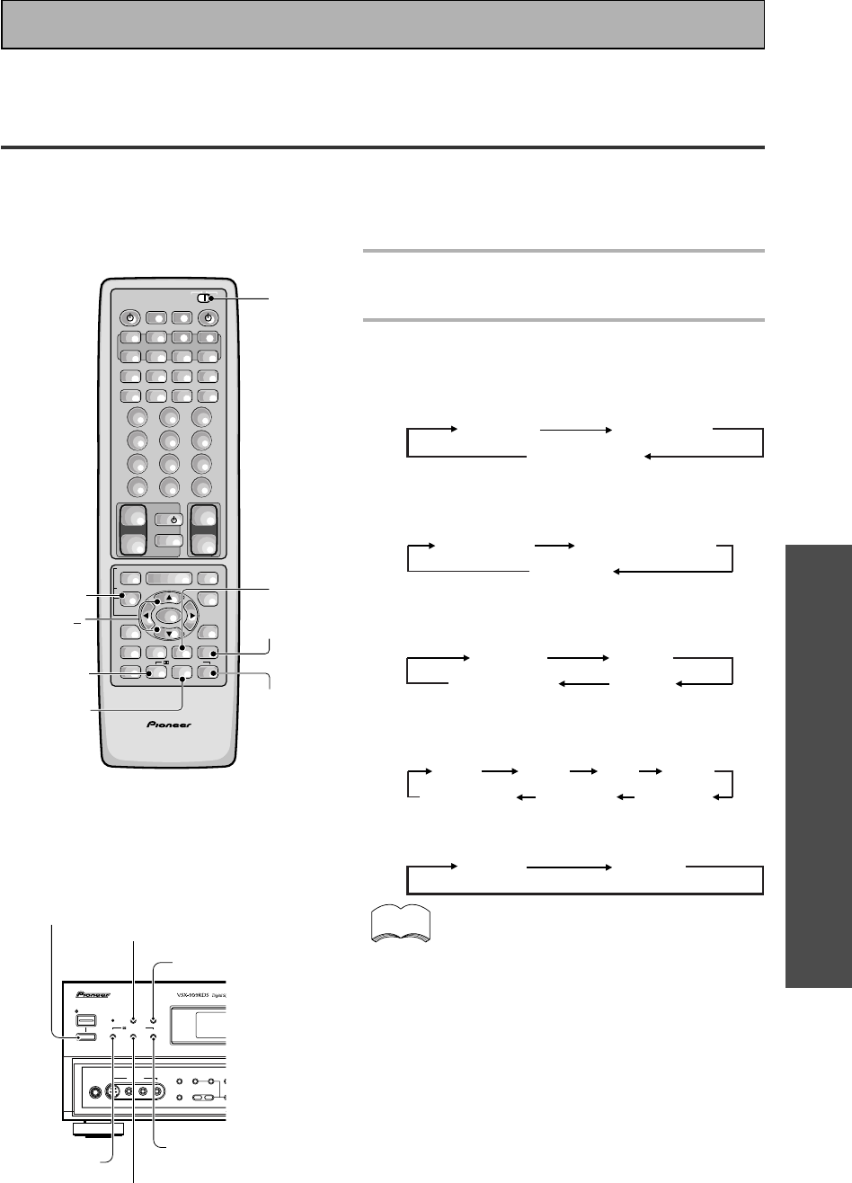
OPERATION
45
En
Selecting a Sound Mode
To ensure the best possible surround sound, be sure to complete the set up procedures described in “Setting
Up for Surround Sound” (starting on page 30) before using the sound modes. This is particularly important when
using the 2 (Dolby) Digital/MPEG or DTS sources. When using the sound modes, using SPEAKERS A will give
the best results. If you use SPEAKERS B the sound will be down mixed to the two front B speakers and the
surround sound effect will be lost.
AV PRE-PROGRAMMED AND LEARNING
REMOTE CONTROL UNIT
/DTS/MPEG
S0URCE
DVD/LD TV/SAT VCR1 VCR2
CD
TV VOL
TV FUNC
MENU
ENTER
STEREO/
DIRECT
DSP
THXLIGHT
MUTE
TV
VOLUME
MD/
TAPE1 TUNER TVCONT
RECEIVER
USE SETUP
MULTI
OPERATION
CLASS MPX
DIRECT ACCESS
CHANNEL
STATION
TUNING
DISPLAY
RF ATT
TV CONTROL
FUNCTION
REMOTE SETUP
SYSTEM SETUP
INPUT
ATT
ADVANCED
MIDNIGHT
MULTI CH
INPUT
STANDARD
DIGITAL
NR
EFFECT/
CH SEL
SIGNAL
SELECT
BAND
SYSTEM
OFF
123
456
789
0
DISC
Î
¶ 873
1¡4¢
+
-
+
-
+
-
MULTI CONTROL
++
––
+
–
+10
STEREO
STANDARD
ADVANCED
THX
DSP
1
EFFECT/
CH SEL
+/
STANDBY/ON
—OFF _ON
DSP
MODE
STANDBY
AUDIO/VIDEO MULTI-CHANNEL RECEIVER
STEREO/
DIRECT
PHONES
S-VIDEO
5-CHANNEL EQUAL POWER OUTPUT
VIDEO
MULTI CH
INPUT
CHANNEL
SELECTTONE
SPEAKERS
–
–
BASS +
L AUDIO R
VIDEO INPUT
THX CINEMA ADVANCED STANDARD
/DTS/MPEG
DSP MODE
_ON/—OFF button
STEREO/
DIRECT
STANDARD
THX CINEMA
ADVANCED
Basic Playback
1 Put the remote control slide switch
in USE.
2 Select the sound mode.
• For STANDARD \ Press STANDARD
Each press changes the STANDARD mode as
follows:
STANDARD STANDARD 7.1
STANDARD auto
• For HOME THX CINEMA \ Press THX(THX
CINEMA)
Each press changes the THX mode as follows:
THX CINEMA THX SURROUND EX
THX AUTO
• For ADVANCED THEATER \ Press ADVANCED
Each press changes the ADVANCED THEATER
mode as follows:
MUSICAL DRAMA
ACTION5/7-D THEATER
• For DSP modes \ Press DSP(DSP MODE)
repeatedly
Each press changes the DSP mode as follows:
HALL 1 HALL 2 JAZZ
5/7CH STEREO THEATER 2 THEATER 1
DANCE
• For STEREO \Press STEREO/DIRECT
Each press changes the STEREO mode as follows:
STEREO DIRECT
• If you have SURROUND BACK speakers switched
on (see p.33-34) then 7-D THEATER and 7CH
STEREO will appear as such in the display on the
receiver. If these speakers are not switched on the
above two modes will appear as 5-D THEATER and
5CH STEREO.
• The effects of ADVANCED THEATER mode can be
adjusted in the range of 10 to 90 by pressing
EFFECT +/– (The default setting is 70). Also, the
effect level can be set in each ADVANCED THE-
ATER mode by pressing the EFFECT(+/–) button.
• The amount of effect of each DSP mode can be
adjusted in the range of 10 to 90 (the default
setting value is 70) by pressing EFFECT +/–.
• 5/7CH STEREO modes cannot be changed.
memo
Before operating the receiver, be sure to press the _ ON/ — OFF button on the front panel to turn the
power ON (_).
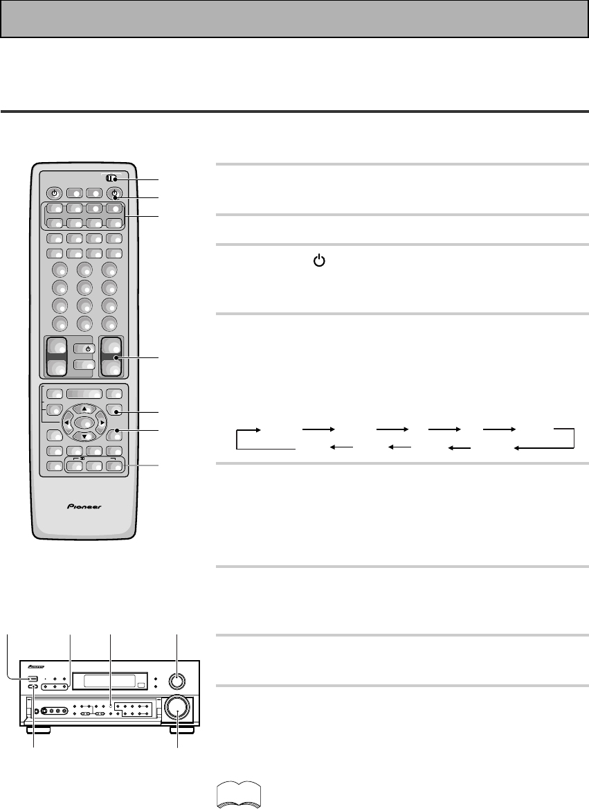
46
En
1 Turn on the power of the playback
component.
2 Put the remote control slide switch in USE.
3 Press the RECEIVER button to turn on the
receiver.
Be sure that the standby indicator turns off on the front panel.
4 Press the MULTI CONTROL buttons or the
FUNCTION button to select the source you
want to playback.
The FUNCTION button cycles through the sources in the
following order:
TUNER
MD
VCR 2 VCR 1
TV/SAT
DVD/LD
VIDEO
CD
PHONO
5 Choose a sound mode by pressing THX,
ADVANCED or STANDARD.
The default setting is STEREO.
(For more see “Sound Modes” and ”Selecting a Sound Mode”
on pages 42-45.)
6 Press the SIGNAL SELECT button to select
the input signal. Set to AUTO.
(See “Switching Analog and Digital Signal Input” on page 48.)
7 Start playback of the component you
selected in step 1.
8 Adjust the volume by using the volume
buttons on the remote control or the
MASTER VOLUME on the front panel.
• We recommend using different modes for different types of
DTS material. For watching movies, the STANDARD, THX or
ADVANCED THEATER setting should provide the best results.
For listening to music, the STANDARD, DIRECT, STEREO, or
DSP modes should serve the listener best.
• Make sure you connect your DVD/LD or LD players using the
2 RF jack. If your player has an 2 RF output this will ensure
you can use all LDs. Refer to p.14.
memo
Basic Playback
Playing Sources with Dolby Digital
, DTS or MPEG
The following instructions show you how to play Dolby Digital,DTS or MPEG sound sources with the VSX-
909RDS/909RDS-G.
AV PRE-PROGRAMMED AND LEARNING
REMOTE CONTROL UNIT
2
3
4
6
5
4
8
/DTS/MPEG
S0URCE
DVD/LD TV/SAT VCR1 VCR2
CD
TV VOL
TV FUNC
MENU
ENTER
STEREO/
DIRECT
DSP
THXLIGHT
MUTE
TV
VOLUME
MD/
TAPE1 TUNER TVCONT
RECEIVER
USE SETUP
MULTI
OPERATION
CLASS MPX
DIRECT ACCESS
CHANNEL
STATION
TUNING
DISPLAY
RF ATT
TV CONTROL
FUNCTION
REMOTE SETUP
SYSTEM SETUP
INPUT
ATT
ADVANCED
MIDNIGHT
MULTI CH
INPUT
STANDARD
DIGITAL
NR
EFFECT/
CH SEL
SIGNAL
SELECT
BAND
SYSTEM
OFF
123
456
789
0
DISC
Î
¶ 873
1¡4¢
+
-
+
-
+
-
MULTI CONTROL
++
––
+
–
+10
34
56
8
_ON/—OFF
button
Before operating the receiver, be sure to press the _ ON/ — OFF button on the front panel to turn the
power ON (_).
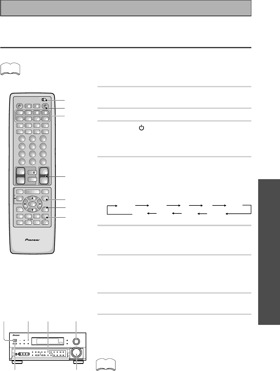
OPERATION
47
En
Basic Playback
Playing Stereo Sources
The following instructions show you how to use the receiver for stereo audio or audio-visual.
If the TAPE 2 indicator is visible in the display, it means the TAPE 2 MONITOR is on. Press TAPE 2
MONITOR on the front panel to turn it off unless you want to listen to TAPE 2.
1 Turn on the power of the playback
component.
2 Put the remote control slide switch in USE.
3 Press the RECEIVER button to turn on
the receiver.
Be sure that the standby indicator turns off on the front
panel.
4 Press the MULTI CONTROL buttons or the
FUNCTION button to select the source you
want to playback.
The FUNCTION button cycles through the sources in the
following order:
5 Press the STEREO/DIRECT button to select
the stereo mode.
The STEREO indicator lights on the display.
6 Press the SIGNAL SELECT button to select
the input signal corresponding to the
source component.
(See “Switching Analog and Digital Signal Input” on page 48.)
7 Start playback of the component you
selected in step 1.
8 Adjust the volume by using the VOLUME
buttons on the remote control or the
MASTER VOLUME on the front panel.
If you are not able to get sound from the receiver the
problem may well lie with the SIGNAL SELECT switch.
You need to make sure the input is set to the appropriate
ANALOG or DIGITAL setting. Refer to page 48 for more
on this.
memo
AV PRE-PROGRAMMED AND LEARNING
REMOTE CONTROL UNIT
2
3
4
6
5
4
8
/DTS/MPEG
S0URCE
DVD/LD TV/SAT VCR1 VCR2
CD
TV VOL
TV FUNC
MENU
ENTER
STEREO/
DIRECT
DSP
THXLIGHT
MUTE
TV
VOLUME
MD/
TAPE1 TUNER TVCONT
RECEIVER
USE SETUP
MULTI
OPERATION
CLASS MPX
DIRECT ACCESS
CHANNEL
STATION
TUNING
DISPLAY
RF ATT
TV CONTROL
FUNCTION
REMOTE SETUP
SYSTEM SETUP
INPUT
ATT
ADVANCED
MIDNIGHT
MULTI CH
INPUT
STANDARD
DIGITAL
NR
EFFECT/
CH SEL
SIGNAL
SELECT
BAND
SYSTEM
OFF
123
456
789
0
DISC
Î
¶ 873
1¡4¢
+
-
+
-
+
-
MULTI CONTROL
++
––
+
–
+10
34
6
8
5
_ON/—OFF
button
memo
TUNER
MD
VCR 2 VCR 1
TV/SAT
DVD/LD
VIDEO
CD
PHONO
Before operating the receiver, be sure to press the _ ON/ — OFF button on the front panel to turn the
power ON (_).
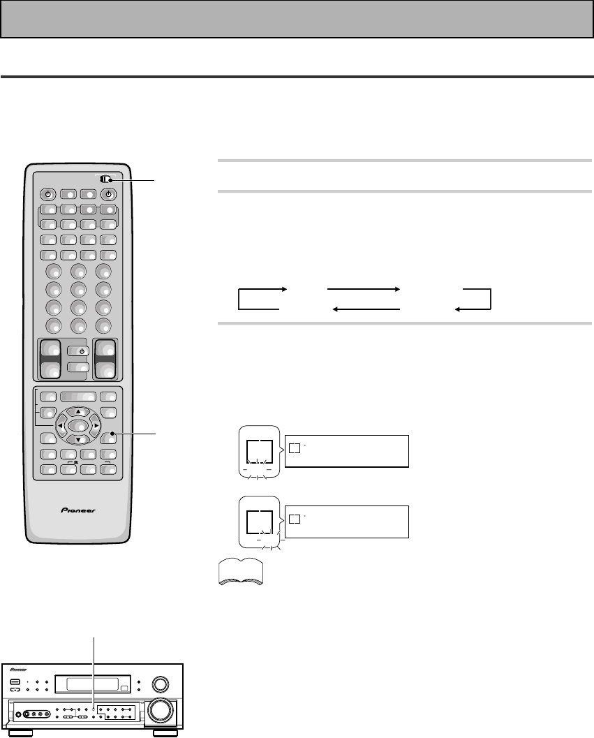
48
En
Switching Analog and Digital Signal Input
This switch moves the input fed to the receiver between analog, digital and 2 RF sources. You need to take
special care to switch to the appropriate input, when necessary. For example, the switch would have to be on
DIGITAL to use DOLBY DIGITAL, DTS or MPEG surround sound but it would have to be on ANALOG to record
to the analog out jacks on the receiver. The default setting is AUTO (priority is given to a digital signal, if there is
one).
1 Put the remote control slide switch in USE.
2 Press the SIGNAL SELECT button to select
the input signal corresponding to the
source component.
Each press switches the signal in the order below:
AUTO ANALOG
AC-3RF DIGITAL
3 When SIGNAL SELECT is set to DIGITAL,
AC-3 lights when a Dolby Digital signal is
input, and DTS lights when a DTS signal is
input.
SIGNAL
SELECT
DTS
SP A
DIGITAL
SIGNAL
SELECT
AC-3
SP A
DIGITAL
SIGNAL
SELECT
DTS
DIGITAL
SIGNAL
SELECT
AC-3
DIGITAL
• In the AUTO setting, SIGNAL SELECT chooses the signal,
based on availability, in the following order: AC-3 RF, DIGITAL,
ANALOG.
• If all the Digital In Select (see p.32) choices are set to OFF, the
SIGNAL SELECT will default to ANALOG.
• Because the audio from a karaoke microphone and LDs
recorded with analog audio only is not output from the digital
output, set SIGNAL SELECT to ANALOG to listen to these
formats.
• This receiver can only play back Dolby Digital, PCM (32kHz,
44kHz, 48kHz, and 96kHz), and DTS and MPEG digital signal
formats. It cannot play back digital signals other than these so
for those kinds of formats you'll have to play them back in an
analog manner (making sure your equipment is hooked up with
analog connections and setting the SIGNAL SELECT to ANA-
LOG).
• When an LD or CD with DTS is played back with the SIGNAL
SELECT set in ANALOG, digital noise caused by playing back
the DTS directly (with no decoding) is output. To prevent noise,
you need to make digital connections (See p.13,14) and set
SIGNAL SELECT to AUTO.
• Some DVD players don’t output DTS and/or MPEG signals. For
more details, refer to the instruction manual supplied with your
DVD player.
memo
When a Dolby Digital
signal is input.
When a DTS signal is
input.
AV PRE-PROGRAMMED AND LEARNING
REMOTE CONTROL UNIT
1
2
/DTS/MPEG
S0URCE
DVD/LD TV/SAT VCR1 VCR2
CD
TV VOL
TV FUNC
MENU
ENTER
STEREO/
DIRECT
DSP
THXLIGHT
MUTE
TV
VOLUME
MD/
TAPE1 TUNER TVCONT
RECEIVER
USE SETUP
MULTI
OPERATION
CLASS MPX
DIRECT ACCESS
CHANNEL
STATION
TUNING
DISPLAY
RF ATT
TV CONTROL
FUNCTION
REMOTE SETUP
SYSTEM SETUP
INPUT
ATT
ADVANCED
MIDNIGHT
MULTI CH
INPUT
STANDARD
DIGITAL
NR
EFFECT/
CH SEL
SIGNAL
SELECT
BAND
SYSTEM
OFF
123
456
789
0
DISC
Î
¶ 873
1¡4¢
+
-
+
-
+
-
MULTI CONTROL
++
––
+
–
+10
2
Basic Playback
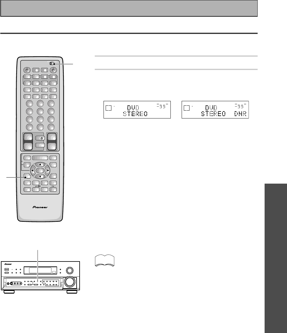
OPERATION
49
En
1 Put the remote control slide switch in USE.
2 Press the DIGITAL NR button on the remote
control or on the front panel.
Each press switches DIGITAL NR on or off.
dB
STEREO
SIGNAL
SELECT
SP A
DIGITAL
VOLUME
j
dB
STEREO
SIGNAL
SELECT
SP A
DIGITAL
VOLUME
• In cases described below, noises may not be reduced even if
DIGITAL NR is on.
• Sudden noise
• Extremely loud noise
• Signals that do not contain many high frequencies
• DIGITAL NR is effective at and above levels shown below for
each source.
• STEREO (excluding 96 kHz)
• analog input ...................................................... 10 -18 dB
• digital input....................................................... 10 -15 dB
• AM/FM tuner ................................................... 10 -15 dB
• DSP/ADVANCED/STANDARD/96 kHz stereo ..... 6 -10 dB
• Depending on the condition of the source, there may not be a
noticeable improvement in the quality of the sound.
Reducing Noise During Playback
To reduce extraneous noise switch on DIGITAL NR. This noise reduction can be used with every mode except
THX and MULTI CH IN.
AV PRE-PROGRAMMED AND LEARNING
REMOTE CONTROL UNIT
/DTS/MPEG
S0URCE
DVD/LD TV/SAT VCR1 VCR2
CD
TV VOL
TV FUNC
MENU
ENTER
STEREO/
DIRECT
DSP
THXLIGHT
MUTE
TV
VOLUME
MD/
TAPE1 TUNER TVCONT
RECEIVER
USE SETUP
MULTI
OPERATION
CLASS MPX
DIRECT ACCESS
CHANNEL
STATION
TUNING
DISPLAY
RF ATT
TV CONTROL
FUNCTION
REMOTE SETUP
SYSTEM SETUP
INPUT
ATT
ADVANCED
MIDNIGHT
MULTI CH
INPUT
STANDARD
DIGITAL
NR
EFFECT/
CH SEL
SIGNAL
SELECT
BAND
SYSTEM
OFF
123
456
789
0
DISC
Î
¶ 873
1¡4¢
+
-
+
-
+
-
MULTI CONTROL
++
––
+
–
+10
1
2
2
Basic Playback
• You can’t use the DIGITAL NR mode with the THX or MULTI
CH IN modes.
• If you press DIGITAL NR when in DIRECT mode the receiver
switches to STEREO mode.
memo
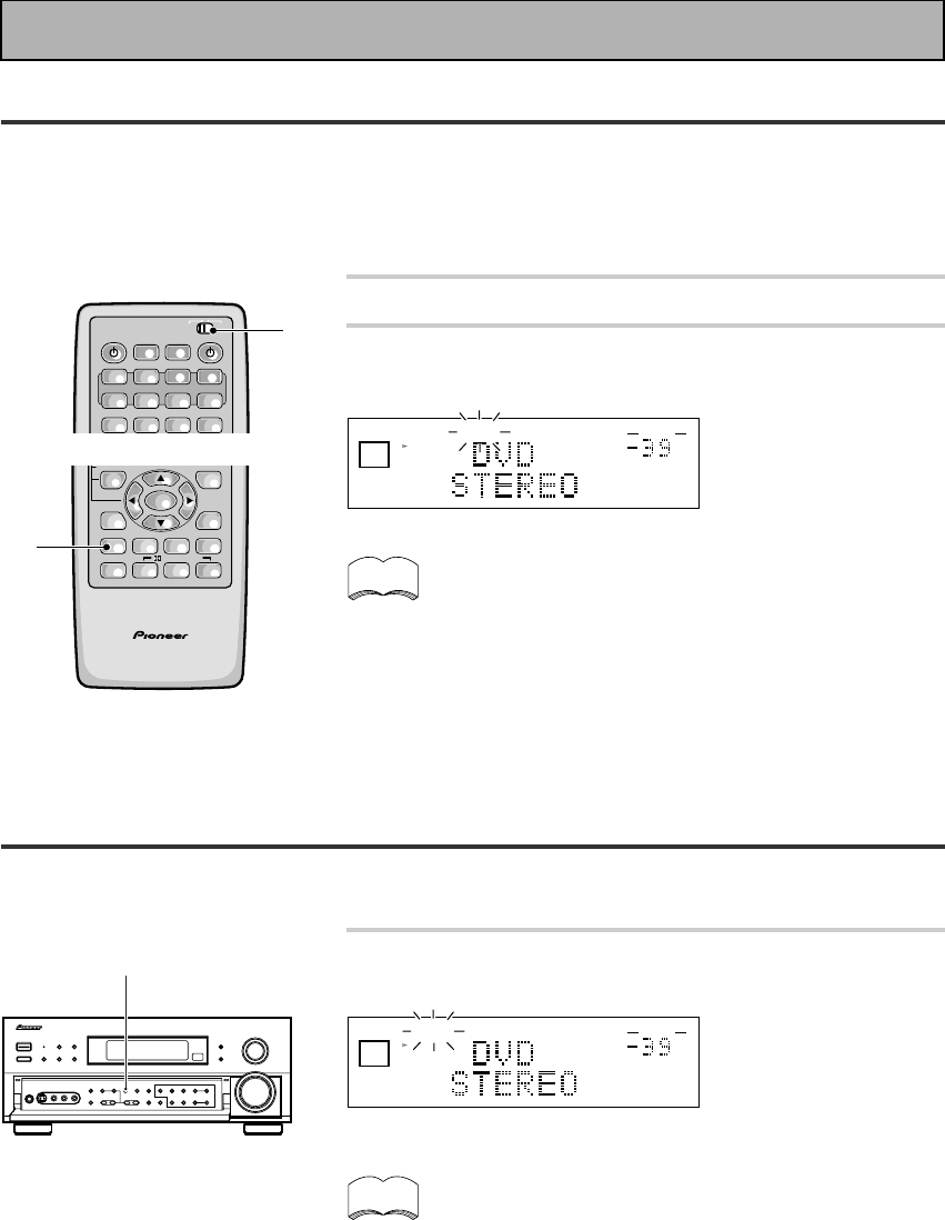
50
En
Listening the Loudness Mode
The LOUDNESS mode allows you to boost the bass and treble in a signal. It is useful for listening to music at
low volumes.
dB
STEREO
LOUDNESSSIGNAL
SELECT
ANALOG
SP A
AUTO
VOLUME
Press the LOUDNESS button.
Each press switches LOUDNESS mode between on and off.
• You can’t use the LOUDNESS mode with the MULTI CH IN
or THX modes.
• If you press LOUDNESS in DIRECT mode the receiver will
switch to STEREO mode.
memo
LOUDNESS
Listening in Midnight Mode
This feature makes it possible to get excellent surround sound effects even when listening at low volumes. It
can be used with a variety of surround sound sources and plays soundtracks so that the quieter sounds are
audible while the noisier sounds don’t become overly loud or distorted. It does this by bringing all the sounds in
a given soundtrack closer together in volume. Compare this feature with the D-Range Control (only for Dolby
Digital sources) on page 40.
1 Put the remote control slide switch in USE.
2 Press the MIDNIGHT button.
Each press switches MIDNIGHT LISTENING mode on or off.
• The effect adjusts itself automatically in accordance with
the volume level.
• You can’t use the MIDNIGHT LISTENING mode with the
THX or MULTI CH IN modes.
• If you use MIDNIGHT in DIRECT mode the receiver will
switch to STEREO mode.
memo
dB
STEREO
MIDNIGHTSIGNAL
SELECT
SP A
DIGITAL
AUTO
VOLUME
Basic Playback
S0URCE
DVD/LD TV/SAT VCR1 VCR2
CD MD/
TAPE1 TUNER TVCONT
RECEIVER
USE SETUP
MULTI
OPERATION
CLASS MPX
DIRECT ACCESS
BAND
SYSTEM
OFF
Î
¶ 873
MULTI CONTROL
1
AV PRE-PROGRAMMED AND LEARNING
REMOTE CONTROL UNIT
/DTS/MPEG
ENTER
STEREO/
DIRECT
DSP
THXLIGHT
FUNCTION
SYSTEM
SETUP
ADVANCED
MIDNIGHT
MULTI CH
INPUT
STANDARD
DIGITAL
NR
EFFECT/
CH SEL
SIGNAL
SELECT
+
–
2
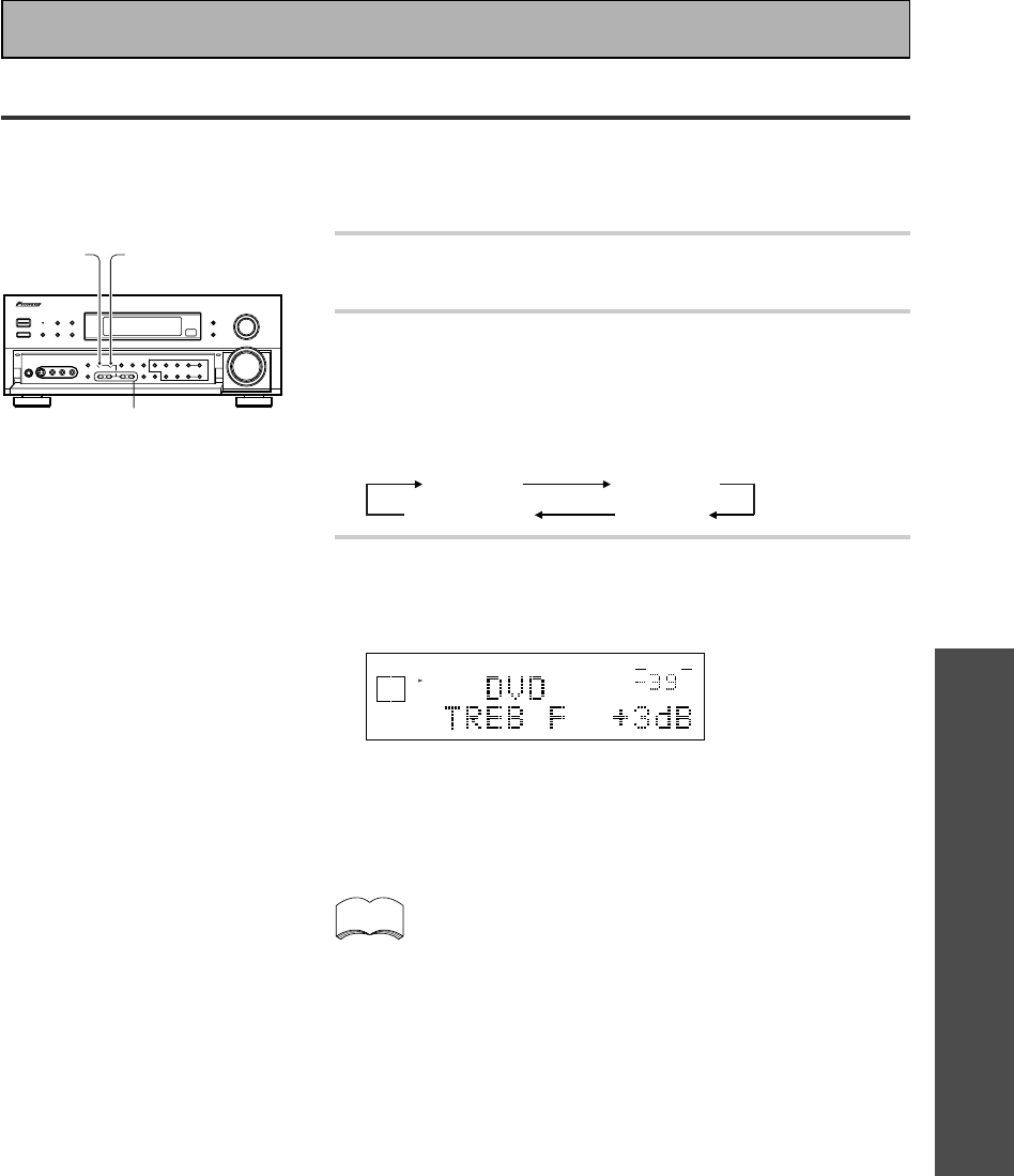
OPERATION
51
En
Basic Playback
Adjusting Bass and Treble
You can use BASS +/– or TREBLE +/– buttons to adjust the low and high frequencies for each individual set of
speakers. If the receiver is in STEREO mode you can only adjust the FRONT speakers. In a surround mode
(STANDARD, ADVANCED THEATER, etc.) you can adjust the FRONT, CENTER, SURROUND and SURROUND
BACK speakers. The TONE button can also be used to bypass the tone circuitry (see p.27).
1 Press the TONE button on the front panel to
put the receiver in tone on mode.
2 Press the CHANNEL SELECT button on the
front panel to cycle through the different
tone adjust modes.
The button cycles though the possibilities in the following
order:
TONE Front TONE Center
TONE SurBack TONE Surr.
3 Use the BASS or TREBLE (+/–) buttons to
adjust the low or high frequencies of each
channel.
dB
STEREO
SIGNAL
SELECT
ANALOG
SP A
VOLUME
A few seconds after you finish adjusting the tone the receiver will
revert to the sound mode it was in at the beginning of the
process.
• The tone control can be adjusted in a range of ±6 dB.
• The tone control cannot be adjusted in THX and MULTI CH
IN modes.
• If the receiver is in DIRECT mode and you press the TONE
button, TONE BYPASS will appear in the display, letting you
know that you can't change the tone in DIRECT mode. An-
other press cancels DIRECT mode.
memo
2
3
1
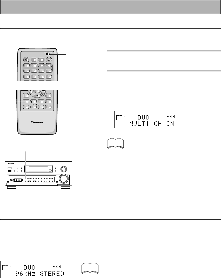
52
En
Basic Playback
MULTI CHANNEL IN Playback
MULTI CH IN allows you to connect an external decoder to enjoy certain types of specialized discs. To use
MULTI CH IN playback follow the instructions below.
memo
1 Put the remote control slide switch
in USE.
2 Press the MULTI CH INPUT button
on the remote control or the front
panel.
Each press switches the input between the previous
mode and MULTI CH IN.
dB
SIGNAL
SELECT
ANALOG
SP A
VOLUME
When MULTI CH IN is used in BYPASS mode
only the volume level can be set. All of this unit’s
other features (DIGITAL NR etc.) cannot be used.
Also, all speaker settings and other setup set-
tings have no effect.
2
96kHz 24bit Performance
This receiver is capable of playing back advanced DVD discs which are recorded in 96 kHz/24 bit format (these
are all stereo discs) and any source recorded in 96 kHz and up to 24 bit. The receiver will automatically read the
format of the source and play accordingly (of course the SIGNAL SELECT will have to set to AUTO or DIGITAL
to read the DVD soundtrack). When the receiver plays a 96 kHz disc ”96 kHz” and whatever mode you're using
(for example ”STEREO,” ”DIRECT or DNR”) will appear in the display.
dB
STEREO
SIGNAL
SELECT
SP A
DIGITAL
AUTO
VOLUME
memo • When a 96 kHz/24 bit disc is played back the volume
may be louder than that of a normal disc.
• Some DVD players cannot play 96 kHz/24 bit discs.
Check the manual of your DVD player to make sure.
• During this playback the player enters the STEREO
mode and you can use the controls available in
STEREO mode (LOUDNESS, MIDNIGHT, TONE
controls, etc., see p.50-51).
• With 96 kHz/24 bit discs you are able to use MULTI
CH IN playback and the TAPE 2 MONITOR.
• In 96 kHz/24 bit mode you can't use the STANDARD,
ADVANCED THEATER, THX, or DSP modes.
S0URCE
DVD/LD TV/SAT VCR1 VCR2
CD MD/
TAPE1 TUNER TVCONT
RECEIVER
USE SETUP
MULTI
OPERATION
CLASS MPX
DIRECT ACCESS
STATION
TUNING
BAND
SYSTEM
OFF
Î
¶ 873
+
-
+
-
MULTI CONTROL
1
AV PRE-PROGRAMMED AND LEARNING
REMOTE CONTROL UNIT
/DTS/MPEG
ENTER
STEREO/
DIRECT
DSP
THXLIGHT
ADVANCED
MIDNIGHT
MULTI CH
INPUT
STANDARD
DIGITAL
NR SIGNAL
SELECT
–
2
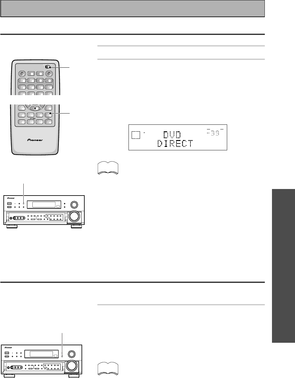
OPERATION
53
En
Adjusting the Brightness of the Display
Use the FL DIMMER button to adjust the brightness of the fluorescent display (FL=fluorescent display).
Press the FL DIMMER button.
Four levels of brightness ranging from very dim to very bright can
be selected. Each press changes the brightness of the display.
When rotating through the options, the default brightness can also
be selected.
Please note: it is a feature of this unit that the fluorescent
display will be brighter for a few seconds after you choose a
function (like DVD/LD, CD, etc.) and then get softer. This will
still happen when you adjust the brightness but the new set-
ting will be the one the display softens to.
memo
Direct Playback
This mode is for playing back a sound source in its purest form, no tone adjustments or other sound modes can
be used.
1 Put the remote control slide switch in USE.
2 Use the STEREO/DIRECT button to alternate
between STEREO or DIRECT mode (you can
also use the STEREO/DIRECT button on the
front panel).
The DIRECT mode will give you the most accurate reproduction of
two channel (stereo) sources but won't let you add any effects to
the sound.
• None of the tone controls or other sound modes can be
used with DIRECT playback.
• If the receiver is in a different mode than STEREO to start
with the first push of the STEREO button will put it in STE-
REO mode. After that the button will toggle the receiver
between STEREO and DIRECT mode.
• For more on this button see the explanation of STEREO
mode on p.44, 45, 47.
memo
FL DIMMER
STEREO/
DIRECT
S0URCE
DVD/LD TV/SAT VCR1 VCR2
CD MD/
TAPE1 TUNER TVCONT
RECEIVER
USE SETUP
MULTI
OPERATION
CLASS MPX
DIRECT ACCESS
BAND
SYSTEM
OFF
Î
¶ 873
MULTI CONTROL
1
Basic Playback
dB
STEREO
SIGNAL
SELECT
ANALOG
SP A
VOLUME
AV PRE-PROGRAMMED AND LEARNING
REMOTE CONTROL UNIT
/DTS/MPEG
STEREO/
DIRECT
DSP
THXLIGHT
ADVANCED
MIDNIGHT
MULTI CH
INPUT
STANDARD
DIGITAL
NR SIGNAL
SELECT
–
2
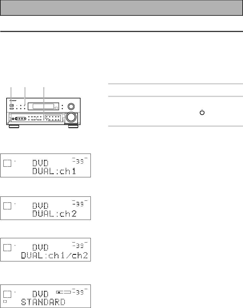
54
En
DUAL MONO Setting
The dual mono setting can only be used when listening to Dolby Digital discs that have dual mono software
encoded in them. Dual mono software usually is used to put two different soundtracks on one DVD. With this
setting you can choose which channel in the dual mono setting you want to listen to. Thus, it is useful for
soundtracks that have one language on one channel and a different language on the other. Remember this
setting is only applicable if you are using Dolby Digital software with dual mono and want to isolate one of the
channels therein. Otherwise, just ignore this function.
.
1 Put the receiver in STANDBY mode.
2 While holding down the VIDEO
SELECT button press the STANDBY/
ON button on the front panel.
3 You will see DUAL in the display for
about five seconds. During this time
use the STEREO/DIRECT button to
cycle through the different DUAL
MONO settings to find the one you
want.
The different settings are: DUAL ch1, where you only
hear channel 1; DUAL ch2, where you only hear channel
2; and DUAL ch1/ch2, where you hear both channels, but
independently from different speakers.
The default setting is DUAL ch1.
dB
STEREO
SIGNAL
SELECT
ANALOG
SP A
VOLUME
DUAL ch1 setting
dB
STEREO
SIGNAL
SELECT
ANALOG
SP A
VOLUME
dB
STEREO
SIGNAL
SELECT
ANALOG
SP A
VOLUME
DUAL ch2 setting
DUAL ch1/ch2 setting
32
1,2
Basic Playback
When DUAL MONO is
playing with ch 1 selected
the L will Lights. When
playing with ch 2 selected
the R will Lights. When
playing with ch 1/2 selected
the L and R will Lights.
DIGITAL
dB
SIGNAL
SELECT
AC-3
SP A
L
DIGITAL
VOLUME
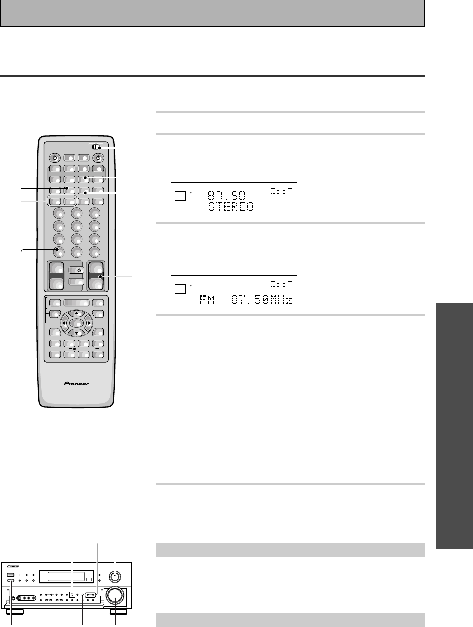
OPERATION
55
En
Automatic and Manual Tuning
The following steps show you how to tune in FM and AM radio broadcasts using the automatic (search) and
manual (step) tuning functions. If you already know the exact frequency of the station you desire, see “Direct
Access Tuning“ on the following page.
1 Put the remote control slide switch in USE.
2 Press the TUNER button.
On the remote, this selects the TUNER function on the receiver
and sets the remote to the TUNER operation mode.
dB
STEREO
SIGNAL
SELECT
ANALOG
SP A
FM
VOLUME
3 Press BAND button on the remote control or
the front panel to select the band (FM or AM).
Each press switches the band: FM j AM
dB
STEREO
SIGNAL
SELECT
ANALOG
SP A
VOLUME
4 Tune in the station.
For Automatic Tuning
Press and hold TUNING –/+ buttons for about one second, then
release.
The tuner starts searching the selected band and stop automat-
ically at the first station it locates. Repeat to locate other
stations.
For Manual Tuning
• To change frequencies one step at a time, press TUNING –/+
buttons repeatedly.
• To change frequencies quickly, hold down TUNING –/+
buttons and release when you reach the frequency you
desire.
5 Adjust the MASTER VOLUME buttons on
the remote control or the MASTER VOLUME
on the front panel.
MPX Mode
If the TUNED or STEREO indicators do not light when tuning an FM station,
because the station is too far away or the broadcast signal is weak, press
MPX button on the remote control to switch to MONO reception. This
should improve reception enough for you to enjoy the broadcast.
RF ATT Mode
Press the RF ATT button to turn the RF attenuator on to reduce sound
distortion when receiving strong FM signals from nearby stations.
Normally, this button should be set to off. This button does not affect
AM reception.
42
5
3
RF ATT
_ON/—OFF
button
AV PRE-PROGRAMMED AND LEARNING
REMOTE CONTROL UNIT
/DTS/MPEG
S0URCE
DVD/LD TV/SAT VCR1 VCR2
CD
TV VOL
TV FUNC
MENU
ENTER
STEREO/
DIRECT
DSP
THXLIGHT
MUTE
TV
VOLUME
MD/
TAPE1 TUNER TVCONT
RECEIVER
USE SETUP
MULTI
OPERATION
CLASS MPX
DIRECT ACCESS
CHANNEL
STATION
TUNING
DISPLAY
RF ATT
TV CONTROL
FUNCTION
REMOTE SETUP
SYSTEM SETUP
INPUT
ATT
ADVANCED
MIDNIGHT
MULTI CH
INPUT
STANDARD
DIGITAL
NR
EFFECT/
CH SEL
SIGNAL
SELECT
BAND
SYSTEM
OFF
123
456
789
0
DISC
Î
¶ 873
1¡4¢
+
-
+
-
+
-
MULTI CONTROL
++
––
+
–
+10
1
2
3
MPX
RF ATT
5
4
Using the Tuner
Before operating the receiver, be sure to press the _ ON/ — OFF button on the front panel to turn the
power ON (_).
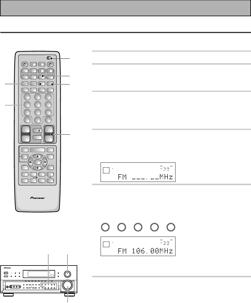
56
En
Direct Access Tuning
The following steps show you how to tune directly to a specific frequency using the remote control.
1 Put the remote control slide switch in USE.
2 Press the TUNER button.
This selects the TUNER function on the receiver and sets the
remote to the TUNER operation mode.
3 Press the BAND button on the remote
control or the front panel to select the band
(FM or AM).
Each press switches the band : FM j AM
4 Press DIRECT ACCESS button to activate
the direct Access tuning mode.
The cursor blinks in the display on the front panel.
dB
STEREO
SIGNAL
SELECT
ANALOG
SP A
VOLUME
5 Use the number buttons to enter the
frequency of the station you want.
Example:
To tune station 106.00 (FM), press:
1 =
0
=6 =0 =
0
dB
STEREO
SIGNAL
SELECT
ANALOG
SP A
STEREO
TUNED
VOLUME
To cancel before inputting the frequency
Press DIRECT ACCESS button, and enter the frequency again.
6 Adjust the MASTER VOLUME buttons on
the remote control or the MASTER VOLUME
on the front panel.
AV PRE-PROGRAMMED AND LEARNING
REMOTE CONTROL UNIT
/DTS/MPEG
S0URCE
DVD/LD TV/SAT VCR1 VCR2
CD
TV VOL
TV FUNC
MENU
ENTER
STEREO/
DIRECT
DSP
THXLIGHT
MUTE
TV
VOLUME
MD/
TAPE1 TUNER TVCONT
RECEIVER
USE SETUP
MULTI
OPERATION
CLASS MPX
DIRECT ACCESS
CHANNEL
STATION
TUNING
DISPLAY
RF ATT
TV CONTROL
FUNCTION
REMOTE SETUP
SYSTEM SETUP
INPUT
ATT
ADVANCED
MIDNIGHT
MULTI CH
INPUT
STANDARD
DIGITAL
NR
EFFECT/
CH SEL
SIGNAL
SELECT
BAND
SYSTEM
OFF
123
456
789
0
DISC
Î
¶ 873
1¡4¢
+
-
+
-
+
-
MULTI CONTROL
++
––
+
–
+10
1
2
4
3
6
5
Using the Tuner
3 2
6
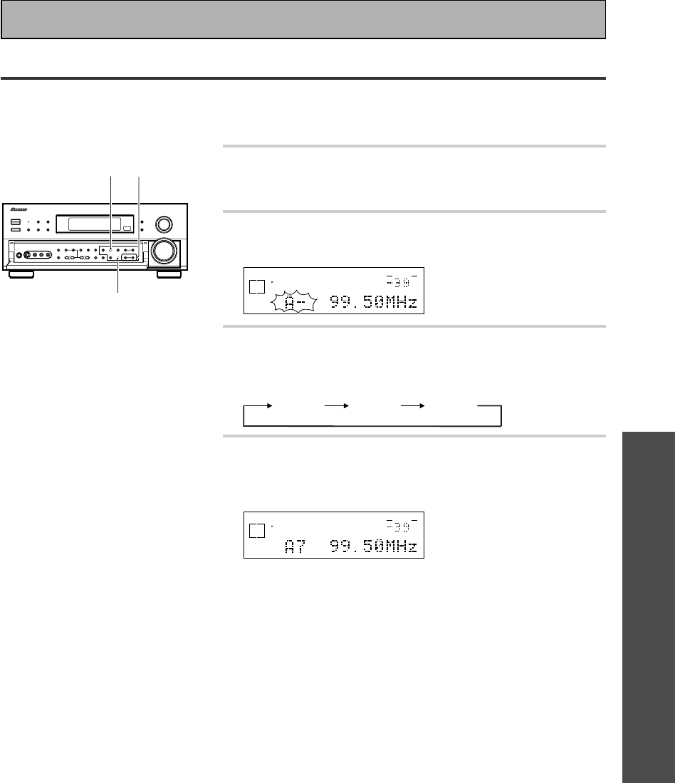
OPERATION
57
En
Memorizing Frequently Used Stations
The following steps show you how to memorize up to 30 radio stations in 3 classes (each holding 10 channels).
When memorizing FM frequencies, the receiver also memorizes the MPX mode (STEREO or MONO and RF
ATT).
1 Tune in the desired station.
See ”Automatic and Manual Tuning” or ”Direct Access Tuning”
on p.55 and 56.
2 Press the MEMORY button to activate the
memory function.
dB
STEREO
SIGNAL
SELECT
ANALOG
SP A
STEREO
TUNED
VOLUME
3 Press the CLASS button repeatedly to select
a class number.
Each press switches the display:
CLASS A CLASS B CLASS C
4 Press the STATION –/+ buttons repeatedly
to select a channel (0-9) within the
respective class.
dB
STEREO
SIGNAL
SELECT
ANALOG
SP A
STEREO
TUNED
VOLUME
The station is memorized automatically after 5 seconds.
If you want to escape from MEMORY mode
Press the MEMORY button again.
Repeat steps 1 through 4 to memorize up to 30 stations.
43
2
Using the Tuner
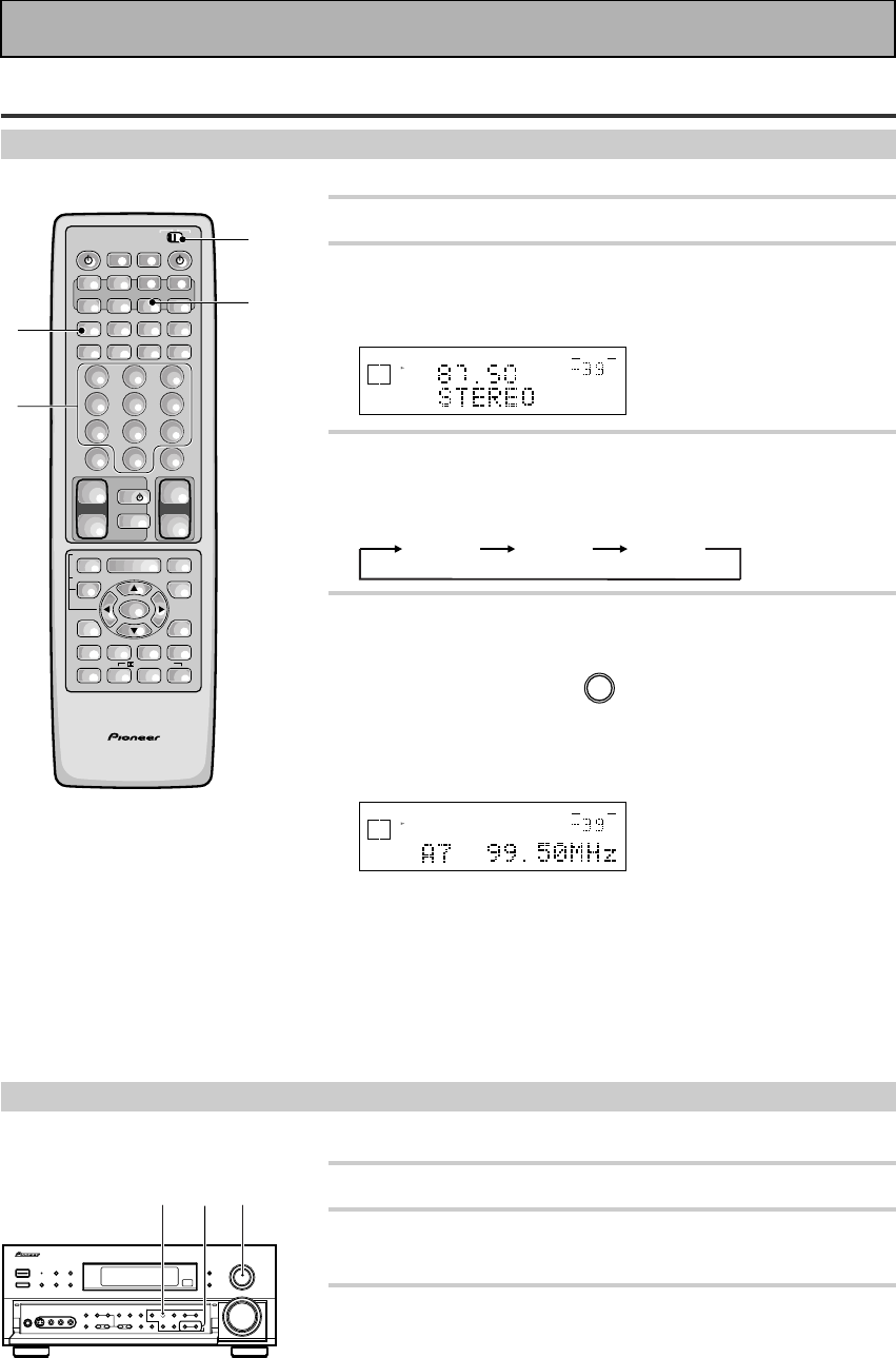
58
En
Recalling Memorized Stations
Using the remote control
1 Put the remote control slide switch in USE.
2 Press the TUNER button.
This selects the TUNER function on the receiver and sets the
remote to the TUNER operation mode.
dB
STEREO
SIGNAL
SELECT
ANALOG
SP A
FM
VOLUME
3 Press the CLASS button repeatedly to select
a class number.
Each press switches the display:
CLASS A CLASS B CLASS C
4 Use the number buttons to select the
channel you want.
To select channel 7, press 7.
For example : If 99.50 MHz (FM) was memorized in class A at
channel 7.
dB
STEREO
SIGNAL
SELECT
ANALOG
SP A
STEREO
TUNED
VOLUME
To skip through each channel in order
Press STATION –/+ repeatedly.
Using the front panel
1 Select the TUNER function.
2 Press the CLASS button repeatedly to select
a class number.
3 Press the STATION –/+ buttons repeatedly
to select the channel you want.
AV PRE-PROGRAMMED AND LEARNING
REMOTE CONTROL UNIT
/DTS/MPEG
S0URCE
DVD/LD TV/SAT VCR1 VCR2
CD
TV VOL
TV FUNC
MENU
ENTER
STEREO/
DIRECT
DSP
THXLIGHT
MUTE
TV
VOLUME
MD/
TAPE1 TUNER TVCONT
RECEIVER
USE SETUP
MULTI
OPERATION
CLASS MPX
DIRECT ACCESS
CHANNEL
STATION
TUNING
DISPLAY
RF ATT
TV CONTROL
FUNCTION
REMOTE SETUP
SYSTEM SETUP
INPUT
ATT
ADVANCED
MIDNIGHT
MULTI CH
INPUT
STANDARD
DIGITAL
NR
EFFECT/
CH SEL
SIGNAL
SELECT
BAND
SYSTEM
OFF
123
456
789
0
DISC
Î
¶ 873
1¡4¢
+
-
+
-
+
-
MULTI CONTROL
++
––
+
–
+10
1
2
3
4
32 1
Using the Tuner
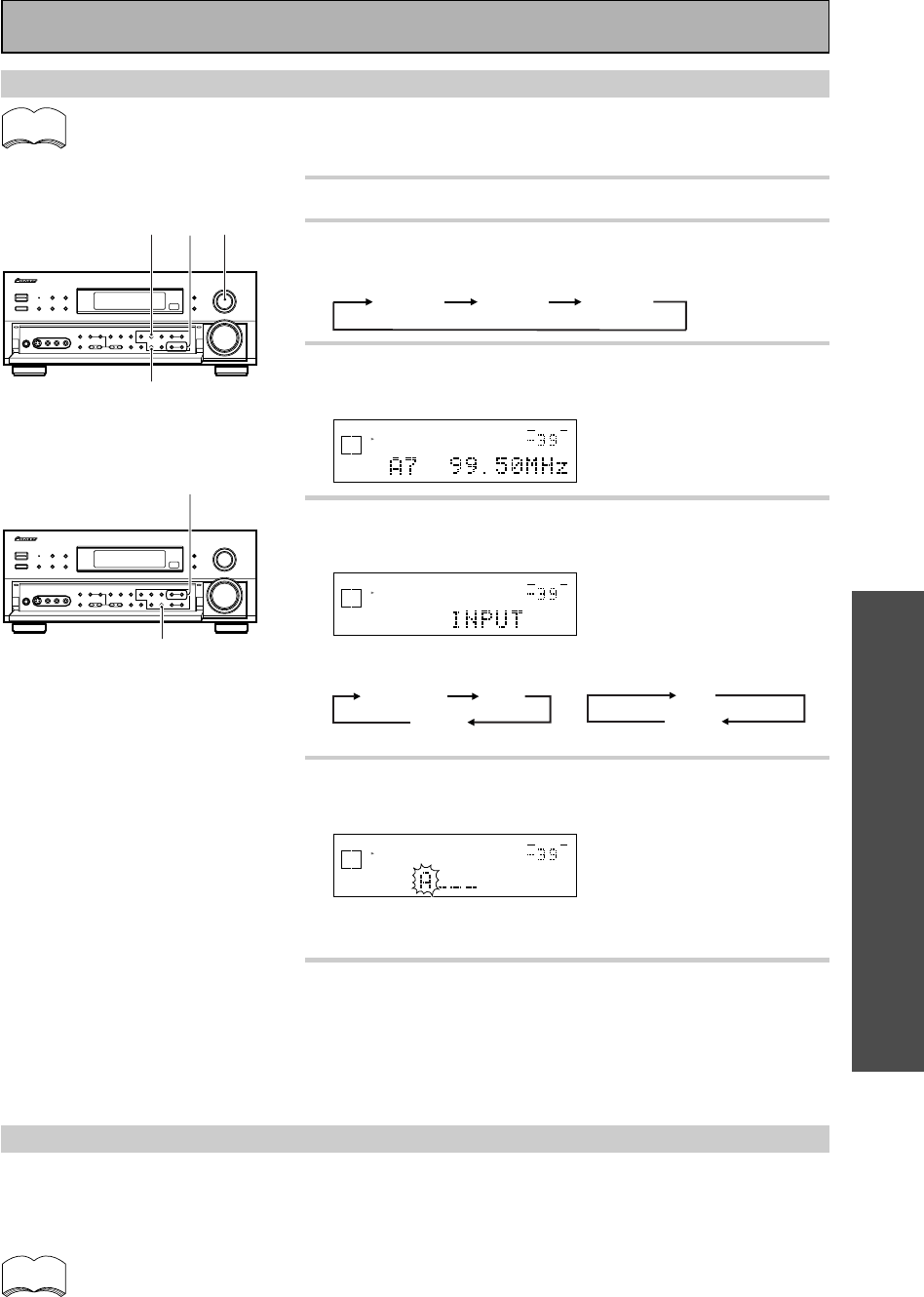
OPERATION
59
En
Memorizing a broadcast station name (Manual Station Name Memory)
• You can input a name of up to four characters for each preset broadcast station (see pages 57).
• The memorized name takes priority over PS data.
1 Select the TUNER function.
2 Press the CLASS button repeatedly to select
a class.
CLASS A CLASS B CLASS C
3 Press the STATION +/– buttons to select the
preset channel.
dB
STEREO
SIGNAL
SELECT
ANALOG
SP A
STEREO
TUNED
VOLUME
4 Press the CHARACTER/SEARCH button to
select the character input mode.
dB
STEREO
SIGNAL
SELECT
ANALOG
SP A
STEREO
TUNED
VOLUME
When FM is selected:
INPUT
(Character input mode)
OFFSEARCH
5 Press the TUNING +/– buttons to enter the
broadcast station name.
dB
STEREO
SIGNAL
SELECT
ANALOG
SP A
STEREO
TUNED
VOLUME
Refer to “Character display used for station name input” on
p.87.
6 Press MEMORY to input the first of four
characters. After four characters have been
entered, the character input mode is exited.
Repeat steps 2 to 4 to memorize up to 30 broadcast station
names.
* When it is set to OFF,
frequency being received
will be displayed.
To erase and change the memorized station name
Perform the procedures of “Memorizing a broadcast station name” and enter four spaces to erase the
memorized station name.
When you want to change a memorized station name, input the new station name using the same procedure.
For greater convenience, record memorized station names in the STATION CALL button “memo” on
p.87.
When AM is selected:
INPUT
(Character input mode)
OFF
32 1
4
5
6
memo
memo
Using the Tuner

60
En
Current affairs
General information
Educational material
Radio plays or serials
Science and technology
Usually talk-based material, such as quiz shows or interviews.
Pop music
Rock music
“Middle of the road” music
‘Light’ classical music
‘Serious’ classical music
Other music not fitting any of the above categories
Stock market reports, commerce, trading, etc.
Children’s entertainment
Social affairs
Holiday-type travel rather than traffic announcements.
Leisure interests and hobbies
Country music
Popular music in a language other than English
Popular music from the ’50s
Folk music
Documentaries
An Introduction to RDS & EON
Radio Data System, or RDS as it's usually known, is a system used by FM radio stations to provide listeners
with various kinds of information—the name of the station and the kind of show they're broadcasting, for
example. This information shows up as text on the display, and you can switch between the kind of information
shown. Although you don't get RDS information from all FM radio stations, you do with most.
Probably the best feature of RDS is that you can search automatically by type of program. So, if you felt like
listening to jazz, you could search for a station that's broadcasting a show with the program type, ”JAZZ”. There
are around 30 such program types, including various genres of music, news, sport, talk shows, financial
information, and so on.
The VSX-909RDS/909RDS-G receiver lets you display three different kinds of RDS information: Radio Text,
Program Service Name, and Program Type.
Radio Text (RT) is messages sent by the radio station. These can be anything the broadcaster chooses—a talk
radio station might give out it telephone number as RT, for example.
Program Service Name (PS) is the name of the radio station.
Program Type (PTY) indicates the kind of program currently being broadcast.
The VSX-909RDS can search for and display the following program types:
In addition, there is a program type, ALARM!, used for exceptional emergency announcements. You can't
search for this, but the tuner will switch automatically to this RDS broadcast signal.
Using the Tuner
NEWS
AFFAIRS
INFORMATION
SPORT
EDUCATION
DRAMA
CULTURE
SCIENCE
VARIED
POP MUSIC
ROCK MUSIC
M.O.R. MUSIC
Light MUSIC
CLASSICAL
Other MUSIC
WEATHER
FINANCE
CHILDREN
SOC AFFAIRS
RELIGION
PHONE IN
TRAVEL
LEISURE
JAZZ MUSIC
COUNTRY M
NATIONAL M
OLDIES MUSIC
FOLK MUSIC
DOCUMENTARY

OPERATION
61
En
Basics of EON
EON (Enhanced Other Network information)
EON is a function that allows you to set the receiver to switch to a frequency automatically when a program
featuring traffic information or news is being broadcast. It cannot be used in areas that EON information is not
transmitted and when FM broadcast stations do not transmit PTY data. When the broadcast ends, the tuner
returns to the original frequency or function.
There are two types of EON you can set the tuner to:
1. TA (Traffic Announcement)
This mode will set the tuner to pick up traffic information when it is broadcast.
2. NEWS
This mode will set the tuner to pick up news when it is broadcast.
Setting EON allows automated reception of TA/NEWS broadcasts
When EON is turned on, the receiver will automatically jump to those EON-linked broadcasts. Even if a receiver
function other than the tuner is being used, the receiver function will switch to the FM station automatically
when an EON-linked Traffic Information or News program begins. When the program ends, the original function
will be restored. The EON function will not operate, however, when the tuner is on AM.
The receiver’s internal Program Identification function
PI (Programma Identification)
This is an identifying marker the tuner automatically attaches to stations stored in your preset memory classes
(see p.59). The marker distinguishes between stations which transmit RDS data and those that don’t, so that the
receiver knows which stations to look at when searching for RDS or EON transmissions. The code is not
displayed on the receiver and you don’t need to do anything in regards to setting the PI codes.
PI code registration and erasure
The receiver will automatically register a PI code for any station you input into the memory classes (see p.59)
which can receive RDS or EON data. If you want to have a station preset in your memory banks but DON’T want
the receiver to search this station for RDS information you can erase the PI code and then the receiver will
ignore this station when searching for RDS transmissions.
To erase PI codes, follow this procedure:
1. When tuned to the station whose PI code you want to erase press the EON MODE button for two seconds
or more.
“ERASE PI” will be displayed.
2. Press MEMORY button within 5 seconds.
Using the Tuner
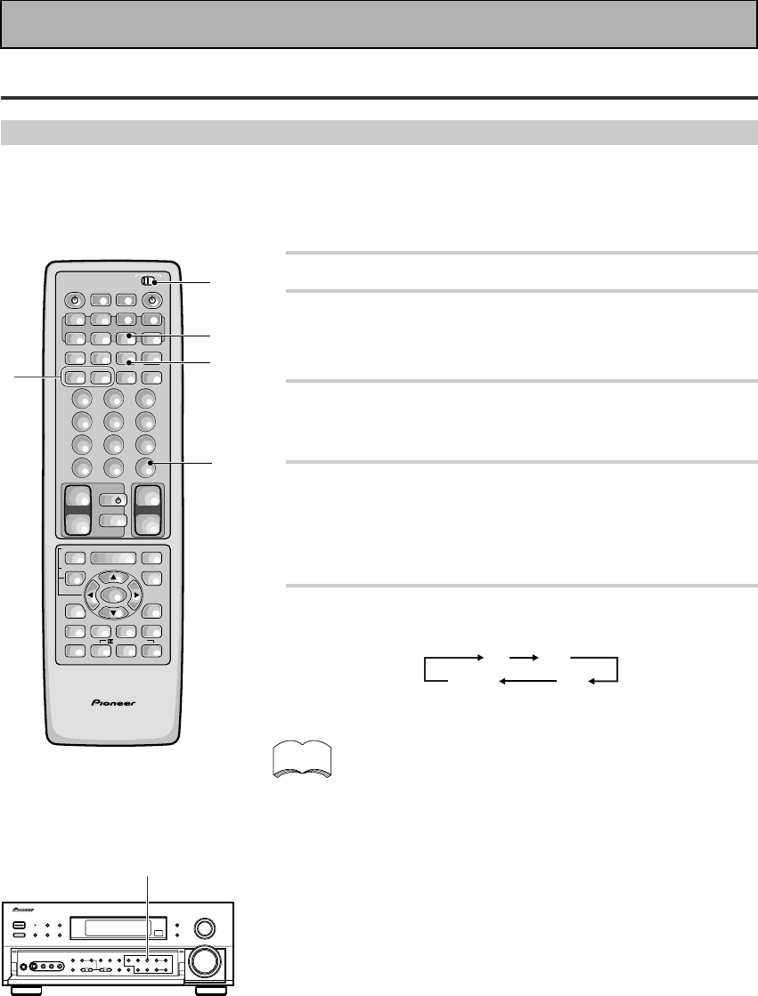
62
En
RDS (Radio Data System) Broadcast Reception
Displaying RDS data
One of the most useful features of RDS is the ability to search for a particular kind of radio program. You can
search for any of the program types listed on page 60—this covers all kinds of music, as well as news, weather
forecasts, sports programs, and a variety of others.
memo
1 Put the remote control slide switch in USE.
2 Press the TUNER button.
This selects the TUNER function on the receiver and sets the
remote control to the TUNER operation mode.
The previously tuned station is received automatically.
3 Press the BAND button on the remote
control or the front panel to select FM.
Each press switches the band: FM j AM
4 Tune into a station.
Refer to “Automatic and Manual Tuning” or “Direct Access
Tuning” on pages 55 and 56.
• If the received broadcast transmits RDS data, the RDS indica-
tor lights, and the data of the display mode appears in the
display.
5 Press the DISPLAY button to select a mode.
Each press changes the display as follows:
FREQ
PSRT
PTY
• In the RT mode, should any noise be picked up while
displaying the RT scroll, some characters may temporarily
be incorrectly displayed.
• In the RT mode, when no RT data is transmitted from a
broadcast station, “NO RADIO TEXT DATA” is displayed
once and after that the PS data is displayed.
• In the PTY mode, there are cases where “NO TYPE” is
displayed. In this case, it will automatically switch to the
PS mode after a few seconds.
• When reception conditions are strong, and RDS data is
incorrectly displayed, press RF ATT.
AV PRE-PROGRAMMED AND LEARNING
REMOTE CONTROL UNIT
/DTS/MPEG
S0URCE
DVD/LD TV/SAT VCR1 VCR2
CD
TV VOL
TV FUNC
MENU
ENTER
STEREO/
DIRECT
DSP
THXLIGHT
MUTE
TV
VOLUME
MD/
TAPE1 TUNER TVCONT
RECEIVER
USE SETUP
MULTI
OPERATION
CLASS MPX
DIRECT ACCESS
CHANNEL
STATION
TUNING
DISPLAY
RF ATT
TV CONTROL
FUNCTION
REMOTE SETUP
SYSTEM SETUP
INPUT
ATT
ADVANCED
MIDNIGHT
MULTI CH
INPUT
STANDARD
DIGITAL
NR
EFFECT/
CH SEL
SIGNAL
SELECT
BAND
SYSTEM
OFF
123
456
789
0
DISC
Î
¶ 873
1¡4¢
+
-
+
-
+
-
MULTI CONTROL
++
––
+
–
+10
1
2
3
4
5
Using the Tuner
3
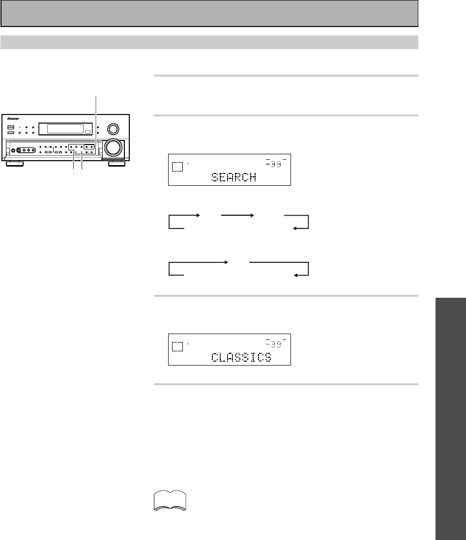
OPERATION
63
En
Searching for a program by program type (PTY)
1 Tune into an FM station.
Refer to “Automatic and Manual Tuning” or “Direct Access
Tuning” on p.55 and 56.
2 Press the CHARACTER/SEARCH button to
select the PTY search mode.
dB
STEREO
SIGNAL
SELECT
ANALOG
SP A
VOLUME
When the STATION mode is selected:
SEARCH (PTY search mode)
INPUTOFF
When the FREQUENCY mode is selected:
SEARCH (PTY search mode)
OFF
3 Press the TUNING +/– buttons to select the
desired program type.
dB
STEREO
SIGNAL
SELECT
ANALOG
SP A
VOLUME
4 Press the MEMORY button to search for the
selected program type.
This will search the preset stations for a station broadcasting the
selected program type. Press the MEMORY button within 5
seconds after a program has been found. If the MEMORY button
is not pressed, the function will begin to search for another
station automatically.
This function searches RDS station preset in the 30ch
memory. If this function is set when no stations have been
preset, “NO PTY” will be displayed. If the desired PTY could
not be found amongst the RDS stations in memory, the same
display appears.
* When it is set to OFF, the
frequency being received is
displayed.
* Refer to page 60 for program
types.
memo
3
42
Using the Tuner
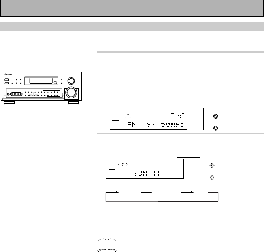
64
En
Using EON search
Refer to p.60 for more information about EON.
1 Tune into an EON FM station.
Refer to “Automatic and Manual Tuning” or “Direct Access
Tuning” on p.55 and 56.
• Even if the EON mode is off, when an FM station is broadcast-
ing a news of traffic information program, the EON indicator
lights in the display to inform you that the currently tuned
station carries the EON data service.
dB
STEREO
SIGNAL
SELECT
ANALOG
SP AEON
RDS
STEREO
TUNED
VOLUME
EON
MODE
FL
DIMMER
2 Press the EON MODE button to select the
mode.
dB
STEREO
SIGNAL
SELECT
ANALOG
SP AEON
RDS
STEREO
TUNED
VOLUME
EON
MODE
FL
DIMMER
Each press changes the display as follows:
EON TA EON NEWS OFF
• When EON is set to OFF, the frequency being received will be
displayed, and then the RDS data will be displayed in the present
display mode.
• The EON mode is canceled if you switch to AM reception while
setting EON. Start once again after you return to FM reception.
• Simultaneous requests for Traffic Information (TA) and News
programs is not possible.
• You cannot operate the MEMORY and CHARACTER/SEARCH
buttons while the EON MODE indicator on the button lights.
• Functions other than TUNER cannot be changed while the EON
MODE indicator on the button blinks (while receiving EON
broadcast). If you want to change to a source other than TUNER,
press the EON MODE button and turn the EON mode off.
• When you are playing back TAPE 2 while setting EON, TAPE 2 will
be canceled by reception of EON. The function returns once more to
TAPE 2 after EON reception is finished.
• When EON is turned on and a function other than the tuner is
selected, the function will switch to the FM station automatically
when Traffic Information or News begins. When the program ends,
the original function will be restored.
• When the EON mode is on, the EON MODE indicator on the button
lights. During reception of the selected news or traffic information
broadcast, the EON MODE indicator on the button blinks.
memo
2
Using the Tuner
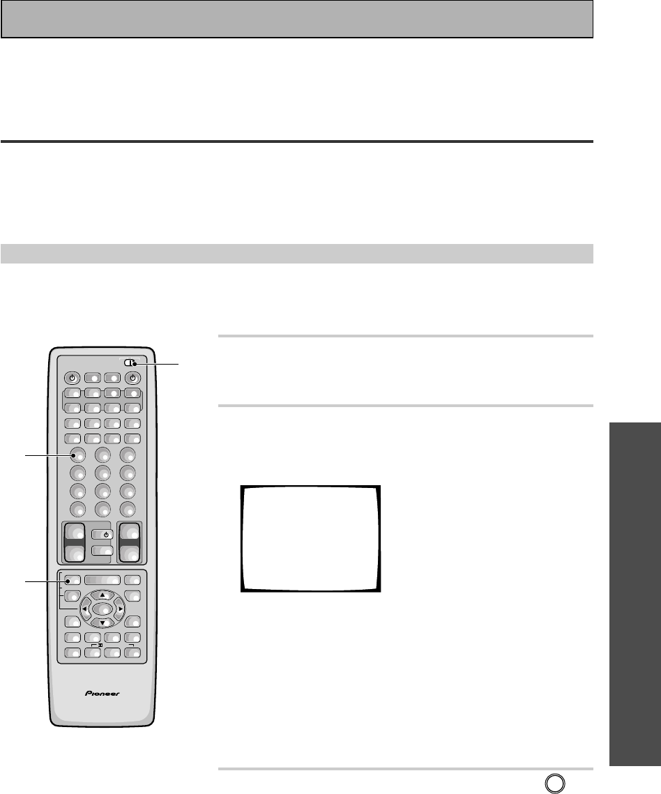
OPERATION
65
En
1 Set the remote control slide switch to
SETUP.
Also make sure that your TV is on and set to the receiver.
2 Press the REMOTE SETUP (INPUT ATT)
button.
The REMOTE SET UP menu appears on your TV screen.
Select Remote
Setup Mode
Remote SETUP+1
Preset Recall
Remote SETUP+2
Learning
Remote SETUP+3
Multi-Operation
Remote SETUP+4
Direct Function
You have four setup options:
1Preset Recall
2Learning
3Multi Operation (See p.78)
4Direct Function (See p.81)
Preset Recall and Learning are the two modes that teach the
remote control to operate your other components. It's easiest
to start with Preset Recall and, if setup isn't possible for certain
components, move on to the Learning mode.
3 Press the REMOTE SETUP button and 1 at
the same time to select the preset recall
setup mode.
All the MULTI CONTROL buttons (except the TUNER button)
start to blink.
To cancel the preset recall setup mode press REMOTE SET
UP.
Setting Up the Remote Control to Control Other
Components
In addition to controlling the receiver, the supplied remote control can operate your other components (VCR, TV,
LD, CD, etc.) after you program it to do so. In this way, instead of fumbling with many different controls and
buttons, you only need to use one remote control. If your component(s) are listed in the remote control's
memory, simply follow the steps below. If your component(s) are not listed, or if you want the remote to learn
additional operations, you can use the learning mode to input the information from the remote controls supplied
with your other components.
Recalling Preset Codes
The following steps show you how to recall preset codes stored in the remote control. Once a preset code is
recalled and the component assigned, you can use this remote to easily operate the component. See “Preset
Code List“ on page 88-91 for the components and manufacturers available.
AV PRE-PROGRAMMED AND LEARNING
REMOTE CONTROL UNIT
/DTS/MPEG
S0URCE
DVD/LD TV/SAT VCR1 VCR2
CD
TV VOL
TV FUNC
MENU
ENTER
STEREO/
DIRECT
DSP
THXLIGHT
MUTE
TV
VOLUME
MD/
TAPE1 TUNER TVCONT
RECEIVER
USE SETUP
MULTI
OPERATION
CLASS MPX
DIRECT ACCESS
CHANNEL
STATION
TUNING
DISPLAY
RF ATT
TV CONTROL
FUNCTION
REMOTE SETUP
SYSTEM SETUP
INPUT
ATT
ADVANCED
MIDNIGHT
MULTI CH
INPUT
STANDARD
DIGITAL
NR
EFFECT/
CH SEL
SIGNAL
SELECT
BAND
SYSTEM
OFF
123
456
789
0
DISC
Î
¶ 873
1¡4¢
+
-
+
-
+
-
MULTI CONTROL
++
––
+
–
+10
1
3
2,3
Remote Control of Other Components
Before operating the receiver, be sure to press the _ ON/ — OFF button on the front panel to turn the
power ON (_).
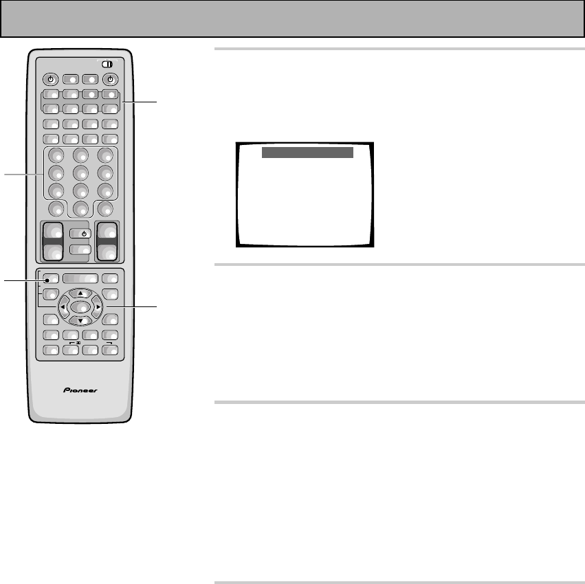
66
En
4 Press the MULTI CONTROL button for the
component you want to control.
The selected button lights steadily and the first manufacturer
(and preset code(s)) appear on your TV screen.
Preset Recall
1Select function
2Select products [5∞23]
3Input ID CODE
2 [TAPE ] 3 Page 22/22
5 [PIONEER ] ∞
[ 800 825 ]
EXIT = Remote Setup
5 Press the 2¥3 buttons to choose the
function and then press the 5¥∞ buttons
repeatedly to display the name of the
component's manufacturer.
Most manufacturers have been programmed into the receiver,
but if your component is made by a small or relatively unknown
manufacturer you may not be able to find it.
6 Point the remote toward the component to
be controlled, enter the 3 digit code.
If the component you are trying to control turns on/off, the set up
for this component is complete, but components that don't have a
standby mode can't respond in this way. To test if you've set it up
properly work through step 7. Then try using selecting the
function you just set up (for example a CD player) and using the
controls on this remote control. If the component does not
respond, try working through the procedure again and pressing
number 2 instead this time. Continue this procedure until one of
the commands works.
7 Press the REMOTE SETUP button to exit the
preset recall setup mode.
The remote control and TV return to their previous operation
modes.
• When you're done setting up, remember to set the slide
switch back to USE.
AV PRE-PROGRAMMED AND LEARNING
REMOTE CONTROL UNIT
/DTS/MPEG
S0URCE
DVD/LD TV/SAT VCR1 VCR2
CD
TV VOL
TV FUNC
MENU
ENTER
STEREO/
DIRECT
DSP
THXLIGHT
MUTE
TV
VOLUME
MD/
TAPE1 TUNER TVCONT
RECEIVER
USE SETUP
MULTI
OPERATION
CLASS MPX
DIRECT ACCESS
CHANNEL
STATION
TUNING
DISPLAY
RF ATT
TV CONTROL
FUNCTION
REMOTE SETUP
SYSTEM SETUP
INPUT
ATT
ADVANCED
MIDNIGHT
MULTI CH
INPUT
STANDARD
DIGITAL
NR
EFFECT/
CH SEL
SIGNAL
SELECT
BAND
SYSTEM
OFF
123
456
789
0
DISC
Î
¶ 873
1¡4¢
+
-
+
-
+
-
MULTI CONTROL
++
––
+
–
+10
7
5
4
6
Remote Control of Other Components
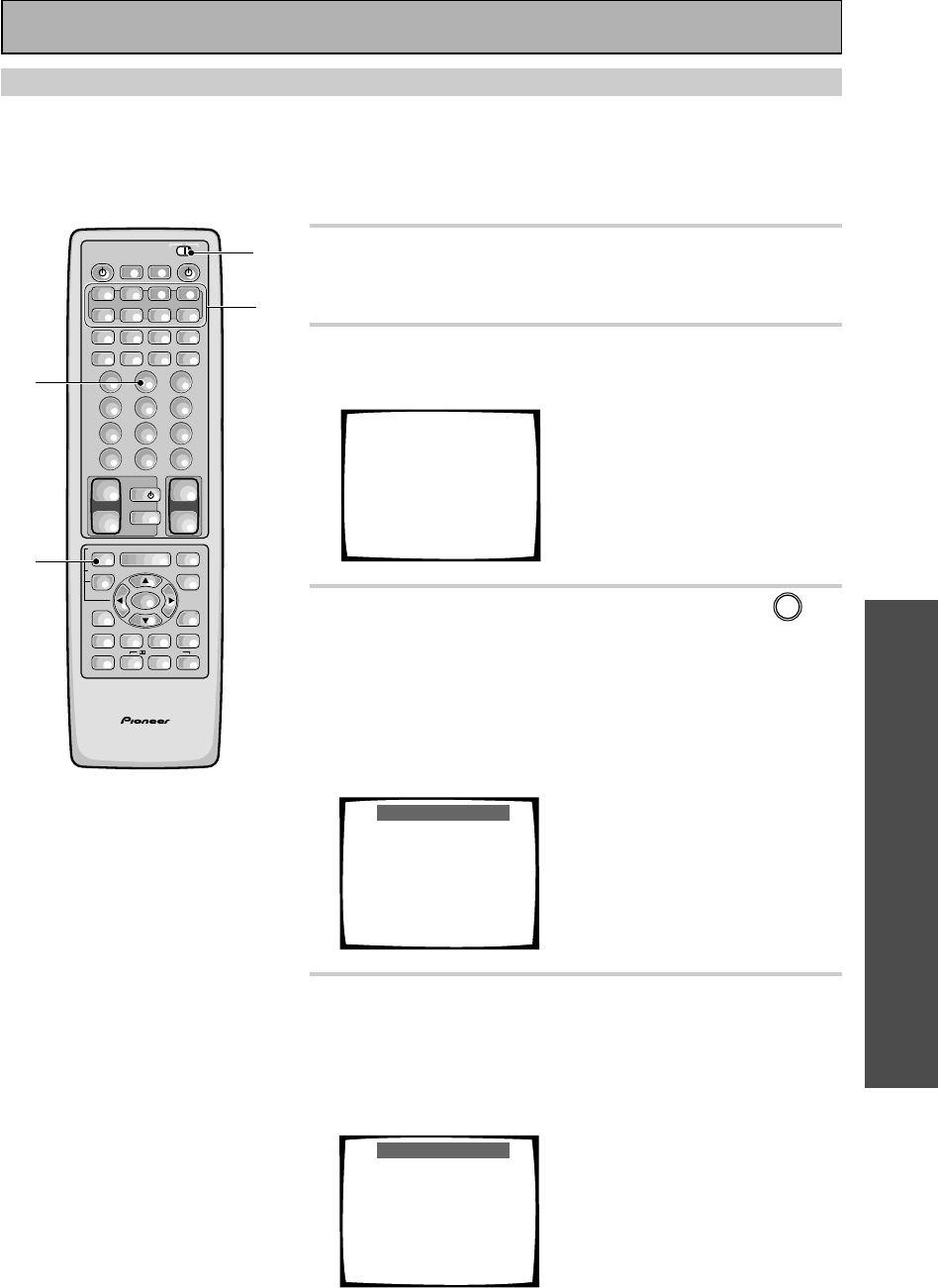
OPERATION
67
En
Learning Commands from Other Remote Controls
If preset codes are not available for your component(s), or the available preset codes do not operate correctly,
you can use this function to program in signals from the remote control(s) of your other component(s). This
operation can also be used after recalling a preset code to program additional operations not covered in the
preset codes.
1 Set the remote control slide switch to
SETUP.
Also make sure that your TV is on and set to the receiver.
2 Press the REMOTE SETUP button.
The REMOTE SET UP menu appears on your TV screen.
Select Remote
Setup Mode
Remote SETUP+1
Preset Recall
Remote SETUP+2
Learning
Remote SETUP+3
Multi-Operation
Remote SETUP+4
Direct Function
3 Press the REMOTE SETUP button and 2 at
the same time to select the Learning setup
mode.
All the MULTI CONTROL buttons (except the TUNER button)
start to blink.
To cancel Learning setup mode, press the REMOTE SET UP
button.
Learning Setup
1Place both commanders
pointing at each other.
2Select the item from
the Multi-control
buttons that should be
duplicated. (ex. DVD)
Multi-control button
starts blinking.
EXIT = Remote Setup
4 Press the MULTI CONTROL button for the
component you want to control.
Each button can be set to control one of the following compo-
nents
The selected button continues to blink.
Learning Setup
3Press one button that
should be duplicated.
4Multi-Contorol button
lights up.
5Press one button on the
original commander, and
hold 2 to 10 seconds.
6Repeat this process to
duplicate next command.
EXIT = Remote Setup
AV PRE-PROGRAMMED AND LEARNING
REMOTE CONTROL UNIT
S0URCE
DVD/LD TV/SAT VCR1 VCR2
CD
TV VOL
TV FUNC
MENU
ENTER
STEREO/
DIRECT
DSP
THXLIGHT
MUTE
TV
VOLUME
MD/
TAPE1 TUNER TVCONT
RECEIVER
USE SETUP
MULTI
OPERATION
CLASS MPX
DIRECT ACCESS
CHANNEL
STATION
TUNING
DISPLAY
RF ATT
TV CONTROL
FUNCTION
REMOTE SETUP
SYSTEM SETUP
INPUT
ATT
ADVANCED
MIDNIGHT
MULTI CH
INPUT
STANDARD
DIGITAL
NR
EFFECT/
CH SEL
SIGNAL
SELECT
BAND
SYSTEM
OFF
123
456
789
0
DISC
Î
¶ 873
1¡4¢
+
-
+
-
+
-
MULTI CONTROL
++
––
+
–
+10
1
3
2,3
4
/DTS/MPEG
Remote Control of Other Components
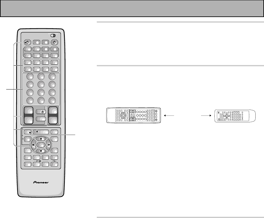
68
En
5 Press the button to be programmed.
The MULTI CONTROL button lights steadily.
• The TV POWER, TV FUNC and TV VOL +/– buttons are only
available for learning when programming TV CONTROL
operations.
6 Point the remote controls at each other and
press the button on the other remote
control for the operation you wish to
program .
5–20 cm
1Point the remote controls toward each other.
2Hold down the button on the other remote control corre-
sponding to the operation you wish to program. Release
when the MULTI CONTROL button on the receiver's remote
control starts blinking.
(The MULTI CONTROL button blinks to indicate that the
operation has been learned.)
To program additional operations for the current
component, repeat steps 5 and 6.
To program operations for another component, repeat
steps 4 through 6.
7 Press the REMOTE SETUP button to exit the
learning setup mode.
The remote control and TV return to their previous operation
modes.
• When you're done setting up, remember to set the slide
switch back to USE.
AV PRE-PROGRAMMED AND LEARNING
REMOTE CONTROL UNIT
/DTS/MPEG
S0URCE
DVD/LD TV/SAT VCR1 VCR2
CD
TV VOL
TV FUNC
MENU
ENTER
STEREO/
DIRECT
DSP
THXLIGHT
MUTE
TV
VOLUME
MD/
TAPE1 TUNER TVCONT
RECEIVER
USE SETUP
MULTI
OPERATION
CLASS MPX
DIRECT ACCESS
CHANNEL
STATION
TUNING
DISPLAY
RF ATT
TV CONTROL
FUNCTION
REMOTE SETUP
SYSTEM SETUP
INPUT
ATT
ADVANCED
MIDNIGHT
MULTI CH
INPUT
STANDARD
DIGITAL
NR
EFFECT/
CH SEL
SIGNAL
SELECT
BAND
SYSTEM
OFF
123
456
789
0
DISC
Î
¶ 873
1¡4¢
+
-
+
-
+
-
MULTI CONTROL
++
––
+
–
+10
5
7
Remote Control of Other Components
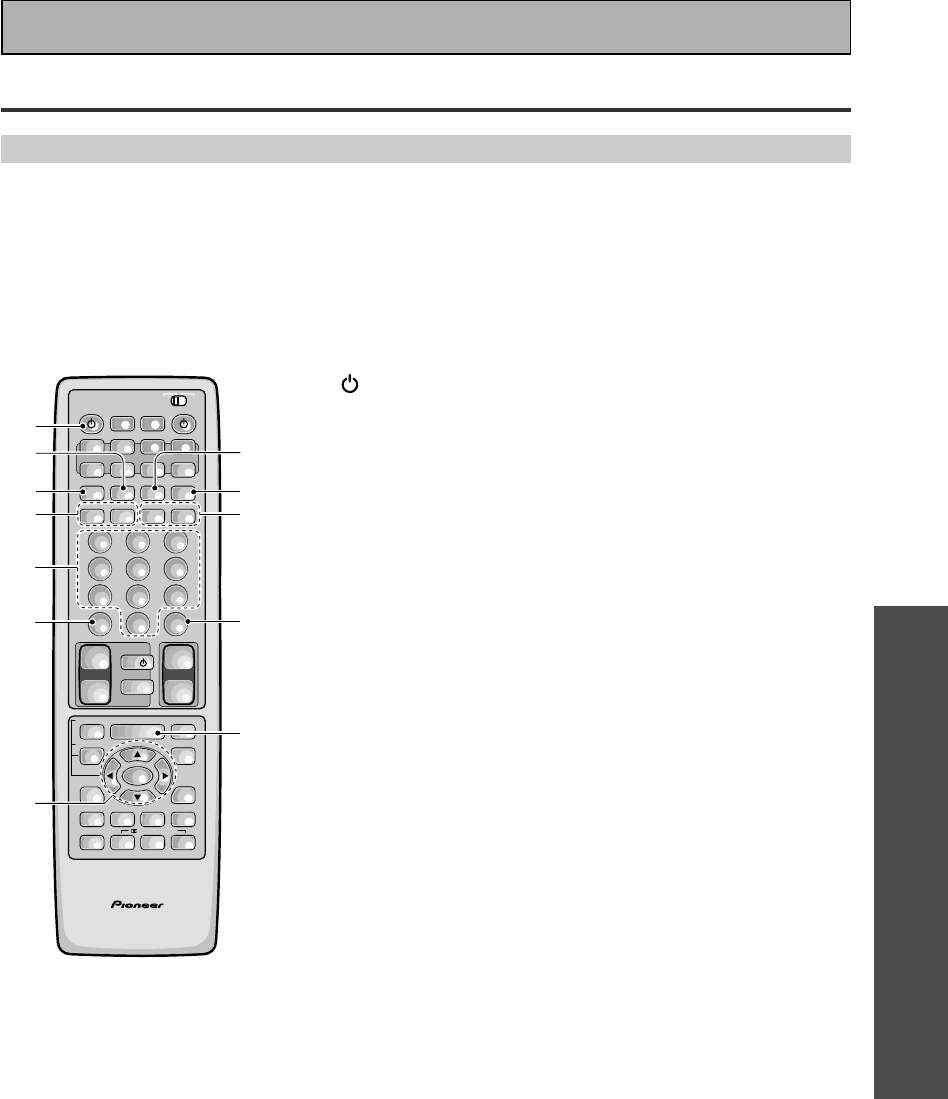
OPERATION
69
En
Using the Remote Control with Other Components
DVD or LD Player Operations
• The following operations are available from the receiver's remote control after you program your DVD
or LD player's preset code, but some operations may need to be learned by the receiver (see “Setting
Up the Remote Control to Control Other Components,“ on pages 65–68).
• To perform these operations, press the DVD/LD button to set the remote to the DVD or LD operation
mode.
• For more information on individual commands consult the manual that came with the component.
1 SOURCE
Press to switch the DVD or LD player on or off (not possible
with all models, especially those without a standby mode).
27
Press to stop playback.
3¶ (TOP MENU)
Press to call up the menu programmed on the DVD ( for DVD
only).
41˜¡
1 : Hold down for fast reverse playback.
¡ : Hold down for fast forward playback.
5Number buttons
Use to select chapters (tracks).
6+10
Use when selecting chapter (track) numbers higher than 10.
75˜∞˜2˜3˜ENTER
5˜∞˜2˜3 : Use to navigate through options on menu screens
and to change settings.
ENTER : Use to implement settings selected with the cursor
buttons or to set items highlighted in a menu (for DVD only).
83
Press to start playback.
98
Press to pause playback.
04˜¢
4 : Press to return to the beginning of the current chapter
(track). Press repeatedly to return to the beginning of previous
chapters (tracks).
¢ : Press to advance to the beginning of the next chapter
(track). Press repeatedly to advance to the beginning of follow-
ing chapters (tracks).
-DISC
Use to change the LD between sides A and B (for LD only).
=MENU
Press to bring up the disc menu.
AV PRE-PROGRAMMED AND LEARNING
REMOTE CONTROL UNIT
/DTS/MPEG
S0URCE
DVD/LD TV/SAT VCR1 VCR2
CD
TV VOL
TV FUNC
MENU
ENTER
STEREO/
DIRECT
DSP
THXLIGHT
MUTE
TV
VOLUME
MD/
TAPE1 TUNER TVCONT
RECEIVER
USE SETUP
MULTI
OPERATION
CLASS MPX
DIRECT ACCESS
CHANNEL
STATION
TUNING
DISPLAY
RF ATT
TV CONTROL
FUNCTION
REMOTE SETUP
SYSTEM SETUP
INPUT
ATT
ADVANCED
MIDNIGHT
MULTI CH
INPUT
STANDARD
DIGITAL
NR
EFFECT/
CH SEL
SIGNAL
SELECT
BAND
SYSTEM
OFF
123
456
789
0
DISC
Î
¶ 873
1¡4¢
+
-
+
-
+
-
MULTI CONTROL
++
––
+
–
+10
7
-
=
6
8
5
3
1
9
2
40
Remote Control of Other Components
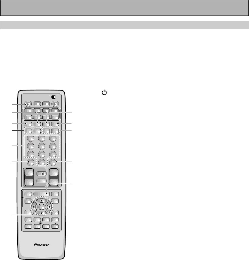
70
En
VCR & DVD Recorder Operations
• The following operations are available from the receiver's remote control after you program your VCR
or DVD video recorder's preset code, but some operations may need to be learned by the receiver
(see “Setting Up the Remote Control to Control Other Components,“ on pages 65–68).
• To perform these operations, press the VCR 1 or VCR 2 button to set the remote to the VCR, DVD
video recorder operation mode.
• For more information on individual commands consult the manual that came with the component.
1 SOURCE
Press to switch the VCR or DVD video recorder on or off (not
possible with all models, especially those without a standby
mode).
27
Press to stop playback.
3 
Press to start recording.
41˜¡
1 : Hold down for fast reverse playback.
¡ : Hold down for fast forward playback.
5Number buttons
Use to select channels.
6 +10
Use when selecting chapter (track) numbers higher than 10 (for
DVD video recorder only).
75˜∞˜2˜3˜ENTER
5˜∞˜2˜3 : Use to navigate through options on menu screens
and to change settings.
ENTER : Use to implement settings selected with the cursor
buttons or to set items highlighted in a menu (for DVD video
recorder only).
83
Press to start playback.
98
Press to pause playback.
0CHANNEL –/+
Use to change channels on the VCR's tuner.
-DISC (TV/VCR)
Use this button to switch the VCR between its tuner (for
watching videos) and the TV.
Press to stop recording (for DVD video recorder only).
=MENU
Use to display or close the title menu screen (for DVD video
recorder only).
AV PRE-PROGRAMMED AND LEARNING
REMOTE CONTROL UNIT
/DTS/MPEG
S0URCE
DVD/LD TV/SAT VCR1 VCR2
CD
TV VOL
TV FUNC
MENU
ENTER
STEREO/
DIRECT
DSP
THXLIGHT
MUTE
TV
VOLUME
MD/
TAPE1 TUNER TVCONT
RECEIVER
USE SETUP
MULTI
OPERATION
CLASS MPX
DIRECT ACCESS
CHANNEL
STATION
TUNING
DISPLAY
RF ATT
TV CONTROL
FUNCTION
REMOTE SETUP
SYSTEM SETUP
INPUT
ATT
ADVANCED
MIDNIGHT
MULTI CH
INPUT
STANDARD
DIGITAL
NR
EFFECT/
CH SEL
SIGNAL
SELECT
BAND
SYSTEM
OFF
123
456
789
0
DISC
Î
¶ 873
1¡4¢
+
-
+
-
+
-
MULTI CONTROL
++
––
+
–
+10
1
2
3
4
8
9
0
5
6
7
-
=
Remote Control of Other Components
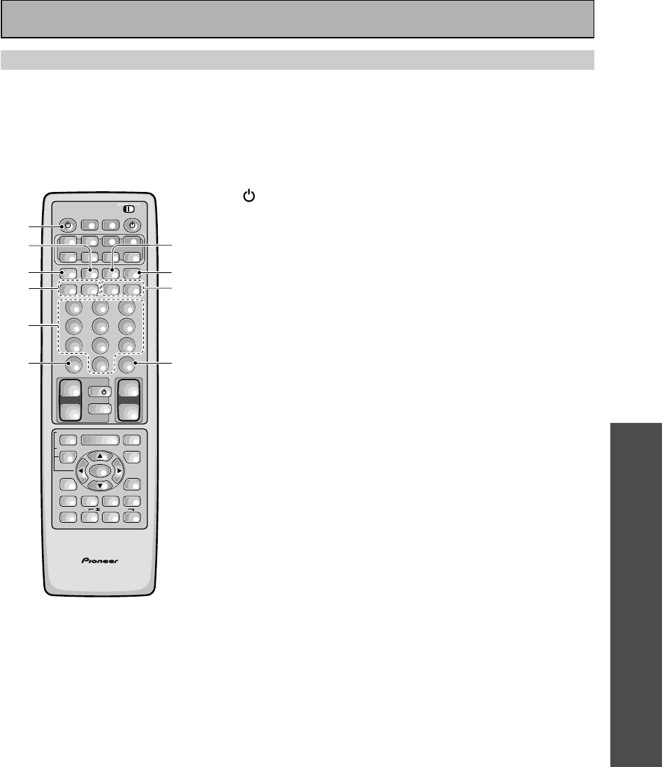
OPERATION
71
En
CD & CD-R Player Operations
• The following operations are available from the receiver's remote control after you program your CD
player or CD-R's preset code, but some operations may need to be learned by the receiver
(see
“Setting Up the Remote Control to Control Other Components,“ on pages 65–68).
• To perform these operations, press the CD button to set the remote to the CD operation mode.
• For more information on individual commands consult the manual that came with the component.
1 SOURCE
Press to switch the CD player/recorder on or off (not possible
with all models, especially those without a standby mode).
27
Press to stop playback.
3 
Press to start recording (CD-R only).
41˜¡
1 : Hold down for fast reverse playback.
¡ : Hold down for fast forward playback.
5Number buttons
Use to select channels.
6 +10
Use when selecting chapter (track) numbers higher than 10.
73
Press to start playback.
88
Press to pause playback.
94˜¢
4 : Press to return to the beginning of the current track.
Press repeatedly to return to the beginning of previous tracks.
¢ : Press to advance to the beginning of the next track. Press
repeatedly to advance to the beginning of following tracks.
0DISC
Use to switch between discs in file type disc play.
AV PRE-PROGRAMMED AND LEARNING
REMOTE CONTROL UNIT
S0URCE
DVD/LD TV/SAT VCR1 VCR2
CD
TV VOL
TV FUNC
MENU
ENTER
STEREO/
DIRECT
DSP
THXLIGHT
MUTE
TV
VOLUME
MD/
TAPE1 TUNER TVCONT
RECEIVER
USE SETUP
MULTI
OPERATION
CLASS MPX
DIRECT ACCESS
CHANNEL
STATION
TUNING
DISPLAY
RF ATT
TV CONTROL
FUNCTION
REMOTE SETUP
SYSTEM SETUP
INPUT
ATT
ADVANCED
MIDNIGHT
MULTI CH
INPUT
STANDARD
DIGITAL
NR
EFFECT/
CH SEL
SIGNAL
SELECT
BAND
SYSTEM
OFF
123
456
789
0
DISC
Î
¶ 873
1¡4¢
+
-
+
-
+
-
MULTI CONTROL
++
––
+
–
+10
1
2
3
4
7
8
9
5
60
/DTS/MPEG
Remote Control of Other Components
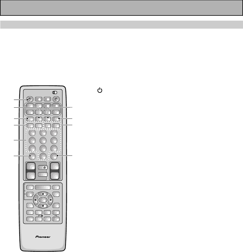
72
En
MD Operations
• The following operations are available from the receiver's remote control after you program your MD
recorder's preset code, but some operations may need to be learned by the receiver (see “Setting up
the Remote Control to Control Other Components,“ on pages 65–68).
• To perform these operations, press the MD/TAPE 1 button to set the remote to the MD operation
mode.
• For more information on individual commands consult the manual that came with the component.
1 SOURCE
Press to switch the MD player on or off (not possible with all
models, especially those without a standby mode).
27
Press to stop playback or recording.
3
Press to start recording (may put some decks in REC PAUSE
mode).
41˜¡
1 : Hold down for fast reverse playback.
¡ : Hold down for fast forward playback.
5Number buttons
Use to select tracks.
6+10
You can also use this button when selecting track numbers
higher than 10. It's especially used for track numbers 11-19.
73
Press to start playback.
88
Press to pause playback.
94˜¢
4 : Press to return to the beginning of the current track.
Press repeatedly to return to the beginning of previous tracks.
¢ : Press to advance to the beginning of the next track. Press
repeatedly to advance to the beginning of following tracks.
0DISC (DISPLAY)
Allows you to change the display mode of the MD.
AV PRE-PROGRAMMED AND LEARNING
REMOTE CONTROL UNIT
S0URCE
DVD/LD TV/SAT VCR1 VCR2
CD
TV VOL
TV FUNC
MENU
ENTER
STEREO/
DIRECT
DSP
THXLIGHT
MUTE
TV
VOLUME
MD/
TAPE1 TUNER TVCONT
RECEIVER
USE SETUP
MULTI
OPERATION
CLASS MPX
DIRECT ACCESS
CHANNEL
STATION
TUNING
DISPLAY
RF ATT
TV CONTROL
FUNCTION
REMOTE SETUP
SYSTEM SETUP
INPUT
ATT
ADVANCED
MIDNIGHT
MULTI CH
INPUT
STANDARD
DIGITAL
NR
EFFECT/
CH SEL
SIGNAL
SELECT
BAND
SYSTEM
OFF
123
456
789
0
DISC
Î
¶ 873
1¡4¢
+
-
+
-
+
-
MULTI CONTROL
++
––
+
–
+10
1
2
3
4
7
8
9
5
60
/DTS/MPEG
Remote Control of Other Components

OPERATION
73
En
1 SOURCE
Press to switch the satellite tuner on or off (not possible with
all models, especially those without a standby mode).
2¶˜7˜3˜8˜1 (A/B/C/D/E)
Use to make selections from Satellite functions.
3Number buttons
Use to select satellite channels.
4GUIDE
Use to turn the program information screen on or off.
55˜∞˜2˜3˜ENTER
5˜∞˜2˜3 : Press the button to select items on the
SAT GUIDE screen or SAT MENU screen.
ENTER : Press to activate the selected function.
6EXIT
Press to exit the current setting of the SAT.
7MENU
Use to turn the main menu on or off.
STB (satellite tuner) Operations
• The following operations are available from the receiver's remote control after you program your
satellite tuner's (or cable TV's) preset code, but some operations may need to be learned by the
receiver
(see “Setting Up the Remote Control to Control Other Components,“ on pages 65–68).
• To perform these operations, press the TV/SAT button to set the remote to the SAT operation mode.
• For more information on individual commands consult the manual that came with the component.
AV PRE-PROGRAMMED AND LEARNING
REMOTE CONTROL UNIT
S0URCE
DVD/LD TV/SAT VCR1 VCR2
CD
TV VOL
TV FUNC
MENU
ENTER
STEREO/
DIRECT
DSP
THXLIGHT
MUTE
TV
VOLUME
MD/
TAPE1 TUNER TVCONT
RECEIVER
USE SETUP
MULTI
OPERATION
CLASS MPX
DIRECT ACCESS
CHANNEL
STATION
TUNING
DISPLAY
RF ATT
TV CONTROL
FUNCTION
REMOTE SETUP
SYSTEM SETUP
INPUT
ATT
ADVANCED
MIDNIGHT
MULTI CH
INPUT
STANDARD
DIGITAL
NR
EFFECT/
CH SEL
SIGNAL
SELECT
BAND
SYSTEM
OFF
123
456
789
0
DISC
Î
¶ 873
1¡4¢
+
-
+
-
+
-
MULTI CONTROL
++
––
+
–
+10
1
2
3
4
5
6
7
/DTS/MPEG
Remote Control of Other Components
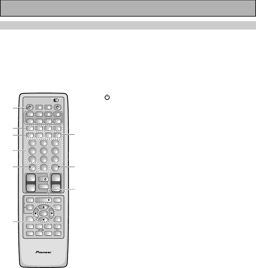
74
En
TV Operations
• The following operations are available from the receiver's remote control after you program your TV's
preset code, but some operations may need to be learned by the receiver (see “Setting Up the
Remote Control to Control Other Components,“ on pages 65–68).
• To perform these operations, press the TV/SAT or TV CONT button to set the remote to the TV
operation mode.
• For more information on individual commands consult the manual that came with the your TV.
1 SOURCE
Press to switch the TV on or off (not possible with all models,
especially those without a standby mode).
2Number buttons
Use to select a specific TV channel.
3+10
Use to select a specific TV channel.
45˜∞˜2˜3˜ENTER
5˜∞˜2˜3˜ : Press to select or adjust items on the
menu screen.
ENTER : Press to activate the selected function.
5CHANNEL –/+
Use to select a TV channel.
6DISC (CH ENTER)
Use to select the channel specified with the number buttons
(not all models require this step).
7MENU
Press to select the TV menu.
For Digital TVs:
8¶˜7˜3˜8˜1 (BLUE/GREEN/RED/
YELLOW)
Use to make selections from the DTV menu.
91˜¡
1 : Press to DTV mode on or off.
¡ : Press to select the DTV menu.
AV PRE-PROGRAMMED AND LEARNING
REMOTE CONTROL UNIT
S0URCE
DVD/LD TV/SAT VCR1 VCR2
CD
TV VOL
TV FUNC
MENU
ENTER
STEREO/
DIRECT
DSP
THXLIGHT
MUTE
TV
VOLUME
MD/
TAPE1 TUNER TVCONT
RECEIVER
USE SETUP
MULTI
OPERATION
CLASS MPX
DIRECT ACCESS
CHANNEL
STATION
TUNING
DISPLAY
RF ATT
TV CONTROL
FUNCTION
REMOTE SETUP
SYSTEM SETUP
INPUT
ATT
ADVANCED
MIDNIGHT
MULTI CH
INPUT
STANDARD
DIGITAL
NR
EFFECT/
CH SEL
SIGNAL
SELECT
BAND
SYSTEM
OFF
123
456
789
0
DISC
Î
¶ 873
1¡4¢
+
-
+
-
+
-
MULTI CONTROL
++
––
+
–
+10
1
7
5
2
3
4
6
/DTS/MPEG
-
9
8
Remote Control of Other Components
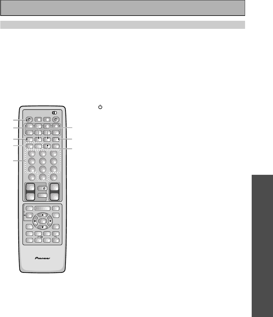
OPERATION
75
En
1 SOURCE
Press to switch the cassette deck on or off (not possible with
all models, especially those without a standby mode).
27
Press to stop playback or recording.
3
Press to start recording.
41˜¡
1 : Press to rewind the tape.
¡ : Press to fast forward the tape.
5Number buttons (1-6)
1 : 7 (Press to stop playback or recording.)
2 : 3 (Press to start playback of the side of the cassette which
has been loaded as the front.)
3 : 8 (Press to pause playback or recording.)
4 : 1 (Press to rewind the tape.)
5 : 2 (Press to start reverse playback.)
6 : ¡ (Press to fast forward the tape.)
63
Press to start playback of the side of the cassette which has
been loaded as the front.
78
Press to pause playback or recording.
84
Press to start reverse playback (for auto reverse decks).
Cassette Deck Operations
You can use this remote control to control most cassette decks, though with some models the functions
may differ.
• The following operations are available from the receiver's remote control after you recall a cassette
deck's preset code
,
but some operations may need to be learned by the receiver (see “Setting Up the
Remote Control to Control Other Components,“ on pages 65–68).
• To perform these operations, press the MD/TAPE 1 button to set the remote to the TAPE operation
mode.
• For more information on individual commands consult the manual that came with the component.
AV PRE-PROGRAMMED AND LEARNING
REMOTE CONTROL UNIT
S0URCE
DVD/LD TV/SAT VCR1 VCR2
CD
TV VOL
TV FUNC
MENU
ENTER
STEREO/
DIRECT
DSP
THXLIGHT
MUTE
TV
VOLUME
MD/
TAPE1 TUNER TVCONT
RECEIVER
USE SETUP
MULTI
OPERATION
CLASS MPX
DIRECT ACCESS
CHANNEL
STATION
TUNING
DISPLAY
RF ATT
TV CONTROL
FUNCTION
REMOTE SETUP
SYSTEM SETUP
INPUT
ATT
ADVANCED
MIDNIGHT
MULTI CH
INPUT
STANDARD
DIGITAL
NR
EFFECT/
CH SEL
SIGNAL
SELECT
BAND
SYSTEM
OFF
123
456
789
0
DISC
Î
¶ 873
1¡4¢
+
-
+
-
+
-
MULTI CONTROL
++
––
+
–
+10
1
2
3
4
6
7
8
5
/DTS/MPEG
Remote Control of Other Components
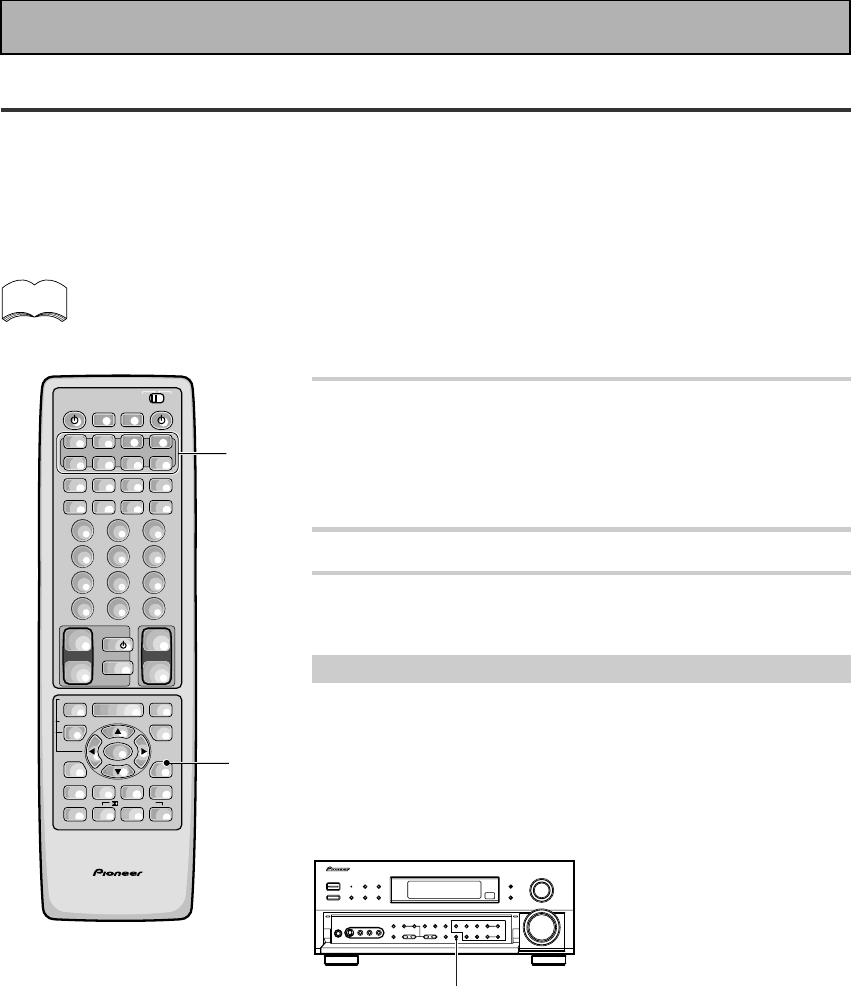
76
En
Recording from Audio Components
The following explanations show you how to record an analog or digital audio signal. Note that your analog
components cannot record a player that is only connected digitally (and vice-versa). If you want to record from a
digital component to an analog one (for example, a tape deck), or vice-versa, the digital component it must be
connected via analog jacks and you need to set the SIGNAL SELECT switch to ANALOG. To make exact digital
copies (of digital sources like CDs) both the source component and the recorder must be connected with digital
connections. See p.12 for more on analog audio connections and p.13 for digital audio connections.
The receiver's volume, channel level, TONE, DIGITAL NR, MIDNIGHT, LOUDNESS and surround effects
have no effect on the recorded signal and the MULTI CH IN cannot be recorded.
In some cases, digital recordings have copy guard protections and making a digital copy is not possible.
In this case you can only copy them in an analog manner.
1 Select the source component. Set SIGNAL
SELECT according to the source
component's signal (ANALOG or DIGITAL).
Press the SIGNAL SELECT button on the remote control (or
use the button on the front panel) and choose ANALOG.
2 Start recording with a recorder.
3 Playback the source to be recorded.
Record monitor (TAPE 2 MONITOR)
If you connect a cassette deck with a record monitor function to the
TAPE 2 MONITOR jacks, you can listen to the sound of an analog
recording as it is being recorded.
Press TAPE 2 MONITOR to switch between the sound of the
recording (TAPE 2 indicator on) and the sound of the source
component (TAPE 2 indicator off).
memo
AV PRE-PROGRAMMED AND LEARNING
REMOTE CONTROL UNIT
S0URCE
DVD/LD TV/SAT VCR1 VCR2
CD
TV VOL
TV FUNC
MENU
ENTER
STEREO/
DIRECT
DSP
THXLIGHT
MUTE
TV
VOLUME
MD/
TAPE1 TUNER TVCONT
RECEIVER
USE SETUP
MULTI
OPERATION
CLASS MPX
DIRECT ACCESS
CHANNEL
STATION
TUNING
DISPLAY
RF ATT
TV CONTROL
FUNCTION
REMOTE SETUP
SYSTEM SETUP
INPUT
ATT
ADVANCED
MIDNIGHT
MULTI CH
INPUT
STANDARD
DIGITAL
NR
EFFECT/
CH SEL
SIGNAL
SELECT
BAND
SYSTEM
OFF
123
456
789
0
DISC
Î
¶ 873
1¡4¢
+
-
+
-
+
-
MULTI CONTROL
++
––
+
–
+10
1
1
/DTS/MPEG
TAPE 2 MONITOR
Using Other Functions
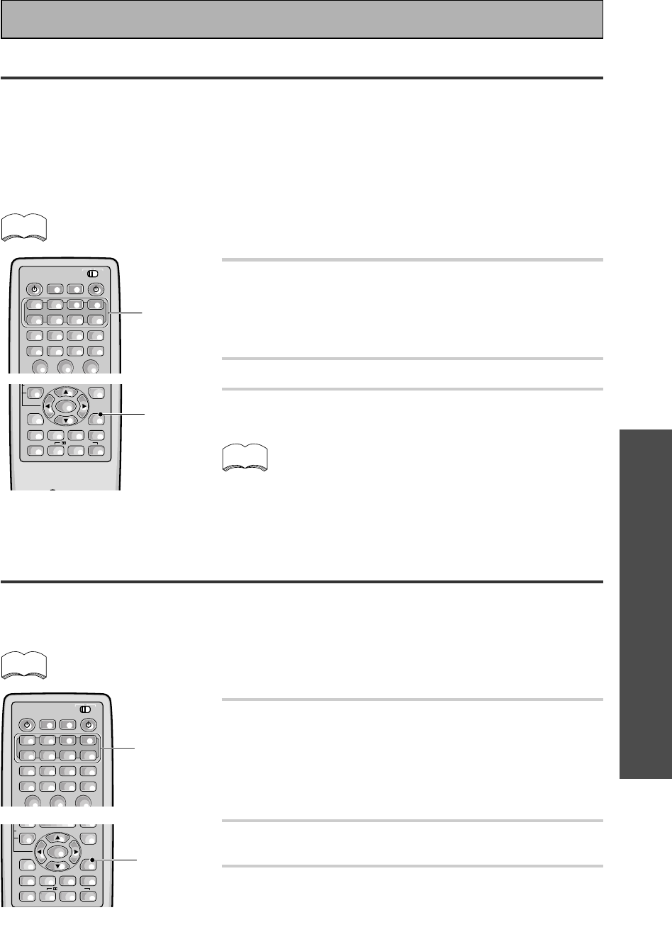
OPERATION
77
En
Recording from Video Components
The following operations show you how to record audio and video to the video tape recorder connected to the
VCR 1/DVR or VCR 2 jacks. Note that all signals coming out of these jacks will be analog and it is not possible to
record Dolby Digital/DTS soundtracks.
The receiver's volume, channel level, balance, TONE, DIGITAL NR, MIDNIGHT, LOUDNESS and sur-
round effects have no effect on the recorded signal.
1 First, decide the component you'd like to
record and put the receiver in that function.
Set the SIGNAL SELECT to ANALOG.
Press the SIGNAL SELECT button on the remote control (or
use the button on the front panel) and choose analog. Record-
ing DIGITAL or 2 RF signals is not possible.
2 Start recording with VCR 1 or VCR 2 (etc.).
3 Playback the source to be recorded.
memo
Recording from Digital Audio Components
The following explanations show you how to record digital audio. Using this method you can make exact digital
copies of sources like CDs or MDs. The only drawback is that you cannot switch between various recorders at
the touch of a button like you can with analog recordings (see the previous page). If you look on the back of the
receiver you will find 2 digital out jacks which are marked PCM/2/DTS/MPEG OUT (these are to the right of the
digital in jacks in the upper left-hand corner). If you connect one of these to the optical input on a digital recorder
(currently these include MD, DAT, and CD-R), you can make direct digital recordings with this unit. Of course,
the digital components you want to record, all need to be connected to the receiver with digital inputs as well.
See p.13 if you have not made these connections.
The receiver’s volume, channel level, tone (BASS, TREBLE, and LOUDNESS), and surround
effects have no effect on the recorded signal.
1 Prepare the source you want to record and
put the receiver in that function. Set
SIGNAL SELECT to DIGITAL.
Press the SIGNAL SELECT button on the remote control (or use
the button on the front panel) and choose DIGITAL.
2 Start recording with a CD-R or MD (etc.).
3 Play back the source to be recorded.
In some cases, digital recordings have copy guard protections
on them and making a digital copy is not possible. It is still
possible to copy these digital sources if you have hooked the
components up with analog connections (in this case, the cop-
ies will not be exact digital reproductions). Refer to the previ-
ous page in this case.
memo
memo
Using Other Functions
S0URCE
DVD/LD TV/SAT VCR1 VCR2
CD MD/
TAPE1 TUNER TVCONT
RECEIVER
USE SETUP
MULTI
OPERATION
CLASS MPX
DIRECT ACCESS
CHANNEL
STATION
TUNING
BAND
SYSTEM
OFF
123
Î
¶ 873
1¡4¢
+
-
+
-
+
-
MULTI CONTROL
1
ENTER
STEREO/
DIRECT
DSP
THXLIGHT
FUNCTION
SYSTEM
SETUP
ADVANCED
MIDNIGHT
MULTI CH
INPUT
STANDARD
DIGITAL
NR
EFFECT/
CH SEL
SIGNAL
SELECT
+
–
1
/DTS/MPEG
S0URCE
DVD/LD TV/SAT VCR1 VCR2
CD MD/
TAPE1 TUNER TVCONT
RECEIVER
USE SETUP
MULTI
OPERATION
CLASS MPX
DIRECT ACCESS
CHANNEL
STATION
TUNING
BAND
SYSTEM
OFF
123
Î
¶ 873
1¡4¢
+
-
+
-
+
-
MULTI CONTROL
1
ENTER
STEREO/
DIRECT
DSP
THXLIGHT
FUNCTION
SYSTEM SETUP
ATT
ADVANCED
MIDNIGHT
MULTI CH
INPUT
STANDARD
DIGITAL
NR
EFFECT/
CH SEL
SIGNAL
SELECT
+
–
1
/DTS/MPEG
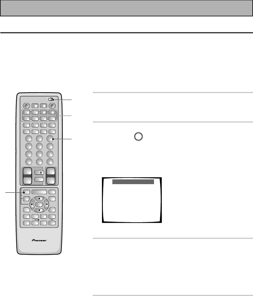
78
En
Multi Operations
A Multi Operation is a sequence of commands programmed into a single button to save you a lot of repetitive
button pressing. Once setup, pressing the MULTI OPERATION button followed by one of the MULTI CONTROL
buttons will switch on that component, the receiver and your TV, and switch the function of the receiver to that
component. Up to five more commands can be programmed into a Multi Operation, such as changing the sound
mode of the receiver and starting playback of the source.
Important: For Multi Operations to work with other non-Pioneer components, you must first setup the remote to
control those other components—see pages 65-68 for more on this.
1 Set the remote control slide switch to
SETUP.
Also make sure that your TV is on and set to the receiver.
2 Press the REMOTE SETUP button (INPUT
ATT) and
3
at the same time to select the
MULTI OPERATION SETUP mode.
The REMOTE SETUP menu appears on your TV screen. The
MULTI CONTROL and the SYSTEM OFF buttons start to blink
(see the following page for more on the SYSTEM OFF button).
Multi-operation
1Select an item from the
Multi-Contorol buttons.
(ex. DVD)
2Select the operation
button. (ex. DVD = MENU)
3First command has been
learned.
4You can repeat this
proccess for 5 commands.
EXIT = Remote Setup
• To cancel here, press REMOTE SETUP.
3 Select a MULTI CONTROL button for this
MULTI OPERATION.
Each MULTI CONTROL button can be used for one Multi
Operation. If a Multi Operation relates to using a DVD player,
for example, it makes sense to select the DVD/LD button.
After pressing a MULTI CONTROL button, just that button will
remain blinking.
4 Select the MULTI CONTROL button for a
source component.
For example, if you want this Multi Operation to switch on your
DVD player press the DVD/LD.
After pressing a MULTI CONTROL button, that button stays lit.
AV PRE-PROGRAMMED AND LEARNING
REMOTE CONTROL UNIT
S0URCE
DVD/LD TV/SAT VCR1 VCR2
CD
TV VOL
TV FUNC
MENU
ENTER
STEREO/
DIRECT
DSP
THXLIGHT
MUTE
TV
VOLUME
MD/
TAPE1 TUNER TVCONT
RECEIVER
USE SETUP
MULTI
OPERATION
CLASS MPX
DIRECT ACCESS
CHANNEL
STATION
TUNING
DISPLAY
RF ATT
TV CONTROL
FUNCTION
REMOTE SETUP
SYSTEM SETUP
INPUT
ATT
ADVANCED
MIDNIGHT
MULTI CH
INPUT
STANDARD
DIGITAL
NR
EFFECT/
CH SEL
SIGNAL
SELECT
BAND
SYSTEM
OFF
123
456
789
0
DISC
Î
¶ 873
1¡4¢
+
-
+
-
+
-
MULTI CONTROL
++
––
+
–
+10
1
2
2
3,4
/DTS/MPEG
Using Other Functions
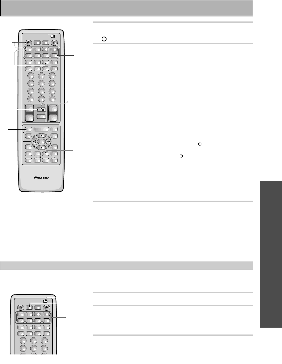
OPERATION
79
En
Performing Multi Operations
Once you've programmed a Multi Operation, here's how to use it.
1 Set the remote control slide switch to USE.
2 Press the MULTI OPERATION button on the
remote control.
The MULTI CONTROL buttons start to blink.
3 Press the MULTI CONTROL button to
activate that Multi Operation.
The remote sends the Multi Operation commands you pro-
grammed.
5 Press the operation button, for example TV
(POWER), you want to input.
6 Repeat steps 4 and 5 to input MULTI
OPERATIONs to the MULTI CONTROL
button you pressed in step 3. You can also
tell the receiver to go into a specific sound
mode (THX, ADVANCED, STANDARD,
MULTI CH IN, MIDNIGHT, DSP, DNR or
STEREO) by inputting that command (for
example, see operation 4 below).
You can repeat this process for up to five commands.
For example : you could enter the following four operations using
the preceeding steps 4 and 5.
1Press the TV CONTROL button and TV (POWER) to turn on
your TV (as explained above).
2Press the DVD/LD button then (POWER) to turn on your
DVD player (if it is not a PIONEER product).
3Press the DVD/LD button then 3 (play) to start playing the
DVD player.
4Press the ADVANCED button to put the receiver in that sound
mode.
When you employ MULTI OPERATIONs (see below), these four
tasks will be performed in the same order.
7 Press the REMOTE SETUP button to exit the
Multi-operation setup mode.
The remote control and TV return to their previous operation
modes.
AV PRE-PROGRAMMED AND LEARNING
REMOTE CONTROL UNIT
S0URCE
DVD/LD TV/SAT VCR1 VCR2
CD
TV VOL
TV FUNC
MENU
ENTER
STEREO/
DIRECT
DSP
THXLIGHT
MUTE
TV
VOLUME
MD/
TAPE1 TUNER TVCONT
RECEIVER
USE SETUP
MULTI
OPERATION
CLASS MPX
DIRECT ACCESS
CHANNEL
STATION
TUNING
DISPLAY
RF ATT
TV CONTROL
FUNCTION
REMOTE SETUP
SYSTEM SETUP
INPUT
ATT
ADVANCED
MIDNIGHT
MULTI CH
INPUT
STANDARD
DIGITAL
NR
EFFECT/
CH SEL
SIGNAL
SELECT
BAND
SYSTEM
OFF
123
456
789
0
DISC
Î
¶ 873
1¡4¢
+
-
+
-
+
-
MULTI CONTROL
++
––
+
–
+10
7
5
6-
2
6-
3
6-
1
6-
4
/DTS/MPEG
Using Other Functions
RECEIVERS0URCE
DVD/LD TV/SAT VCR1 VCR2
CD MD/
TAPE1 TUNER TVCONT
USE SETUP
MULTI
OPERATION
CLASS MPX
DIRECT ACCESS
CHANNEL
STATION
TUNING
BAND
SYSTEM
OFF
123
456
789
Î
¶ 873
1¡4¢
+
-
+
-
+
-
MULTI CONTROL
2
3
1
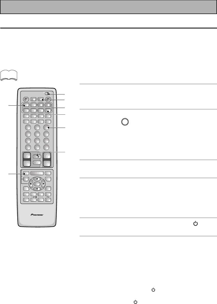
80
En
System Off
The SYSTEM OFF feature allows you to tell the receiver and your other components to stop and turn off with
the push of only one button on the remote control (this feature will only work with components that have a
standby mode). For example, you can program the unit to stop your DVD, turn off your TV, turn off your DVD
player and turn off the receiver itself. You don't need to program in other the power for PIONEER components,
they will go off automatically in this mode. The receiver itself will go off automatically as well.
The steps below show you how to program a string of up to 5 different SYSTEM OFF operations based on eight
possible components.
Be sure to recall or teach the remote control commands for each component before attempting
MULTI OPERATIONS (see “Setting Up the Remote Control to Control Other Components,“ page 65-
68).
1 Set the remote control slide switch to
SETUP.
Also make sure that your TV is on and set to the receiver.
2 Press the REMOTE SETUP (INPUT ATT)
button and
3
at the same time to select
the MULTI OPERATION SETUP mode.
The REMOTE SETUP menu appears on your TV screen. The
MULTI CONTROL and the SYSTEM OFF buttons start to blink.
To cancel MULTI OPERATION SETUP mode, press REMOTE
SETUP.
3 Press the SYSTEM OFF button.
The SYSTEM OFF button will blink.
4 Press the MULTI CONTROL button for the
component whose operation you want to
start SYSTEM OFF with (for example, TV
CONT button).
The selected button will light steadily.
5 Press the operation, for example TV
(POWER), you want to input.
6 Repeat steps 3 and 4 to program a sequence
of up to five stop or power off commands
you want to input.
You can repeat this process for up to five
commands.
For example : you could enter the following two operations
using the proceeding steps 3 and 4.
1Press TV CONT button & TV (POWER) to turn off your TV
(as explained above).
2Press DVD/LD then (POWER) to turn off your DVD player
(if it is not a PIONEER product).
When you employ SYSTEM OFF (see below), these two tasks
will be performed in the same order.
• To exit STSTEM OFF SETUP mode, press REMOTE SETUP.
• When you're done setting up, remember to set the slide
switch back to USE.
memo
AV PRE-PROGRAMMED AND LEARNING
REMOTE CONTROL UNIT
S0URCE
DVD/LD TV/SAT VCR1 VCR2
CD
TV VOL
TV FUNC
MENU
ENTER
STEREO/
DIRECT
DSP
THXLIGHT
MUTE
TV
VOLUME
MD/
TAPE1 TUNER TVCONT
RECEIVER
USE SETUP
MULTI
OPERATION
CLASS MPX
DIRECT ACCESS
CHANNEL
STATION
TUNING
DISPLAY
RF ATT
TV CONTROL
FUNCTION
REMOTE SETUP
SYSTEM SETUP
INPUT
ATT
ADVANCED
MIDNIGHT
MULTI CH
INPUT
STANDARD
DIGITAL
NR
EFFECT/
CH SEL
SIGNAL
SELECT
BAND
SYSTEM
OFF
123
456
789
0
DISC
Î
¶ 873
1¡4¢
+
-
+
-
+
-
MULTI CONTROL
++
––
+
–
+10
1
3
4
6-
1
2
6-
2
2
5
/DTS/MPEG
Using Other Functions
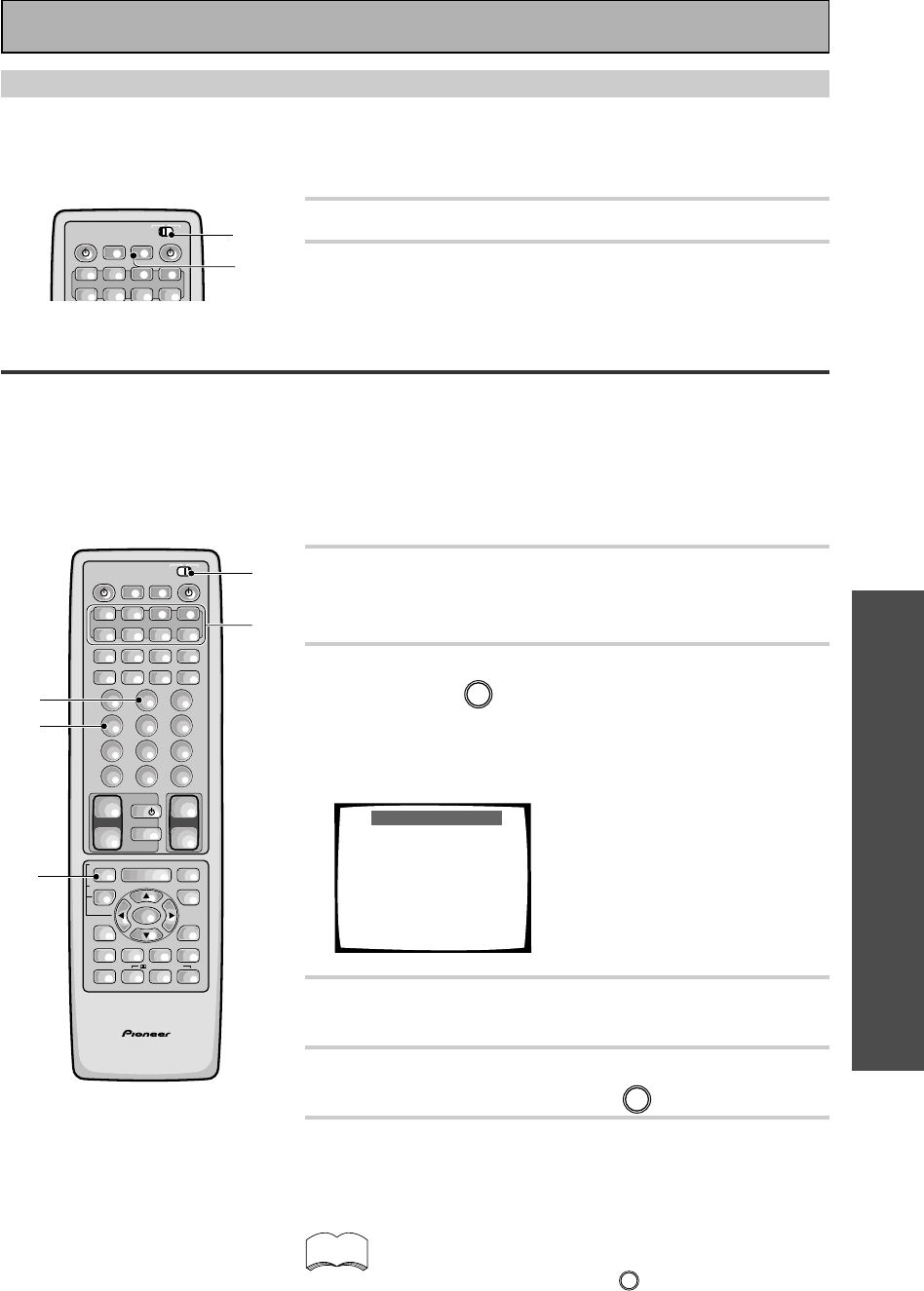
OPERATION
81
En
Setting Up the Direct Function
The DIRECT FUNCTION is designed in case you have an external video source connected to your TV (a video
source that is not going through the receiver). For this explanation we'll call this the "external video deck." You'd
like to control the external video deck with this unit's remote control so you've assigned it a function button (for
example purposes, the VCR 2 button). Yet, if you put the receiver in VCR 2 mode you'll get no picture on your
TV because the external video deck signal is not going through the receiver. To get around this problem you set
the DIRECT FUNCTION for VCR 2 to OFF. Now when you press VCR 2 function button you can control the
external video deck with the remote but the receiver does not go into VCR 2 mode.
1 Set the remote control slide switch to
SETUP.
Also make sure that your TV is on and set to the receiver.
2 Press the REMOTE SETUP (INPUT ATT)
button and 4 at the same time to select
the DIRECT FUNCTION mode.
The MULTI CONTROL buttons DVD/LD, TV/SAT, VCR 1, VCR 2,
CD, and MD/TAPE 1 start to blink.
Direct Function
You can choose whether
the commander sends a
function code or not ,
when you press each
Multi-control button.
1Select function.
2Input YES or NO.
TRANSMIT YES =1
NO =2
EXIT = Remote Setup
3 Select a component by pressing its MULTI
CONTROL button.
4 Set the DIRECT FUNCTION of each external
source to NO by pressing 2.
5 Press the REMOTE SETUP button to exit the
DIRECT FUNCTION mode.
• When you're done setting up, remember to set the slide
switch back to USE.
The default setting is all YES. If you have turned a DIRECT
FUNCTION to NO and want to turn it back to YES, follow
the directions above and press
1
in step 3.
memo
Using the System Off Button
This button will turn off the receiver and any component that has programmed into the SYSTEM OFF settings
(see above) as well as turn off all PIONEER components regardless of whether they have been programmed
into SYSTEM OFF. If you use this feature when a DVD is playing, the player will stop the play mode before
switching off.
1 Set the remote control slide switch to USE.
2 Press the SYSTEM OFF button on the
remote control.
RECEIVERS0URCE
DVD/LD TV/SAT VCR1 VCR2
CD MD/
TAPE1 TUNER TVCONT
USE SETUP
MULTI
OPERATION
SYSTEM
OFF
Î
MULTI CONTROL
2
1
AV PRE-PROGRAMMED AND LEARNING
REMOTE CONTROL UNIT
S0URCE
DVD/LD TV/SAT VCR1 VCR2
CD
TV VOL
TV FUNC
MENU
ENTER
STEREO/
DIRECT
DSP
THXLIGHT
MUTE
TV
VOLUME
MD/
TAPE1 TUNER TVCONT
RECEIVER
USE SETUP
MULTI
OPERATION
CLASS MPX
DIRECT ACCESS
CHANNEL
STATION
TUNING
DISPLAY
RF ATT
TV CONTROL
FUNCTION
REMOTE SETUP
SYSTEM SETUP
INPUT
ATT
ADVANCED
MIDNIGHT
MULTI CH
INPUT
STANDARD
DIGITAL
NR
EFFECT/
CH SEL
SIGNAL
SELECT
BAND
SYSTEM
OFF
123
456
789
0
DISC
Î
¶ 873
1¡4¢
+
-
+
-
+
-
MULTI CONTROL
++
––
+
–
+10
1
2,5
2
4
3
/DTS/MPEG
Using Other Functions
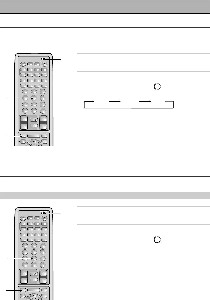
82
En
Remote Back Light
When you press any button on the remote all the buttons light for a few seconds. You can change the strength
of this light here. The default backlighting mode is Mid, Max is the strongest. Mid is slightly weaker. There's
also the option to switch off backlighting altogether. This extends battery life considerably.
1 Set the remote control slide switch to
SETUP.
2 Press and hold both the REMOTE SETUP
(INPUT ATT) button and 5.
The remote back light options cycle in the following order:
MID MAX OFF
The default setting is MID.
• When you're done setting up, remember to set the slide
switch back to USE.
Resetting the Remote Control
The following operations allow you to erase the settings stored in the remote control.
Erasing Multi Operations
1 Set the remote control slide switch to
SETUP.
2 Press and hold both the REMOTE SETUP
(INPUT ATT) button and 8 for more than 3
seconds.
The MULTI CONTROL buttons will blink 3 times and all multi
operation settings will be erased.
• When you're done setting up, remember to set the slide
switch back to USE.
S0URCE
DVD/LD TV/SAT VCR1 VCR2
CD
TV VOL
TV FUNC
MENU MUTE
TV
VOLUME
MD/
TAPE1 TUNER TVCONT
RECEIVER
USE SETUP
MULTI
OPERATION
CLASS MPX
DIRECT ACCESS
CHANNEL
STATION
TUNING
DISPLAY
RF ATT
TV CONTROL
FUNCTION
REMOTE SETUP
SYSTEM SETUP
INPUT
ATT
EFFECT/
CH SEL
BAND
SYSTEM
OFF
123
456
789
0
DISC
Î
¶ 873
1¡4¢
+
-
+
-
+
-
MULTI CONTROL
++
––
+
+10
1
2
2
Using Other Functions
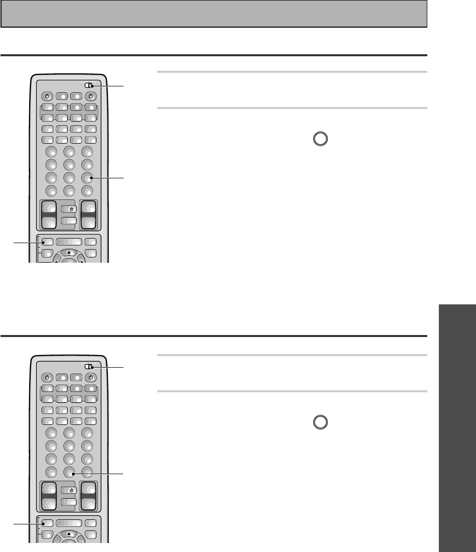
OPERATION
83
En
Erasing Learned Remote Control Commands
Erasing All Learned Commands and Preset Codes
1 Set the remote control slide switch to
SETUP.
2 Press and hold both the REMOTE SETUP
(INPUT ATT) button and
0
for more than 3
seconds.
The MULTI CONTROL buttons, SYSTEM OFF button, and
MULTI OPERATION button will blink 3 times and all
preset and learned codes will be erased.
• When you're done setting up, remember to set the slide
switch back to USE.
1 Set the remote control slide switch to
SETUP.
2 Press and hold both the REMOTE SETUP
(INPUT ATT) button and
9
for more than 3
seconds.
The MULTI CONTROL buttons will blink 3 times and all
signals which have been learned from other remote
controls will be erased.
• When you're done setting up, remember to set the slide
switch back to USE.
S0URCE
DVD/LD TV/SAT VCR1 VCR2
CD
TV VOL
TV FUNC
MENU
ENTER
MUTE
TV
VOLUME
MD/
TAPE1 TUNER TVCONT
RECEIVER
USE SETUP
MULTI
OPERATION
CLASS MPX
DIRECT ACCESS
CHANNEL
STATION
TUNING
DISPLAY
RF ATT
TV CONTROL
FUNCTION
REMOTE SETUP
SYSTEM SETUP
INPUT
ATT
EFFECT/
CH SEL
BAND
SYSTEM
OFF
123
456
789
0
DISC
Î
¶ 873
1¡4¢
+
-
+
-
+
-
MULTI CONTROL
++
––
+
+10
1
2
2
S0URCE
DVD/LD TV/SAT VCR1 VCR2
CD
TV VOL
TV FUNC
MENU MUTE
TV
VOLUME
MD/
TAPE1 TUNER TVCONT
RECEIVER
USE SETUP
MULTI
OPERATION
CLASS MPX
DIRECT ACCESS
CHANNEL
STATION
TUNING
DISPLAY
RF ATT
TV CONTROL
FUNCTION
REMOTE SETUP
SYSTEM SETUP
INPUT
ATT
EFFECT/
CH SEL
BAND
SYSTEM
OFF
123
456
789
0
DISC
Î
¶ 873
1¡4¢
+
-
+
-
+
-
MULTI CONTROL
++
––
+
+10
1
2
2
Using Other Functions
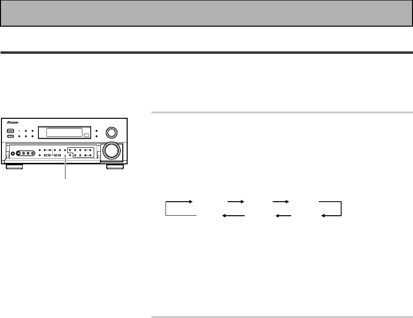
84
En
Press the VIDEO SELECT button on the front
panel to cycle through the different possible
video inputs.
The first press shows the video input you are currently using.
After that pressing VIDEO SELECT cycles though the possibili-
ties in the following order:
DVD/LD VCR1 VCR2
OFF VIDEO
TV/SAT
()
The OFF setting means the AUDIO and VIDEO source are the
same. (Also, if one of the MD/TAPE 1, CD, TUNER, or PHONO
functions are selected the VIDEO SELECT will be set to OFF.)
After choosing a video input the display on the receiver will
show that input for about 5 seconds and then revert to showing
the sound mode the receiver is in.
The VIDEO SELECT remains set to the input
you chose until you change the audio input.
If you change audio functions the receiver will reset itself to
make the video and audio inputs correspond.
Also, if you switch the power of the receiver OFF when you
turn it back on the video and audio inputs will reset so that they
correspond.
Video Select
This function allows you to listen to one sound source while you watch a different video source on your TV. The
sound source is set in the normal fashion as is explained on p.45-46. You then alter the video input with the
VIDEO SELECT button.
VIDEO SELECT
Using Other Functions
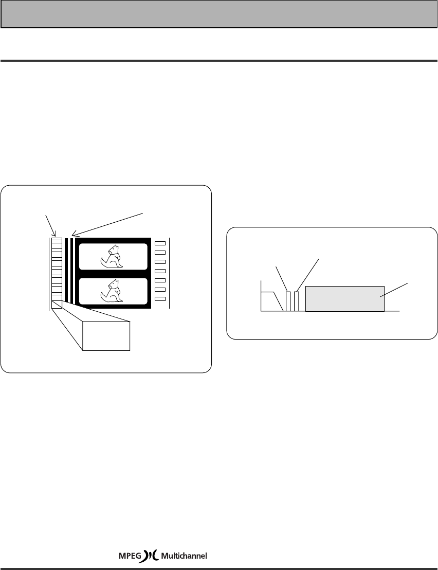
85
En
Techno Tidbits & Problem-solving
Dolby Digital
Digital
sound
2468101214 MHz
Frequency
Analog
sound
(Monaural)
Video
Dolby Digital
sound
Dolby Digital is a compression format which records
the sound of 6 channels of the theater surround
system (Dolby Digital) on the movie film digital track.
Of the 6 channels, the sub woofer channel is intended
for bass only, and because the frequency range is
smaller than the main channel, it is expressed as 5.1
channel.
Dolby Digital is the name of the Dolby surround multi-
channel digital system that was developed after the
Dolby Surround System and Dolby Pro Logic Surround
System.
The number of movies made using Dolby Digital since
1992 has exceeded 300 and continues to increase.
For compact disc players and laser disc digital sounds,
16 bits are used to sample the original analog audio
waveform and sampling is carried out 44,100 times
every second. However because an enormous
amount of recording signal data is required for the
multi channel system with this method, Dolby Digital
is used to compress the data.
In reproducing audio signals, the smaller the bit
number used, the lower the sound quality. With Dolby
Digital, drop in auditory sound quality is prevented by
using masking technology and digital filtering
technology based on the human auditory
characteristics.
Laser disc format
Laser discs are now available on the market in large
numbers. This means that the recording of different
format audio signals on the laser disc raises the
important question of compatibility with existing laser
discs. Dolby Digital tracks on laser discs record signals
using the space of one analog audio channel so it will
maintain compatibility with existing discs and players.
As shown in the following figure, the digital audio
sounds of Dolby Digital discs can be played back as
currently done. Analog sounds are played back by
using the other channel without the Dolby Digital
signals for monaural audio signals.
Comparison with Dolby Pro Logic
Surround
Dolby Digital is also known as the 5.1 channel system.
It is equipped with 5 channels (front left, front right,
center, surround left, surround right) in the frequency
range from 20 Hz to 20 kHz and an independent Low
Frequency Effect (LFE) channel. The subwoofer
channel is also called Low Frequency Effect (LFE).
The subwoofer channel can be used as desired to
enjoy strong bass sounds.
5.1 channel digital
surround track
4 channel analog sound
track (Matrix)
Dolby
Digital
encoding
Dolby Digital for movie films
MPEG Audio
MPEG is an audio encoding system which delivers high quality audio for music and movies. By removing
frequencies which are out of the human hearing range, the sound is then compressed to enable the
transmission of mono, stereo, or multichannel (5.1 and 7.1) audio in a single bitstream which is why it has
become a standard audio format for DVD and personal computers. The composition and versatility of MPEG
audio also ensures that the presentation of a multichannel soundtrack will sound appropriate on everything from
a 7.1 channel surround sound home theater setup to a mono television set. Above all, MPEG audio is designed
to be compatible with past and future MPEG audio versions, which means that future versions of MPEG audio
will be compatible with decoders currently being produced (the signal is merely reconfigured to fit the number of
channels available in a system).
1
86
En
DTS
DTS has been adopted as a sound recording format in the latest movie theaters since the release of “JURASSIC
PARK” in 1993, and has a good reputation for high quality sound and dynamic surround effects.
In this system, 6 channels of digital sound are recorded on CD-ROM, rather than on the film. DTS adopts a
simultaneous playback format. With a low rate of compression of sound signals and a high rate of transmittance,
a higher sound quality format is produced. Also, unlike the process of recording digital sounds on film directly,
the only components required are a CD-ROM player as might be used with a personal computer and a DTS
processor, and therefore less investment is required than with other formats. For this reason, the format is
being introduced in more and more movie theaters, and is being adopted in home movie software (DVD, LD)
and music software (5.1 channel CD). DTS has recently added a third surround channel to its system. This has
come to be known as DTS Extended Surround or simply DTS-ES.
Techno Tidbits & Problem-solving
R
THX
THX is a Lucasfilm, Ltd. program dedicated to maximum accuracy in movie presentation. Movie sound tracks
are recorded in large movie dubbing stages using movie theater equipment. For a sound track to be presented
accurately in your home, special technologies are required. In your home the room is much smaller and has a
bright sound, the speakers are very different and there are only six-eight of them, plus, you sit much closer to
each one of those speakers. Because of these differences we often miss the power and emotion that thrills
us in a good movie. Now Pioneer and THX have teamed up to bring the full glory of accurate cinema sound to
the comfort and convenience of your home.
Re-Equalization™ : In a theater the room is very large and dead sounding, you sit a long way back from the
speakers and the speakers themselves are very specialized. Because a sound track recorded in this dead
sounding space when it is played at home it sounds overbright. THX Re-Equalization adjusts for this difference
in a very precise way.
Adaptive Decorrelation™ : When a sound track sends mono sound to the surround speakers it often seems
to be coming come from one side instead of from all around you as it would in a theater. Adaptive
Decorrelation helps to correct this inaccuracy.
Timbre Matching™ : When recording a sound track it is very important that the surround sounds move
smoothly and seamlessly around the theater. It is very distracting when sounds seem to jump from speaker to
speaker. Timbre Matching helps to smooth the movement of the surround sounds even though you are using
only two speakers.
Bass Peak Level Manager™ : Some Dolby Digital sound tracks can produce bass peaks that are undesirable
in a home theater environment. The Bass Peak Level Manager allows you to set the maximum peak levels
appropriate to your system. (Set this function according to the Bass Peak Level instructions on page 39.)
Loudspeaker Position Time Synchronization™ : This feature allows you to adjust for the difference in the
distance from each individual loudspeaker to the listening position. Doing this ensures that all the speakers
operate in precise synchronization improving the seamless nature of the soundfield. (Set this function
according to the Channel Delay instructions on p.35.)
THX Surround EX™ : THX Surround EX–Dolby Digital Surround EX is a joint development of Dolby
Laboratories and the THX division of Lucasfilm Ltd.
In a movie theater, film soundtracks that have been encoded with Dolby Digital Surround EX technology are
able to reproduce an extra channel which has been added during the mixing of the program. This channel,
called Surround Back, places sounds behind the listener in addition to the currently available front left, front
center, front right, surround right, surround left and subwoofer channels. This additional channel provides the
opportunity for more detailed imaging behind the listener and brings more depth, spacious ambience and
sound localization than ever before.
Movies that were created using the Dolby Digital Surround EX technology, when released into the home
consumer market may exhibit a Dolby Digital Surround EX logo on the packaging. A list of movies created
using this technology can be found on the Dolby web site at http://www.dolby.com.
Only receiver and controller products bearing the THX Surround EX logo, when in the THX Surround EX mode,
faithfully reproduce this new technology in the home.
This product may also engage the "THX Surround EX" mode during the playback of 5.1 channel material that is
not
Dolby Digital Surround EX encoded. In such case the information delivered to the Surround Back channel
will be program dependent and may or may not be very pleasing depending on the particular soundtrack and
the tastes of the individual listener.
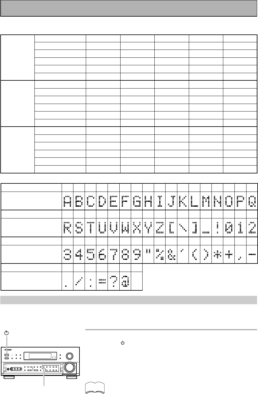
87
En
*1
*6
Station No.
Station Name
Frequency
Station No.
Station Name
Frequency
CLASS A
CLASS B
CLASS C
Station No.
Station Name
Frequency
Station No.
Station Name
Frequency
Station No.
Station Name
Frequency
Station No.
Station Name
Frequency
STATION CALL button “memo”
It is recommended that you make a note of the preset stations.
Character display used for station name input:
*1
*6
*1
*6
*2
*7
*2
*7
*2
*7
*3
*8
*3
*8
*3
*8
*4
*9
*4
*9
*4
*9
*5
*0
*5
*0
*5
*0
012
3456789
!
"%&' ( ) *+, -
./:=?@
ABCDE FGH I JKLMNOPQ
R
Character
Character
Character
Character
Display indications
Display indications
Display indications
Display indications
STUVWXYZ[\]_
Techno Tidbits & Problem-solving
Warning about DTS test mode
The receiver has a mode for PIONEER repairmen to test the DTS sound quality. You will never need to access
this mode. Rather, you should be careful NOT to put the receiver in this mode because doing so will erase all
your setup parameters like speaker settings, delay settings, channel settings, etc.
In STANDBY mode, holding the TAPE 2 MONITOR button and
pressing the STANDBY/ON button will put the receiver in
DTS test mode. Be careful NOT to do this.
The above described method is similar to choosing either PAL or NTSC
video setting and choosing 8 Ω or 6 Ω setting so be particularly careful
when performing these operations not to accidentally put the receiver in
DTS test mode.
If you accidentally put the receiver in DTS test mode, repeat the
same procedure (as above) to put the receiver back in a usable
mode. After this you will need to reset your setup parameters
(speaker settings, delay settings, channel settings, etc.).
memo
STANDBY/ON
TAPE 2
MONITOR
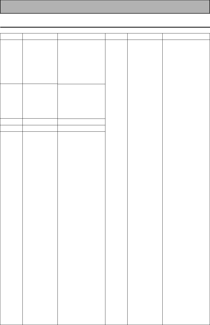
88
En
Preset Code List
Device
DVD
LD
STB(SAT)
STB(CATV)
VCR
Code
001
002
003
004
005
006
007
009
000, 008
110
109
108
108
101, 102
100
100, 111
200, 204
208
414, 428
432, 408
417, 449, 428
416, 417, 457, 458,
459
407, 417, 428
408, 414, 441, 453,
454, 455
442, 417
406, 417, 441
405, 409, 414, 417,
428
407, 409, 414
402
445, 446, 424
444
417, 449, 450
432, 408, 417, 455
442, 444, 417
417
446, 441
453
446, 447, 448, 452,
424
452
441
453
411, 414
444, 417, 441, 450
448, 452, 453
449, 451
417
446, 447, 448, 424,
453
452
441
453
452
452
Device
VCR
Manufacturer
CROWN
DAEWOO
DANSAI
DE GRAAF
DECCA
DUAL
DUMONT
ELCATECH
FIDELITY
FINLANDIA
FINLUX
FIRSTLINE
FISHER
FRONTECH
FUNAI
GBC
GENERAL
GOLDSTAR
GOODMANS
GRAETZ
GRANADA
GRANDIENTE
GRANDIN
HCM
HINARI
HYPSON
IMPERIAL
INTERFUNK
ITT
ITV
KAISUI
KENDO
KORPEL
LEYCO
LOEWE
LUXOR
M-ELECTRONIC
MANESTH
MARANTZ
MATSUI
MEMOREX
MEMPHIS
METZ
MINERVA
MULTITECH
MURPHY
NBC
NECKERMANN
NESCO
NORDMENDE
OCEANIC
OSAKI
OTTO VERSAND
PALLADIUM
PATHE MARCONI
PENTAX
PERDIO
Code
448, 452, 453
448, 452
453
406
414,441
417
444, 414, 441
453
441
444, 414
406, 444, 414, 441
405, 409, 411, 424,
453
444
452
441
414
452
411
411, 448, 441, 452,
453
444, 417
444, 414
441
411, 441, 453
453, 454
445, 446, 453, 454
453
441
414
442, 444, 417, 428
411, 448
453
444, 424
453
453
411, 414
442, 409, 444
441
405, 453
414
445, 446, 424
444, 411, 441
453
432, 455
455
441, 453
441
407, 417
414
453
417, 428
417, 441
411, 441, 453
414
411, 417, 453
417
406
441
Manufacturer
TOSHIBA
SONY
PANASONIC
JVC
SAMSUNG
SHARP
AKAI
RCA
PIONEER
DENON
HITACHI
PHILIPS
RADIOLA
SONY
TELEFUNKEN
PIONEER
PIONEER
PIONEER
PHILIPS
PANASONIC
THOMSON
SONY
JVC
GRUNDIG
AKAI
HITACHI
TOSHIBA
MITSUBISHI
SHARP
ORION
SANYO
FERGUSON
BLAUPUNKT
NOKIA
SELECO
AIWA
AKIBA
ALBA
AMBASSADOR
AMSTRAD
ANITECH
ASA
BAIRD
BASIC LINE
BRANDT
BRANDT
ELECTRONIQUE
BUSH
CATRON
CGB
CIMLINE
CLATRONIC
CONDOR
Techno Tidbits & Problem-solving

89
En
Device
VCR
DVD
Recorder
TAPE
Manufacturer
PHONOLA
PORTLAND
PROLINE
PYE
QUELLE
RADIOLA
REX
ROADSTAR
SABA
SAISHO
SALORA
SANSUI
SBR
SCHAUB LORENZ
SCHNEIDER
SEI
SENTRA
SHINTOM
SIEMENS
SINGER
SINUDYNE
SOLAVOX
SUNSTAR
SUNTRONIC
TASHIKO
TATUNG
TEC
TELEAVIA
TELEFUNKEN
TENOSAL
TENSAI
THORN
UNIVERSUM
YAMISHI
YOKAN
YOKO
PIONEER
PIONEER
AKAI
ARCAM
DENON
FISHER
GRUNDIG
JVC
KENWOOD
LUXMAN
MARANTZ
MEMOREX
MITSUBISHI
NAKAMICHI
ONKYO
PHILIPS
SANSUI
SHERWOOD
SONY
TANDBERG
TECHNICS
TOSHIBA
YAMAHA
PIONEER
Code
414
452
441, 454
414
414
414
417, 428
411, 448, 453
417, 449, 428
445, 424
442, 409
407, 417
414
417, 441
414, 441, 453
414
452
453
444, 411, 455
405
414
452
441
441
441
414, 417, 441
452
417
417, 449, 451, 428
453
441
444, 417
442, 411, 414, 441,
455
453
453
452
400, 443, 407, 414
456
829
810
810, 827
813
821
802
804, 807, 822
815
821
825
829
816
817, 819
821
824
818
814, 823
820
803
826, 828
811, 822
800, 825
Device
CD
CD-R
TV
Manufacturer
AKAI
ARCAM
ASUKA
AUDIO TON
BUSH
CALIFORNIA
AUDIO LAB
CYRUS
DENON
DUAL
FISHER
GOLDSTAR
GRUNDIG
HITACHI
INTERSOUND
JVC
KENWOOD
KODAK
LINN
LUXMAN
M ELECTRONIC
MARANTZ
MATSUI
MCS
MEMOREX
MERIDIAN
MITSUBISHI
NAD
NAIM
ONKYO
PANASONIC
PHILIPS
QUAD
QUASER
ROADSTAR
ROTEL
SABA
SANYO
SHARP
SONY
TECHNICS
TELEFUNKEN
THOMSON
UNIVERSUM
YAMAHA
PIONEER
PHILIPS
PIONEER
PHILIPS
SONY
GRUNDIG
PANASONIC
TOSHIBA
TELEFUNKEN
SHARP
SAMSUNG
HITACHI
SABA
BRANDT
SANYO
Code
335
336
337
336
332
304
336
309
337, 319
340
330
336
334
337
331
310, 311
322
336
341
344
304, 336
336
304
300
336
335
316
336
342
304
336, 322
336
304
344
336
319
340
343
329, 316
304, 333
319
319
336
338, 339
300
346
345
631, 607, 634, 656
604
631, 653
631, 608, 642, 622
605, 653
636, 637, 652
602
607, 638, 644, 646
631, 633, 634, 636,
642, 643, 654, 606
631, 636, 642, 651
636
635, 645, 648
Techno Tidbits & Problem-solving

90
En
Device
TV
Manufacturer
THOMSON
FERGUSON
NOKIA
MITSUBISHI
SCHNEIDER
GOLDSTAR
BLAUPUNKT
NORDMENDE
RADIOLA
JVC
DAEWOO
ORION
SIEMENS
ACURA
ADMIRAL
AKAI
AKURA
ALBA
AMSTRAD
ANITECH
ASA
ASUKA
AUDIOGONIC
BASIC LINE
BAUR
BEKO
BEON
BLUE SKY
BLUE STAR
BPL
BTC
BUSH
CASCADE
CATHAY
CENTURION
CGB
CIMLINE
CLARIVOX
CLATRONIC
CONDOR
CONTEC
CROSLEY
CROWN
CRYSTAL
CYBERTRON
DAINICHI
DANSAI
DAYTON
DECCA
DIXI
DUMONT
ELIN
ELITE
ELTA
EMERSON
ERRES
FINLANDIA
FINLUX
FIRSTLINE
FISHER
Code
636, 651, 652
607, 636, 651
632, 642, 652
631, 609
607, 641, 647
607, 650
631
632, 636, 651, 652
607
613
607, 644, 656
632, 607, 639, 640
631
644
631
632, 635, 642
641
607, 639, 641, 644
642, 644, 647
644
645
641
607, 636
641, 644
631, 607, 642
638
607
641
618
618
641
607, 641, 642, 644,
647, 656
644
607
607
642
644
607
638
638
644
632
638, 644
642
641
641
607
644
607, 648
607, 644
653
607
641
644
642
607
635, 643, 655
632, 607, 645, 648,
653, 654, 655
640, 644
632, 635, 638, 645
Device
TV
Manufacturer
FORMENTI
FRONTECH
FRONTECH/
PROTECH
FUJITSU
FUNAI
GBC
GEC
GELOSO
GENEXXA
GOODMANS
GORENJE
GPM
GRAETZ
GRANADA
GRANDIENTE
GRANDIN
HANSEATIC
HCM
HINARI
HISAWA
HUANYU
HYPSON
ICE
IMPERIAL
INDIANA
INGELEN
INTERFUNK
INTERVISION
ISUKAI
ITC
ITT
JEC
KAISUI
KAPSCH
KENDO
KENNEDY
KORPEL
KOYODA
LEYCO
LIESENK&TTER
LUXOR
M ELECTRONIC
M-ELECTRONIC
MAGNADYNE
MAGNAFON
MANESTH
MARANTZ
MARK
MATSUI
MCMICHAEL
MEDIATOR
MEMOREX
METZ
MINERVA
MULTITECH
NECKERMANN
Code
632, 607, 642
631, 642, 646
632
648
640, 646
632, 642
607, 634, 648
632, 644
631, 641
607, 639, 647, 648,
656
638
641
631, 642
607, 635, 642, 643,
648
657
618
607, 642
618, 644
607, 641, 644
618
656
607, 618, 646
646, 647
638, 642
607
631
631, 632, 607, 642
646, 649
641
642
631, 632, 642
605
618, 641, 644
631
642
632, 642
607
644
607, 640, 646, 648
607
632, 642, 643
631, 644, 645, 654,
655, 656
607, 636, 651
632, 649
649
639, 646
607
607
607, 639, 640, 642,
644, 647, 648
634
607
644
631
631, 653
644, 649
631, 607
Techno Tidbits & Problem-solving
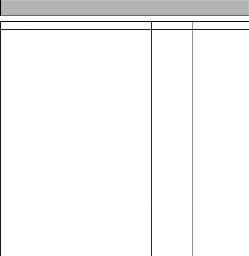
91
En
Device
TV
Manufacturer
NEI
NIKKAI
NOBLIKO
OCEANIC
OSAKI
OSO
OSUME
OTTO VERSAND
PALLADIUM
PANAMA
PATHO CINEMA
PAUSA
PHILCO
PHOENIX
PHONOLA
PROFEX
PROTECH
QUELLE
R-LINE
RBM
REDIFFUSION
REX
ROADSTAR
SAISHO
SALORA
SAMBERS
SBR
SCHAUB
LORENZ
SEG
SEI
SELECO
SIAREM
SINUDYNE
SKANTIC
SOLAVOX
SONOKO
Code
607, 642
605, 607, 641, 646,
648
649
631, 632, 642
641, 646, 648
641
648
631, 632, 607, 642
638
646
642
644
632, 642
632
607
642, 644
607, 642, 644, 646,
649
631, 632, 607, 642,
645, 653
607
653
632, 642
631, 646
641, 644, 646
639, 644, 646
631, 632, 642, 643
649
607, 634
642
642, 646
632, 640, 649
631, 642
632, 649
632, 639, 640, 649
643
631
607, 644
Device
TV
MD
TUNER
Manufacturer
SONOLOR
SONTEC
SOUNDWAVE
STANDARD
STERN
SUSUMU
SYSLINE
TANDY
TASHIKO
TATUNG
TEC
TELEAVIA
TELETECH
TENSAI
THORN
TOMASHI
TOWADA
ULTRAVOX
UNIVERSUM
VESTEL
VOXSON
WALTHAM
WATSON
WATT RADIO
WHITE
WESTINGHOUSE
YOKO
PIONEER
SONY
KENWOOD
SHARP
TEAC
ONKYO
DENON
PIONEER
PIONEER
Code
631, 635
607
607
641, 644
631
641
607
631, 641, 648
634
607, 648
642
636
644
640, 641
631, 607, 642, 645,
648
618
642
632, 642, 649
631, 607, 638, 642,
645, 646, 654, 655
607
631
643
607
632, 642, 649
607
607, 642, 646
672, 631, 632, 607,
636, 642, 651
901
903
902
904
905
906
900, 902, 907(DAT)
500
Techno Tidbits & Problem-solving
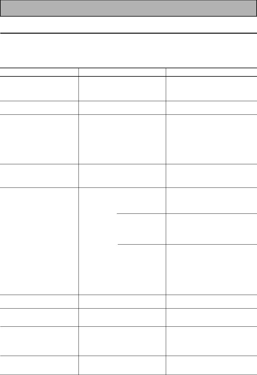
92
En
Troubleshooting
Incorrect operations are often mistaken for trouble and malfunctions. If you think that there is something wrong with
this component, check the points below. Sometimes the trouble may lie in another component. Investigate the other
components and electrical appliances being used. If the trouble cannot be rectified even after exercising the checks
listed below, ask your nearest PIONEER authorized service center or your dealer to carry out repair work.
Techno Tidbits & Problem-solving
Cause
• The power plug is disconnected.
• The protection circuit may have
been activated.
• Static electricity caused by dry air.
• Improper connections.
• Sound is muted.
• The volume is turned down.
• The TAPE 2 MONITOR is ON.
• Speakers are turned OFF.
• DIGITAL/ANALOG switch is set
incorrectly.
• Improper connections.
• The input source is not properly
selected.
• Incorrect frequency.
• The antenna is not connected.
•2 RF and/or digital cables are near
the antenna terminals and wires.
FM broadcasts
• The FM antenna is not fully
extended or is poorly positioned.
• Weak radio signals.
AM broadcasts
• The AM antenna is poorly
positioned.
• Weak radio signals.
• Interference caused by other
equipment (fluorescent lamp,
motor, etc.).
• Weak radio signals.
• Settings route signal away from sub
woofer.
• The LD is not a Dolby Digital
compatible disc.
• The Dolby Digital / DTS source is
not 5 channels.
Symptom
The power does not turn ON.
The unit does not respond when
the buttons are pressed.
No sound is output when a
function is selected.
No image is output when a
function is selected.
Considerable noise in radio
broadcasts.
Broadcast stations cannot be
selected automatically.
Subwoofer output is very low.
When playing an LD the SIGNAL
SELECT is on 2 RF but there is
still no sound.
When playing a Dolby Digital / DTS
source the 5.1 Channel indicator
doesn't light.
Remedy
• Connect the power plug to the wall
outlet.
• Disconnect the power plug from the
outlet, and insert again.
• Disconnect the power plug from the
outlet, and insert again.
• Make sure the component is
connected correctly (see p.12-21).
• Press MUTE on the remote control.
• Adjust MASTER VOLUME.
• Press the TAPE 2 MONITOR button.
• Press SPEAKERS (A/B) to select the
speakers you connected.
• Set SIGNAL SELECT (see p.48).
• Make sure the component is
connected correctly (see p.15-18).
• Press the correct function button.
• Tune in the correct frequency.
• Connect the antenna (see p.18).
• Route 2 RF and digital cables away
from the antenna terminals and wires.
• Fully extend the FM wire antenna,
position for best reception, and
secure to a wall.
• Connect an outdoor FM antenna (see
p.18).
• Adjust the direction and position for
best reception.
• Connect an additional internal or
external AM antenna (see p.18).
• Turn off the equipment causing the
noise or move it away from the
receiver.
• Place the antenna farther away from
the equipment causing the noise.
• Connect an outdoor antenna (see
p.18).
• To get more signal to the subwoofer
set it to PLUS or choose SMALL for
the FRONT speakers (see p.33-34).
• Set the SIGNAL SELECT to analog
(make sure your LD player is hooked
up with analog connections in addition
to digital and 2 RF connections, see
p.14).
• There is no problem with the receiver
but if you want 5 channel sound you
must play a 5 channel source.

93
En
Techno Tidbits & Problem-solving
Cause
• Speaker settings are incorrect.
• The rear and/or center levels are
turned down.
• The surround and/or center
speakers are disconnected.
• SIGNAL SELECT is set incorrectly.
• The digital inputs are assigned
incorrectly, or not at all.
• SIGNAL SELECT is set to
“ANALOG”.
• A DVD player not compatible with
DTS is used, or the setting of the
DVD player is incorrect.
• The digital output level has been
turned down on a CD player or
other component equipped with
digital output level adjustment
capability. (The DTS signal has been
altered by the player, and cannot be
read.)
• The speakers are tunred OFF.
• Disc being played back has a huge
amount of information on it.
• The search function performed by
the player interferes with the
reading of digital information.
• The remote control batteries have
worn out.
• Too far away or bad angle of
operation.
• There is an obstacle between the
receiver and the remote control.
• Strong light such as fluorescent
light is shining onto the unit's
remote control signal light-receiving
window.
• A cord is connected to the
CONTROL IN terminal on this unit.
• The IR -Receiver type is
mismatched with the setting.
•The FL DIMMER button is pushed.
• If you are using an analog source,
the signal is too strong.
• If you are using a digital source,
there is too much information for
the receiver to handle.
• The SIGNAL SELECT is on
ANALOG.
Remedy
• See “SPEAKER SETTING” on p.33-34
to check the speaker settings.
• See “CHANNEL LEVEL” p.36-37 to
check the speaker levels.
• Connect the speakers (see p.19).
• Set SIGNAL SELECT to “AUTO” or
according to the type of connections
made (see p.48).
• Set the digital input settings correctly
(see p.32).
• Make digital connections (see p.13)
and set SIGNAL SELECT to “AUTO”
(see p.48).
• Refer to the instruction manual
supplied with the DVD player.
• Set the digital volume level of the
player to full, or to the neutral
position.
• Turn the speakers ON.
• Use the STANDARD mode to get
the best results (see p.45).
• This is not a malfunction, but be sure
to turn the volume down to prevent
the output of loud noise from your
speakers.
• Replace the batteries (see p.9).
• Operate within 7 m, 30° of the remote
sensor on the front panel (see p.10).
• Remove the obstacle or operate from
another position.
• Avoid exposing the remote sensor on
the front panel to direct light.
• Connect cord to the correct jack.
• Disconnect the IR Receiver from the
rear panel, and set to the other IR
Receiver type using the remote
control.
• Press FL DIMMER on the front panel
repeatedly to return to the default
setting (see p.53).
• Press the INPUT ATT button (see
p.22).
• For 2/DTS sources put the receiver
in STANDARD mode (see p.45).
• Set the SIGNAL SELECT to DIGITAL.
Symptom
No sound from surround or
center speakers.
Sound is produced from some
components, but not from
digital components.
No sound is output or a noise is
output when software with DTS
is played back.
The sound is output
intermittently when software
with DTS is played back.
When a search is performed by
a DTS compatible CD player
during playback, noise is output.
Cannot be remote controlled.
The display is dark.
The OVER indicator is
constantly lit.
When playing a Dolby Digital /
DTS format LD there is noise
audible on the soundtrack.
94
En
Techno Tidbits & Problem-solving
Cause
• Either the digital connections or the
DIGITAL IN SELECT choices are
incorrect.
• The TAPE2 MONITOR mode is ON.
• You are not using a source with
Surround EX flag.
• The player is paused or stopped.
• There is a mistake in the player
settings for audio output.
• Although it's a Dolby Digital / DTS
source there is a possibility the
present track is not Dolby Digital /
DTS.
Remedy
• Make sure the digital connections and
the DIGITAL IN SELECT choices are
done correctly.
• Press the TAPE2 MONITOR button so
it goes into the OFF setting.
• There is no problem with your
receiver but if you want to hear 7
channel sound use an Surround EX
source.
• Play the source.
• Fix the audio settings (check the
manual that came with your DVD
player.
• There is no problem. The indicator
won't light when the track is not a
Dolby Digital / DTS track.
Symptom
You can't get DIGITAL to come
up when using the SIGNAL
SELECT button.
When using THX AUTO mode
the receiver is not playing in the
EX mode.
The Dolby Digital / DTS
indicator doesn't light up even
when playing a Dolby Digital /
DTS source.
If the unit does not operate normally due to external effects such as static electricity
Disconnect the power plug from the outlet and insert again to return to normal operating conditions.

95
En
FM Tuner Section
Frequency Range ......................... 87.5 MHz to 108 MHz
Usable Sensitivity ...... Mono: 15.2 dBf, IHF (1.6 µV/75 Ω)
50 dB Quieting Sensitivity .......................Mono: 20.2 dBf
Stereo: 41.2 dBf
Sensitivity (DIN) ...................... Mono: 1.1 µV (S/N 26 dB)
Stereo: 50 µV (S/N 46 dB)
Signal-to-Noise Ratio ................. Mono: 76 dB (at 85 dBf)
Stereo: 72 dB (at 85 dBf)
Signal-to-Noise Ratio (DIN) .......................... Mono: 62 dB
Stereo: 58 dB
Distortion ...................................... Stereo: 0.6 % (1 kHz)
Alternate Channel Selectivity ................. 70 dB (400 kHz)
Stereo Separation ...................................... 40 dB (1 kHz)
Frequency Response ................ 30 Hz to 15 kHz (± 1dB)
Antenna Input .......................................75 Ω unbalanced
AM Tuner Section
Frequency Range .......................... 531 kHz to 1.602 kHz
Sensitivity (IHF, Loop antenna) ......................... 350 µV/m
Selectivity ............................................................... 30 dB
Signal-to-Noise Ratio .............................................. 50 dB
Antenna ...................................................... Loop antenna
Miscellaneous
Power Requirements
UK model ...................................... AC 230 V, 50/60 Hz
European model ................... AC 220 - 230 V, 50/60 Hz
Power Consumption ............................................. 400 W
Power Consumption in Standby mode .................. 1.0 W
AC Outlets (except for the UK model)
SWITCHED (×2) ...............................Total 100 W MAX.
UNSWITCHED ........................................ 100 W MAX.
Dimensions .................. 420 (W) × 173 (H) × 470 (D) mm
Weight (without package) .................................... 16.2 kg
Furnished Parts
FM wire antenna ............................................................1
AM loop antenna ............................................................1
“AA” IEC LR6 batteries ................................................. 2
Remote control unit ....................................................... 1
Operating Instructions ................................................... 1
NOTE:
Specifications and the design are subject to possible
modifications without notice, due to improvements.
Amplifier Section
Continuous Power Output (STEREO MODE)
FRONT .... 110 W + 110 W (DIN 1 kHz, THD 1 %, 8Ω)
Continuous Power Output (SURROUND MODE)
FRONT .... 110 W + 110 W (DIN 1 kHz, THD 1 %, 8Ω)
CENTER ................. 110 W (DIN 1 kHz, THD 1 %, 8Ω)
SURROUND ....................................... 110 W + 110 W
(DIN 1 kHz, THD 1 %, 8Ω)
Rated Power Output .............................. 100 W + 100 W
(20 Hz to 20 kHz, THD 0.09 %, 8Ω)
•
Above specifications are applicable when the power
supply is 230V.
Audio Section
Input (Sensitivity/Impedance)
PHONO MM ..........................................4.7 mV/47 kΩ
VCR 1/DVR, VCR 2, DVD/LD, TV/SAT, VIDEO, CD,
MD/TAPE 1/CD-R, TAPE 2 ..................... 335 mV/47 kΩ
Frequency Response
PHONO MM ........................ 20 Hz to 20 kHz ±0.3 dB
VCR 1/DVR, VCR 2, DVD/LD, TV/SAT, VIDEO, CD,
MD/TAPE 1/CD-R, TAPE 2 ..... 5 Hz to 100,000 Hz dB
Output (Level/Impedance)
VCR 1/DVR REC, VCR 2 REC, MD/TAPE 1/CD-R REC,
TAPE 2 REC ............................................ 335 mV/1 k Ω
Tone Control
BASS ...................................................± 6 dB (100 Hz)
TREBLE ............................................... ± 6 dB (10 kHz)
LOUDNESS ........................... +10 dB (100 Hz/10 kHz)
Signal-to-Noise Ratio (IHF, short circuited, A network)
PHONO MM ...................................................... 80 dB
VCR 1/DVR, VCR 2, DVD/LD, TV/SAT, VIDEO, CD,
MD/TAPE 1/CD-R, TAPE 2 ................................ 101 dB
Signal-to-Noise Ratio [DIN Rated/50mW]
PHONO MM ................................................. 68/61 dB
VCR 1/DVR, VCR 2, DVD/LD, TV/SAT, VIDEO, CD,
MD/TAPE 1/CD-R, TAPE 2 ............................. 92/65 dB
Phono Overload Level (T.H.D. 0.1%, 1 kHz)
PHONO MM ................................................... 120 mV
Video Section
Input (Sensitivity/Impedance) ........................1 Vp-p/75 Ω
Output (Level/Impedance) ............................ 1 Vp-p/75 Ω
Signal-to-Noise Ratio .............................................. 65 dB
Frequency Response ..................... 5 Hz to 10 MHz dB
Component Video Section
Input (Sensitivity) .......................................... 1 Vp-p/75 Ω
Output (Level/Impedance) ............................ 1 Vp-p/75 Ω
Signal-to-Noise Ratio .............................................. 65 dB
Specifications
+0
–3
+0
–3

<ARB7234-A>
Printed in Japan
<00E00ZF0P00>
Published by Pioneer Corporation.
Copyright © 2000 Pioneer Corporation.
All rights reserved.
PIONEER CORPORATION
4-1, Meguro 1-Chome, Meguro-ku, Tokyo 153-8654, Japan
PIONEER ELECTRONICS [USA] INC.
P.O. BOX 1540, Long Beach, California 90801-1540, U.S.A.
PIONEER ELECTRONICS OF CANADA, INC.
300 Allstate Parkway, Markham, Ontario L3R OP2, Canada
PIONEER EUROPE NV
Haven 1087, Keetberglaan 1, B-9120 Melsele, Belgium TEL: 03/570.05.11
PIONEER ELECTRONICS AUSTRALIA PTY. LTD.
178-184 Boundary Road, Braeside, Victoria 3195, Australia, TEL: [03] 9586-6300
PIONEER ELECTRONICS DE MEXICO S.A. DE C.V.
San Lorenzo 1009 3er Piso Desp. 302 Col. Del Valle Mexico D.F. C.P. 03100
TEL: 5-688-52-90
