Pioneer Vsa E08 ARB7233 A User Manual To The E54a9c39 1e68 4cab 9303 3d014f12632c
User Manual: Pioneer vsa-e08 to the manual
Open the PDF directly: View PDF ![]() .
.
Page Count: 78

2
En
IMPORTANT 2
Do not connect either wire to the earth terminal of a
three - pin plug.
NOTE
After replacing or changing a fuse, the fuse cover in the
plug must be replaced with a fuse cover which corre-
sponds to the colour of the insert in the base of the plug
or the word that is embossed on the base of the plug, and
the appliance must not be used without a fuse cover. If
lost replacement fuse covers can be obtained from:
your dealer.
Only 5 A fuses approved by B.S.I. or A.S.T.A. to B.S.
1362 should be used.
The cut-off plug should be disposed of and must not be
inserted into any 13 amp socket as this can result in electric
shock. The plug or adaptor or the distribution panel should
be provided with 5 amp fuse. As the colours of the wires in
the mains lead of this appliance may not correspond with
coloured markings identifying the terminals in your plug,
proceed as follows :
The wire which is coloured blue must be connected to the
terminal which is marked with the letter N or coloured black.
The wire which is coloured brown must be connected
to the terminal which is marked with the letter L or coloured
red.
FOR USE IN THE UNITED
KINGDOM
The wires in this mains lead are coloured in
accordance with the following code :
Blue : Neutral
Brown : Live
If the plug provided is unsuitable for your socket
outlets, the plug must be cut off and a suitable plug
fitted.
RISK OF ELECTRIC SHOCK
DO NOT OPEN
CAUTION
IMPORTANT 1
CAUTION:
TO PREVENT THE RISK OF ELECTRIC SHOCK, DO
NOT REMOVE COVER (OR BACK). NO USER-
SERVICEABLE PARTS INSIDE. REFER SERVICING TO
QUALIFIED SERVICE PERSONNEL.
The exclamation point within an equilateral triangle is
intended to alert the user to the presence of important
operating and maintenance (servicing) instructions in
the literature accompanying the appliance.
The lightning flash with arrowhead symbol, within an
equilateral triangle, is intended to alert the user to the
presence of uninsulated "dangerous voltage" within the
product's enclosure that may be of sufficient magnitude
to constitute a risk of electric shock to persons.
Thank you for buying this Pioneer product.
Please read through these operating instructions
so you will know how to operate your model prop-
erly. After you have finished reading the instruc-
tions, put them away in a safe place for future ref-
erence.
In some countries or regions, the shape of the
power plug and power outlet may sometimes dif-
fer from that shown in the explanatory drawings.
However, the method of connecting and operat-
ing the unit is the same.
Power cord CAUTION!
Handle the power cord by the plug. Do not pull
out the plug by tugging the cord and never
touch the power cord when your hands are
wet as this could cause a short circuit or
electric shock. Do not place the unit, a piece of
furniture, etc., on the power cord, or pinch the
cord. Never make a knot in the cord or tie it
with other cords. The power cords should be
routed such that they are not likely to be
stepped on. A damaged power cord can cause
a fire or give you an electrical shock. Check the
power cord once in a while. When you find it
damaged, ask your nearest PIONEER
authorized service center or your dealer for a
replacement.
WARNING: TO PREVENT FIRE OR SHOCK
HAZARD, DO NOT EXPOSE THIS APPLIANCE TO RAIN
OR MOISTURE.
THE ON/OFF BUTTON IS SECONDARY
CONNECTED AND THEREFORE DOES NOT
SEPARATE THE UNIT FROM MAINS POWER IN
STANDBY POSITION.
This product complies with the Low Voltage
Directive (73/23/EEC), EMC Directives (89/336/EEC,
92/31/EEC) and CE Marking Directive (93/68/EEC).
[For European model]
If the socket outlets on the associated
equipment are not suitable for the plug supplied
with the product the plug must be removed and
appropriate one fitted.
The cut-off plug must be disposed of as an
electrical shock hazard could exist if connected
to a socket outlet.
Maintenance of External Surfaces
• Use a polishing cloth or dry cloth to wipe off dust and dirt.
• When the surfaces are dirty, wipe with a soft cloth dipped in some neutral cleanser diluted five or six times
with water, and wrung out well, and then wipe again with a dry cloth. Do not use furniture wax or cleansers.
• Never use thinners, benzine, insecticide sprays or other chemicals on or near this unit, since these will corrode
the surfaces.
III
En
Quick Start Guide
This is a quick guide to setting up your new amplifier so you can get home theater surround sound. For more
details on any of the information presented here check the main section of the manual.
Before making or changing the connections,switch off the power and disconnect the power cord from the AC
outlet.
11
11
1 Hooking Up Your DVD Player & TV
In order to use Dolby Digital/DTS soundtracks which are at the heart of home theater you need to hook up your
DVD player with digital audio connections. You can do this by either a coaxial or an optical connection, you don’t
need to do both. The quality of these two types of connections is the same but since some digital components
only have one type of digital terminal you need to figure out which yours has and hook it up to the appropriate
terminal on the amplifier. In order to do this you will need the proper cable. For coaxial connections you can use
a regular RCA stereo cord or the specially-made coaxial cords, they have the same type of plugs. For optical
connections you will need a special optical cord which you can buy at your local stereo store. Also hook up the
video connection of your DVD player, the analog audio (for recording the audio on DVDs, use regular RCA stereo
cords), and your TV (it's easiest to use a regular composite RCA video cords) as shown below. It is important
that you hook up your TV (or monitor) in order to see a video image as well as the on screen displays (OSDs)
shown by this amplifier (for more on p. 16-17). We also recommend hooking up your all your digital components
to analog audio jacks. For this you can use regular RCA stereo cords.
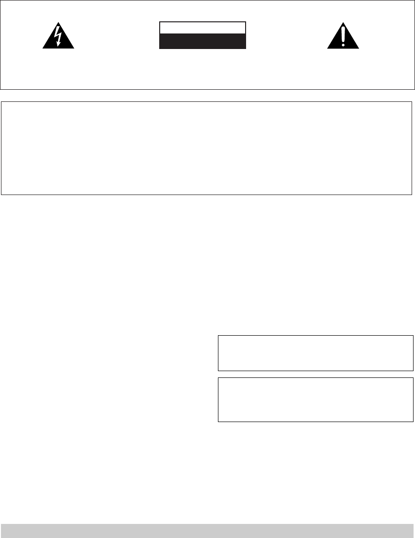
Coaxial Digital Connection
If your DVD player has a coaxial terminal (not a PCM-only output) for the audio out hook it up using this terminal.
Follow the diagram below. This is the best scenario, as you will be able to follow the default settings of this
amplifier and won't need to assign the digital inputs.
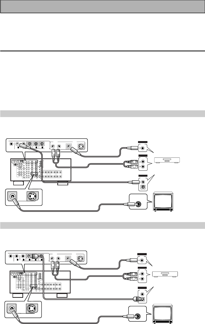
Optical Digital Connection
If your DVD player has a optical terminal (not a PCM-only output) for the audio out you can hook it up using this
following the below diagram. You will need to assign the digital input (tell the amplifier which input you put your
DVD digital audio into). See page V for this.
(not a PCM-only output)
(not a PCM-only output)
DVD player
OUTPUT
DIGITAL
STEREO
L
R
ANALOG
VIDEO
OUT
VIDEO
VIDEO INPUT
DVD /
LD
IN
S2 VIDEOVIDEO VIDEOAUDIO
IN
IN
5
IN
4
IN
3
2
RF IN
(AC-3) IN
2
IN
1
PCM/
2
/
DTS
DIGITAL
MONITOR
OUT1
L
R
L
R
RCA video cord
RCA video cord
RCA stereo cord
coaxial cord
DVD player
OUTPUT
DIGITAL
STEREO
L
R
ANALOG
VIDEO
OUT
VIDEO
VIDEO INPUT
DVD /
LD
IN
S2 VIDEOVIDEO VIDEOAUDIO
IN
IN
5
IN
4
IN
3
2
RF IN
(AC-3) IN
2
IN
1
PCM/
2
/
DTS
DIGITAL
MONITOR
OUT1
L
R
L
R
RCA video cord
RCA video cord
RCA stereo cord
optical cord
IV
En
Quick Start Guide
22
22
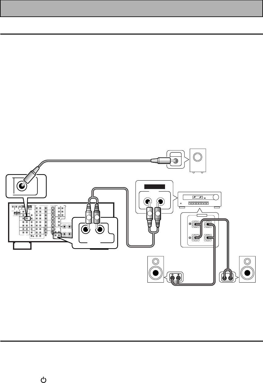
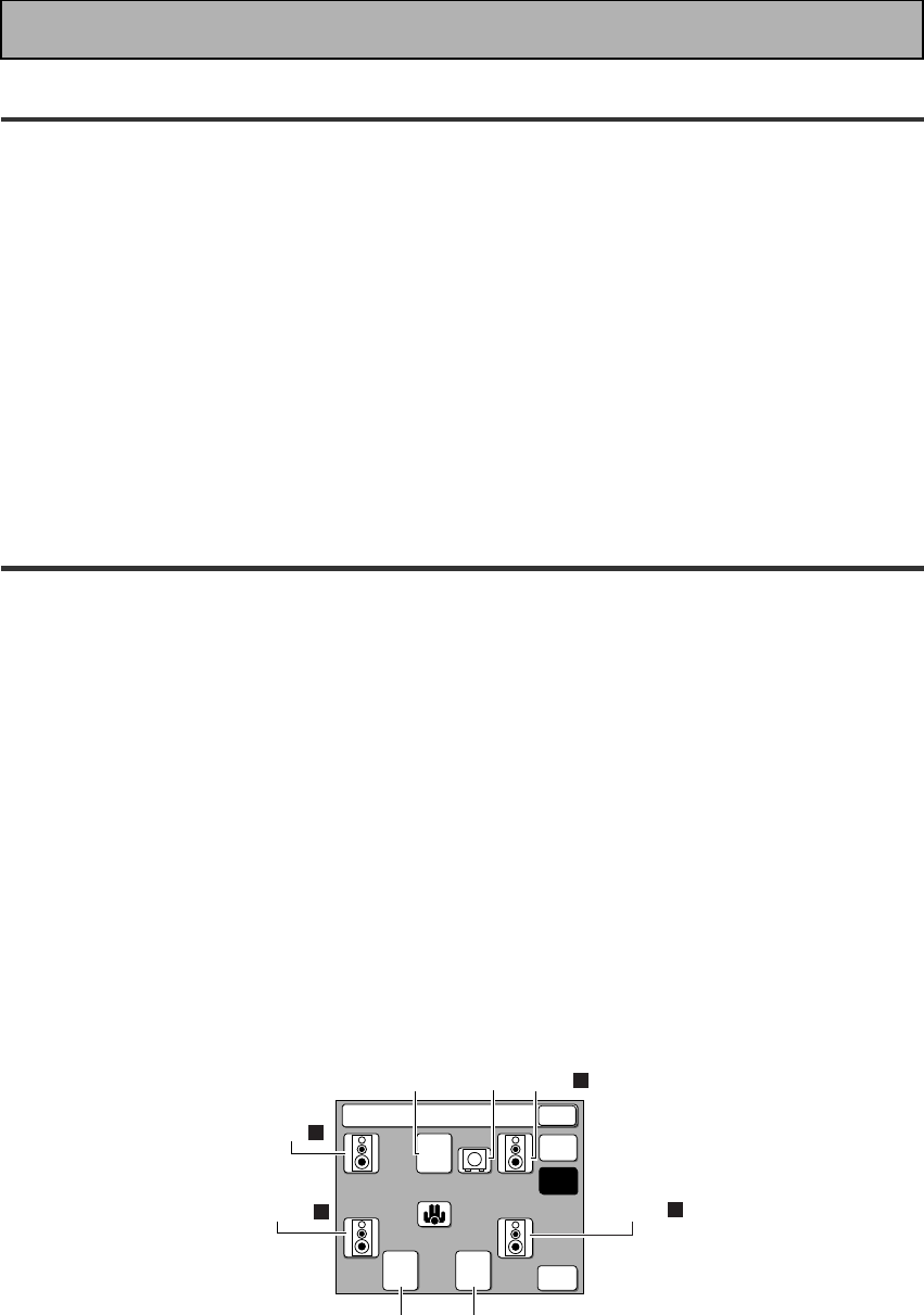
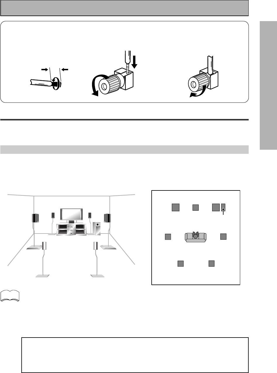
2 Speaker Connections
Home theater is designed to be setup with five, or seven speakers (front left & right; center; surround left &
right; and, optimally, surround back left & right) and a subwoofer but you can use this amplifier with fewer
speakers. Hook up the speakers you have to the A speaker terminals on the back of the amplifier. If you only
have two speakers hook them up as "FRONT." If you have three hook up the single speaker as "CENTER." Follow
the diagram on p. 19 in order to hook up all your speakers. A center speaker is very important for watching films
because the dialog comes from the center speaker in digital soundtracks. If you do not have a CENTER
speaker you must tell the amplifier the CENTER channel is OFF or when you listen to digital soundtracks
you won't hear any dialog. Use the instructions on page 32-33 in order to do this.
Follow the diagram below to hook up an additional amplifier in order to use surround back speakers. These
speakers are important to hear all the sound channels on new, eight channel home theater DVDs. The diagram
below also explains how to hook up a subwoofer which provides realistic bass sounds.
Make sure you connect the speaker on the right to the right terminal and the speaker on the left to the left
terminal. Also make sure the positive and negative (+/–) terminals on the amplifier match those on the speakers.
33
33
3 Setting up the Remote Control & Unit
1 Put the batteries in the REMOTE CONTROL.
2 Plug the main unit into a wall outlet.
3 Press the STANDBY/ON button to put the amplifier in ON mode.
RL (Single)
SURROUND
BACK
PRE OUT
SUB
WOOFER
Surround back
speaker (Right)
Surround back
speaker (Left)
INPUT Powered
sub-woofer
Additional Amplifier (See p.20)
INPUT L
L
R
R
ANALOG
FRONT
SPEAKERS
L
LR
R
RCA stereo cord
RCA audio cord
V
En
Quick Start Guide
4
System Setup
SPEAKER
SETTING CROSSOVER
NETWORK
BASS PEAK LEVEL
MANAGER
DYNAMIC RANGE
CONTROL
DIGITAL INPUT
SELECT
CHANNEL DELAY
CHANNEL LEVEL
BACK
44
44
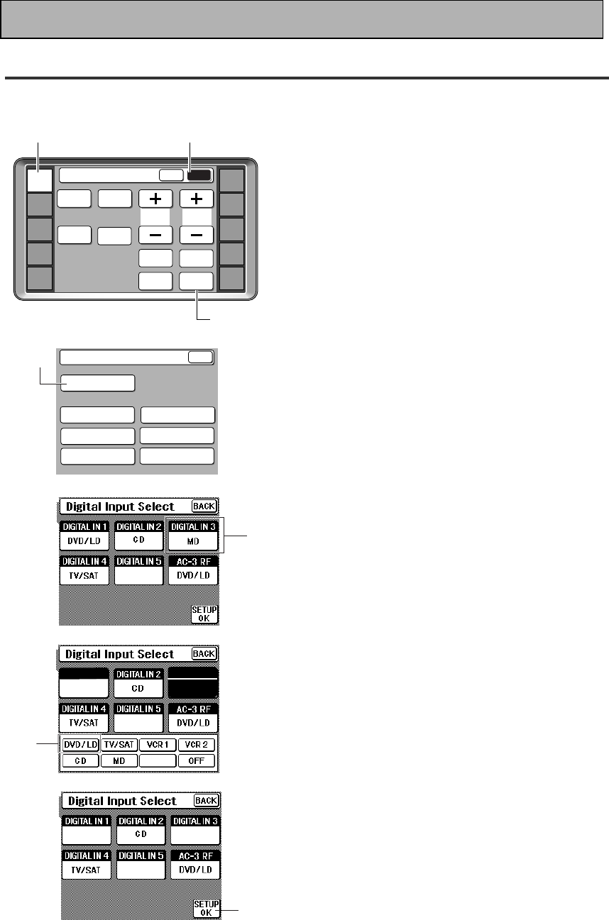
4 Digital Input Assignment
This is only necessary if you did not hook up your DVD to DIGITAL IN 1, as in the first diagram on p. III.
3
1 Turn on the amplifier and your TV,
press the AMP button on the
remote control.
2 Press the SUB button on the
remote control.
3 Press the SYSTEM SETUP button.
4 Press the DIGITAL INPUT SELECT
button.
5 Press the DIGITAL IN 3 button
which should correspond to the
digital in jack you hooked your DVD
up to (as in the optical digital
connection diagram on p. III),
6 At the bottom of the remote
control the functions available will
appear. Press the DVD/LD button.
7 Press the SETUP OK button.
Hold the remote control pointed towards the
amplifier until you see the “RECEIVED” display on
the amplifier.
If "ERROR" flashes in the display, perform the setup
operations from the first step again.
5
AMP
DVD/LD
TV/SAT
VCR1
VCR2
REMOTE
SETUP
MD/TAPE1
CD
LINE/
TUNER
TV
CONTROL
SPEAKER
A/B
TONE CH
SELECT
Amplifier
MAIN SUB
TREBLE
SYSTEM
SETUP
CH
LEVEL
INPUT
ATT.
BASS
FL
DIMMER
TAPE 2
MONITOR
6
7
VCR1
OFF DVD/LD
VCR1
LINE
DIGITAL IN 3
MD
DIGITAL IN 1
DVD
VCR1
12
VI
En
Quick Start Guide
55
55
5 Playing a DVD with Surround Sound
1 Turn on the Amplifier, your TV, and the DVD player.
2 Press the STANDARD button on the front panel for the basic surround
sound setting.
You can also press the remote control AMP button and then press the STANDARD button on that
Amplifier MAIN screen.
3 Press the DVD/LD button on the remote control.
You should see "DVD/LD" in the display on the amplifier.
4 Play a DVD.
66
66
6 For Better Surround Sound
1 Go through the entire "system setup" procedures as outlined on pages
30-39 of this instruction manual.
If you don't hook up any other components with digital audio or do so following the default settings of
the amplifier (see p.14) you won't have to assign any more digital inputs, but many other adjustments
will improve the sound tremendously.
2 Experiment with the different sound settings offered with the 2/DTS/
MPEG and DSP buttons.
For more information see p.41-45.
3 As mentioned above you should go through the "speaker setup" instructions
on pages 30-39 to set up your speakers properly. If you don't do this you, at
least, need to make sure the CENTER channel is turned off if you don't have a
center speaker. Use the instructions on pages 30-33 to get the display below
on your remote control.
If you don't have a center speaker press the CENTER button until the box
appears empty. Then press the SETUP OK button to EXIT and go back to the
System Setup screen.
++
++
Speaker Setting
SETUP
OK
FREE
THX
Front
L
Center Front
R
Sub
woofer
Surround
L
Surround
R
Surround back (not hooked up)
BACK
(not hooked up)

7
PREPARATION
En
OPERATION
SET
UP
PREPARATION
Table of Contents
Features .............................................. 8
Before You Start ................................. 9
Checking the Supplied Accessories .......................... 9
How to Use This Manual ............................................ 9
Preparing the Remote Control ................................... 9
Loading the batteries .............................................. 9
Remote Control Battery Alarm ............................ 10
The Touch Pen & Lock .......................................... 10
Remote Control Cushions .................................... 10
Operating range of remote control unit .............. 10
The PIONEER SR system:
Operating other PIONEER components .............. 11
Installing the Amplifier ............................................. 11
Ventilation ............................................................. 11
Opening the Front Panel .......................................... 11
Connecting Your Equipment ............. 12
Audio Components ................................................... 12
Cassette deck placement ...................................... 12
Digital Connections .................................................. 13
Example Connection for a DVD/LD or LD player .... 14
Digital Input Assignment ..................................... 14
Video Components ................................................... 15
Satellite TV Components ......................................... 16
TV ............................................................................... 17
Multi Channel Input (External Decoder) ................. 17
Speakers .................................................................... 18
Placing Your Speakers .............................................. 19
Speaker placement ............................................... 19
Connecting additional amplifiers ............................ 20
Plugging In (Except for the UK model) ................... 20
Displays & Controls ........................... 21
Display ....................................................................... 21
Front Panel ................................................................ 22
Remote Control ......................................................... 24
Basic Amplifier LCD Screens ................................... 25
Amplifier MAIN screen ......................................... 25
Amplifier SUB screen ........................................... 26
Initial Set Up ....................................... 27
On Screen Display .................................................... 27
Switching video system between
PAL and NTSC .................................................. 27
Setting Up the Remote Control ............................... 28
Setting Up for Surround Sound .............................. 30
DIGITAL INPUT SELECT ....................................... 31
SPEAKER SETTING ............................................... 32
CHANNEL DELAY ................................................. 34
CHANNEL LEVEL .................................................. 35
CROSSOVER NETWORK ...................................... 37
BASS PEAK LEVEL MANAGER ............................ 38
DYNAMIC RANGE CONTROL .............................. 39
DUAL MONO SETTING ............................................ 40
Basic Playback .................................... 41
Sound Modes ............................................................ 41
STANDARD modes ............................................... 41
HOME THX CINEMA modes ................................ 41
ADVANCED THEATER modes .............................. 42
DSP modes ............................................................ 43
STEREO mode ....................................................... 43
Selecting a Sound Mode .......................................... 44
Using surround sound ......................................... 44
Playing Sources with Dolby Digital, MPEG or DTS
Sound ........................................................................ 45
Playing Sources with Stereo Sound ....................... 46
Switching ANALOG/DIGITAL Signal Input ......... 47
Reducing Noise During Playback ........................ 48
Listening in MIDNIGHT Mode .............................. 48
Listening in LOUDNESS Mode ............................ 49
Adjusting Bass and Treble (Tone Control) .......... 49
MULTI CHANNEL IN Playback ............................. 50
MULTI CHANNEL IN Setting ................................ 50
96kHz 24bit Performance ..................................... 50
Direct Playback ...................................................... 51
Adjusting the Brightness of the Display ............. 51
Remote Control
of Other Components ........................ 52
Setting Up the Remote Control to Control Other
Components .............................................................. 52
Recalling Settings Stored in the Remote Control .... 52
Learning Mode: Programming Signals
from Other Remote Controls ........................... 54
Locking the Settings ................................................. 55
Item Memo ................................................................ 56
Key Rename .............................................................. 57
Using Remote Control with Other Components .... 58
DVD or LD player operations ............................... 58
CD player operations ............................................ 59
MD operations ...................................................... 60
TV operations ........................................................ 61
STB (satellite tuner) operations ........................... 62
STB (CATV) operations ......................................... 62
Tuner operations ................................................... 63
Cassette deck operations ..................................... 64
VCR operations ..................................................... 65
Other screen for preset operations ..................... 65
Using Other Functions ....................... 66
Recording from Audio Components ....................... 66
Recording from Video Components ....................... 66
Video Select .............................................................. 67
Multi Operations ....................................................... 68
Performing multi operations ............................... 69
System OFF ............................................................... 70
Using SYSTEM OFF .............................................. 71
Setting up the DIRECT FUNCTION .......................... 72
Resetting the Remote Control ................................. 72
Techno T
i
dbits & Problem-solving ... 73
Dolby Digital .............................................................. 73
MPEG Audio .............................................................. 73
DTS ............................................................................ 74
THX ............................................................................ 74
Troubleshooting ........................................................ 75
Specifications ............................................................ 77
8
En
Multi Channel Stereophonic Concept
The VSA-E08 amplifier is constructed with Pioneer’s industry-leading multi channel stereophonic concept. This
well-developed approach to amplifier circuitry takes the high level base technology that, up until now, has been
only used for stereo equipment and applies it to multi-channel audio-visual amplifiers. The result is that the
product, in addition to being expertly built, and gives you optimal sound reproduction of DVDs, other multi
channel sources and stereo sources as well. This amplifier is designed capture to a true reproduction of the
intentions of a filmmaker or music producer at the time they were mastering the soundtrack in the studio. It
incorporates 5 independent 130 watt built in power amplifiers, with high-performance Hex power Direct Power
MOS FET output transistors. This construction provides improved linearity and accurate representation of each
channel for true high fidelity reproduction from even the most demanding Dolby Digital and DTS program
sources. In addition, the amplifier uses Direct Construction and a Direct Current Bus Bar to give the purest sound
available. All these elements consolidated in one amplifier afford the listener a new surround sound experience
in his or her home.
Universal Player Compatibility
This
amplifier
incorporates the latest technology and is able to handle cutting edge audio formats, like DVD
Audio, which are just hitting the market. Its high compatibility offers a variety of inputs to decode all types of
sources at the highest possible quality. The
amplifier
’s multi channel in connections lets you hook up eight
discrete channels of audio. It also has multi channel direct inputs and the ability to decode the cutting edge
formats.
Decoding of Next Generation Digital Source Film Formats
Built into this amplifier is the latest in film sound format technology. This technology includes the recent THX
SURROUND EX and HOME THX CINEMA surround modes which employ special processing to allow you to
enjoy movie soundtracks with the same level of power and realism you experience in well-designed movie
theaters. The THX SURROUND EX mode has been especially designed to incorporate surround back channels
that some new source material uses. This amplifier has the ability to decode Dolby Digital, Dolby Pro Logic and
DTS (Digital Theater Systems) sources, which are the standards of home theater today. It also offers component
video terminals for the sharpest video transmission available to the consumer.
Advanced Theater Modes & DSP Surround Modes
Advanced Theater modes enhance the sound of either film or music so a more dramatic effect can be achieved.
The four modes are each designed to accentuate specific sound qualities, giving the listener a wide range of
possibilities. DSP (Digital Signal Processing) surround modes give you the capability of transforming your living
room into seven different sonic environments when listening to music.
Midnight Mode, Digital Noise Reduction & 7 Channel Tone Control
The Midnight mode allows you to obtain excellent surround sound effects even when listening at low volumes,
something that was previously impossible. Digital noise reduction filters out unwanted noise from recordings to
give you a clearer sound and the 7 channel tone control allows you to adjust the treble and bass of each channel
individually to suit your listening tastes.
New LCD Touch Panel Remote Control
This touch sensitive screen remote control is the latest in convenient technology. It's easily viewed screen can
access a huge amount of different buttons. Instead of the old method where one button had to perform many
tasks, this remote can instantly change screens, allowing one button to have just one, clearly marked purpose.
This remote can be used to operate a variety of other components simply by recalling the appropriate setup
codes or by using the learning function to teach the remote control new commands. In addition, you can
personalize your remote control with the key rename and item memo functions so that it reflects your personal
home set up. The remote also has a lock feature to make sure none of the settings are changed accidentally.
The Energy-saving Design
This unit is designed to use less than 1 W of energy when the amplifier is in standby mode.
Features
“DTS”, "ES" and “DTS Digital Surround” are trademarks of Digital
Theater Systems, Inc. Manufactured under licence from Digital
Theater Systems, Inc.
Manufactured under license from
Lucasfilm Ltd. U.S. patent numbers
5,043,970; 5,189,703; and/or 5,222,059.
European patent number 0323830. Other
U.S. and foreign patents pending.
Lucasfilm and THX are registered
trademarks of Lucasfilm Ltd. Surround EX
is a trademark of Dolby Labs. Used under
authorization.
9
PREPARATION
En
This manual is for the VSA-E08 Audio/Video Multi-
Channel Amplifier.
This manual is divided into three main sections which
will tell you how to setup and use the unit :
PREPARATION
First carry out the tasks below in this “Before You
Start“ section to prepare the remote control, then
connect the amplifier to your other components as
described in “Connecting Your Equipment“ (p.12-20).
Take special care to connect your digital equipment
like DVDs and LDs properly to be able to take
advantage of the amplifier’s surround sound systems.
To learn about a specific button, control, or indicator,
see “Displays & Controls“ starting on p.21.
SET UP
Performing the tasks in “Initial Set Up“ (from p.27) is
essential to get proper surround sound.
OPERATION
To play some music or soundtrack refer to “Basic
Playback“ on p.41. Doing the operations in “Remote
Control of Other Components“ (p.52) is highly
recommended so you can use this unit’s remote
control for all your components. “Using Other
Functions“ (p.66) explain the other possibilities of the
amplifier.
“Techno Tidbits & Problem-solving“ (p.73) provide
detailed technical information and a troubleshooting
guide.
The following marks and symbols are used throughout
the manual:
Provides additional information,
precautions, and advice.
Indicates a blinking button, indicator, or
display.
Indicates a steadily lit button, indicator, or
display.
Before You Start
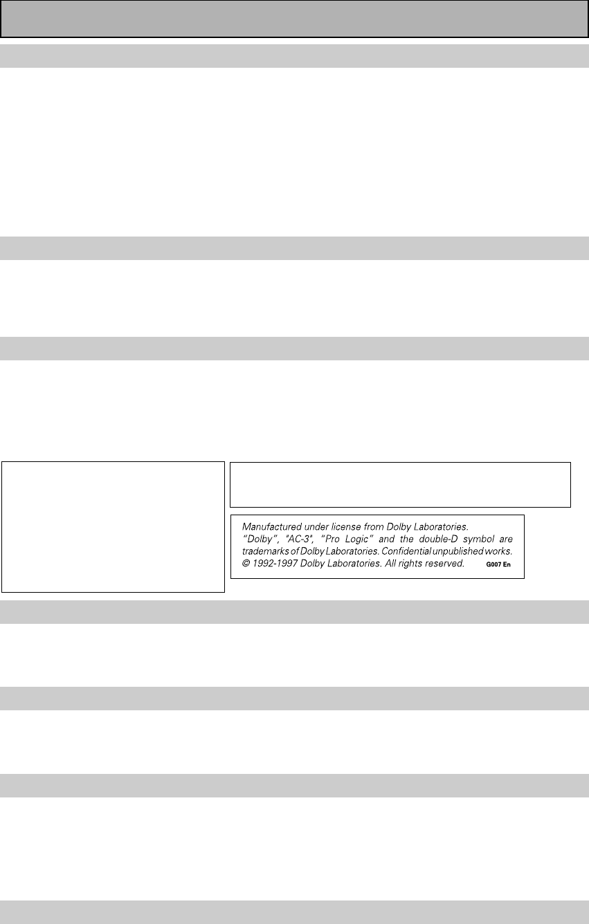
Checking the Supplied Accessories
Please check that you have received all of the following supplied accessories.
How to Use This Manual
Preparing the Remote Control
Loading the batteries
Load the batteries into the remote control as shown below. The remote control uses a lot of power due to the
LCD display so please use alkaline batteries. Depending on individual use you may have to change the batteries
fairly often but most users should be able to get an average of 1-3 months of battery life. When you notice a
decrease in the operating range or if the alarm sounds (see next page), replace all batteries with new ones.
NOTE: After replacing the batteries, the touch panel will need re-adjusting (see p.28-29).
ª
ª
ª
ª
· ·
·
·
12 3
\\
“AA” IEC LR6
batteries x 4 Remote control unit
Touch pen Cushion for
Remote x 4
(Attached to the back
of the remote control)
CAUTION!
Incorrect use of batteries may result in such hazards as leakage and bursting. Observe the following precautions.
• Never use new and old batteries together.
• Insert the plus and minus sides of the batteries properly according to the marks in the battery case.
• Batteries with the same shape may have different voltages. Do not use different batteries together.
• When disposing of used batteries, please comply with governmental regulations or environmental public institution’s
rules that apply in your country or area.
“AA” IEC LR6
batteries x 4
memo
Operating Instructions
10
En
Touch pen
Change Battery !!
OK ?
SIZE AA, LR6SIZE AA, LR6
lock switch
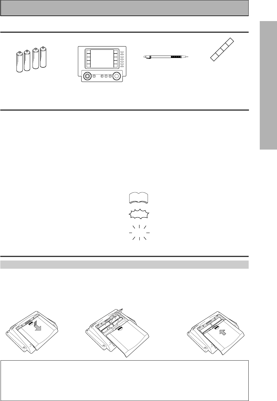
Remote Control Battery Alarm
When the batteries get too weak to operate the remote control properly an alarm
will sound and a warning screen will appear on the remote. Change the batteries as
shown on the previous page.
The Touch Pen & Lock
The touch pen is located in the back right-hand corner of the
remote control. Take it out by sliding your finger along the bottom
right edge of the remote control and then grasping the pen with
thumb and forefinger.
The lock switch is located in the top right-hand corner on the back
of the remote control. When this switch is set to LOCK you can’t
use the buttons on the remote control. This is helpful to prevent
you from mistakenly pushing a button. For normal use keep the
switch set in USE.
Remote Control Cushions
Apply the cushions to the feet of the remote control as shown in the
diagram right.
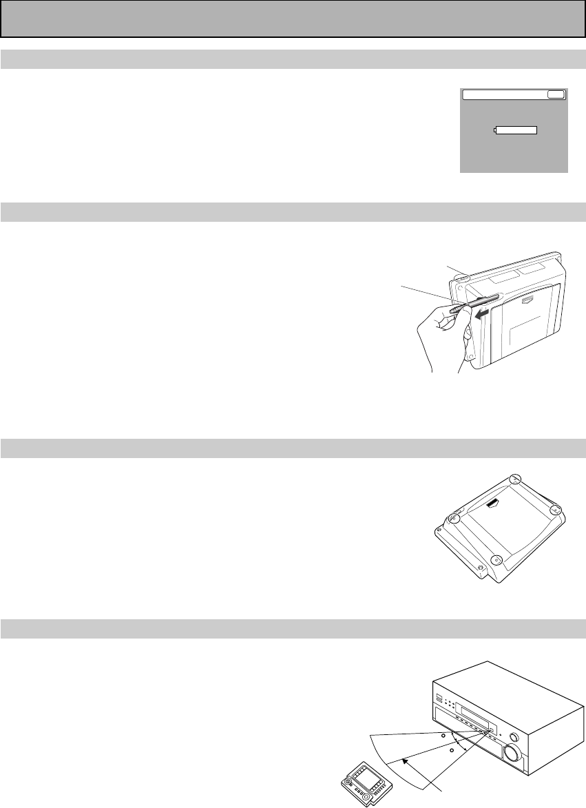
Operating range of remote control unit
The area in which you can use the remote control to operate the
VSA-E08 is fairly large. To use, point the remote control toward
the remote sensor on the front panel of this unit while within
the range shown right.
Remote control may not function properly if:
• There are obstacles between the remote control and the
remote sensor.
• Direct sunlight or fluorescent light is shining onto the
remote sensor.
• The amplifier located near a device emitting infrared rays.
• Operated simultaneously with another remote control which
uses infrared rays.
30
30
7m
Before You Start
11
PREPARATION
En
Installing the Amplifier
Ventilation
• When installing this unit, make sure to leave space around the unit for ventilation to improve heat radiation (at
least 60 cm at the top, 10 cm at the rear, and 30 cm at each side). If not enough space is provided between
the unit and walls or other equipment, heat will build up inside, interfering with performance or causing
malfunctions.
• Do not place on a thick carpet, bed, sofa or fabric having a thick pile. Do not cover with fabric or other
covering.
Anything that blocks ventilation will cause the internal temperature to rise, which may lead to breakdown or
fire hazard.
Opening the Front Panel
To open the front panel push gently on the lower third of the panel with your finger.
Before You Start
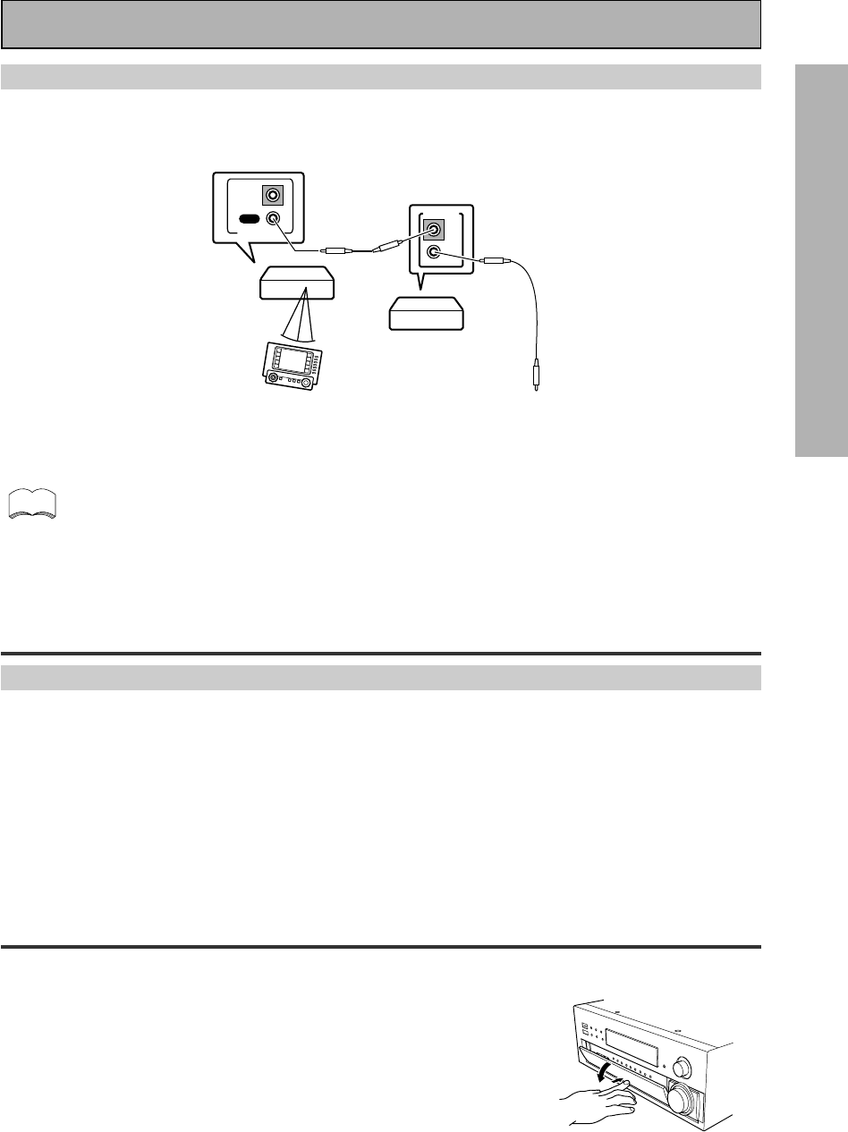
The PIONEER SR System: Operating other PIONEER components
Connecting an optional control cord allows you to operate other PIONEER components simply by pointing the
amplifier’s remote control at the remote sensor on the front panel of the amplifier. The amplifier then sends the
remote control signals to the other devices via the CONTROL OUT terminal.
• You can also control PIONEER components (and those made by other manufacturers) by pointing the
receiver's remote control directly at the respective component. This type of operation does not re-
quire control cords. All you have to do is recall the appropriate the stored settings (see p. 52).
• If you use a remote control hooked up via the CONTROL IN jack with a control cord, you won't be able
to use this unit's remote control.
IN
CONTROL
OUT
IN
CONTROL
OUT
PIONEER component
bearing the Î mark.
Remote Control To CONTROL IN
terminal of another
PIONEER component
bearing the Î mark.
Amplifier
memo
12
En
Connecting Your Equipment
Before making or changing the connections, switch off the power and
disconnect the power cord from the AC outlet.
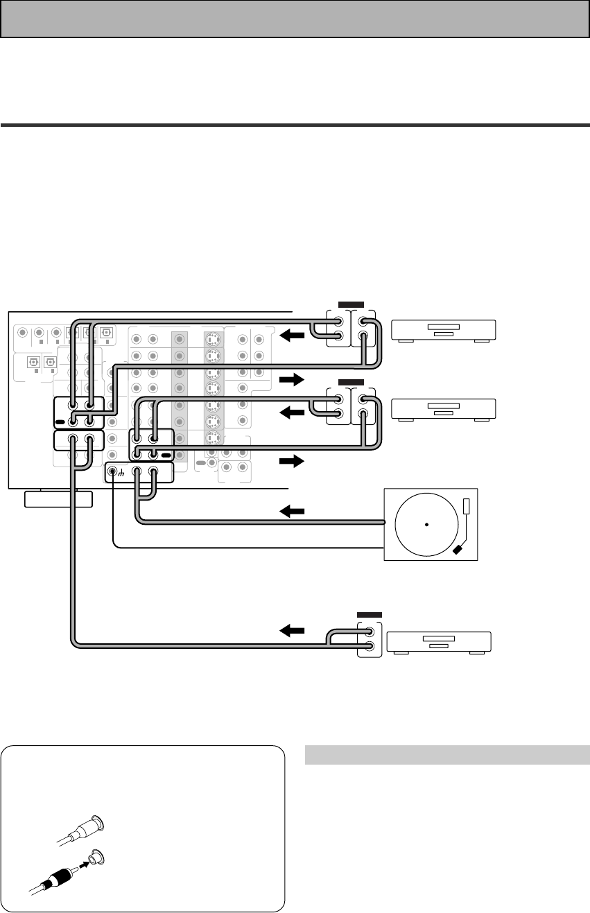
Audio Components
To begin set up connect your audio components to the jacks as shown below. These are all analog
connections and your analog audio components (turntable, cassette deck) use these jacks.
Remember that for components you want to record with you need to hook up four plugs (a set of
stereo ins and a set of stereo outs), but for components that only play (like a turntable) you only
need to hook up one set of stereo plugs (two plugs). To use DTS or Dolby Digital surround sound
features you must hook up your digital components to the digital inputs (see p.13). We also
recommend hooking up your digital components to analog audio jacks. If you want to record to/
from digital components (like an MD) to/from analog components you must hook up your digital
equipment with these analog connections. See p.13,14 for more on digital connections.
*The arrows indicate the direction of the audio signal.
If your turntable
has a ground
wire, connect it
to the SIGNAL
GND terminal.
7 Audio cords
Use audio cords (not supplied) to
connect the audio components.
Connect red plugs to
R (right) and white
plugs to L (left).
Be sure to insert
completely.
Cassette deck placement
Depending on where the cassette deck is
placed, noise may occur during playback of
your cassette deck which is caused by leakage
flux from the transformer in the amplifier. If you
experience noise, move the cassette deck
farther away from the amplifier.
L
R
CD
IN
RL
RL
MD /
TAPE1/
CD-R
PLAY
REC
TAPE2
MONITOR
PLAY
REC
IN
PHONO
MONITOR
OUT 2
MONITOR
OUT 1
SURR-
OUND
SUB
WOOFER
CENTER
FRONT
MULTI CH IN
SURR-
OUND
FRONT
SUB
WOOFER
PRE OUT
CENTER
RL
L
R
R
L
R
L
R
RL
L (Songle)
COMPONENT VIDEO
DVD/LD
IN TV/SAT
IN
Y
P
B
P
R
MONITOR
OUT
P
B
P
R
Y
MULTI CH IN
SURROUND
BACK
SURROUND
BACK
PRE OUT
DVD /
LD
IN
S VIDEOVIDEO VIDEOAUDIO
IN
TV /
SAT
IN
IN
OUT
IN
VCR1 /
DVR
OUT
IN
OUT
IN
VCR2
OUT
IN
CONTROL
IN
OUT
PCM /
2
/ DTS/ MPEG
DIGITAL
IN
5
IN
4
IN
3
2
RF IN
(AC-3) IN
2
IN
1
LINE/
TUNER
IN
AUDIO
OUTOUT
21
CD player
Turntable
OUTPUT
L
R
ANALOG
Recorder 1 (MD/Tape )
Recorder 2 (MD/Tape )
OUTPUT
(PLAY)
L
R
INPUT
(REC)
L
R
ANALOG
OUTPUT
(PLAY)
L
R
INPUT
(REC)
L
R
ANALOG
Please don't hook up any other component to the phono jacks other than a turntable. It could
damage the equipment. If your turntable has a built-in amplifier please hook it up to the LINE IN or
another input other than the PHONO.
13
PREPARATION
En
Connecting Your Equipment
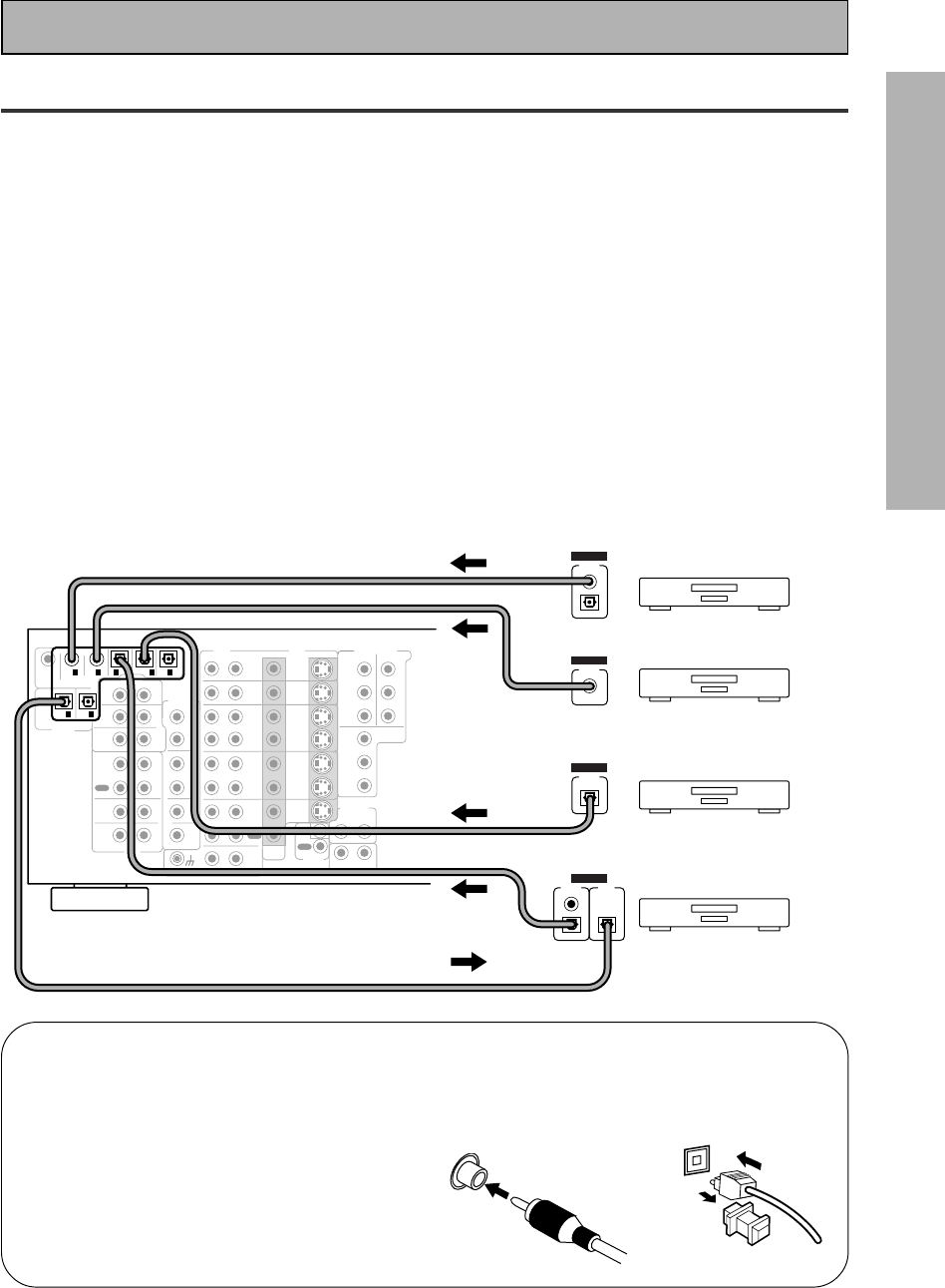
Digital Connections
In order to use Dolby Digital/DTS soundtracks which are at the heart of home theater you need to
make digital audio connections. You can do this by either a coaxial or an optical connection (you
don’t need to do both). The quality of these two types of connections is the same but since some
digital components only have one type of digital terminal, it is a matter of matching like with like
(for example, the coaxial out from the component to coaxial in on the amplifier). The VSA-E08 has
two coaxial and three optical inputs for a total of five digital inputs. A DVD/LD player or LD player
should be connected to a digital jack and the special 2 RF jack (if the LD has one) as well as a pair
of analog jacks (see the next page). If possible hook up your digital equipment in accordance with
this amplifier's default settings, see Digital Input Assignment, below left, in order to do this.We also
recommend hooking up your digital components to analog audio jacks in order to make recording
from some digital sources which may be copy protected.
Connect your digital components as shown below.
There are two optical digital out jacks (the MD recorder is connected to one in the diagram below).
If you connect this to the optical input on a digital recorder (currently these include MD, DAT and
CD-R) you can make direct digital recordings with this unit.
Before making or changing the connections, switch off the power and disconnect the power cord
from the AC outlet.
*The arrows indicate the direction of the audio signal.
7Coaxial cords/Optical cables
Commercially available digital audio
coaxial cords (standard video cords can
also be used) or optical cables (not
supplied) are used to connect digital
components to this amplifier.
When you use optical digital input or
output terminals, pull off the caps and
insert the plugs. Be sure to insert
completely.
Coaxial cord
(or standard
video cord)
Optical cable
CD
IN
RL
RL
MD /
TAPE1/
CD-R
PLAY
REC
TAPE2
MONITOR
PLAY
REC
IN
PHONO
MONITOR
OUT 2
MONITOR
OUT 1
SURR-
OUND
SUB
WOOFER
CENTER
FRONT
MULTI CH IN
SURR-
OUND
FRONT
SUB
WOOFER
PRE OUT
CENTER
RL
L
R
R
L
R
L
R
RL
L (Songle)
COMPONENT VIDEO
DVD/LD
IN TV/SAT
IN
Y
P
B
P
R
MONITOR
OUT
P
B
P
R
Y
MULTI CH IN
SURROUND
BACK
SURROUND
BACK
PRE OUT
DVD /
LD
IN
S VIDEOVIDEO VIDEOAUDIO
IN
TV /
SAT
IN
IN
OUT
IN
VCR1 /
DVR
OUT
IN
OUT
IN
VCR2
OUT
IN
CONTROL
IN
OUT
PCM /
2
/ DTS/ MPEG
DIGITAL
IN
5
IN
4
IN
3
2
RF IN
(AC-3) IN
2
IN
1
LINE/
TUNER
IN
AUDIO
OUTOUT
21
MD recorder
OUTPUT
(PLAY) INPUT
(REC)
DIGITAL
TV tuner
DVD player
OUTPUT
DIGITAL
OUTPUT
DIGITAL
CD player
OUTPUT
DIGITAL
(not a PCM-only output)
14
En
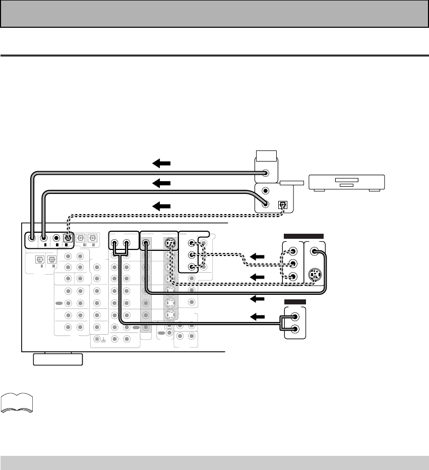
Connecting Your Equipment
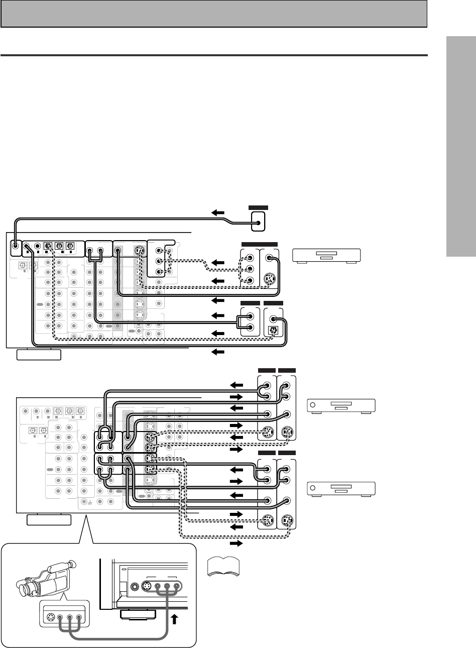
Example Connection for a DVD/LD or LD player
Make sure you connect your DVD/LD or LD players using both the 2 RF jack and either a coaxial or
optical (you don't need to do both of these) digital connections. If your player has an 2 RF output
this will ensure you can use all LDs (see p.15).
We also recommend hooking up your digital components to analog audio jacks.
Before making or changing the connections, switch off the power and disconnect the power cord
from the AC outlet.
*The arrows indicate the direction of the video signal.
memo
CD
IN
RL
RL
MD /
TAPE1/
CD-R
PLAY
REC
TAPE2
MONITOR
PLAY
REC
IN
PHONO
MONITOR
OUT 2
MONITOR
OUT 1
SURR-
OUND
SUB
WOOFER
CENTER
FRONT
MULTI CH IN
SURR-
OUND
FRONT
SUB
WOOFER
PRE OUT
CENTER
RL
L
R
R
L
R
L
R
RL
L
(Songle)
COMPONENT VIDEO
DVD/LD
IN TV/SAT
IN
Y
P
B
P
R
MONITOR
OUT
P
B
P
R
Y
MULTI CH IN
SURROUND
BACK
SURROUND
BACK
PRE OUT
DVD /
LD
IN
S VIDEOVIDEO VIDEOAUDIO
IN
TV /
SAT
IN
IN
OUT
IN
VCR1 /
DVR
OUT
IN
OUT
IN
VCR2
OUT
IN
CONTROL
IN
OUT
PCM /
2
/ DTS/ MPEG
DIGITAL
IN
5
IN
4
IN
3
2
RF IN
(AC-3) IN
2
IN
1
LINE/
TUNER
IN
AUDIO
OUTOUT
21
DVD/LD player
or LD player
1
23
DIGITAL OUT
(AC-3)(LD)
RF OUT
2
COMPO-
NENT VIDEO
OUT
VIDEO
S-VIDEO
P
B
Y
P
R
STEREO
L
R
ANALOG
Digital Input Assignment
Unlike analog connections, the jacks for digital connections are not dedicated to one type of
component, they can be used freely. Thus you must tell the amplifier what digital component in
which jack so your components will be in sync with the names on the remote control buttons and
the like. To avoid having to assign the digital inputs you can hook up your equipment in accordance
with the amplifier's default settings.
The default are:
DIGITAL IN 1: DVD/LD
DIGITAL IN 2: CD
DIGITAL IN 3: MD
DIGITAL IN 4: TV/SAT
DIGITAL IN 5 VCR1
AC-3 RF: DVD/LD
You will notice that Digital IN 1, for example, is a coaxial jack. If your DVD/LD player only has an
optical out jack on it then you won't be able to hook up your components in accordance with the
VSA-E08's default setting. In this case you will need to assign the digital inputs. See DIGITAL INPUT
SELECT on p.31 in order to do this.
Be sure to make either a digital coaxial or digital optical connection (pictured as DIGITAL
jack 1 or DIGITAL jack 3 in this diagram) as well, but you DON'T need to make both.
Also, be sure to assign the jacks to the proper component(s) with the DIGITAL INPUT
SELECT procedure (see p.31) if necessary. See the explanation on the left for details.
(not a PCM-only output)
15
PREPARATION
En
Connecting Your Equipment
Video Components
Connect your video components to the jacks as shown below. Regarding a DVD there are two types
of connections to make. Hook up your video signal with either component video, S-video, or
composite video cords (the quality descends in this order) but remember, the video component you
are watching and your TV must be hooked up with same type of video cord or you won't be able to
see the picture. For the audio signal, order to use Dolby Digital/DTS you must hook up a digital
input. It is also a good idea to hook up your DVD components with analog audio connections as
well, since some DVDs may not have a digital audio track. To cover all possible laser discs a DVD/LD
player or LD player requires an analog connection and two digital connections (a coaxial or optical
and a specialized 2 RF connection shown at the very top of the first diagram below).
Before making or changing the connections, switch off the power and disconnect the power cord
from the AC outlet.
*The arrows indicate the direction of the video signal.
RL
CD
IN
RL
MD /
TAPE1/
CD-R
PLAY
REC
TAPE2
MONITOR
PLAY
REC
IN
PHONO
MONITOR
OUT 2
MONITOR
OUT 1
SURR-
OUND
SUB
WOOFER
CENTER
FRONT
MULTI CH IN
SURR-
OUND
FRONT
SUB
WOOFER
PRE OUT
CENTER
RL
L
R
R
L
R
L
R
RL
L (Songle)
COMPONENT VIDEO
DVD/LD
IN TV/SAT
IN
Y
P
B
P
R
MONITOR
OUT
P
B
P
R
Y
MULTI CH IN
SURROUND
BACK
SURROUND
BACK
PRE OUT
DVD /
LD
IN
S VIDEOVIDEO VIDEOAUDIO
IN
TV /
SAT
IN
IN
OUT
IN
VCR1 /
DVR
OUT
IN
OUT
IN
VCR2
OUT
IN
CONTROL
IN
OUT
PCM /
2
/ DTS/ MPEG
DIGITAL
IN
5
IN
4
IN
3
2
RF IN
(AC-3) IN
2
IN
1
LINE/
TUNER
IN
AUDIO
OUTOUT
21 DVD/LD player
COMPO-
NENT VIDEO
OUT
L
VIDEO
STEREO
L
R
DIGITAL
ANALOG
PCM/
2
/ DTS
DIGITAL
S-VIDEO
Y
P
B
P
R
2 RF
OUT
CD
IN
RL
RL
MD /
TAPE1/
CD-R
PLAY
REC
TAPE2
MONITOR
PLAY
REC
IN
PHONO
MONITOR
OUT 2
MONITOR
OUT 1
SURR-
OUND
SUB
WOOFER
CENTER
FRONT
MULTI CH IN
SURR-
OUND
FRONT
SUB
WOOFER
PRE OUT
CENTER
RL
L
R
R
L
R
L
R
RL
L (Songle)
COMPONENT VIDEO
DVD/LD
IN TV/SAT
IN
Y
P
B
P
R
MONITOR
OUT
P
B
P
R
Y
MULTI CH IN
SURROUND
BACK
SURROUND
BACK
PRE OUT
DVD /
LD
IN
S VIDEOVIDEO VIDEOAUDIO
IN
TV /
SAT
IN
IN
OUT
IN
VCR1 /
DVR
OUT
IN
OUT
IN
VCR2
OUT
IN
CONTROL
IN
OUT
PCM /
2
/ DTS/ MPEG
DIGITAL
IN
5
IN
4
IN
3
2
RF IN
(AC-3) IN
2
IN
1
LINE/
TUNER
IN
AUDIO
OUTOUT
21
VCR 1/DVR
VCR 2
VIDEO
S-VIDEO
VIDEO
S-VIDEO
AUDIO
(PLAY)
L
R
AUDIO
(REC)
L
R
S-VIDEO
VIDEOVIDEO
S-VIDEO
AUDIO
(PLAY)
L
R
AUDIO
(REC)
L
R
OUT IN
OUT IN
PHONES S-VIDEO VIDEO L AUDIO R
VIDEO INPUT
LV R
VIDEO INPUT
Connecting DVD/LD players
Connecting VCRs or DVRs
If your video components have S-video jacks, you
could use S-video cords (not supplied) to connect
them on the back of the amplifier. These jacks are
labeled by the Japanese designation "S" on the
VSA-E08 but they are simply S-video jacks.
However, if you use S-video cords for your video
hook ups you must also hook up your TV with S-
video connections. Conversely, if you use regular
composite video cords for video hook ups, you
should use them for your TV as well.
7 Front
Front video connections are accessed via the
front panel input selector as "VIDEO."
memo
If you hook up your DVD/LD
player using component video
connections be sure to select
component video output on
your DVD player as well. See
you DVD manual for details.
LD player only
(not a PCM-only output)
16
En
Connecting Your Equipment
CD
IN
RL
RL
MD /
TAPE1/
CD-R
PLAY
REC
TAPE2
MONITOR
PLAY
REC
IN
PHONO
MONITOR
OUT 2
MONITOR
OUT 1
SURR-
OUND
SUB
WOOFER
CENTER
FRONT
MULTI CH IN
SURR-
OUND
FRONT
SUB. W
PRE OUT
CENTER
RL
L
R
R
L
R
L
R
RL
L
(Songle)
COMPONENT VIDEO
DVD/LD
IN TV/SAT
IN
Y
P
B
P
R
MONITOR
OUT
P
B
P
R
Y
MULTI CH IN
SURROUND
BACK
SURROUND
BACK
PRE OUT
DVD /
LD
IN
S VIDEOVIDEO VIDEOAUDIO
IN
TV /
SAT
IN
IN
OUT
IN
VCR1 /
DVR
OUT
IN
OUT
IN
VCR2
OUT
IN
CONTROL
IN
OUT
PCM /
2
/ DTS/ MPEG
DIGITAL
IN
5
IN
4
IN
3
2
RF IN
(AC-3) IN
2
IN
1
LINE/
TUNER
IN
AUDIO
OUTOUT
21
TV/Satellite tuner
COMPO-
NENT VIDEO
OUT
VIDEO
STEREO
L
R
DIGITAL
ANALOG
DIGITAL
S-VIDEO
Y
P
B
P
R
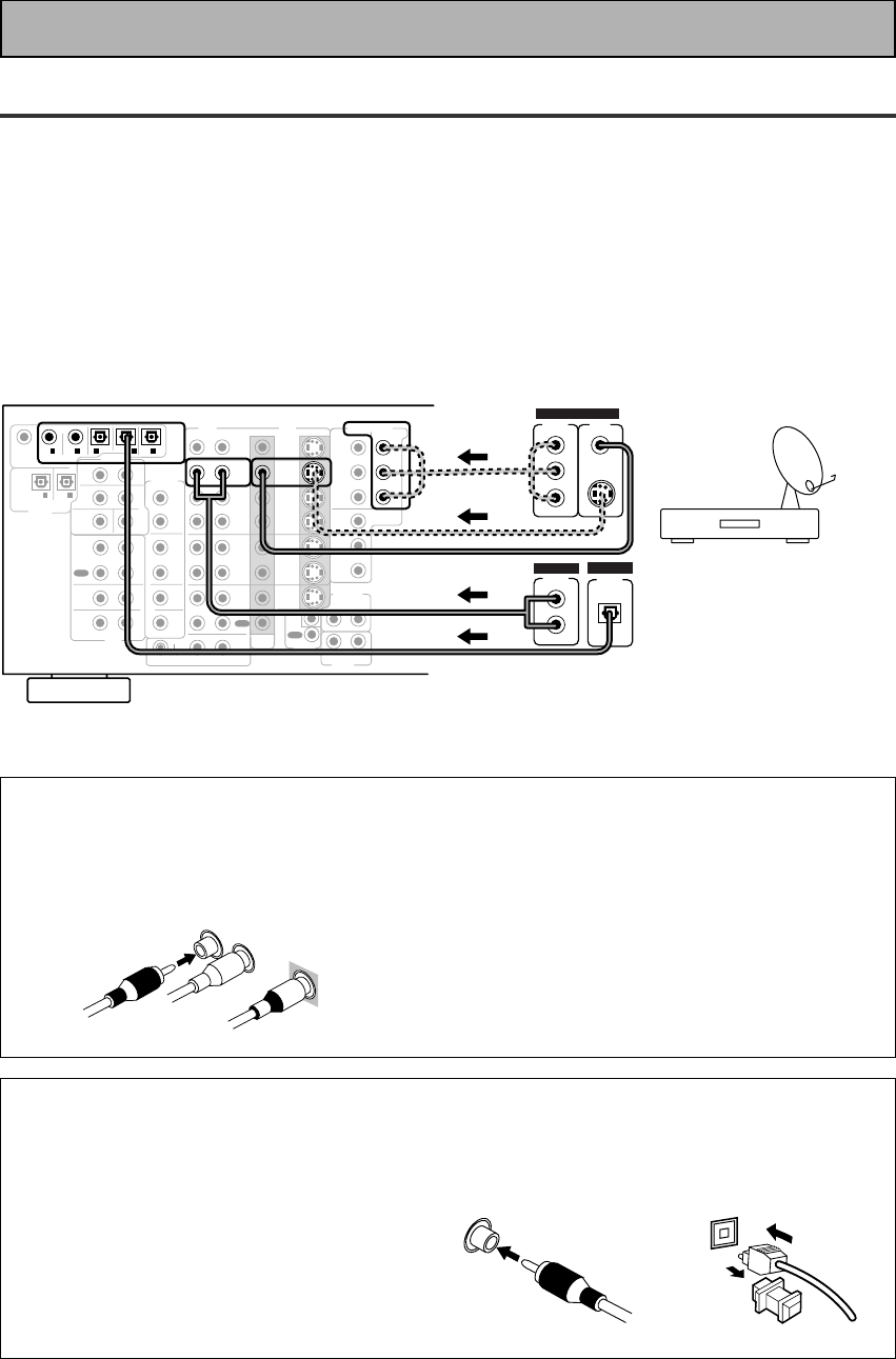
Satellite TV Components
Connect your satellite TV components to the jacks as shown below. Hook up the video signal with
either component video, S-video, or composite video cords (the quality descends in this order) but
remember, the video component you are watching and your TV must be hooked up with same type
of video cord or you won't be able to see the picture. For the audio signal, order to use digital
soundtracks (sometimes broadcast over digital satellite TV) you must hook up a digital input. Use
either a coaxial or optical cables, it doesn't matter which (you don't need to use both). It's also a
good idea to hook up your audio with analog cables (see below). This connection is called STEREO
AUDIO OUT in the diagram.
Before making or changing the connections, switch off the power and disconnect the power cord
from the AC outlet.
*The arrows indicate the direction of the TV signal.
7Digital audio coaxial cords/
Optical cables
Commercially available digital audio
coaxial cords (standard video cords can
also be used) or optical cables (not
supplied) are used to connect digital
components to this amplifier.
When you use optical digital input or
output terminals, pull off the caps and
insert the plugs. Be sure to insert
completely.
Digital audio
coaxial cord
(or standard
video cord)
Optical cable
7 Analog audio/video cords
Use audio/video cords (not supplied) to
connect the video components and a video
cord to connect the monitor TV.
Connect red plugs to R (right), white plugs
to L (left), and the yellow plugs to VIDEO.
Be sure to insert completely.
L
R
VIDEO
17
PREPARATION
En
Connecting Your Equipment
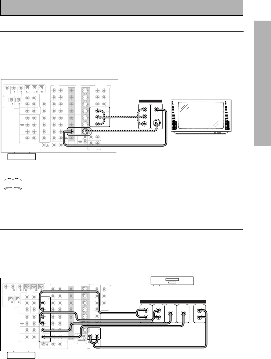
TV
Connect your TV to the jacks as shown below. Hook up the signal with either component video, S-
video, or composite video cords (the quality descends in this order) but remember, the video
component you are watching and your TV must be hooked up with same type of video cord or you
won't be able to see the picture.
Before making or changing the connections, switch off the power and disconnect the power cord
from the AC outlet.
CD
IN
RL
RL
MD /
TAPE1/
CD-R
PLAY
REC
TAPE2
MONITOR
PLAY
REC
IN
PHONO
MONITOR
OUT 2
MONITOR
OUT 1
SURR-
OUND
SUB
WOOFER
CENTER
FRONT
MULTI CH IN
SURR-
OUND
FRONT
SUB
WOOFER
PRE OUT
CENTER
RL
L
R
R
L
R
L
R
RL
L
(Songle)
COMPONENT VIDEO
DVD/LD
IN TV/SAT
IN
Y
P
B
P
R
MONITOR
OUT
P
B
P
R
Y
MULTI CH IN
SURROUND
BACK
SURROUND
BACK
PRE OUT
DVD /
LD
IN
S VIDEOVIDEO VIDEOAUDIO
IN
TV /
SAT
IN
IN
OUT
IN
VCR1 /
DVR
OUT
IN
OUT
IN
VCR2
OUT
IN
CONTROL
IN
OUT
PCM /
2
/ DTS/ MPEG
DIGITAL
IN
5
IN
4
IN
3
2
RF IN
(AC-3) IN
2
IN
1
LINE/
TUNER
IN
AUDIO
OUTOUT
21
TV/monitor
COMPO-
NENT VIDEO
VIDEO IN
S-VIDEO
Y
PB
PR
Multi Channel Input (External Decoder)
In some cases you may want to have your source material (DVD, etc.) decoded externally. If you
find you need a multi channel external decoder hook one up as shown below, but for most people
this component is unnecessary (for more on this see p.50).
Before making or changing the connections,switch off the power and disconnect the power cord
from the AC outlet.
CD
IN
RL
RL
MD /
TAPE1/
CD-R
PLAY
REC
TAPE2
MONITOR
PLAY
REC
IN
PHONO
MONITOR
OUT 2
MONITOR
OUT 1
SURR-
OUND
SUB
WOOFER
CENTER
FRONT
MULTI CH IN
SURR-
OUND
FRONT
SUB
WOOFER
PRE OUT
CENTER
RL
L
R
R
L
R
L
R
RL
L
(Songle)
COMPONENT VIDEO
DVD/LD
IN TV/SAT
IN
Y
P
B
P
R
MONITOR
OUT
P
B
P
R
Y
MULTI CH IN
SURROUND
BACK
SURROUND
BACK
PRE OUT
DVD /
LD
IN
S VIDEOVIDEO VIDEOAUDIO
IN
TV /
SAT
IN
IN
OUT
IN
VCR1 /
DVR
OUT
IN
OUT
IN
VCR2
OUT
IN
CONTROL
IN
OUT
PCM /
2
/ DTS/ MPEG
DIGITAL
IN
5
IN
4
IN
3
2
RF IN
(AC-3) IN
2
IN
1
LINE/
TUNER
IN
AUDIO
OUTOUT
21
Components equipped with
7.1 (5.1) channel analog output jack
SUB
WOOFER SURR-
OUND BACK
L
R
CENTER
SURR-
OUND
L
R
FRONT
L
R
ANALOG
memo The COMPONENT VIDEO OUT jack can be used to get a TV picture but it doesn't show
this receiver's on screen display (OSD).
If you use S video cords to hook up a component the OSDs from the receiver will only be
able to be seen on the S video out terminals.
18
En
MONITOR
OUT 2
MONITOR
OUT 1
CD
IN
SURR-
OUND
SUB
WOOFER
CENTER
FRONT
MULTI CH IN
SURR-
OUND
FRONT
SUB
WOOFER
PRE OUT
CENTER
RL
L
R
R
L
R
R
L
L
RL
R
RL
L
(Songle)
COMPONENT VIDEO
DVD/LD
IN TV/SAT
IN
Y
P
B
P
R
MONITOR
OUT
P
B
P
R
Y
MULTI CH IN
SURROUND
BACK
SURROUND
BACK
PRE OUT
DVD /
LD
IN
S VIDEOVIDEO VIDEOAUDIO
IN
TV /
SAT
IN
IN
OUT
IN
VCR1 /
DVR
OUT
IN
OUT
IN
VCR2
OUT
IN
CONTROL
IN
OUT
MD /
TAPE1/
CD-R
PLAY
REC
TAPE2
MONITOR
PLAY
REC
PCM /
2
/ DTS/ MPEG
DIGITAL
IN
5
IN
4
IN
3
2
RF IN
(AC-3) IN
2
IN
1
IN
PHONO
LINE/
TUNER
IN
AUDIO
OUTOUT
21
SPEAKERS
A
FRONT CENTER
SURROUND
FRONT
B
SWITCHED
TOTAL 100W MAX UNSWITCHED
100W MAX
AC OUTLETS
RLRLRL
Surround
speaker
(Right)
Surround back
speaker (Right)
Surround back
speaker (Left)
INPUT
Powered
sub-woofer
Additional Amplifier (See p.20)
Surround
speaker
(Left)
Front
speaker (A)
(Left)
Front
speaker (A)
(Right)
TV/monitor
Center
speaker
memo
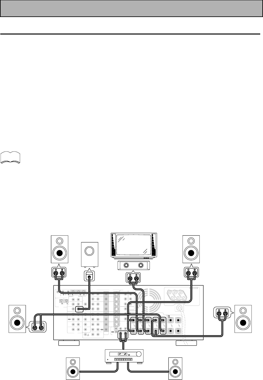
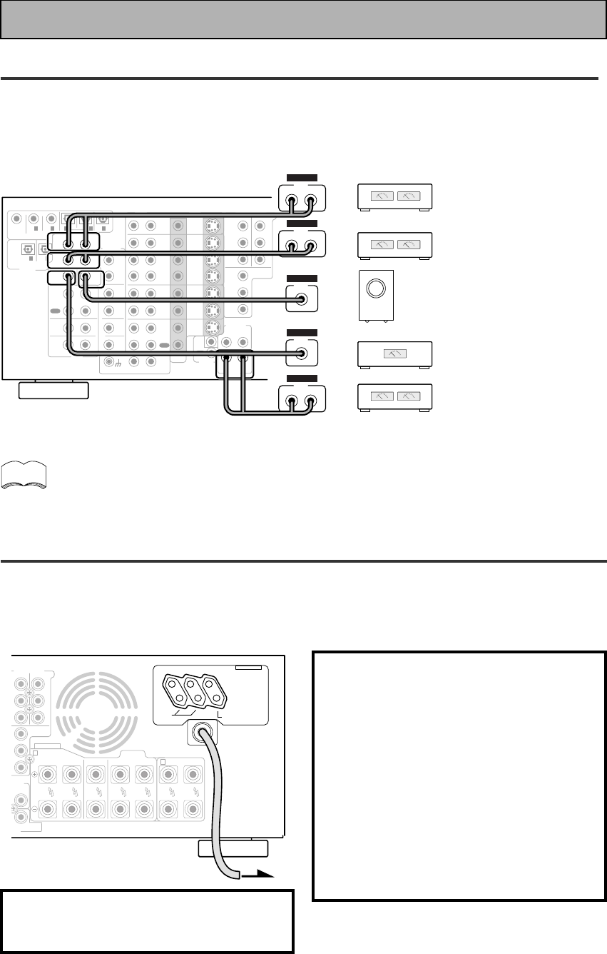
Connecting Your Equipment
Speakers
A full complement of eight speakers is shown here but, naturally, everyone's home set up will
vary. Simply connect the speakers you have in the manner described below. The VSA-E08 will
work with just two stereo speakers (called "front" speakers in the diagram) but the amplifier is
designed to be used with at least three speakers.
One of the latest features of home theater is the use of SURROUND BACK speakers. These
speakers add even great realism in movie sound effects and new discs with soundtracks in Dolby
Digital or DTS incorporates these channels. In order to be able to use these channels you must
hook your SURROUND BACK speakers up to an external amplifier and then connect that to the
VSA-E08, as shown in the diagram below. If you only have one SURROUND BACK speaker hook it
up the SURROUND BACK L (SINGLE) terminal on the back of the amplifier.
In general, make sure you connect the speaker on the right to the right terminal and the speaker on
the left to the left terminal. Also make sure the positive and negative (+/–) terminals on the
amplifier match those on the speakers. Before making or changing the connections, switch off the
power and disconnect the power cord from the AC outlet.
The VSA-E08 has two speaker systems, A & B. A is the main system supporting the full
complement of surround sound speakers. If you switch on both A & B speaker systems,
only front speakers and the subwoofer will be audible. No sound will come from the
center or surround speakers but multi channel sources will be down-mixed to the active
speakers so no sound will be lost. Similarly, if you choose just the B system you‘ll only
hear the front speakers connected to the B system and multi channel sources will be
down-mixed to these two speakers.
Please use speakers with a nominal impedance rated 6Ω-16Ω.
For instructions explaining the speaker terminals see the next page.
The illustration is not applicable to the UK model.
19
PREPARATION
En
Connecting Your Equipment
Placing Your Speakers
Proper speaker placement is essential to realize the best sound from your system. The diagram and
tips given here are just a rough guide; be sure to read the instructions that come with your
speakers.
Speaker placement
If you have a multiple speaker arrangement the placement of the speakers is extremely important.
To achieve the best possible surround sound, install your speakers as shown below. Make sure all
speakers are installed securely to prevent accidents and improve sound quality. Be sure to consult
your speaker manuals for the best placement of the speakers. Some speakers are designed to be
floor-standing but others benefit greatly from speakers stands which raise them off the floor.
• Install the left and right front speakers at equal distances from the TV.
• When installing speakers near the TV, we recommend using magnetically shielded
speakers to prevent possible interference such as distortion in the color of the TV
screen. If you do not have magnetically shielded speakers and notice discoloration of
the TV screen, place the speakers farther away from the TV.
• Install the center speaker above or below the TV so that the sound of the center
channel is localized at the TV screen.
CAUTION:
When installing the center speaker on top of the TV, be sure to secure it with tape or
some other suitable means. Otherwise, the speaker may fall from the TV due to external
shocks such as earthquakes, and it may lead to endangering those nearby or damaging
the speaker.
• If possible, install the surround speakers slightly above ear level.
• It may be difficult to obtain a cohesive surround effect if the surround speakers are
installed farther away from the listening position than the front and center speakers.
memo
7 Speaker terminals
11
11
1Twist exposed wire
strands together.
22
22
2Loosen speaker terminal
and insert exposed wire.
33
33
3Tighten
terminal.
10mm
Surround
Left
Surround Back
Left
Surround
Right
Surround Back
Right
Listening
Position
Front
Left
Front
RightCenter
Sub
Woofer
20
En
Connecting Your Equipment
Connecting additional amplifiers
To hook up surround back speakers you need to use an additional amplifier. Other than for that
purpose this amplifier has more than sufficient power for any home use, but it is possible to add
additional amplifiers to every channel of your system. Make the connections shown below to add
amplifiers to power your speakers.
Before making or changing the connections, switch off the power and disconnect the power cord
from the AC outlet.
CD
IN
RL
RL
MD /
TAPE1/
CD-R
PLAY
REC
TAPE2
MONITOR
PLAY
REC
IN
PHONO
MONITOR
OUT 2
MONITOR
OUT 1
SURR-
OUND
SUB
WOOFER
CENTER
FRONT
MULTI CH IN
SURR-
OUND
FRONT
SUB
WOOFER
PRE OUT
CENTER
RL
L
R
R
L
R
L
R
RL
L
(Songle)
COMPONENT VIDEO
DVD/LD
IN TV/SAT
IN
Y
P
B
P
R
MONITOR
OUT
P
B
P
R
Y
MULTI CH IN
SURROUND
BACK
SURROUND
BACK
PRE OUT
DVD /
LD
IN
S VIDEOVIDEO VIDEOAUDIO
IN
TV /
SAT
IN
IN
OUT
IN
VCR1 /
DVR
OUT
IN
OUT
IN
VCR2
OUT
IN
CONTROL
IN
OUT
PCM /
2
/ DTS/ MPEG
DIGITAL
IN
5
IN
4
IN
3
2
RF IN
(AC-3) IN
2
IN
1
LINE/
TUNER
IN
AUDIO
OUTOUT
21
Surround channel amplifier
Front channel amplifier
Center channel amplifier
(mono)
Surround back channel
amplifier
Powered sub woofer
INPUT
LR
ANALOG
INPUT
LR
ANALOG
INPUT
LR
ANALOG
INPUT
ANALOG
INPUT
ANALOG
Plugging In (Except for the UK model)
Up to three components can be powered from this amplifier. Two of the outlets are switched, which
means that power is switched on and off with the amplifier. The third is unswitched, which means
that power is delivered so long as the amplifier is plugged in.
Before making or changing the connections,switch off the power and disconnect the power cord
from the AC outlet.
COMPONENT VIDEO
D
/LD
T
TV/SAT
IN
MONITOR
OUT
L
L (Single)
T
I CH IN
R
OUND
A
CK
R
OUND
A
CK
E
OUT
SPEAKERS
A
FRONT CENTER
SURROUND
FRONT
B
SWITCHED
TOTAL 100W MAX UNSWITCHED
100W MAX
AC OUTLETS
RLRLRL
Caution!
Power consumption of any equipment con-
nected to the switched power outlets should
not exceed 100 W (0.8A).
Power consumption of any equipment con-
nected to the unswitched power outlet should
not exceed 100 W (0.8A).
To avoid overheating, fire risk and possible
malfunction, do not connect high-wattage
appliances such as heaters, irons, monitors or
TV sets to this units AC outlets.
Disconnect the amplifier from the power outlet
when it's not in regular use, for example,
when on vacation.
memo You can use the additional amplifier on the surround back channels for a single speaker
as well. In this case plug the amplifier into the L (SINGLE) terminal only.
We suggest using a Pioneer M-10X or A-509R amplifier as your additional amp.
Caution !
Do not connect a monitor or TV to this unit's AC
OUTLETS.
21
PREPARATION
En
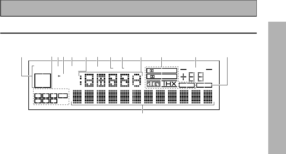
Display
All the display information is explained and/or referenced here.
Displays & Controls
DIGITAL
dB
PRO LOGIC
STEREO
DSP
MIDNIGHTLOUDNESSATTSIGNAL
SELECT OVER H.P
AC-3DTS MPEG
ANALOG
SP AB
LCRLFE
LS S RS
DIGITAL
AC-3RF
AUTO
MPEG TAPE 2
VOLUME
2
14
356789 10 11 12 13
14
5 LOUDNESS indicator (See p.49)
Lights when the LOUDNESS mode is on.
6 H.P (headphones)
Lights when headphones are connected to the
PHONES jack (speakers systems A and B both
turn off automatically).
7 MIDNIGHT indicator (See p.48)
Lights when the MIDNIGHT LISTENING mode
is on.
8 DSP indicator (See p.43-45)
Light when a DSP or Advanced Theater modes
are selected.
9 STEREO indicator
Lights when a STEREO mode is selected.
10 Function indicator
Displays the function.
11 2/dts/MPEG mode indicators
2 DIGITAL : When the 2/dts mode on the
amplifier is on, this indicator lights to indicate
playback of a Dolby Digital signal. However, 2
PRO LOGIC lights during 2 channel playback of
Dolby Digital.
2 PRO LOGIC : When the 2/dts mode on the
amplifier is on, this indicator lights during 2
channel playback. ( Both B or A+B speaker
systems turn off automatically when headphones
are plugged.)
DTS : Lights when DTS signals are input.
THX: Lights when the HOME THX CINEMA mode
is selected.
MPEG: Lights when MPEG signals are input.
12
MASTER VOLUME indication
Displays current volume level.
13
TAPE 2 indicator
Lights when the TAPE 2 monitor is on.
14
Character display
Displays sound modes, general information,
1 SIGNAL SELECT indicators
Light to indicate the input signal you selected
of the source signal.
ANALOG : Lights when analog signals are
assigned.
DIGITAL : Lights when digital audio signals are
selected.
AC-3 RF : Lights when AC-3 RF signals are
assigned.
AUTO : Lights when the receiver is set to select
the input signal automatically.
2 Program Format indicators
AC-3 : Lights when a source with Dolby Digital
signals is played.
DTS : Lights when a source with DTS audio
signals is played.
MPEG: Blinks when the MPEG mode is selected,
and lights when a source with MPEG audio signals
is played.
For Dolby Digital or DTS sources, these
indicators change according to which channels
are active in the source. When all three LS (left
surround), S (surround) and RS (right surround)
light at the same time it means a Source with
Surround EX or DTS-ES flag is being used.
L – Left front channel.
C – Center channel.
R – Right front channel.
LS – Left surround channel.
S – Surround channel (mono).
RS – Right surround channel.
LFE – Low Frequency Effects channel.
3 Analog level indicators
OVER – When the source signal is analog, this
lights if the signal is in danger of distorting.
Press INPUT ATT on the remote control to
lower the signal level.
ATT – Lights when INPUT ATT is used to
reduce the level of the analog source signal.
4 Speaker indicators
Light to indicate the current speaker system, A
and/or B.
22
En
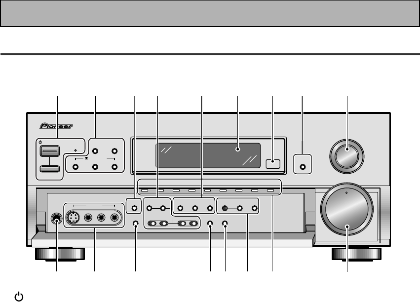
Displays & Controls
Front Panel
All the controls on the front panel are explained and/or referenced here. To open the front panel push
gently on the lower third of the panel.
STANDBY/ON DSP
MODE
INPUT
SELECTOR
MASTER
VOLUME
MIN MAX
THX CINEMA ADVANCED STANDARD
STANDBY
AUDIO/VIDEO MULTI-CHANNEL AMPLIFIER
STEREO/
DIRECT
/DTS/MPEG
N∫z¿x?˘
— OFF _ ON
PHONES
S-VIDEO VIDEO
MULTI CH
INPUT
SIGNAL
SELECT
EFFECT/
CH SELECT
FL
DIMMER
TAPE 2
MONITOR
VIDEO
SELECT
TONE
VIDEO VCR 1/DVR VCR 2 DVD/LD TV/SAT
MD/TAPE1/
CD-R
LINE/
TUNER
CD PHONO
CHANNEL
SELECT LOUDNESS
5-CHANNEL EQUAL POWER OUTPUT
DIGITAL
NR
-
+
SPEAKERS
-
TREBLE +
-
BASS +
L AUDIO R
VIDEO INPUT
12 536789
10 11 12 13 14 15 1716
4
1 STANDBY/ON button
Press to switch the amplifier ON or into
STANDBY mode.
STANDBY indicator
Lights when the amplifier is in STANDBY
mode. (Please note that this amplifier con-
sumes a small amount of power [1.0 W] in the
standby mode.)
_ ON/ — OFF button
If the button is OFF (—), the power of the
amplifier is shut off and the STANDBY/ON
button on the amplifier or the remote control do
not function. Pressing the button again will
turn the amplifier ON (_) and the amplifier
enters the standby mode. In the standby mode,
you can turn on the amplifier using the STAND-
BY/ON button on the amplifier or the remote
control.
2 DSP MODE button (See p.43)
Press repeatedly to select a DSP sound mode.
(HALL 1, HALL 2, JAZZ, DANCE, THEATER 1,
or THEATER 2, 5/7 CH STEREO). Use these
modes to produce surround sound from
standard (two channel) stereo sources and
create different listening environments.
STEREO/DIRECT button (See p.43,46,51)
Switches the amplifier into STEREO mode if it
was in a different sound mode (like DSP
MODE) or toggles between DIRECT and
STEREO mode. For more on STEREO mode
see p.43.
DIRECT playback bypasses the tone controls,
DIGITAL NR, LOUDNESS, MIDNIGHT and
channel level for the most accurate reproduc-
tion of a program source.
2/ DTS/ MPEG buttons (See p.41-45, 73-
74)
THX CINEMA – Cycles through the THX
CINEMA, THX SURRROUND EX or THX AUTO
sound modes. If you have THX-certified
speaker setup or want to re-create a THX-style
sound environment. It is also appropriate for
Dolby Digital, Dolby Pro Logic, DTS or MPEG
sources. Those with surround back speakers
can use all three THX modes, those without
can only use the THX CINEMA mode.
ADVANCED – Use to select one of the four
Advanced Theater modes. Use to create certain
types of sound environments when listening to
Dolby Digital, Dolby Pro Logic, DTS or MPEG
sources.
STANDARD – Use for pure decoding of multi
channel sources, especially Dolby Digital, Dolby
Pro Logic, DTS or MPEG sources. Each press
toggles between STANDARD and STANDARD
7.1 mode (for use with SURROUND BACK
speakers) and STANDARD auto (the amplifier
chooses the appropriate STANDARD mode).
Those with surround back speakers can use all
three STANDARD modes, those without can
only use the STANDARD mode.
3 MULTI CH INPUT (See p.50)
Use to hook up an external component that can
decode other types of signals and input them
into the VSA-E08.

23
PREPARATION
En
Displays & Controls
4 TONE control buttons
TONE button
This button has two functions. Firstly, it
switches between TONE ON and TONE
BYPASS, which bypasses the tone circuitry.
Secondly, you need to press the button before
using the CHANNEL SELECT buttons to adjust
the BASS & TREBLE (cannot be used in THX or
MULTI CH IN modes).
CHANNEL SELECT button
Switches the tone adjust controls between the
FRONT, CENTER, SURROUND and SUR-
ROUND BACK speakers. You can then use the
BASS and TREBLE controls to adjust the
sound.
BASS (–/+) buttons (See p.49)
Use to adjust low frequencies.
TREBLE (–/+) buttons (See p.49)
Use to adjust the high frequencies.
5 LOUDNESS button (See p.49)
Switches the LOUDNESS mode on or off.
Can not be used in THX, MULTI CH IN.
DIGITAL NR button (See p.48)
Switches the DIGITAL NR on or off (cannot be
used in THX CINEMA and MULTI CH IN mode).
SIGNAL SELECT button (See p.47)
Use to select the type of signal being input into
the amplifier. Press SIGNAL SELECT repeatedly
to select one of the following:
ANALOG – To select an analog signal.
DIGITAL – To select a optical or coaxial digital
signal.
AC-3 RF – To select an 2 RF signal.
AUTO – This is the default. If there are analog,
digital and 2 RF signals input, the receiver
automatically selects the 2 RF signal. If there
are analog and digital signals input the digital
will be selected.
6 Display (See page 21)
7 Remote sensor
Point the remote control toward the remote
sensor to operate the amplifier.
8 FL DIMMER button (See p.51)
Use to adjust the brightness of the main
display.
9 INPUT SELECTOR dial
Turn to select a source component. The source
indicators show the current component:
DVD/LD – DVD player or Laser Disc player.
TV/SAT– TV or satellite tuner.
CD – Compact Disc player.
MD/TAPE1/CD-R – Tape deck, Mini Disc
recorder or CD recorder connected to MD/
TAPE 1/CD-R inputs/outputs.
LINE/TUNER – FM/AM tuner.
PHONO – Turntable.
VIDEO – Video camera (etc.) connected to the
VIDEO INPUT on the front panel.
VCR1/DVR – Video cassette recorder connect-
ed to VCR1/DVR inputs.
VCR 2 – Video cassette recorder or other
component connected to VCR 2 inputs.
10 PHONES jack
Connect headphones for private listening (no
sound will be heard through the speakers).
11 VIDEO INPUT jacks (See p.15)
S-VIDEO : Video input for connecting a video
camera (etc.), that has an S-Video out.
VIDEO / AUDIO (L/R) : Video input for connect-
ing a video camera, etc. that has standard
video/audio outputs.
12
SPEAKERS (A/B) button
Use to select the speaker system. A is the
primary setting. It plays all speakers hooked up
to the A system. A & B setting only plays the
front speakers of both the A & B systems and
the sub-woofer. Multi channel sources will be
down-mixed to these speakers so no sound will
be lost. B setting only plays the front speakers
connected to the B system and multi channel
sources will be down-mixed to these two
speakers. The button cycles through the
speaker systems as follows: A]B]A&B]off.
13
VIDEO SELECT button
Switches the amplifier between the various
types of video input.
14
TAPE 2 MONITOR button (See p.66)
Selects the tape deck (MD recorder, etc.)
connected to the TAPE 2 MONITOR inputs/
outputs. Allows monitoring of a recording as
it's being made.
15
EFFECT/CHANNEL SELECT LEVEL(–/+)
buttons
EFFECT : Use these buttons to increase or
decrease the amount of effect applied in a DSP
or Advanced Theater mode. When the amount
of effect is increased in a DSP/Advanced
Theater mode, the characteristics of that mode
become stronger and more noticeable. The
scale ranges from 10-90 with 70 as the default
setting. First turn on the DSP or ADVANCED
Theater you want (by pressing the DSP MODE/
ADVANCED button until you get the mode) and
then increase or decrease the amount of effect.
CHANNEL : You may want to adjust the
channels when listening to some sound
sources. Use this button to select the channel
you want to adjust.
–/+ : Use these buttons to select the amount of
effect in a sound mode or to adjust the channel
level when making surround sound settings.
16
Source indicators
Shows the source currently selected.
17
MASTER VOLUME
Adjusts the overall amplifier volume.
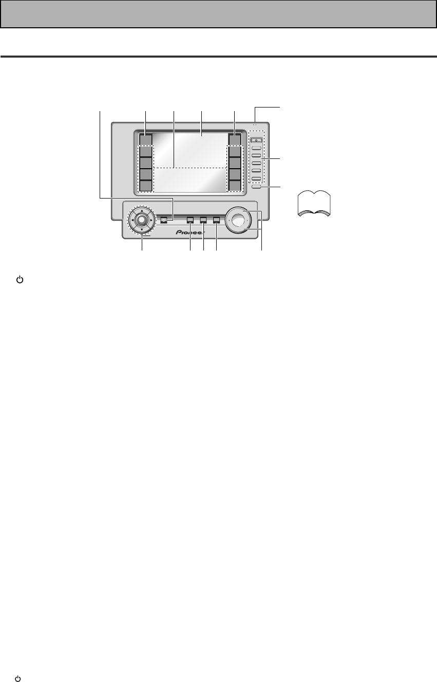
24
En
Displays & Controls
+
VOL
+
ENTER
AMP
DVD/LD
TV/SAT
VCR1
VCR2
REMOTE
SETUP
MD/TAPE1
CD
LINE1
TUNER
TV
CONTROL
FUNCTION
TV
CONTROL
MUTING
MASTER VOLUME
SYSTEM
OFF
MULTI
OPERATION
STANDBY/ON
–
VOL
–
CH
–
CH
+
FUNCTION
BACK LIGHT
use lock
on/off
12345
7
6
8
9
0=
~-
Remote Control
These pages describe the buttons on the remote control used to operate the amplifier. Since the screen on this
LCD remote control changes when you select a different function, explanations of buttons for controlling other
components/functions can be found in the sections for those components/functions.
To turn on the remote control
touch it anywhere on the screen
memo
1 STANDBY/ON button
Press to turn power of the amplifier on or to
STANDBY (off).
2AMP button
Press to switch the remote control into amplifier
mode or to get amplifier screens.
3Function buttons
These buttons are the basic controls that switch
the mode of the amplifier and allow you to control
your other components.
DVD/LD: Press to switch the remote control into
DVD/LD mode.
TV/SAT: Press to switch the remote control into
TV/SAT (satellite tuner) mode.
VCR 1: Press to switch the remote control into
VCR 1 mode.
VCR 2: Press to switch the remote control into
VCR 2 mode.
MD/TAPE 1: Press to switch the remote control
into MD/TAPE 1 mode.
CD: Press to switch the remote control into CD
mode.
LINE/TUNER: Press to switch the remote control
into LINE/TUNER mode.
TV CONTROL: Press so that the remote control
can operate the TV CONTROL commands.
4
REMOTE CONTROL screen (See p.25-26)
5REMOTE SETUP button.
Use to customize the remote control functions
and the remote control itself. (See “Remote
Control of Other Components“ starting on p.52)
6LOCK switch
Use to lock the remote control so it doesn't turn
on by accident. For normal use keep it set in USE.
7TV CONTROL buttons
The following buttons are used to control the TV
only and can be used once they are preset to
control your TV.
STANDBY/ON : Press to turn the power of the
TV on/off.
FUNCTION : Press TV FUNC to select the TV for
remote control operation.
CH +/– : Use these buttons to change the channel
of the TV.
VOL +/– : Press to control the volume of the TV.
8FUNCTION button
Press to select a source. The button will cycle
through all the possible sources.
9MASTER VOLUME button
Use to raise or lower the volume of the amplifier.
0MUTING button
Press to mute or restore the volume.
-SYSTEM OFF button (see p.70-71)
This button turns off components in two ways.
First, when pressed it will turn off all PIONEER
components. Secondly, any component that has
programmed into the SYSTEM OFF settings will
be turned off.
For example : If you programmed power off in the
SYSTEM OFF settings for your TV and VCR,
pressing the SYSTEM OFF button will turn off
these components even if they are not PIONEER
products.
=MULTI OPERATION button
Use this button to start the MULTI OPERATION
mode. See p.68-69 for how to program and use
the MULTI OPERATION mode.
~5˜∞(BACK LIGHT on/off)˜2˜3˜ENTER
buttons
These buttons can be used for a variety of
operations. In the SYSTEM SETUP menu, the
5˜∞ buttons can be used to adjust CHANNEL
DELAY or CHANNEL LEVEL.
The 5˜∞ buttons, pressed simultaneously, can be
use to lock or unlock a setting (see p.55).
These buttons are also used to control the DVD
menu for the DVD remote control screen. If the
reomte control is in the REMOTE SETUP mode
you can use the ∞ button to adjust the
BACKLIGHT (see p.29).
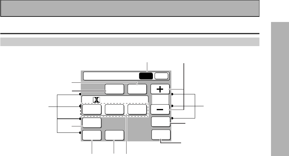
25
PREPARATION
En
Displays & Controls
Basic Amplifier LCD Screens
Amplifier MAIN Screen
1
3
4 4
67
2
8
9
50
-
MAIN SUB
DSP STEREO
THX
ADVANCED
THEATER
EFFECT
STANDARD
MIDNIGHT
LOUDNESS
SIGNAL
SELECT
DIGITAL
NR
/ dts / MPEG
MULTI CH
IN
Amplifier
1Amplifier MAIN button
Press this button to select the main amplifier
screen (above) when the remote control is on the
sub amplifier screen.
2STEREO button (See p.43,46,51)
Switches the amplifier into STEREO mode if it
was in a different sound mode (like ADVANCED
THEATER or THX CINEMA) or toggles between
DIRECT and STEREO mode.
3DSP button (See p.43)
Press repeatedly to select a DSP sound mode.
4 DIRECT FUNCTION on/off indicator
(See p.72)
These dots indicate weather the DIRECT
FUNCTION is on or off for the function (DVD/LD,
CD, etc.) they point to.
5MIDNIGHT button (See p.48)
Switches the MIDNIGHT LISTENING mode on or
off (for all modes except THX and MULTI CH IN).
6DIGITAL NR button (See p.48)
Switches the DIGITAL NR on or off (for all modes
except THX and MULTI CH IN).
7LOUDNESS button (See p.49)
Switches the LOUDNESS mode on or off (for all
modes except THX and MULTI CH IN).
82/dts/MPEG buttons (See p.41-45,73-
74)
Press these buttons to put the amplifier in the
selected surround sound mode. For more
information on the modes see p.41-45.
9SIGNAL SELECT button (See p.47)
Press SIGNAL SELECT repeatedly to select one of
the following:
ANALOG : To select an analog signal.
DIGITAL : To select a digital signal (DVD/LD, TV/
SAT, CD, MD/TAPE 1, VCR 1, VCR 2).
AC-3 RF : To select an 2 RF signal (DVD/LD, TV/
SAT, VCR 1, VCR 2).
AUTO : This is the default. If there are analog,
digital and 2 RF signals input, the amplifier
automatically selects the 2 RF signal. If there are
analog and digital signals input the digital will be
selected.
0 MULTI CH IN button (See p.50)
Use to hook up an external component that can
decode other types of signals and input them into
the VSA-E08.
-EFFECT +/– button
Use these buttons to increase or decrease the
amount of effect applied in a DSP or Advanced
Theater mode. When the amount of effect is
increased in a DSP/Advanced Theater mode the
characteristics of that mode become stronger and
more noticeable. The scale ranges from 10-90 with
70 as the default setting. First turn on the DSP/
Advanced Theater mode you want (by pressing the
DSP/Advanced Theater button until you get the
mode) and then increase or decrease the amount
of effect.
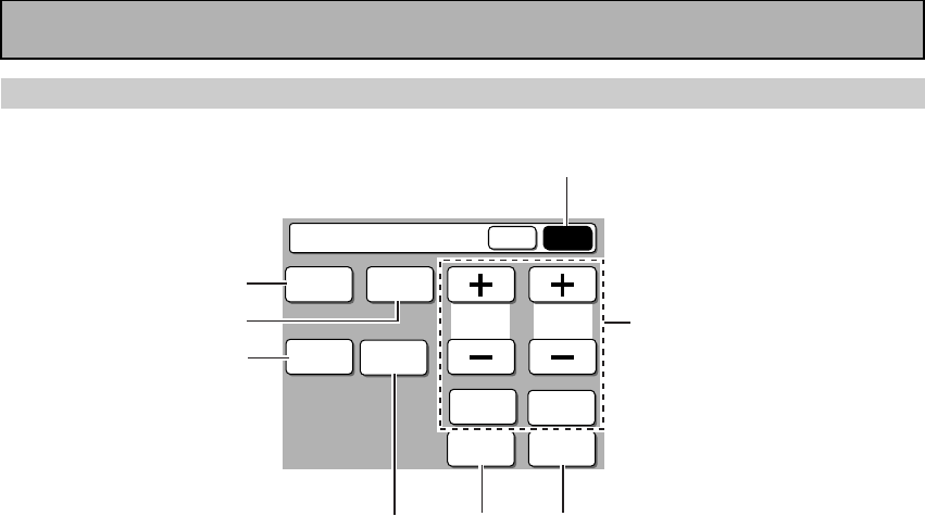
26
En
Displays & Controls
Amplifier SUB Screen
SPEAKER
A/B
TONE CH
SELECT
MAIN SUB
TREBLE
SYSTEM
SETUP
CH
LEVEL
INPUT
ATT.
BASS
FL
DIMMER
TAPE 2
MONITOR
Amplifier
1
2
3
4
567
8
1Amplifier SUB button
Press this button to select the sub amplifier screen
(above) when the remote control is on the main
amplifier screen.
2TAPE 2 MONITOR button (see p.66)
Selects the tape deck (or MD recorder, etc.)
connected to the TAPE 2 MONITOR inputs/
outputs. Allows monitoring of a recording as it's
being made.
3FL DIMMER button (See p.51)
Use to adjust the brightness of the main
display.
4INPUT ATT button
Use to lower the input level of an analog signal
that is too powerful, thus causing the amplifier to
distort (the overload indicator will be flashing
furiously).
5SPEAKER A/B button
Use to select the speaker system. A is the
primary setting. It plays all speakers hooked up
to the A system. A & B setting only plays the
front speakers of both the A & B systems and
the sub-woofer. Multi channel sources will be
down-mixed to these speakers so no sound will
be lost. B setting only plays the front speakers
connected to the B system and multi channel
sources will be down-mixed to these two
speakers. The button cycles through the
speaker systems as follows: A]B]A&B]off.
6CH LEVEL button (See 35-36)
Use this feature to adjust the level of individual
speakers during playback of a source.
7SYSTEM SET UP button
Use to set up the speaker and sound systems. For
more information see “Setting for Surround
Sound“
starting on p. 30.
8TONE control buttons
TONE button
This button has two functions. Firstly, it
switches between TONE on and TONE BY-
PASS, which bypasses the tone circuitry.
Secondly, you need to press the button before
using the CHANNEL SELECT buttons to adjust
the BASS & TREBLE.
CH SELECT button
Switches the tone adjust controls between the
FRONT, CENTER, SURROUND and
SURROUND BACK speakers. You can then use
the BASS and TREBLE controls to adjust the
sound.
BASS & TREBLE (+/–) buttons (See
p.49)
Use to adjust the high and low frequencies.
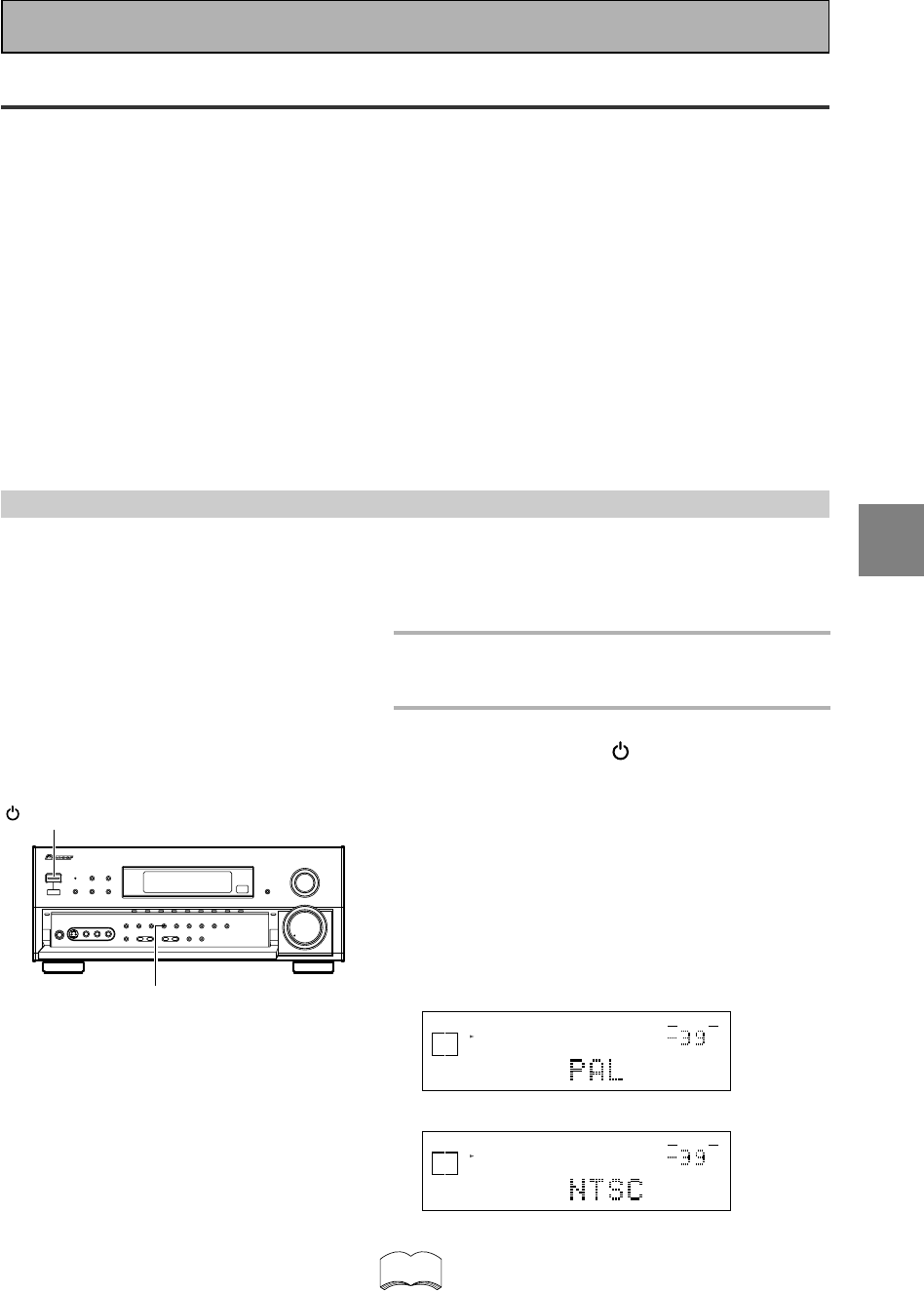
SET
UP
27
En
Initial Set Up
On Screen Display
There are a number of possible ways to hook up the amplifier to your video components, like a DVD player, and
hook up to your amplifier to your TV, but some of them won't allow you to use the on-screen display of this unit.
To avoid this one simply needs to follow two rules.
1Always use the same type of video cords to hook up your video components to the amplifier as you use to
hook up the amplifier and your TV. For example, if you use composite video cords to hook up your DVD and
the amplifier, use composite video cords to hook up the amplifier to your TV. If you use S video cords to hook
up your DVD and the amplifier, use S video cords to hook up the amplifier to your TV.
2Always make sure your TV is set to the appropriate input channel (for example, video 1). Your TV may have a
number of input channels and if you don't select the proper one you won't be able to use this receiver's on-
screen display, or, in fact, see any picture from this amplifier at all. If you are unsure how to choose an input
channel for your TV, refer to the manual which came with your TV.
You might, for example, use both composite and S video cords to hook up your video components with this
amplifier and then use composite video cords to hook up this amplifier to your TV. This arrangement would still
NOT let you see the on screen displays from this amplifier on your TV. The best idea is just to use one type of
video cord for all your video component and TV hook ups.
Switching video system between PAL and NTSC
This amplifier is able to use two types of video systems for its OSD (on screen display) either PAL or NTSC. If
you don't match the system on the amplifier with your home system no OSD will appear on your TV. The default
setting is PAL. If you use this system you don't need to make any settings here. People with multi-system TVs,
don’t need to worry about changing the setting. If necessary, follow the instructions below to switch the type of
video system.
1
Put the amplifier in the STANDBY
mode.
2
While holding down the LOUDNESS
button press the STANDBY/ON
button.
The video system type will change depending on the
state the receiver was previously in. The new type,
either PAL or NTSC, will appear in the display. It will
be shown for about seven seconds and then the
receiver returns to normal operating mode.
To change the video system type again repeat steps 1
and 2.
Make sure you press the LOUDNESS button, using
others buttons may change this receiver’s settings.
dB
SIGNAL
SELECT
SP A
DIGITAL
VOLUME
When a PAL system is selected
dB
SIGNAL
SELECT
SP A
DIGITAL
VOLUME
When a NTSC system is selected
When using the PAL setting the OSD does not get
displayed in color.
memo
LOUDNESS
STANDBY/ON
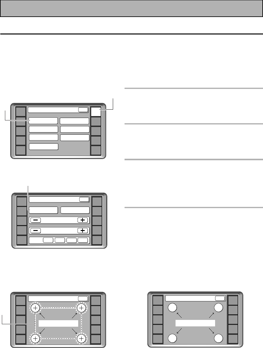
28
En
Setting Up the Remote Control
Since this remote is based on LCD screens, you should try and get used to the touch-sensitive nature of the
buttons as well as the way in which different screens control different operations. You can move between the
different screens with the function buttons on the left and right and/or certain buttons within each screen. The
BACK button will always return the remote control to the previous screen. In the explanations below you must
complete the TOUCH PANEL ADJUSTMENT setup to use the remote control properly. After that you can adjust
various basic settings to suit your personal preferences.
1
Press REMOTE SETUP on the
remote control.
Access to the different setup modes appear on your
remote control screen.
2
Press the LCD COMMANDER
button.
The different types of possible adjustments will
appear on the screen.
3
Since you must first align the touch
panel to make sure the remote
control responds properly when you
touch it, press the TOUCH PANEL
ADJUSTMENT button.
4
Press each cross point in the middle
to align the remote control touch
panel with the LCD panel
underneath.
This adjustment will make sure your remote control is
calibrated correctly.
When you've touched all four cross points the screen
will show the word "COMPLETE" and automatically
return to the LCD COMMANDER screen.
Initial Set Up
«
AMP
DVD/LD
TV/SAT
VCR1
VCR2
REMOTE
SETUP
MD/TAPE1
CD
LINE/
TUNER
TV
CONTROL
Touch Panel Adjust
COMPLETE
BACK
AMP
DVD/LD
TV/SAT
VCR1
VCR2
REMOTE
SETUP
MD/TAPE1
CD
LINE/
TUNER
TV
CONTROL
KEY RENAME
ITEM MEMO
Remote Setup
LCD
COMMANDER
MULTI OPERATION
DIRECT FUNCTION
PRESET RECALL
LEARNING
BACK
1
2
AMP
DVD/LD
TV/SAT
VCR1
VCR2
REMOTE
SETUP
MD/TAPE1
CD
LINE/
TUNER
TV
CONTROL
BEEP OFF 1 2 3
LCD Commander
TOUCH PANEL
ADJUSTMENT BACK LIGHT ON
LCD CONTRAST
BACK
LCD TIMER :
10
SEC
3
4
AMP
DVD/LD
TV/SAT
VCR1
VCR2
REMOTE
SETUP
MD/TAPE1
CD
LINE/
TUNER
TV
CONTROL
Touch Panel Adjust
BACK
TOUCH CROSS POINT
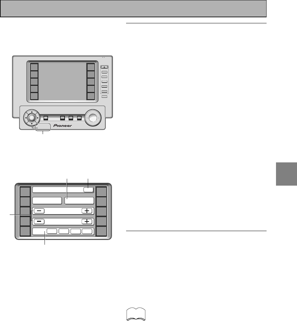
SET
UP
29
En
5
Decide which other adjustments
you‘d like to make and press those
buttons. The different possibilities
are:
BACKLIGHT : The backlight button let’s you choose
weather or not you want to have the backlight for this
LCD screen on or off. If you leave it on the screen is
easier to see but the remote consumes more power.
In a dark room you can simply push the REMOTE
SETUP button and then use the ∞ button to turn on
the BACKLIGHT.
LCD CONTRAST: You can lighten or darken the
contrast on the remote control screen. Use the – /+
buttons to change the contrast.
LCD TIMER: In order to save the battery a timer will
automatically turn the remote control off after a set
amount of time if no commands are entered. You can
choose how long the idle remote control will stay on
before the timer turns it off. You can set this function
in a range of 5-60 seconds. The default setting is 10
seconds. Use the – /+ buttons to adjust the number of
seconds for the timer setting.
(SYSTEM SETUP screens and REMOTE SETUP
screens, as well as the screens within those
operations, are all fixed to stay on 60 seconds. If no
command is entered they will turn off after 60
seconds.)
BEEP: When you have sent a command (pushed a
button) the remote control will beep once. You can
choose the sound of the beep from three different
possibilities here by pushing the appropriate button
(1,2,3). You can also turn the beep sound off.
6
When you are finished with the
adjustments you can press the
BACK button repeatedly to go back
to the AMPLIFIER screen. You can
also simply push the AMP button to
go back to the AMPLIFIER MAIN
screen.
You can press BACK anytime to go back a screen
or repeatedly to escape this set up mode.
Initial Set Up
6
memo
5
AMP
DVD/LD
TV/SAT
VCR1
VCR2
REMOTE
SETUP
MD/TAPE1
CD
LINE/
TUNER
TV
CONTROL
BEEP OFF 1 2 3
LCD Commander
TOUCH PANEL
ADJUSTMENT BACK LIGHT ON
LCD CONTRAST
BACK
LCD TIMER : 10 SEC
5
5
+
VOL
+
ENTER
AMP
DVD/LD
TV/SAT
VCR1
VCR2
REMOTE
SETUP
MD/TAPE1
CD
LINE/
TUNER
TV
CONTROL
FUNCTION
TV
CONTROL
MUTING
MASTER VOLUME
SYSTEM
OFF
MULTI
OPERATION
STANDBY/ON
–
VOL
–
CH
–
CH
+
FUNCTION
BACK LIGHT
use lock
on/off
5
(BACK LIGHT)
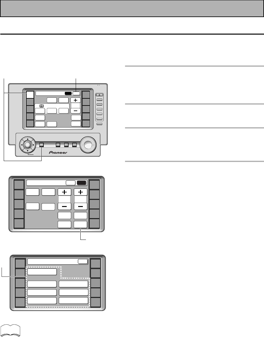
30
En
Setting Up for Surround Sound
To ensure the best possible surround sound, complete the following set up operations. You only need to make
these settings once (unless you change the placement of your current speaker system or add new speakers,
etc.). These set up operations use your TV to display the settings and choices so be sure your TV and amplifier
are properly hooked up.
When you press SETUP OK to complete one of
the settings explained on the right, a mark
consisting of four curved lines appears on the
top right of the remote control. This means the
remote control is sending the commands to
the amplifier. If the amplifier has gotten the
commands the word “received” appears in the
display on the amplifier. During this process
you must keep the remote control pointed at
the amplifier so the command can be
communicated from the remote control to the
amplifier. To cancel press the BACK button,
you will return to the SYSTEM SETUP menu.
memo
1
Turn on the amplifier and your TV,
press the AMP on the remote
control.
Make sure your TV is set to the amplifier.
2
Press the SUB button on the
amplifier screen.
3
Press the SYSTEM SETUP button.
Access to the different set up modes appear on your
remote control screen. These set up possibilities will
also appear on your TV.
4
Follow the order below to set up
your speakers for surround sound.
In each mode, the current settings are displayed
automatically. We suggest you adjust all these
settings when you first hook up the amplifier. That
gets them out of the way and you won't need to
return to this setting mode unless you change your
home set up by adding new speakers (etc.).
DIGITAL INPUT SELECT (See p.31)
In order to use your digital components you must match
the numbered digital input buttons with the numbered
digital jacks used by your digital components.
SPEAKER SETTING (See p.32-33)
Use to specify the type and number of speakers you
connected.
CHANNEL DELAY (See p.34)
You must add distance settings to all your speakers
for the most realistic surround sound. Adding a slight
delay to some speakers enhances sound separation
and is particularly important for achieving a surround
sound effect. You need to figure out the distance from
your listening position to your speakers to add the
proper delay.
CHANNEL LEVEL (See p.35-36)
Use to balance the volumes of your different speakers.
CROSSOVER NETWORK (See p.37)
This feature lets you select which bass frequencies
will be sent to the subwoofer or front speakers when
set to large.
BASS PEAK LEVEL MANAGER (See p.38)
Dolby Digital and DTS audio sources include ultra-low
bass tones. Set the bass peak level as needed to
prevent the ultra-low bass tones from distorting the
sound from the speakers.
DYNAMIC RANGE CONTROL (See p.39)
This feature makes possible excellent surround sound
effects when listening to Dolby Digital sources at low
volumes.
3
2
+
VOL
+
ENTER
AMP
DVD/LD
TV/SAT
VCR1
VCR2
REMOTE
SETUP
MD/TAPE1
CD
LINE/
TUNER
TV
CONTROL
FUNCTION
TV
CONTROL
MUTING
MASTER VOLUME
SYSTEM
OFF
MULTI
OPERATION
STANDBY/ON
–
VOL
–
CH
–
CH
+
FUNCTION
BACK LIGHT
use lock
on/off
Amplifier
MAIN SUB
DSP STEREO
THX
ADVANCED
THEATER
EFFECT
STANDARD
MIDNIGHT
LOUDNESS
MULTI CH
IN
SIGNAL
SELECT
DIGITAL
NR
/ dts/MPEG
4
1
AMP
DVD/LD
TV/SAT
VCR1
VCR2
REMOTE
SETUP
MD/TAPE1
CD
LINE/
TUNER
TV
CONTROL
System Setup
SPEAKER
SETTING CROSSOVER
NETWORK
BASS PEAK LEVEL
MANAGER
DYNAMIC RANGE
CONTROL
DIGITAL INPUT
SELECT
CHANNEL DELAY
CHANNEL LEVEL
BACK
Initial Set Up
AMP
DVD/LD
TV/SAT
VCR1
VCR2
REMOTE
SETUP
MD/TAPE1
CD
LINE/
TUNER
TV
CONTROL
SPEAKER
A/B
TONE CH
SELECT
Amplifier
MAIN SUB
TREBLE
SYSTEM
SETUP
CH
LEVEL
INPUT
ATT.
BASS
FL
DIMMER
TAPE 2
MONITOR
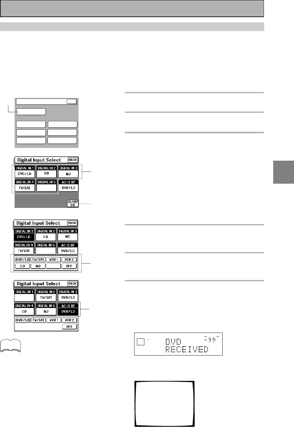
SET
UP
31
En
DIGITAL INPUT SELECT
In order to be able to use your digital equipment properly you need to assign digital inputs for each of the digital
components you connected. Match the DIGITAL IN buttons 1-5 with the digital jacks 1-5 in accordance with
what component is hooked up to each digital jack. Check the digital terminal numbers on the back of the
amplifier to make certain what component is in which jack (if necessary, see p.10 for more on digital
connections). Note that you can only assign a function (like DVD/LD) once after that it will disappear from the
choices from which you can assign buttons. The last button, the AC-3 RF button, is specifically for a DVD/LD or
LD player with an 2 RF output. If you connected one of these components match this button to the
component. If continuing from the previous page go to step 1. If starting fresh, complete steps 1-3 in “Setting
Up for Surround Sound“ (p.30) first.
1
Press the DIGITAL INPUT SELECT
button.
2
Press the DIGITAL IN button you
want to assign.
3
At the bottom of the LCD screen the
functions available will appear.
Press the button of the function you
want to assign to the selected
DIGITAL IN button.
This procedure assigns a digital function to the
DIGITAL IN. If you asssign a function (for example
DVD/LD) that has already been assigned to another
button the new button will get the function and the
old one will automatically turn to OFF. This is because
one function cannot be assigned twice.
If a digital jack has nothing connected to it set the
corresponding button to OFF.
4
Repeat step 2 & 3 until all the digital
in buttons correspond to the
components you connected.
5
If you hooked up a component to
the AC-3 RF channel use steps 2 & 3
to assign a function to it.
6
Press the SETUP OK button to
return the SYSTEM SETUP mode.
Hold the remote control pointed towards the amplifier
until you see the “RECEIVED” display on the
amplifier.
If "ERROR" flashes in the display, perform the setup
operations from the first step again.
dB
SIGNAL
SELECT
ANALOG
SP A
VOLUME
These settings will be displayed on your TV. (The
settings pictured here are the default settings.)
Digital-In Select
[DVD/LD]
[ CD ]
[ MD ]
[TV/SAT ]
[ VCR 1 ]
[DVD/LD]
Digital-1
Digital-2
Digital-3
Digital-4
Digital-5
AC-3 RF L
2
1
• For the DIGITAL IN 1-5 buttons you can choose
between DVD/LD, CD, TV/SAT, MD/TAPE 1/CD-
R, VCR 1/DVR and VCR 2 functions.
• For the AC-3 RF button you can choose between
DVD/LD, TV/SAT, VCR 1/DVR and VCR 2
functions. Remember, if you have a DVD/LD
player or LD player you should hook it up to the
analog and digital jacks in addition to the 2 RF
connection described here.
• To go back without entering any of the
information selected use the BACK button.
3
5
6
System Setup
SPEAKER
SETTING CROSSOVER
NETWORK
BASS PEAK LEVEL
MANAGER
DYNAMIC RANGE
CONTROL
DIGITAL INPUT
SELECT
CHANNEL DELAY
CHANNEL LEVEL
BACK
VCR1
LINE
OFF
memo
VCR1
Initial Set Up
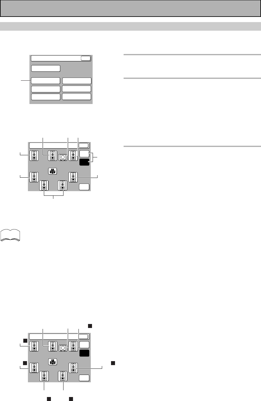
32
En
SPEAKER SETTING
The following steps show you how to select the correct set up for the type and number of speakers you
connected. If continuing from DIGITAL INPUT SELECT go to step 1. If starting fresh, complete steps 1-3 on p.30
first.
1
Press the SPEAKER SETTING
button.
2
Select the THX or FREE setting.
If you connected a complete set of THX speakers
Press THX. After that you only need to select the
number of SURROUND BACK speakers you have
(Step 3-5 below). Press the diagram of the
SURROUND BACK speakers to cycle through the
three choices: one, two or none and choose number
you have. Then go to step four.
If you do not have a THX speaker set up
Press FREE and follow the instructions below.
3
Specify the number and type of
speakers you connected by pressing
on the speakers in the diagram.
1Select Large (three dots) or small (two dots) for the
front speakers depending on whether your front
speakers can handle low bass sounds and whether
or not you hooked up a subwoofer.
2Select or deselect center speaker depending on
whether or not you hooked one up. Also choose
the size, large or small.
3Select or deselect subwoofer depending on
whether or not you hooked one up. Also select
PLUS if you have a subwoofer and want extra bass
sound.
4Select or deselect surround speakers depending
on whether or not you hooked them up. Also
choose large or small.
5Select or deselect surround back speakers depend-
ing on whether or not you hooked them up. Also
choose large or small and one or two.
Depending on your choices the sound will be
routed differently. For more information see
below.
FRONT (default setting is LARGE)
• Select small to send bass frequencies to the
subwoofer.
• Select large if your speakers will reproduce bass
frequencies effectively or if you did not connect a
subwoofer.
(If you select small for the front speakers the
subwoofer will automatically be switched YES.
Also, the center and surround speakers cannot be
set to large if the front speakers are set to small. In
this case, all bass frequencies are sent to the
subwoofer.)
CENTER (default setting is LARGE)
• Select large if your speaker will reproduce bass
frequencies effectively.
• Select small to send bass frequencies to the other
speakers or subwoofer.
• If you did not connect a center speaker, deselect it.
In this case, the center channel is output from the
front speakers.
«
To confirm what drawings represent which
speakers in the LCD display on your remtore control
see the diagrams below, which continue on to the
next page. You can choose two, one or no
SURROUND BACK speakers (and their size) by
repeatedly pressing on their image in the diagram.
1
memo
TWO (DOUBLE) SURROUND BACK
SPEAKERS
System Setup
SPEAKER
SETTING CROSSOVER
NETWORK
BASS PEAK LEVEL
MANAGER
DYNAMIC RANGE
CONTROL
DIGITAL INPUT
SELECT
CHANNEL DELAY
CHANNEL LEVEL
BACK
+++
+ +
++
Speaker Setting
SETUP
OK
FREE
THX
BACK
Front L
Center Front R
Sub
woofer
Surround L
Surround
back
Surround R
L
Surround
back R
Speaker Setting
SETUP
OK
FREE
THX
+++
+ +
++
3
-
1
3
-
4
3
-
4
3
-
2
3
-
5
3
-
3
3
-
1
2
BACK
Initial Set Up
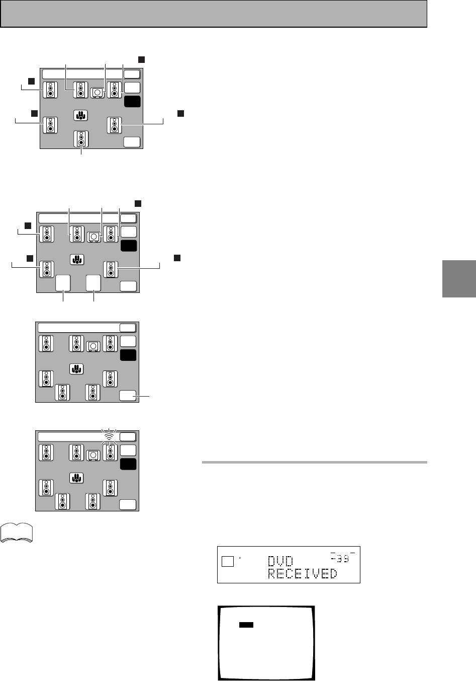
SET
UP
33
En
«
memo
If you have a subwoofer and like lots of bass, it may
seem logical to select LARGE for your FRONT
speakers and leave the subwoofer selected. This
may not, however, yield the best bass results.
Depending on the size and shape of your room you
may actually experience a decrease in the amount of
bass due to what is called "low frequency
cancellations." If you have a subwoofer, listen to the
bass response with the FRONT speakers set to
LARGE and SMALL alternatively and let your ears
judge which sounds best.
If you have a subwoofer, the safest option is to route
all the bass sounds to it by selecting SMALL for the
FRONT speakers.
SURROUND (default setting is LARGE)
• Select large if your speakers will reproduce bass
frequencies effectively.
• Select small to send bass frequencies to the other
speakers or subwoofer.
• If you did not connect surround speakers deselect
them. In this case, the sound of the surround
channels is output from the front and center
speakers.
• Remember, If you select small for the front
speakers, the SURROUND and SURROUND BACK
speakers can only be set to SMALL.
SURROUND BACK (default setting is LARGE X2)
NOTE: In order to use SURROUND BACK speakers
you need to hook them up through an external
amplifier (see p.20 for more on this.
• Select the number of SURROUND BACK speakers
you have. You can choose one speaker, two or
none.
• Select large if your speakers will reproduce bass
frequencies effectively.
• Select small to send bass frequencies to the other
speakers or subwoofer.
• If you did not connect surround back speakers
deselect them. In this case the boxes in the
diagram will appear empty, as shown on the left.
• If the FRONT speakers or the SURROUND
speakers are set to SMALL, the SURROUND BACK
speakers will automatically be set to SMALL.
• If you choose THX in step 2 then the SURROUND
BACK speakers can only be set to small (or off).
SUBWOOFER (default setting is YES)
• Leave it selected if you connected a subwoofer.
• If you did not connect a subwoofer deselect it. In
this case, the bass frequencies are output from the
front or surround speakers.
• Choose the PLUS setting if you want stronger
reproduction of deep bass sounds.
• If you select PLUS the bass frequencies that would
normally come out the front and center speakers
are all routed to the subwoofer.
• If you selected SMALL for the FRONT speakers
the subwoofer will automatically be set to on (you
won’t be able to choose off or PLUS).
4
Press the SETUP OK button to return
to the SYSTEM SETUP MENU.
Hold the remote control pointed towards the amplifier
until you see the “RECEIVED” display on the
amplifier.
If "ERROR" flashes in the display, perform the setup
operations from the first step again.
dB
SIGNAL
SELECT
ANALOG
SP A
VOLUME
The settings you chose will be displayed on your TV.
Speaker Setting
[LARGE]
[LARGE]
[LARGE]
[LARGEx2]
[ YES ]
Front L
Center
Surround
SurrBack
Subwoofer
[FREE] [THX]
4
ONE (SINGLE) SURROUND BACK SPEAKER
NO SURROUND BACK SPEAKERS
+++
+
++
Speaker Setting
SETUP
OK
FREE
THX
Front
L
Center Front
R
Sub
woofer
Surround
L
Surround
R
Surround back
BACK
+++
++
Speaker Setting
SETUP
OK
FREE
THX
Front
L
Center Front
R
Sub
woofer
Surround
L
Surround
R
Surround back (not hooked up)
BACK
+++
+ +
++
Speaker Setting
SETUP
OK
FREE
THX
BACK
+++
+ +
++
Speaker Setting
SETUP
OK
FREE
THX
BACK
Initial Set Up
Next, proceed to
CHANNEL DELAY below.
If you want to change a
setting before
proceeding
simply press the button of
the speaker you want to
change.
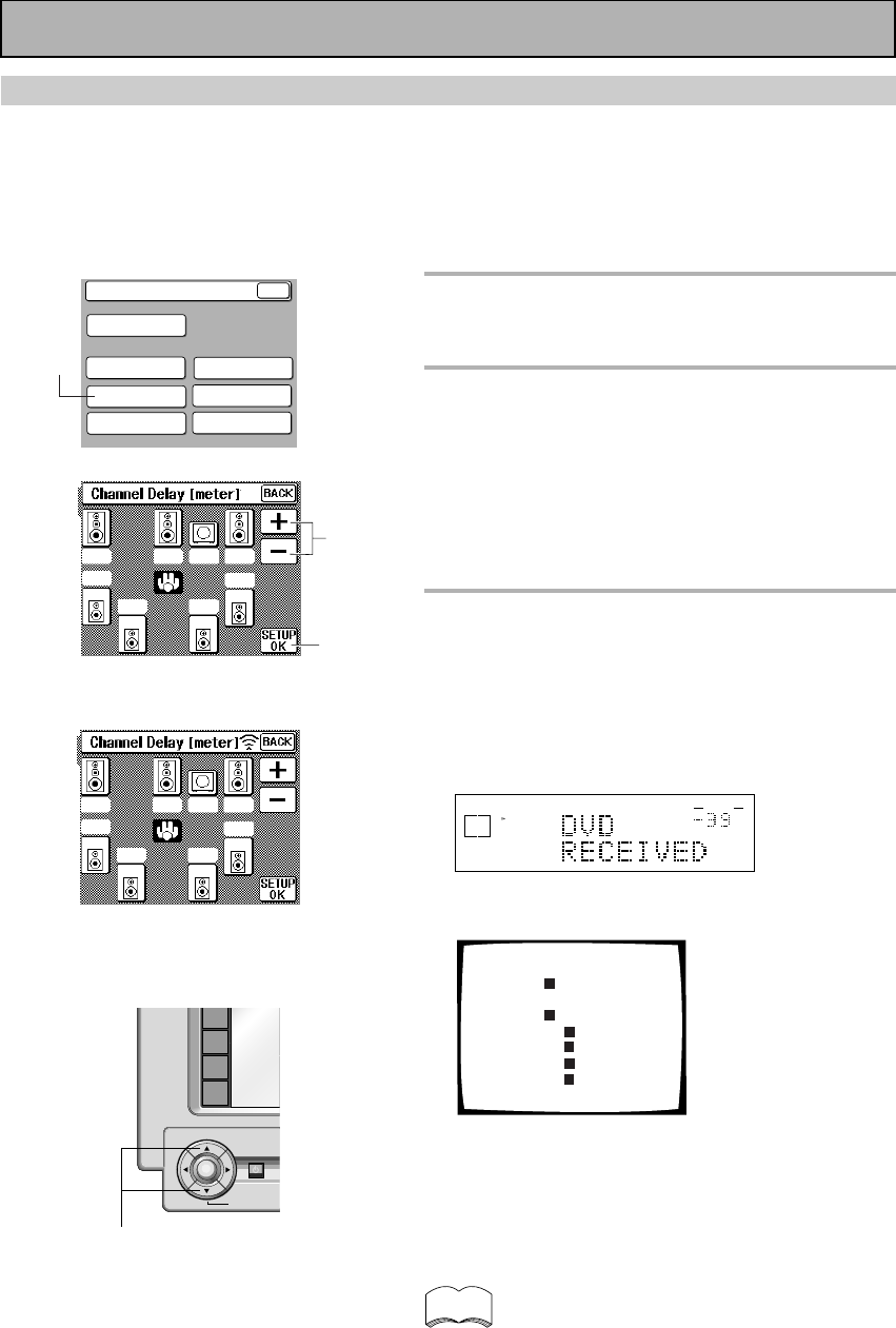
34
En
System Setup
SPEAKER
SETTING CROSSOVER
NETWORK
BASS PEAK LEVEL
MANAGER
DYNAMIC RANGE
CONTROL
DIGITAL INPUT
SELECT
CHANNEL DELAY
CHANNEL LEVEL
BACK
1
Press the CHANNEL DELAY button.
The CHANNEL DELAY speaker settings will appear on
your remote control screen.
2
Select each speaker by pressing its
button and use the +/– (or 5˜∞)
buttons to add or subtract the
distance in meter that the speaker is
from your normal listening position.
Adjust the speaker distance in 10 centi-meter
increments from 0.1 to 9 meters.
The default setting is 2 meters.
3
Press the SETUP OK button to
return to the SYSTEM SETUP
MENU.
Hold the remote control pointed towards the amplifier
until you see the “RECEIVED” display on the
amplifier.
If "ERROR" flashes in the display, perform the setup
operations from the first step again.
dB
SIGNAL
SELECT
ANALOG
SP A
VOLUME
These settings will be displayed on your TV.
Channel Delay
[2.0m]
[2.0m]
[2.0m]
[2.0m]
[2.0m]
[2.0m]
[2.0m]
[2.0m]
Front L
Center
Front
Surround
SurrBack
SurrBack
Surround
Subwoofer
L
R
R
L
R
L
Next, proceed to CHANNEL LEVEL below.
If you want to change a setting before proceeding
Start over from step one.
You can use the 5˜∞ buttons at the bottom of
the remote control instead of the +/– buttons.
CHANNEL DELAY
Adding a slight delay to some speakers is necessary to achieve a surround sound effect. You need to figure out
the distance from your listening position to your speakers to add the proper delay. The following steps show you
how to set the delay time for each channel by specifying the distances from your listening position to each
speaker. Once you specify the speaker distances, the amplifier calculates the correct delay times automatically.
If continuing from SPEAKER SETTING go to step 1. If starting fresh, complete steps 1-3 in “Setting Up for
Surround Sound“ (p.30) first.
1
«
5˜∞ buttons
ENTER
DVD/LD
TV/SAT
VCR1
VCR2
STANDBY/ON
BACK LIGHT
on/off
memo
3
2
2.0
2.0
2.0 2.0
2.0 2.0 2.0
2.0
Initial Set Up
2.0
2.0
2.0 2.0
2.0 2.0 2.0
2.0
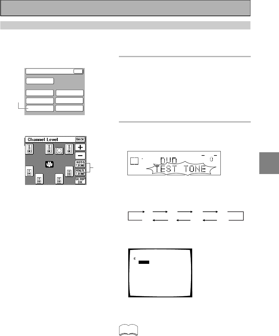
SET
UP
35
En
1
Press the CHANNEL LEVEL button.
The CHANNEL LEVEL settings will appear on your
remote control screen.
NOTE : Be prepared! The test tone is output at a
high volume level.
MASTER VOLUME rotates to the reference position
(0 dB) and the display on the amplifier flashes TEST
TONE. After a few seconds the test tone is output.
These settings will be displayed on your TV.
2
Select a test tone mode by pressing
one of the TEST TONE buttons.
Output the TEST TONE.
dB
STEREO
SIGNAL
SELECT
ANALOG
SP A
AUTO
VOLUME
AUTO (automatic TEST TONE)
This mode switches the test tone between each
speaker automatically. The automatic test tone is
output in the following order :
MANUAL (manual TEST TONE)
This mode lets you switch the test tone between
each speaker manually.
Any time you want to exit the process
Press SETUP OK.
• Be careful, if you touch one of the speaker but-
tons by accident the TEST TONE will automati-
cally sound from each speaker.
• If your subwoofer has a volume control, set it
to the middle position before doing these
operations.
• A test tone will be output from the SURROUND
BACK speakers but your external amplifier must
be turned up at least a little in order to hear it.
Be careful that it is not turned up too much be-
cause the test tone volume is quite loud.
CHANNEL LEVEL
The following steps show you how to balance the sound output level of your speakers. Proper speaker balance
is essential for obtaining high quality surround sound. If continuing from CHANNEL DELAY go to step 1. If
starting fresh, complete steps 1-3 in “Setting Up for Surround Sound“ (p.30) first.
memo
1
System Setup
SPEAKER
SETTING CROSSOVER
NETWORK
BASS PEAK LEVEL
MANAGER
DYNAMIC RANGE
CONTROL
DIGITAL INPUT
SELECT
CHANNEL DELAY
CHANNEL LEVEL
BACK
2
Initial Set Up
FL CT FR SR
SBL SBR
SL
SW
0.0
dB
0.0
dB
FL CT
0.0
dB
FR
0.0
dB
SW
0.0
dB
SL
0.0
dB
SBL
0.0
dB
SBR
0.0
dB
SR
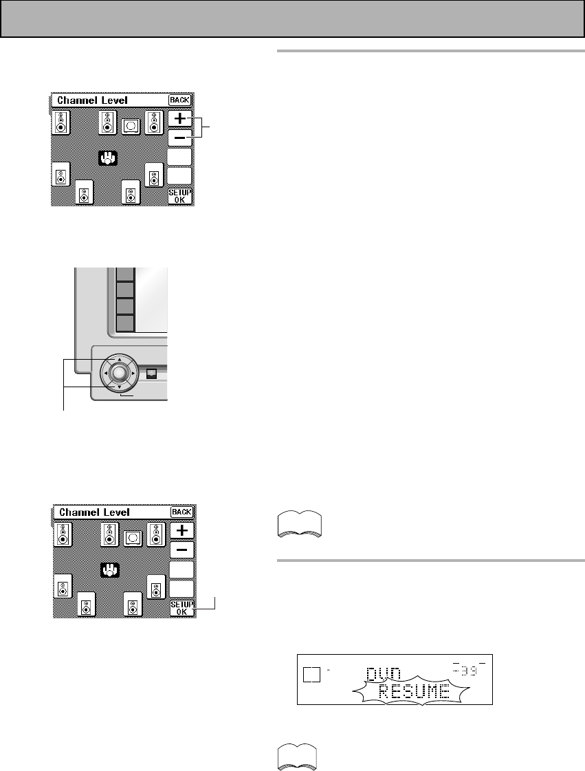
36
En
3
Using the remote control display,
follow the instructions below to
adjust the speaker levels so that you
hear the test tone at the same
volume from each speaker when
seated in your normal listening
position.
NOTE : The volume of the subwoofer tends to sound
lower than it actually is. You may need to adjust the
level after testing with an actual soundtrack.
In AUTO mode
1Use the +/– (or 5˜∞) buttons to adjust the level of
the speaker outputting the test tone. The tone will
automatically switch between speakers after
sounding for 2-3 seconds.
2Adjust the level of all speakers.
In MANUAL mode
1Use the +/– (or 5˜∞) buttons to adjust the level of
the first (the front left) speaker.
2Press the button on the touch panel for the next
speaker.
3Repeat 1 and 2 for each speaker.
If you are using a Sound Pressure Level (SPL)
meter
Take the readings from your main listening position
and adjust the level of each speaker to 75 dB SPL (C-
weighted/slow model).
You can use the 5˜∞ buttons at the bottom of
the remote control instead of the +/– buttons.
4
When all the speaker levels have
been set, select SETUP OK to return
to the SYSTEM SETUP MENU.
The display on the amplifier will say RESUME and the
MASTER VOLUME will return to its original position.
dB
STEREO
SIGNAL
SELECT
ANALOG
SP A
AUTO
VOLUME
Next, proceed to CROSSOVER NETWORK below.
Note that it is also possible to set channel levels
temporarily. Go to the AMPLIFIER SUB screen and press
CH LEVEL. Then follow the same procedure as explained
on this page. This function is designed to be used when
you want to change the levels temporarily to hear one
speaker louder. Using this method you can set speaker
levels in different modes, such as 2/dts, STEREO, and
each DSP mode, independently. You should return the
settings to their original state when done. Doing the set up
procedures on this page will erase any temporary/
independent level settings that have been made.
memo
memo
3
4
5˜∞ buttons
ENTER
DVD/LD
TV/SAT
VCR1
VCR2
STANDBY/ON
BACK LIGHT
on/off
AUTO
T.TONE
MANUAL
T.TONE
AUTO
T.TONE
MANUAL
T.TONE
Initial Set Up
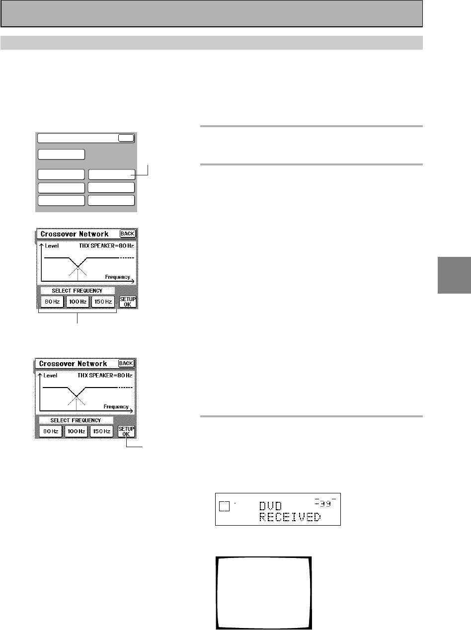
SET
UP
37
En
CROSSOVER NETWORK
The following steps show you how to adjust the crossover network. The crossover network is the frequency at
which the system divides the signal and sends the different parts (high, mid, low) to different speakers.
Speaking precisely, this setting sets the cutoff point for the bass frequencies rerouted from your SMALL
speakers to your subwoofer or speaker set to LARGE. If continuing from CHANNEL LEVEL go to step 1. If
starting fresh, complete steps 1-3 in “Setting Up for Surround Sound“ (p.30) first.
1
Press the CROSSOVER NETWORK
button.
2
Choose a crossover frequency.
Setting speakers to SMALL in SPEAKER SETTING
sends the respective channel's bass frequencies to
the subwoofer or the speakers you have selected as
LARGE. This function lets you determine which
frequencies will be sent to the subwoofer or LARGE
speakers. Press 80 Hz, 100 Hz, or 150 Hz. The default
setting is 80Hz.
80 Hz
Sends bass frequencies below 80 Hz to the
subwoofer (or LARGE speakers).
100 Hz
Sends bass frequencies below 100 Hz to the
subwoofer (or LARGE speakers).
150 Hz
Sends bass frequencies below 150 Hz to the
subwoofer (or LARGE speakers).
As noted on the LCD screen the THX setting is 80.
Select this setting if you have THX approved SMALL
speakers.
Experiment with the different settings to see which
sounds best to you.
3
Press the SETUP OK button to
return to the SYSTEM SETUP
MENU.
The display on the amplifier reads RECEIVED.
If "ERROR" flashes in the display, perform the setup
operations from the first step again.
dB
SIGNAL
SELECT
ANALOG
SP A
VOLUME
This information will be displayed on your TV.
Crossover Network
[ 80Hz]
Frequency
(THX Speaker = 80Hz)
Next, proceed to BASS PEAK LEVEL MANAGER
below.
If you want to change a setting before proceeding
Start over from step one.
1
2
3
System Setup
SPEAKER
SETTING CROSSOVER
NETWORK
BASS PEAK LEVEL
MANAGER
DYNAMIC RANGE
CONTROL
DIGITAL INPUT
SELECT
CHANNEL DELAY
CHANNEL LEVEL
BACK
Initial Set Up
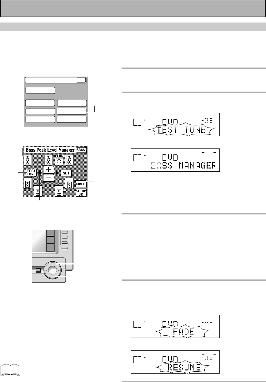
38
En
1
Press the BASS PEAK LEVEL
MANAGER button.
2
Press the TEST TONE button.
The MASTER VOLUME rotates to MIN (----dB).
dB
STEREO
SIGNAL
SELECT
ANALOG
SP A
AUTO
VOLUME
dB
STEREO
SIGNAL
SELECT
ANALOG
SP A
AUTO
VOLUME
A test tone will sound or not depending on which
speakers you have selected. If subwoofer is YES (or on
PLUS) the test tone will only sound from the
subwoofer. If the subwoofer is off and the front and
surround speakers are set to large, front and surround
speakers will sound the test tone.
3
Use the +/– buttons (or the MASTER
VOLUME +/– on the bottom right of
the remote control or the MASTER
VOLUME on the front panel) to
specify the bass peak level.
1Raise the level gradually.
2Set the bass peak level at the point just before the
tone starts to distort.
4
Press the SET button to input the
level.
The display on the amplifier will say RESUME and the
MASTER VOLUME will return to its original position.
dB
STEREO
SIGNAL
SELECT
ANALOG
SP A
AUTO
VOLUME
dB
STEREO
SIGNAL
SELECT
ANALOG
SP A
AUTO
VOLUME
5
Press the SETUP OK button.
You may need to experiment with different Dolby Digital
sources before you can get the BASS PEAK LEVEL set
correctly.
If you want to change a setting before proceeding
Start over from step one.
BASS PEAK LEVEL MANAGER
The LFE (Low Frequency Effect) channel in Dolby Digital,DTS or MPEG program sources can produce heavily
concentrated ultra-low bass tones that may exceed the capabilities of your speaker system. The following steps
show you how to set the peak level for the ultra-low bass (LFE) channel. If continuing from CROSSOVER
NETWORK go to step 1. If starting fresh, complete steps 1-3 in "Setting Up for Surround Sound" (p.30) first.
«
«
1
MASTER VOLUME +/–
CANCEL
45
+
VOL
+
CD
LINE/
TUNER
TV
CONTROL
MUTING
MASTER VOLUME
M
–
VOL
–
CH
–
FUNCTION
2
3
If you press CANCEL no settings are input to
the amplifier but the screen remains on the
remote control. To escape the screen you
must press SETUP OK.
memo
System Setup
SPEAKER
SETTING CROSSOVER
NETWORK
BASS PEAK LEVEL
MANAGER
DYNAMIC RANGE
CONTROL
DIGITAL INPUT
SELECT
CHANNEL DELAY
CHANNEL LEVEL
BACK
Initial Set Up
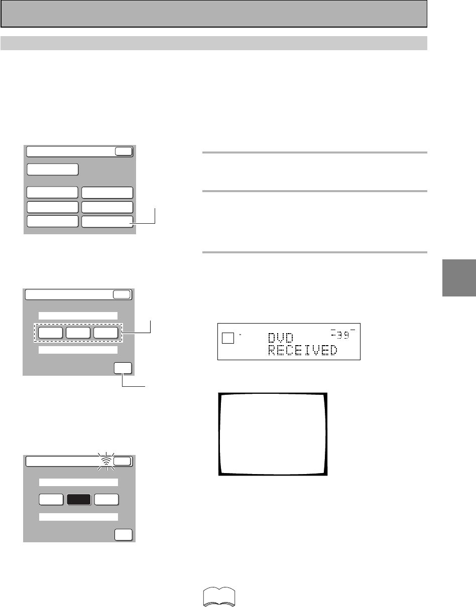
SET
UP
39
En
DYNAMIC RANGE CONTROL
This feature makes it possible to enjoy full surround sound effects on Dolby Digital sources even at low
volumes. It does this by compressing the dynamic range. Dynamic range is the difference between the loudest
and the softest sounds in any given signal. Compressing the range plays sounds so the quieter ones are audible
and the louder ones don’t get distorted or become overpowering. This feature only applies to Dolby Digital
sources but the MIDNIGHT LISTENING mode (explained on p.48) accomplishes the same end for a variety of
sources. If continuing from BASS PEAK LEVEL MANAGER go to step 1. If starting fresh, complete steps 1-3 in
“Setting Up for Surround Sound“ (p.30) first.
1
Press the DYNAMIC RANGE
CONTROL button.
2
Choose the amount of DYNAMIC
RANGE CONTROL, OFF, MID or
MAX, you want.
The default setting is OFF.
3
Press the SETUP OK button.
Hold the remote control pointed towards the amplifier
until you see the “RECEIVED” display on the
amplifier.
If "ERROR" flashes in the display, perform the setup
operations from the first step again.
dB
SIGNAL
SELECT
ANALOG
SP A
VOLUME
This information will be displayed on your TV.
Dynamic Range Control
Select Mode [MID]
(For Dolby Digital)
If you want to change a setting before proceeding
Start over from step one.
You may need to experiment with different Dolby
Digital sources before you can use the DYNAMIC
RANGE CONTROL setting to suit your low volume
listening needs.
If you are listening at loud volumes we
recommend turning the Dynamic Range Control
OFF.
2
3
«
memo
Dynamic Range Control
BACK
SELECT MODE
FOR DOLBY DIGITAL
OFF MID MAX
SETUP
OK
Dynamic Range Control
SELECT MODE
FOR DOLBY DIGITAL
OFF MID MAX
SETUP
OK
BACK
SPEAKER
SETTING CROSSOVER
NETWORK
BASS PEAK LEVEL
MANAGER
DYNAMIC RANGE
CONTROL
DIGITAL INPUT
SELECT
CHANNEL DELAY
CHANNEL LEVEL
System Setup
BACK
1
Initial Set Up
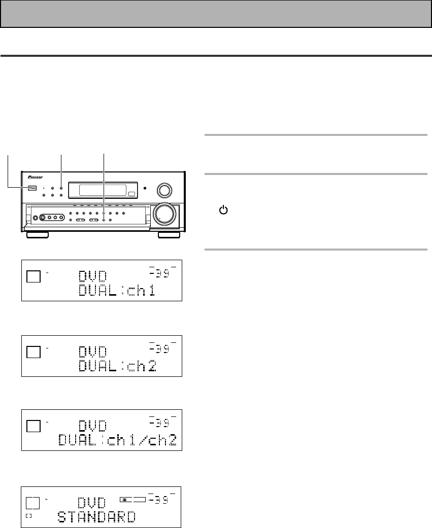
40
En
DUAL MONO SETTING
The dual mono setting can only be used when listening to Dolby Digital discs that have dual mono software
encoded in them. Dual mono software usually is used to put two different soundtracks on one DVD. With this
setting you can choose which channel in the dual mono setting you want to listen to. Thus, it is useful for
soundtracks that have one language on one channel and a different language on the other. Remember this
setting is only applicable if you are using Dolbly Digital software with dual mono and want to isolate one of the
channels therein. Otherwise, just ignore this function.
1
Put the amplifier in STANDBY
mode.
2
While holding down the VIDEO
SELECT button press the
STANDBY/ON button on the
front panel.
3
You will see DUAL in the display for
about five seconds. During this
time use the STEREO/DIRECT
button to cycle through the
different DUAL MONO settings to
find the one you want.
The different settings are: DUAL ch1, where you only
hear channel 1; DUAL ch2, where you only hear
channel 2; and DUAL ch1/ch2, where you hear both
channels, but independently from different speakers.
The default setting is DUAL ch1.
dB
STEREO
SIGNAL
SELECT
ANALOG
SP A
VOLUME
DUAL ch1 setting
dB
STEREO
SIGNAL
SELECT
ANALOG
SP A
VOLUME
dB
STEREO
SIGNAL
SELECT
ANALOG
SP A
VOLUME
DUAL ch1/ch2 setting
3
12
DIGITAL
dB
SIGNAL
SELECT
AC-3
SP A
L
DIGITAL
VOLUME
When DUAL MONO is
playing with ch 1 selected
the L will light. When
playing with ch 2 selected
the R will light. When
playing with ch 1/2 selected
the L and R will light.
DUAL ch2 setting
Initial Set Up

OPERATION
OPERATION
41
En
Basic Playback
Sound Modes
The five sound modes on the receiver are explained here. These can be turned on from the front panel or from
the AMPLIFIER MAIN SCREEN on the remote control.
There are three cinema modes: STANDARD, HOME THX CINEMA, and ADVANCED THEATER. These are
designed to be used with multi channel surround sound audio/visual sources (like DVDs and LDs). Intrinsic to
home theater, these modes can deliver realistic and powerful surround sound that recreates the movie theater
experience. You may need to experiment with them to see which settings suit your home system and personal
tastes.
The DSP and STEREO modes are designed to be used with music sources but some DSP modes are also suited
for film soundtracks. Again, try different settings with various soundtracks to see which you like.
You must choose one of the three cinema modes or the DSP mode in order to get surround sound. In STEREO
mode only the front two speakers, and sometimes the subwoofer (if you have one), are used.
STANDARD modes
This mode is for pure decoding of Dolby Digital, Dolby Pro Logic, DTS or MPEG. No special effects are added. It
is good for enjoying regular movies/videos that have been recorded in Dolby Digital, Dolby Pro Logic, DTS or
MPEG. STANDARD 7.1 is also the basic mode for enjoying sources with SURROUND BACK channels. If you
play an MPEG disc the receiver will automatically go into MPEG audio. For more detailed information see
p.74.You will only be able to access the second two modes if you have hooked up SURROUND BACK speakers.
For more detailed information see p.18,20,32-33. The display will show you what kind of source (Dolby Digital,
DTS, etc.) is being played.
STANDARD
Use this mode with sources that do not have SURROUND BACK channels. If you don't have SURROUND
BACK speaker(s) switched on (see p.32-33) this is the only THX mode you will be able to select on the
amplifier.
STANDARD 7.1
This mode is best for sources with SURROUND BACK channels. You will only be able to access this mode if
you have set the SURROUND BACK speakers in the SPEAKER SETTING procedure (see p.32-33). Also, this
mode will play 5.1 channels sources and other sources through all the speakers you have hooked up, routing
some of the sound into your SURROUND BACK channel or channels. STANDARD 7.1 will appear in the
display even if you only have one SURROUND BACK speaker hooked up. The display will change according
to the source played.
STANDARD AUTO
In this mode the receiver will automatically select the appropriate STANDARD mode and use it to play the
soundtrack. You will only be able to access this mode if you have set the SURROUND BACK speakers in the
SPEAKER SETTING procedure (see p.32-33). If the source has a Surround EX marker then the receiver will
automatically go into STANDARD 7.1 mode. This mode is best if you are unsure which of the above
STANDARD modes to use. The display will change according to the source played.

42
En
Basic Playback
ACTION
This mode is designed for action movies, which generally use lots of sound effects. The mode enriches the
sound to make it more realistic and extends the parameters to pick up high and low sound effects.
5/7-D THEATER
This mode is especially designed to give sound depth to stereo sources. The overall effect builds a
dynamic and broad sound space, allowing two-channel (stereo) signals to faithfully imitate a five speaker
sound. The mode should be used in conjunction with Dolby Pro Logic for sources bearing the
DOLBY SURROUND
mark.
When a Dolby Digital soundtrack is played back the Dialog Normalization function of the receiver acti-
vates automatically. Dialog Normalization is a Dolby Digital function that establishes the average dialog
level for the program source being played. If the amplifier's level does not match the average dialog
level, first you see "DIAL NORM" flash in the amplifier's display and next "OFFSET +4 dB" (as an ex-
ample) will appear. In this example, the number +4 dB is the difference between the receiver's gain
structure and the Dolby Digital average dialog level. To match the average dialog level, subtract or add
the OFFSET level. For example, if the OFFSET level is +4 dB, the amplifier's output is 4 dB over the
average recorded level.
memo
ADVANCED THEATER modes
The Advanced Theater mode is a newly designed system for enhancing movie soundtracks and other audio-
visual sources. It incorporates the use of DTS as well as Dolby Digital into its sound processing. These
functions switch on automatically when the source you are playing is encoded with DTS or Dolby Digital. There
are four Advanced Theater settings that use DSP (Digital Signal Processing) to create different types of sound
environments. If you have SURROUND BACK speakers or (even just one) speaker switched on (see p.32-33)
then 7.1 will appear after the name of all of these modes in the display on the amplifier. The display will show
you what kind of source (Dolby Digital, DTS, etc.) is being played.
MUSICAL
This mode is primarily for music and adds a spacious feeling to the sound. A long delay time of reflected
sounds, provides resonant tones which emulate a concert hall.
DRAMA
This mode is designed for movies with a lot of dialog. The elements of dialog are enhanced, making the
characters seem more real. The mode also compresses the dynamic range somewhat so loud sounds do
not overpower softer ones (compare this with the MIDNIGHT LISTENING mode explained on p. 48).
HOME THX CINEMA modes
THX is a set of technical standards created by Lucasfilm, Ltd. These standards were designed to emulate a film
sound stage and thus reproduce, with the greatest possible accuracy, the soundtrack intended by the filmmakers.
To get THX sound use one the three modes explained below. You will only be able to access the second two
modes if you have hooked up SURROUND BACK speakers. For more detailed information see p.18,20,32-33.
This mode is best if you are unsure which of the above THX modes to use. The display will show you what kind
of source (Dolby Digital, DTS, etc.) is being played.
THX CINEMA
Use this mode to get THX sound with sources that do not have SURROUND BACK channels. If you don't
have SURROUND BACK speaker(s) switched on (see p.32-33) this is the only THX mode you will be able to
select on the amplifier.
THX SURROUND EX
This mode is specifically for using your SURROUND BACK channels with either SURROUND EX sources or
5.1 channel sources. You will only be able to access this mode if you have set the SURROUND BACK
speakers in the SPEAKER SETTING procedure (see p.32-33). If the source you are using is a 5.1 source then
this mode will route some of the sound to the SURROUND BACK channel(s). If the source you are using
does not have a SURROUND EX marker or is not a 5.1 source then the display will automatically change to
THX CINEMA.
THX AUTO
In this mode the receiver will automatically select the appropriate THX mode and use it to play the
soundtrack. You will only be able to access this mode if you have set the SURROUND BACK speakers in the
SPEAKER SETUP procedure (see p.32-33). If the source has a Surround EX marker then the amplifier will
automatically go into THX SURROUND EX mode. This mode is best if you are unsure which of the above
THX modes to use.

OPERATION
OPERATION
43
En
Basic Playback
STEREO mode
Use the STEREO mode to enjoy standard (two-channel) stereo sound from the front left and right speakers.
This mode is most like the sound reproduction you would get from a regular stereo receiver or amplifier that is
not equipped to handled A/V formats as this one is. You might want to use this mode for listening to regular
music sources (like CDs) but remember, you will only get sound from your front two speakers (and possibly your
subwoofer).
DSP modes
The DSP (Digital Signal Processing) modes allow you to transform your living room into a variety of different
sonic environments when playing either two-channel or multi-channel sources. If you have SURROUND BACK
speakers switched on (see p.32-33) then 7.1 will appear after the name of all of these modes in the display on
the amplifier.
HALL 1
Simulates the acoustic effects of a large concert hall. Suitable for classical music. A long delay time of
reflected sounds, coupled with reverb effects, let the listener enjoy the dynamic and rich sounds
characteristic of concert halls and powerful orchestral performances.
HALL 2
Simulates the acoustic environment of a very resonant concert hall. Rich reverberation and a full sound
create the impression of a lively performance space.
JAZZ
Simulates the acoustic effects of a jazz club. Reflected sound is virtually below 100 msec so that the
listener can enjoy a live band effect.
DANCE
Simulates the acoustic effects of a dance club. Features a strong bass sound.
Reflected sound delay time is virtually below 50 msec, for the listener to enjoy the visceral power of dance
music.
THEATER 1
Reproduces theater sound field effects without losing the localization of each channel. Theater effects can
be enjoyed without losing Dolby Digital/ Pro Logic effects when used in combination those formats (with
movies bearing the
DOLBY SURROUND
trademark).
THEATER 2
Simulates the acoustic environment of a theater while maintaining proper localization of each channel.
5/7CH STEREO
Simulates the acoustic environment of a regular stereo while using all the speakers in the system to induce
a rich, all-around sound. If you have SURROUND BACK speakers switched on (see p.32-33) then the name
of this mode will be 7CH STEREO in the display on the receiver. If the SURROUND BACK speakers are
switched off, then the mode will appear as 5CH STEREO.
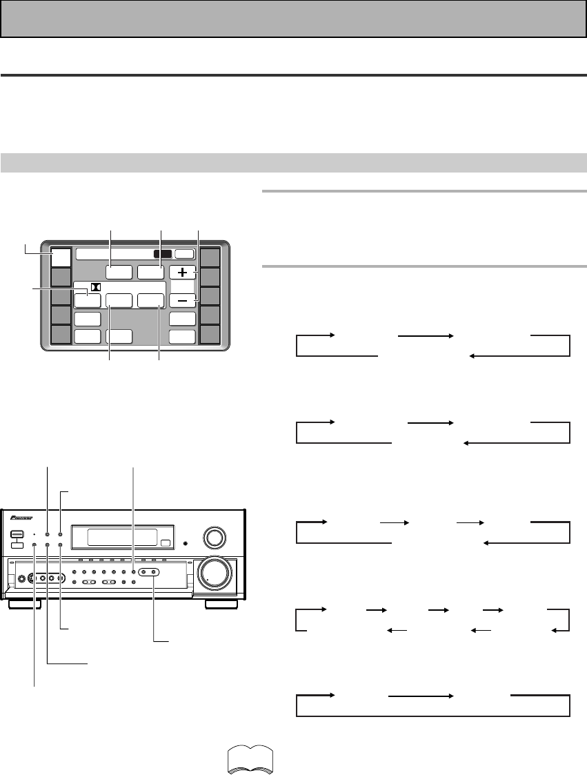
44
En
Basic Playback
1
Press the AMP.
This sets the remote to select the sound mode.
(You can skip this step when using the controls on
the amplifier.)
2
Select the sound mode.
• For STANDARD \ Press STANDARD
Each press changes the STANDARD mode as follows:
STANDARD STANDARD 7.1
STANDARD auto
• For HOME THX CINEMA \ Press THX(THX CINEMA
on the front panel).
Each press changes the THX mode as follows:
THX CINEMA THX SURR EX
THX AUTO
• For ADVANCED THEATER \ Press ADVANCED
THEATER(ADVANCED on the front panel)
Each press changes the ADVANCED THEATER mode
as follows:
MUSICAL DRAMA ACTION
5/7-D THEATER
• For DSP modes \ Press DSP(DSP MODE on the
front panel) repeatedly
Each press changes the DSP mode as follows:
5/7CH STEREO THEATER 2 THEATER 1
HALL 1 HALL 2 JAZZ DANCE
• For STEREO \Press STEREO (STEREO/DIRECT on
the front panel)
Each press changes the STEREO mode as follows:
STEREO DIRECT
• If you have SURROUND BACK speakers switched on
(see p.32-33) then 7-D THEATER and 7CH STEREO
will appear as such in the display on the amplifier. If
these speakers are not switched on the above two
modes will appear as 5-D THEATER and 5CH
STEREO.
• The effects of ADVANCED THEATER mode can be
adjusted in the range of 10 to 90 by pressing EFFECT
+/– (The default setting is 70). Also, the effect level
can be set in each ADVANCED THEATER mode by
pressing the EFFECT(+/–) button.
• The amount of effect of each DSP mode can be
adjusted in the range of 10 to 90 (the default setting
value is 70) by pressing EFFECT +/–.
• 5/7CH STEREO modes cannot be changed.
Selecting a Sound Mode
To ensure the best possible surround sound, be sure to complete the set up procedures described in “Setting
Up for Surround Sound” (starting on page 30) before using the sound modes. This is particularly important when
using the 2(Dolby) Digital / MPEG or DTS sources. When using the sound modes, using SPEAKERS A will give
the best results. If you use SPEAKERS B the sound will be down mixed to the two front B speakers.
Using surround sound
DSP MODE
STEREO/
DIRECT
THX CINEMA
ADVANCED
STANDARD
memo
1
AMP
DVD/LD
TV/SAT
VCR1
VCR2
REMOTE
SETUP
MD/TAPE1
CD
LINE/
TUNER
TV
CONTROL
Amplifier
MAIN SUB
DSP STEREO
THX
ADVANCED
THEATER
EFFECT
STANDARD
MIDNIGHT
LOUDNESS
SIGNAL
SELECT
DIGITAL
NR
/ dts / MPEG
MULTI CH
IN
DSP STEREO EFFECT +/–
THX
ADVANCED
THEATER
STANDARD
EFFECT/
CH SELECT
+/–
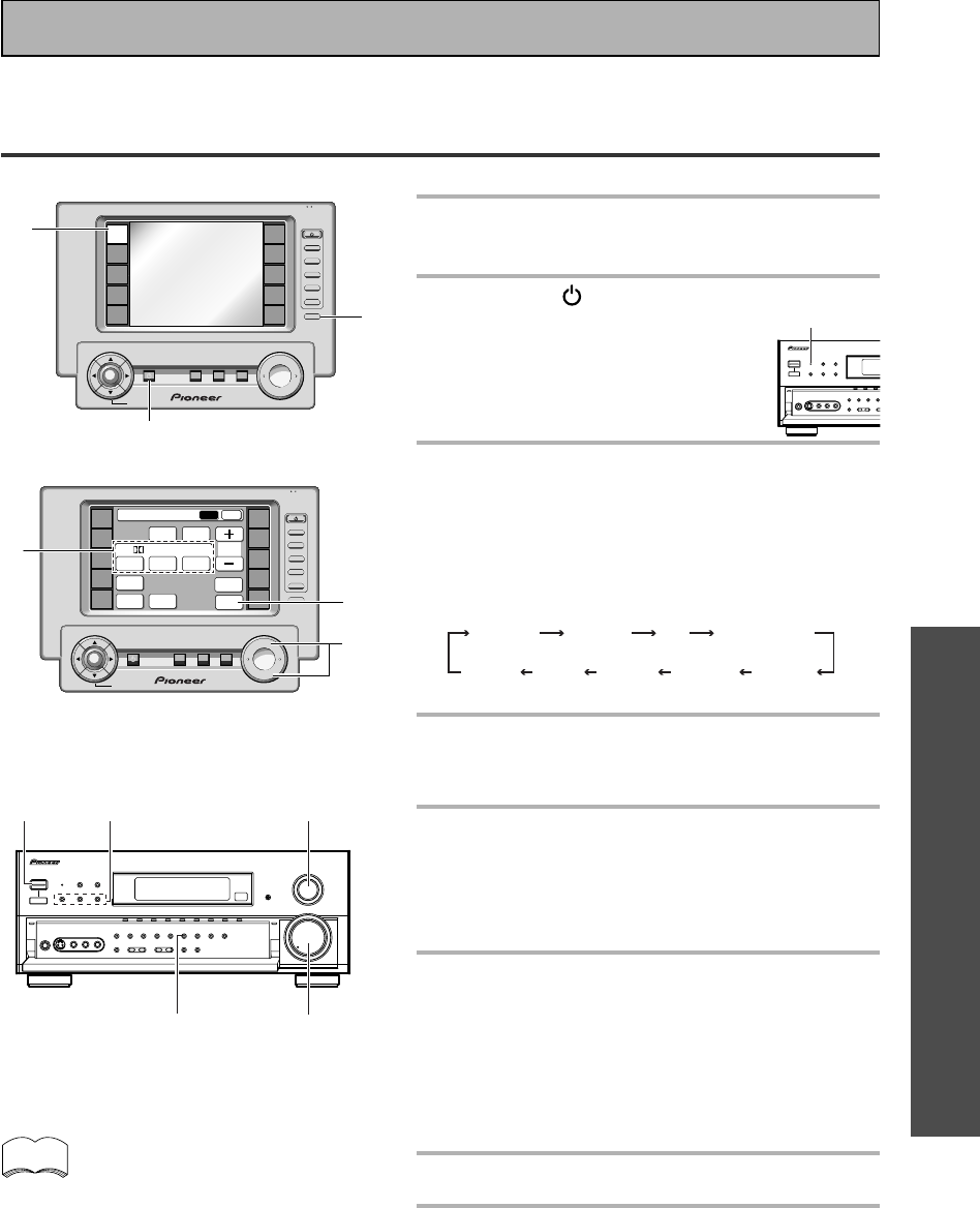
OPERATION
OPERATION
45
En
Playing Sources with Dolby Digital, MPEG or DTS
Sound
The following instructions show you how to play Dolby Digital, MPEG or DTS sound sources with the VSA-E08.
1
Turn on the power of the playback
component.
2
Press the STANDBY/
ON button to turn on the
amplifier.
Be sure that the standby indicator
turns off on the front panel.
3
Press the FUNCTION button on the
remore control to select the source
you want to playback.
Alternatively, Use the INPUT SELECTOR on the front
panel.
The FUNCTION button cycles through the sources in
the following order:
DVD/LD TV/SAT CD
VIDEO
VCR 1 PHONO
MD/TAPE 1
LINE/
TUNER
VCR 2
4
Press the AMP.
The AMPLIFIER MAIN SCREEN appears on the
remote.
5
Choose a 2/DTS/MPEG mode by
pressing THX, ADVANCED THEATER
or STANDARD.
You need to choose on of the modes to get surround
sound. For more see “Sound Modes,” on p.41-43.
6
Press the SIGNAL SELECT button
the input signal corresponding to
the source component (setting the
switch to AUTO assures the proper
signal will be selected).
(See “Switching ANALOG/DIGITAL signal input” on p.
47.)
7
Play a source (for example, a DVD).
8
Adjust the volume by using the
MASTER VOLUME buttons on the
remote control or the MASTER
VOLUME on the front panel.
Return to the AMPLIFIER screens (by pressing to
AMP button and SUB, if needed) to make other sound
adjustments like bass/treble, loudness etc.
memo
Basic Playback
4
+
VOL
+
ENTER
AMP
DVD/LD
TV/SAT
VCR1
VCR2
REMOTE
SETUP
MD/TAPE1
CD
LINE/
TUNER
TV
CONTROL
FUNCTION
TV
CONTROL
MUTING
MASTER VOLUME
SYSTEM
OFF
MULTI
OPERATION
STANDBY/ON
—
VOL
—
CH
—
CH
+
FUNCTION
BACK LIGHT
use lock
on/off
3
5
8
6
+
VOL
+
ENTER
AMP
DVD/LD
TV/SAT
VCR1
VCR2
REMOTE
SETUP
MD/TAPE1
CD
LINE/
TUNER
TV
CONTROL
FUNCTION
TV
CONTROL
MUTING
MASTER VOLUME
SYSTEM
OFF
MULTI
OPERATION
STANDBY/ON
—
VOL
—
CH
—
CH
+
FUNCTION
BACK LIGHT
use lock
on/off
Amplifier
MAIN SUB
DSP STEREO
THX
ADVANCED
THEATER
EFFECT
STANDARD
MIDNIGHT
LOUDNESS
SIGNAL
SELECT
DIGITAL
NR
/ dts / MPEG
MULTI CH
IN
8
3
5
2
6
(SIGNAL SELECT)
• We recommend using different modes for
different types of DTS material. For watching
movies, the STANDARD, THX or ADVANCED
THEATER setting should provide the best
results. For listening to music, the STANDARD,
DIRECT, STEREO, or DSP modes should serve
the listener best.
• Make sure you connect your DVD/LD or LD
players using the 2 RF jack. If your player has
an 2 RF output this will ensure you can use all
LDs. Refer to p.14.
STANDBY
indicator
2
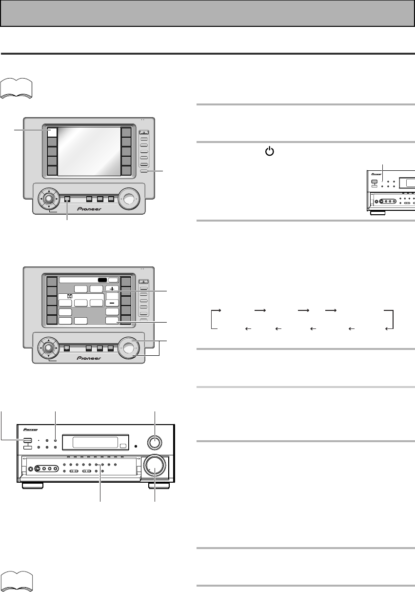
46
En
Playing Sources with Stereo Sound
The following instructions show you how to play audio or audio-visual sources with the VSA-E08.
If the TAPE 2 indicator is visible in the display, it means the TAPE 2 MONITOR is on. Press TAPE 2
MONITOR on the front panel to turn it off unless you want to listen to TAPE 2.
1
Turn on the power of the playback
component.
2
Press the STANDBY/
ON button to turn on the
amplifier.
Be sure that the standby indicator
turns off on the front panel.
3
Press the FUNCTION button on the
remore control to select the source
you want to playback.
Alternatively, Use the INPUT SELECTOR on the front
panel.
The FUNCTION button cycles through the sources in
the following order:
DVD/LD TV/SAT CD
VIDEO
VCR 1 PHONO
MD/TAPE 1
LINE/
TUNER
VCR 2
4
Press the AMP.
The AMPLIFIER MAIN SCREEN appears on the
remote.
5
Press the STEREO button to select
the stereo mode.
The STEREO indicator lights on the display.
6
Press the SIGNAL SELECT button
to select the input signal
corresponding to the source
component (setting the switch to
AUTO assures the proper signal will
be selected).
(See “Switching ANALOG/DIGITAL Signal Input” on
p.47.)
7
Start playback of the component
you selected in step 1.
8
Adjust the volume by using the
MASTER VOLUME buttons on the
remote control or the MASTER
VOLUME on the front panel.
Return to the AMPLIFIER screens (by pressing to
AMP button and SUB, if needed) to make other sound
adjustments like bass/treble, loudness etc.
If you are not able to get sound from the
amplifier the problem may well lie with
the SIGNAL SELECT switch. You need
to make sure the input is set to the
appropriate ANALOG or DIGITAL setting.
Refer to page 47 for more on this.
8
3
2
6
(SIGNAL SELECT)
2
4
3
6
8
+
VOL +
ENTER
AMP
DVD/LD
TV/SAT
VCR1
VCR2
REMOTE
SETUP
MD/TAPE1
CD
LINE/
TUNER
TV
CONTROL
FUNCTION
TV
CONTROL
MUTING
MASTER VOLUME
SYSTEM
OFF
MULTI
OPERATION
STANDBY/ON
–
VOL –
CH –
CH +
FUNCTION
BACK LIGHT
use lock
on/off
+
VOL +
ENTER
AMP
DVD/LD
TV/SAT
VCR1
VCR2
REMOTE
SETUP
MD/TAPE1
CD
LINE/
TUNER
TV
CONTROL
FUNCTION
TV
CONTROL
MUTING
MASTER VOLUME
SYSTEM
OFF
MULTI
OPERATION
STANDBY/ON
—
VOL —
CH —
CH +
FUNCTION
BACK LIGHT
use lock
on/off
Amplifier
MAIN SUB
DSP STEREO
THX
ADVANCED
THEATER
EFFECT
STANDARD
MIDNIGHT
LOUDNESS
SIGNAL
SELECT
DIGITAL
NR
/ dts / MPEG
MULTI CH
IN
memo
memo
Basic Playback
STANDBY
indicator
5
5
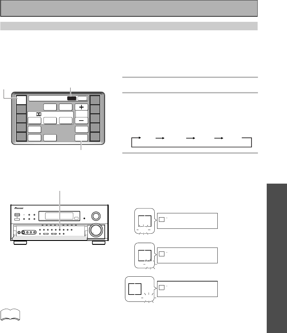
OPERATION
OPERATION
47
En
Switching ANALOG/DIGITAL Signal Input
This button selects the type of input, ANALOG, DIGITAL or 2 RF, sent to the amplifier. You need to take
special care to switch to the appropriate input when necessary. For example, the switch would have to be on
DIGITAL to hear DOLBY DIGITAL/MPEG or DTS surround sound material but it would have to be on analog to
record from the ANALOG out jacks on the amplifier. The default setting is AUTO which chooses digital when all
three are available but goes with whatever is available if it is the only choice.
1
Press the AMP.
2
Press the SIGNAL SELECT button to
select the input signal
corresponding to the format of the
source component.
Each press switches the signal in the order below:
AUTO ANALOG DIGITAL AC-3RF
3
While SIGNAL SELECT is set to
DIGITAL, AC-3 lights when a Dolby
Digital signal is input, and DTS
lights when a DTS signal is input
and MPEG lights when a MPEG
signal is input.
memo
Basic Playback
2
AMP
DVD/LD
TV/SAT
VCR1
VCR2
REMOTE
SETUP
MD/TAPE1
CD
LINE/
TUNER
TV
CONTROL
Amplifier
MAIN SUB
DSP STEREO
THX
ADVANCED
THEATER
EFFECT
STANDARD
MIDNIGHT
LOUDNESS
MULTI CH
IN
SIGNAL
SELECT
DIGITAL
NR
/ dts / MPEG
1
2
• In the AUTO setting, SIGNAL SELECT chooses the signal, based on availability, in the following order: AC-
3 RF, DIGITAL, ANALOG.
• If all the DIGITAL INPUT SELECT (see p.31) choices are set to OFF, the SIGNAL SELECT will default to
ANALOG.
• Because the audio from a karaoke microphone and LDs recorded with analog audio only is not output from
the digital output, set SIGNAL SELECT to ANALOG to listen to these formats.
• This amplifier can only play back Dolby Digital, PCM (32kHz, 44kHz, 48kHz, and 96kHz), and DTS and
MPEG digital signal formats. It cannot play back digital signals other than these so for those kinds of
formats you'll have to play them back in an analog manner (making sure your equipment is hooked up with
analog connections and setting the SIGNAL SELECT to ANALOG).
• When an LD or CD with DTS is played back with the SIGNAL SELECT set in ANALOG, digital noise caused
by playing back the DTS directly (with no decoding) is output. To prevent noise, you need to make digital
connections (See p.13) and set SIGNAL SELECT to AUTO.
• Some DVD players don’t output DTS and/or MPEG signals. For more details, refer to the instruction manual
supplied with your DVD player.
SIGNAL
SELECT
DTS
SP A
DIGITAL
SIGNAL
SELECT
AC-3
SP A
DIGITAL
SIGNAL
SELECT
DTS
DIGITAL
SIGNAL
SELECT
MPEG
SP A
DIGITAL
SIGNAL
SELECT
DIGITAL
SIGNAL
SELECT
AC-3
DIGITAL
MPEG
When a DTS signal is input.
When a Dolby Digital signal is input.
When a MPEG signal is input.
MAIN
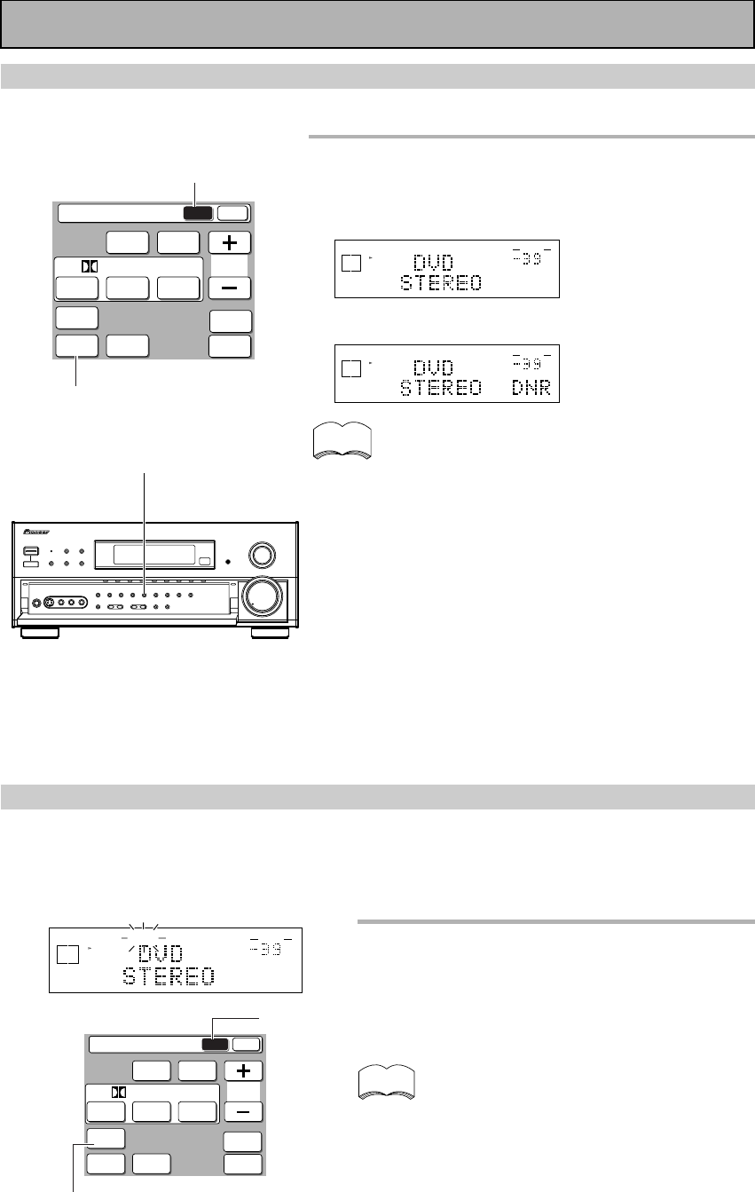
48
En
Listening in MIDNIGHT Mode
This feature makes it possible to get excellent surround sound effects even when listening at low volumes. It
can be used with a variety of surround sound sources and play soundtracks so that the quieter sounds are
audible while the noisier sounds don’t become overly loud or distorted. It does this by bringing all the sounds in
a given soundtrack closer together in volume. Compare this feature with the DYNAMIC RANGE CONTROL (for
Dolby Digital sources only) on p.39.
Press the MIDNIGHT button on the
remote control’s Amplifier MAIN
screen.
Each press switches MIDNIGHT LISTENING mode on
or off.
• The effect adjusts itself automatically in
accordance with the volume level.
• You can’t use the MIDNIGHT LISTENING mode
with the THX or MULTI CH IN modes.
• If you press MIDNIGHT when in DIRECT mode
the reciever switches to STEREO mode.
memo
MIDNIGHT
Amplifier
MAIN SUB
DSP STEREO
THX
ADVANCED
THEATER
EFFECT
STANDARD
MIDNIGHT
LOUDNESS
MULTI CH
IN
SIGNAL
SELECT
DIGITAL
NR
/ dts / MPEG
dB
STEREO
MIDNIGHTSIGNAL
SELECT
SP A
DIGITAL
AUTO
VOLUME
Basic Playback
memo
J
1
1
Amplifier
MAIN SUB
DSP STEREO
THX
ADVANCED
THEATER
EFFECT
STANDARD
MIDNIGHT
LOUDNESS
MULTI CH
IN
SIGNAL
SELECT
DIGITAL
NR
/ dts / MPEG
1
Press the DIGITAL NR button on the
remote control’s Receiver MAIN screen
or on the front panel.
Each press switches DIGITAL NR on or off.
dB
STEREO
SIGNAL
SELECT
SP A
DIGITAL
VOLUME
dB
STEREO
SIGNAL
SELECT
SP A
DIGITAL
VOLUME
• In cases described below, noises may not be reduced
even if DIGITAL NR is on.
· Sudden noise
· Extremely loud noise
· Signals that do not contain many high frequencies
• DIGITAL NR is effective at and above levels shown
below for each source.
• STEREO (excluding 96 kHz)
· analog input ......................... 10-18 dB
· digital input .......................... 10-15 dB
· AM/FM tuner ...................... 10-15 dB
• DSP/ADVANCED/STANDARD/96 kHz stereo
.................................................. 6-10 dB
• Depending on the condition of the source, there may
not be a noticeable improvement in the quality of the
sound.
• You can’t use the DIGITAL NR mode with the MULTI
CH IN or THX modes.
• If you press DIGITAL NR in DIRECT mode the receiver
will switch to STEREO mode.
Reducing Noise During Playback (DIGITAL NR Function)
To reduce extraneous noise switch on DIGITAL NR. This noise reduction can be used with every mode except
THX and MULTI CH IN.
MAIN
MAIN
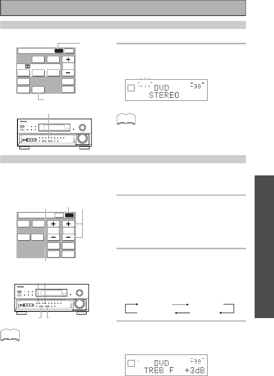
OPERATION
OPERATION
49
En
Basic Playback
Adjusting Bass and Treble (Tone Control)
You can use BASS +/– or TREBLE +/– buttons to adjust the low and high frequencies for each individual set of
speakers. If the amplifier is in STEREO mode you can only adjust the FRONT speakers. In a surround mode
(STANDARD, ADVANCED THEATER, etc.) you can adjust the FRONT, CENTER, SURROUND and SURROUND
BACK speakers. The TONE button can also be used to bypass the tone circuitry (see p.23).
memo
Listening in LOUDNESS Mode
The LOUDNESS mode allows you to boost the bass in a signal. It is useful for listening to music at low volumes.
Press the LOUDNESS button on the
remote control’s Amplifier MAIN
screen or on the front panel.
Each press switches LOUDNESS mode on or off.
dB
STEREO
LOUDNESSSIGNAL
SELECT
ANALOG
SP A
AUTO
VOLUME
• You can’t use the LOUDNESS mode with the
THX or MULTI CH IN modes.
• If you press LOUDNESS when in DIRECT mode
the reciever switches to STEREO mode.
memo
Amplifier
MAIN SUB
DSP STEREO
THX
ADVANCED
THEATER
EFFECT
STANDARD
MIDNIGHT
LOUDNESS
MULTI CH
IN
SIGNAL
SELECT
DIGITAL
NR
/ dts / MPEG
LOUDNESS
• The tone control can be adjusted in a range of
±6 dB.
• The tone control cannot be adjusted in THX,
MULTI CH IN.
• If the amplifier is in DIRECT mode and you
press the TONE button, TONE BYPASS will
appear in the display, letting you know that you
can't change the tone in DIERCT mode. Another
press cancels DIRECT mode.
LOUDNESS
CH
SELECT
TONE
SPEAKER
A/B
Amplifier
MAIN SUB
TREBLE
SYSTEM
SETUP
CH
LEVEL
INPUT
ATT.
BASS
FL
DIMMER
TAPE 2
MONITOR
33
1
TREBLE
BASS
CHANNEL SELECT
TONE
1
Press the TONE button on the
remote control's Amplifier or front
panel to put the amplifier in tone
adjust mode.
TONE: ON should appear in the display. If TONE:
BYPASS appears, press the button again to get
TONE:ON the tone adjust mode.
2
Press the CH SELECT button on the
remote control's Amplifier or
CHANNEL SELECT button on the
front panel to cycle through the
different tone adjust channels.
The button cycles though the possibilities in the
following order:
TONE Front TONE Center
TONE SurBack TONE Surr.
3
Use the BASS or TREBLE (+/–)
buttons to adjust the low or high
frequencies of each channel.
Display when using the TONE +/- buttons.
dB
STEREO
SIGNAL
SELECT
ANALOG
SP A
VOLUME
A few seconds after you finish adjusting the tone the
amplifier will revert to the sound mode it was in at the
begining of the process.
MAIN
SUB
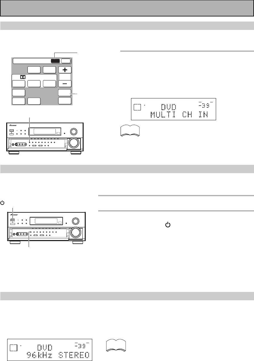
50
En
Basic Playback
MULTI CHANNEL IN Playback
MULTI CH IN allows you to connect an external decoder to enjoy certain types of specialized discs. To use
MULTI CH playback follow the instructions below.
memo
MULTI CH IN
Amplifier
MAIN SUB
DSP STEREO
THX
ADVANCED
THEATER
EFFECT
STANDARD
MIDNIGHT
LOUDNESS
MULTI CH
IN
SIGNAL
SELECT
DIGITAL
NR
/ dts / MPEG
MULTI CH IN
MULTI CHANNEL IN Setting
There are two types of MULTI CH IN settings: ADJUST and BYPASS. In the former you can change the sound
level and in the latter it's fixed. To move between the two settings follow the procedure below:
Press the MULTI CH IN button on
the remote control’s Amplifier MAIN
screen or the MULTI CH INPUT
button on the front panel.
Each press switches the input between the previous
mode and MULTI CH IN.
When MULTI CH IN is selected only the volume
level can be set. All of this unit’s other features
(DIGITAL NR etc.) cannot be used. Also, In BY-
PASS mode all speaker settings and other setup
settings have no effect.
1
Put amplifier in STANDBY.
2
While holding down the MULTI CH INPUT
button press the STANDBY/ON button.
The setting will change depending on what state the receiver was
previously in. For a few seconds the display will show you which
MULTI CH setting you are now in.
ADJUST: Use the ADJUST setting when you want to be able
to control each channel level individually.
BYPASS:
This setting is good for getting the cleanest possible signal.
In this setting you won’t be able to change each channel individually.
We recommend using BYPASS and the default setting is BYPASS.
MULTI CH INPUT
STANDBY/ON
dB
STEREO
SIGNAL
SELECT
SP A
DIGITAL
AUTO
VOLUME
memo
96 kHz 24 bit Performance
This amplifier is capable of playing back advanced DVD discs which are recorded in 96 kHz/24 bit format (these
are all stereo discs) and any source recorded in 96 kHz and up to 24 bit. The amplifier will automatically read the
format of the disc and play accordingly (of course the SIGNAL SELECT will have to set to AUTO or DIGITAL to
read the DVD soundtrack). When the amplifier plays a 96 kHz/24 bit disc "96 kHz" and whatever mode you're
using (for example "STEREO," "DIRECT or " DNR") will appear in the display.
• When a 96 kHz/24 bit disc is played back the volume
may be louder than that of a normal disc.
• Some DVD players cannot play 96 kHz/24 bit discs.
Check the manual of your DVD player to make sure.
• During this playback the player enters the STEREO
mode and you can use the controls available in
STEREO mode (LOUDNESS, MIDNIGHT, TONE
controls, etc., see p.48-49).
• With 96 kHz/24 bit discs you are able to use MULTI
CH IN playback and the TAPE 2 MONITOR.
• In 96 kHz/24 mode you can't use the STANDARD,
ADVANCED THEATER, THX, or DSP modes.
MAIN
dB
SIGNAL
SELECT
ANALOG
SP A
VOLUME
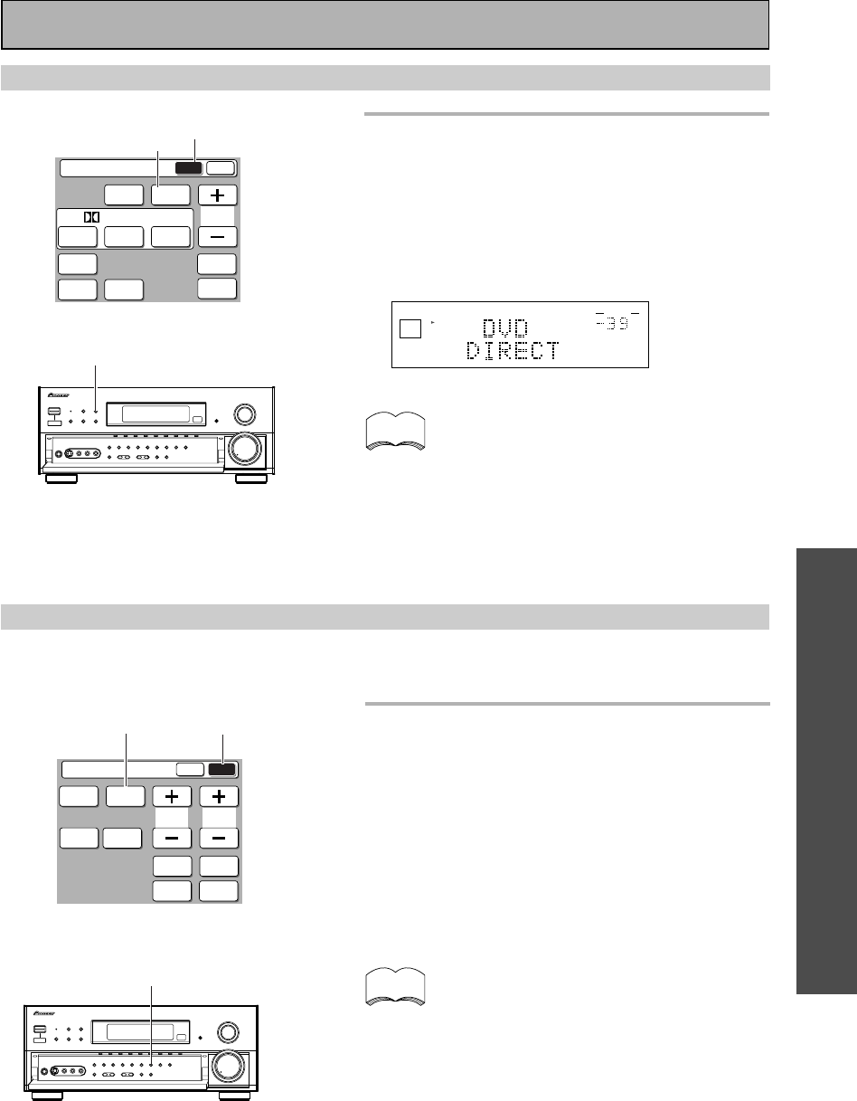
OPERATION
OPERATION
51
En
Adjusting the Brightness of the Display
Use the FL DIMMER button to adjust the brightness of the fluorescent display (FL=fluorescent display).
Use the FL DIMMER button on the
remote control's Amplifier SUB
screen or the front panel to
alternate between the different
levels of brightness.
Four levels of brightness ranging from very dim to
very bright can be selected. Each press changes the
brightness of the display. When cycling through the
options, the default brightness can also be selected.
Please note: It is a feature of this unit that the
fluorescent display will be brighter for a few
seconds after you choose a function (like DVD/
LD, CD, etc.) and then get softer. This will still
happen when you adjust the brightness but the
new setting will be the one the display softens to.
memo
Basic Playback
Direct Playback
Use the STEREO button on the
remote control or the STEREO/
DIRECT button on the front panel to
alternate between STEREO and
DIRECT mode.
The DIRECT mode will give you the most accurate
reproduction of two channel (stereo) sources but
won't let you add any effects to the sound.
dB
STEREO
SIGNAL
SELECT
ANALOG
SP A
VOLUME
• None of the tone controls or other sound modes
can be used with DIRECT playback.
• If the amplifier is in a different mode than
STEREO to start with the first push of the
STEREO button will put it in STEREO mode.
After that the button will toggle the amplifier
between STEREO and DIRECT mode.
• Relatedly, see the explanation of the TONE but-
ton on p.23 and the STEREO mode on p.43.
memo
Amplifier
MAIN SUB
DSP STEREO
THX
ADVANCED
THEATER
EFFECT
STANDARD
MIDNIGHT
LOUDNESS
MULTI CH
IN
SIGNAL
SELECT
DIGITAL
NR
/ dts / MPEG
STEREO
STEREO/DIRECT
FL DIMMER
CH
SELECT
TONE
SPEAKER
A/B
Amplifier
MAIN SUB
TREBLE
SYSTEM
SETUP
CH
LEVEL
INPUT
ATT.
BASS
FL
DIMMER
TAPE 2
MONITOR
FL DIMMER
MAIN
SUB
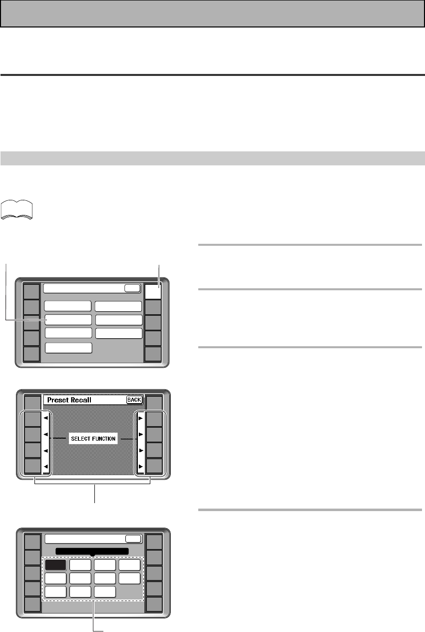
52
En
4
AMP
DVD/LD
TV/SAT
VCR1
VCR2
REMOTE
SETUP
MD/TAPE1
CD
LINE/
TUNER
TV
CONTROL
Preset Recall
DVD LD VCR TV
TAPE
CD-R
DVRTUNER
STB CD MD
SELECT ITEM
BACKDVD/LD][
1
Press the REMOTE SETUP.
The REMOTE SETUP menu appears on the remote
control's screen.
2
Press the PRESET RECALL button
on the remote control.
The step by step process will appear on the remote
control.
3
SELECT FUNCTION will appear on
the remote control. Choose the
button (for example, DVD/LD) you
want to assign to control the
component you want to operate .
Naturally it's easiest and most logical to assign the
button that has the same name as the component you
are setting up (for example, choose the CD button for
your CD player).
In some cases, however, you may need to assign a
button to a component with a different name.
For example, on button is marked MD/TAPE 1. If you
assign this button to your MD player you'll need to
use a different button, like VCR 2, for your tape deck.
4
Choose the component you want to
set up.
In the example in the diagram on the left, DVD was
selected in step 3. Thus, [DVD/LD] appears in the top
bar after Preset Recall.
Remote Control of Other Components
Setting Up the Remote Control to Control Other
Components
In addition to controlling the amplifier, the supplied remote control can operate your other components (VCR, TV,
LD, CD, etc.) after you program it to do so. In this way, instead of fumbling with many different controls and
buttons, you only need to use one remote control. If your component(s) are listed in the remote control's
memory, simply follow the steps below. If your component(s) are not listed, or if you want the remote to learn
additional operations, you can use the learning mode to input the information from the remote controls supplied
with your other components.
Recalling Settings Stored in the Remote Control
The following steps show you how to recall the setting stored in the remote control. Once a setting is recalled
and the component assigned, you can use this remote to easily operate the component.
• You can press the BACK button at any time to go back a screen.
• See "Using Remote Control with Other Components" on pages 58 through 65 to operate your other
components.
memo
3
DVD/LD
TV/SAT
VCR1
VCR2
REMOTE
SETUP
MD/TAPE1
CD
LINE/
TUNER
TV
CONTROL
AMP
21
AMP
DVD/LD
TV/SAT
VCR1
VCR2
REMOTE
SETUP
MD/TAPE1
CD
LINE/
TUNER
TV
CONTROL
KEY RENAME
ITEM MEMO
Remote Setup
LCD
COMMANDER
MULTI OPERATION
DIRECT FUNCTION
PRESET RECALL
LEARNING
BACK
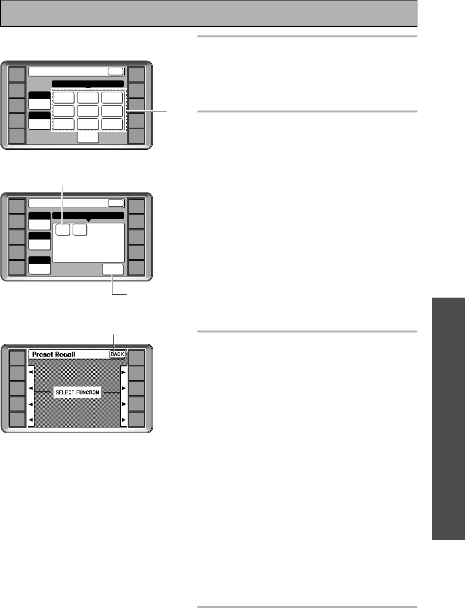
OPERATION
OPERATION
53
En
5
Select the name of the company
that makes your component.
If there are two pages of company names, use the
page +/– buttons to go back and forth between the
two sets of makers' names. For explanation purposes,
we'll use PIONEER as an example.
6
Press the NUMBER 1 button.
If the component you are trying to control turns on/
off, the set up for this component is complete, but
components that don't have a standby mode can't
respond in this way. To test if you've set it up properly
work through step 8. Then try using selecting the
function you just set up (for example a CD player) and
using the controls on this remote control. If the
component does not respond, try working through the
procedure again and pressing number 2 instead this
time. Continue this procedure until one of the com-
mands works.
If none of the commands seem to work, try the
learning mode to program the component into the
remote control. This is explained on the following
page.
To go back a screen
press the BACK button.
To exit the process without inputting the
commands
press the BACK button repeatedly.
7
Press the SETUP OK button and the
screen returns to SELECT
FUNCTION so you can program
another component into the remote
control.
Repeat the process for all of your components.
You may find you have components which do not
correspond to the name on any function button (for
example a cable TV tuner) or you have two
components where only one button is provided (MD/
TAPE 1). In this case, use step 3 to assign any
available function button to the component you want
to remote control.
For example, you may have a cable TV tuner and one
video deck in your system. It would make sense to
assign the VCR 2 function button to your cable TV
tuner in step 3. The rest of the procedure is the same
as before. Choose CATV in step 4. The only practical
difference in this method is that you have to
remember the VCR 2 function button is actually your
cable TV tuner.
In this case, you would need to hook up your cable TV
tuner to the input jacks marked VCR 2.
This method should help you customize the remote
control for your system.
8
Press the BACK button repeatedly
to leave the PRESET RECALL set up
mode.
Remote Control of Other Components
5
6
7
AMP
DVD/LD
TV/SAT
VCR1
VCR2
REMOTE
SETUP
MD/TAPE1
CD
LINE/
TUNER
TV
CONTROL
Preset Recall
[DVD/LD]
SETUP
OK
DVD
SELECT NUMBER
MAKER
ITEM
NUMBER
PIONEER
BACK
1
2
7 8
9
5
1
6
10 11 12
AMP
DVD/LD
TV/SAT
VCR1
VCR2
REMOTE
SETUP
MD/TAPE1
CD
LINE/
TUNER
TV
CONTROL
Preset Recall
PAGE
1 / 1
SAM-
SUNG
PIONEER
TOSHIBA
ITEM
SELECT MAKER
MAKER
SHARP
SONY PANA-
SONIC
DVD
PIONEER JVC AKAI
RCA
BACKDVD/LD][
«
BACK
DVD/LD
TV/SAT
VCR1
VCR2
REMOTE
SETUP
MD/TAPE1
CD
LINE/
TUNER
TV
CONTROL
AMP
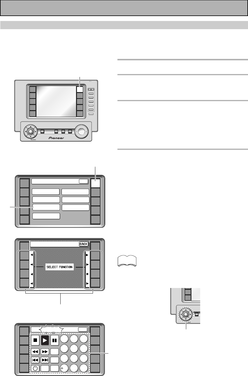
54
En
Learning Mode: Programming Signals from Other Remote Controls
If preset codes are not available for your component(s), or the available preset codes do not operate correctly,
you can use this procedure to program in signals from the remote control(s) of your other component(s). These
steps can also be used to add further operations to the remote control screens that were successfully set with
the stored settings (see p.52-53).
1
Press the REMOTE SETUP.
2
Press the LEARNING button.
If you want to cancel the REMOTE SETUP mode
press BACK. You will return to the amplifier menu.
3
SELECT FUNCTION blinks on the
remote control. Press the function
button for the component you want
to control.
For example purposes we will use the DVD/LD
function.
4
Choose the command you want to
teach the remote control and press
the corresponding button on the
LCD screen. The word “Learning”
will blink in the top bar of the
remote control screen.
For example, choose the 3 (play) button to program
this remote control to play your DVD player.
• The TV POWER, TV FUNC, TV CH +/– and VOL +/–
buttons are only available for learning when
programming TV CONTROL operations.
• Pressing BACK cancels the process.
You can also program the 5˜∞˜2˜3 and ENTER
cursor buttons with the LEARNING mode.
Remote Control of Other Components
ENTER
VCR1
VCR2
STANDBY/ON
BACK LIGHT
on/off
memo
5˜∞˜2˜3 and ENTER cursor buttons
2
AMP
DVD/LD
TV/SAT
VCR1
VCR2
REMOTE
SETUP
MD/TAPE1
CD
LINE/
TUNER
TV
CONTROL
KEY RENAME
ITEM MEMO
Remote Setup
LCD
COMMANDER
MULTI OPERATION
DIRECT FUNCTION
PRESET RECALL
LEARNING
BACK
1
4
AMP
DVD/LD
TV/SAT
VCR1
VCR2
REMOTE
SETUP
MD/TAPE1
CD
LINE/
TUNER
TV
CONTROL
DVD:Learning
12
4
789
56
3
SEARCH
MODE
TOP
MENU
SET UPMENU
BACK
0C
10
1
+
VOL
+
ENTER
AMP
DVD/LD
TV/SAT
VCR1
VCR2
REMOTE
SETUP
MD/TAPE1
CD
LINE/
TUNER
TV
CONTROL
FUNCTION
TV
CONTROL
MUTING
MASTER VOLUME
SYSTEM
OFF
MULTI
OPERATION
STANDBY/ON
–
VOL
–
CH
–
CH
+
FUNCTION
BACK LIGHT
use lock
on/off
3
DVD/LD
TV/SAT
VCR1
VCR2
REMOTE
SETUP
MD/TAPE1
CD
LINE/
TUNER
TV
CONTROL
AMP
Learning
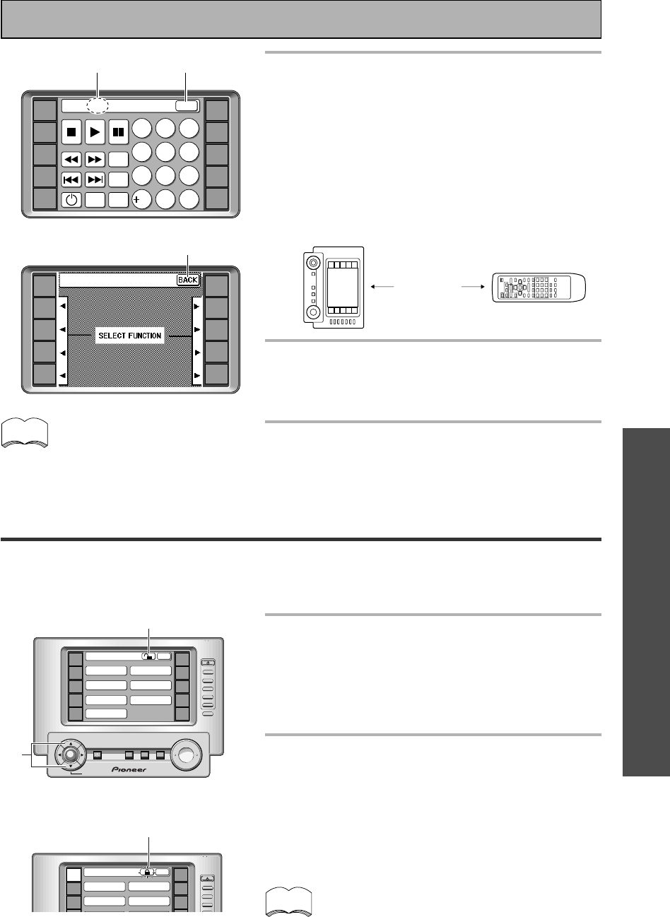
OPERATION
OPERATION
55
En
memo
Locking the Settings
This feature allows you to lock the SYSTEM SETUP and REMOTE SETUP settings so that they cannot be
changed without unlocking them first. When they are locked you cannot enter the setting screen in these
modes. The locking and unlocking procedures are done by the same process.
1
In the SYSTEM SETUP or REMOTE SET
UP screens hold down the 5˜∞
buttons at the same time. While you're
holding down the buttons a locked/
unlocked symbol will appear in the top
bar of the remote control.
2
Press the locked/unlocked symbol
while holding down the above two
keys. The setting will either lock or
unlock depending on the state it was
previously in.
From that time, if the screen is locked the lock symbol
will appear when that screen is accessed.
The only exception to LOCKING THE SETTINGS is the
LCD COMMANDER settings in the REMOTE SETUP
screen. They can still be accessed even when the
REMOTE SETUP screen is locked.
5
Point the two remote controls toward
each other. Press the button on the
other remote control corresponding to
the operation you want to program.
LEARNING flashes in the display on the VSA-E08 remote
control. After the process is complete and the command
has been learned, OK will appear at the top of the remote
control LCD display. If NG (no good) appears, it means
that for some reason the command was not learned.
Repeat steps 4 and 5 to teach the remote control of the
VSA-E08 all the commands from the other remote
control.
6
Press the BACK button to return to the
LEARNING/SELECT FUNCTION screen.
Start again from step 3 to program all your components in
this manner.
7
When you're done press the BACK
button repeatedly to return to the
REMOTE SETUP or AMPLIFIER menu.
memo
Some commands from other
remote controls cannot be
learned, but in most cases the
remotes just need to be moved
closer together or farther apart.
12-30 cm.
AMP
DVD/LD
TV/SAT
VCR1
VCR2
REMOTE
SETUP
MD/TAPE1
CD
LINE/
TUNER
TV
CONTROL
DVD:OK
12
4
789
56
3
SEARCH
MODE
TOP
MENU
SET UP
MENU
BACK
0C
10
6
5
7
DVD/LD
TV/SAT
VCR1
VCR2
REMOTE
SETUP
MD/TAPE1
CD
LINE/
TUNER
TV
CONTROL
AMP
Learning
Unlocked symbol
+
ENTER
AMP
DVD/LD
TV/SAT
VCR1
VCR2
REMOTE
SETUP
MD/TAPE1
CD
LINE/
TUNER
TV
CONTROL
MUTING
MASTER VOLUME
SYSTEM
OFF
MULTI
OPERATION
STANDBY/ON
—
CH
+
FUNCTION
TV
CONTROL
VOL
—
CH
—
VOL
+
FUNCTION
BACK LIGHT
use lock
on/off
Remote Setup
LCD
COMMANDER DIRECT FUNCTION
ITEM MEMO
KEY RENAME
PRESET RECALL
LEARNING
MULTI OPERATION
BACK
2
1
Remote Control of Other Components
AMP
DVD/LD
TV/SAT
REMOTE
SETUP
MD/TAPE1
CD
CH
+
FUNCTION
TV
CONTROL
CH
—
use lock
Remote Setup
LCD
COMMANDER
ITEM MEMO
DIRECT FUNCTION
PRESET RECALL
BACK
Locked symbol
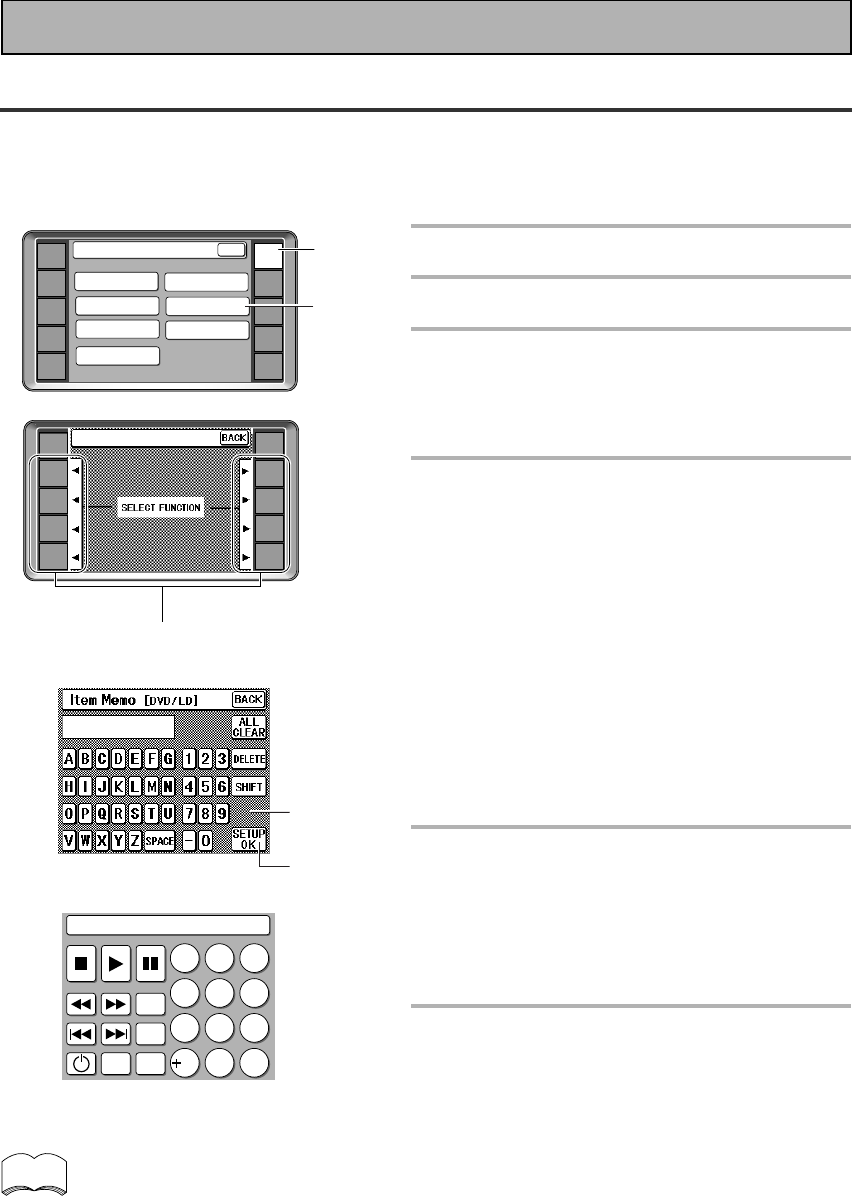
56
En
Item Memo
Use the ITEM MEMO capability to add more infomation to the remote control display screens for different
functions, like your DVD or CD player. For example, you could add the name of the company that makes your
component, then the top line of the screen for the respective component would read something like "DVD
PIONEER" .
1
Press the REMOTE SETUP.
2
Press the ITEM MEMO button.
3
Press the FUNCTION button of the
function/component you want to
additional information to, for
example, DVD.
4
Use the LETTER and the NUMBER
buttons to spell out the name you
want to add.
The keyboard works the same as a conventional
keyboard, if you press the SHIFT key the letters will
be lower case. Another press returns them to
capitals. You can include spaces and hyphens in the
name.
You can input up to ten letter/numbers.
The DELETE key clears the letters/numbers from the
right backwards.
The ALL CLEAR key erases everything that has been
typed.
5
Press the SETUP OK button when
the name appears in the bar as you
want it on the function screen.
The COMPLETE screen will show for half a second
to let you kow the name was successfully input.
The screen will then return to step two to allow you
to input names for other functions/components.
6
Use the BACK button to return to
the basic AMPLIFIER screen.
AMP
DVD/LD
TV/SAT
VCR1
VCR2
REMOTE
SETUP
MD/TAPE1
CD
LINE/
TUNER
TV
CONTROL
KEY RENAME
ITEM MEMO
Remote Setup
LCD
COMMANDER
MULTI OPERATION
DIRECT FUNCTION
PRESET RECALL
LEARNING
BACK
PIONEER
3
2
1
4
5
DVD/LD
TV/SAT
VCR1
VCR2
REMOTE
SETUP
MD/TAPE1
CD
LINE/
TUNER
TV
CONTROL
RECEIVER
Item Memo
memo
DVD
12
4
789
56
3
SEARCH
MODE
TOP
MENU
SET UP
MENU
0C
10
PIONEER
• You input up to ten letters or numbers. If you try to input more than ten the remote control will beep
twice to let you know this can't be done.
• You can include spaces and hyphens if you want.
• You can input this kind of information for up to eight functions/components.
• If you start this process but want to stop it without inputting the information entered press the BACK
key. This will return you to the previous screen without entering any of the information. You can use
this button to return to screen where you started.
Remote Control of Other Components
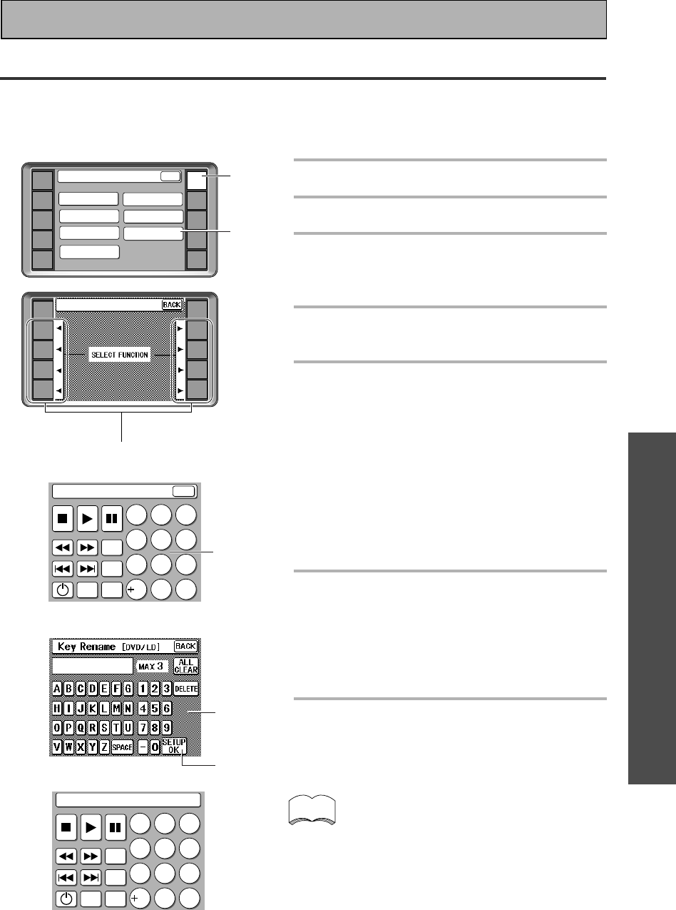
OPERATION
OPERATION
57
En
Remote Control of Other Components
memo
Key Rename
Use the KEY RENAME capability to rename the buttons (keys) on the remote control screens for different
functions (DVD, etc.). You would want to do this if you taught a specific button a new operation on the previous
two pages. For example, you could teach the SEARCH MODE button to be an audio key and the rename it
"AUD".
1
Press the REMOTE SETUP.
2
Press the KEY RENAME button.
3
Press the FUNCTION button that
has the has the button you want to
rename, for example, "DVD".
4
Press the LCD button (7, 3 etc) that
you want to rename.
5
Use the letter and number buttons
to spell out the name you want to
add.
The screen will tell you the maximum number of
letters/numbers you can input.
You can include spaces and hyphens in the name.
The DELETE key clears the letters/numbers from the
right backwards.
The ALL CLEAR key erases everything that has been
typed.
If you want to return to the previous name after
you've input a new one press either the ALL CLEAR
or DELETE buttons.
6
Press the SETUP OK button when
the name appears in the bar as you
want it on the function screen.
The COMPLETE screen will show for half a second
to let you know the name was successfully input.
The screen will then return to step four to allow you
to input names for other functions/components.
7
Use the BACK button to return to
the basic AMPLIFIER screen.
• If you try to input more letters/numbers than
possible the remote control will beep twice to
let you know this can't be done.
• You can include spaces and hyphens if you
want.
• If you start this process but want to stop it
without inputting the information entered use
the BACK key.
AMP
DVD/LD
TV/SAT
VCR1
VCR2
REMOTE
SETUP
MD/TAPE1
CD
LINE/
TUNER
TV
CONTROL
KEY RENAME
ITEM MEMO
Remote Setup
LCD
COMMANDER
MULTI OPERATION
DIRECT FUNCTION
PRESET RECALL
LEARNING
BACK
1
2
3
4
5
6
DVD/LD
TV/SAT
VCR1
VCR2
REMOTE
SETUP
MD/TAPE1
CD
LINE/
TUNER
TV
CONTROL
AMP
Key Rename
DVD : Key Rename
12
4
789
56
3
SEARCH
MODE
TOP
MENU
SET UP
MENU
0C
10
BACK
AUD
DVD
12
4
789
56
3
TOP
MENU
AUD
SET UP
MENU
0C
10
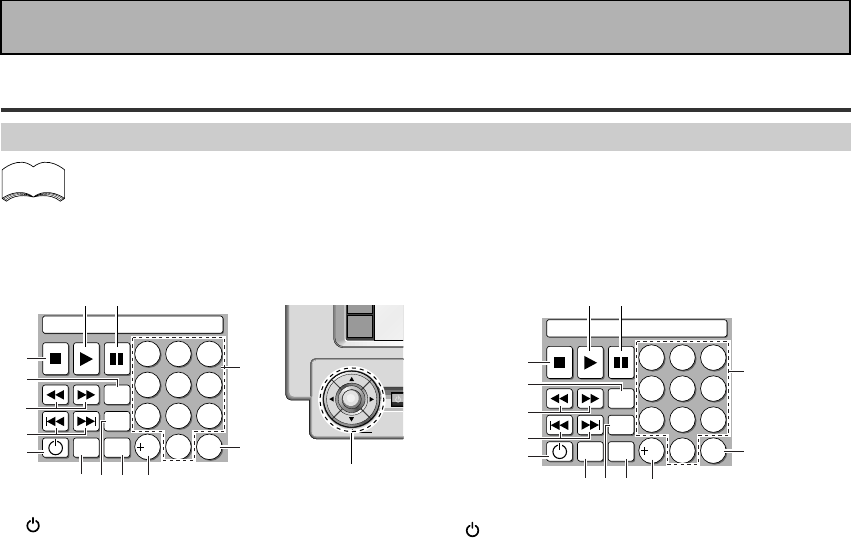
58
En
Using Remote Control with Other Components
DVD or LD player operations
•The following operations are available from the Amplifier’s remote control after you program
your DVD or LD player into it, but some operations may need to be learned separately by the
amplifier (see “Setting Up the Remote Control to Control Other Components,“ p.52-55).
• To perform these operations, press the DVD/LD button to set the remote to the DVD or LD operation
mode.
• For more information on individual commands consult the manual that came with the component.
Remote Control of Other Components
1
Press to switch the DVD player on or off (not
possible with all models, especially those without
a standby mode).
24˜¢
4 : Press to return to the beginning of the
current chapter (track). Press repeatedly to return
to the beginning of previous chapters (tracks).
¢ : Press to advance to the beginning of the
next chapter (track). Press repeatedly to advance
to the beginning of following chapters (tracks).
31˜¡
1 : Hold down for fast reverse playback.
¡ : Hold down for fast forward playback.
4SEARCH MODE
Press to perform a title, chapter/track or elapsed
time search.
57
Press to stop playback.
63
Press to start playback.
78
Press to pause playback.
8Number buttons
Use to select chapters (tracks).
9C
Use to clear chapters (tracks) or programmed
selections.
0+10
Use when selecting chapter (track) numbers
higher than 10.
-SET UP
Use to set the DVD player mode available on some
DVD players.
=TOP MENU
Press to call up the menu programed on the DVD.
~MENU
Use to display or close the title menu screen.
!5˜∞˜2˜3˜ENTER
5˜∞˜2˜3 : Use to navigate through options on
menu screens and to change settings.
ENTER : Use to implement settings selected with
the cursor buttons or to set items highlighted in a
menu.
1
Press to switch the LD player on or off (not
possible with all models, especially those without
a standby mode).
24˜¢
4 : Press to return to the beginning of the
current chapter (track). Press repeatedly to return
to the beginning of previous chapters (tracks).
¢ : Press to advance to the beginning of the
next chapter (track). Press repeatedly to advance
to the beginning of following chapters (tracks).
31˜¡
1 : Hold down for fast reverse playback.
¡ : Hold down for fast forward playback.
4AUDIO
The audio type can be changed betwen stereo and
mono setting and between digital and analog
setting.
57
Press to stop playback.
63
Press to start playback.
78
Press to pause playback.
8Number buttons
Use to select chapters (tracks).
9C
Use to clear chapters (tracks) or programmed
selections.
0+10
Use when selecting chapter (track) numbers
higher than 10.
-SIDE A/B
Use to change the LD between sides A and B.
=DISP
Use to view disc time, eleapsed time other
information programmed into certain discs.
~PRGM
Use to chapter (tracks) to program playback.
DVD
12
4
789
56
3
SEARCH
MODE
TOP
MENU
SET UP
MENU
0C
10
1
~=- 0
2
3
4
5
67
9
8
ENTER
VCR2
STANDB
Y/
BACK LIGH
T
on/off
LD
12
4
789
56
3
AUDIO
DISP
SIDE
A/B
PRGM
0C
10
1
~
=-
0
2
3
4
5
67
9
8
memo
!
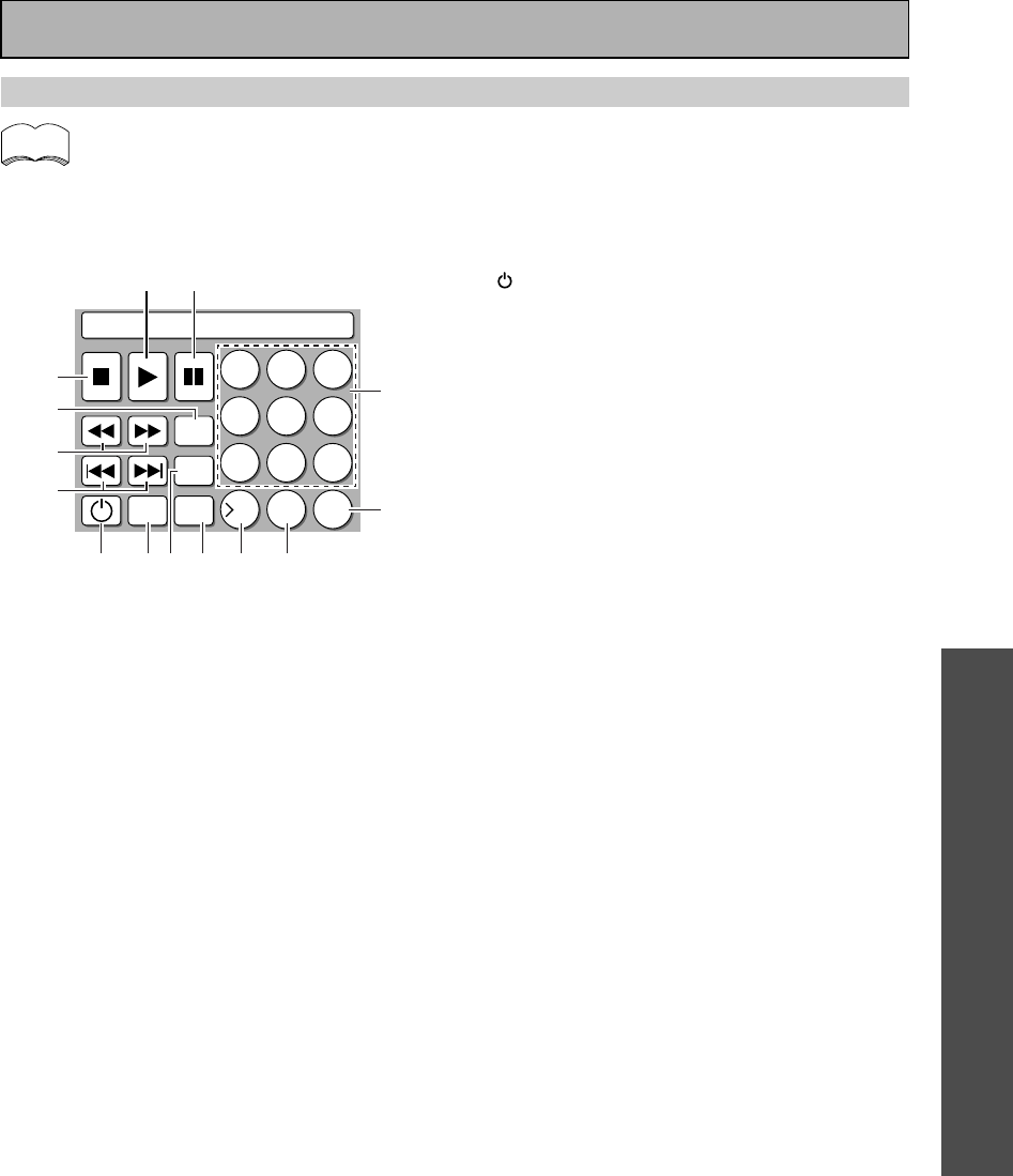
OPERATION
OPERATION
59
En
Remote Control of Other Components
CD player operations
•The following operations are available from the Amplifier’s remote control after you program
your CD player into it, but some operations may need to be learned separately by the amplifier
(see “Setting Up the Remote Control to Control Other Components,“ p.52-55).
• To perform these operations, press the CD button to set the remote to the CD operation mode.
• For more information on individual commands consult the manual that came with the component.
1
Press to switch the CD player on or off (not
possible with all models, especially those without
a standby mode).
24˜¢
4 : Press to return to the beginning of the
current track. Press repeatedly to return to the
beginning of previous tracks.
¢ : Press to advance to the beginning of the
next track. Press repeatedly to advance to the
beginning of following tracks.
31˜¡
1 : Hold down for fast reverse playback.
¡ : Hold down for fast forward playback.
4DISC
Use to switch between discs with file type disc
players.
57
Press to stop playback.
63
Press to start playback.
78
Press to pause playback.
8Number buttons
Use to select tracks.
9C
Use to clear tracks or programmed selections.
00/10
Use to select tracks with high numbers. The
button will increase the track number in
increments of ten.
->10
You can also use this button when selecting track
numbers higher than 10.
=RDM
Use to select the random playback function. The
CD player will play all the tracks on the disc in a
random order.
~Track
Use to select the track (not possible with all
models).
!PRGM
This button allows you to program a series of
tracks into the tracks into the CD player (may not
be possible with some CD players).
CD
12
4
789
56
3
DISC
RDM
TRACK
PRGM
C
10
0/10
0
1 !~ = -
2
3
4
5
6 7
9
8
memo
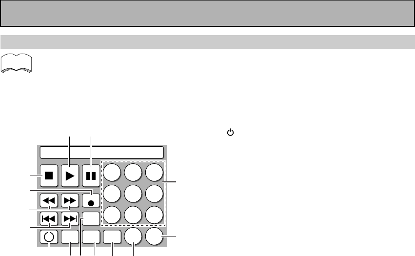
60
En
MD operations
•The following operations are available from the Amplifier’s remote control after you program
your MD recorder into it, but some operations may need to be learned separately by the ampli-
fier (see “Setting Up the Remote Control to Control Other Components,“ p.52-55).
• To perform these operations, press the MD/TAPE1 button to set the remote to the MD operation
mode.
• For more information on individual commands consult the manual that came with the component.
Remote Control of Other Components
1
Press to switch the MD recorder on or off (not
possible with all models, especially those without
a standby mode).
24˜¢
4 : Press to return to the beginning of the
current track. Press repeatedly to return to the
beginning of previous tracks.
¢ : Press to advance to the beginning of the
next track. Press repeatedly to advance to the
beginning of following tracks.
31˜¡
1 : Hold down for fast reverse playback.
¡ : Hold down for fast forward playback.
4¶ REC
Press to start recording (may put some decks in
REC PAUSE mode).
57
Press to stop playback or recording.
63
Press to start playback.
78
Press to pause playback or recording.
8Number buttons
Use to select tracks.
9 >10
You can also use this button when selecting track
numbers higher than 10.
00/10
Use to select tracks with high numbers. The
button will increase the track number in
increments of ten.
- NAME
Use to name tracks or programmed selections.
=EDIT MODE
Allows you to edit names and numbers of tracks.
~DISP
Allows you to change the display mode of the MD.
!ENTER
Enters the changes yo have made in the EDIT
MODE.
0/10
MD
12
4
789
56
3
REC
EDIT
MODE
NAME
ENTER
DISP
>10
0
1 !~ = -
2
3
4
5
6 7
9
8
memo
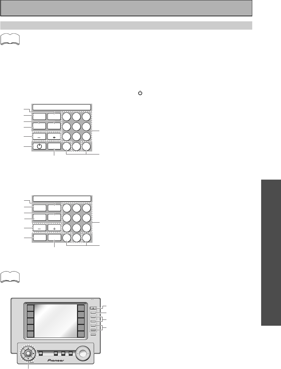
OPERATION
OPERATION
61
En
TV operations
•The following operations are available from the Amplifier’s remote control after you program
your TV into it, but some operations may need to be learned separately by the amplifier (see
“Setting Up the Remote Control to Control Other Components,“ p.52-55).
• To perform these operations, press the TV/SAT or TV CONTROL button to set the remote to the TV
operation mode.
• For more information on individual commands consult the manual that came with the your TV.
• The "Standard" screen will appear when presetting the TV/SAT (or any other) function button. When
presetting the TV CONTROL function button the "Digital" TV screen will appear.
memo
Remote Control of Other Components
1
Press to switch the TV on or off (not possible with
all models, especially those without a standby
mode).
2MENU
Use to select different menus on a TV screen.
3ANT
Use to select the type of antenna you have hooked
up to your TV.
4MUTE
Press to mute or restore the volume.
5VOL (–/+)
Press to control the volume of the TV.
6CH (–/+)
Use these buttons to change the channel of the
TV.
7Number buttons
Use to select a specific TV channel.
8SUB CH (–/+)
Use these buttons to change the sub-channel of
the TV.
9L1, L2
A freely assignable key where you can enter any
command you like—refer to p.54-55 for more on
this.
0TV FUNCTION
Press TV FUNCTION to select the TV's input.
-5/∞/2/3/ENTER
5/∞/2/3 : Use to select or adjust items on the
menu screen.
ENTER : Use to activate the selected function.
=P IN P
Press P IN P to turn on or off the sub-screen in
picture-in-picture mode.
~SWAP
Press SWAP to exchange the main screen for the
sub-screen.
!CHANNEL RETURN
Use to return to the previous channel.
TV
12
4
789
56
3
MUTE
0 L2L1
ANT
CH
SWAPPINP
MENU
CH
7
~
1
=
3
4
6
29
+
VOL
+
ENTER
AMP
DVD/LD
TV/SAT
VCR1
VCR2
REMOTE
SETUP
MD/TAPE1
CD
LINE/
TUNER
TV
CONTROL
FUNCTION
TV
CONTROL
MUTING
MASTER VOLUME
SYSTEM
OFF
MULTI
OPERATION
STANDBY/ON
–
VOL
–
CH
–
CH
+
FUNCTION
BACK LIGHT
use lock
on/off
-
0
1
6
5
Standard TV screen
TV screen (TV CONTROL)
You can operate your TV by using the TV
control buttons as well.
memo
TV
12
4
789
56
3
MUTE
0 L2L1
ANT
SUB CH
SWAPPINP
CHANNEL
RETURN
MENU
SUB CH
7
~
2
=
3
4
8
!9
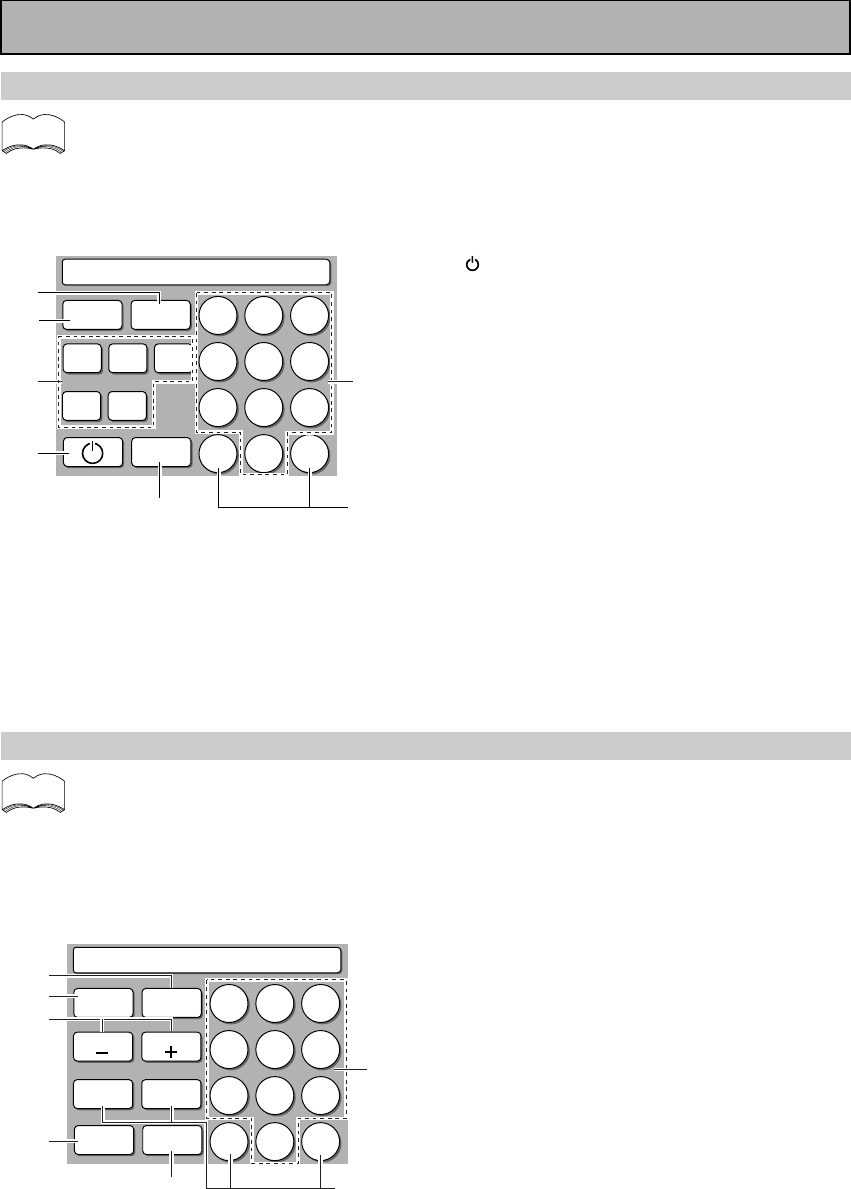
62
En
Remote Control of Other Components
STB (CATV) operations
•The following operations are available from the amplifier's remote control after you program
your CATV into it, but some operations may need to be learned separately by the amplifier (see
“Setting Up the Remote Control to Control Other Components,“ p.52-55).
• To perform these operations, press the TV CONTROL button to set the remote to the CATV opera-
tion mode.
• For more information on individual commands consult the manual that came with the your CATV.
1MUTE
Press to mute or restore the volume.
2PAGE (–/+)
Use to displays other pages of on-screen
information if there is too fit one screen.
3MENU
Use to display the main menu.
4GUIDE
Use to display the Program Guide screen.
5Number buttons
Use to select a specific TV channel.
6L1-4
Freely assignable keys where you can enter any
command you like-refer to p.54-55 for more on
this.
7CH ENTER
Use to select the channel specified with the
number buttons (not all models require this step).
memo
STB (CATV)
12
4
789
56
3
CH
ENTER
GUIDE
MUTE
MENU
0
PAGEPAGE
L1 L2
L3 L4
76
5
1
2
4
3
STB (satellite tuner) operations
•The following operations are available from the amplifier's remote control after you program
your satellite tuner into it, but some operations may need to be learned separately by the
amplifier (see “Setting Up the Remote Control to Control Other Components,“ p.52-55).
• To perform these operations, press the TV/SAT button to set the remote to the SAT operation mode.
• For more information on individual commands consult the manual that came with the component.
memo
STB (SAT)
12
4
789
56
3
EXIT
D E
0
L1
AB
C
L2
GUIDEMENU
2
4
7
1
3
6
5
1
Press to switch the digital tuner on or off (not
possible with all models, especially those without
a standby mode).
2A/B/C/D/E
Use to make selections from the SAT menu.
3MENU
Use to turn the main menu on or off.
4GUIDE
Use to turn the program information screen on or
off.
5Number buttons
Use to select satellite channels.
6L1-2
Freely assignable keys where you can enter any
command you like-refer to p.54-55 for more on
this.
7EXIT
Press to exit the current setting of the SAT.
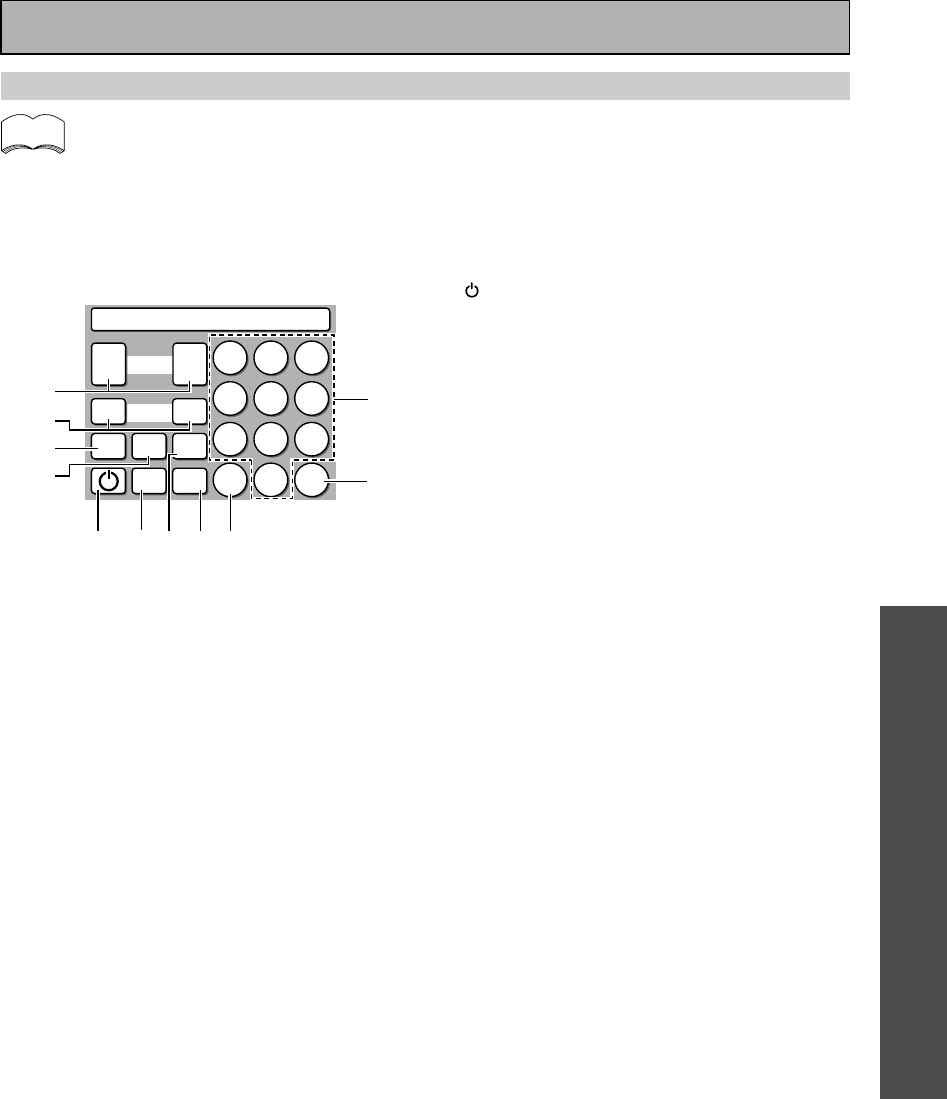
OPERATION
OPERATION
63
En
Remote Control of Other Components
Tuner
12
4
789
56
3
DIRECT
ACCESS
DISP
MODE RF
ATT
+
+
–
–
CLASS
BANDMPX
STATION
TUNING
0 L1
1
2
4
56
3
7
-890
memo
1
Press to switch the TUNER on or off (not possible
with all models, especially those without a
standby mode).
2BAND
Switches between AM and FM radio bands.
3MPX
Press to switch between auto stereo and mono
reception of FM broadcasts. When the broadcast
signal is weak, selecting mono will improve the
sound quality.
4TUNING –/+
Use to manually tune to radio stations.
5STATION –/+
Use to choose programmed radio stations.
6Number buttons
Use to input stations and frequency.
7L1
Use to program selections (not possible with all
models).
8DIRECT ACCESS
Allows you to input a frequency directly.
9CLASS
Use to select the class (A, B or C) that a preset
station is in.
0DISP MODE
Use this to switch between display modes.
-RF ATT
Press to turn the RF attenuator on when
receiving strong FM signals (nearby stations) to
reduce sound distortion.
Tuner operations
•The following operations are available from the amplifier's remote control after you program
your FM/AM tuner into it, but some operations may need to be learned separately by the
amplifier (see “Setting Up the Remote Control to Control Other Components,“ p.52-55).
• To perform these operations, press the LINE/TUNER button to set the remote to the CD operation
mode.
• For more information on individual commands consult the manual that came with the component.
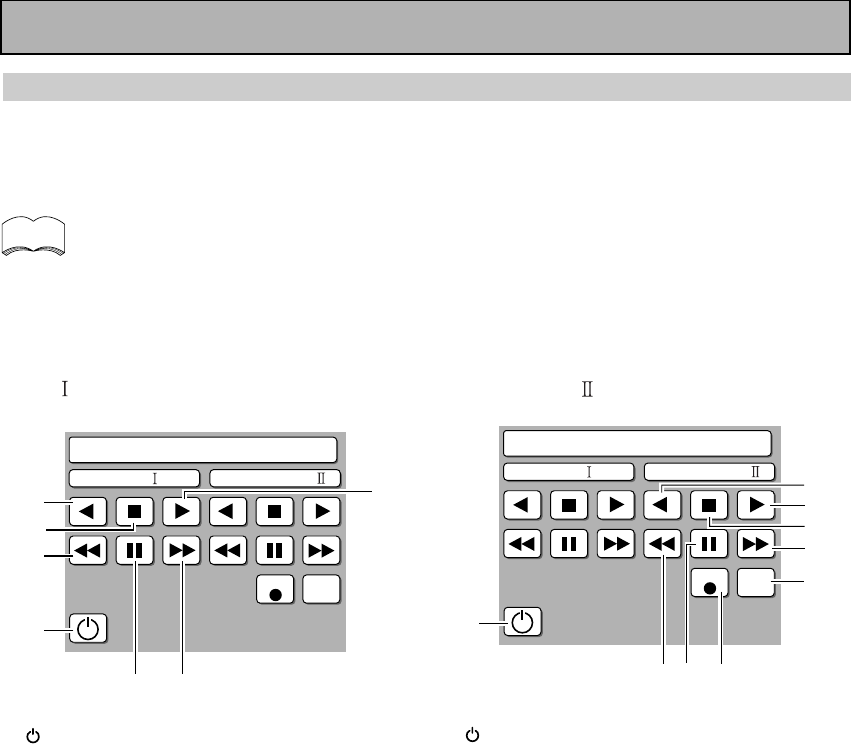
64
En
Cassette deck operations
You can use this remote control to control a single or a double cassette deck after you program the deck player
into it. If you have a regular cassette deck with only one set of tape heads use the buttons on the right marked
“SINGLE/DECK II“. If you have a double cassette deck with use the buttons on the left for deck I and the
buttons on the right for deck II.
•The following operations are available from the Amplifier’s remote control after you program
your Cassette deck into it, but some operations may need to be learned separately by the
amplifier (see “Setting Up the Remote Control to Control Other Components,“ p.52-55).
• To perform these operations, press the MD/TAPE1 button to set the remote to the TAPE operation
mode.
• For more information on individual commands consult the manual that came with the component.
DECK SINGLE/DECK
1
Press to switch the cassette deck on or off (not
possible with all models, especially those without
a standby mode).
21
Press to rewind the tape.
37
Press to stop playback or recording.
42
Press to start reverse playback (for auto reverse
decks).
53
Press to start playback of the side of the cassette
which has been loaded as the front.
6¡
Press to fast forward the tape.
78
Press to pause playback or recording.
1
Press to switch the cassette deck on or off (not
possible with all models, especially those without
a standby mode).
22
Press to start reverse playback (for auto reverse
decks).
33
Press to start playback of the side of the cassette
which has been loaded as the front.
47
Press to stop playback or recording.
5¡
Press to fast forward the tape.
6REC MUTE
Press and hold to make a blank space during
recording. The recording will be muted for as long
as the button is held down.
7REC 
Press to start recording (may put some decks in
REC PAUSE mode).
88
Press to pause playback or recording.
91
Press to rewind the tape.
memo
Tape
DECK
REC REC
MUTE
SINGLE / DECK
1
2
3
45
67
Tape
DECK
REC REC
MUTE
SINGLE / DECK
1
8
5
4
2
6
7
9
3
Remote Control of Other Components
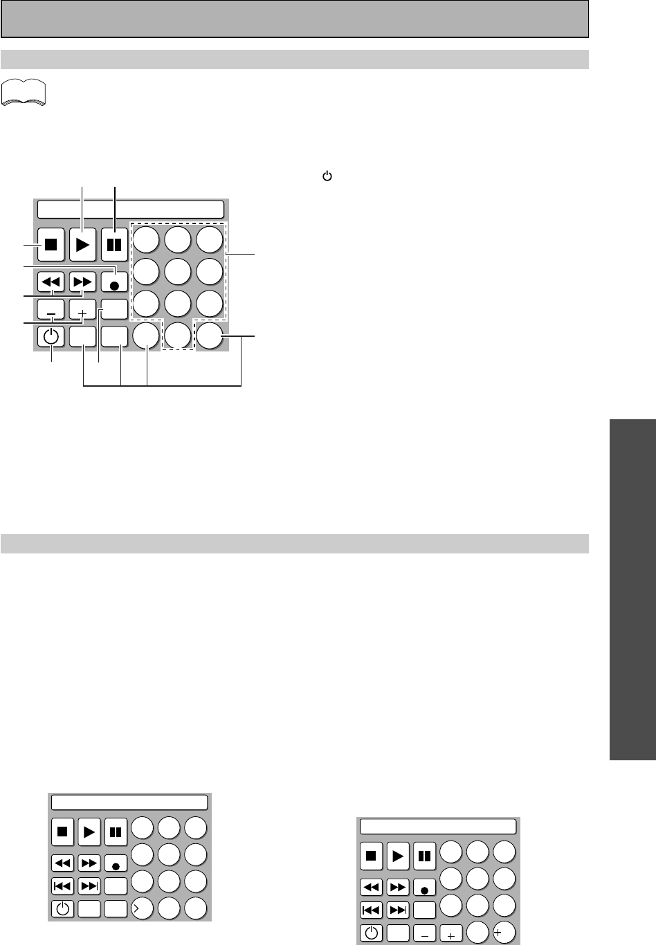
OPERATION
OPERATION
65
En
Remote Control of Other Components
VCR operations
•The following operations are available from the Amplifier’s remote control after you program
your VCR deck into it, but some operations may need to be learned separately by the amplifier
(see “Setting Up the Remote Control to Control Other Components,“ p.52-55).
• To perform these operations, press the VCR 1 or VCR 2 button to set the remote to the VCR operation
mode.
• For more information on individual commands consult the manual that came with the component.
1
Press to switch the VCR on or off(not possible
with all models, especially those without a standby
mode).
2CH –/+
Use to change channels on the VCR's tuner.
31˜¡
1 : Press to rewind the tape.
¡ : Press to fast foward the tape.
4 REC 
Press to start recording.
57
Press to stop playback.
63
Press to start playback.
78
Press to pause playback.
8Number buttons
Use to change channels on the VCR.
9L1-4
Freely assignable keys where you can enter any
commands you like-refer to p.54-55 for more on this.
0TV/VCR
Use this button to switch the VCR between it's TV
tuner and the video function.
Other screen for preset operations
In addition to the operations mentioned in this section up to this point, the VSA-E08 is equipped with remote
control screens to deal with a variety of cutting edge technologies and components that may or may not have
appeared on the market yet. These include: CD-R (CD write-once discs deck), CD-RW (CD rewritable discs
deck), and the latest innovation, DVD video recorder.
If you have one of these components you can access the preset screen by going to the preset recall section of
this manual (p.52-55) and following the instructions therein. Select the appropriate screen from the list
presented and assign it to a function button in the manner described. Then you can access the screen by simply
pressing that function button.
Below are a list of the screens of cutting edge components you can access.
CD-R operations
Essentially all the controls are the same as those
explaining the screen for a regular CD player with the
added feature of being able to record. The (¶ REC)
and the REC MUTE buttons are explained on
p.60
under the MD explanations.
memo
VCR
12
4
789
56
3
REC
CHCH TV/
VCR
L2
L1
L3 0 L4
10
2
3
4
5
67
9
8
CD-R
12
4
789
56
3
REC
REC
MUTE
RDM
PRGM
C
10 10
DVR
12
4
78
0
9
56
3
REC
MENU CHCH
REC
STOP
10
DVR (DVD Recorder) operations
Essentially all the controls are the same as those
explaining the screen for a regular DVD player with
the added feature of being able to record. The record
button (¶ REC) is explained on p.60 under the MD
explanations. REC STOP is a special DVD video
recorder control that stops the recording.
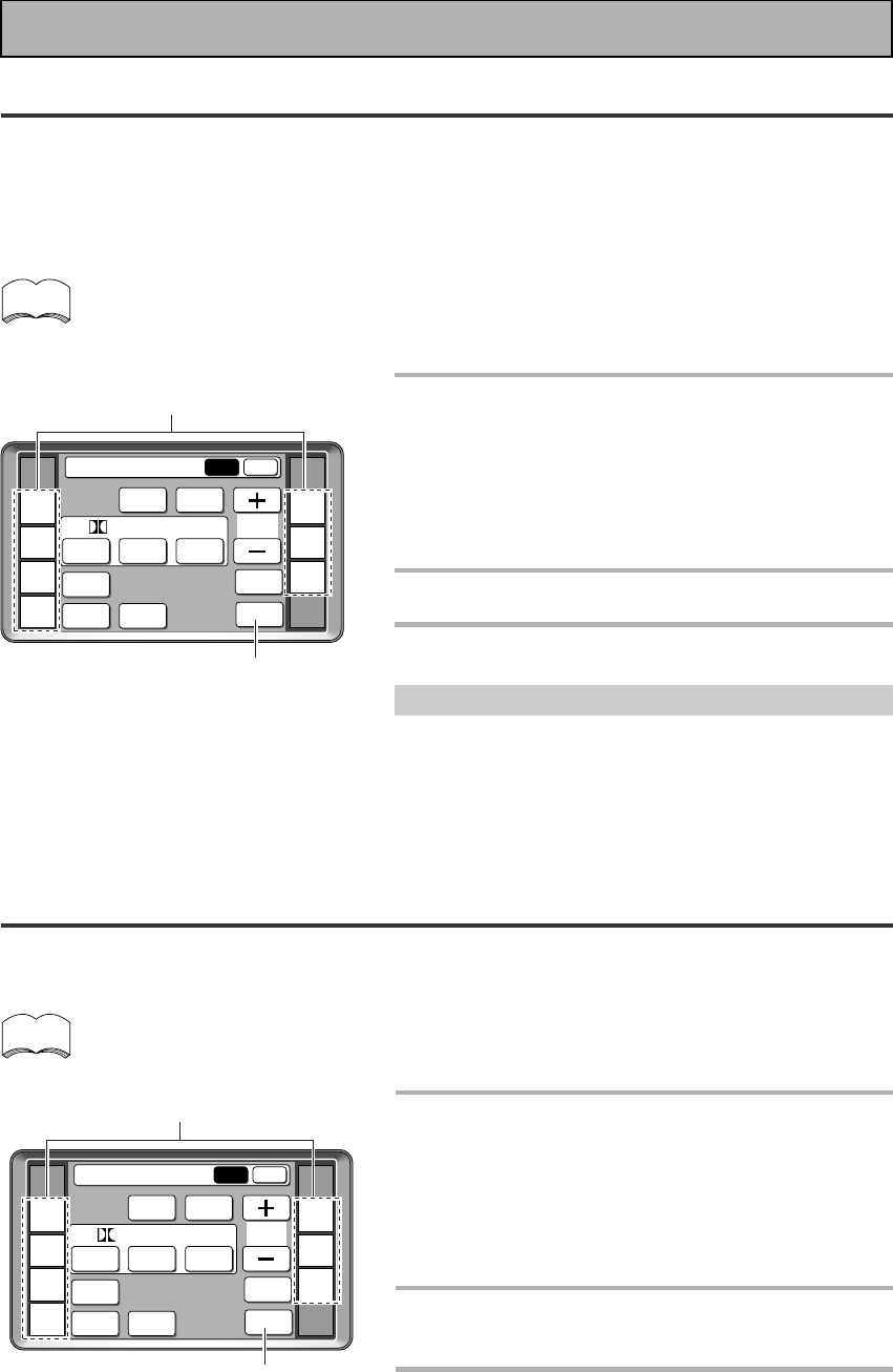
66
En
Recording from Audio Components
The following explanations show you how to record an analog or digital audio signal. Note that your analog
components cannot record a player that is only connected digitally (and vice-versa). If you want to record from a
digital component to an analog one (for example, a tape deck), or vice-versa, the digital component it must be
connected via analog jacks and you need to set the SIGNAL SELECT switch to ANALOG. To make exact digital
copies (of digital sources like CDs) both the source component and the recorder must be connected with digital
connections. See p.12 for more on analog audio connections and p.13 for digital audio connections.
The Amplifier’s volume, channel level, balance, TONE, DNR, MIDNIGHT, LOUDNESS and surround effects
have no effect on the recorded signal and the MULTI CH IN cannot be recorded.
In some cases, digital recordings have copy guard protections and making a digital copy is not possible.
In this case you can only copy them in an analog manner.
1
Select the source component. Set
SIGNAL SELECT according to the
source component's signal (ANALOG
or DIGITAL).
Press the SIGNAL SELECT button on the remote control
(or use the button on the front panel) and choose
ANALOG.
2
Start recording with a recorder.
3
Playback the source to be recorded.
Record monitor (TAPE 2 MONITOR)
If you connect a cassette deck with a record monitor function
to the TAPE 2 MONITOR jacks, you can listen to the sound of
an analog recording as it is being recorded.
Press TAPE 2 MONITOR to switch between the sound of the
recording (TAPE 2 indicator on) and the sound of the source
component (TAPE 2 indicator off).
Using Other Functions
Recording from Video Components
The following operations show you how to record audio and video to the video tape recorder connected to the
VCR 1/DVR or VCR 2 jacks. Note that all signals coming out of these jacks will be analog and it is not possible to
record Dolby Digital/DTS soundtracks.
The Amplifier’s volume, channel level, balance, TONE, DIGITAL NR, MIDNIGHT, LOUDNESS and surround
effects have no effect on the recorded signal.
1
First, decide the component you'd like
to record and put the amplifier in that
function. Set the SIGNAL SELECT to
analog.
Press the SIGNAL SELECT button on the remote control
(or use the button on the front panel) and choose analog.
Recording DIGITAL or 2 RF signals is not possible.
2
Start recording with VCR 1 or VCR 2
(etc.).
3
Playback the source to be recorded.
1
(if necessary)
Functions that can be recorded
1
(if necessary)
Functions that can be recorded
memo
memo
AMP
DVD/LD
TV/SAT
VCR1
VCR2
REMOTE
SETUP
MD/TAPE1
CD
LINE/
TUNER
TV
CONTROL
Receiver
MAIN SUB
DSP STEREO
THX
ADVANCED
THEATER
EFFECT
STANDARD
MIDNIGHT
LOUDNESS
DIRECT SIGNAL
SELECT
DIGITAL
NR
/ dts
MAIN SUB
DSP STEREO
THX
ADVANCED
THEATER
EFFECT
STANDARD
MIDNIGHT
LOUDNESS
SIGNAL
SELECT
DIGITAL
NR
/ dts
/ MPEG
MULTI CH
IN
Amplifier
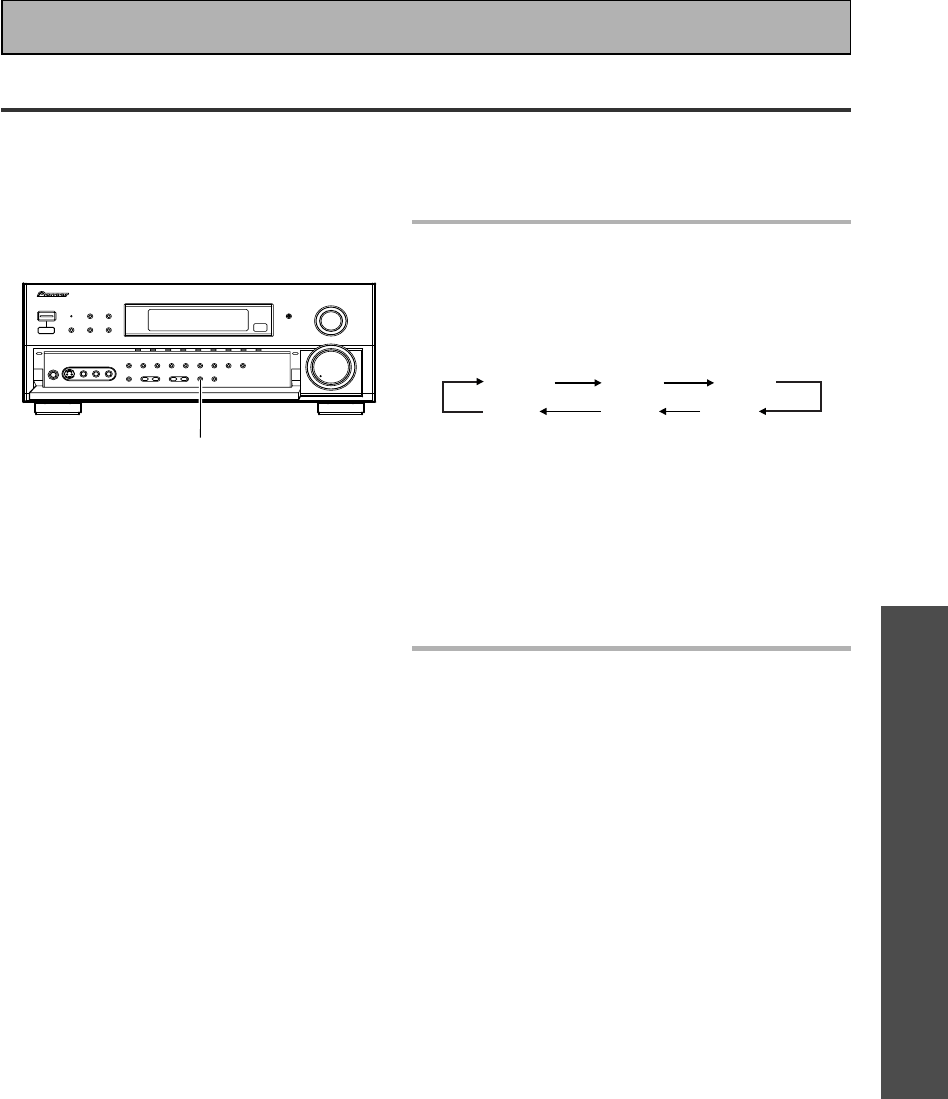
OPERATION
OPERATION
67
En
Video Select
Press the VIDEO SELECT button on
the front panel to cycle through the
different possible video inputs.
The first press shows the video input you are
currently using. After that pressing VIDEO SELECT
cycles though the possibilities in the following order:
DVD/LD VCR1 VCR2
(OFF) TV VIDEO
The OFF setting means the AUDIO and VIDEO
source are the same. (Also, if one of the MD/TAPE 1,
CD, LINE/TUNER, or PHONO functions are selected
the VIDEO SELECT will be set to OFF.)
After choosing a video input the display on the
amplifier will show that input for about 5 seconds
and then revert to showing the sound mode the
amplifier is in.
The VIDEO SELECT remains set to
the input you chose until you
change the audio input.
If you change audio functions the amplifier will reset
itself to make the video and audio inputs correspond.
Also, if you switch the power of the amplifier OFF
when you turn it back on the video and audio inputs
will reset so that they correspond.
This function allows you to listen to one sound source while you watch a different video source on your TV. The
sound source is set in the normal fashion as is explained on p.45. You then alter the video input with the VIDEO
SELECT button.
Using Other Functions
VIDEO SELECT button
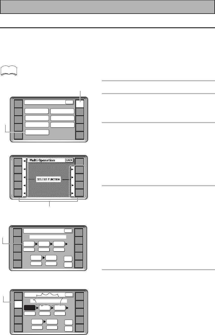
68
En
Multi Operations
Multi operations allow you to tell the amplifier and your other components to do a number of things with the
push of only two buttons on the LCD commander. For example, you can program the unit to turn on your TV,
turn on your DVD player and start playing the loaded DVD. This allows you to freely decide which operations you
want performed as well as the order in which you want them performed. The steps below show you how to
program a string of up to 5 different operations based on eight possible components. You don't need to program
the power of this unit to go on, it will do so automatically when multi operations are recalled.
Be sure to recall or learn the remote commands for each component before attempting multi
operations (see “Setting Up the Remote Control to Control Other Components“, p.52-55).
Using Other Functions
1
Press the REMOTE SETUP button.
2
Press the MULTI OPERATION
button.
To cancel MULTI OPERATION
Press REMOTE SETUP button again.
3
The next screen will instruct you to
SELECT FUNCTION. Choose the
component you want to start the
MULTI OPERATION with and press
it's FUNCTION button.
For example purposes we'll use a DVD player as the
first component to be set in this multi operation
process.
To go back to the REMOTE SETUP screen
Press the BACK button.
4
Next you should select the
command number you want the
process to start with. Of course it's
logical to start with 1 so press
command 1 (the box the 1 with
inside it).
This tells the amplifier this will be the first command.
To erase a command
Press the command button you want to erase and
press the CLEAR button.
To go back one step
Press the BACK button.
To go back to the REMOTE SETUP screen
Press the BACK button repeatedly.
5
Select the component whose
command you want to input (for
example, a DVD player), and press
that button on the remote control.
The LCD screen for that component
will appear on the remote control.
The screen for that component will appear in the LCD
display.
To go back one step
Press the BACK button.
To go back to the REMOTE SETUP screen
Press the BACK button repeatedly.
memo
3
DVD/LD
TV/SAT
VCR1
VCR2
REMOTE
SETUP
MD/TAPE1
CD
LINE/
TUNER
TV
CONTROL
AMP
2
1
AMP
DVD/LD
TV/SAT
VCR1
VCR2
REMOTE
SETUP
MD/TAPE1
CD
LINE/
TUNER
TV
CONTROL
KEY RENAME
ITEM MEMO
Remote Setup
LCD
COMMANDER
MULTI OPERATION
DIRECT FUNCTION
PRESET RECALL
LEARNING
BACK
AMP
DVD/LD
TV/SAT
VCR1
VCR2
REMOTE
SETUP
MD/TAPE1
CD
LINE/
TUNER
TV
CONTROL
Multi Operation
12
45
3
SETUP
OK
SELECT NUMBER
DVD/LD
[ ]
BACK
CLEAR
4
AMP
DVD/LD
TV/SAT
VCR1
VCR2
REMOTE
SETUP
MD/TAPE1
CD
LINE/
TUNER
TV
CONTROL
Multi Operation
12
45
3
CLEAR
BACK
SELECT FUNCTION
DVD/LD
[ ]
CLEAR
SETUP
OK
5
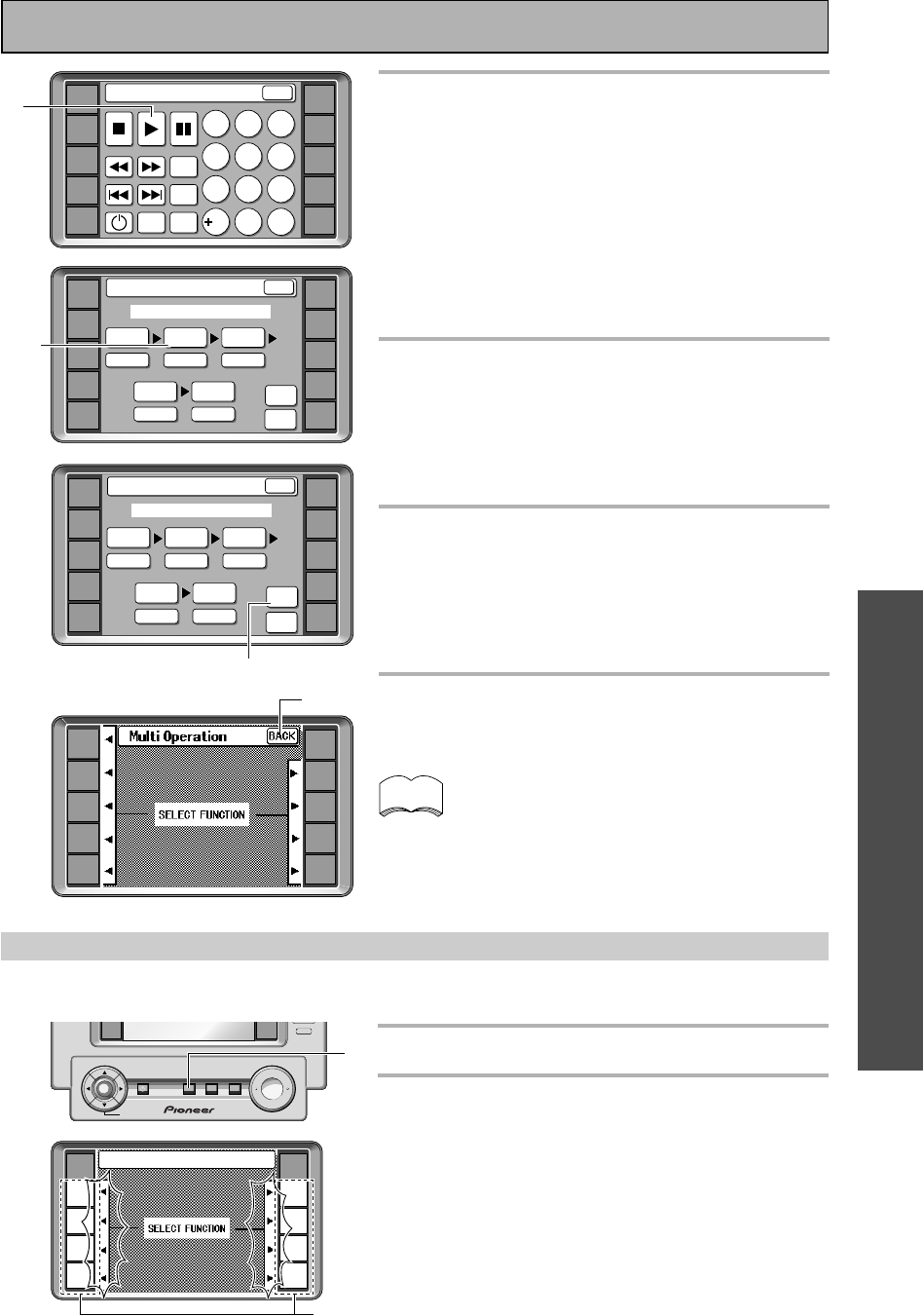
OPERATION
OPERATION
69
En
AMP
DVD/LD
TV/SAT
VCR1
VCR2
REMOTE
SETUP
MD/TAPE1
CD
LINE/
TUNER
TV
CONTROL
Multi Operation
3
2
45
3
DVD
BACK
SELECT NUMBER
DVD/LD
[ ]
CLEAR
CLEAR
SETUP
OK
6
Select a command from the screen
of the component (for example 3
[play]).
The command and component chosen will appear in the
window of command 1.
To erase a command
Press the command button you want to erase and press
the CLEAR button.
To go back one step
Press the BACK button.
To go back to the REMOTE SETUP screen
Press the BACK button repeatedly.
7
Repeat steps 4-6 to program a
sequence of up to five commands.
You can assign MULTI OPERATIONS for up to 5 function
buttons.
To erase a command
Press the command button you want to erase and press
the CLEAR button.
8
When done press SETUP OK to input
the information.
After you press SETUP OK the LCD screen on the
remote will flash COMPLETE to let you know the
process has been stored.
The remote then returns to the mode allowing you to
input more multi operations.
9
Press the BACK button repeatedly to
leave the multi operation set up
mode.
You don't need to program power on for PIONEER
components (except for the first generation of Pio-
neer DVRs), they will go on automatically if a
command for that unit is entered in the MULTI
OPERATIONS settings. Also, your TV will go on
automatically if a TV related command is entered in
the MULTI OPERATIONS.
Performing multi operations
Do the following to use the MULTI OPERATIONS.
1
Press the MULTI OPERATION button.
2
Press the function button that has
been set up with multi operations.
The power of the main unit goes on and the
programmed multi operations are performed
automatically.
2
1
+
ENTER
VCR2
TV
CONTROL
MUTING
MASTER VOLUME
SYSTEM
OFF
MULTI
OPERATION
STANDBY/ON
–
FUNCTION
BACK LIGHT
on/off
memo
6
AMP
DVD/LD
TV/SAT
VCR1
VCR2
REMOTE
SETUP
MD/TAPE1
CD
LINE/
TUNER
TV
CONTROL
Multi Operation
32
45
3
DVD
BACK
SELECT NUMBER
DVD/LD
[ ]
CLEAR
CLEAR
SETUP
OK
8
7
AMP
DVD/LD
TV/SAT
VCR1
VCR2
REMOTE
SETUP
MD/TAPE1
CD
LINE/
TUNER
TV
CONTROL
DVD:Multi Operation
12
4
789
56
3
SEARCH
MODE
TOP
MENU
SETUP
MENU
BACK
0C
10
DVD/LD
TV/SAT
VCR1
VCR2
REMOTE
SETUP
MD/TAPE1
CD
LINE/
TUNER
TV
CONTROL
AMP
9
RECEIVER
DVD/LD
TV/SAT
VCR1
VCR2
REMOTE
SETUP
MD/TAPE1
CD
TUNER
TV
CONTROL
Multi Operation
Using Other Functions
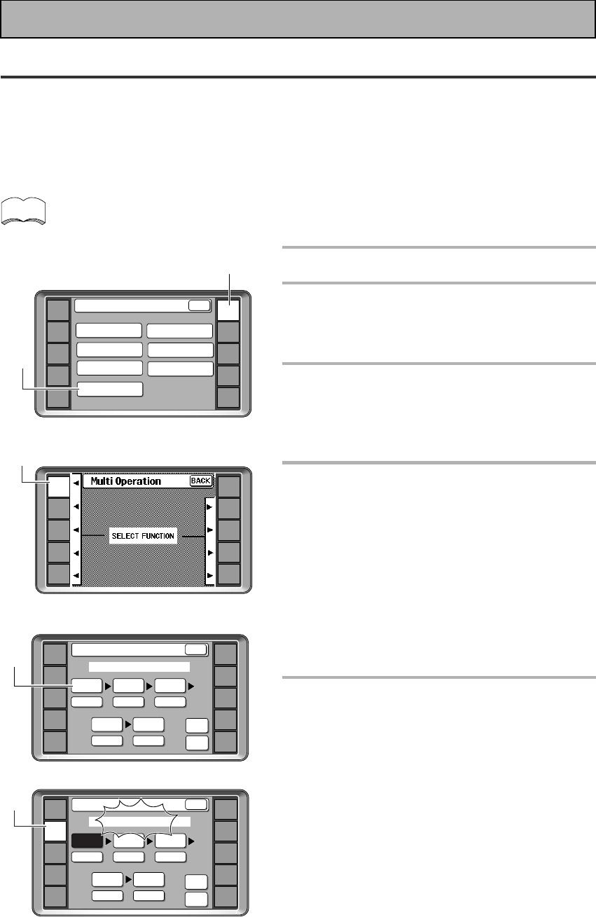
70
En
System OFF
The SYSTEM OFF feature allows you to tell the receiver and your other components to stop and turn off with
the push of only one button on the LCD commander (this feature will only work with components that have a
standby mode). For example, you can program the unit to stop your DVD, turn off your TV, turn off your DVD
player and turn off the receiver itself. You don't need to program in other the power for PIONEER components,
they will go off automatically in this mode. The receiver itself will go off automatically as well.
The steps below show you how to program a string of up to 5 different SYSTEM OFF operations based on eight
possible components.
Be sure to recall or learn the remote commands for each component before programming the
SYSTEM OFF function (see “Setting Up the Remote Control to Control Other Components“, p.
52-55).
1
Press the REMOTE SETUP button.
2
Press the MULTI OPERATION
button.
To cancel MULTI OPERATION
Press REMOTE SETUP button again.
3
The next screen will instruct you to
SELECT FUNCTION. Press the
AMPLIFIER button.
To go back to the REMOTE SETUP screen
Press the BACK button.
4
Next you should select the
command number you want the
process to start with. Of course it's
logical to start with 1 so press
command 1 button (the box the 1
with inside it).
This tells the amplifier this will be the first command.
The number will become shaded.
To go back one step
Press the BACK button.
To go back to the REMOTE SETUP screen
Press the BACK button repeatedly.
5
Select the FUNCTION button of the
component which you want to stop
or turn off (for example, stop your
DVD player) and press that
FUNCTION button on the remote
control.
The screen for that component will appear in the LCD
display.
To go back one step
Press the BACK button.
To go back to the REMOTE SETUP screen
Press the BACK button repeatedly.
memo
2
1
AMP
DVD/LD
TV/SAT
VCR1
VCR2
REMOTE
SETUP
MD/TAPE1
CD
LINE/
TUNER
TV
CONTROL
KEY RENAME
ITEM MEMO
Remote Setup
LCD
COMMANDER
MULTI OPERATION
DIRECT FUNCTION
PRESET RECALL
LEARNING
BACK
3
AMP
DVD/LD
TV/SAT
VCR1
VCR2
REMOTE
SETUP
MD/TAPE1
CD
LINE/
TUNER
TV
CONTROL
5
AMP
DVD/LD
TV/SAT
VCR1
VCR2
REMOTE
SETUP
MD/TAPE1
CD
LINE/
TUNER
TV
CONTROL
SETUP
OK
System OFF
12
45
3
CLEAR
BACK
SELECT FUNCTION
AMP
DVD/LD
TV/SAT
VCR1
VCR2
REMOTE
SETUP
MD/TAPE1
CD
LINE/
TUNER
TV
CONTROL
System OFF
12
45
3
BACK
SELECT NUMBER
SETUP
OK
CLEAR
4
Using Other Functions
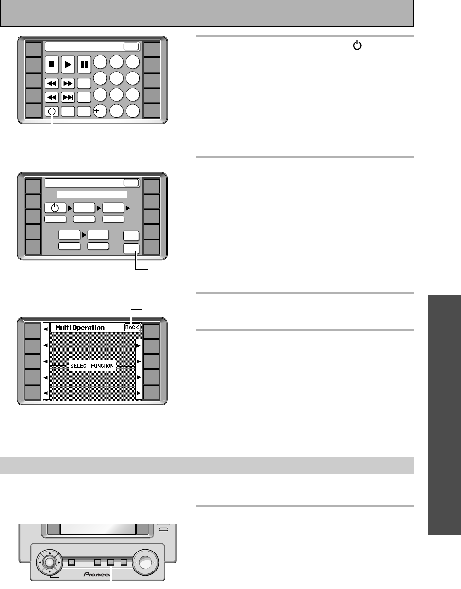
OPERATION
OPERATION
71
En
6
Select a stop or a power ( )
command.
The command and component chosen will appear in
the window of command 1.
To erase a command
Press the command button you want to erase and
press the CLEAR button.
To go back one step
Press the BACK button.
To go back to the REMOTE SETUP screen
Press the BACK button repeatedly.
7
Repeat steps 4-6 to program a
sequence of up to five stop or
power off commands you want to
input.
To erase a command
Press the command button you want to erase and
press the CLEAR button.
To go back one step
Press the BACK button.
To go back to the REMOTE SETUP screen
Press the BACK button repeatedly.
8
When done press SETUP OK to
input the information.
9
Press the BACK button repeatedly
to leave the multi operation set up
mode.
Using SYSTEM OFF
Do the following to use the SYSTEM OFF function.
1
Press the SYSTEM OFF button.
The remote control must be on to be able to use this
command but it can be in any mode.
All the components programmed into the SYSYTEM
OFF mode will stop and/or go off. The amplifier will go
off as well.
1
+
ENTER
VCR2
TV
CONTROL
MUTING
MASTER VOLUME
SYSTEM
OFF
MULTI
OPERATION
STANDBY/ON
–
FUNCTION
BACK LIGHT
on/off
AMP
DVD/LD
TV/SAT
VCR1
VCR2
REMOTE
SETUP
MD/TAPE1
CD
LINE/
TUNER
TV
CONTROL
DVD:System Off
12
4
789
56
3
SEARCH
MODE
TOP
MENU
SET UP
MENU
BACK
0C
10
«
6
AMP
DVD/LD
TV/SAT
VCR1
VCR2
REMOTE
SETUP
MD/TAPE1
CD
LINE/
TUNER
TV
CONTROL
SETUP
OK
System OFF
2
45
3
DVD
CLEAR
BACK
SELECT FUNCTION
8
DVD/LD
TV/SAT
VCR1
VCR2
REMOTE
SETUP
MD/TAPE1
CD
LINE/
TUNER
TV
CONTROL
AMP
9
Using Other Functions
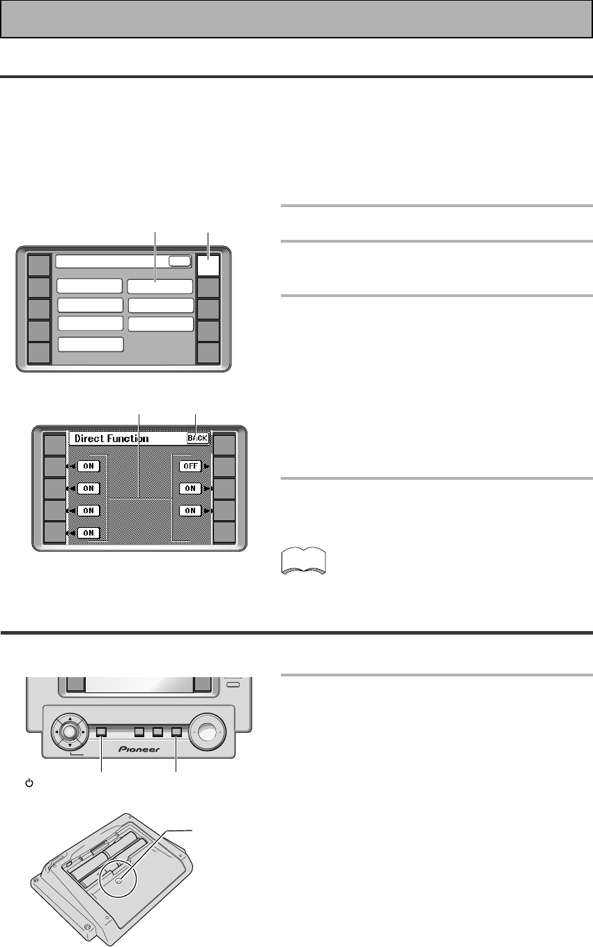
72
En
Setting up the DIRECT FUNCTION
The direct function will not be necessary for most users. It is designed in case you have an external video
source connected to your TV (a video source that is not going through the VSA-E08). For this explanation we'll
call this the "external video deck." You'd like to control external video deck with this unit's remote control so
you've assigned it a function button (for example purposes, the VCR 2 button). Yet, if you put the amplifier in
VCR 2 mode you'll get no picture on your TV because the external video deck signal is not going through the
VSA-E08. To get around this problem you set the DIRECT FUNCTION for VCR 2 to OFF. Now when you press
VCR 2 function button you can control the external video deck with the remote but the amplifier does not go into
VCR 2 mode.
1
Press the REMOTE SETUP.
2
Press the DIRECT FUNCTION
button.
3
Choose to set the DIRECT
FUNCTION of each source to ON or
OFF by pressing on the ON/OFF
button.
A triangular arrow points from the ON/OFF button
towards a small nub next to the function names (DVD/
LD, CD, etc.) that can be turned ON/OFF. This nub will
disappear if that DIRECT FUNCTION is turned OFF.
Subsequently the nub will not appear on any remote
control screen if the DIRECT FUNCTION is OFF.
4
To leave the Direct Function mode
press the BACK button.
The default setting for all DIRECT FUNCTIONS is
ON.
Resetting the Remote Control
The following operations allow you to erase the settings stored in the remote control.
Hold down both the STANDBY/ON
button and MUTING button and
then push the RESET tab under the
battery cover on the back of the
remote control.
memo
1
2
AMP
DVD/LD
TV/SAT
VCR1
VCR2
REMOTE
SETUP
MD/TAPE1
CD
LINE/
TUNER
TV
CONTROL
4
3
MUTING STANDBY/ON
+
ENTER
VCR2
TV
CONTROL
MUTING
MASTER VOLUME
SYSTEM
OFF
MULTI
OPERATION
STANDBY/ON
–
FUNCTION
BACK LIGHT
on/off
RESET tab
AMP
DVD/LD
TV/SAT
VCR1
VCR2
REMOTE
SETUP
MD/TAPE1
CD
LINE/
TUNER
TV
CONTROL
KEY RENAME
ITEM MEMO
Remote Setup
LCD
COMMANDER
MULTI OPERATION
DIRECT FUNCTION
PRESET RECALL
LEARNING
BACK
Using Other Functions
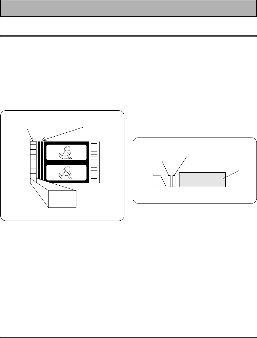
73
En
Techno Tidbits & Problem-solving
Dolby Digital
Digital
sound
2468101214 MHz
Frequency
Analog
sound
(Monaural)
Video
Dolby Digital
sound
Dolby Digital is a compression format which records
the sound of 6 or 8 channels of the theater surround
system (Dolby Digital) on the movie film digital track.
Of the 6-8 channels, the sub woofer channel is
intended for bass only, and because the frequency
range is smaller than a main channel, the overall
soundtrack is expressed as 5.1 or 7.1 channels.
Dolby Digital is the name of the Dolby surround multi-
channel digital system that was developed after the
Dolby Surround System and Dolby Pro Logic Surround
System.
The number of movies made using Dolby Digital since
1992 has exceeded 300 and continues to increase.
For compact disc players and laser disc digital sounds,
16 bits are used to sample the original analog audio
waveform and sampling is carried out 44,100 times
every second. However because an enormous
amount of recording signal data is required for the
multi channel system with this method, Dolby Digital
is used to compress the data.
In reproducing audio signals, the smaller the bit
number used, the lower the sound quality. With Dolby
Digital, drop in auditory sound quality is prevented by
using masking technology and digital filtering
technology based on the human auditory
characteristics.
Laser disc format
Laser discs are now available on the market in large
numbers. This means that the recording of different
format audio signals on the laser disc raises the
important question of compatibility with existing laser
discs. Dolby Digital tracks on laser discs record signals
using the space of one analog audio channel so it will
maintain compatibility with existing discs and players.
As shown in the following figure, the digital audio
sounds of Dolby Digital discs can be played back as
currently done. Analog sounds are played back by
using the other channel without the Dolby Digital
signals for monaural audio signals.
Comparison with Dolby Pro Logic
Surround
Dolby Digital is also known as the 5.1 channel system.
It is equipped with 5 channels (front left, front right,
center, surround left, surround right) in the frequency
range from 20 Hz to 20 kHz and an independent Low
Frequency Effect (LFE) channel. The sub woofer
channel is also called Low Frequency Effect (LFE).
The subwoofer channel can be used as desired to
enjoy strong bass sounds.
5.1 channel digital
surround track
4 channel analog sound
track (Matrix)
Dolby
Digital
encoding
Dolby Digital for movie films
MPEG Audio
MPEG is an audio encoding system which delivers high quality audio for music and movies. By removing
frequencies which are out of the human hearing range, the sound is then compressed to enable the
transmission of mono, stereo, or multichannel (5.1 and 7.1) audio in a single bitstream which is why it has
become a standard audio format for DVD and personal computers. The composition and versatility of MPEG
audio also ensures that the presentation of a multichannel soundtrack will sound appropriate on everything from
a 7.1 channel surround sound home theater setup to a mono television set. Above all, MPEG audio is designed
to be compatible with past and future MPEG audio versions, which means that future versions of MPEG audio
will be compatible with decoders currently being produced (the signal is merely reconfigured to fit the number of
channels available in a system).
1
74
En
Techno Tidbits & Problem-solving
DTS
DTS has been adopted as a sound recording format in the latest movie theaters since the release of “JURASSIC
PARK” in 1993, and has a good reputation for high quality sound and dynamic surround effects.
In this system, 6 channels of digital sound are recorded on CD-ROM, rather than on the film. DTS adopts a
simultaneous playback format. With a low rate of compression of sound signals and a high rate of transmittance,
a higher sound quality format is produced. Also, unlike the process of recording digital sounds on film directly,
the only components required are a CD-ROM player as might be used with a personal computer and a DTS
processor, and therefore less investment is required than with other formats. For this reason, the format is
being introduced in more and more movie theaters, and is being adopted in home movie software (DVD, LD)
and music software (5.1 channel CD). DTS has recently added a third surround channel to its system. This has
come to be known as DTS Extended Surround or simply DTS-ES.
THX
THX is a Lucasfilm, Ltd. program dedicated to maximum accuracy in movie presentation. Movie sound tracks are
recorded in large movie dubbing stages using movie theater equipment. For a sound track to be presented
accurately in your home, special technologies are required. In your home the room is much smaller and has a
bright sound, the speakers are very different and there are only six-eight of them, plus, you sit much closer to
each one of those speakers. Because of these differences we often miss the power and emotion that thrills us
in a good movie. Now Pioneer and THX have teamed up to bring the full glory of accurate cinema sound to the
comfort and convenience of your home.
Re-Equalization™ : In a theater the room is very large and dead sounding, you sit a long way back from the
speakers and the speakers themselves are very specialized. Because a sound track recorded in this dead
sounding space when it is played at home it sounds overbright. THX Re-Equalization adjusts for this difference in
a very precise way.
Adaptive Decorrelation™ : When a sound track sends mono sound to the surround speakers it often seems
to be coming come from one side instead of from all around you as it would in a theater. Adaptive Decorrelation
helps to correct this inaccuracy.
Timbre Matching™ : When recording a sound track it is very important that the surround sounds move
smoothly and seamlessly around the theater. It is very distracting when sounds seem to jump from speaker to
speaker. Timbre Matching helps to smooth the movement of the surround sounds even though you are using
only two speakers.
Bass Peak Level Manager™ : Some Dolby Digital sound tracks can produce bass peaks that are undesirable in
a home theater environment. The Bass Peak Level Manager allows you to set the maximum peak levels
appropriate to your system. (Set this function according to the BASS PEAK LEVEL MANAGER instructions on
page 38.)
Loudspeaker Position Time Synchronization™ : This feature allows you to adjust for the difference in the
distance from each individual loudspeaker to the listening position. Doing this ensures that all the speakers
operate in precise synchronization improving the seamless nature of the soundfield. (Set this function according
to the CHANNEL DELAY instructions on p.34.)
THX Surround EX™ : THX Surround EX–Dolby Digital Surround EX is a joint development of Dolby Laboratories
and the THX division of Lucasfilm Ltd.
In a movie theater, film soundtracks that have been encoded with Dolby Digital Surround EX technology are able
to reproduce an extra channel which has been added during the mixing of the program. This channel, called
Surround Back, places sounds behind the listener in addition to the currently available front left, front center,
front right, surround right, surround left and subwoofer channels. This additional channel provides the
opportunity for more detailed imaging behind the listener and brings more depth, spacious ambience and sound
localization than ever before.
Movies that were created using the Dolby Digital Surround EX technology, when released into the home
consumer market may exhibit a Dolby Digital Surround EX logo on the packaging. A list of movies created using
this technology can be found on the Dolby web site at http://www.dolby.com.
Only receiver and controller products bearing the THX Surround EX logo, when in the THX Surround EX mode,
faithfully reproduce this new technology in the home.
This product may also engage the "THX Surround EX" mode during the playback of 5.1 channel material that is
not
Dolby Digital Surround EX encoded. In such case the information delivered to the Surround Back channel will
be program dependent and may or may not be very pleasing depending on the particular soundtrack and the
tastes of the individual listener.
R

75
En
Techno Tidbits & Problem-solving
Troubleshooting
Incorrect operations are often mistaken for trouble and malfunctions. If you think that there is something wrong with
this component, check the points below. Sometimes the trouble may lie in another component. Investigate the other
components and electrical appliances being used. If the trouble cannot be rectified even after exercising the checks
listed below, ask your nearest PIONEER authorized service center or your dealer to carry out repair work.
Cause
• The power plug is disconnected.
• The protection circuit may have
been activated.
• Static electricity caused by dry air.
• Improper connections.
• Sound is muted.
• The volume is turned down.
• The TAPE 2 MONITOR is ON.
• Speakers are turned OFF.
• DIGITAL/ANALOG switch is set
incorrectly.
• Improper connections.
• The input source is not properly
selected.
• Settings route signal away from
subwoofer
• The LD is not a Dolby Digital
compatible disc.
• The Dolby Digital/DTS/MPEG source
is not 5 channels.
• Either the digital connections or the
DIGITAL INPUT SELECT is
incorrect.
• The TAPE2 MONITOR mode is ON.
• You are not using a source with
Surround EX flag.
• The player is paused or stopped.
• There is a mistake in the player
settings for audio output.
• Although it's a Dolby Digital / DTS /
MPEG source there is a possibility
the present trrack is not Dolby
Digital / DTS / MPEG.
Symptom
The power does not turn ON.
The unit does not respond when
the buttons are pressed.
No sound is output when a
function is selected.
No image is output when a
function is selected.
Subwoofer output is very low.
When playing an LD the SIGNAL
SELECT is on AC -3 RF but there
is still no sound.
When playing a Dolby Digital/DTS/
MPEG source the 5.1 Channel
indicator doesn't light.
You can't get DIGITAL to come up
when using the SIGNAL SELECT
button.
When using THX AUTO mode the
receiver is not playing in the EX
mode.
The Dolby Digital / DTS / MPEG
indicator doesn't light up even
when playing a Dolby Digital / DTS
/ MPEG source.
Remedy
• Connect the power plug to the wall
outlet.
• Disconnect the power plug from the
outlet, and insert again.
• Disconnect the power plug from the
outlet, and insert again.
• Make sure the component is
connected correctly (see p.12-20).
• Press MUTE on the remote control.
• Adjust MASTER VOLUME.
• Press the TAPE 2 MONITOR button.
• Press SPEAKERS (A/B) to select the
speakers you connected.
• Set SIGNAL SELECT (see p.47).
• Make sure the component is
connected correctly (see p.12-20).
• Press the correct function button.
• To get more signal to the subwoofer
set it to PLUS or choose SMALL for
the FRONT speakers (see p.32-33).
• Set the SIGNAL SELECT to analog
(make sure your LD player is hooked
up with analog connections in addition
to digital and 2 RF connections, see
p.14).
• There is no problem with the receiver
but if you want 5 channel sound you
must play a 5 channel source.
• Make sure the digital connections and
the DIGITAL INPUT SELECT is doner
correctly.
• Press the TAPE2 MONITOR button so
it goes inot the OFF setting.
• There is no problem with your
receiver but if you want to hear 7
channel sound use an EX source.
• Play the source.
• Fix the audio settings (check the
manual that came withy your DVD
player).
• There is no problem. The indicator
won't light when the track is not a
Dolby Digital / DTS / MPEG track.

76
En
Cause
• Speaker settings are incorrect.
• The rear and/or center levels are
turned down.
• The surround and/or center
speakers are disconnected.
• SIGNAL SELECT is set incorrectly.
• The digital inputs are assigned
incorrectly, or not at all.
• SIGNAL SELECT is set to
“ANALOG”.
• A DVD player not compatible with
DTS is used, or the setting of the
DVD player is incorrect.
• The digital output level has been
turned down on a CD player or
other component equipped with
digital output level adjustment
capability. (The DTS signal has been
altered by the player, and cannot be
read.)
• The speakers are tunred OFF.
• Disc being played back has a huge
amount of information on it.
• The search function performed by
the player interferes with the
reading of digital information.
• The remote control batteries have
worn out.
• Too far away or bad angle of
operation.
• There is an obstacle between the
receiver and the remote control.
• Strong light such as fluorescent
light is shining onto the unit's
remote control signal light-receiving
window.
• A cord is connected to the
CONTROL IN terminal on this unit.
• The IR -Receiver type is
mismatched with the setting.
• The SETTING LOCK on the remote
control is tunred ON.
• The lock switch on the remote
control is set to LOCK.
• The FL DIMMER button is pushed.
• If you are using an analog source,
the signal is too strong.
• If you are using a digital source,
there is too much information for
the receiver to handle.
• The SIGNAL SELECT is on
ANALOG.
Remedy
• See “SPEAKER SETTING” on p.32-33
to check the speaker settings.
• See “CHANNEL LEVEL” p.35-36 to
check the speaker levels.
• Connect the speakers (see p.18-19).
• Set SIGNAL SELECT to “AUTO” or
according to the type of connections
made (see p.47).
• Set the digital input settings correctly
(see p.31).
• Make digital connections (see p.13)
and set SIGNAL SELECT to “AUTO”
(see p.47).
• Refer to the instruction manual
supplied with the DVD player.
• Set the digital volume level of the
player to full, or to the neutral
position.
• Turn the speakers ON.
• Use the STANDARD mode to get
the best results (see memo, p.41,44).
• This is not a malfunction, but be sure
to turn the volume down to prevent
the output of loud noise from your
speakers.
• Replace the batteries (see p.9).
• Operate within 7 m, 30° of the remote
sensor on the front panel (see p.10).
• Remove the obstacle or operate from
another position.
• Avoid exposing the remote sensor on
the front panel to direct light.
• Connect cord to the correct jack.
• Disconnect the IR Receiver from the
rear panel, and set to the other IR
Receiver type using the remote
control.
• Turn the SETTING LOCK to OFF (see
p.55).
• Set the lock switch to USE (see p.
10).
• Press FL DIMMER on the front panel
repeatedly to return to the default
setting (see p.51).
• Press the INPUT ATT button (see
p.26).
• For 2/DTS/MPEG sources put the
receiver in STANDARD mode (see
p.41,45).
• Set the SIGNAL SELECT to DIGITAL.
Symptom
No sound from surround or
center speakers.
Sound is produced from some
components, but not from
digital components.
No sound is output or a noise is
output when software with DTS
is played back.
The sound is output
intermittently when software
with DTS is played back.
When a search is performed by
a Dolby Digital / DTS / MPEG
compatible CD player during
playback, noise is output.
Cannot be remote controlled.
The display is dark.
The OVER indicator is
constantly lit.
When playing a Dolby Digital /
DTS / MPEG format LD there is
noise audible on the
soundtrack.
If the unit does not operate normally due to external effects such as static electricity
Disconnect the power plug from the outlet and insert again to return to normal operating conditions.
Techno Tidbits & Problem-solving

77
En
Techno Tidbits & Problem-solving
Specifications
Miscellaneous
Power Requirements
UK model ...................................... AC 230 V, 50/60 Hz
European model ................... AC 220 - 230 V, 50/60 Hz
Power Consumption ............................................. 500 W
Power Consumption in Standby mode .................. 1.0 W
AC Outlets (except for the UK model)
SWITCHED (×2) ...............................Total 100 W MAX.
UNSWITCHED ........................................ 100 W MAX.
Dimensions .................. 420 (W) × 173 (H) × 470 (D) mm
Weight (without package) ....................................... 18 kg
Furnished Parts
“AA” IEC LR6 batteries ................................................. 4
Remote Control Unit with a touch pen attached ........... 1
Cushion for Remote .......................................................4
Operating Instructions ................................................... 1
NOTE:
Specifications and the design are subject to possible
modifications without notice, due to improvements.
Amplifier Section
Continuous Power Output (STEREO MODE)
FRONT ... 130 W + 130 W (DIN 1 kHz, THD 1 %, 6 Ω)
Continuous Power Output (SURROUND MODE)
FRONT ... 130 W + 130 W (DIN 1 kHz, THD 1 %, 6 Ω)
CENTER ................ 130 W (DIN 1 kHz, THD 1 %, 6 Ω)
SURROUND ....................................... 130 W + 130 W
(DIN 1 kHz, THD 1 %, 6 Ω)
Rated Power Output .............................. 100 W + 100 W
(20 Hz-20 kHz, THD 0.09 %, 8 Ω)
• Above specifications are applicable when the power
supply is 230V.
Input (Sensitivity/Impedance)
PHONO MM ..........................................4.7 mV/47 kΩ
VCR 1/DVR, VCR 2, DVD/LD, TV/SAT, VIDEO, CD, LINE/
TUNER, MD/TAPE 1/CD-R, TAPE 2 ....... 335 mV/47 kΩ
Phono Overload Level (THD 0.1 %, 1 kHz)
PHONO MM ................................................... 120 mV
Frequency Response
PHONO MM ................... 20 Hz to 20,000 Hz ±0.3 dB
VCR 1/DVR, VCR 2, DVD/LD, TV/SAT,
VIDEO, CD, LINE/TUNER, MD/TAPE 1/CD-R,
TAPE 2 .................................5 Hz to 100,000 Hz dB
Output (Level/Impedance)
VCR 1/DVR REC, VCR 2 REC, MD/TAPE 1/CD-R REC,
TAPE 2 REC ............................................. 335 mV/1 kΩ
Tone Control
BASS ................................................... ± 6 dB (100 Hz)
TREBLE ............................................... ± 6 dB (10 kHz)
LOUDNESS ............................ +10 dB (100 Hz/10 kHz)
Signal-to-Noise Ratio (IHF, short circuited, A network)
PHONO MM ...................................................... 80 dB
VCR 1/DVR, VCR 2, DVD/LD, TV/SAT, VIDEO, CD,
LINE/TUNER, MD/TAPE 1/CD-R, TAPE 2 ......... 101 dB
Signal-to-Noise Ratio
[DIN (continuous rated power output/50 mW)]
PHONO MM ................................................. 68/61 dB
VCR 1/DVR, VCR 2, DVD/LD, TV/SAT, VIDEO, CD,
LINE/TUNER, MD/TAPE 1/CD-R, TAPE 2 ...... 92/65 dB
Video Section
Input (Sensitivity) .......................................... 1 Vp-p/75 Ω
Output (Level/Impedance) ............................ 1 Vp-p/75 Ω
Signal-to-Noise Ratio .............................................. 65 dB
Frequency Response ..................... 5 Hz to 10 MHz dB
Component Video Section
Input (Sensitivity) .......................................... 1 Vp-p/75 Ω
Output (Level/Impedance) ............................ 1 Vp-p/75 Ω
Signal-to-Noise Ratio .............................................. 65 dB
+0
–3
+0
–3

<ARB7233-A>
PIONEER CORPORATION
4-1, Meguro 1-Chome, Meguro-ku, Tokyo 153-8654, Japan
PIONEER ELECTRONICS [USA] INC.
P.O. BOX 1540, Long Beach, California 90801-1540, U.S.A.
PIONEER ELECTRONICS OF CANADA, INC.
300 Allstate Parkway, Markham, Ontario L3R OP2, Canada
PIONEER EUROPE NV
Haven 1087, Keetberglaan 1, B-9120 Melsele, Belgium TEL: 03/570.05.11
PIONEER ELECTRONICS AUSTRALIA PTY. LTD.
178-184 Boundary Road, Braeside, Victoria 3195, Australia, TEL: [03] 9586-6300
PIONEER ELECTRONICS DE MEXICO S.A. DE C.V.
San Lorenzo 1009 3er Piso Desp. 302 Col. Del Valle Mexico D.F. C.P. 03100
TEL: 5-688-52-90
<00K00ZF0L00> Printed in Japan
Published by Pioneer Corporation.
Copyright © 2000 Pioneer Corporation.
All rights reserved.
